WO2012154429A2 - Methods of dry stripping boron-carbon films - Google Patents
Methods of dry stripping boron-carbon films Download PDFInfo
- Publication number
- WO2012154429A2 WO2012154429A2 PCT/US2012/035659 US2012035659W WO2012154429A2 WO 2012154429 A2 WO2012154429 A2 WO 2012154429A2 US 2012035659 W US2012035659 W US 2012035659W WO 2012154429 A2 WO2012154429 A2 WO 2012154429A2
- Authority
- WO
- WIPO (PCT)
- Prior art keywords
- boron
- carbon
- oxygen
- hydrogen
- plasma
- Prior art date
- Legal status (The legal status is an assumption and is not a legal conclusion. Google has not performed a legal analysis and makes no representation as to the accuracy of the status listed.)
- Ceased
Links
Classifications
-
- H—ELECTRICITY
- H10—SEMICONDUCTOR DEVICES; ELECTRIC SOLID-STATE DEVICES NOT OTHERWISE PROVIDED FOR
- H10P—GENERIC PROCESSES OR APPARATUS FOR THE MANUFACTURE OR TREATMENT OF DEVICES COVERED BY CLASS H10
- H10P50/00—Etching of wafers, substrates or parts of devices
- H10P50/20—Dry etching; Plasma etching; Reactive-ion etching
- H10P50/28—Dry etching; Plasma etching; Reactive-ion etching of insulating materials
- H10P50/282—Dry etching; Plasma etching; Reactive-ion etching of insulating materials of inorganic materials
- H10P50/283—Dry etching; Plasma etching; Reactive-ion etching of insulating materials of inorganic materials by chemical means
- H10P50/285—Dry etching; Plasma etching; Reactive-ion etching of insulating materials of inorganic materials by chemical means of materials not containing Si, e.g. PZT or Al2O3
-
- H—ELECTRICITY
- H10—SEMICONDUCTOR DEVICES; ELECTRIC SOLID-STATE DEVICES NOT OTHERWISE PROVIDED FOR
- H10P—GENERIC PROCESSES OR APPARATUS FOR THE MANUFACTURE OR TREATMENT OF DEVICES COVERED BY CLASS H10
- H10P50/00—Etching of wafers, substrates or parts of devices
- H10P50/20—Dry etching; Plasma etching; Reactive-ion etching
- H10P50/24—Dry etching; Plasma etching; Reactive-ion etching of semiconductor materials
- H10P50/242—Dry etching; Plasma etching; Reactive-ion etching of semiconductor materials of Group IV materials
-
- H—ELECTRICITY
- H10—SEMICONDUCTOR DEVICES; ELECTRIC SOLID-STATE DEVICES NOT OTHERWISE PROVIDED FOR
- H10P—GENERIC PROCESSES OR APPARATUS FOR THE MANUFACTURE OR TREATMENT OF DEVICES COVERED BY CLASS H10
- H10P50/00—Etching of wafers, substrates or parts of devices
- H10P50/73—Etching of wafers, substrates or parts of devices using masks for insulating materials
-
- H—ELECTRICITY
- H10—SEMICONDUCTOR DEVICES; ELECTRIC SOLID-STATE DEVICES NOT OTHERWISE PROVIDED FOR
- H10P—GENERIC PROCESSES OR APPARATUS FOR THE MANUFACTURE OR TREATMENT OF DEVICES COVERED BY CLASS H10
- H10P70/00—Cleaning of wafers, substrates or parts of devices
- H10P70/20—Cleaning during device manufacture
- H10P70/23—Cleaning during device manufacture during, before or after processing of insulating materials
Definitions
- Embodiments of the invention generally relate to methods of dry stripping boron-carbon films.
- Boron-carbon films such as boron-doped carbon have demonstrated superior patterning performance as compared to amorphous carbon when being used as an etching hardmask.
- boron-carbon films are not easily stripped, since boron-carbon films cannot be ashed using an oxygen plasma.
- Boron carbon films can be dry stripped using fluorine or chlorine along with oxygen; however, fluorine and chlorine are corrosive to dielectric materials such as silicon oxide, silicon nitride, and silicon oxynitride commonly found on semiconductor substrates.
- a wet etch solution containing sulfuric acid and hydrogen peroxide can also remove the boron-carbon films; however, the wet etch solution can damage exposed metal surfaces or embedded metals also commonly found on semiconductor substrates.
- Embodiments of the invention generally relate to methods of dry stripping boron-carbon films using oxygen-containing oxidizing agents in combination with hydrogen-containing reducing agents.
- alternating plasmas of hydrogen and oxygen are used to remove a boron-carbon film.
- co-flowed oxygen and hydrogen plasma is used to remove a boron- carbon containing film.
- a nitrous oxide plasma may be used in addition to or as an alternative to either of the above oxygen plasmas.
- a plasma generated from water vapor is used to remove a boron-carbon film.
- the boron- carbon removal processes may also include an optional polymer removal process prior to removal of the boron-carbon films.
- the polymer removal process includes exposing the boron-carbon film to a plasma formed from an oxygen-containing gas, a fluorine-containing gas, or a combination thereof to remove from the surface of the boron-carbon film any carbon-based polymers generated during a substrate etching process.
- a method for stripping a film from a substrate comprises positioning a substrate having a film thereon in a chamber, wherein the film includes at least one of boron or carbon. The film is then exposed to oxygen ions or radicals and hydrogen ions or radicals to generate one or more volatile compounds, and the one or more volatile compounds are exhausted from the chamber.
- a method for stripping a boron-carbon film from a substrate positioned in a chamber comprises exposing a substrate comprising boron and carbon to a plasma containing oxygen radicals or ions and hydrogen radicals or ions.
- the hydrogen radicals or ions are reacted with the boron to form a volatile boron species
- the oxygen radicals or ions are reacted with the carbon to form a volatile carbon species.
- the volatile boron species and the volatile carbon species are then removed from the chamber.
- a method for stripping a film from a substrate positioned in a chamber comprises exposing a substrate to a plasma formed from a compound comprising H x O y , where x and y are integers or non-integers greater than 1 .
- the film is then contacted with the plasma to form one or more volatile species, and the volatile species are removed from the chamber.
- Figure 1 is a flow diagram illustrating a method of removing a boron- carbon film using alternating hydrogen and oxygen plasmas according to one embodiment of the invention.
- Figure 2 is a flow diagram illustrating a method of removing a boron- carbon film using a plasma containing both oxygen and hydrogen according to one embodiment of the invention.
- Figures 3A and 3B illustrate the effect of chamber pressure and RF power on etch rate when using a plasma containing oxygen and hydrogen.
- Figure 4 is a flow diagram illustrating a method of removing a boron- carbon film using plasma generated from hydrogen and nitrous oxide according to one embodiment of the invention.
- Figure 5 is a flow diagram illustrating a method of removing a boron- carbon film using plasma generated from water vapor according to one embodiment of the invention.
- Figure 6 illustrates the etching selectivity of water vapor plasma.
- Embodiments of the invention generally relate to methods of dry stripping boron-carbon films using oxygen-containing oxidizing agents in combination with hydrogen-containing reducing agents.
- alternating plasmas of hydrogen and oxygen are used to remove a boron-carbon film.
- co-flowed oxygen and hydrogen plasma is used to remove a boron- carbon containing film.
- a nitrous oxide plasma may be used in addition to or as an alternative to either of the above oxygen plasmas.
- a plasma generated from water vapor is used to remove a boron-carbon film.
- the boron- carbon removal processes may also include an optional polymer removal process prior to removal of the boron-carbon films.
- the polymer removal process includes exposing the boron-carbon film to a plasma formed from an oxygen-containing gas, a fluorine-containing gas, or a combination thereof to remove from the surface of the boron-carbon film any carbon-based polymers generated during a substrate etching process.
- Embodiments of the invention may be practiced in the Producer® SE or Producer® GT chambers available from Applied Materials, Inc., of Santa Clara, California. It is contemplated that other chambers, including those produced by other manufacturers, may benefit from embodiments described herein.
- FIG. 1 is a flow diagram 100 illustrating a method of removing a boron- carbon film using alternating hydrogen and oxygen plasmas according to one embodiment of the invention.
- Flow diagram 100 begins at operation 102, in which a substrate having a boron-carbon film thereon, such as a boron-carbon hardmask, is positioned on a substrate support within a stripping chamber.
- the substrate and the boron-carbon film thereon are heated to a temperature less than about 750°C, such as about 200°C to about 400°C.
- the boron-carbon film may be a boron-doped carbon, or a hydrogenated boron carbide having an atomic ratio of boron to carbide of about 2:1 or less.
- the substrate is generally a silicon-containing substrate, such as a 300 millimeter silicon wafer, and may have one or more dielectric or conductive metal layers disposed thereon.
- the substrate may have a silicon dioxide layer disposed thereon, over which the boron-carbon layer is disposed to act as an etching hardmask during a previously performed etching of the silicon dioxide layer. It is contemplated that substrates other than silicon-containing substrates may be used.
- carbon-based polymers located on the boron-carbon film are optionally removed in a polymer removal operation 104.
- the carbon-based polymers are generated on the upper surface of the boron-carbon layer during a previously performed etching process in which the boron-carbon layer acts as an etching hardmask.
- the substrate and the boron-carbon layer thereon are exposed to an etchant, such as C 4 F 8 , to etch a desired pattern into the substrate. Due to polymerization of carbon and fluorine, the etching process produces a carbon-based polymer, which may also include silicon and/or oxygen.
- the carbon-based polymer is generally removed prior to the stripping process to remove higher molecular weight molecules to allow for more efficient stripping of the boron-carbon film.
- the carbon-based polymer is removed from the surface of the boron- carbon film by exposing the carbon-based polymer to a plasma formed from a fluorine-containing gas, an oxygen-containing gas, or a combination thereof.
- the carbon-based polymer may be removed using a plasma formed from oxygen gas and NF 3 having a ratio of about 100:1 .
- the amount of fluorine desired in the plasma increases with the amount of silicon present in the carbon- based polymer. Since oxygen-containing plasmas are capable of removing the carbon-based polymer, especially when the carbon-based polymer contains relatively low amounts of silicon, operation 104 can be omitted due to the exposure of the substrate to an oxygen-containing plasma in operation 106 (discussed below).
- a remotely generated plasma using oxygen gas and NF 3 gas is provided to the stripping chamber at a flow rate of about 1 SCCM to about 15,000 SCCM per 300 millimeter substrate, for example, about 100 SCCM to about 5,000 SCCM.
- the ratio of oxygen to NF 3 is about 100:1 to about 1000:1 .
- the pressure within the stripping chamber is maintained at a pressure within a range from about 1 millitorr to about 760 Torr, such as about 4 millitorr to about 10 Torr, while the substrate is maintained at a temperature less than 750°C.
- the oxygen and the NF 3 react with the carbon-based polymer to form a volatile compound which is then exhausted from the stripping chamber. Under such conditions, the carbon-based polymer is removed at a rate of about 2,000 angstroms per minute to about 10,000 angstroms per minute. It is contemplated that the carbon-based polymer may be over-etched to ensure removal from the surface of the substrate.
- Operation 106 includes two sub-operations, 106A and 106B.
- sub-operation 106A the boron-carbon layer is exposed to an ionized oxygen-containing compound, such as oxygen plasma, and then subsequently, in sub-operation 106B, the substrate is exposed to an ionized hydrogen-containing compound, such as hydrogen plasma.
- sub-operation 106A the oxygen ions react with the carbon of the boron-carbon film to form a volatile compound (e.g., C0 2 ) which is exhausted from the chamber.
- a volatile compound e.g., C0 2
- the boron-carbon film forms a relatively higher concentration of boron near the surface of the film due to the removal of carbon.
- the removal rate of the boron-carbon film begins to decrease due to the reduction of available carbon on the surface of the film.
- the flow rate of the oxygen-containing compound to the stripping chamber is halted, and the remaining oxygen-containing compound is exhausted from the stripping chamber.
- sub-operation 106B the boron-carbon layer is exposed to a hydrogen- containing compound plasma which reacts with the boron in the boron-carbon layer to form a volatile compound (e.g., B 2 H 6 ) which is then exhausted from the chamber.
- the boron-carbon layer is exposed to the hydrogen plasma for about 10 seconds to about 50 seconds, until the boron-carbon film has a relatively higher concentration of carbon near the surface of the boron-carbon film.
- the flow of hydrogen gas is halted, and sub-operation 106A is then repeated.
- Operation 106 which includes sub-operations 106A and 106B, may be repeated a desired amount of times in order to sufficiently remove the boron-carbon film from the substrate surface.
- Each of the hydrogen-containing compound and the oxygen-containing compound are provided to the stripping chamber at flow rate of about 5 SCCM to about 15,000 SCCM per 300 millimeter substrate.
- the hydrogen gas and the oxygen gas may be provided to the stripping chamber at a flow rate of about 500 SCCM to about 10,000 SCCM and about 250 SCCM to about 5000 SCCM, respectively.
- the hydrogen-containing compound and the oxygen-containing compound are ionized using an RF generator operating at 13.56 MHz which applies about 100 watts to about 3,000 watts of power, for example, about 1 ,000 watts to about 3,000 watts.
- the pressure within the stripping chamber is maintained at a pressure within a range from about 1 millitorr to about 760 Torr, such as about 50 millitorr to about 10 Torr, or about 5 Torr to about 100 Torr.
- the exposure times of each compound can be tailored based on the atomic composition of the boron-carbon film to effect a desired removal rate. For example, if the boron concentration in the boron-carbon film is about twice the concentration of the carbon in the film, then the hydrogen exposure time may be greater than the oxygen exposure time, such as about two times greater (assuming both plasmas have about the same etch rate).
- Flow diagram 100 illustrates one embodiment for removing a boron-carbon film; however, other embodiments are also contemplated.
- operations 102, 104, and 106 are all performed in the same chamber.
- operation 104 may occur in a separate chamber, such as an etching chamber, and may occur before positioning the substrate in a stripping chamber.
- the plasma of operation 104 can be a capacitively coupled or inductively coupled in addition to or as an alternative to a remotely generated.
- a capacitively coupled plasma may be generated from a fluorine-containing gas and an oxygen-containing gas.
- a capacitively coupled plasma may be generated from water vapor and an inert gas.
- water vapor may be introduced to the chamber at a flow rate between about 10 SCCM and 10,000 SCCM, such as about 4,000 SCCM.
- the inert gas may be provided to the chamber at a flow rate of about 3,000 SCCM.
- fluorine-containing gases can be used in operation 104.
- CF 4 , C 3 F 6 , CHF 3 , CH 2 F 2 , and CH 3 F may be utilized.
- the NF 3 plasma of operation 104 or the oxygen-containing or hydrogen- containing plasmas of operation 106 can be generated in situ via inductive coupling or may be remotely generated.
- the oxygen-containing compound and hydrogen-containing compound of operation 106 may be carried to the stripping chamber using a carrier gas, such as argon, helium or nitrogen.
- the carrier gases may be provided to the stripping chamber containing a 300 millimeter substrate at a flow rate of about 5 SCCM to about 15,000 SCCM.
- the chamber may be flushed between sub-operations 106A and 106B using a carrier gas to avoid reaction between the hydrogen and the oxygen.
- sub-operation 106B may be performed prior to sub-operation 106A.
- any compound which provides oxygen such as 0 2 , N 2 0, C0 2 , NO, or N0 2 , may be used in operation 106.
- other hydrogen-containing compounds may be used in addition to or as alternatives to hydrogen gas in operation 106.
- ammonia may be used in addition to or as an alternative to hydrogen gas.
- a boron-carbon film having a thickness of about 2000 angstroms is exposed to 1500 SCCM of hydrogen plasma for 30 seconds at a chamber pressure of 7 Torr and substrate temperature of 400°C.
- the boron-carbon film is then exposed to 1500 SCCM of oxygen plasma for 30 seconds at a chamber pressure of 7 Torr and substrate temperature of 400°C.
- the boron-carbon film is further exposed to alternating hydrogen and oxygen plasmas until the film is removed.
- the boron-carbon film was removed in about 20 minutes.
- FIG. 2 is a flow diagram 200 illustrating a method of removing a boron- carbon film using a plasma containing both oxygen and hydrogen according to one embodiment of the invention.
- Flow diagram 200 includes operations 102, 104, and 206.
- Operations 102 and 104 are similar to operations 102 and 104 described with reference to flow diagram 100.
- the substrate and the boron-carbon film thereon are exposed to a plasma or ionized gas formed from a hydrogen-containing compound, such as diatomic hydrogen, and an oxygen-containing compound, such as diatomic oxygen, in operation 206.
- operation 106 of flow diagram 100 exposes the boron-carbon film to a cycle alternating hydrogen-containing and oxygen-containing plasmas
- operation 206 exposes the boron-carbon film to simultaneous hydrogen-containing and oxygen- containing plasmas.
- the hydrogen-containing compound and oxygen- containing compound are provided to the stripping chamber at flow rate of about 5 SCCM to about 15,000 SCCM per 300 millimeter substrate to remove a boron- carbon layer from the surface of the substrate.
- the hydrogen- containing compound and the oxygen-containing compound may be provided at a flow rate of about 200 SCCM to about 4,000 SCCM.
- the hydrogen-containing compound and the oxygen-containing compound are ionized using an RF generator operating at 13.56 MHz and applying about 100 watts to about 3,000 watts of power, such as about 1 ,500 watts to about 2,000 watts of power.
- the substrate is maintained at a temperature less than 750°C, such as at about 400°C.
- the pressure within the stripping chamber is generally maintained at a pressure less than about 20 Torr, such as about 7 Torr to about 19 Torr.
- a pressure less than about 20 Torr such as about 7 Torr to about 19 Torr.
- the relative ratio of oxygen to hydrogen can be adjusted depending on the composition of the boron-carbon film to effect the desired removal rate.
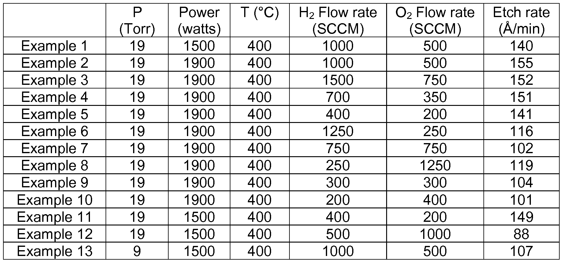
- Table 1 illustrates the change in removal rate of a boron-carbon film from the surface of a 300 millimeter substrate using varied process parameters.
- etching rate With respect to increased oxygen or hydrogen flow rates, excess oxygen or hydrogen in the plasma generally has little effect on etching rate.
- the rate of etching is limited by the amount of boron or carbon present on the surface of the boron-carbon film with which the oxygen or hydrogen can form a volatile compound, and generally is not significantly increased with the inclusion of excess process gas.
- the etching rate can be increased through the inclusion of additional process gas when the process gas is the limiting reactant (e.g., excess reactant sites are present on the surface of the boron-carbon film).
- Flow diagram 200 illustrates one embodiment of stripping a boron-carbon film; however, other embodiments are also contemplated.
- the oxygen-containing compound and hydrogen-containing compound in operation 206 may be introduced to the stripping chamber using a carrier gas, such as argon, helium, or nitrogen, having a flow rate less than 15,000 SCCM per 300 millimeter substrate.
- a carrier gas such as argon, helium, or nitrogen
- the inclusion of carrier gas to the processing volume may decrease the rate at which the boron-carbon film is etched, but may also increase plasma uniformity and stability.
- Figures 3A and 3B illustrate the effect of chamber pressure and RF power on etch rate when using a plasma containing oxygen and hydrogen.
- a boron-carbon film at 400°C was removed from a substrate using a plasma formed from 2,000 SCCM of hydrogen gas and 1 ,000 SCCM of oxygen gas at 1 ,000 watts of RF power.
- the etching rate of the boron-carbon film is correspondingly increased.
- etch rate of the boron-carbon film may be controlled by adjusting the pressure within the chamber.
- a boron-carbon film at 400°C was removed using plasma formed from 2,000 SCCM of hydrogen gas and 1 ,000 SCCM of oxygen gas.
- the chamber pressure was maintained at 9 Torr.
- the etching rate of the boron-carbon film is correspondingly increased.
- FIG. 4 is a flow diagram illustrating a method of removing a boron- carbon film using plasma generated from hydrogen and nitrous oxide according to one embodiment of the invention.
- Flow diagram 400 includes operations 102, 104, and 406.
- Operations 102 and 104 are similar to operations 102 and 104 described with reference to flow diagram 100.
- the substrate and the boron-carbon film thereon are exposed to a plasma formed from hydrogen and nitrous oxide in operation 406.
- flow diagram 200 uses oxygen as an oxidizing agent to remove carbon from the boron-carbon film
- flow diagram 400 uses nitrous oxide as an oxidizing agent.
- the use of nitrous oxide as an oxidizing agent allows the pressure within the chamber to be increased, thus increasing etch rate, while reducing the probability of undesired reactions occurring within the processing environment as is likely when using oxygen as an oxidizing agent.
- hydrogen gas and nitrous oxide gas are provided to the stripping chamber at flow rate of about 5 SCCM to about 15,000 SCCM for a 300 millimeter substrate to remove a boron-carbon layer from the surface of the substrate.
- the hydrogen gas and the nitrous oxide gas may each be provided at a flow rate of about 200 SCCM to about 4,000 SCCM.
- the hydrogen gas and the nitrous oxide gas are ionized using an RF generator operating at 13.56 MHz and applying about 100 watts to about 3,000 watts of power, such as about 1 ,500 watts to about 2,000 watts of power.
- the substrate is maintained at a heater temperature less than 750°C, such as at about 400°C.
- the pressure within the stripping chamber is maintained at less than 760 Torr, such as about 40 Torr to about 60 Torr.
- the nitrous oxide plasma and the hydrogen plasma react with the boron-carbon film to form volatile compounds which are then exhausted from the chamber.
- Table 2 illustrates some exemplary process recipes for removing a boron- carbon film from the surface of a 300 millimeter substrate using a plasma formed from hydrogen and nitrous oxide.
- nitrous oxide As illustrated in Table 2, the use of nitrous oxide as an oxidizing agent generally yields a greater etching rate than when using oxygen as an oxidizing agent. This is due partly to the higher chamber pressures which can be utilized when using nitrous oxide.
- the oxidizing gas may be a mixture of nitrous oxide and oxygen, in which case, the pressure in the chamber may be permitted to exceed 20 Torr.
- flow diagram 400 is described with reference to co-flowing nitrous oxide and hydrogen gas, it is contemplated that the nitrous oxide and hydrogen gas be independently provided to the chamber in a cyclical manner.
- carbon dioxide may be used in addition to or as an alternative to nitrous oxide.
- FIG. 5 is a flow diagram 500 illustrating a method of removing a boron- carbon film using plasma generated from water vapor according to one embodiment of the invention.
- Flow diagram 500 includes operations 102, 104, and 506.
- Operations 102 and 104 are similar to operations 102 and 104 described with reference to flow diagram 100.
- the substrate and the boron-carbon film thereon are exposed to a plasma formed from water vapor in operation 506.
- water vapor is produced by a water vapor generator (VWG) and is provided to a stripping chamber where the water vapor is ignited into a plasma to etch a boron-carbon film from the surface of a substrate.
- VWG water vapor generator
- the water vapor is introduced to the stripping chamber at a flow rate of about 5 SCCM to about 15,000 SCCM per 300 millimeter substrate.
- the substrate is maintained at a temperature less than about 750°C, such as about 300°C to about 500°C, while the pressure in the chamber is maintained at less than about 760 Torr, such as about 10 Torr to about 50 Torr, or about 10 Torr to about 760 Torr.
- RF power within a range of about 10 watts to 3,000 watts is applied to the water vapor to generate a plasma containing oxygen, hydrogen, and hydroxyl ions or radicals, which react with the boron-carbon film to form volatile compounds which are exhausted from the chamber.
- Flow diagram 500 illustrates one embodiment for stripping a boron-carbon film; however, additional embodiments are also contemplated.
- the water vapor may be generated via in situ steam generation.
- non-stoichiometric combinations of oxygen and hydrogen e.g., H x O y , where x and y may be integers or non-integers both greater than zero
- H x O y may be integers or non-integers both greater than zero
- some hydrogen peroxide may be generated by the water vapor generator.
- oxygen gas, helium gas, nitrogen gas, argon gas, nitrous oxide gas, and or/hydrogen gas may be provided to the stripping chamber in addition to water vapor.
- the addition of hydrogen has been found to increase the removal rate of the boron- carbon film, especially in boron-carbon films containing a higher concentration of boron as compared to carbon.
- the addition of other carrier gases, such as helium has been observed to lower the rate of removal of the boron-carbon film, while simultaneously improving etch uniformity.
- the water vapor may be used to strip a carbon film, such as amorphous carbon, containing substantially no boron.
- the water vapor may be used to strip a boron film, such as amorphous boron, containing substantially no carbon.
- a fluorine-containing gas or a chlorine-containing gas may be ionized in operation 506 in combination with the water vapor to increase the etching rate of the boron-carbon film.
- operation 104 may be omitted.
- the fluorine-containing gas or the chlorine-containing gas is generally provided to the chamber at a flow rate between about 10 SCCM and 50 SCCM.
- the flow rate of the fluorine-containing gas or the chlorine-containing gas is tapered, reduced, or eliminated when approaching the end of operation 506. It is believed that reduction in flow rate near the end of operation 106 does not undesirably etch exposed dielectric materials due to the mechanism in which the fluorine-containing gas or the chlorine-containing gas assists in removal of the boron-carbon layer.
- dielectric material on the substrate is exposed in vias or trenches formed into the substrate during a previous etching process, while boron- carbon material is exposed on the upper surface of the substrate.
- the fluorine- containing gas or the chlorine-containing gas which enters the chamber and is ignited into a plasma generally contacts and reacts with the boron-carbon layer prior to contacting the dielectric material in the vias or trenches.
- the probability of the fluorine-containing gas or the chlorine- containing gas contacting and undesirably removing the dielectric material is increased. Therefore, the flow rate of the fluorine-containing gas or the chlorine- containing gas is reduced as the thickness of the boron-containing layer decreases in order to reduce the probability of etching the dielectric material.
- the spacing between the substrate and a face place located within the chamber may be within a range of about 20 mils to about 600 mils. Reduced spacing between the substrate is beneficial when processing substrates in larger volumes (for example, when processing large area substrates) under higher pressures (for example, greater than about 7 Torr). When processing substrates at pressures greater than about 7 Torr, the reduced spacing facilitates plasma sustainability.
- the spacing between the substrate and the face plate may be about 300 mils.
- the spacing between the substrate and the face plate may be within a range of about 240 mils to about 270 mils.
- the spacing between the substrate and the face plate may be less than 200 mils.
- Table 3 illustrates a change in etch rate of a boron-carbon film in response to a change in process gas flow rate.
- Each of Examples 23-30 in Table 3 includes at least 500 SCCM of helium gas as a carrier gas to increase etch uniformity, and may contain additional carrier gas, as noted in Table 3.
- Table 3
- Example 29 which contains the highest total flow rate of carrier gas (250 SCCM of helium and 750 SCCM of argon) has the lowest etch rate.
- FIG. 6 illustrates the etching selectivity of water vapor plasma.
- Plasma A includes 1 ,000 SCCM of water vapor and 500 SCCM of helium generated into a plasma using 1900 watts of RF power.
- the stripping chamber is maintained at 50 Torr, and the substrate is maintained at 400°C.
- Plasma A etched the boron-carbon film at a rate of about 570 angstroms per minute, and did not etch silicon oxide, silicon nitride, or amorphous silicon.
- Plasma B includes 1 ,000 SCCM of water vapor, 250 SCCM of helium, and 150 SCCM of hydrogen generated into a plasma using 1900 watts of RF power.
- the stripping chamber is maintained at 50 Torr, and the substrate is maintained at 400°C.
- Plasma B etched the boron-carbon film at a rate of about 770 angstroms per minute, and did not etch silicon oxide, silicon nitride, or amorphous silicon.
- Benefits of the methods described herein include stripping boron-carbon films without damaging dielectric materials or underlying metal layers located on a substrate.
- the stripping methods allow for etching rate, as well as etching uniformity to be controlled by varying plasma composition.
Landscapes
- Drying Of Semiconductors (AREA)
Abstract
Description


Claims
Priority Applications (3)
| Application Number | Priority Date | Filing Date | Title |
|---|---|---|---|
| KR1020137031377A KR101682081B1 (en) | 2011-05-12 | 2012-04-27 | Methods of dry stripping boron-carbon films |
| CN201280015166XA CN103443909A (en) | 2011-05-12 | 2012-04-27 | Methods of dry stripping boron-arbon films |
| JP2014510355A JP5933694B2 (en) | 2011-05-12 | 2012-04-27 | Method for dry stripping boron carbon films |
Applications Claiming Priority (4)
| Application Number | Priority Date | Filing Date | Title |
|---|---|---|---|
| US201161485534P | 2011-05-12 | 2011-05-12 | |
| US61/485,534 | 2011-05-12 | ||
| US13/456,404 | 2012-04-26 | ||
| US13/456,404 US9299581B2 (en) | 2011-05-12 | 2012-04-26 | Methods of dry stripping boron-carbon films |
Publications (2)
| Publication Number | Publication Date |
|---|---|
| WO2012154429A2 true WO2012154429A2 (en) | 2012-11-15 |
| WO2012154429A3 WO2012154429A3 (en) | 2013-04-25 |
Family
ID=47139880
Family Applications (1)
| Application Number | Title | Priority Date | Filing Date |
|---|---|---|---|
| PCT/US2012/035659 Ceased WO2012154429A2 (en) | 2011-05-12 | 2012-04-27 | Methods of dry stripping boron-carbon films |
Country Status (6)
| Country | Link |
|---|---|
| US (1) | US9299581B2 (en) |
| JP (1) | JP5933694B2 (en) |
| KR (1) | KR101682081B1 (en) |
| CN (1) | CN103443909A (en) |
| TW (1) | TWI541062B (en) |
| WO (1) | WO2012154429A2 (en) |
Cited By (1)
| Publication number | Priority date | Publication date | Assignee | Title |
|---|---|---|---|---|
| CN114645281A (en) * | 2022-04-06 | 2022-06-21 | 岭南师范学院 | Method for removing carbon film on surface of metal workpiece |
Families Citing this family (47)
| Publication number | Priority date | Publication date | Assignee | Title |
|---|---|---|---|---|
| US9299581B2 (en) | 2011-05-12 | 2016-03-29 | Applied Materials, Inc. | Methods of dry stripping boron-carbon films |
| US9653327B2 (en) | 2011-05-12 | 2017-05-16 | Applied Materials, Inc. | Methods of removing a material layer from a substrate using water vapor treatment |
| US20140216498A1 (en) | 2013-02-06 | 2014-08-07 | Kwangduk Douglas Lee | Methods of dry stripping boron-carbon films |
| US9190290B2 (en) * | 2014-03-31 | 2015-11-17 | Applied Materials, Inc. | Halogen-free gas-phase silicon etch |
| US9691590B2 (en) * | 2015-06-29 | 2017-06-27 | Lam Research Corporation | Selective removal of boron doped carbon hard mask layers |
| US10418243B2 (en) * | 2015-10-09 | 2019-09-17 | Applied Materials, Inc. | Ultra-high modulus and etch selectivity boron-carbon hardmask films |
| US10490399B2 (en) * | 2016-03-09 | 2019-11-26 | Tokyo Electron Limited | Systems and methodologies for vapor phase hydroxyl radical processing of substrates |
| JP6971267B2 (en) | 2016-06-20 | 2021-11-24 | アプライド マテリアルズ インコーポレイテッドApplied Materials, Incorporated | Cleaning process to remove boron-carbon residues in the processing chamber at high temperatures |
| US10224224B2 (en) | 2017-03-10 | 2019-03-05 | Micromaterials, LLC | High pressure wafer processing systems and related methods |
| US10847360B2 (en) | 2017-05-25 | 2020-11-24 | Applied Materials, Inc. | High pressure treatment of silicon nitride film |
| US10622214B2 (en) | 2017-05-25 | 2020-04-14 | Applied Materials, Inc. | Tungsten defluorination by high pressure treatment |
| KR102574914B1 (en) * | 2017-06-02 | 2023-09-04 | 어플라이드 머티어리얼스, 인코포레이티드 | Dry Stripping of Boron Carbide Hardmasks |
| US10234630B2 (en) | 2017-07-12 | 2019-03-19 | Applied Materials, Inc. | Method for creating a high refractive index wave guide |
| US10269571B2 (en) | 2017-07-12 | 2019-04-23 | Applied Materials, Inc. | Methods for fabricating nanowire for semiconductor applications |
| US10179941B1 (en) | 2017-07-14 | 2019-01-15 | Applied Materials, Inc. | Gas delivery system for high pressure processing chamber |
| US10276411B2 (en) | 2017-08-18 | 2019-04-30 | Applied Materials, Inc. | High pressure and high temperature anneal chamber |
| JP6947914B2 (en) | 2017-08-18 | 2021-10-13 | アプライド マテリアルズ インコーポレイテッドApplied Materials,Incorporated | Annealing chamber under high pressure and high temperature |
| CN111095524B (en) | 2017-09-12 | 2023-10-03 | 应用材料公司 | Apparatus and method for fabricating semiconductor structures using protective barrier layers |
| US10636675B2 (en) | 2017-09-27 | 2020-04-28 | Applied Materials, Inc. | Methods of etching metal-containing layers |
| WO2019067538A1 (en) * | 2017-09-29 | 2019-04-04 | Tokyo Electron Limited | Methods and systems for coating a substrate with a fluid |
| US10643867B2 (en) | 2017-11-03 | 2020-05-05 | Applied Materials, Inc. | Annealing system and method |
| KR102585074B1 (en) | 2017-11-11 | 2023-10-04 | 마이크로머티어리얼즈 엘엘씨 | Gas delivery system for high pressure processing chamber |
| SG11202003438QA (en) | 2017-11-16 | 2020-05-28 | Applied Materials Inc | High pressure steam anneal processing apparatus |
| JP2021503714A (en) | 2017-11-17 | 2021-02-12 | アプライド マテリアルズ インコーポレイテッドApplied Materials,Incorporated | Capacitor system for high pressure processing system |
| US10354875B1 (en) * | 2018-01-08 | 2019-07-16 | Varian Semiconductor Equipment Associates, Inc. | Techniques for improved removal of sacrificial mask |
| JP7299898B2 (en) | 2018-01-24 | 2023-06-28 | アプライド マテリアルズ インコーポレイテッド | Seam repair using high pressure annealing |
| CN111902929B (en) | 2018-03-09 | 2025-09-19 | 应用材料公司 | High pressure annealing process for metal-containing materials |
| US10714331B2 (en) | 2018-04-04 | 2020-07-14 | Applied Materials, Inc. | Method to fabricate thermally stable low K-FinFET spacer |
| US10950429B2 (en) | 2018-05-08 | 2021-03-16 | Applied Materials, Inc. | Methods of forming amorphous carbon hard mask layers and hard mask layers formed therefrom |
| US10566188B2 (en) | 2018-05-17 | 2020-02-18 | Applied Materials, Inc. | Method to improve film stability |
| US10704141B2 (en) | 2018-06-01 | 2020-07-07 | Applied Materials, Inc. | In-situ CVD and ALD coating of chamber to control metal contamination |
| US10748783B2 (en) | 2018-07-25 | 2020-08-18 | Applied Materials, Inc. | Gas delivery module |
| KR102630751B1 (en) * | 2018-07-27 | 2024-01-29 | 어플라이드 머티어리얼스, 인코포레이티드 | 3D NAND etching |
| WO2020031224A1 (en) * | 2018-08-06 | 2020-02-13 | 株式会社日立ハイテクノロジーズ | Plasma treatment method and plasma ashing device |
| US10675581B2 (en) | 2018-08-06 | 2020-06-09 | Applied Materials, Inc. | Gas abatement apparatus |
| JP2022512802A (en) * | 2018-10-26 | 2022-02-07 | マトソン テクノロジー インコーポレイテッド | Water vapor-based fluorine-containing plasma for removing hard masks |
| JP7179172B6 (en) | 2018-10-30 | 2022-12-16 | アプライド マテリアルズ インコーポレイテッド | Method for etching structures for semiconductor applications |
| US11049728B2 (en) * | 2018-10-31 | 2021-06-29 | Entegris, Inc. | Boron-doped amorphous carbon hard mask and related methods |
| KR20210077779A (en) | 2018-11-16 | 2021-06-25 | 어플라이드 머티어리얼스, 인코포레이티드 | Film Deposition Using Enhanced Diffusion Process |
| CN109546012B (en) * | 2018-11-23 | 2021-10-26 | 京东方科技集团股份有限公司 | Organic film etching method and display substrate display area circuit repairing method |
| WO2020117462A1 (en) | 2018-12-07 | 2020-06-11 | Applied Materials, Inc. | Semiconductor processing system |
| US11702751B2 (en) * | 2019-08-15 | 2023-07-18 | Applied Materials, Inc. | Non-conformal high selectivity film for etch critical dimension control |
| US11901222B2 (en) | 2020-02-17 | 2024-02-13 | Applied Materials, Inc. | Multi-step process for flowable gap-fill film |
| KR102851412B1 (en) * | 2020-03-26 | 2025-08-26 | 어플라이드 머티어리얼스, 인코포레이티드 | Catalytic formation of boron and carbon films |
| JP7519532B2 (en) | 2020-07-30 | 2024-07-19 | インテグリス・インコーポレーテッド | Method for removing hard mask - Patent application |
| US11955318B2 (en) | 2021-03-12 | 2024-04-09 | Applied Materials, Inc. | Ash rate recovery method in plasma strip chamber |
| WO2024074929A1 (en) * | 2022-10-03 | 2024-04-11 | Rasirc, Inc. | Hydrogen peroxide plasma etch of ashable hard mask |
Family Cites Families (23)
| Publication number | Priority date | Publication date | Assignee | Title |
|---|---|---|---|---|
| US4975144A (en) | 1988-03-22 | 1990-12-04 | Semiconductor Energy Laboratory Co., Ltd. | Method of plasma etching amorphous carbon films |
| JPH05217965A (en) * | 1992-01-22 | 1993-08-27 | Nec Corp | Manufacture of semiconductor device |
| US6165891A (en) | 1999-11-22 | 2000-12-26 | Chartered Semiconductor Manufacturing Ltd. | Damascene structure with reduced capacitance using a carbon nitride, boron nitride, or boron carbon nitride passivation layer, etch stop layer, and/or cap layer |
| KR100316721B1 (en) | 2000-01-29 | 2001-12-12 | 윤종용 | Method of manufacturing semiconductor device having a silicide layer |
| US20020086547A1 (en) | 2000-02-17 | 2002-07-04 | Applied Materials, Inc. | Etch pattern definition using a CVD organic layer as an anti-reflection coating and hardmask |
| US6352921B1 (en) | 2000-07-19 | 2002-03-05 | Chartered Semiconductor Manufacturing Ltd. | Use of boron carbide as an etch-stop and barrier layer for copper dual damascene metallization |
| US6413852B1 (en) | 2000-08-31 | 2002-07-02 | International Business Machines Corporation | Method of forming multilevel interconnect structure containing air gaps including utilizing both sacrificial and placeholder material |
| TW476135B (en) | 2001-01-09 | 2002-02-11 | United Microelectronics Corp | Manufacture of semiconductor with air gap |
| JP3893939B2 (en) * | 2001-10-26 | 2007-03-14 | セイコーエプソン株式会社 | Resist stripping apparatus, resist stripping method, and semiconductor device manufacturing method |
| US6541397B1 (en) | 2002-03-29 | 2003-04-01 | Applied Materials, Inc. | Removable amorphous carbon CMP stop |
| US6884733B1 (en) | 2002-08-08 | 2005-04-26 | Advanced Micro Devices, Inc. | Use of amorphous carbon hard mask for gate patterning to eliminate requirement of poly re-oxidation |
| US6939794B2 (en) | 2003-06-17 | 2005-09-06 | Micron Technology, Inc. | Boron-doped amorphous carbon film for use as a hard etch mask during the formation of a semiconductor device |
| US7105431B2 (en) * | 2003-08-22 | 2006-09-12 | Micron Technology, Inc. | Masking methods |
| US7638440B2 (en) | 2004-03-12 | 2009-12-29 | Applied Materials, Inc. | Method of depositing an amorphous carbon film for etch hardmask application |
| JP4879159B2 (en) | 2004-03-05 | 2012-02-22 | アプライド マテリアルズ インコーポレイテッド | CVD process for amorphous carbon film deposition |
| US20060199393A1 (en) | 2004-06-29 | 2006-09-07 | Taiwan Semiconductor Manufacturing Co., Ltd. | H20 plasma and h20 vapor methods for releasing charges |
| KR100533978B1 (en) | 2004-06-30 | 2005-12-07 | 주식회사 하이닉스반도체 | Method for fabrication of semiconductor device |
| KR100637689B1 (en) | 2005-04-21 | 2006-10-24 | 주식회사 하이닉스반도체 | Contact Formation Method of Semiconductor Device Using Solid Phase Epitaxy Method |
| KR20070081649A (en) | 2006-02-13 | 2007-08-17 | 삼성전자주식회사 | Manufacturing Method of Semiconductor Device |
| US20080115808A1 (en) | 2006-11-20 | 2008-05-22 | Applied Materials, Inc. | In-situ chamber cleaning for an rtp chamber |
| US8337950B2 (en) | 2007-06-19 | 2012-12-25 | Applied Materials, Inc. | Method for depositing boron-rich films for lithographic mask applications |
| US9299581B2 (en) | 2011-05-12 | 2016-03-29 | Applied Materials, Inc. | Methods of dry stripping boron-carbon films |
| US9653327B2 (en) | 2011-05-12 | 2017-05-16 | Applied Materials, Inc. | Methods of removing a material layer from a substrate using water vapor treatment |
-
2012
- 2012-04-26 US US13/456,404 patent/US9299581B2/en active Active
- 2012-04-27 JP JP2014510355A patent/JP5933694B2/en active Active
- 2012-04-27 CN CN201280015166XA patent/CN103443909A/en active Pending
- 2012-04-27 WO PCT/US2012/035659 patent/WO2012154429A2/en not_active Ceased
- 2012-04-27 KR KR1020137031377A patent/KR101682081B1/en active Active
- 2012-05-02 TW TW101115611A patent/TWI541062B/en active
Cited By (2)
| Publication number | Priority date | Publication date | Assignee | Title |
|---|---|---|---|---|
| CN114645281A (en) * | 2022-04-06 | 2022-06-21 | 岭南师范学院 | Method for removing carbon film on surface of metal workpiece |
| CN114645281B (en) * | 2022-04-06 | 2023-11-24 | 岭南师范学院 | Method for removing carbon film on surface of metal workpiece |
Also Published As
| Publication number | Publication date |
|---|---|
| KR101682081B1 (en) | 2016-12-02 |
| TW201247312A (en) | 2012-12-01 |
| US20120285492A1 (en) | 2012-11-15 |
| JP2014516205A (en) | 2014-07-07 |
| WO2012154429A3 (en) | 2013-04-25 |
| CN103443909A (en) | 2013-12-11 |
| US9299581B2 (en) | 2016-03-29 |
| KR20140036203A (en) | 2014-03-25 |
| TWI541062B (en) | 2016-07-11 |
| JP5933694B2 (en) | 2016-06-15 |
Similar Documents
| Publication | Publication Date | Title |
|---|---|---|
| US9299581B2 (en) | Methods of dry stripping boron-carbon films | |
| US10510518B2 (en) | Methods of dry stripping boron-carbon films | |
| JP6811284B2 (en) | Manufacturing method of 3D NAND flash memory | |
| TWI453818B (en) | Plasma etching method | |
| JP6871233B2 (en) | Methods for Etching Silicon-Containing Films | |
| US7368394B2 (en) | Etch methods to form anisotropic features for high aspect ratio applications | |
| KR101476435B1 (en) | Multi-layer resist plasma etch method | |
| KR101391347B1 (en) | Etching gas | |
| US9287124B2 (en) | Method of etching a boron doped carbon hardmask | |
| EP3038142A1 (en) | Selective nitride etch | |
| JP6788177B2 (en) | Dry etching method, dry etching agent and semiconductor device manufacturing method | |
| CN107017162B (en) | Ultra-high selectivity polysilicon etching with high throughput | |
| TWI284370B (en) | Use of hypofluorites, fluoroperoxides, and/or fluorotrioxides as oxidizing agent in fluorocarbon etch plasmas | |
| KR102765856B1 (en) | Dry etching method and method for manufacturing semiconductor devices | |
| JP6544215B2 (en) | Dry etching method | |
| WO2020150100A1 (en) | Selective plasma etching of silicon oxide relative to silicon nitride by gas pulsing | |
| JP7852678B2 (en) | Etching method using halogen fluoride, semiconductor manufacturing method | |
| KR20220063927A (en) | Substrate processing method | |
| Hsiao | Cryogenic plasma etching for SiO2/SiN dielectric films: a mini review | |
| TW202527027A (en) | Dielectric etching using chf |
Legal Events
| Date | Code | Title | Description |
|---|---|---|---|
| 121 | Ep: the epo has been informed by wipo that ep was designated in this application |
Ref document number: 12782941 Country of ref document: EP Kind code of ref document: A2 |
|
| ENP | Entry into the national phase |
Ref document number: 2014510355 Country of ref document: JP Kind code of ref document: A |
|
| NENP | Non-entry into the national phase |
Ref country code: DE |
|
| ENP | Entry into the national phase |
Ref document number: 20137031377 Country of ref document: KR Kind code of ref document: A |
|
| 122 | Ep: pct application non-entry in european phase |
Ref document number: 12782941 Country of ref document: EP Kind code of ref document: A2 |