WO2012153713A1 - 情報処理装置、情報処理装置の制御方法、制御プログラムおよび記録媒体 - Google Patents
情報処理装置、情報処理装置の制御方法、制御プログラムおよび記録媒体 Download PDFInfo
- Publication number
- WO2012153713A1 WO2012153713A1 PCT/JP2012/061691 JP2012061691W WO2012153713A1 WO 2012153713 A1 WO2012153713 A1 WO 2012153713A1 JP 2012061691 W JP2012061691 W JP 2012061691W WO 2012153713 A1 WO2012153713 A1 WO 2012153713A1
- Authority
- WO
- WIPO (PCT)
- Prior art keywords
- display
- information processing
- unit
- mobile phone
- content
- Prior art date
- Legal status (The legal status is an assumption and is not a legal conclusion. Google has not performed a legal analysis and makes no representation as to the accuracy of the status listed.)
- Ceased
Links
Images












Classifications
-
- H—ELECTRICITY
- H04—ELECTRIC COMMUNICATION TECHNIQUE
- H04M—TELEPHONIC COMMUNICATION
- H04M1/00—Substation equipment, e.g. for use by subscribers
- H04M1/72—Mobile telephones; Cordless telephones, i.e. devices for establishing wireless links to base stations without route selection
- H04M1/724—User interfaces specially adapted for cordless or mobile telephones
- H04M1/72403—User interfaces specially adapted for cordless or mobile telephones with means for local support of applications that increase the functionality
Definitions
- the present invention relates to an information processing apparatus that processes information stored in its own apparatus and information stored in another apparatus, a control method for the information processing apparatus, a control program, and a recording medium.
- mobile information terminals such as mobile phones are equipped with high-performance arithmetic processing devices, large-capacity storage devices, cameras capable of taking pictures and videos, etc., and contents handled by the mobile information terminals (contact information) , Text, images, videos, music information, etc.) and the amount of data is increasing. For this reason, the user holds a large amount of various contents in the portable information terminal, and the contents held by the users are exchanged with each other.
- Patent Document 1 discloses a terminal device including an ID tag reader that detects an ID tag held by a user and transmits data operated during the ID tag detection period to the detected user terminal device. Are listed.
- Patent Document 2 describes a mobile phone that includes a display unit including a light receiving element and that transmits and receives data by optical communication with the display units of a plurality of mobile phones facing each other.
- Japanese Patent Application Laid-Open No. 2004-151867 is a mobile phone having a sensor on a side surface, and performs various processing on each mobile phone for content stored in each mobile phone in a state where the side surfaces of a plurality of mobile phones are in contact with each other. Is described.
- Patent Documents 4 and 5 are exemplified as documents indicating the technical level.
- Patent Document 4 in a communication system including a plurality of communication terminals that transmit and receive images and messages to and from other communication terminals and display images, a user's captured image is displayed on the communication terminals when the distance between the communication terminals is short
- a technique for displaying a user's avatar image on a communication terminal when the distance between the communication terminals is long is described.
- Patent Document 5 in a display system including a plurality of devices including a position detection unit that detects the position of another device and a display unit, display data having a size larger than one display unit is based on the positional relationship of each device. Thus, a technique for displaying continuously on the display unit of each device is described.
- Patent Document 3 when sharing data, mobile phones are arranged side by side.
- the present inventor has another state that more intuitively represents a state in which data between two terminals is shared. Think.
- the present invention has been made in view of the above problems, and an object of the present invention is to provide an information processing apparatus and an information processing apparatus that allow a user to more intuitively and easily operate data sharing between apparatuses.
- an information processing apparatus is an information processing apparatus including a display unit, and the other information processing is performed on the back side opposite to the display surface side on which the display unit is disposed.
- the back side device detecting unit detects that there is a device and the back side device detecting unit detects another information processing device, the content stored in the other information processing device is indicated from the other information processing device.
- Content identification information acquisition means for acquiring content identification information, a first display area corresponding to the own device, and a second display area corresponding to the other information processing apparatus are set in the display area of the display unit,
- the display information for operation specifying the content stored in the device itself is displayed in the first display area, and the other information based on the content identification information acquired by the content identification information acquisition means.
- the operation display information management device to specify the content to be stored is characterized by comprising a display control means for displaying on the second display area.
- An information processing apparatus control method is a method for controlling an information processing apparatus provided with a display unit in order to solve the above-described problem, and is a back surface opposite to a display surface side on which the display unit is disposed.
- a back side device detecting step for detecting that there is another information processing device on the side, and after the other information processing device is detected in the back side device detecting step, the other information
- a content identification information acquisition step for acquiring content identification information indicating content stored in the processing device; a display region of the display unit; a first display region corresponding to the own device; and a first display region corresponding to the other information processing device.
- the said back side apparatus detection means detects that there exists another information processing apparatus in the back side opposite to the display surface side where the said display part is arrange
- the back side device detecting means detects another information processing apparatus
- the means acquires content identification information indicating the content stored in the other information processing apparatus from the other information processing apparatus
- the display control means Sets the first display area corresponding to its own apparatus and the second display area corresponding to the other information processing apparatus in the display area of the display unit, and specifies the content stored in the own apparatus An operation for displaying the display information in the first display area and specifying the content stored in the other information processing device based on the content identification information acquired by the content identification information acquisition means.
- the user places the other information processing device on the back side of the information processing device, so that the content stored in the information processing device and the other information processing device are displayed on the display unit of the information processing device.
- the content to be stored can be displayed separately. That is, the user superimposes the information processing device on the other information processing device, so that not only the content stored in the information processing device but also the other information processing device under the information processing device is stored.
- the content to be stored can be recognized.
- the upper information processing By classifying and displaying both contents stored in the two information processing apparatuses on the display unit of the apparatus, the user can recognize the contents stored in the two information processing apparatuses without any inconvenience.
- an information processing apparatus is an information processing apparatus including a display unit, and detects that there is another information processing device on the display surface side where the display unit is disposed.
- Content identification information transmission for transmitting content identification information indicating the content stored in the own apparatus to the other information processing apparatus when the surface side apparatus detection means detects the other information processing apparatus. Means.
- An information processing apparatus control method is a method for controlling an information processing apparatus including a display unit in order to solve the above-described problem, and is configured to perform other information processing on the display surface side where the display unit is disposed.
- a front-side device detecting step for detecting the presence of the device, and content identification indicating the content stored in the own device after the other information-processing device is detected in the front-side device detecting step
- a content identification information transmitting step for transmitting information.
- the said surface side apparatus detection means detects that there exists another information processing apparatus in the display surface side in which the said display part is arrange
- the device detection unit detects another information processing device, it transmits content identification information indicating the content stored in the device itself to the other information processing device.
- the user can notify the other information processing apparatus of the content stored in the information processing apparatus by placing the other information processing apparatus on the display surface side of the information processing apparatus. That is, the user can notify the other information processing apparatus of the content stored in the information processing apparatus by superimposing the other information processing apparatus on the information processing apparatus.
- the user can inform other users of the content held by the user with an intuitive and simple operation in which the other information processing device possessed by another user is superimposed on the information processing device possessed by the user. There is an effect.
- the information processing apparatus may be realized by a computer.
- a control program for causing the computer to realize the information processing apparatus by causing the computer to operate as each unit of the information processing apparatus, and A computer-readable recording medium on which it is recorded also falls within the scope of the present invention.
- the information processing apparatus includes a back side device detection unit that detects that there is another information processing apparatus on the back side opposite to the display side on which the display unit is disposed, Content identification information acquisition means for acquiring content identification information indicating content stored in the other information processing apparatus from the other information processing apparatus when the back side apparatus detection means detects the other information processing apparatus;
- a first display area corresponding to the own apparatus and a second display area corresponding to the other information processing apparatus are set, and operation display information for specifying content stored in the own apparatus is displayed.
- An operation display for identifying content stored in the other information processing apparatus based on the content identification information acquired by the content identification information acquisition means while being displayed in the first display area Distribution of a configuration and a display control means for displaying on the second display area.
- the control method of the information processing device includes a back side device detection step for detecting that there is another information processing device on the back side opposite to the display surface side on which the display unit is disposed, A content identification information acquisition step of acquiring content identification information indicating the content stored in the other information processing device from the other information processing device after the other information processing device is detected in the back side device detection step;
- the operation display for setting the first display area corresponding to the own apparatus and the second display area corresponding to the other information processing apparatus in the display area of the display unit and specifying the content stored in the own apparatus The content is displayed in the first display area, and the content stored in the other information processing apparatus based on the content identification information acquired by the content identification information acquisition means.
- the operation display information for identifying a and a display control step of displaying on the second display area.
- the information processing apparatus includes a surface-side device detection unit that detects that there is another information processing apparatus on the display surface side where the display unit is disposed, and the surface-side device detection unit includes other When the information processing apparatus is detected, the apparatus includes a content identification information transmitting unit that transmits content identification information indicating the content stored in the self apparatus to the other information processing apparatus.
- the information processing apparatus control method includes a surface-side apparatus detection step for detecting that there is another information processing apparatus on the display surface side where the display unit is disposed, and the surface-side apparatus detection step. And a content identification information transmitting step of transmitting content identification information indicating content stored in the device to the other information processing device after the other information processing device is detected.
- the user can inform other users of the content held by the user with an intuitive and simple operation in which the other information processing device possessed by another user is superimposed on the information processing device possessed by the user. There is an effect.
- FIG. 5 is a block diagram illustrating an example of a configuration of a main part of a mobile phone according to a second embodiment of the present invention. It is a figure which shows the external appearance of the front side and back side of the said mobile phone. It is a figure which shows the external appearance of the side view in the state in which the said two mobile phones overlap.
- FIG. 10 showing a third embodiment of the present invention, is a block diagram illustrating an example of a main part configuration of a mobile phone. It is a figure which shows the external appearance of the front side and back side of the said mobile phone. It is a figure which shows a mode that it shifts to the state where the said two mobile telephones overlap, (a) is a figure which shows the external view of the side view in the state before the two said mobile telephones overlap, (b) It is a figure which shows the external appearance of the side view in the state in which two mobile telephones overlap.
- FIG. 10 is a block diagram illustrating an example of a main part configuration of a mobile phone according to a fourth embodiment of the present invention. It is a figure which shows the external appearance of the front side and back side of the said mobile phone. It is a figure which shows the external appearance of the side view in the state in which the said two mobile phones overlap. It is a flowchart which shows an example of the multilayer state determination process contained in the communication application execution process mounted in the said mobile telephone, and the communication connection establishment process of an upper terminal and a lower terminal.
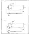
- FIG. 24 is a cross-sectional side view of the schematic structure of the casings of the two mobile phones in the multi-layer state, where (a) shows the case where the mobile phone shown in FIG. 23 is in the multi-layer state, and (b) is FIG. The case where the mobile phone shown in FIG. It is sectional drawing of the side view which shows another example of schematic structure of the housing
- ⁇ Outline of the present invention In the present invention, two information processing devices such as a mobile phone are stacked so that data stored in each information processing device can be transmitted to and received from each other, and each information processing device stores the information in the display unit of the upper information processing device.
- the data to be displayed is displayed in a different area for each information processing apparatus. Further, according to the present invention, in this state, data transmission / reception between the upper and lower information processing apparatuses can be executed by an operation on the upper information processing apparatus.
- a mobile phone will be exemplified as the information processing apparatus, and the present invention will be described in detail based on each embodiment.
- the present invention basically, when the mobile phone is starting a predetermined application, it is detected that two mobile phones are overlapping, and the upper mobile phone displays the data stored in each mobile phone. Or data transmission / reception.
- this application is referred to as “communication application to be loaded”.
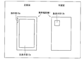
- the mobile phone 1 is equipped with a touch panel photosensor liquid crystal as a main display unit (display unit) 13a on the front side (display side) and a sub-display on the back side. It is assumed that an optical sensor liquid crystal is mounted as the part 13b.
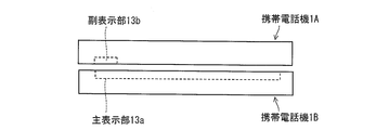
- the sub-display unit 13b detects light emitted from the main display unit 13a of another mobile phone, whereby the mobile phone 1 is another mobile phone on the back side. It is determined that and are overlapping. Therefore, as shown in FIG. 3, the sub-display unit 13b of the mobile phone 1A is positioned opposite to the main display unit 13a of the other mobile phone 1B when the mobile phone 1A and the other mobile phone 1B overlap each other.
- the arrangement and the size are not limited to those shown in FIG.
- the size of the main display unit 13a and the sub display unit 13b, the arrangement of the main display unit 13a on the front side of the mobile phone 1, and the arrangement of the sub display unit 13b on the back side of the mobile phone 1 can be appropriately designed. Good.
- the optical sensor 17a of the main display part 13a detects the shadow of the object on the front side of the mobile phone 1a, so that the mobile phone 1a overlaps with another mobile phone 1a on the front side. It is determined that. Therefore, the optical sensor 17a only needs to be able to detect whether there is an object on the front side of the mobile phone 1a, and the arrangement, size, and the like of the optical sensor 17a (main display unit 13a) may be appropriately designed.
- the mobile phone 1 on the upper side is referred to as a mobile phone 1A
- the mobile phone 1 on the lower side is referred to as a mobile phone 1B
- the upper side and the lower side are referred to. Unless otherwise distinguished, they are collectively referred to as the mobile phone 1.
- the information processing system includes the mobile phone 1A on the upper side and the mobile phone 1B on the lower side.
- FIG. 1 is a block diagram illustrating an example of a main configuration of the mobile phone 1.
- the mobile phone 1 includes a control unit 11, a storage unit 12, a main display unit 13a, a sub display unit 13b, a short-range wireless communication unit 14, a telephone network communication unit 15, and an operation unit (input means) 16a. It has.
- the mobile phone 1 may include members such as a voice input unit and a voice output unit, but these members are not shown because they are not related to the features of the invention.
- control unit 11A indicates the control unit 11 of the mobile phone 1A
- main display unit 13aB indicates the main display unit 13a of the mobile phone 1B.
- the main display unit 13a and the sub display unit 13b are composed of the optical sensor liquid crystal.
- the optical sensor liquid crystal is a sensor that incorporates an optical sensor on the transistor shape surface of the liquid crystal panel, and recognizes finger multi-touch (multi-point detection), pen movement, and shape on the liquid crystal surface. That is, the main display unit 13a and the sub display unit 13b include an optical sensor (input unit) 17a and an optical sensor 17b, respectively, and have a function of detecting light in addition to an image display function as a display unit.
- the optical sensor 17a and the optical sensor 17b function as an operation unit that receives a user's input operation and also functions as a detector that detects another mobile phone 1.
- the short-range wireless communication unit 14 communicates with other devices (for example, other mobile phones 1 and the like) by wireless communication means, and exchanges data according to instructions from the control unit 11.
- the short-range wireless communication unit 14 performs wireless communication using Bluetooth (registered trademark), but is not limited thereto.
- the short-range wireless communication unit 14 may perform communication using a wireless communication technique such as WiFi (Wireless Fidelity), WiMAX (Worldwide Interoperability for Microwave Access), IrDA, IrSimple, and the like.
- the telephone network communication unit 15 communicates with other devices via the mobile phone network, and exchanges voice data and communication data in accordance with instructions from the control unit 11.
- the operation unit 16a is configured by an input device such as an operation button, and the user inputs an instruction signal to the mobile phone 1 to operate the mobile phone 1.
- the control unit 11 performs various calculations by executing a program read from the storage unit 12 to a temporary storage unit (not shown), and comprehensively controls each unit included in the mobile phone 1. .
- the control unit 11 reads out communication application data to be placed from the storage unit 12.
- the control unit 11 first acquires data from the other mobile phone 1.
- the control part 11 displays the data which the own apparatus and the other mobile telephone 1 memorize
- the control unit 11 includes a multilayer state determination unit 31, a display control unit (display control unit) 32, an input operation specifying unit 33, a communication connection control unit 34, and a content processing unit 35 as functional blocks. is there.
- Each functional block (31 to 35) of the control unit 11 includes a program stored in a storage device realized by a CPU (central processing unit), a ROM (read only memory), and the like (random access memory). This can be realized by reading out and executing the temporary storage unit realized by the above.
- the multi-layer state determination unit 31 determines whether or not the mobile phone 1 is in a state where it overlaps with another mobile phone 1.
- a state in which the mobile phone 1 overlaps with another mobile phone 1 is referred to as a multi-layer state.
- a state in which the cellular phone 1A and the cellular phone 1B are overlapped is defined as a multilayered state.
- the multilayer state determination unit 31 includes an upper terminal state determination unit (back side device detection unit) 41 and a lower terminal state determination unit (front side device detection unit) 42.
- the upper terminal state determination unit 41 determines whether or not the own device is the upper terminal A (mobile phone 1A) above the other mobile phone 1. In other words, the upper terminal state determination unit 41 determines whether or not there is another mobile phone 1 on the back side of the own device. In the present embodiment, the upper terminal state determination unit 41 determines whether or not the optical sensor 17b of the sub display unit 13b has detected predetermined light emitted from the main display unit 13a. The upper terminal state determination unit 41 determines that the device is the upper terminal A when the optical sensor 17b determines that the predetermined light emitted from the main display unit 13a is detected. More specifically, the upper terminal state determination unit 41 determines whether the optical sensor 17b of the sub display unit 13b has detected light having a predetermined frequency at a predetermined light receiving interval.
- the upper terminal state determination unit 41 determines that the own device is the upper terminal A, the upper terminal state determination unit 41 notifies the communication connection control unit 34 to that effect.
- the lower terminal state determination unit 42 determines whether or not the own device is the lower terminal B (mobile phone 1B) on the lower side of the other mobile phone 1. In other words, the lower terminal state determination unit 42 determines whether there is another mobile phone 1 on the front side of the own device. In the present embodiment, the lower terminal state determination unit 42 determines whether or not the optical sensor 17a of the main display unit 13a has detected a shadow. When the optical sensor 17a detects a shadow, the lower terminal state determination unit 42 It is determined that
- the lower terminal state determination unit 42 determines that the own device is the lower terminal B
- the lower terminal state determination unit 42 notifies the display control unit 32 to that effect and emits light of a predetermined frequency from the main display unit 13a to the display control unit 32. Instructs to emit light at a predetermined light emission interval. Further, when the lower terminal state determination unit 42 determines that the own device is the lower terminal B, the lower terminal state determination unit 42 notifies the communication connection control unit 34 to that effect.
- the upper terminal state determination unit 41 determines whether or not the optical sensor 17b has detected a predetermined light emitted from the main display unit 13a in order to determine whether or not the terminal is the upper terminal A. Is. That is, the upper terminal state determination unit 41 determines whether the sub display unit 13b faces the main display unit 13a of the mobile phone 1B, and detects light emitted from the main display unit 13a (detected by the optical sensor 17b). (Light) may be arbitrary and may be set appropriately in advance.
- the input operation specifying unit 33 acquires user input operation signals from the operation unit 16a, the optical sensor 17a, and the optical sensor 17b, and specifies what input operation the acquired input operation signal is.
- the input operation specifying unit 33 specifies, for example, that the communication application loaded by the user's input operation is activated or ended, or specifies that the content is moving or copying.
- the input operation specifying unit 33 notifies the display control unit 32 or the content processing unit 35 of the content of the input operation according to the content of the specified input operation.
- the communication connection control unit 34 establishes a communication connection between the short-range wireless communication unit 14 and the short-range wireless communication unit of another mobile phone 1.
- the communication connection control unit 34 receives a notification that the own device is the upper terminal A from the upper terminal state determination unit 41, the communication connection control unit 34 transmits a communication start signal to the mobile phone 1B via the short-range wireless communication unit 14.
- the communication connection control unit 34 transmits the terminal ID of its own device to the mobile phone 1B via the short-range wireless communication unit 14.
- the communication connection control unit 34 when the communication connection control unit 34 receives a notification that the own device is the lower terminal B from the lower terminal state determination unit 42, the communication connection control unit 34 instructs the short-range wireless communication unit 14 to start waiting for communication connection. .
- the communication connection control unit 34 transmits the terminal ID of the own device to the mobile phone 1A via the short-range wireless communication unit 14.
- the terminal ID is information for identifying a device for specifying a partner at the time of communication connection, and is, for example, an address.
- the content processing unit 35 processes content held by its own device, and performs, for example, content movement and duplication, content reproduction, and content deletion. Further, the content processing unit 35 stores the acquired content in the storage unit 12. In addition, when the content processing unit 35 is in a layered state with another mobile phone 1, the content processing unit 35 processes content held by the other mobile phone.
- the content processing unit 35 includes a content acquisition unit (content identification information acquisition unit, mobile duplication unit) 43 and a content transmission unit (content identification information transmission unit, mobile replication unit) 44.
- the content acquisition unit 43 in a multi-layer state with another mobile phone 1, establishes a communication connection, and then, from another mobile phone 1, content entity data held by the other mobile phone 1 or content identification information indicating the content Is something to get.
- the content identification information is information that uniquely identifies the content held by the mobile phone 1, and is, for example, a content ID or a file name of the content.
- the content transmission unit 44 transmits the content entity data held by the own device or the content identification information indicating the content to the other mobile phone 1. To be sent.
- the content transmission unit 44 may read the content identification information and the content attachment information from the storage unit 12 and transmit the read content identification information and content attachment information to another mobile phone 1.
- the content accessory information is information including a thumbnail image of the content, content type information of the content, content size information, and content creation date / time information.
- the display control unit 32 displays images on the main display unit 13a and the sub display unit 13b based on instructions from the lower terminal state determination unit 42, the input operation specifying unit 33, and the like.
- the display control unit 32 includes a shared content display area WA (first display area) corresponding to its own device and a shared content display area WB (second display) corresponding to another mobile phone 1 in the display area of the main display unit 13a. Area).
- the display control unit 32 displays the operation display information for specifying the content held by the own device in the shared content display area WA, and displays the operation display information for specifying the content held by the other mobile phone 1 as the shared content display. Display in the area WB.
- the display information for operation only needs to be information that allows the user to specify the content, such as a file name, an icon, and a thumbnail of the content.
- the display control unit 32 may use the content identification information as the operation display information and display the content ID or the file name of the content on the display unit. Further, when the content acquisition unit acquires the content identification information and the content attached information, the display control unit 32 uses the content attached information as the operation display information, and displays the content with an icon or a thumbnail indicating the type of the content. May be.
- the storage unit 12 stores programs, data, and the like that the control unit 11 refers to. For example, images, videos, text data, html data, contact information, and the like that the content processing unit 35 transmits and receives with other mobile phones. Various contents such as application data are stored.
- the content that can be moved or copied with another mobile phone 1 when executing the communication application to be placed may be all of the content held by the mobile phone 1 or a part of the content.
- a content that can be moved or copied with another mobile phone 1 may be set in advance.
- content that is held by the mobile phone 1 and that can be moved or copied with another mobile phone 1 when a communication application to be loaded is executed is referred to as shared content.
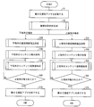
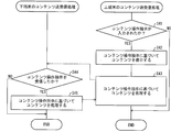
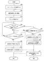
- FIG. 4 is a flowchart illustrating an example of a communication application execution process to be placed on the mobile phone 1.
- the control unit 11 activates a communication application to be loaded based on a user operation (S1).
- the multi-layer state determination unit 31 determines whether or not the mobile phone 1 is in a multi-layer state where it overlaps with another mobile phone 1, and determines whether the own device is the upper terminal A or the lower terminal B. Specify (S2).
- the mobile phone 1A which is the upper terminal A
- the mobile phone 1B which is the lower terminal B
- both perform content display processing and the cellular phone 1A displays the contents held by the cellular phones 1A and 1B on the main display portion 13aA (S4A, S4B).
- both perform content transmission / reception processing based on the user's operation received by the mobile phone 1A, and move, copy, etc. the content (S5A, S5B).
- both determine whether or not the two mobile phones 1 are separated S6A, S6B. If the multi-layered state is maintained (NO in S6A and S6B), both continue processing S5A and S5B, respectively, while the two mobile phones 1 are not multi-layered (YES in S6A and S6B). Both end communication applications to be loaded (S7A, S7B).
- FIG. 5 is a flowchart illustrating an example of the multistory state determination process.
- FIG. 6 is a flowchart illustrating an example of communication connection establishment processing between the upper terminal and the lower terminal.
- FIG. 7 is a flowchart illustrating an example of content display processing of the upper terminal and the lower terminal.
- FIG. 8 is a flowchart illustrating an example of content transmission / reception processing of the upper terminal and the lower terminal.
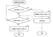
- the multilayer state determination process will be described in detail with reference to FIG. 5, after starting the communication application to be mounted, the lower terminal state determination unit 42 of the mobile phone 1 determines whether or not the light sensor 17a of the main display unit 13a has detected a shadow (S11).
- the lower terminal state determination unit 42 determines that the own device is the lower terminal B (S12), and notifies the display control unit 32 accordingly.
- the display control unit 32B causes the main display unit 13aB to emit light having a predetermined frequency at a predetermined light emission interval. That is, the display control unit 32B causes the main display unit 13aB to blink (S13).
- the upper terminal state determination unit 41 determines whether the optical sensor 17b of the sub display unit 13b has detected blinking display of the main display unit 13a. (S14). When the optical sensor 17b detects blinking display (YES in S14), the upper terminal state determination unit 41 determines that the own device is the upper terminal A (S15). When the optical sensor 17b does not detect the blinking display (NO in S14), the process returns to S11 again.
- the multi-layer state determination process is performed after the communication application to be loaded is activated, but the present invention is not limited to this.
- the control unit 11 may activate a communication application to be placed, and the lower terminal state determination unit 42 may determine that the own device is the lower terminal B.
- the control unit 11 may activate a communication application to be placed, and the upper terminal state determination unit 41 may determine that the own device is the upper terminal A.
- the control unit 11 displays an error on the main display unit 13a and Display a message that prompts you to enter the state, or end the communication app that you want to post if timed out.
- the communication connection control unit 34B Upon receiving the communication start signal from the mobile phone 1A, the communication connection control unit 34B transmits the terminal ID of the own device (mobile phone 1B) to the mobile phone 1A (S23). When receiving the terminal ID of the mobile phone 1B from the mobile phone 1B, the communication connection control unit 34A transmits the terminal ID of its own device (mobile phone 1A) to the mobile phone 1B (S24).
- the communication connection control unit 34B receives the terminal ID from the mobile phone 1A and completes the establishment of the communication connection.
- the communication connection control unit 34A receives the response to the terminal ID transmission and the establishment of the communication connection is completed. Make sure.
- the content transmitting unit 44B when the mobile phone 1B receives the shared content request instruction from the mobile phone 1A after establishing the communication connection, the content transmitting unit 44B, from the storage unit 12B, the shared content identification information indicating the shared content of its own device (mobile phone 1B) Is read. Then, the content transmission unit 44B transmits the read shared content identification information to the mobile phone 1A via the short-range wireless communication unit 14B (S32).
- the content acquisition unit 43A When the content acquisition unit 43A receives the shared content identification information from the mobile phone 1B, the content acquisition unit 43A reads the shared content identification information indicating the shared content of the own device (the mobile phone 1A) from the storage unit 12A. Then, content acquisition unit 43A outputs the shared content identification information of mobile phone 1A and the shared content identification information of mobile phone 1B to display control unit 32A.
- the display control unit 32A sets the shared content display areas WA and WB in the display area of the main display unit 13aA. Then, the display control unit 32A displays operation display information for specifying the shared content indicated by the shared content identification information of the mobile phone 1A in the shared content display area WA.
- the display control unit 32A displays operation display information for specifying the shared content indicated by the shared content identification information of the mobile phone 1B in the shared content display area WB (S33).
- the content transmission unit 44B reads the shared content identification information and the shared content attached information from the storage unit 12B, and transmits the read shared content identification information and shared content attached information to the mobile phone 1A. Also good.
- the attached information of the shared content is information including a thumbnail image of the shared content, content type information of the shared content, size information of the shared content, and creation date information of the shared content.
- the mobile phone 1B transmits the shared content identification information after receiving the shared content request instruction from the mobile phone 1A.
- the present invention is not limited to this.
- the mobile phone 1B transmits the shared content identification information to the mobile phone 1A after the communication connection is established, and the mobile phone 1A waits for the shared content identification information to be transmitted from the mobile phone 1B after the communication connection is established. It may be.
- the input operation specifying unit 33A receives an instruction to operate the displayed content from the optical sensor 17aA or the operation unit 16aA. Wait for input (S41). If no instruction for operating the content is input (NO in S41), the content transmission / reception process is terminated.
- the input operation specifying unit 33A acquires a content operation instruction from the optical sensor 17aA or the operation unit 16aA (YES in S41), the input operation specifying unit 33A specifies the content operation instruction, and the display control unit 32A and the content The specified content is notified to the processing unit 35A.
- the display control unit 32A updates the display of the main display unit 13aA based on the content operation instruction (S42). Further, the content processing unit 35A processes the content based on the content operation instruction (S43).
- the content processing unit 35B waits for a content operation instruction to be transmitted from the mobile phone 1A (S44). If no content operation instruction is transmitted (NO in S44), the content transmission / reception process is terminated.
- the content processing unit 35B When the content processing unit 35B receives the content operation instruction from the mobile phone 1A (YES in S44), the content processing unit 35B processes the content of the mobile phone 1B based on the received content operation instruction (S45).
- the content acquisition unit 43B receives the actual data of the content CA1 transmitted from the mobile phone 1A, and stores the received actual data of the content CA1 in the storage unit 12B.
- an instruction to copy the content CB1 of the mobile phone 1B to the mobile phone 1A is input to the input operation specifying unit 33A in S41.
- the display control unit 32A adds the content CB1 to the shared content display area WA and displays it.
- content acquisition unit 43A transmits an instruction to request content CB1 to mobile phone 1B.
- the content transmission unit 44B reads the substance data of the content CB1 from the storage unit 12B. Then, the content processing unit 35B transmits the substance data of the read content CB1 to the mobile phone 1A (S45).
- the content acquisition unit 43A receives the entity data of the content CB1 from the mobile phone 1B as a response to the instruction to request the content CB1, and stores the received entity data of the content CB1 in the storage unit 12A (S43).
- the upper terminal state determination unit 41A continuously determines whether or not the optical sensor 17bA detects blinking display of the main display unit 13aB every predetermined period. If the optical sensor 17bA continuously detects blinking display, the upper terminal state determination unit 41A determines that the multistory state is maintained (NO in S6A). On the other hand, when the optical sensor 17bA no longer detects the blinking display, the upper terminal state determination unit 41A determines that the mobile phone 1A is separated from the mobile phone 1B (YES in S6A), and ends the communication application carried by the control unit 11A. (S7A).
- the lower terminal state determination unit 42B continuously determines whether or not the optical sensor 17aB has detected a shadow every predetermined period. The lower terminal state determination unit 42B determines that the multistory state is maintained if the optical sensor 17aB continuously detects shadows (NO in S6B). On the other hand, when the optical sensor 17aB no longer detects a shadow, the lower terminal state determination unit 42B determines that the mobile phone 1B has moved away from the mobile phone 1A (YES in S6B), and terminates the communication application carried by the control unit 11B ( S7B). In other words, the lower terminal state determination unit 42B determines that the mobile phone 1B has moved away from the mobile phone 1A when the optical sensor 17aB detects a predetermined amount or more of light (YES in S6B).
- the process for determining whether or not the multi-layered state is maintained is not limited to this.
- the mobile phone 1 includes an acceleration sensor, it is determined whether or not the mobile phone 1 is moved a certain distance in a predetermined direction from the multi-layer state, and whether or not the multi-layer state is maintained is determined. Good.
- an instruction to end the communication application to be placed by the user is input, it may be determined that the user is not in the multi-layer state and the communication application to be placed may be terminated.
- the determined or terminated mobile phone 1 notifies the other to that effect, It may be determined that the mobile phone 1 is not in the multi-layer state, or the communication application to be placed may be terminated.
- Mobile phone 1 may obtain the same determination result for the multi-layer state.
- the end of the application may notify the other mobile phone 1 to that effect.
- the other mobile phone 1 may be able to determine that the multi-layer state is not substantially maintained, or the communication application to be placed may be terminated. You may be able to do it.
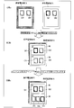
- FIG. 9 is a diagram illustrating an example of a screen displayed on the main display unit 13aA of the mobile phone 1A in the multi-layer state.
- the state a shown in FIG. 9 is a normal state before the layered state. As illustrated, in this state a, it is assumed that the mobile phone 1A holds the shared contents CA1 and CA2, and the mobile phone 1B holds the shared contents CB1 and CB2.
- the mobile phone 1A is stacked on the mobile phone 1B from the state a to be in a multilayered state (state b).
- state b the shared content display area WA in which the shared content held by the mobile phone 1A is displayed and the shared content held by the mobile phone 1B are displayed in the display area of the main display portion 13aA.
- Shared content display area WB is set. Then, shared content CA1 and CA2 are displayed in the shared content display area WA, and shared content CB1 and CB2 are displayed in the shared content display area WB.
- state b when the user performs a drag operation on the shared content CA1 from the shared content display area WA to the shared content display area WB, the state transitions to state c. As a result of this operation, the shared content CA1 is copied to the mobile phone 1B. Therefore, as shown in FIG. 9, in the state c, the shared content CA1 is displayed in the shared content display area WB in addition to the shared content CB1 and CB2. Is done.
- the display control unit 32 causes the shared content display area WA and the shared content display area to correspond to the upper and lower positional relationships of the mobile phone 1A and the mobile phone 1B in the multi-layer state.
- the WBs are arranged so as to have a vertical positional relationship in the display area of the main display unit 13a.
- the up and down directions are set, and along this, the shared content display area WA is on the upper side and the shared content display area WB is on the lower side. May be juxtaposed.
- the shared content display area WA and the shared content display area WB may be arranged in a state where a part of the shared content display area WB is superimposed below the shared content display area WA.
- the shared content display area WA and the shared content display area WB are made to correspond to the left and right positional relations in the display area of the main display unit 13a in correspondence with the upper and lower positional relations of the mobile phone 1A and the mobile phone 1B in the multi-layer state.
- Each may be arranged so as to be.
- the shared content display area WA and the shared content display area WB correspond to the mobile phone 1A and the mobile phone 1B, respectively, as shown in FIG.
- the display control unit 32 may display “A” indicating the mobile phone 1A in the shared content display area WA and display “B” indicating the mobile phone 1B in the shared content display area WB.
- the user name of the mobile phone 1A may be displayed.
- the frame color and / or background color of shared content display areas WA and WB are displayed in different colors.
- the color corresponding to the upper terminal and the color corresponding to the lower terminal may be set in advance, or the color may be set in advance for each user.
- a mobile phone is exemplified as the information processing apparatus of the present invention, but the present invention is not limited to this.
- the information processing apparatus of the present invention only needs to include a display unit and a communication unit.
- a PDA Personal Digital Assistant
- an electronic book terminal for example, a portable game machine, a digital camera, a digital TV, a notebook PC, portable music playback It may be a machine.
- the case where the two mobile phones 1 are the same model (size) is taken as an example, but the present invention is not limited to this.
- Different devices may be stacked, or devices of different sizes may be stacked.
- a portable game machine may be stacked on a digital TV display to share the content, or mobile phones having different display units or housing sizes may be stacked to share the content. It may be.
- the multi-layered state may be not only a state in which the information processing apparatus overlaps with the entire other information processing apparatus but also a state in which it overlaps with a part of the other information processing apparatus.
- hardware sensors and the like
- software multilayer state determination unit 31
- Mode 2 In the present embodiment, two mobile phones 1 are stacked to share content. However, the present invention is not limited to this, and all the mobile phones 1 that are in a multi-layered state are stacked by stacking three or more mobile phones 1. You may make it share contents.
- the main display portion 13a of the mobile phone 1A may be configured with 3D liquid crystal.
- the shared content display area WA in front of the shared content display area WB, it is possible to display corresponding to the state of each mobile phone 1 in a multi-layered state, and the user operates more intuitively. be able to.
- the content processing unit 35 moves and copies the shared content, but the present invention is not limited to this.
- the shared contents CA1, CA2, CB1, and CB2 of the mobile phones 1A and 1B are transmitted. You may make it possible to select it as an attached file.
- the content acquisition unit 43A may request and acquire the content from the mobile phone 1B when sending the mail.
- the content CB1 or CB2 is a moving image or music data
- the content may be reproduced on the mobile phone 1A by the user inputting a content reproduction instruction from the state shown in FIG. 9B.
- the game application is started from the state shown in FIG. 9B and used in the game application. You may enable it to share an item etc. in a game.
- electronic approval of the user of the mobile phone 1A or the user of the mobile phone 1B may be obtained by the user selecting content from the state shown in FIG. 9B.
- electronic approval of the user of the mobile phone 1B may be added to the content CA1 by selecting the content CA1.
- the multi-layer state is determined using the main display unit 13a and the sub display unit 13b, which are optical sensor liquid crystals, and communication is performed with Bluetooth.
- the determination method and the communication method are not limited thereto. is not.
- another mobile phone 1 may be detected by a magnetic sensor, a pressure sensor, or the like.
- any method can be used as long as it can determine the state in which the two mobile phones 1 are overlapped, and if the two mobile phones 1 can communicate in the multi-layer state, Any communication method may be used.
- a proximity sensor and an optical sensor are provided in place of the two optical sensor liquid crystals (the optical sensors 17a and 17b) in the first embodiment.
- the communication method of the two mobile phones 1 is the same Bluetooth as in the first embodiment. That is, the second embodiment is different from the first embodiment only in the multilayer state determination process, and the other processes are the same. In the following description, differences from the first embodiment will be mainly described in the second embodiment.
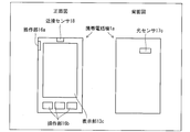
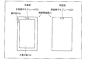
- the mobile phone 1a is provided with a proximity sensor 18, a display unit 13c, and an operation unit 16b on the front side, and an optical sensor 17c on the back side. Has been placed.
- the optical sensor 17c detects the light irradiated from the display part 13c of the other mobile telephone 1a
- the other mobile telephone 1a in which the mobile telephone 1a is on the back side is detected. It is determined that and are overlapping. Therefore, as shown in FIG. 12, the optical sensor 17c of the mobile phone 1aA is disposed at a position facing the display unit 13c of the other mobile phone 1aB when the mobile phone 1aA and the other mobile phone 1aB overlap each other.
- the arrangement and the size shown in FIG. 11 are not limited. That is, the size of the display unit 13c and the optical sensor 17c, the arrangement of the display unit 13c on the front side of the mobile phone 1a, and the arrangement of the photosensor 17c on the back side of the mobile phone 1a may be designed as appropriate.
- the proximity sensor 18 detects an object on the front side of the mobile phone 1a, thereby determining that the mobile phone 1a is in a state of being overlapped with another mobile phone 1a on the front side. Yes. Therefore, the proximity sensor 18 only needs to be able to detect whether there is an object on the front side of the mobile phone 1a, and the arrangement, size, and the like of the proximity sensor 18 may be appropriately designed.
- FIG. 10 is a block diagram illustrating an example of a main configuration of the mobile phone 1a.
- the mobile phone 1a includes a control unit 11a, a storage unit 12, a display unit 13c, a short-range wireless communication unit 14, a telephone network communication unit 15, an operation unit 16a, an operation unit 16b, an optical sensor 17c, and a proximity.
- a sensor 18 is provided.
- the mobile phone 1a may include members such as a voice input unit and a voice output unit, but these members are not shown because they are not related to the features of the invention.
- the display unit 13c displays an image in accordance with an instruction from the control unit 11a.
- the display unit 13c only needs to display an image in accordance with an instruction from the control unit 11a.
- an LCD liquid crystal display
- an organic EL display organic EL display
- a plasma display or the like can be applied.
- the operation unit 16b is for the user to input an instruction signal to the mobile phone 1a and operate the mobile phone 1a.
- the operation unit 16b may be configured with input devices such as a pointing device, a keypad, and operation buttons.
- a touch panel in which the operation unit 16b and the display unit 13c are integrated may be used.
- the optical sensor 17c detects light.
- light having a predetermined frequency emitted from the display unit 13c of another mobile phone 1a at a predetermined irradiation interval is detected.
- the proximity sensor 18 detects an object within a predetermined range from the proximity sensor 18.
- the proximity sensor 18 may be anything such as an inductive proximity sensor, a capacitive proximity sensor, or the like that detects the other mobile phone 1a.
- the control unit 11a performs various calculations by executing a program read from the storage unit 12 to a temporary storage unit (not shown), and comprehensively controls each unit included in the mobile phone 1a. .
- the control unit 11a reads communication application data to be placed from the storage unit 12. If the device overlaps with another mobile phone 1a after the communication application to be loaded is activated, the control unit 11a first acquires data from the other mobile phone 1a. Next, the control part 11a displays the data which the own apparatus and the other mobile telephone 1a hold
- control unit 11a includes a multi-layer state determination unit 31a, a display control unit 32, an input operation specifying unit 33, a communication connection control unit 34, and a content processing unit 35 as functional blocks.
- the CPU reads a program stored in a storage device realized by a ROM or the like into a temporary storage unit realized by a RAM or the like and executes the program. This can be achieved.
- the multi-layer state determination unit 31a determines whether or not the mobile phone 1a is in a state where it overlaps with another mobile phone 1a.
- the multilayer state determination unit 31a includes an upper terminal state determination unit 41a and a lower terminal state determination unit 42a.
- the upper terminal state determination unit 41a determines whether or not the own device is the upper terminal A (mobile phone 1aA) on the upper side of the other mobile phone 1a. In other words, the upper terminal state determination unit 41a determines whether or not there is another mobile phone 1a on the back side of the own device. In the present embodiment, the upper terminal state determination unit 41a determines whether or not the optical sensor 17c has detected predetermined light emitted from the display unit 13c, and the optical sensor 17c is irradiated from the display unit 13c. When the predetermined light is detected, the device is determined to be the upper terminal A. More specifically, the upper terminal state determination unit 41a determines whether or not the light sensor 17c detects predetermined light at a predetermined light receiving interval.
- the upper terminal state determination unit 41a determines that the own device is the upper terminal A, the upper terminal state determination unit 41a notifies the communication connection control unit 34 to that effect.
- the lower terminal state determination unit 42a determines whether or not the own device is the lower terminal B (mobile phone 1aB) on the lower side of the other mobile phone 1a. In other words, the lower terminal state determination unit 42a determines whether or not there is another mobile phone 1a on the front side of the own device. In the present embodiment, the lower terminal state determination unit 42a determines whether or not the proximity sensor 18 has detected an object, and determines that the own device is the lower terminal B when the proximity sensor 18 has detected an object. .
- the lower terminal state determination unit 42a determines that the own device is the lower terminal B
- the lower terminal state determination unit 42a notifies the display control unit 32 to that effect
- the display control unit 32 receives predetermined light from the display unit 13c. It is instructed to emit light at the light emission interval. Further, when the lower terminal state determination unit 42a determines that the own device is the lower terminal B, the lower terminal state determination unit 42a notifies the communication connection control unit 34 to that effect.
- the upper terminal state determination part 41a determines whether the optical sensor 17c detected the predetermined light irradiated from the display part 13c. It is. That is, the upper terminal state determination unit 41a determines whether the optical sensor 17c is facing the display unit 13c of the mobile phone 1aB, and light emitted from the display unit 13c (light detected by the optical sensor 17c) is It may be arbitrary and may be set appropriately in advance.
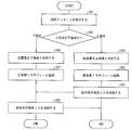
- FIG. 13 is a flowchart illustrating an example of the multilayer state determination process according to the second embodiment.
- the lower terminal state determination unit 42a of the mobile phone 1a determines whether or not the proximity sensor 18 has detected an object within a predetermined range (S51).
- the lower terminal state determination unit 42a determines that the device is the lower terminal B (S52), and notifies the display control unit 32 accordingly.
- the display control unit 32B causes the display unit 13cB to emit light having a predetermined frequency at a predetermined emission interval. That is, the display control unit 32B causes the display unit 13cB to blink and display (S53).
- the upper terminal state determination unit 41a determines whether or not the optical sensor 17c detects the blinking display of the display unit 13c (S54). When the optical sensor 17c detects blinking display (YES in S54), the upper terminal state determination unit 41a determines that the own device is the upper terminal A (S55). When the optical sensor 17c does not detect blinking display (NO in S54), the process returns to S51 again.
- the multi-layer state determination process is performed after starting the communication application to be mounted, but the present invention is not limited to this.
- the control unit 11a may activate a communication application to be placed, and the lower terminal state determination unit 42a may determine that the own device is the lower terminal B.
- the control unit 11a may activate a communication application to be placed, and the upper terminal state determination unit 41a may determine that the own device is the upper terminal A.
- the control unit 11a displays an error on the display unit 13c, and the multi-layer state Display a message that prompts you to do so, or close the communication application that is posted as a timeout.
- the upper terminal state determination unit 41aA continuously determines whether or not the optical sensor 17cA detects the blinking display of the display unit 13cB every predetermined period. If the optical sensor 17cA continuously detects blinking display, the upper terminal state determination unit 41aA determines that the multi-layer state is maintained (NO in S6A). On the other hand, when the optical sensor 17cA no longer detects the blinking display, the upper terminal state determination unit 41aA determines that the mobile phone 1aA has moved away from the mobile phone 1aB (YES in S6A), and ends the communication application carried by the control unit 11aA. (S7A).
- the lower terminal state determination unit 42aB continuously determines whether or not the proximity sensor 18B detects an object for each predetermined period. If the proximity sensor 18B continuously detects the object, the lower terminal state determination unit 42aB determines that the multi-layer state is maintained (NO in S6B). On the other hand, when the proximity sensor 18B no longer detects an object, the lower terminal state determination unit 42aB determines that the mobile phone 1aB has moved away from the mobile phone 1aA (YES in S6B), and ends the communication application carried by the control unit 11aB ( S7B).
- a camera is provided in place of the two photosensor liquid crystals (the photosensors 17a and 17b) in the first embodiment.
- the communication method of the two mobile phones 1 is the same Bluetooth as in the first embodiment, but the communication connection establishment process is different from that in the first embodiment. That is, the third embodiment is different from the first embodiment only in the multi-layer state determination process and the communication connection establishment process, and the other processes are the same. In the following description, differences of the third embodiment from the first embodiment will be mainly described.
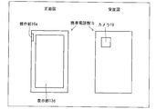
- a display unit 13d is arranged on the front side, and a camera 19 is arranged on the back side.
- the camera 19 takes a picture after the camera 19 recognizes the unique code displayed on the display unit 13d of the other mobile phone 1b.
- the camera 19 of the mobile phone 1bA is in a state before and when the mobile phone 1bA and another mobile phone 1bB are overlapped. It only needs to be disposed at a position facing the 1 bB display portion 13d, and is not limited to the arrangement and the size (shooting range) shown in FIG. That is, the size of the display unit 13d and the camera 19 (shooting range), the arrangement of the display unit 13d on the front side of the mobile phone 1b, and the arrangement of the camera 19 on the back side of the mobile phone 1b may be appropriately designed.
- FIG. 14 is a block diagram illustrating an example of a main part configuration of the mobile phone 1b.
- the mobile phone 1b includes a control unit 11b, a storage unit 12, a display unit 13d, a short-range wireless communication unit 14, a telephone network communication unit 15, an operation unit 16a, and a camera 19.
- the mobile phone 1b may include members such as a voice input unit and a voice output unit, but these members are not shown because they are not related to the features of the invention.
- the display unit 13d displays an image in accordance with an instruction from the control unit 11b.
- the display unit 13d only needs to display an image in accordance with an instruction from the control unit 11b.
- an LCD liquid crystal display
- an organic EL display organic EL display
- a plasma display or the like can be applied.
- the display unit 13d is provided with an operation unit 16c and is a touch panel.
- the operation unit 16c is for a user to input an instruction signal to the mobile phone 1b and operate the mobile phone 1b.
- the display unit 13d and the operation unit 16c may be separate bodies as in the second embodiment.
- the camera 19 acquires an image photographed by the image sensor as digital data.
- the control unit 11b performs various calculations by executing a program read from the storage unit 12 to a temporary storage unit (not shown), and comprehensively controls each unit included in the mobile phone 1b. .
- the control unit 11b reads communication application data to be placed from the storage unit 12. If the own device overlaps with another mobile phone 1b after starting the communication application to be placed, the control unit 11b first acquires data from the other mobile phone 1b. Next, the control part 11b displays the data which the own apparatus and the other mobile telephone 1b hold
- the control unit 11b includes a multi-layer state determination unit 31b, a display control unit 32, an input operation specifying unit 33, a communication connection control unit 34b, and a content processing unit 35 as functional blocks.
- the CPU stores a program stored in a storage device realized by a ROM or the like in a temporary storage unit realized by a RAM or the like. This can be realized by reading and executing.
- the multi-layer state determination unit 31b determines whether or not the mobile phone 1b is in a state where it overlaps with another mobile phone 1b.
- the multilayer state determination unit 31b includes an upper terminal state determination unit 41b and a lower terminal state determination unit 42b.
- the upper terminal state determination unit 41b determines whether or not the own device is the upper terminal A (mobile phone 1bA) above the other mobile phone 1b. In other words, the upper terminal state determination unit 41b determines whether there is another mobile phone 1b on the back side of the own device. In the present embodiment, the upper terminal state determination unit 41b determines whether the camera 19 has recognized the unique code displayed on the display unit 13d of the other mobile phone 1b, and further, the image acquired by the camera 19 Determine if has become dark. The upper terminal state determination unit 41b determines that the device is the upper terminal A when the camera 19 recognizes the unique code and the image acquired by the camera 19 becomes dark thereafter. More specifically, the upper terminal state determination unit 41b determines whether or not the image captured by the camera 19 includes a unique code. If the unique code is included, the image captured by the camera 19 is then captured. It is determined whether or not the luminance of the image has become a predetermined value or less.
- the upper terminal state determination unit 41b determines that the own device is the upper terminal A, the upper terminal state determination unit 41b notifies the communication connection control unit 34b accordingly.
- the lower terminal state determination unit 42b determines whether or not the own device is the lower terminal B (mobile phone 1bB) below the other mobile phone 1b. In other words, the lower terminal state determination unit 42b determines whether or not there is another mobile phone 1b on the front side of the own device. In the present embodiment, the lower terminal state determination unit 42b determines whether or not the unique code has been transmitted from another mobile phone 1b via the short-range wireless communication unit 14, and when the unique code is received, The own device is determined to be the lower terminal B.
- the lower terminal state determination unit 42b determines that the own device is the lower terminal B, the lower terminal state determination unit 42b notifies the communication connection control unit 34b accordingly.
- the unique code displayed on the display unit 13d may be a one-dimensional or two-dimensional barcode or a predetermined image.
- the unique code may be determined in advance between the two mobile phones 1b, and may be set arbitrarily.
- the communication connection control unit 34b establishes a communication connection between the short-range wireless communication unit 14 and the short-range wireless communication unit 14 of another mobile phone 1b.
- the communication connection control unit 34b starts waiting for communication connection after the communication application to be mounted is activated.
- the communication connection control unit 34b receives a notification that the own device is the upper terminal A from the upper terminal state determination unit 41, the communication connection control unit 34b ends the waiting for communication connection.
- the communication connection control unit 34b transmits a communication start signal and a unique code to the mobile phone 1bB via the short-range wireless communication unit 14.
- the communication connection control unit 34bA receives the terminal ID from the mobile phone 1bB
- the communication connection control unit 34bA transmits the terminal ID of its own device to the mobile phone 1bB via the short-range wireless communication unit 14.
- the communication connection control unit 34b starts waiting for a communication connection after the communication application to be mounted is activated.
- the communication connection control unit 34b receives the communication start signal and the unique code and receives a notification from the lower terminal state determination unit 42 that the own device is the lower terminal B, the communication connection control unit 34b passes the short-range wireless communication unit 14 to The terminal ID of its own device is transmitted to 1A.
- FIG. 17 is a flowchart illustrating an example of a multi-layer state determination process and a communication connection establishment process in the third embodiment.
- the control unit 11b instructs the display control unit 32 to display the unique code on the display unit 13d (S61).
- the communication connection control unit 34b activates the short-range wireless communication unit 14 and waits for communication connection (S62). Further, the control unit 11b activates the camera 19 (S63).
- the upper terminal state determination unit 41b determines whether or not the camera 19 has recognized the unique code (S64). If a unique code is included in the image captured by the camera 19 (YES in S64), the upper terminal state determination unit 41b then determines whether the image captured by the camera 19 has become dark (S65). . The upper terminal state determination unit 41b determines that the device is the upper terminal A when the camera 19 recognizes the unique code and the image captured by the camera 19 becomes dark thereafter (YES in S65) ( S66).
- the upper terminal state determination unit 41b determines that the own device is the upper terminal A, the upper terminal state determination unit 41b notifies the communication connection control unit 34b accordingly.
- the communication connection control unit 34bA receives the notification from the upper terminal state determination unit 41bA, the communication connection control unit 34bA ends standby for communication connection, and transmits a communication start signal and a unique code to the mobile phone 1bB via the short-range wireless communication unit 14A. (S67).
- the communication connection control unit 34b communicates with another mobile phone 1b. It waits for a unique code to be transmitted together with the connection start signal (S68).
- the process returns to S64 again.
- the communication connection control unit 34b receives the communication connection start signal and the unique code (YES in S68)
- it notifies the lower terminal state determination unit 42b to that effect.
- the lower terminal state determination unit 42b that has received the notification determines that the own device is the lower terminal B (S69).
- the communication connection control unit 34bB transmits the terminal ID of the own device (the mobile phone 1bB) to the mobile phone 1bA (S70).
- the communication connection control unit 34bA transmits the terminal ID of the own device (the mobile phone 1bA) to the mobile phone 1bB (S71).
- the communication connection control unit 34bB receives the terminal ID from the mobile phone 1bA and completes the establishment of the communication connection, and the communication connection control unit 34bA receives the response to the terminal ID transmission and the establishment of the communication connection is completed. Make sure.
- the control unit 11b displays an error on the display unit 13d, Display a message that prompts you to enter a multi-layered state, or end the communication app that you want to post if timed out.
- Multilayer state maintenance judgment processing In the third embodiment, the process for determining whether or not the two mobile phones 1b in S6A and S6B shown in FIG. 4 maintain the multi-layer state is also different from that in the first embodiment.
- the multilayer state maintenance determination process of this embodiment will be described in detail.
- the upper terminal state determination unit 41bA continuously determines whether the image captured by the camera 19 remains dark every predetermined period. If the upper terminal state determination unit 41bA continuously detects that the image captured by the camera 19 remains dark, the upper terminal state determination unit 41bA determines that the multi-layer state is maintained (NO in S6A). On the other hand, when the image taken by the camera 19 is not dark, that is, when the brightness of the image taken by the camera 19 is equal to or higher than a predetermined value, the upper terminal state determination unit 41bA moves away from the mobile phone 1bB. (YES in S6A). And the communication application which control part 11bA carries is complete
- the upper terminal state determination unit 41bA determines that the mobile phone 1bA is away from the mobile phone 1bB, the upper terminal state determination unit 41bA notifies the communication connection control unit 34bA to that effect. Receiving the notification, the communication connection control unit 34bA notifies the mobile phone 1bB that it is no longer in the multi-layer state via the short-range wireless communication unit 14.
- the lower terminal state determination unit 42bB continuously determines, every predetermined period, whether or not the communication connection control unit 34bB has received a notification indicating that the mobile phone 1bA is not in the multi-layer state. If the communication connection control unit 34bB does not receive the notification, the lower terminal state determination unit 42bB determines that the multi-story state is maintained (NO in S6B). On the other hand, when the communication connection control unit 34bB receives the notification, the lower terminal state determination unit 42bB determines that the mobile phone 1bB has moved away from the mobile phone 1bA (YES in S6B), and ends the communication application carried by the control unit 11bB. (S7B).
- the multi-layer state is determined using the two photosensor liquid crystals (the optical sensors 17a and 17b). However, in the fourth embodiment, whether or not the multi-layer state is determined based on a user operation. And determine whether the device is the upper terminal A or the lower terminal B.
- communication is performed using Bluetooth.
- communication connection is performed using bidirectional infrared communication such as IrDA. That is, the fourth embodiment is different from the first embodiment only in the multilayer state determination process and the communication connection establishment process, and the other processes are the same.
- differences of the fourth embodiment from the first embodiment will be mainly described.
- a front side IR module 22a is arranged on the front side
- a back side IR module 22b is arranged on the back side.
- the back side IR module 22b of the mobile phone 1cA that is the upper terminal A and the front side IR module 22a of the mobile phone 1cB that is the lower terminal B establish communication connection.
- the front side IR module 22a and the back side IR module 22b only have to be arranged at positions facing each other in a state where the mobile phone 1cA and the other mobile phone 1cB are overlapped.
- the arrangement shown in FIG. 19 and the size thereof are not limited. That is, the arrangement and size of the front side IR module 22a and the back side IR module 22b may be designed as appropriate.
- FIG. 18 is a block diagram illustrating an example of a main configuration of the mobile phone 1c.
- the mobile phone 1c includes a control unit 11c, a storage unit 12, a display unit 13d, an infrared communication unit 21, a telephone network communication unit 15, and an operation unit 16a.
- the mobile phone 1c may include members such as a voice input unit and a voice output unit, but these members are not shown because they are not related to the features of the invention.
- the display unit 13d displays an image in accordance with an instruction from the control unit 11c.
- the display unit 13d only needs to display an image in accordance with an instruction from the control unit 11c.
- an LCD liquid crystal display
- an organic EL display organic EL display
- a plasma display or the like can be applied.
- the display unit 13d is provided with an operation unit 16c and is a touch panel.
- the operation unit 16c is for the user to input an instruction signal to the mobile phone 1c and operate the mobile phone 1c.
- the display unit 13d and the operation unit 16c may be separate bodies as in the second embodiment.
- the infrared communication unit 21 communicates with other devices (for example, other mobile phones 1c and the like) by infrared wireless communication means, and exchanges data according to instructions from the control unit 11c.
- the infrared communication unit 21 includes a front-side IR module 22a disposed on the front side of the mobile phone 1c and a back-side IR module 22b disposed on the back side of the mobile phone 1c.
- the control unit 11c performs various calculations by executing a program read from the storage unit 12 to a temporary storage unit (not shown), and comprehensively controls each unit included in the mobile phone 1c. .
- the control unit 11c reads communication application data to be placed from the storage unit 12. If the self-apparatus overlaps with another mobile phone 1c after the communication application to be loaded is activated, the control unit 11c first acquires data from the other mobile phone 1c. Next, the control part 11c displays the data which an own apparatus and the other mobile telephone 1c hold
- control unit 11c includes a multi-layer state determination unit 31c, a display control unit 32, an input operation specifying unit 33, a communication connection control unit 34c, and a content processing unit 35 as functional blocks.
- the CPU stores a program stored in a storage device realized by a ROM or the like in a temporary storage unit realized by a RAM or the like. This can be realized by reading and executing.
- the multi-layer state determination unit 31c determines whether or not the mobile phone 1c is in a state where it overlaps with another mobile phone 1c.
- the multilayer state determination unit 31c includes an upper terminal state determination unit 41c and a lower terminal state determination unit 42c.
- the upper terminal state determination unit 41c determines whether or not the own device is the upper terminal A (mobile phone 1cA) on the upper side of the other mobile phone 1c. In other words, the upper terminal state determination unit 41c determines whether or not there is another mobile phone 1c on the back side of the own device. In the present embodiment, the upper terminal state determination unit 41c determines whether or not the own device is the upper terminal A based on a user operation instruction input to the own device using the operation unit 16a or the operation unit 16c. To do. More specifically, the upper terminal state determination unit 41c determines that the own device is the upper terminal A when the user sets the own device as the upper terminal.
- the upper terminal state determination unit 41c determines that the own device is the upper terminal A, the upper terminal state determination unit 41c notifies the communication connection control unit 34c to that effect.
- the lower terminal state determination unit 42c determines whether or not the own device is the lower terminal B (mobile phone 1cB) on the lower side of the other mobile phone 1c. In other words, the lower terminal state determination unit 42c determines whether there is another mobile phone 1c on the front side of the own device. In the present embodiment, the lower terminal state determination unit 42c determines whether or not the own device is the lower terminal B based on a user operation instruction input to the own device using the operation unit 16a or the operation unit 16c. To do. More specifically, the lower terminal state determination unit 42c determines that the own device is the lower terminal B when the user sets the own device as the lower terminal.
- the lower terminal state determination unit 42c does not set whether the own device is the upper terminal or the lower terminal from the user, and when the communication connection control unit 34c receives the terminal ID from another mobile phone 1c, the lower terminal state determination unit 42c The terminal B may be determined.
- the lower terminal state determination unit 42c determines that the own device is the lower terminal B, the lower terminal state determination unit 42c notifies the communication connection control unit 34c to that effect.
- the communication connection control unit 34c establishes a communication connection between the infrared communication unit 21 of its own device and the infrared communication unit 21 of another mobile phone 1c.
- the communication connection control unit 34c receives a notification that the own device is the upper terminal A from the upper terminal state determination unit 41c, the communication connection control unit 34c activates the back side IR module 22b, and the terminal ID of the own device via the back side IR module 22b. Send.
- the communication connection control unit 34c receives a notification that the own device is the lower terminal B from the lower terminal state determination unit 42c, the communication connection control unit 34c activates the front IR module 22a, and the own device via the front IR module 22a. Send the terminal ID.
- the communication connection control unit 34 may perform control so that the other is not activated.
- the communication connection control unit 34c may activate the front side IR module 22a after activation of the communication application to be mounted.
- the communication connection control unit 34c stops the front IR module 22a and starts the rear IR module 22b.
- the communication connection control part 34c transmits terminal ID of an own apparatus via the back side IR module 22b.
- the communication connection control unit 34c activates the front IR module 22a after starting the communication application to be placed, receives the terminal ID from the other mobile phone 1c, and then receives the terminal ID of the own device via the front IR module 22a.
- the terminal ID may be transmitted.
- FIG. 21 is a flowchart illustrating an example of an overlay state determination process and a communication connection establishment process according to the fourth embodiment.
- FIG. 22 is a flowchart illustrating another example of the multi-layer state determination process and the communication connection establishment process in the fourth embodiment.
- the control unit 11c sets the user whether the display device 13d is the upper terminal A or the lower terminal B to the display control unit 32.
- the message to be displayed is instructed to be displayed (S81).
- the input operation specifying unit 33 waits for an instruction from the user indicating whether the terminal is the upper terminal A or the lower terminal B (S82).
- the input operation specifying unit 33 notifies the upper terminal state determining unit 41c to that effect.
- the upper terminal state determination unit 41c determines that the own device is the upper terminal A based on a user operation (S83).
- the control unit 11c instructs the display control unit 32 to display on the display unit 13d a message that prompts the user to place the device on another mobile phone 1c.
- the upper terminal state determination unit 41c notifies the communication connection control unit 34c that the own device is the upper terminal A. Receiving the notification, the communication connection control unit 34c activates the back side IR module 22b (S84), and transmits the terminal ID of the own device via the back side IR module 22b (S85).
- the input operation specifying unit 33 notifies the lower terminal state determining unit 42c to that effect.
- the lower terminal state determination unit 42c determines that the own device is the lower terminal B based on a user operation (S86).
- the control unit 11c instructs the display control unit 32 to display a message prompting the user to place another mobile phone 1c on the own device on the display unit 13d.
- the lower terminal state determination unit 42c notifies the communication connection control unit 34c that the own device is the lower terminal B. Receiving the notification, the communication connection control unit 34c activates the front IR module 22a (S87), and transmits the terminal ID of the own device via the front IR module 22a (S88).
- the communication connection control unit 34c confirms that the transmission of the terminal ID of its own device is completed and has received the terminal ID of the other mobile phone 1c, and completes establishment of the communication connection.
- the communication connection control unit 34c starts the front IR module 22a (S91). Thereafter, the control unit 11c instructs the display control unit 32 to display a message on the display unit 13d that causes the user to set whether or not to set the own apparatus to the upper terminal A. Then, the input operation specifying unit 33 waits for an instruction to be the upper terminal A from the user (S92).
- the input operation specifying unit 33 notifies the upper terminal state determining unit 41c to that effect.
- the upper terminal state determination unit 41c determines that the own device is the upper terminal A based on a user operation (S93).
- the control unit 11c instructs the display control unit 32 to display on the display unit 13d a message that prompts the user to place the device on another mobile phone 1c.
- the upper terminal state determination unit 41c notifies the communication connection control unit 34c that the own device is the upper terminal A. Receiving the notification, the communication connection control unit 34c activates the back side IR module 22b (S94), and transmits the terminal ID of its own device via the back side IR module 22b (S95).
- the communication connection control unit 34c receives the terminal ID from the other mobile phone 1c via the front IR module 22a. Wait for transmission (S96).
- the process returns to S92 again.
- the communication connection control unit 34c notifies the lower terminal state determination unit 42c to that effect. Receiving the notification, the lower terminal state determination unit 42c determines that the own device is the lower terminal B (S97). And the communication connection control part 34c transmits terminal ID of an own apparatus via the front side IR module 22a (S98).
- the communication connection control unit 34c confirms that the transmission of the terminal ID of its own device is completed and has received the terminal ID of the other mobile phone 1c, and completes establishment of the communication connection.
- the control unit 11c displays an error in the display unit 13d. , And a message prompting the user to set the terminal A again is displayed, or the communication application to be posted is terminated when time-out occurs.
- the upper terminal state determination unit 41cA determines that the state is maintained (NO in S6A).
- the communication connection control unit 34cA polls another mobile phone 1cB via the back side IR module 22bA.
- the upper terminal state determination unit 41cA determines that the mobile phone 1cA has moved away from the mobile phone 1cB (YES in S6A), and ends the communication application carried by the control unit 11cA (S7A). .
- FIGS. 23 and 24 are cross-sectional views in side view of the schematic structure of the casing of the mobile phone.
- FIG. 25 is a cross-sectional view in side view of the schematic structure of the casings of two mobile phones in a multi-layered state.
- the shape of the casing of the mobile phone 1c is a substantially rectangular parallelepiped
- the front IR module 22a is arranged on the front side of the casing of the mobile phone 1c
- the rear side is on the back side.
- the side IR module 22b is arranged, the shape of the casing of the mobile phone 1c and the positions of the front side IR module 22a and the back side IR module 22b on the casing are not limited to this.
- a mortar-shaped recess 51 is provided in each of a part of the front side and the back side of a substantially rectangular parallelepiped casing, and the front IR module 22a and the back side are provided at the bottom of the recess 51.
- An IR module 22b may be arranged.
- the IR module is arranged on the surface of the casing as shown in FIG. 23, and it is assumed that the distance between the two IR modules is extremely short (when the two IR modules are almost in contact). Not. However, in the present invention, communication is performed in a state where the two mobile phones 1c are overlapped with each other, and therefore the case where the distance between the two IR modules becomes almost zero is considered. In this case, with the arrangement of the IR modules as shown in FIG. 23, even if the two mobile phones 1c are in a multi-layered state, the back side IR module 22bA and the front side IR module 22aB may not be able to communicate with each other. is there.
- the cellular phone 1cA and the cellular phone 1cB are in contact with each other in a multilayered state, but the back side IR module 22bA and the front side IR module 22aB are not in contact with each other.
- a communication path cannot be secured and communication with each other is not possible.
- the IR module as shown in FIG. 23, even if the two mobile phones 1c are in a multi-layered state, they cannot communicate with each other with a slight deviation.
- the IR module when the IR module is disposed at the bottom of the recess 51, as shown in FIG. 25, even if the cellular phone 1dA and the cellular phone 1dB are in a state of being overlaid, Can be secured and can communicate with each other.
- the degree of freedom of the communication path between the IR modules is increased, and the cellular phone 1d is somewhat Even if they are shifted and are in a multi-layered state, they can communicate with each other.
- the shape of the recessed part 51 is not restricted to a mortar shape, What is necessary is just a concave shape. Further, the recess 51 may be covered with an IR lens so that the entire surface of the casing of the mobile phone 1d is a flat plane.
- FIG. 26 is a cross-sectional view in side view of the schematic structure of the casings of two mobile phones in a multilayered state.
- the casings of the cellular phones 1eA and 1eB are configured by a substantially rectangular parallelepiped base 52 and a substantially rectangular parallelepiped extending portion 53 extending from one end of the base 52 in the vertical direction on the front side.
- the surface on the multi-end side of the base portion 52 is referred to as an inner surface
- the surface on one end side of the base portion 52 is referred to as an outer surface.
- the front-side IR module 22a is arranged on the inner surface on the distal end side (front side) of the extending portion 53, and the back side is on the outer surface on the bottom side of one end of the base portion 52
- An IR module 22b is arranged.
- the cross section of the side view of the mobile phone 1eA and 1eB is L-shaped, when the user puts the two mobile phones 1e into a multi-layered state, the two easily and accurately Mobile phone 1e can be stacked. Therefore, the two mobile phones 1e can be reduced from being overlapped with each other in the multi-layered state, so that the state in which the two mobile phones 1e cannot communicate in the multi-layered state can be reduced.
- the mobile phone 1 is a mobile phone provided with the main display portion 13a, and that there is another mobile phone 1 on the back side opposite to the display surface side where the main display portion 13a is arranged.
- the detected upper terminal state determination unit 41 and the upper terminal state determination unit 41 detect another mobile phone 1
- content identification information indicating content stored in the other mobile phone 1 is received from the other mobile phone 1.
- a first display area corresponding to the own device and a second display area corresponding to the other mobile phone 1 are set and stored in the own device. Content to be displayed in the first display area, and based on the content identification information acquired by the content acquisition unit 43, the content stored in the other mobile phone 1 is displayed in the second display area.
- a display control unit 32 for.
- An information processing apparatus includes an input unit that receives an operation input from a user, and an operation input that moves the operation display information displayed in one of the first display area and the second display area to the other. Is input by the input means, the content specified by the operation display information is moved or moved from the information processing device corresponding to the one display region to the information processing device corresponding to the other display region. It is preferable to further include a moving duplicating means for duplicating.
- the moving duplicating means receives an operation input for moving the operation display information displayed in one of the first display area and the second display area to the other by the input means. Then, the content specified by the display information for operation is moved or copied from the information processing apparatus corresponding to the one display area to the information processing apparatus corresponding to the other display area.
- the user performs an operation of moving the content displayed in one of the first display area and the second display area to the other display area, so that the information processing apparatus moves from one information processing apparatus to the other information processing apparatus.
- the display control unit arranges the first display area and the second display area so that the display area of the display unit has a vertical or horizontal positional relationship. Is preferred.
- the display control means arranges the first display area and the second display area so as to have a vertical or horizontal positional relationship in the display area of the display unit. That is, for example, the content stored in the information processing device on the upper side is displayed in the first display area on the upper side of the display unit, and the content stored in the other information processing device on the lower side is displayed below the display unit.
- the vertical direction may be set, and the first display area may be arranged side by side so that the first display area is on the upper side and the second display area is on the lower side.
- the first display area and the second display area may be arranged in a state where a part of the second display area is superimposed on the bottom.
- the content stored in the information processing device on the upper side is displayed in the first display area on the left side of the display unit, and the content stored in the other information processing device on the lower side is displayed on the right side of the display unit.
- the second display area In the second display area.
- the left and right directions are set, and the first display area may be arranged on the left side and the second display area on the right side.
- the first display area and the second display area may be arranged in a state where a part of the second display area is superimposed below.
- the vertical positional relationship between the two information processing devices and the vertical or horizontal positional relationship between the contents displayed on the display unit correspond to each other, so that the user can intuitively understand the content stored in the two information processing devices. Can be distinguished and recognized.
- the information processing system preferably includes one each of the first information processing apparatus and the second information processing apparatus.
- the first information processing apparatus is an information processing apparatus including a display unit, and detects that there is another information processing apparatus on the back side opposite to the display surface side on which the display unit is arranged.
- the back side device detecting means and the back side device detecting means detect another information processing device, content identification information indicating the content stored in the other information processing device is acquired from the other information processing device.
- the operation display information for identifying the at least comprising the information processing apparatus and display control means for displaying on the second display area.
- the second information processing apparatus is an information processing apparatus including a display unit, and a surface-side device detection unit that detects that there is another information processing apparatus on the display surface side where the display unit is disposed.
- the information processing device includes at least content identification information transmitting means for transmitting content identification information indicating the content stored in the device to the other information processing device.
- the information processing system has the same effect as the information processing device.
- each block of the cellular phones 1, 1a, 1b, and 1c, particularly the control units 11, 11a, 11b, and 11c, may be configured by hardware logic, or realized by software using a CPU as follows. May be.
- the cellular phones 1, 1a, 1b, and 1c include a CPU (central processing unit) that executes instructions of a control program for realizing each function, a ROM (read only memory) that stores the program, and a RAM that expands the program (Random access memory), a storage device (recording medium) such as a memory for storing the program and various data.
- An object of the present invention is to make it possible to read the program code (execution format program, intermediate code program, source program) of the control program of the mobile telephones 1, 1a, 1b and 1c, which is software that realizes the functions described above, with a computer. This can also be achieved by supplying the recorded recording medium to the mobile phone 1, 1a, 1b and 1c, and reading out and executing the program code recorded on the recording medium by the computer (or CPU or MPU). .
- Examples of the recording medium include tapes such as magnetic tapes and cassette tapes, magnetic disks such as floppy (registered trademark) disks / hard disks, and disks including optical disks such as CD-ROM / MO / MD / DVD / CD-R.
- Card system such as IC card, IC card (including memory card) / optical card, or semiconductor memory system such as mask ROM / EPROM / EEPROM / flash ROM.
- the mobile phones 1, 1a, 1b and 1c may be configured to be connectable to a communication network, and the program code may be supplied via the communication network.
- the communication network is not particularly limited.
- the Internet intranet, extranet, LAN, ISDN, VAN, CATV communication network, virtual private network, telephone line network, mobile communication network, satellite communication. A net or the like is available.
- the transmission medium constituting the communication network is not particularly limited.
- infrared rays such as IrDA and remote control, Bluetooth ( (Registered trademark), 802.11 wireless, HDR, mobile phone network, satellite line, terrestrial digital network, and the like can also be used.
- the present invention can also be realized in the form of a computer data signal embedded in a carrier wave in which the program code is embodied by electronic transmission.
- the present invention can be used for an information processing apparatus including a display unit such as a mobile phone.
- Mobile phone information processing apparatus 13a Main display section (display section) 13c, 13d Display unit (display unit) 16a, 16b, 16c Operation unit (input means) 17a Optical sensor (input means) 32 Display control unit (display control means) 41, 41a, 41b, 41c Upper terminal state determination unit (rear side device detection means) 42, 42a, 42b, 42c Lower terminal state determination unit (surface side device detection means) 43 Content acquisition unit (content identification information acquisition means, moving duplication means) 44 Content transmission unit (content identification information transmission means, moving duplication means)
Landscapes
- Engineering & Computer Science (AREA)
- Human Computer Interaction (AREA)
- Computer Networks & Wireless Communication (AREA)
- Signal Processing (AREA)
- Telephone Function (AREA)
Abstract
携帯電話機(1)は、近接する他の携帯電話機(1)を検出すると、他の携帯電話機(1)が記憶するコンテンツを示すコンテンツ識別情報を取得し、自装置が記憶するコンテンツを主表示部(13a)の第1表示領域に表示し、上記コンテンツ識別に基づいて、他の携帯電話機(1)が記憶するコンテンツを主表示部(13a)の第2表示領域に表示する。
Description
本発明は、自装置が記憶する情報および他装置が記憶する情報を処理する情報処理装置、情報処理装置の制御方法、制御プログラムおよび記録媒体に関するものである。
近年、携帯電話機等の携帯情報端末には、高性能の演算処理装置や大容量の記憶装置、写真や動画を撮影可能なカメラ等が搭載されており、携帯情報端末が扱うコンテンツ(連絡先情報、テキスト、画像、動画、音楽情報等)の種類やデータ量が増えてきている。そのため、ユーザは、多種多量の各種コンテンツを携帯情報端末に保有しており、ユーザ同士でそれぞれが保有するコンテンツを交換することが行われている。
ここで、ユーザがコンテンツを装置間で交換する際に、簡単な操作で装置間のデータの送受信が実行できることが望まれている。従来、装置間でデータの送受信を行うシステムとして、例えば、次のような技術がある。
特許文献1には、IDタグリーダを備える端末装置であって、ユーザが保持するIDタグを検出し、検出したユーザの端末装置に、IDタグ検出期間中に操作されたデータを送信する端末装置が記載されている。
特許文献2には、受光素子を備える表示部を搭載した携帯電話機であって、複数の携帯電話機の表示部を対向させて、光通信によりデータを送受信する携帯電話機が記載されている。
特許文献3には、側面にセンサを備える携帯電話機であって、複数の携帯電話機の側面を接触させた状態で、それぞれの携帯電話機が記憶するコンテンツを、それぞれの携帯電話機で各種処理を行う技術が記載されている。
また、技術水準を示す文献として特許文献4および5を例示する。
特許文献4には、他の通信端末と画像およびメッセージを送受信して、画像を表示する通信端末を複数含む通信システムにおいて、通信端末間の距離が近い場合、ユーザの撮影画像を通信端末に表示し、通信端末間の距離が遠い場合、ユーザのアバタ画像を通信端末に表示する技術が記載されている。
特許文献5には、他の機器の位置を検出する位置検出部と表示部とを備える機器を複数含む表示システムにおいて、1つの表示部より大きなサイズの表示データを、各機器の位置関係に基づいて、各機器の表示部で連続的に表示する技術が記載されている。
しかしながら、上述のような従来技術では、装置間のデータの送受信を直感的に行うという点ではまだ不十分である。
例えば、特許文献3では、データを共有する場合、携帯電話機を横並びにしているが、本発明者は、2端末間のデータが共有している状態をより直感的に表す状態が他にあると考える。
本発明は、上記の問題点に鑑みてなされたものであり、その目的は、装置間のデータの共有を、ユーザがより直感的に、より簡単に操作可能な情報処理装置、情報処理装置の制御方法、制御プログラムおよび記録媒体を実現することにある。
本発明に係る情報処理装置は、上記課題を解決するために、表示部を備える情報処理装置であって、上記表示部が配置されている表示面側とは反対の背面側に他の情報処理装置があることを検出する背面側装置検出手段と、上記背面側装置検出手段が他の情報処理装置を検出すると、上記他の情報処理装置から、上記他の情報処理装置が記憶するコンテンツを示すコンテンツ識別情報を取得するコンテンツ識別情報取得手段と、上記表示部の表示領域に、自装置に対応する第1表示領域と、上記他の情報処理装置に対応する第2表示領域とを設定し、自装置が記憶するコンテンツを特定する操作用表示情報を上記第1表示領域に表示するとともに、上記コンテンツ識別情報取得手段の取得したコンテンツ識別情報に基づいて、上記他の情報処理装置が記憶するコンテンツを特定する操作用表示情報を上記第2表示領域に表示する表示制御手段とを備えることを特徴としている。
本発明に係る情報処理装置の制御方法は、上記課題を解決するために、表示部を備える情報処理装置の制御方法であって、上記表示部が配置されている表示面側とは反対の背面側に他の情報処理装置があることを検出する背面側装置検出ステップと、上記背面側装置検出ステップにおいて他の情報処理装置を検出された後、上記他の情報処理装置から、上記他の情報処理装置が記憶するコンテンツを示すコンテンツ識別情報を取得するコンテンツ識別情報取得ステップと、上記表示部の表示領域に、自装置に対応する第1表示領域と、上記他の情報処理装置に対応する第2表示領域とを設定し、自装置が記憶するコンテンツを特定する操作用表示情報を上記第1表示領域に表示するとともに、上記コンテンツ識別情報取得手段の取得したコンテンツ識別情報に基づいて、上記他の情報処理装置が記憶するコンテンツを特定する操作用表示情報を上記第2表示領域に表示する表示制御ステップとを含むことを特徴としている。
上記の構成によれば、上記背面側装置検出手段は、上記表示部が配置されている表示面側とは反対の背面側に他の情報処理装置があることを検出し、上記コンテンツ識別情報取得手段は、上記背面側装置検出手段が他の情報処理装置を検出すると、上記他の情報処理装置から、上記他の情報処理装置が記憶するコンテンツを示すコンテンツ識別情報を取得し、上記表示制御手段は、上記表示部の表示領域に、自装置に対応する第1表示領域と、上記他の情報処理装置に対応する第2表示領域とを設定し、自装置が記憶するコンテンツを特定する操作用表示情報を上記第1表示領域に表示するとともに、上記コンテンツ識別情報取得手段の取得したコンテンツ識別情報に基づいて、上記他の情報処理装置が記憶するコンテンツを特定する操作用表示情報を上記第2表示領域に表示する。
そのため、ユーザは、上記情報処理装置の背面側に上記他の情報処理装置を置くことによって、上記情報処理装置の表示部に、上記情報処理装置の記憶するコンテンツと、上記他の情報処理装置が記憶するコンテンツとを、分けて表示することができる。すなわち、ユーザは、上記他の情報処理装置の上に上記情報処理装置を重ねることによって、上記情報処理装置の記憶するコンテンツだけではなく、上記情報処理装置の下にある上記他の情報処理装置が記憶するコンテンツを認識することができる。
従って、ユーザは、他のユーザが所持する他の情報処理装置に自身が所持する情報処理装置を重ねるという、直感的かつ簡単な操作で、他のユーザの保有するコンテンツを知ることができるという効果を奏する。
ここで、2つの情報処理装置が記憶するコンテンツを共有している状態を直感的に表す2つの情報処理装置が重なっている状態(一体となっている状態)であっても、上側の情報処理装置の表示部に2つの情報処理装置が記憶するコンテンツの両方を分類して表示することにより、なんら不自由なく2つの情報処理装置の記憶するコンテンツをユーザが認識することができる。
本発明に係る情報処理装置は、上記課題を解決するために、表示部を備える情報処理装置であって、上記表示部が配置されている表示面側に他の情報処理装置があることを検出する表面側装置検出手段と、上記表面側装置検出手段が他の情報処理装置を検出すると、上記他の情報処理装置に、自装置の記憶するコンテンツを示すコンテンツ識別情報を送信するコンテンツ識別情報送信手段とを備えることを特徴としている。
本発明に係る情報処理装置の制御方法は、上記課題を解決するために、表示部を備える情報処理装置の制御方法であって、上記表示部が配置されている表示面側に他の情報処理装置があることを検出する表面側装置検出ステップと、上記表面側装置検出ステップにおいて他の情報処理装置を検出された後、上記他の情報処理装置に、自装置の記憶するコンテンツを示すコンテンツ識別情報を送信するコンテンツ識別情報送信ステップとを含むことを特徴としている。
上記の構成によれば、上記表面側装置検出手段は、上記表示部が配置されている表示面側に他の情報処理装置があることを検出し、上記コンテンツ識別情報送信手段は、上記表面側装置検出手段が他の情報処理装置を検出すると、上記他の情報処理装置に、自装置の記憶するコンテンツを示すコンテンツ識別情報を送信する。
そのため、ユーザは、上記情報処理装置の表示面側に上記他の情報処理装置を置くことによって、上記情報処理装置が記憶するコンテンツを上記他の情報処理装置に通知することができる。すなわち、ユーザは、上記情報処理装置の上に上記他の情報処理装置を重ねることによって、上記他の情報処理装置に上記情報処理装置の記憶するコンテンツを通知することができる。
従って、ユーザは、自身が所持する情報処理装置に他のユーザが所持する他の情報処理装置を重ねるという、直感的かつ簡単な操作で、他のユーザに自身が保有するコンテンツを知らせることができるという効果を奏する。
なお、上記情報処理装置は、コンピュータによって実現してもよく、この場合には、コンピュータを上記情報処理装置の各手段として動作させることにより、上記情報処理装置をコンピュータにて実現させる制御プログラム、及びそれを記録したコンピュータ読み取り可能な記録媒体も本発明の範疇に入る。
以上のように、本発明に係る情報処理装置は、上記表示部が配置されている表示面側とは反対の背面側に他の情報処理装置があることを検出する背面側装置検出手段と、上記背面側装置検出手段が他の情報処理装置を検出すると、上記他の情報処理装置から、上記他の情報処理装置が記憶するコンテンツを示すコンテンツ識別情報を取得するコンテンツ識別情報取得手段と、上記表示部の表示領域に、自装置に対応する第1表示領域と、上記他の情報処理装置に対応する第2表示領域とを設定し、自装置が記憶するコンテンツを特定する操作用表示情報を上記第1表示領域に表示するとともに、上記コンテンツ識別情報取得手段の取得したコンテンツ識別情報に基づいて、上記他の情報処理装置が記憶するコンテンツを特定する操作用表示情報を上記第2表示領域に表示する表示制御手段とを備えている構成である。
また、本発明に係る情報処理装置の制御方法は、上記表示部が配置されている表示面側とは反対の背面側に他の情報処理装置があることを検出する背面側装置検出ステップと、上記背面側装置検出ステップにおいて他の情報処理装置を検出された後、上記他の情報処理装置から、上記他の情報処理装置が記憶するコンテンツを示すコンテンツ識別情報を取得するコンテンツ識別情報取得ステップと、上記表示部の表示領域に、自装置に対応する第1表示領域と、上記他の情報処理装置に対応する第2表示領域とを設定し、自装置が記憶するコンテンツを特定する操作用表示情報を上記第1表示領域に表示するとともに、上記コンテンツ識別情報取得手段の取得したコンテンツ識別情報に基づいて、上記他の情報処理装置が記憶するコンテンツを特定する操作用表示情報を上記第2表示領域に表示する表示制御ステップとを含む。
従って、ユーザは、他のユーザが所持する他の情報処理装置に自身が所持する情報処理装置を重ねるという、直感的かつ簡単な操作で、他のユーザの保有するコンテンツを知ることができるという効果を奏する。
また、本発明に係る情報処理装置は、上記表示部が配置されている表示面側に他の情報処理装置があることを検出する表面側装置検出手段と、上記表面側装置検出手段が他の情報処理装置を検出すると、上記他の情報処理装置に、自装置の記憶するコンテンツを示すコンテンツ識別情報を送信するコンテンツ識別情報送信手段とを備えている構成である。
また、本発明に係る情報処理装置の制御方法は、上記表示部が配置されている表示面側に他の情報処理装置があることを検出する表面側装置検出ステップと、上記表面側装置検出ステップにおいて他の情報処理装置を検出された後、上記他の情報処理装置に、自装置の記憶するコンテンツを示すコンテンツ識別情報を送信するコンテンツ識別情報送信ステップとを含む。
従って、ユーザは、自身が所持する情報処理装置に他のユーザが所持する他の情報処理装置を重ねるという、直感的かつ簡単な操作で、他のユーザに自身が保有するコンテンツを知らせることができるという効果を奏する。
<本発明の概要>
本発明は、携帯電話機等の情報処理装置を2台重ねることにより、各情報処理装置が記憶するデータを互いに送受信可能な状態にし、上側の情報処理装置の表示部に、各情報処理装置が記憶するデータを、情報処理装置毎に異なる領域に表示するものである。また、本発明は、この状態において、上側と下側との情報処理装置間におけるデータの送受信を、上側の情報処理装置に対する操作で実行可能にするものである。
本発明は、携帯電話機等の情報処理装置を2台重ねることにより、各情報処理装置が記憶するデータを互いに送受信可能な状態にし、上側の情報処理装置の表示部に、各情報処理装置が記憶するデータを、情報処理装置毎に異なる領域に表示するものである。また、本発明は、この状態において、上側と下側との情報処理装置間におけるデータの送受信を、上側の情報処理装置に対する操作で実行可能にするものである。
以下では、情報処理装置として携帯電話機を例示し、本発明について各実施形態に基づいて詳細に説明する。なお、本発明では、基本的に、携帯電話機が所定のアプリを起動中に、2台の携帯電話機が重なっていることを検出して、上側の携帯電話機が各携帯電話機の記憶するデータを表示したり、データの送受信を行ったりするものとする。以下では、このアプリを「載せる通信アプリ」と称する。
<第1の実施形態>
本発明の第1の実施形態について図1から図9に基づいて説明すると以下の通りである。第1の実施形態では、図2に示すように、携帯電話機1が、正面側(表示面側)に主表示部(表示部)13aとしてタッチパネルの光センサ液晶を搭載し、背面側に副表示部13bとして光センサ液晶を搭載しているものとする。
本発明の第1の実施形態について図1から図9に基づいて説明すると以下の通りである。第1の実施形態では、図2に示すように、携帯電話機1が、正面側(表示面側)に主表示部(表示部)13aとしてタッチパネルの光センサ液晶を搭載し、背面側に副表示部13bとして光センサ液晶を搭載しているものとする。
なお、詳細は後述するが、本実施形態では、副表示部13bが他の携帯電話機の主表示部13aから照射される光を検出することにより、携帯電話機1が背面側にある他の携帯電話機とが重なっている状態であると判定している。そのため、図3に示すように、携帯電話機1Aの副表示部13bは、携帯電話機1Aと他の携帯電話機1Bとが重なっている状態において、他の携帯電話機1Bの主表示部13aと対向する位置に配置されていればよく、図2に示す配置およびその大きさに限るものではない。すなわち、主表示部13aおよび副表示部13bの大きさ、並びに、携帯電話機1の正面側における主表示部13aの配置および携帯電話機1の背面側における副表示部13bの配置は、適宜設計すればよい。
また、本実施形態では、主表示部13aの光センサ17aが携帯電話機1aの正面側の物体の影を検出することにより、携帯電話機1aが正面側にある他の携帯電話機1aと重なっている状態であると判定している。そのため、光センサ17aは、携帯電話機1aの正面側に物体があるかどうかを検出できればよく、光センサ17a(主表示部13a)の配置、大きさ等は適宜設計すればよい。
なお、以下では、2台の携帯電話機1が重なっている状態において、上側にある携帯電話機1を携帯電話機1Aと称し、下側にある携帯電話機1を携帯電話機1Bと称し、上側、下側を特に区別しない場合は、携帯電話機1と総称する。
すなわち、本発明における情報処理システムは、上側にある携帯電話機1Aと下側にある携帯電話機1Bとを含むものである。
〔携帯電話機の構成〕
図1は、携帯電話機1の要部構成の一例を示すブロック図である。図1に示すように、携帯電話機1は、制御部11、記憶部12、主表示部13a、副表示部13b、近距離無線通信部14、電話網通信部15および操作部(入力手段)16aを備えている。なお、携帯電話機1は、音声入力部、音声出力部等の部材を備えていてもよいが、発明の特徴点とは関係がないため当該部材を図示していない。
図1は、携帯電話機1の要部構成の一例を示すブロック図である。図1に示すように、携帯電話機1は、制御部11、記憶部12、主表示部13a、副表示部13b、近距離無線通信部14、電話網通信部15および操作部(入力手段)16aを備えている。なお、携帯電話機1は、音声入力部、音声出力部等の部材を備えていてもよいが、発明の特徴点とは関係がないため当該部材を図示していない。
なお、以下では、携帯電話機1Aの部材と携帯電話機1Bの部材とを区別する場合、部材番号の後に「A」または「B」を付記する。例えば、制御部11Aとは、携帯電話機1Aの制御部11を示し、主表示部13aBとは、携帯電話機1Bの主表示部13aを示す。
主表示部13aおよび副表示部13bは、上述のように、光センサ液晶で構成されている。光センサ液晶とは、液晶パネルのトランジスタ形状面に光センサを内蔵し、液晶表面での指のマルチタッチ(多点検出)やペンの動き、形状を認識するものである。すなわち、主表示部13aおよび副表示部13bは、それぞれ光センサ(入力手段)17aおよび光センサ17bを備え、表示部としての画像表示機能に加え、光を検出する機能を備える。
本発明では、光センサ17aおよび光センサ17bは、ユーザの入力操作を受け付ける操作部として機能すると共に、他の携帯電話機1を検出するものとして機能する。
近距離無線通信部14は、無線通信手段によって、他の装置(例えば、他の携帯電話機1等)と通信を行い、制御部11の指示に従って、データのやりとりを行うものである。本実施形態では、近距離無線通信部14は、Bluetooth(登録商標)によって無線通信を行うものとするが、これに限るものではない。近距離無線通信部14は、例えば、WiFi(Wireless Fidelity)、WiMAX(Worldwide Interoperability for Microwave Access)、IrDA、IrSimple等の無線通信技術を用いて通信を行ってもよい。
電話網通信部15は、携帯電話網を介して、他の装置と通信を行い、制御部11の指示に従って、音声データや通信データのやりとりを行うものである。
操作部16aは、操作ボタンなどの入力機器等で構成されているものであり、ユーザが携帯電話機1に指示信号を入力し、携帯電話機1を操作するためのものである。
制御部11は、記憶部12から一時記憶部(不図示)に読み出されたプログラムを実行することにより、各種の演算を行うと共に、携帯電話機1が備える各部を統括的に制御するものである。
制御部11は、記憶部12から載せる通信アプリデータを読み出す。載せる通信アプリ起動後に自装置が他の携帯電話機1と重なると、制御部11はまず、他の携帯電話機1からデータを取得する。次に制御部11は、自装置および他の携帯電話機1が記憶するデータを表示し、ユーザの指示に基づいてデータの送受信を行う。
本実施形態では、制御部11は、機能ブロックとして、重層状態判定部31、表示制御部(表示制御手段)32、入力操作特定部33、通信接続制御部34およびコンテンツ処理部35を備える構成である。これらの制御部11の各機能ブロック(31~35)は、CPU(central processing unit)が、ROM(read only memory)等で実現された記憶装置に記憶されているプログラムをRAM(random access memory)等で実現された一時記憶部に読み出して実行することで実現できる。
重層状態判定部31は、携帯電話機1が他の携帯電話機1と重なっている状態であるか否かを判定するものである。以下では、携帯電話機1が他の携帯電話機1と重なっている状態を重層状態と称する。具体的には、図3に示すように、携帯電話機1Aと携帯電話機1Bとが重なっている状態を重層状態とする。重層状態判定部31は、上端末状態判定部(背面側装置検出手段)41および下端末状態判定部(表面側装置検出手段)42を備える。
上端末状態判定部41は、自装置が他の携帯電話機1の上側にある上端末A(携帯電話機1A)であるか否かを判定するものである。換言すると、上端末状態判定部41は、自装置の背面側に他の携帯電話機1があるか否かを判定するものである。本実施形態では、上端末状態判定部41は、副表示部13bの光センサ17bが、主表示部13aから照射される予め定められた光を検出したか否か、を判定する。上端末状態判定部41は、光センサ17bが主表示部13aから照射される所定の光を検出したと判定した場合に、自装置を上端末Aであると判定する。より具体的には、上端末状態判定部41は、副表示部13bの光センサ17bが所定の周波数の光を所定の受光間隔で検出したか否かを判定する。
上端末状態判定部41は、自装置を上端末Aであると判定すると、その旨を通信接続制御部34に通知する。
下端末状態判定部42は、自装置が他の携帯電話機1の下側にある下端末B(携帯電話機1B)であるか否かを判定するものである。換言すると、下端末状態判定部42は、自装置の正面側に他の携帯電話機1があるか否かを判定するものである。本実施形態では、下端末状態判定部42は、主表示部13aの光センサ17aが影を検出したか否かを判定し、光センサ17aが影で検出した場合に、自装置を下端末Bであると判定する。
下端末状態判定部42は、自装置を下端末Bであると判定すると、その旨を表示制御部32に通知し、表示制御部32に対して、主表示部13aから所定の周波数の光を所定の発光間隔で発光させるように指示する。また、下端末状態判定部42は、自装置を下端末Bであると判定すると、その旨を通信接続制御部34に通知する。
なお、上端末状態判定部41は、上端末Aであるか否かを判定するために、光センサ17bが主表示部13aから照射される予め定められた光を検出したか否かを判定するものである。すなわち、上端末状態判定部41は、副表示部13bが携帯電話機1Bの主表示部13aと対向しているかを判定するものであり、主表示部13aから照射する光(光センサ17bで検出する光)は任意でよく、予め適宜設定すればよい。
入力操作特定部33は、操作部16a、光センサ17aおよび光センサ17bからユーザの入力操作信号を取得し、取得した入力操作信号がどのような入力操作であるかを特定するものである。入力操作特定部33は、例えば、ユーザの入力操作の内容が載せる通信アプリの起動もしくは終了であることを特定したり、コンテンツの移動もしくは複製であることを特定したりする。入力操作特定部33は、特定した入力操作の内容に応じて、その入力操作の内容を表示制御部32またはコンテンツ処理部35に通知する。
通信接続制御部34は、近距離無線通信部14と他の携帯電話機1の近距離無線通信部との通信接続を確立するものである。通信接続制御部34は、上端末状態判定部41から自装置が上端末Aである通知を受信すると、近距離無線通信部14を介して、通信開始信号を携帯電話機1Bに送信する。次に、通信接続制御部34は、携帯電話機1Bから端末IDを受信すると、近距離無線通信部14を介して、携帯電話機1Bに自装置の端末IDを送信する。
また、通信接続制御部34は、下端末状態判定部42から自装置が下端末Bである通知を受信すると、近距離無線通信部14に対して、通信接続の待ち受けを開始するように指示する。次に、通信接続制御部34は、携帯電話機1Aから通信開始信号を受信すると、近距離無線通信部14を介して、携帯電話機1Aに自装置の端末IDを送信する。
なお、端末IDとは、通信接続の際に相手先を特定するための装置を識別するための情報であって、例えば、アドレス等である。
コンテンツ処理部35は、自装置が保持するコンテンツを処理するものであり、例えば、コンテンツの移動や複製、コンテンツの再生、コンテンツの削除等を行うものである。また、コンテンツ処理部35は、取得したコンテンツを記憶部12に格納する。また、コンテンツ処理部35は、他の携帯電話機1と重層状態になっている場合、他の携帯電話機が保持するコンテンツを処理するものである。
コンテンツ処理部35は、コンテンツ取得部(コンテンツ識別情報取得手段、移動複製手段)43およびコンテンツ送信部(コンテンツ識別情報送信手段、移動複製手段)44を備える。
コンテンツ取得部43は、他の携帯電話機1と重層状態において、通信接続確立後、他の携帯電話機1から、他の携帯電話機1が保持するコンテンツの実体データ、または、当該コンテンツを示すコンテンツ識別情報を取得するものである。ここで、コンテンツ識別情報とは、携帯電話機1が保持するコンテンツを一意に特定する情報であり、例えば、コンテンツIDまたはコンテンツのファイル名等である。
コンテンツ送信部44は、他の携帯電話機1と重層状態において、通信接続確立後、他の携帯電話機1に対して、自装置が保持するコンテンツの実体データ、または、当該コンテンツを示すコンテンツ識別情報を送信するものである。
なお、コンテンツ送信部44は、記憶部12からコンテンツ識別情報とコンテンツの付属情報とを読み出し、読み出した当該コンテンツ識別情報とコンテンツ付属情報とを他の携帯電話機1に送信してもよい。コンテンツの付属情報とは、コンテンツのサムネイル画像、コンテンツのコンテンツ種別情報、コンテンツのサイズ情報、コンテンツの作成日時情報を含む情報である。
表示制御部32は、下端末状態判定部42や入力操作特定部33等の指示に基づいて、主表示部13aおよび副表示部13bに画像を表示するものである。表示制御部32は、主表示部13aの表示領域に、自装置に対応する共有コンテンツ表示領域WA(第1表示領域)と、他の携帯電話機1に対応する共有コンテンツ表示領域WB(第2表示領域)とを設定する。表示制御部32は、自装置が保持するコンテンツを特定する操作用表示情報を共有コンテンツ表示領域WAに表示するとともに、他の携帯電話機1が保持するコンテンツを特定する操作用表示情報を共有コンテンツ表示領域WBに表示する。
ここで、操作用表示情報とは、ユーザがコンテンツを特定できるような情報であれば良く、例えば、コンテンツのファイル名、アイコン、サムネイル等である。
表示制御部32は、コンテンツ取得部がコンテンツ識別情報のみを取得した場合、操作用表示情報としてコンテンツ識別情報を使用し、表示部にコンテンツIDまたはコンテンツのファイル名等を表示してもよい。また、表示制御部32は、コンテンツ取得部がコンテンツ識別情報およびコンテンツ付属情報を取得した場合、操作用表示情報としてコンテンツ付属情報を使用し、コンテンツをコンテンツの種別を示すアイコンやサムネイル等で表示してもよい。
記憶部12は、制御部11が参照するプログラムやデータ等を格納するものであり、例えば、コンテンツ処理部35が他の携帯電話機と送受信する画像、動画、テキストデータ、htmlデータ、連絡先情報、アプリデータ等の各種コンテンツを格納している。
ここで、載せる通信アプリ実行時に、他の携帯電話機1と移動や複製を可能にするコンテンツは、携帯電話機1が保持するコンテンツの全てでもよいし、その一部のコンテンツであってもよい。例えば、ユーザが携帯電話機1に格納されているコンテンツのうち、他の携帯電話機1と移動や複製を可能にするコンテンツを予め設定しておいてもよい。以下では、携帯電話機1が保持するコンテンツであって、載せる通信アプリ実行時に、他の携帯電話機1と移動や複製を可能にするコンテンツを共有コンテンツと称する。
〔載せる通信アプリ実行処理〕
次に、携帯電話機1における載せる通信アプリ実行処理について図4~図8に基づいて説明する。図4は、携帯電話機1における載せる通信アプリ実行処理の一例を示すフローチャートである。
次に、携帯電話機1における載せる通信アプリ実行処理について図4~図8に基づいて説明する。図4は、携帯電話機1における載せる通信アプリ実行処理の一例を示すフローチャートである。
図4に示すように、まず、制御部11は、ユーザの操作に基づいて、載せる通信アプリを起動する(S1)。起動後、重層状態判定部31が、携帯電話機1が他の携帯電話機1と重なっている重層状態であるか否かを判定し、自装置が上端末Aであるか下端末Bであるかを特定する(S2)。
次に、上端末Aである携帯電話機1Aおよび下端末Bである携帯電話機1Bは、それぞれ、通信接続確立処理を実行し、互いの通信接続を確立する(S3A、S3B)。両者が通信接続確立後、両者は、コンテンツ表示処理を実行し、携帯電話機1Aは、主表示部13aAに携帯電話機1Aおよび1Bの保持するコンテンツを表示させる(S4A、S4B)。そして、両者は、携帯電話機1Aが受け付けたユーザの操作に基づいて、コンテンツ送受信処理を実行し、コンテンツの移動、複製等を行う(S5A、S5B)。
その後、両者は、それぞれ、2台の携帯電話機1が離されたか否かを判定する(S6A、S6B)。重層状態が維持されていれば(S6A、S6BでNO)、引き続き両者は、それぞれS5A、S5Bの処理を行い、一方、2台の携帯電話機1が重層状態でなければ(S6A、S6BでYES)、両者は、それぞれ載せる通信アプリを終了する(S7A、S7B)。
〔載せる通信アプリ実行処理における各処理の詳細について〕
次に、図5~図8に基づいて、図4におけるS2~S5(重層状態判定処理、通信接続確立処理、コンテンツ表示処理およびコンテンツ送受信処理)の処理について詳細に説明する。図5は、重層状態判定処理の一例を示すフローチャートである。図6は、上端末および下端末の通信接続確立処理の一例を示すフローチャートである。図7は、上端末および下端末のコンテンツ表示処理の一例を示すフローチャートである。図8は、上端末および下端末のコンテンツ送受信処理の一例を示すフローチャートである。
次に、図5~図8に基づいて、図4におけるS2~S5(重層状態判定処理、通信接続確立処理、コンテンツ表示処理およびコンテンツ送受信処理)の処理について詳細に説明する。図5は、重層状態判定処理の一例を示すフローチャートである。図6は、上端末および下端末の通信接続確立処理の一例を示すフローチャートである。図7は、上端末および下端末のコンテンツ表示処理の一例を示すフローチャートである。図8は、上端末および下端末のコンテンツ送受信処理の一例を示すフローチャートである。
また、最後に、S6A、S6Bにおける2台の携帯電話機1が重層状態を維持しているか否かの判定処理について説明する。
〔重層状態判定処理〕
まず、図5に基づいて、重層状態判定処理について詳細に説明する。図5に示すように、載せる通信アプリを起動後、携帯電話機1の下端末状態判定部42は、主表示部13aの光センサ17aが影を検出したか否かを判定する(S11)。
まず、図5に基づいて、重層状態判定処理について詳細に説明する。図5に示すように、載せる通信アプリを起動後、携帯電話機1の下端末状態判定部42は、主表示部13aの光センサ17aが影を検出したか否かを判定する(S11)。
光センサ17aが影を検出すると(S11でYES)、下端末状態判定部42は、自装置を下端末Bであると判定し(S12)、その旨を表示制御部32に通知する。表示制御部32Bは、下端末状態判定部42から自装置が下端末Bであることを通知されると、主表示部13aBから所定の周波数の光を所定の発光間隔で発光させる。つまり、表示制御部32Bは、主表示部13aBを点滅表示させる(S13)。
一方、光センサ17aが影を検出しない場合(S11でNO)、上端末状態判定部41は、副表示部13bの光センサ17bが主表示部13aの点滅表示を検出したか否かを判定する(S14)。光センサ17bが点滅表示を検出すると(S14でYES)、上端末状態判定部41は、自装置を上端末Aであると判定する(S15)。光センサ17bが点滅表示を検出しない場合(S14でNO)、再度S11に戻る。
なお、図4および図5の処理例では、載せる通信アプリを起動してから、重層状態判定処理を行っているが、これに限るものではない。例えば、光センサ17aが影を検出した時点で、制御部11は載せる通信アプリを起動し、下端末状態判定部42は自装置を下端末Bであると判定してもよい。さらに、例えば、光センサ17bが点滅表示を検出した時点で、制御部11は載せる通信アプリを起動し、上端末状態判定部41は自装置を上端末Aであると判定してもよい。
また、図示していないが、所定期間、光センサ17aが影を検出せず、かつ、光センサ17bが点滅表示を検出しない場合、制御部11は、主表示部13aにエラーを表示し、重層状態にするように促すメッセージを表示したり、タイムアウトになったとして載せる通信アプリを終了したりする。
〔通信接続確立処理〕
次に、図6に基づいて、通信接続確立処理について詳細に説明する。図6に示すように、自装置を下端末Bであると判定した携帯電話機1Bの通信接続制御部34Bは、下端末状態判定部42Bから下端末Bであることを通知されると、近距離無線通信部14Bを起動して、通信接続の待ち受けを開始させる(S21)。
次に、図6に基づいて、通信接続確立処理について詳細に説明する。図6に示すように、自装置を下端末Bであると判定した携帯電話機1Bの通信接続制御部34Bは、下端末状態判定部42Bから下端末Bであることを通知されると、近距離無線通信部14Bを起動して、通信接続の待ち受けを開始させる(S21)。
一方、自装置を上端末Aであると判定した携帯電話機1Aの通信接続制御部34Aは、上端末状態判定部41Aから上端末Aであることを通知されると、近距離無線通信部14Aを介して、通信開始信号を携帯電話機1Bに送信する(S22)。
携帯電話機1Aから通信開始信号を受信すると、通信接続制御部34Bは、自装置(携帯電話機1B)の端末IDを携帯電話機1Aに送信する(S23)。携帯電話機1Bから携帯電話機1Bの端末IDを受信すると、通信接続制御部34Aは、自装置(携帯電話機1A)の端末IDを携帯電話機1Bに送信する(S24)。
通信接続制御部34Bは、携帯電話機1Aから端末IDを受信して、通信接続の確立を完了し、通信接続制御部34Aは、端末ID送信に対するレスポンスを受信して、通信接続の確立が完了したことを確認する。
〔コンテンツ表示処理〕
次に、図7に基づいて、コンテンツ表示処理について詳細に説明する。図7に示すように、携帯電話機1Aでは、通信接続確立後、コンテンツ取得部43Aは、近距離無線通信部14Aを介して、携帯電話機1Bに共有コンテンツ要求指示を送信する(S31)。
次に、図7に基づいて、コンテンツ表示処理について詳細に説明する。図7に示すように、携帯電話機1Aでは、通信接続確立後、コンテンツ取得部43Aは、近距離無線通信部14Aを介して、携帯電話機1Bに共有コンテンツ要求指示を送信する(S31)。
一方、携帯電話機1Bでは、通信接続確立後、携帯電話機1Aから共有コンテンツ要求指示を受信すると、コンテンツ送信部44Bは、記憶部12Bから自装置(携帯電話機1B)の共有コンテンツを示す共有コンテンツ識別情報を読み出す。そして、コンテンツ送信部44Bは、読み出した上記共有コンテンツ識別情報を、近距離無線通信部14Bを介して携帯電話機1Aに送信する(S32)。
コンテンツ取得部43Aは、携帯電話機1Bから共有コンテンツ識別情報を受信すると、記憶部12Aから自装置(携帯電話機1A)の共有コンテンツを示す共有コンテンツ識別情報を読み出す。そして、コンテンツ取得部43Aは、携帯電話機1Aの共有コンテンツ識別情報および携帯電話機1Bの共有コンテンツ識別情報を表示制御部32Aに出力する。表示制御部32Aは、主表示部13aAの表示領域に、共有コンテンツ表示領域WAおよびWBを設定する。そして、表示制御部32Aは、共有コンテンツ表示領域WAに、携帯電話機1Aの共有コンテンツ識別情報の示す共有コンテンツを特定する操作用表示情報を表示する。また表示制御部32Aは、共有コンテンツ表示領域WBに、携帯電話機1Bの共有コンテンツ識別情報の示す共有コンテンツを特定する操作用表示情報を表示する(S33)。
なお、S32において、コンテンツ送信部44Bは、記憶部12Bから共有コンテンツ識別情報と共有コンテンツの付属情報とを読み出し、読み出した当該共有コンテンツ識別情報と共有コンテンツ付属情報とを携帯電話機1Aに送信してもよい。共有コンテンツの付属情報とは、共有コンテンツのサムネイル画像、共有コンテンツのコンテンツ種別情報、共有コンテンツのサイズ情報、共有コンテンツの作成日時情報を含む情報である。
また、上述のコンテンツ表示処理例では、携帯電話機1Bが携帯電話機1Aから共有コンテンツ要求指示を受信してから、共有コンテンツ識別情報を送信しているが、これに限るものではない。例えば、携帯電話機1Bが、通信接続確立後、携帯電話機1Aに共有コンテンツ識別情報を送信し、携帯電話機1Aは、通信接続確立後、携帯電話機1Bから共有コンテンツ識別情報が送信されるのを待つようにしてもよい。
〔コンテンツ送受信処理〕
次に、図8に基づいて、コンテンツ送受信処理について詳細に説明する。図8に示すように、携帯電話機1Aでは、携帯電話機1Aおよび携帯電話機1Bの共有コンテンツを表示後、入力操作特定部33Aは、光センサ17aAまたは操作部16aAから表示中のコンテンツを操作する指示が入力されるのを待つ(S41)。コンテンツを操作する指示が入力されなければ(S41でNO)、コンテンツ送受信処理を終了させる。
次に、図8に基づいて、コンテンツ送受信処理について詳細に説明する。図8に示すように、携帯電話機1Aでは、携帯電話機1Aおよび携帯電話機1Bの共有コンテンツを表示後、入力操作特定部33Aは、光センサ17aAまたは操作部16aAから表示中のコンテンツを操作する指示が入力されるのを待つ(S41)。コンテンツを操作する指示が入力されなければ(S41でNO)、コンテンツ送受信処理を終了させる。
一方、入力操作特定部33Aが光センサ17aAまたは操作部16aAからコンテンツ操作指示を取得すると(S41でYES)、入力操作特定部33Aは、コンテンツ操作指示の内容を特定し、表示制御部32Aおよびコンテンツ処理部35Aに特定した内容を通知する。
表示制御部32Aは、入力操作特定部33Aから通知を受信すると、コンテンツ操作指示に基づいて主表示部13aAの表示を更新する(S42)。また、コンテンツ処理部35Aは、コンテンツ操作指示に基づいてコンテンツを処理する(S43)。
一方、携帯電話機1Bでは、コンテンツ処理部35Bが携帯電話機1Aからコンテンツ操作指示が送信されるのを待つ(S44)。コンテンツ操作指示が送信されなければ(S44でNO)、コンテンツ送受信処理を終了させる。
コンテンツ処理部35Bが携帯電話機1Aからコンテンツ操作指示を受信すると(S44でYES)、コンテンツ処理部35Bは、受信したコンテンツ操作指示に基づいて、携帯電話機1Bのコンテンツを処理する(S45)。
ここで、具体的に、S41において、入力操作特定部33Aに携帯電話機1AのコンテンツCA1を携帯電話機1Bに複製する指示が入力されたとする。この場合、S42において、表示制御部32Aは、コンテンツCA1を共有コンテンツ表示領域WBに追加して表示する。また、S43において、コンテンツ送信部44Aは、記憶部12AからコンテンツCA1の実体データを読み出し、読み出したコンテンツCA1の実体データを携帯電話機1Bに送信する。
S44、45において、コンテンツ取得部43Bは、携帯電話機1Aから送信されたコンテンツCA1の実体データを受信し、受信したコンテンツCA1の実体データを記憶部12Bに格納する。
また、別の例として、S41において、入力操作特定部33Aに携帯電話機1BのコンテンツCB1を携帯電話機1Aに複製する指示が入力されたとする。この場合、S42において、表示制御部32Aは、コンテンツCB1を共有コンテンツ表示領域WAに追加して表示する。また、S43において、コンテンツ取得部43Aは、携帯電話機1Bに対して、コンテンツCB1を要求する指示を送信する。
S44において、コンテンツ処理部35Bは、携帯電話機1AからコンテンツCB1を要求する指示を受信すると、コンテンツ送信部44Bが記憶部12BからコンテンツCB1の実体データを読み出す。そして、コンテンツ処理部35Bは、読み出した当該コンテンツCB1の実体データを携帯電話機1Aに送信する(S45)。
コンテンツ取得部43Aは、コンテンツCB1を要求する指示に対する応答として、携帯電話機1BからコンテンツCB1の実体データを受信し、受信したコンテンツCB1の実体データを記憶部12Aに格納する(S43)。
〔重層状態維持判定処理〕
最後に、S6A、S6Bにおける2台の携帯電話機1が重層状態を維持しているか否かの判定処理について詳細に説明する。
最後に、S6A、S6Bにおける2台の携帯電話機1が重層状態を維持しているか否かの判定処理について詳細に説明する。
S6Aにおいて、上端末状態判定部41Aは、光センサ17bAが主表示部13aBの点滅表示を検出したか否かを所定期間毎に継続的に判定する。上端末状態判定部41Aは、光センサ17bAが点滅表示を継続的に検出していれば、重層状態が維持されていると判定する(S6AでNO)。一方、上端末状態判定部41Aは、光センサ17bAが点滅表示を検出しなくなると、携帯電話機1Aが携帯電話機1Bから離れたと判定し(S6AでYES)、制御部11Aが載せる通信アプリを終了する(S7A)。
また、S6Bにおいて、下端末状態判定部42Bは、光センサ17aBが影を検出したか否かを所定期間毎に継続的に判定する。下端末状態判定部42Bは、光センサ17aBが影を継続的に検出していれば、重層状態が維持されていると判定する(S6BでNO)。一方、下端末状態判定部42Bは、光センサ17aBが影を検出しなくなると、携帯電話機1Bが携帯電話機1Aから離れたと判定し(S6BでYES)、制御部11Bが載せる通信アプリを終了する(S7B)。換言すると、下端末状態判定部42Bは、光センサ17aBが所定量以上の光を検出すると、携帯電話機1Bが携帯電話機1Aから離れたと判定する(S6BでYES)。
ただし、重層状態を維持しているか否かの判定処理はこれに限るものではない。例えば、携帯電話機1が加速度センサを備えている場合、携帯電話機1が重層状態から所定方向に一定距離動かされたか否かを判定して、重層状態が維持しているか否かを判定してもよい。また、ユーザが載せる通信アプリを終了する指示が入力されると、重層状態ではないと判定し、載せる通信アプリを終了してもよい。また、2台の携帯電話機1のうち、一方が重層状態ではないと判定した場合もしくは載せる通信アプリを終了する場合、判定もしくは終了した携帯電話機1が他方にその旨を通知することにより、他方の携帯電話機1が重層状態ではないと判定したり、載せる通信アプリを終了したりしてもよい。
すなわち、2台の携帯電話機1のうち、一方の携帯電話機1が重層状態ではないと判定した場合、当該判定をした側が、当該判定結果を、他方の携帯電話機1に通知することにより、2台の携帯電話機1が重層状態について同じ判定結果を得るようにしてもよい。また、一方の携帯電話機1が載せる通信アプリを終了する場合、アプリを終了する側が、他方の携帯電話機1に、その旨を通知するようにしてもよい。その場合、他方の携帯電話機1が、上記通知に対応して、重層状態は実質的に維持していないとの判定を行うことができるようにしてもよいし、載せる通信アプリを終了することができるようにしてもよい。
〔表示画面例〕
次に、重層状態における主表示部13aAに表示される画面例について、図9に基づいて説明する。図9は、重層状態における携帯電話機1Aの主表示部13aAに表示される画面の一例を示す図である。
次に、重層状態における主表示部13aAに表示される画面例について、図9に基づいて説明する。図9は、重層状態における携帯電話機1Aの主表示部13aAに表示される画面の一例を示す図である。
図9に示す状態aは、重層状態になる前の通常の状態である。図示のように、この状態aにおいて、携帯電話機1Aが共有コンテンツCA1およびCA2を保持しており、携帯電話機1Bが共有コンテンツCB1およびCB2を保持しているものとする。
状態aから携帯電話機1Bの上に携帯電話機1Aを重ねて重層状態になったとする(状態b)。図9に示すように、状態bでは、主表示部13aAの表示領域に、携帯電話機1Aの保持する共有コンテンツが表示される共有コンテンツ表示領域WAと、携帯電話機1Bの保持する共有コンテンツが表示される共有コンテンツ表示領域WBとが設定されている。そして、共有コンテンツ表示領域WAには、共有コンテンツCA1およびCA2が表示され、共有コンテンツ表示領域WBには、共有コンテンツCB1およびCB2が表示されている。
状態bにおいて、ユーザが共有コンテンツCA1を共有コンテンツ表示領域WAから共有コンテンツ表示領域WBへドラッグ操作を行うと状態cに遷移する。この操作により、共有コンテンツCA1が携帯電話機1Bに複製されるため、図9に示すように、状態cでは、共有コンテンツ表示領域WBには、共有コンテンツCB1およびCB2に加えて、共有コンテンツCA1が表示される。
また、図9に示すように、状態bでは、表示制御部32は、重層状態にある携帯電話機1Aおよび携帯電話機1Bの上下の位置関係に対応させて、共有コンテンツ表示領域WAおよび共有コンテンツ表示領域WBを、主表示部13aの表示領域において、上下の位置関係となるように、それぞれ配置する。なお、表示部の表示領域においては、図9に示すように、状態bでは、上下の方向を設定し、それに沿って、共有コンテンツ表示領域WAが上側、共有コンテンツ表示領域WBが下側になるように並置してもよい。また、それとは別に、共有コンテンツ表示領域WAの下に共有コンテンツ表示領域WBの一部が重畳した状態で、共有コンテンツ表示領域WAおよび共有コンテンツ表示領域WBを配置してもよい。
また、重層状態にある携帯電話機1Aおよび携帯電話機1Bの上下の位置関係に対応させて、共有コンテンツ表示領域WAおよび共有コンテンツ表示領域WBを、主表示部13aの表示領域において、左右の位置関係となるように、それぞれ配置してもよい。
また、状態b、cにおいて、共有コンテンツ表示領域WAおよび共有コンテンツ表示領域WBが、それぞれ携帯電話機1Aおよび携帯電話機1Bに対応するものであることをユーザが理解できるようにするため、図9に示すように、表示制御部32は、共有コンテンツ表示領域WAに携帯電話機1Aを示す「A」を表示し、共有コンテンツ表示領域WBに携帯電話機1Bを示す「B」を表示してもよい。また、例えば、共有コンテンツ表示領域WAに携帯電話機1Aを示す「A」を表示する代わりに、携帯電話機1Aのユーザ名等を表示してもよい。また、共有コンテンツ表示領域WAおよびWBに、携帯電話機1Aおよび1Bをそれぞれ示すテキスト情報を表示する代わりに、共有コンテンツ表示領域WAおよびWBの枠の色および/または背景色をそれぞれ異なる色で表示して、ユーザが両者を区別して認識できるようにしてもよい。この場合、上側の端末に対応する色および下側の端末に対応する色を予め設定しておいてもよいし、ユーザ毎に色を予め設定しておいてもよい。
〔変形例1〕
本実施形態では、本発明の情報処理装置として携帯電話機を例示したが、これに限るものではない。本発明の情報処理装置として、表示部および通信部を備えるものであればよく、例えば、PDA(Personal Digital Assistant)、電子書籍端末、携帯ゲーム機、デジタルカメラ、デジタルテレビ、ノートPC、携帯音楽再生機等であってもよい。
本実施形態では、本発明の情報処理装置として携帯電話機を例示したが、これに限るものではない。本発明の情報処理装置として、表示部および通信部を備えるものであればよく、例えば、PDA(Personal Digital Assistant)、電子書籍端末、携帯ゲーム機、デジタルカメラ、デジタルテレビ、ノートPC、携帯音楽再生機等であってもよい。
また、本実施形態では、2台の携帯電話機1が同じ機種(大きさ)である場合を例にしているが、これに限るものではない。互いに異なる機器を重ねてもよいし、互いに異なる大きさの機器を重ねてもよい。例えば、デジタルテレビのディスプレイの上に、携帯ゲーム機を重ねて、コンテンツを共有するようにしてもよいし、表示部や筐体の大きさが異なる携帯電話機同士を重ねて、コンテンツを共有するようにしてもよい。
すなわち、重層状態とは、情報処理装置が他の情報処理装置の全体と重なっている状態だけではなく、他の情報処理装置の一部と重なっている状態でもよい。この場合、情報処理装置における重層状態を判定するためのハードウェア(センサ等)およびソフトウェア(重層状態判定部31)を適宜設計すればよい。
〔変形例2〕
また、本実施形態では、2台の携帯電話機1を重ねてコンテンツを共有しているが、これに限るものではなく、3台以上の携帯電話機1を重ねて、重層状態にある携帯電話機1全てでコンテンツを共有するようにしてもよい。
また、本実施形態では、2台の携帯電話機1を重ねてコンテンツを共有しているが、これに限るものではなく、3台以上の携帯電話機1を重ねて、重層状態にある携帯電話機1全てでコンテンツを共有するようにしてもよい。
〔変形例3〕
また、携帯電話機1Aの主表示部13aを3D液晶で構成してもよい。この場合、共有コンテンツ表示領域WAを共有コンテンツ表示領域WBの手前に表示することにより、重層状態にある各携帯電話機1の状態に対応させて表示することができ、より直感的にユーザが操作することができる。
また、携帯電話機1Aの主表示部13aを3D液晶で構成してもよい。この場合、共有コンテンツ表示領域WAを共有コンテンツ表示領域WBの手前に表示することにより、重層状態にある各携帯電話機1の状態に対応させて表示することができ、より直感的にユーザが操作することができる。
〔変形例4〕
また、本実施形態では、コンテンツ処理部35が共有コンテンツの移動や複製を行っているが、これに限るものではない。例えば、図9(b)に示す状態から、メールアプリを起動させて、携帯電話機1Aが他の装置へメールを送信する際に、携帯電話機1Aおよび1Bの共有コンテンツCA1、CA2、CB1、CB2の中から添付ファイルとして選択できるようにしてもよい。CB1またはCB2を添付ファイルとして選択した場合、メールの送信時に、コンテンツ取得部43Aが携帯電話機1Bに対してコンテンツを要求して取得すればよい。
また、本実施形態では、コンテンツ処理部35が共有コンテンツの移動や複製を行っているが、これに限るものではない。例えば、図9(b)に示す状態から、メールアプリを起動させて、携帯電話機1Aが他の装置へメールを送信する際に、携帯電話機1Aおよび1Bの共有コンテンツCA1、CA2、CB1、CB2の中から添付ファイルとして選択できるようにしてもよい。CB1またはCB2を添付ファイルとして選択した場合、メールの送信時に、コンテンツ取得部43Aが携帯電話機1Bに対してコンテンツを要求して取得すればよい。
また、コンテンツCB1またはCB2が動画や音楽データの場合、図9(b)に示す状態から、ユーザがコンテンツの再生指示を入力することにより、携帯電話機1A上でコンテンツの再生を行ってもよい。
また、携帯電話機1Aおよび1Bが共有コンテンツとしてゲームアプリ内で使用するアイテム等を保持している場合、図9(b)に示す状態から、ゲームアプリを起動させて、当該ゲームアプリ内で使用するアイテム等をゲーム内で共有できるようにしてもよい。
また、図9(b)に示す状態から、ユーザがコンテンツを選択することにより、携帯電話機1Aのユーザまたは携帯電話機1Bのユーザの電子承認を得られるようにしてもよい。例えば、コンテンツCA1を選択することにより、コンテンツCA1に対して携帯電話機1Bのユーザの電子承認を付加するようにしてもよい。
〔変形例5〕
また、本実施形態では、光センサ液晶である主表示部13aおよび副表示部13bを用いて重層状態を判定し、Bluetoothで互いに通信を行っているが、判定方法および通信方法はこれに限るものではない。例えば、磁気センサや圧力センサ等で他の携帯電話機1を検出してもよい。本発明では、2台の携帯電話機1が重なっている状態を判定できるものであれば、どのような方式でもよく、また、重層状態において、2台の携帯電話機1が通信できるものであれば、どのような通信方式でもよい。
また、本実施形態では、光センサ液晶である主表示部13aおよび副表示部13bを用いて重層状態を判定し、Bluetoothで互いに通信を行っているが、判定方法および通信方法はこれに限るものではない。例えば、磁気センサや圧力センサ等で他の携帯電話機1を検出してもよい。本発明では、2台の携帯電話機1が重なっている状態を判定できるものであれば、どのような方式でもよく、また、重層状態において、2台の携帯電話機1が通信できるものであれば、どのような通信方式でもよい。
判定方法および通信方法の他の具体例を、以下の各実施形態に基づいて詳細に説明する。
<第2の実施形態>
本発明の第2の実施形態について図10から図13に基づいて説明すれば、以下のとおりである。なお、説明の便宜上、前記の第1の実施形態において示した部材と同一の機能を有する部材には、同一の符号を付し、その説明を省略する。また、第1の実施形態において定義した用語については、特に断らない限り本実施形態においてもその定義に則って用いるものとする。
本発明の第2の実施形態について図10から図13に基づいて説明すれば、以下のとおりである。なお、説明の便宜上、前記の第1の実施形態において示した部材と同一の機能を有する部材には、同一の符号を付し、その説明を省略する。また、第1の実施形態において定義した用語については、特に断らない限り本実施形態においてもその定義に則って用いるものとする。
第2の実施形態では、第1の実施形態における2つの光センサ液晶(光センサ17aおよび17b)に代えて、近接センサおよび光センサを設けている。2台の携帯電話機1の通信方式は、第1の実施形態と同じBluetoothで行う。つまり、第2の実施形態は、第1の実施形態と重層状態判定処理が異なるだけであって、その他の処理は同じである。以下では、第2の実施形態において、第1の実施形態と異なる点について主に説明する。
第2の実施形態では、図11に示すように、携帯電話機1aには、正面側に近接センサ18と、表示部13cと、操作部16bとが配置されており、背面側に光センサ17cが配置されている。
なお、詳細は後述するが、本実施形態では、光センサ17cが他の携帯電話機1aの表示部13cから照射される光を検出することにより、携帯電話機1aが背面側にある他の携帯電話機1aとが重なっている状態であると判定している。そのため、図12に示すように、携帯電話機1aAの光センサ17cは、携帯電話機1aAと他の携帯電話機1aBとが重なっている状態において、他の携帯電話機1aBの表示部13cと対向する位置に配置されていればよく、図11に示す配置およびその大きさに限るものではない。すなわち、表示部13cおよび光センサ17cの大きさ、並びに、携帯電話機1aの正面側における表示部13cの配置および携帯電話機1aの背面側における光センサ17cの配置は、適宜設計すればよい。
また、本実施形態では、近接センサ18が携帯電話機1aの正面側の物体を検出することにより、携帯電話機1aが正面側にある他の携帯電話機1aとが重なっている状態であると判定している。そのため、近接センサ18は、携帯電話機1aの正面側に物体があるかどうかを検出できればよく、近接センサ18の配置、大きさ等は適宜設計すればよい。
〔携帯電話機の構成〕
図10は、携帯電話機1aの要部構成の一例を示すブロック図である。図10に示すように、携帯電話機1aは、制御部11a、記憶部12、表示部13c、近距離無線通信部14、電話網通信部15、操作部16a、操作部16b、光センサ17cおよび近接センサ18を備えている。なお、携帯電話機1aは、音声入力部、音声出力部等の部材を備えていてもよいが、発明の特徴点とは関係がないため当該部材を図示していない。
図10は、携帯電話機1aの要部構成の一例を示すブロック図である。図10に示すように、携帯電話機1aは、制御部11a、記憶部12、表示部13c、近距離無線通信部14、電話網通信部15、操作部16a、操作部16b、光センサ17cおよび近接センサ18を備えている。なお、携帯電話機1aは、音声入力部、音声出力部等の部材を備えていてもよいが、発明の特徴点とは関係がないため当該部材を図示していない。
表示部13cは、制御部11aの指示に従って画像を表示するものである。表示部13cは、制御部11aの指示に従って画像を表示するものであればよく、例えば、LCD(液晶ディスプレイ)、有機ELディスプレイ、プラズマディスプレイなどを適用することが可能である。
操作部16bは、ユーザが携帯電話機1aに指示信号を入力し、携帯電話機1aを操作するためのものである。操作部16bは、ポインティングデバイス、キーパッド、操作ボタンなどの入力機器等で構成されているものであってもよい。なお、操作部16bと表示部13cとが一体となっているタッチパネルであってもよい。
光センサ17cは、光を検出するものである。本実施形態では、他の携帯電話機1aの表示部13cから所定の照射間隔で照射される所定の周波数の光を検出するものである。
近接センサ18は、近接センサ18から所定範囲内にある物体を検出するものである。近接センサ18は、誘導形近接センサ、静電容量形近接センサ等、他の携帯電話機1aを検出するものであれば何でもよい。
制御部11aは、記憶部12から一時記憶部(不図示)に読み出されたプログラムを実行することにより、各種の演算を行うと共に、携帯電話機1aが備える各部を統括的に制御するものである。
制御部11aは、記憶部12から載せる通信アプリデータを読み出す。載せる通信アプリ起動後に自装置が他の携帯電話機1aと重なると、制御部11aはまず、他の携帯電話機1aからデータを取得する。次に、制御部11aは、自装置および他の携帯電話機1aが保持するデータを表示し、ユーザの指示に基づいてデータの送受信を行う。
本実施形態では、制御部11aは、機能ブロックとして、重層状態判定部31a、表示制御部32、入力操作特定部33、通信接続制御部34およびコンテンツ処理部35を備える構成である。これらの制御部11aの各機能ブロック(31a、32~35)は、CPUが、ROM等で実現された記憶装置に記憶されているプログラムをRAM等で実現された一時記憶部に読み出して実行することで実現できる。
重層状態判定部31aは、携帯電話機1aが他の携帯電話機1aと重なっている状態であるか否かを判定するものである。重層状態判定部31aは、上端末状態判定部41aおよび下端末状態判定部42aを備える。
上端末状態判定部41aは、自装置が他の携帯電話機1aの上側にある上端末A(携帯電話機1aA)であるか否かを判定するものである。換言すると、上端末状態判定部41aは、自装置の背面側に他の携帯電話機1aがあるか否かを判定するものである。本実施形態では、上端末状態判定部41aは、光センサ17cが表示部13cから照射される予め定められた光を検出したか否かを判定し、光センサ17cが表示部13cから照射される所定の光を検出した場合に、自装置を上端末Aであると判定する。より具体的には、上端末状態判定部41aは、光センサ17cが予め決められた光を所定の受光間隔で検出したか否かを判定する。
上端末状態判定部41aは、自装置を上端末Aであると判定すると、その旨を通信接続制御部34に通知する。
下端末状態判定部42aは、自装置が他の携帯電話機1aの下側にある下端末B(携帯電話機1aB)であるか否かを判定するものである。換言すると、下端末状態判定部42aは、自装置の正面側に他の携帯電話機1aがあるか否かを判定するものである。本実施形態では、下端末状態判定部42aは、近接センサ18が物体を検出したか否かを判定し、近接センサ18が物体を検出した場合に、自装置を下端末Bであると判定する。
下端末状態判定部42aは、自装置を下端末Bであると判定すると、その旨を表示制御部32に通知し、表示制御部32に対して、表示部13cから予め決められた光を所定の発光間隔で発光させるように指示する。また、下端末状態判定部42aは、自装置を下端末Bであると判定すると、その旨を通信接続制御部34に通知する。
なお、上端末状態判定部41aは、上端末Aであるか否かを判定するために、光センサ17cが表示部13cから照射される予め定められた光を検出したか否かを判定するものである。すなわち、上端末状態判定部41aは、光センサ17cが携帯電話機1aBの表示部13cと対向しているかを判定するものであり、表示部13cから照射する光(光センサ17cで検出する光)は任意でよく、予め適宜設定すればよい。
〔重層状態判定処理〕
次に、図13に基づいて、第2の実施形態における重層状態判定処理について詳細に説明する。図13は、第2の実施形態における重層状態判定処理の一例を示すフローチャートである。
次に、図13に基づいて、第2の実施形態における重層状態判定処理について詳細に説明する。図13は、第2の実施形態における重層状態判定処理の一例を示すフローチャートである。
図13に示すように、載せる通信アプリを起動後、携帯電話機1aの下端末状態判定部42aは、近接センサ18が所定範囲内にある物体を検出したか否かを判定する(S51)。
近接センサ18が近接物を検出すると(S51でYES)、下端末状態判定部42aは、自装置を下端末Bであると判定し(S52)、その旨を表示制御部32に通知する。表示制御部32Bは、下端末状態判定部42aから自装置が下端末Bであることを通知されると、表示部13cBから所定の周波数の光を所定の発光間隔で発光させる。つまり、表示制御部32Bは、表示部13cBを点滅表示させる(S53)。
一方、近接センサ18が近接物を検出しない場合(S51でNO)、上端末状態判定部41aは、光センサ17cが表示部13cの点滅表示を検出したか否かを判定する(S54)。光センサ17cが点滅表示を検出すると(S54でYES)、上端末状態判定部41aは、自装置を上端末Aであると判定する(S55)。光センサ17cが点滅表示を検出しない場合(S54でNO)、再度S51に戻る。
なお、図13の処理例では、載せる通信アプリを起動してから、重層状態判定処理を行っているが、これに限るものではない。例えば、近接センサ18が物体を検出した時点で、制御部11aは載せる通信アプリを起動し、下端末状態判定部42aは自装置を下端末Bであると判定してもよい。さらに、光センサ17cが点滅表示を検出した時点で、制御部11aは載せる通信アプリを起動し、上端末状態判定部41aは自装置を上端末Aであると判定してもよい。
また、図示していないが、所定期間、近接センサ18が物体を検出せず、かつ、光センサ17cが点滅表示を検出しない場合、制御部11aは、表示部13cにエラーを表示し、重層状態にするように促すメッセージを表示したり、タイムアウトになったとして載せる通信アプリを終了したりする。
〔重層状態維持判定処理〕
また、第2の実施形態では、図4に示すS6A、S6Bにおける2台の携帯電話機1aが重層状態を維持しているか否かの判定処理についても、第1の実施形態と異なるため、以下に本実施形態の重層状態維持判定処理について詳細に説明する。
また、第2の実施形態では、図4に示すS6A、S6Bにおける2台の携帯電話機1aが重層状態を維持しているか否かの判定処理についても、第1の実施形態と異なるため、以下に本実施形態の重層状態維持判定処理について詳細に説明する。
S6Aにおいて、上端末状態判定部41aAは、光センサ17cAが表示部13cBの点滅表示を検出したか否かを所定期間毎に継続的に判定する。上端末状態判定部41aAは、光センサ17cAが点滅表示を継続的に検出していれば、重層状態が維持されていると判定する(S6AでNO)。一方、上端末状態判定部41aAは、光センサ17cAが点滅表示を検出しなくなると、携帯電話機1aAが携帯電話機1aBから離れたと判定し(S6AでYES)、制御部11aAが載せる通信アプリを終了する(S7A)。
また、S6Bにおいて、下端末状態判定部42aBは、近接センサ18Bが物体を検出しているか否かを所定期間毎に継続的に判定する。下端末状態判定部42aBは、近接センサ18Bが物体を継続的に検出していれば、重層状態が維持されていると判定する(S6BでNO)。一方、下端末状態判定部42aBは、近接センサ18Bが物体を検出しなくなると、携帯電話機1aBが携帯電話機1aAから離れたと判定し(S6BでYES)、制御部11aBが載せる通信アプリを終了する(S7B)。
<第3の実施形態>
本発明の第3の実施形態について図14から図17に基づいて説明すれば、以下のとおりである。なお、説明の便宜上、前記の第1の実施形態において示した部材と同一の機能を有する部材には、同一の符号を付し、その説明を省略する。また、第1の実施形態において定義した用語については、特に断らない限り本実施形態においてもその定義に則って用いるものとする。
本発明の第3の実施形態について図14から図17に基づいて説明すれば、以下のとおりである。なお、説明の便宜上、前記の第1の実施形態において示した部材と同一の機能を有する部材には、同一の符号を付し、その説明を省略する。また、第1の実施形態において定義した用語については、特に断らない限り本実施形態においてもその定義に則って用いるものとする。
第3の実施形態では、第1の実施形態における2つの光センサ液晶(光センサ17aおよび17b)に代えて、カメラを設けている。第3の実施形態では、2台の携帯電話機1の通信方式は、第1の実施形態と同じBluetoothで行うが、通信接続確立処理は第1の実施形態と異なっている。つまり、第3の実施形態は、第1の実施形態と重層状態判定処理および通信接続確立処理が異なるだけであって、その他の処理は同じである。以下では、第3の実施形態において、第1の実施形態と異なる点について主に説明する。
第3の実施形態では、図15に示すように、携帯電話機1bには、正面側に表示部13dが配置されており、背面側にカメラ19が配置されている。
なお、詳細は後述するが、本実施形態では、図16(a)に示すように、カメラ19が他の携帯電話機1bの表示部13dに表示されるユニークコードを認識した後にカメラ19が撮影した画像が暗くなることにより、携帯電話機1bと背面側にある他の携帯電話機1bとが重なっている状態であるとの判定がなされる。そのため、図16(a)および(b)に示すように、携帯電話機1bAのカメラ19は、携帯電話機1bAと他の携帯電話機1bBとが重なる前の状態および重なっている状態において、他の携帯電話機1bBの表示部13dと対向する位置に配置されていればよく、図15に示す配置およびその大きさ(撮影範囲)に限るものではない。すなわち、表示部13dおよびカメラ19の大きさ(撮影範囲)、並びに、携帯電話機1bの正面側における表示部13dの配置および携帯電話機1bの背面側におけるカメラ19の配置は、適宜設計すればよい。
〔携帯電話機の構成〕
図14は、携帯電話機1bの要部構成の一例を示すブロック図である。図14に示すように、携帯電話機1bは、制御部11b、記憶部12、表示部13d、近距離無線通信部14、電話網通信部15、操作部16aおよびカメラ19を備えている。なお、携帯電話機1bは、音声入力部、音声出力部等の部材を備えていてもよいが、発明の特徴点とは関係がないため当該部材を図示していない。
図14は、携帯電話機1bの要部構成の一例を示すブロック図である。図14に示すように、携帯電話機1bは、制御部11b、記憶部12、表示部13d、近距離無線通信部14、電話網通信部15、操作部16aおよびカメラ19を備えている。なお、携帯電話機1bは、音声入力部、音声出力部等の部材を備えていてもよいが、発明の特徴点とは関係がないため当該部材を図示していない。
表示部13dは、制御部11bの指示に従って画像を表示するものである。表示部13dは、制御部11bの指示に従って画像を表示するものであればよく、例えば、LCD(液晶ディスプレイ)、有機ELディスプレイ、プラズマディスプレイなどを適用することが可能である。また、表示部13dは、操作部16cを備えており、タッチパネルである。
操作部16cは、ユーザが携帯電話機1bに指示信号を入力し、携帯電話機1bを操作するためのものである。なお、表示部13dと操作部16cとは、第2の実施形態のように、別体であってもよい。
カメラ19は、撮像素子で撮影した画像をデジタルデータとして取得するものである。
制御部11bは、記憶部12から一時記憶部(不図示)に読み出されたプログラムを実行することにより、各種の演算を行うと共に、携帯電話機1bが備える各部を統括的に制御するものである。
制御部11bは、記憶部12から載せる通信アプリデータを読み出す。載せる通信アプリ起動後に自装置が他の携帯電話機1bと重なると、制御部11bはまず、他の携帯電話機1bからデータを取得する。次に、制御部11bは、自装置および他の携帯電話機1bが保持するデータを表示し、ユーザの指示に基づいてデータの送受信を行う。
本実施形態では、制御部11bは、機能ブロックとして、重層状態判定部31b、表示制御部32、入力操作特定部33、通信接続制御部34bおよびコンテンツ処理部35を備える構成である。これらの制御部11bの各機能ブロック(31b、32、33、34bおよび35)は、CPUが、ROM等で実現された記憶装置に記憶されているプログラムをRAM等で実現された一時記憶部に読み出して実行することで実現できる。
重層状態判定部31bは、携帯電話機1bが他の携帯電話機1bと重なっている状態であるか否かを判定するものである。重層状態判定部31bは、上端末状態判定部41bおよび下端末状態判定部42bを備える。
上端末状態判定部41bは、自装置が他の携帯電話機1bの上側にある上端末A(携帯電話機1bA)であるか否かを判定するものである。換言すると、上端末状態判定部41bは、自装置の背面側に他の携帯電話機1bがあるか否かを判定するものである。本実施形態では、上端末状態判定部41bは、カメラ19が他の携帯電話機1bの表示部13dに表示されているユニークコードを認識したか否かを判定し、さらに、カメラ19が取得した画像が暗くなったかどうかを判定する。上端末状態判定部41bは、カメラ19がユニークコードを認識し、かつ、その後カメラ19が取得した画像が暗くなった場合に、自装置を上端末Aであると判定する。より具体的には、上端末状態判定部41bは、カメラ19が撮影した画像にユニークコードが含まれるか否かを判定し、ユニークコードが含まれている場合、その後、カメラ19が撮影した画像の輝度が所定値以下になったか否かを判定する。
上端末状態判定部41bは、自装置を上端末Aであると判定すると、その旨を通信接続制御部34bに通知する。
下端末状態判定部42bは、自装置が他の携帯電話機1bの下側にある下端末B(携帯電話機1bB)であるか否かを判定するものである。換言すると、下端末状態判定部42bは、自装置の正面側に他の携帯電話機1bがあるか否かを判定するものである。本実施形態では、下端末状態判定部42bは、近距離無線通信部14を介して、ユニークコードが他の携帯電話機1bから送信されてきたか否かを判定し、ユニークコードを受信した場合に、自装置を下端末Bであると判定する。
下端末状態判定部42bは、自装置を下端末Bであると判定すると、その旨を通信接続制御部34bに通知する。
なお、表示部13dに表示されるユニークコードは、1次元または2次元のバーコードであってもよいし、所定の画像であってもよい。ユニークコードは、2台の携帯電話機1b間で予め定めていればよく、任意に設定すればよい。
通信接続制御部34bは、近距離無線通信部14と他の携帯電話機1bの近距離無線通信部14との通信接続を確立するものである。通信接続制御部34bは、載せる通信アプリ起動後、通信接続の待ち受けを開始する。通信接続制御部34bは、上端末状態判定部41から自装置が上端末Aである通知を受信すると、通信接続の待ち受けを終了する。そして、通信接続制御部34bは、近距離無線通信部14を介して、通信開始信号およびユニークコードを携帯電話機1bBに送信する。次に、通信接続制御部34bAは、携帯電話機1bBから端末IDを受信すると、近距離無線通信部14を介して、携帯電話機1bBに自装置の端末IDを送信する。
また、通信接続制御部34bは、載せる通信アプリ起動後、通信接続の待ち受けを開始する。通信接続制御部34bは、通信開始信号およびユニークコードを受信して、下端末状態判定部42から自装置が下端末Bである通知を受信すると、近距離無線通信部14を介して、携帯電話機1Aに自装置の端末IDを送信する。
〔重層状態判定処理および通信接続確立処理〕
次に、図17に基づいて、第3の実施形態における重層状態判定処理および通信接続確立処理について詳細に説明する。図17は、第3の実施形態における重層状態判定処理および通信接続確立処理の一例を示すフローチャートである。
次に、図17に基づいて、第3の実施形態における重層状態判定処理および通信接続確立処理について詳細に説明する。図17は、第3の実施形態における重層状態判定処理および通信接続確立処理の一例を示すフローチャートである。
図17に示すように、載せる通信アプリを起動後、制御部11bは、表示制御部32に対して、表示部13dにユニークコードを表示するように指示する(S61)。また、通信接続制御部34bは、近距離無線通信部14を起動して、通信接続の待ち受けを介しさせる(S62)。さらに、制御部11bは、カメラ19を起動させる(S63)。
次に、上端末状態判定部41bは、カメラ19がユニークコードを認識したか否かを判定する(S64)。カメラ19が撮影した画像にユニークコードが含まれていれば(S64でYES)、さらに、上端末状態判定部41bは、その後、カメラ19が撮影した画像が暗くなったかどうかを判定する(S65)。上端末状態判定部41bは、カメラ19がユニークコードを認識し、かつ、その後カメラ19が撮影した画像が暗くなった場合(S65でYES)に、自装置を上端末Aであると判定する(S66)。
上端末状態判定部41bは、自装置を上端末Aであると判定すると、その旨を通信接続制御部34bに通知する。通信接続制御部34bAは、上端末状態判定部41bAから通知を受信すると、通信接続の待ち受けを終了し、近距離無線通信部14Aを介して、通信開始信号およびユニークコードを携帯電話機1bBに送信する(S67)。
一方、カメラ19がユニークコードを認識せず、または、カメラ19が撮影した画像が暗くならなかった場合(S64でNOまたはS65でNO)、通信接続制御部34bは、他の携帯電話機1bから通信接続開始信号と共に、ユニークコードが送信されるのを待つ(S68)。
通信接続制御部34bが通信接続開始信号およびユニークコードを受信しない場合(S68でNO)、再度S64に戻る。一方、通信接続制御部34bが通信接続開始信号およびユニークコードを受信すると(S68でYES)、その旨を下端末状態判定部42bに通知する。通知を受けた下端末状態判定部42bは、自装置を下端末Bであると判定する(S69)。
そして、通信接続制御部34bBは、自装置(携帯電話機1bB)の端末IDを携帯電話機1bAに送信する(S70)。携帯電話機1bBから携帯電話機1bBの端末IDを受信すると、通信接続制御部34bAは、自装置(携帯電話機1bA)の端末IDを携帯電話機1bBに送信する(S71)。
通信接続制御部34bBは、携帯電話機1bAから端末IDを受信して、通信接続の確立を完了し、通信接続制御部34bAは、端末ID送信に対するレスポンスを受信して、通信接続の確立が完了したことを確認する。
なお、図示していないが、所定期間、カメラ19がユニークコードを認識せず、かつ、通信接続制御部34bがユニークコードを受信しない場合、制御部11bは、表示部13dにエラーを表示し、重層状態にするように促すメッセージを表示したり、タイムアウトになったとして載せる通信アプリを終了したりする。
〔重層状態維持判定処理〕
また、第3の実施形態では、図4に示すS6A、S6Bにおける2台の携帯電話機1bが重層状態を維持しているか否かの判定処理についても、第1の実施形態と異なるため、以下に本実施形態の重層状態維持判定処理について詳細に説明する。
また、第3の実施形態では、図4に示すS6A、S6Bにおける2台の携帯電話機1bが重層状態を維持しているか否かの判定処理についても、第1の実施形態と異なるため、以下に本実施形態の重層状態維持判定処理について詳細に説明する。
S6Aにおいて、上端末状態判定部41bAは、カメラ19が撮影した画像が暗いままであるかどうかを所定期間毎に継続的に判定する。上端末状態判定部41bAは、カメラ19が撮影した画像が暗いままであることを継続的に検出していれば、重層状態が維持されていると判定する(S6AでNO)。一方、上端末状態判定部41bAは、カメラ19が撮影した画像が暗くない状態、つまり、カメラ19が撮影した画像の輝度が所定値以上である状態になると、携帯電話機1bAが携帯電話機1bBから離れたと判定する(S6AでYES)。そして、制御部11bAが載せる通信アプリを終了する(S7A)。
また、上端末状態判定部41bAは、携帯電話機1bAが携帯電話機1bBから離れたと判定すると、その旨を通信接続制御部34bAに通知する。通知を受けた通信接続制御部34bAは、近距離無線通信部14を介して、携帯電話機1bBに重層状態ではなくなったことを通知する。
ここで、S6Bにおいて、下端末状態判定部42bBは、通信接続制御部34bBが携帯電話機1bAから重層状態ではないことを示す通知を受信したか否かを所定期間毎に継続的に判定する。下端末状態判定部42bBは、通信接続制御部34bBが当該通知を受信しなければ、重層状態が維持されていると判定する(S6BでNO)。一方、下端末状態判定部42bBは、通信接続制御部34bBが当該通知を受信すると、携帯電話機1bBが携帯電話機1bAから離れたと判定し(S6BでYES)、制御部11bBが載せる通信アプリを終了する(S7B)。
<第4の実施形態>
本発明の第4の実施形態について図18から図26に基づいて説明すれば、以下のとおりである。なお、説明の便宜上、前記の第1の実施形態において示した部材と同一の機能を有する部材には、同一の符号を付し、その説明を省略する。また、第1の実施形態において定義した用語については、特に断らない限り本実施形態においてもその定義に則って用いるものとする。
本発明の第4の実施形態について図18から図26に基づいて説明すれば、以下のとおりである。なお、説明の便宜上、前記の第1の実施形態において示した部材と同一の機能を有する部材には、同一の符号を付し、その説明を省略する。また、第1の実施形態において定義した用語については、特に断らない限り本実施形態においてもその定義に則って用いるものとする。
第1の実施形態では、2つの光センサ液晶(光センサ17aおよび17b)を用いて重層状態を判定したが、第4の実施形態では、ユーザの操作に基づいて、重層状態であるかどうかを判定し、さらに自装置が上端末Aであるか下端末Bであるかを判定する。また、第1の実施形態では、Bluetoothで通信を行うが、第4の実施形態では、IrDA等の双方向の赤外線通信を用いて通信接続を行う。つまり、第4の実施形態は、第1の実施形態と重層状態判定処理および通信接続確立処理が異なるだけであって、その他の処理は同じである。以下では、第4の実施形態において、第1の実施形態と異なる点について主に説明する。
第4の実施形態では、図19に示すように、携帯電話機1cには、正面側に正面側IRモジュール22aが配置されており、背面側に背面側IRモジュール22bが配置されている。
なお、詳細は後述するが、本実施形態では、ユーザの操作入力に基づいて、自装置が上端末Aであるか下端末Bであるかが判定される。上記判定に基づいて、上端末Aである携帯電話機1cAの背面側IRモジュール22bと、下端末Bである携帯電話機1cBの正面側IRモジュール22aとが通信接続を行う。
そのため、図20に示すように、正面側IRモジュール22aおよび背面側IRモジュール22bは、携帯電話機1cAと他の携帯電話機1cBとが重なっている状態において、互いに対向する位置に配置されていればよく、図19に示す配置およびその大きさに限るものではない。すなわち、正面側IRモジュール22aおよび背面側IRモジュール22bの配置および大きさは、適宜設計すればよい。
〔携帯電話機の構成〕
図18は、携帯電話機1cの要部構成の一例を示すブロック図である。図18に示すように、携帯電話機1cは、制御部11c、記憶部12、表示部13d、赤外線通信部21、電話網通信部15および操作部16aを備えている。なお、携帯電話機1cは、音声入力部、音声出力部等の部材を備えていてもよいが、発明の特徴点とは関係がないため当該部材を図示していない。
図18は、携帯電話機1cの要部構成の一例を示すブロック図である。図18に示すように、携帯電話機1cは、制御部11c、記憶部12、表示部13d、赤外線通信部21、電話網通信部15および操作部16aを備えている。なお、携帯電話機1cは、音声入力部、音声出力部等の部材を備えていてもよいが、発明の特徴点とは関係がないため当該部材を図示していない。
表示部13dは、制御部11cの指示に従って画像を表示するものである。表示部13dは、制御部11cの指示に従って画像を表示するものであればよく、例えば、LCD(液晶ディスプレイ)、有機ELディスプレイ、プラズマディスプレイなどを適用することが可能である。また、表示部13dは、操作部16cを備えており、タッチパネルである。
操作部16cは、ユーザが携帯電話機1cに指示信号を入力し、携帯電話機1cを操作するためのものである。なお、表示部13dと操作部16cとは、第2の実施形態のように、別体であってもよい。
赤外線通信部21は、赤外線による無線通信手段によって、他の装置(例えば、他の携帯電話機1c等)と通信を行い、制御部11cの指示に従って、データのやりとりを行うものである。赤外線通信部21は、携帯電話機1cの正面側に配置されている正面側IRモジュール22aと、携帯電話機1cの背面側に配置されている背面側IRモジュール22bとを備える。
制御部11cは、記憶部12から一時記憶部(不図示)に読み出されたプログラムを実行することにより、各種の演算を行うと共に、携帯電話機1cが備える各部を統括的に制御するものである。
制御部11cは、記憶部12から載せる通信アプリデータを読み出す。載せる通信アプリ起動後に自装置が他の携帯電話機1cと重なると、制御部11cはまず、他の携帯電話機1cからデータを取得する。次に、制御部11cは、自装置および他の携帯電話機1cが保持するデータを表示し、ユーザの指示に基づいてデータの送受信を行う。
本実施形態では、制御部11cは、機能ブロックとして、重層状態判定部31c、表示制御部32、入力操作特定部33、通信接続制御部34cおよびコンテンツ処理部35を備える構成である。これらの制御部11cの各機能ブロック(31c、32、33、34cおよび35)は、CPUが、ROM等で実現された記憶装置に記憶されているプログラムをRAM等で実現された一時記憶部に読み出して実行することで実現できる。
重層状態判定部31cは、携帯電話機1cが他の携帯電話機1cと重なっている状態であるか否かを判定するものである。重層状態判定部31cは、上端末状態判定部41cおよび下端末状態判定部42cを備える。
上端末状態判定部41cは、自装置が他の携帯電話機1cの上側にある上端末A(携帯電話機1cA)であるか否かを判定するものである。換言すると、上端末状態判定部41cは、自装置の背面側に他の携帯電話機1cがあるか否かを判定するものである。本実施形態では、上端末状態判定部41cは、操作部16aまたは操作部16cを用いて自装置に入力されたユーザの操作指示に基づいて、自装置が上端末Aであるか否かを判定する。より具体的には、上端末状態判定部41cは、ユーザが自装置を上端末として設定すると、自装置が上端末Aであると判定する。
上端末状態判定部41cは、自装置を上端末Aであると判定すると、その旨を通信接続制御部34cに通知する。
下端末状態判定部42cは、自装置が他の携帯電話機1cの下側にある下端末B(携帯電話機1cB)であるか否かを判定するものである。換言すると、下端末状態判定部42cは、自装置の正面側に他の携帯電話機1cがあるか否かを判定するものである。本実施形態では、下端末状態判定部42cは、操作部16aまたは操作部16cを用いて自装置に入力されたユーザの操作指示に基づいて、自装置が下端末Bであるか否かを判定する。より具体的には、下端末状態判定部42cは、ユーザが自装置を下端末として設定すると、自装置が下端末Bであると判定する。
また、下端末状態判定部42cは、ユーザから自装置が上端末か下端末かを設定されず、通信接続制御部34cが他の携帯電話機1cから端末IDを受信した場合に、自装置が下端末Bであると判定してもよい。
下端末状態判定部42cは、自装置を下端末Bであると判定すると、その旨を通信接続制御部34cに通知する。
通信接続制御部34cは、自装置の赤外線通信部21と他の携帯電話機1cの赤外線通信部21との通信接続を確立するものである。通信接続制御部34cは、上端末状態判定部41cから自装置が上端末Aである通知を受信すると、背面側IRモジュール22bを起動させて、背面側IRモジュール22bを介して自装置の端末IDを送信する。また、通信接続制御部34cは、下端末状態判定部42cから自装置が下端末Bである通知を受信すると、正面側IRモジュール22aを起動させて、正面側IRモジュール22aを介して自装置の端末IDを送信する。なお、通信接続制御部34は、正面側IRモジュール22aまたは背面側IRモジュール22bを起動させた場合、他方を起動させないように制御してもよい。
また、通信接続制御部34cは、載せる通信アプリ起動後、正面側IRモジュール22aを起動させておいてもよい。この場合、上端末状態判定部41cから自装置が上端末Aである通知を受信すると、通信接続制御部34cは、正面側IRモジュール22aを停止させ、背面側IRモジュール22bを起動させる。そして、通信接続制御部34cは、背面側IRモジュール22bを介して自装置の端末IDを送信する。また、通信接続制御部34cは、載せる通信アプリ起動後、正面側IRモジュール22aを起動させておき、他の携帯電話機1cから端末IDを受信した後、正面側IRモジュール22aを介して自装置の端末IDを送信してもよい。
〔重層状態判定処理および通信接続確立処理〕
次に、図21および図22に基づいて、第4の実施形態における重層状態判定処理および通信接続確立処理について詳細に説明する。図21は、第4の実施形態における重層状態判定処理および通信接続確立処理の一例を示すフローチャートである。図22は、第4の実施形態における重層状態判定処理および通信接続確立処理の他の一例を示すフローチャートである。
次に、図21および図22に基づいて、第4の実施形態における重層状態判定処理および通信接続確立処理について詳細に説明する。図21は、第4の実施形態における重層状態判定処理および通信接続確立処理の一例を示すフローチャートである。図22は、第4の実施形態における重層状態判定処理および通信接続確立処理の他の一例を示すフローチャートである。
図21に示すように、制御部11cは、載せる通信アプリを起動後、表示制御部32に対して、表示部13dに自装置を上端末Aにするか下端末Bにするかをユーザに設定させるメッセージを表示するように指示する(S81)。入力操作特定部33は、ユーザから上端末Aであるか下端末Bであるかの指示が入力されるのを待つ(S82)。
ユーザが自装置を上端末Aであると設定すると、入力操作特定部33は、その旨を上端末状態判定部41cに通知する。上端末状態判定部41cは、ユーザの操作に基づいて、自装置が上端末Aであると判定する(S83)。ここで、制御部11cは、表示制御部32に対して、自装置を他の携帯電話機1cの上に載せるように促すメッセージを表示部13dに表示するように指示する。
そして、上端末状態判定部41cは、自装置が上端末Aであることを通信接続制御部34cに通知する。通知を受けた通信接続制御部34cは、背面側IRモジュール22bを起動させて(S84)、背面側IRモジュール22bを介して自装置の端末IDを送信する(S85)。
一方、ユーザが自装置を下端末Bであると設定すると、入力操作特定部33は、その旨を下端末状態判定部42cに通知する。下端末状態判定部42cは、ユーザの操作に基づいて、自装置が下端末Bであると判定する(S86)。ここで、制御部11cは、表示制御部32に対して、自装置の上に他の携帯電話機1cを載せるように促すメッセージを表示部13dに表示するように指示する。
そして、下端末状態判定部42cは、自装置が下端末Bであることを通信接続制御部34cに通知する。通知を受けた通信接続制御部34cは、正面側IRモジュール22aを起動させて(S87)、正面側IRモジュール22aを介して自装置の端末IDを送信する(S88)。
通信接続制御部34cは、自装置の端末IDの送信が完了し、他の携帯電話機1cの端末IDを受信したことを確認して、通信接続の確立を完了する。
なお、図示していないが、所定期間、上端末Aか下端末Bかを選択する入力操作が無ければ、表示部13dにエラーを表示し、再度上端末Aか下端末Bかの選択を促すメッセージを表示したり、タイムアウトになったとして載せる通信アプリを終了したりする。
次に、図22に基づいて、第4の実施形態における重層状態判定処理および通信接続確立処理の他の一例を説明する。
図22に示すように、制御部11cが載せる通信アプリを起動後、通信接続制御部34cは、正面側IRモジュール22aを起動させる(S91)。その後、制御部11cは、表示制御部32に対して、自装置を上端末Aにするかどうかをユーザに設定させるメッセージを表示部13dに表示するように指示する。そして、入力操作特定部33は、ユーザから上端末Aであるとする指示が入力されるのを待つ(S92)。
ユーザが自装置を上端末Aであると設定すると(S92でYES)、入力操作特定部33は、その旨を上端末状態判定部41cに通知する。上端末状態判定部41cは、ユーザの操作に基づいて、自装置が上端末Aであると判定する(S93)。ここで、制御部11cは、表示制御部32に対して、自装置を他の携帯電話機1cの上に載せるように促すメッセージを表示部13dに表示するように指示する。
そして、上端末状態判定部41cは、自装置が上端末Aであることを通信接続制御部34cに通知する。通知を受けた通信接続制御部34cは、背面側IRモジュール22bを起動させて(S94)、背面側IRモジュール22bを介して自装置の端末IDを送信する(S95)。
一方、ユーザから自装置が上端末Aであるとする操作入力がない場合(S92でNO)、通信接続制御部34cは、正面側IRモジュール22aを介して、他の携帯電話機1cから端末IDが送信されるのを待つ(S96)。
端末IDを受信しなければ(S96でNO)、再度S92に戻る。一方、通信接続制御部34cは、他の携帯電話機1cから端末IDを受信すると(S96でYES)、その旨を下端末状態判定部42cに通知する。通知を受けた下端末状態判定部42cは、自装置が下端末Bであると判定する(S97)。そして、通信接続制御部34cは、正面側IRモジュール22aを介して自装置の端末IDを送信する(S98)。
通信接続制御部34cは、自装置の端末IDの送信が完了し、他の携帯電話機1cの端末IDを受信したことを確認して、通信接続の確立を完了する。
なお、図示していないが、所定期間、ユーザから上端末Aであることを設定する入力操作が無く、他の携帯電話機1cから端末IDを受信しない場合、制御部11cは、表示部13dにエラーを表示し、再度上端末Aであることを設定するように促すメッセージを表示したり、タイムアウトになったとして載せる通信アプリを終了したりする。
〔重層状態維持判定処理〕
また、第4の実施形態では、図4に示すS6A、S6Bにおける2台の携帯電話機1cが重層状態を維持しているか否かの判定処理についても、第1の実施形態と異なるため、以下に本実施形態の重層状態維持判定処理について詳細に説明する。
また、第4の実施形態では、図4に示すS6A、S6Bにおける2台の携帯電話機1cが重層状態を維持しているか否かの判定処理についても、第1の実施形態と異なるため、以下に本実施形態の重層状態維持判定処理について詳細に説明する。
S6Aにおいて、通信接続制御部34cAが背面側IRモジュール22bAを介して、他の携帯電話機1cBに対してポーリングを行い、相手先から応答を受信している場合、上端末状態判定部41cAは、重層状態が維持されていると判定する(S6AでNO)。一方、通信接続制御部34cAは背面側IRモジュール22bAを介して、他の携帯電話機1cBに対してポーリングを行う。相手先から応答を受信しなくなった場合、上端末状態判定部41cAは、携帯電話機1cAが携帯電話機1cBから離れたと判定し(S6AでYES)、制御部11cAが載せる通信アプリを終了する(S7A)。
S6Bにおいて、通信接続制御部34cBが正面側IRモジュール22aを介して、他の携帯電話機1cAに対してポーリングを行い、相手先から応答を受信している場合、下端末状態判定部42cBは、重層状態が維持されていると判定する(S6BでNO)。一方、通信接続制御部34cBは正面側IRモジュール22aを介して、他の携帯電話機1cAに対してポーリングを行う。相手先から応答を受信しなくなった場合、下端末状態判定部42cBは、携帯電話機1cBが携帯電話機1cAから離れたと判定し(S6BでYES)、制御部11cBが載せる通信アプリを終了する(S7B)。
〔携帯電話機の筐体構造の変形例1〕
携帯電話機の筐体構造の変形例について、図23~25に基づいて説明する。図23および図24は、携帯電話機の筐体の概略構造の側面視の断面図である。図25は、重層状態にある2台の携帯電話機の筐体の概略構造の側面視の断面図である。
携帯電話機の筐体構造の変形例について、図23~25に基づいて説明する。図23および図24は、携帯電話機の筐体の概略構造の側面視の断面図である。図25は、重層状態にある2台の携帯電話機の筐体の概略構造の側面視の断面図である。
本実施形態では、図23に示すように、携帯電話機1cの筐体の形状が略直方体であり、その携帯電話機1cの筐体の正面側に正面側IRモジュール22aを配置し、背面側に背面側IRモジュール22bを配置しているが、携帯電話機1cの筐体の形状並びに正面側IRモジュール22aおよび背面側IRモジュール22bの筐体上の位置はこれに限るものではない。
例えば、図24に示すように、略直方体の筐体の正面側および背面側の一部に、すり鉢状の凹部51をそれぞれ1箇所設け、その凹部51の底部に正面側IRモジュール22aおよび背面側IRモジュール22bを配置してもよい。
通常、IRモジュールは、図23に示すように、筐体の表面に配置されており、2つのIRモジュール間の距離が極端に短い場合(2つのIRモジュールがほぼ接している場合)は想定していない。しかしながら、本発明は、2つの携帯電話機1cが重なった状態で通信を行うものであるため、2つのIRモジュール間の距離がほぼ0になる場合が考えられる。この場合、図23に示すようなIRモジュールの配置では、2つの携帯電話機1cが重層状態であっても、背面側IRモジュール22bAと正面側IRモジュール22aBとがずれることによって、互いに通信できない場合がある。
具体的には、図25(a)に示すように、携帯電話機1cAと携帯電話機1cBとが重層状態で接しているが、背面側IRモジュール22bAと正面側IRモジュール22aBとが接していない場合、通信路が確保できず、互いに通信できない。このように、図23に示すようなIRモジュールの配置では、2つの携帯電話機1cが重層状態であっても、少しずれただけで通信できない状態になる。
一方、IRモジュールが凹部51の底部に配置されている場合、図25に示すように、携帯電話機1dAと携帯電話機1dBとがずれた状態で重層状態になっている場合であっても、通信路を確保することができ、互いに通信することができる。このように、携帯電話機1dの筐体の表面に凹部51を設けて、その凹部51の底部にIRモジュールを配置することにより、IRモジュール間の通信路の自由度が高まり、携帯電話機1dが多少ずれて重層状態になっていても、互いに通信することができる。
なお、凹部51の形状は、すり鉢状に限るものではなく、凹状であれば何でもよい。また、携帯電話機1dの筐体の全表面がフラットな平面になるように、凹部51をIRレンズで覆ってもよい。
〔携帯電話機の筐体構造の変形例2〕
次に、携帯電話機の筐体構造の他の変形例について、図26に基づいて説明する。図26は、重層状態にある2台の携帯電話機の筐体の概略構造の側面視の断面図である。
次に、携帯電話機の筐体構造の他の変形例について、図26に基づいて説明する。図26は、重層状態にある2台の携帯電話機の筐体の概略構造の側面視の断面図である。
図26に示すように、携帯電話機1eAおよび1eBの筐体は、略直方体の基部52と、基部52の一端から正面側の垂直方向に延伸する略直方体の延伸部53とで構成される。ここで、延伸部53の表面において、基部52の多端側の表面を内側面と称し、基部52の一端側の表面を外側面と称する。
図26に示すように、携帯電話機1eAおよび1eBは、延伸部53の先端側(正面側)の内側面に正面側IRモジュール22aが配置され、基部52の一端の底部側の外側面に背面側IRモジュール22bが配置されている。
このように、携帯電話機1eAおよび1eBの筐体の側面視の断面がL字形状になっている場合、ユーザが2台の携帯電話機1eを重層状態にする際に、簡単にかつ精度良く2台の携帯電話機1eを重ねることができる。よって、2台の携帯電話機1eが、重層状態において、ずれて重ねあわされることを軽減できるため、2台の携帯電話機1eが重層状態において通信不可となっている状態を低減することができる。
以上のように、携帯電話機1は、主表示部13aを備える携帯電話機であって、主表示部13aが配置されている表示面側とは反対の背面側に他の携帯電話機1があることを検出する上端末状態判定部41と、上端末状態判定部41が他の携帯電話機1を検出すると、上記他の携帯電話機1から、上記他の携帯電話機1が記憶するコンテンツを示すコンテンツ識別情報を取得するコンテンツ取得部43と、主表示部13aの表示領域に、自装置に対応する第1表示領域と、上記他の携帯電話機1に対応する第2表示領域とを設定し、自装置が記憶するコンテンツを上記第1表示領域に表示するとともに、コンテンツ取得部43の取得したコンテンツ識別情報に基づいて、上記他の携帯電話機1が記憶するコンテンツを上記第2表示領域に表示する表示制御部32とを備える。
これにより、ユーザは、装置間のデータの共有を、より直感的に、より簡単に、操作することができるようになる。
本発明に係る情報処理装置は、ユーザからの操作入力を受け付ける入力手段と、上記第1表示領域および上記第2表示領域の一方に表示されている上記操作用表示情報を他方に移動させる操作入力が上記入力手段により入力されると、上記一方の表示領域に対応する情報処理装置から、上記他方の表示領域に対応する情報処理装置に、上記操作用表示情報によって特定される上記コンテンツを移動または複製する移動複製手段とをさらに備えることが好ましい。
上記の構成によれば、上記移動複製手段は、上記第1表示領域および上記第2表示領域の一方に表示されている上記操作用表示情報を他方に移動させる操作入力が上記入力手段により入力されると、上記一方の表示領域に対応する情報処理装置から、上記他方の表示領域に対応する情報処理装置に、上記操作用表示情報によって特定される上記コンテンツを移動または複製する。
そのため、ユーザは、上記第1表示領域および上記第2表示領域の一方に表示されているコンテンツを、他方の表示領域に移動させる操作を行うことによって、一方の情報処理装置から他方の情報処理装置にコンテンツを移動または複製することができる。従って、ユーザは、直感的かつ簡単な操作で、2つの情報処理装置間のコンテンツの移動または複製を行うことができる。
さらに、ユーザが2つの情報処理装置間のコンテンツの移動または複製を行う場合、上側の情報処理装置を操作するだけで行うことができ、より簡単な操作でコンテンツの移動または複製を行うことができる。
本発明に係る情報処理装置は、上記表示制御手段は、上記第1表示領域および上記第2表示領域を、上記表示部の表示領域において上下または左右の位置関係となるように、それぞれ配置することが好ましい。
上記の構成によれば、上記表示制御手段は、上記第1表示領域および上記第2表示領域を、上記表示部の表示領域において上下または左右の位置関係となるように、それぞれ配置する。すなわち、例えば、上側にある上記情報処理装置の記憶するコンテンツを上記表示部の上側の第1表示領域に表示し、下側にある上記他の情報処理装置の記憶するコンテンツを上記表示部の下側の第2表示領域に表示する。なお、表示部の表示領域においては、上下の方向を設定し、それに沿って、第1表示領域が上側、第2表示領域が下側になるように並置してもよいし、第1表示領域の下に第2表示領域の一部が重畳した状態で、第1表示領域および第2表示領域を配置してもよい。
また、例えば、上側にある上記情報処理装置の記憶するコンテンツを上記表示部の左側の第1表示領域に表示し、下側にある上記他の情報処理装置の記憶するコンテンツを上記表示部の右側の第2表示領域に表示する。なお、表示部の表示領域においては、左右の方向を設定し、それに沿って、第1表示領域が左側、第2表示領域が右側になるように並置してもよいし、第1表示領域の下に第2表示領域の一部が重畳した状態で、第1表示領域および第2表示領域を配置してもよい。
そのため、2つの情報処理装置の上下の位置関係と、表示部に表示されているコンテンツの上下または左右の位置関係が対応しているため、ユーザは、2つの情報処理装置が記憶するコンテンツを直感的に区別して認識することができる。
本発明に係る情報処理システムは、第一の情報処理装置と第二の情報処理装置とを、それぞれ1つずつ含むことが好ましい。ここで、第一の情報処理装置は、表示部を備える情報処理装置であって、上記表示部が配置されている表示面側とは反対の背面側に他の情報処理装置があることを検出する背面側装置検出手段と、上記背面側装置検出手段が他の情報処理装置を検出すると、上記他の情報処理装置から、上記他の情報処理装置が記憶するコンテンツを示すコンテンツ識別情報を取得するコンテンツ識別情報取得手段と、上記表示部の表示領域に、自装置に対応する第1表示領域と、上記他の情報処理装置に対応する第2表示領域とを設定し、自装置が記憶するコンテンツを特定する操作用表示情報を上記第1表示領域に表示するとともに、上記コンテンツ識別情報取得手段の取得したコンテンツ識別情報に基づいて、上記他の情報処理装置が記憶するコンテンツを特定する操作用表示情報を上記第2表示領域に表示する表示制御手段とを少なくとも備える情報処理装置である。また、第二の情報処理装置は、表示部を備える情報処理装置であって、上記表示部が配置されている表示面側に他の情報処理装置があることを検出する表面側装置検出手段と、上記表面側装置検出手段が他の情報処理装置を検出すると、上記他の情報処理装置に、自装置の記憶するコンテンツを示すコンテンツ識別情報を送信するコンテンツ識別情報送信手段とを少なくとも備える情報処理装置である。
上記の構成によれば、情報処理システムは、上記情報処理装置と同様の効果を奏する。
<補足>
本発明は上述した各実施形態に限定されるものではなく、請求項に示した範囲で種々の変更が可能であり、異なる実施形態にそれぞれ開示された技術的手段を適宜組み合わせて得られる実施形態についても本発明の技術的範囲に含まれる。
本発明は上述した各実施形態に限定されるものではなく、請求項に示した範囲で種々の変更が可能であり、異なる実施形態にそれぞれ開示された技術的手段を適宜組み合わせて得られる実施形態についても本発明の技術的範囲に含まれる。
最後に、携帯電話機1、1a、1bおよび1cの各ブロック、特に制御部11、11a、11bおよび11cは、ハードウェアロジックによって構成してもよいし、次のようにCPUを用いてソフトウェアによって実現してもよい。
すなわち、携帯電話機1、1a、1bおよび1cは、各機能を実現する制御プログラムの命令を実行するCPU(central processing unit)、上記プログラムを格納したROM(read only memory)、上記プログラムを展開するRAM(random access memory)、上記プログラムおよび各種データを格納するメモリ等の記憶装置(記録媒体)などを備えている。そして、本発明の目的は、上述した機能を実現するソフトウェアである携帯電話機1、1a、1bおよび1cの制御プログラムのプログラムコード(実行形式プログラム、中間コードプログラム、ソースプログラム)をコンピュータで読み取り可能に記録した記録媒体を、上記携帯電話機1、1a、1bおよび1cに供給し、そのコンピュータ(またはCPUやMPU)が記録媒体に記録されているプログラムコードを読み出し実行することによっても、達成可能である。
上記記録媒体としては、例えば、磁気テープやカセットテープ等のテープ系、フロッピー(登録商標)ディスク/ハードディスク等の磁気ディスクやCD-ROM/MO/MD/DVD/CD-R等の光ディスクを含むディスク系、ICカード(メモリカードを含む)/光カード等のカード系、あるいはマスクROM/EPROM/EEPROM/フラッシュROM等の半導体メモリ系などを用いることができる。
また、携帯電話機1、1a、1bおよび1cを通信ネットワークと接続可能に構成し、上記プログラムコードを通信ネットワークを介して供給してもよい。この通信ネットワークとしては、特に限定されず、例えば、インターネット、イントラネット、エキストラネット、LAN、ISDN、VAN、CATV通信網、仮想専用網(virtual private network)、電話回線網、移動体通信網、衛星通信網等が利用可能である。また、通信ネットワークを構成する伝送媒体としては、特に限定されず、例えば、IEEE1394、USB、電力線搬送、ケーブルTV回線、電話線、ADSL回線等の有線でも、IrDAやリモコンのような赤外線、Bluetooth(登録商標)、802.11無線、HDR、携帯電話網、衛星回線、地上波デジタル網等の無線でも利用可能である。なお、本発明は、上記プログラムコードが電子的な伝送で具現化された、搬送波に埋め込まれたコンピュータデータ信号の形態でも実現され得る。
本発明は、携帯電話機等の表示部を備える情報処理装置に利用することができる。
1、1a、1b、1c、1d、1e 携帯電話機(情報処理装置)
13a 主表示部(表示部)
13c、13d 表示部(表示部)
16a、16b、16c 操作部(入力手段)
17a 光センサ(入力手段)
32 表示制御部(表示制御手段)
41、41a、41b、41c 上端末状態判定部(背面側装置検出手段)
42、42a、42b、42c 下端末状態判定部(表面側装置検出手段)
43 コンテンツ取得部(コンテンツ識別情報取得手段、移動複製手段)
44 コンテンツ送信部(コンテンツ識別情報送信手段、移動複製手段)
13a 主表示部(表示部)
13c、13d 表示部(表示部)
16a、16b、16c 操作部(入力手段)
17a 光センサ(入力手段)
32 表示制御部(表示制御手段)
41、41a、41b、41c 上端末状態判定部(背面側装置検出手段)
42、42a、42b、42c 下端末状態判定部(表面側装置検出手段)
43 コンテンツ取得部(コンテンツ識別情報取得手段、移動複製手段)
44 コンテンツ送信部(コンテンツ識別情報送信手段、移動複製手段)
Claims (9)
- 表示部を備える情報処理装置であって、
上記表示部が配置されている表示面側とは反対の背面側に他の情報処理装置があることを検出する背面側装置検出手段と、
上記背面側装置検出手段が他の情報処理装置を検出すると、上記他の情報処理装置から、上記他の情報処理装置が記憶するコンテンツを示すコンテンツ識別情報を取得するコンテンツ識別情報取得手段と、
上記表示部の表示領域に、自装置に対応する第1表示領域と、上記他の情報処理装置に対応する第2表示領域とを設定し、自装置が記憶するコンテンツを特定する操作用表示情報を上記第1表示領域に表示するとともに、上記コンテンツ識別情報取得手段の取得したコンテンツ識別情報に基づいて、上記他の情報処理装置が記憶するコンテンツを特定する操作用表示情報を上記第2表示領域に表示する表示制御手段とを備えることを特徴とする情報処理装置。 - ユーザからの操作入力を受け付ける入力手段と、
上記第1表示領域および上記第2表示領域の一方に表示されている上記操作用表示情報を他方に移動させる操作入力が上記入力手段により入力されると、上記一方の表示領域に対応する情報処理装置から、上記他方の表示領域に対応する情報処理装置に、上記操作用表示情報によって特定される上記コンテンツを移動または複製する移動複製手段とをさらに備えることを特徴とする請求項1に記載の情報処理装置。 - 上記表示制御手段は、上記第1表示領域および上記第2表示領域を、上記表示部の表示領域において上下または左右の位置関係となるように、それぞれ配置することを特徴とする請求項1または2に記載の情報処理装置。
- 表示部を備える情報処理装置であって、
上記表示部が配置されている表示面側に他の情報処理装置があることを検出する表面側装置検出手段と、
上記表面側装置検出手段が他の情報処理装置を検出すると、上記他の情報処理装置に、自装置の記憶するコンテンツを示すコンテンツ識別情報を送信するコンテンツ識別情報送信手段とを備えることを特徴とする情報処理装置。 - 表示部を備える情報処理装置の制御方法であって、
上記表示部が配置されている表示面側とは反対の背面側に他の情報処理装置があることを検出する背面側装置検出ステップと、
上記背面側装置検出ステップにおいて他の情報処理装置を検出された後、上記他の情報処理装置から、上記他の情報処理装置が記憶するコンテンツを示すコンテンツ識別情報を取得するコンテンツ識別情報取得ステップと、
上記表示部の表示領域に、自装置に対応する第1表示領域と、上記他の情報処理装置に対応する第2表示領域とを設定し、自装置が記憶するコンテンツを特定する操作用表示情報を上記第1表示領域に表示するとともに、上記コンテンツ識別情報取得ステップにおいて取得されたコンテンツ識別情報に基づいて、上記他の情報処理装置が記憶するコンテンツを特定する操作用表示情報を上記第2表示領域に表示する表示制御ステップとを含むことを特徴とする情報処理装置の制御方法。 - 表示部を備える情報処理装置の制御方法であって、
上記表示部が配置されている表示面側に他の情報処理装置があることを検出する表面側装置検出ステップと、
上記表面側装置検出ステップにおいて他の情報処理装置を検出された後、上記他の情報処理装置に、自装置の記憶するコンテンツを示すコンテンツ識別情報を送信するコンテンツ識別情報送信ステップとを含むことを特徴とする情報処理装置の制御方法。 - 請求項1~3の何れか1項に記載の情報処理装置を動作させるための制御プログラムであって、コンピュータを上記各手段として機能させるための制御プログラム。
- 請求項4に記載の情報処理装置を動作させるための制御プログラムであって、コンピュータを上記各手段として機能させるための制御プログラム。
- 請求項7および8の少なくとも一方に記載の制御プログラムを記録したコンピュータ読み取り可能な記録媒体。
Applications Claiming Priority (2)
| Application Number | Priority Date | Filing Date | Title |
|---|---|---|---|
| JP2011-104681 | 2011-05-09 | ||
| JP2011104681A JP2012238920A (ja) | 2011-05-09 | 2011-05-09 | 情報処理装置、情報処理装置の制御方法、制御プログラムおよび記録媒体 |
Publications (1)
| Publication Number | Publication Date |
|---|---|
| WO2012153713A1 true WO2012153713A1 (ja) | 2012-11-15 |
Family
ID=47139192
Family Applications (1)
| Application Number | Title | Priority Date | Filing Date |
|---|---|---|---|
| PCT/JP2012/061691 Ceased WO2012153713A1 (ja) | 2011-05-09 | 2012-05-07 | 情報処理装置、情報処理装置の制御方法、制御プログラムおよび記録媒体 |
Country Status (2)
| Country | Link |
|---|---|
| JP (1) | JP2012238920A (ja) |
| WO (1) | WO2012153713A1 (ja) |
Citations (2)
| Publication number | Priority date | Publication date | Assignee | Title |
|---|---|---|---|---|
| JP2006099265A (ja) * | 2004-09-28 | 2006-04-13 | Nippon Telegr & Teleph Corp <Ntt> | サービス提供システム、並びにサービス提供システムに用いられる情報配信装置および情報配信プログラム |
| JP2006518507A (ja) * | 2003-02-19 | 2006-08-10 | コーニンクレッカ フィリップス エレクトロニクス エヌ ヴィ | ポータブル装置間でのコンテンツアイテムのアドホック共有のためのシステムと、そのインタラクション方法 |
-
2011
- 2011-05-09 JP JP2011104681A patent/JP2012238920A/ja not_active Withdrawn
-
2012
- 2012-05-07 WO PCT/JP2012/061691 patent/WO2012153713A1/ja not_active Ceased
Patent Citations (2)
| Publication number | Priority date | Publication date | Assignee | Title |
|---|---|---|---|---|
| JP2006518507A (ja) * | 2003-02-19 | 2006-08-10 | コーニンクレッカ フィリップス エレクトロニクス エヌ ヴィ | ポータブル装置間でのコンテンツアイテムのアドホック共有のためのシステムと、そのインタラクション方法 |
| JP2006099265A (ja) * | 2004-09-28 | 2006-04-13 | Nippon Telegr & Teleph Corp <Ntt> | サービス提供システム、並びにサービス提供システムに用いられる情報配信装置および情報配信プログラム |
Also Published As
| Publication number | Publication date |
|---|---|
| JP2012238920A (ja) | 2012-12-06 |
Similar Documents
| Publication | Publication Date | Title |
|---|---|---|
| US9110495B2 (en) | Combined surface user interface | |
| US11853526B2 (en) | Window display method, window switching method, electronic device, and system | |
| KR102164453B1 (ko) | 투명 디스플레이를 포함하는 디바이스에서 오브젝트 제어 방법 및 그 디바이스와 기록 매체 | |
| CN105159637B (zh) | 电子装置及其控制方法 | |
| KR102471447B1 (ko) | 미러형 디스플레이 장치 및 그 제어방법 | |
| KR101498078B1 (ko) | 이동 단말기 및 디지털 액자 및 그 제어 방법 | |
| US9503630B2 (en) | Method of executing fast association function of camera and portable device including the same | |
| KR20170015622A (ko) | 사용자 단말 장치 및 그 제어 방법 | |
| US9742978B2 (en) | Information processing device, imaging device, imaging system, control method for information processing device, control method for imaging device, and program | |
| WO2012153853A1 (ja) | 2眼撮像装置、その制御方法、および、制御プログラムおよびコンピュータ読み取り可能な記録媒体 | |
| CN110018778B (zh) | 通信设备、显示设备及其控制方法、存储介质和显示系统 | |
| KR102037415B1 (ko) | 디스플레이 디바이스 제어 방법 및 시스템과 기록 매체 | |
| WO2015075888A1 (en) | Preventing an operation when a processing device communicates with an acquisition device | |
| CN109656450A (zh) | 一种图像显示方法及终端设备 | |
| AU2012250282B2 (en) | Mapping server and mapping method | |
| JP5811495B2 (ja) | 画像表示装置、画像表示方法、及びプログラム | |
| US12477211B2 (en) | Camera control method and apparatus, and storage medium | |
| US20150227338A1 (en) | Portable communication terminal and data receiving method | |
| US20150339028A1 (en) | Responding to User Input Gestures | |
| CN104020972B (zh) | 背景显示方法、装置及电子设备 | |
| JP2010283519A (ja) | 携帯端末装置、表示情報の出力制御方法、及び表示情報の出力制御プログラム | |
| US20240143262A1 (en) | Splicing Display Method, Electronic Device, and System | |
| JP5801099B2 (ja) | 情報処理装置、情報処理装置の制御方法、制御プログラムおよび記録媒体 | |
| WO2012153713A1 (ja) | 情報処理装置、情報処理装置の制御方法、制御プログラムおよび記録媒体 | |
| CN109842593A (zh) | 信息获取方法、装置及计算机可读存储介质 |
Legal Events
| Date | Code | Title | Description |
|---|---|---|---|
| 121 | Ep: the epo has been informed by wipo that ep was designated in this application |
Ref document number: 12781862 Country of ref document: EP Kind code of ref document: A1 |
|
| NENP | Non-entry into the national phase |
Ref country code: DE |
|
| 122 | Ep: pct application non-entry in european phase |
Ref document number: 12781862 Country of ref document: EP Kind code of ref document: A1 |