WO2012153580A1 - 無線通信システム、基地局装置、移動局装置、無線通信方法および集積回路 - Google Patents
無線通信システム、基地局装置、移動局装置、無線通信方法および集積回路 Download PDFInfo
- Publication number
- WO2012153580A1 WO2012153580A1 PCT/JP2012/059140 JP2012059140W WO2012153580A1 WO 2012153580 A1 WO2012153580 A1 WO 2012153580A1 JP 2012059140 W JP2012059140 W JP 2012059140W WO 2012153580 A1 WO2012153580 A1 WO 2012153580A1
- Authority
- WO
- WIPO (PCT)
- Prior art keywords
- control information
- mobile station
- transmission power
- station apparatus
- base station
- Prior art date
- Legal status (The legal status is an assumption and is not a legal conclusion. Google has not performed a legal analysis and makes no representation as to the accuracy of the status listed.)
- Ceased
Links
Images




Classifications
-
- H—ELECTRICITY
- H04—ELECTRIC COMMUNICATION TECHNIQUE
- H04W—WIRELESS COMMUNICATION NETWORKS
- H04W52/00—Power management, e.g. Transmission Power Control [TPC] or power classes
- H04W52/04—Transmission power control [TPC]
- H04W52/18—TPC being performed according to specific parameters
-
- H—ELECTRICITY
- H04—ELECTRIC COMMUNICATION TECHNIQUE
- H04L—TRANSMISSION OF DIGITAL INFORMATION, e.g. TELEGRAPHIC COMMUNICATION
- H04L5/00—Arrangements affording multiple use of the transmission path
- H04L5/003—Arrangements for allocating sub-channels of the transmission path
- H04L5/0053—Allocation of signalling, i.e. of overhead other than pilot signals
-
- H—ELECTRICITY
- H04—ELECTRIC COMMUNICATION TECHNIQUE
- H04W—WIRELESS COMMUNICATION NETWORKS
- H04W52/00—Power management, e.g. Transmission Power Control [TPC] or power classes
- H04W52/04—Transmission power control [TPC]
- H04W52/06—TPC algorithms
- H04W52/14—Separate analysis of uplink or downlink
- H04W52/146—Uplink power control
-
- H—ELECTRICITY
- H04—ELECTRIC COMMUNICATION TECHNIQUE
- H04W—WIRELESS COMMUNICATION NETWORKS
- H04W52/00—Power management, e.g. Transmission Power Control [TPC] or power classes
- H04W52/04—Transmission power control [TPC]
- H04W52/06—TPC algorithms
- H04W52/16—Deriving transmission power values from another channel
-
- H—ELECTRICITY
- H04—ELECTRIC COMMUNICATION TECHNIQUE
- H04W—WIRELESS COMMUNICATION NETWORKS
- H04W52/00—Power management, e.g. Transmission Power Control [TPC] or power classes
- H04W52/04—Transmission power control [TPC]
- H04W52/18—TPC being performed according to specific parameters
- H04W52/22—TPC being performed according to specific parameters taking into account previous information or commands
- H04W52/221—TPC being performed according to specific parameters taking into account previous information or commands using past power control commands
-
- H—ELECTRICITY
- H04—ELECTRIC COMMUNICATION TECHNIQUE
- H04W—WIRELESS COMMUNICATION NETWORKS
- H04W52/00—Power management, e.g. Transmission Power Control [TPC] or power classes
- H04W52/04—Transmission power control [TPC]
- H04W52/18—TPC being performed according to specific parameters
- H04W52/22—TPC being performed according to specific parameters taking into account previous information or commands
- H04W52/228—TPC being performed according to specific parameters taking into account previous information or commands using past power values or information
Definitions
- the present invention relates to a radio communication system, a base station apparatus, a mobile station apparatus, a radio communication method, and an integrated circuit.
- the third generation partnership project (3rd Generation Generation) is the evolution of wireless access methods and wireless networks for cellular mobile communications (hereinafter referred to as "Long Term Evolution (LTE)” or “Evolved Universal Terrestrial Radio Access (EUTRA)”).
- LTE Long Term Evolution
- EUTRA Evolved Universal Terrestrial Radio Access
- 3GPP 3rd Generation Generation
- OFDM Orthogonal frequency division multiplexing
- OFDM Orthogonal Division Multiplexing
- uplink wireless communication method from the mobile station device to the base station device
- SC-FDMA Single-Carrier Frequency Division Multiple Access
- a base station device is called enhancedenNodeB (eNodeB)
- UE User Equipment
- a base station apparatus uses downlink control information (Downlink Control Information: DCI) to transmit uplink data (or “uplink shared channel: UL-SCH”) PUSCH (Physical).
- DCI Downlink Control Information
- PUSCH Physical
- the mobile station apparatus is instructed to perform initial transmission or retransmission of Uplink (Shared Channel).
- the downlink control information is transmitted by PDCCH (Physical Downlink Control Channel).
- MU-MIMO Multi-User-Multiple-Input-Multiple-Output
- a plurality of mobile station apparatuses transmit one or a plurality of data sequences using PUSCH at the same time and the same frequency
- the base station apparatus transmits one or more data sequences transmitted by each mobile station apparatus at the time of reception. This is a technique for separating a plurality of data series.
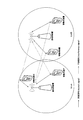
- FIG. 7 is a diagram illustrating an interference signal to a neighboring cell according to the prior art.
- mobile station apparatus 1A and mobile station apparatus 1B transmit signals to base station apparatus 3A, and signals from mobile station apparatus 1A and signals from mobile station apparatus 1B are spatially multiplexed.
- mobile station apparatus 1C and mobile station apparatus 1D transmit signals to base station apparatus 3B. At this time, both the signal of the mobile station apparatus 1A and the signal of the mobile station apparatus 1B become interference to the cell B, and both the signal of the mobile station apparatus 1C and the signal of the mobile station apparatus 1D become interference to the cell A.
- Non-Patent Document 1 describes a technique for reducing the power of a signal transmitted by a mobile station apparatus in accordance with the number of mobile station apparatuses scheduled at the same frequency in order to suppress interference with adjacent cells.
- the mobile station apparatus calculates transmission power from Equation (3) in Non-Patent Document 1.
- the base station apparatus needs to notify the mobile station apparatus of the number of mobile station apparatuses scheduled to the same frequency, and the overhead of signals from the base station apparatus to the mobile station apparatus increases. There was a problem.
- the present invention has been made in view of the above points, and its purpose is to suppress signal overhead from the base station apparatus to the mobile station apparatus in a wireless communication system in which the mobile station apparatus and the base station apparatus communicate with each other. It is another object of the present invention to provide a radio communication system, a base station apparatus, a mobile station apparatus, a radio communication method, and an integrated circuit that can efficiently control the power of a signal from the mobile station apparatus to the base station apparatus.
- the mobile station apparatus of the present invention is a mobile station apparatus that communicates with a base station apparatus, includes first transmission power control information and second transmission power control information, and is used for scheduling a physical uplink shared channel.
- the downlink control information to be used is received from the base station apparatus, the value indicated by the first transmission power control information is accumulated, and the accumulated value and the value indicated by the second transmission power control information are obtained. And the transmission power of the physical uplink shared channel is calculated.
- the mobile station apparatus of the present invention is a mobile station apparatus that communicates with a base station apparatus, and includes one transport block according to downlink control information for two transport blocks received from the base station apparatus. Transmission power control mapped to a field to which information indicating the initial transmission or retransmission of the invalid transport block is mapped. The transmission power of the physical uplink shared channel is calculated using the power offset indicated by the information.
- the present invention is characterized in that, in the above mobile station apparatus, the power offset is set to 0 when downlink control information for one transport block is received from the base station apparatus. Yes.
- the base station apparatus of this invention is a base station apparatus which communicates with a mobile station apparatus, Comprising: 1st transmission power control information and 2nd transmission power control information are included, A physical uplink shared channel
- the downlink control information used for scheduling is transmitted to the mobile station apparatus, and the value indicated by the first transmission power control information is accumulated by the mobile station apparatus, and the accumulated value and the second
- the value indicated by the transmission power control information is used by the mobile station apparatus to calculate the transmission power of the physical uplink shared channel.
- the base station apparatus of the present invention is a base station apparatus that communicates with a mobile station apparatus, and one transport block is invalidated in the mobile station apparatus by downlink control information for two transport blocks.
- transmission power control information indicating a power offset is mapped to a field to which information indicating initial transmission or retransmission of the invalid transport block is mapped. It is characterized by doing.
- wireless communications system of this invention is a radio
- the said base station apparatus is 1st transmission power control information and 2nd transmission power.
- Control information and downlink control information used for scheduling of the physical uplink shared channel is transmitted to the mobile station device, and the mobile station device receives the downlink control information control information from the base station device.
- the value indicated by the first transmission power control information is accumulated, and the transmission power of the physical uplink shared channel is calculated using the accumulated value and the value indicated by the second transmission power control information. It is characterized by that.
- the radio communication system of the present invention is a radio communication system in which a base station apparatus and a mobile station apparatus communicate with each other, and the base station apparatus uses the downlink control information for two transport blocks to When the mobile station apparatus indicates that one transport block is invalid and another transport block is valid, information indicating initial transmission or retransmission of the invalid transport block is mapped to a field to be mapped.
- Map transmission power control information indicating a power offset, transmit the downlink control information to the mobile station device, and when the mobile station device receives the downlink control information from the base station device, Using the power offset indicated by the transmission power control information, calculating the transmission power of the physical uplink shared channel It is characterized.
- the present invention provides the wireless communication system described above, wherein the mobile station apparatus indicates the validity of two transport blocks based on downlink control information for the two transport blocks received from the base station apparatus. If it is, the power offset is set to 0.
- the power offset is set to 0. It is characterized by setting.
- the radio communication method of the present invention is a radio communication method used for a mobile station apparatus communicating with a base station apparatus, and includes first transmission power control information and second transmission power control information. , Receiving downlink control information used for scheduling of a physical uplink shared channel from the base station apparatus, accumulating a value indicated by the first transmission power control information, and calculating the accumulated value and the second The transmission power of the physical uplink shared channel is calculated using the value indicated by the transmission power control information.
- a radio communication method of the present invention is a radio communication method used for a mobile station apparatus communicating with a base station apparatus, and downlink control information for two transport blocks received from the base station apparatus. Indicates that one transport block is invalid and another transport block is valid, the information indicating the initial transmission or retransmission of the invalid transport block is mapped to a field to be mapped. The transmission power of the physical uplink shared channel is calculated using a power offset indicated by mapped transmission power control information.
- the present invention is characterized in that the power offset is set to 0 when downlink control information for one transport block is received from the base station apparatus. Yes.
- the radio communication method of the present invention is a radio communication method used for a base station apparatus communicating with a mobile station apparatus, and includes first transmission power control information and second transmission power control information. , Downlink control information used for scheduling of the physical uplink shared channel is transmitted to the mobile station apparatus, and the value indicated by the first transmission power control information is accumulated by the mobile station apparatus and the accumulated And the value indicated by the second transmission power control information are used by the mobile station apparatus to calculate the transmission power of the physical uplink shared channel.
- the radio communication method of the present invention is a radio communication method used for a base station apparatus communicating with a mobile station apparatus, and 1 is assigned to the mobile station apparatus according to downlink control information for two transport blocks.
- a power offset is indicated in the field to which information indicating the initial transmission or retransmission of the invalid transport block is mapped.
- the transmission power control information is mapped.
- An integrated circuit of the present invention is an integrated circuit used in a mobile station apparatus that communicates with a base station apparatus, and includes first transmission power control information and second transmission power control information. Controls processing of the mobile station apparatus that receives downlink control information used for scheduling of an uplink shared channel from the base station apparatus, accumulates a value indicated by the first transmission power control information, and accumulates the accumulation The transmission power of the physical uplink shared channel is calculated using the calculated value and the value indicated by the second transmission power control information.
- An integrated circuit according to the present invention is an integrated circuit used in a mobile station apparatus that communicates with a base station apparatus, and is 1 based on downlink control information for two transport blocks received from the base station apparatus. If the invalidity of one transport block is indicated and the validity of another transport block is indicated, the information indicating the initial transmission or retransmission of the invalid transport block is mapped to the mapped field. The transmission power of the physical uplink shared channel is calculated using the power offset indicated by the transmission power control information.
- the present invention is characterized in that, in the above integrated circuit, the power offset is set to 0 when downlink control information for one transport block is received from the base station apparatus. .
- An integrated circuit of the present invention is an integrated circuit used in a base station apparatus that communicates with a mobile station apparatus, and includes first transmission power control information and second transmission power control information, Controls processing of the base station apparatus that transmits downlink control information used for scheduling of the uplink shared channel to the mobile station apparatus, and the value indicated by the first transmission power control information is accumulated by the mobile station apparatus. The calculated and accumulated value and the value indicated by the second transmission power control information are used by the mobile station apparatus to calculate the transmission power of the physical uplink shared channel.
- An integrated circuit according to the present invention is an integrated circuit used in a base station apparatus that communicates with a mobile station apparatus, and includes one transformer in the mobile station apparatus based on downlink control information for two transport blocks.
- the transmission power indicating the power offset is mapped to the field to which the information indicating the initial transmission or retransmission of the invalid transport block is mapped. It is characterized by mapping control information.
- the present invention in a radio communication system in which a mobile station apparatus and a base station apparatus communicate, it is possible to efficiently control signal power from the mobile station apparatus to the base station apparatus.
- FIG. 1 is a conceptual diagram of a wireless communication system according to an embodiment of the present invention. It is a table
- FIG. 1 is a conceptual diagram of a wireless communication system according to an embodiment of the present invention.
- the radio communication system includes mobile station apparatuses 1 A to 1 C and a base station apparatus 3.
- FIG. 1 shows a synchronization signal (Synchronization signal: SS), downlink reference signal (Downlink Signal: DL RS), physical broadcast channel in wireless communication (downlink) from the base station device 3 to the mobile station devices 1A to 1C.
- Physical Broadcast Channel PBCH
- Physical downlink control channel Physical Downlink ⁇ Control Channel: PDCCH
- Physical downlink shared channel Physical Downlink Shared Channel: PDSCH
- Physical multicast channel Physical Multicast Channel: PMCH
- Physical control format It indicates that an indicator channel (Physical Format Indicator Channel: PCFICH) and a physical HARQ indicator channel (Physical Hybrid ARQ ⁇ Indicator Channel: PHICH) are used.
- FIG. 1 shows an uplink reference signal (Uplink Reference Signal: UL ⁇ ⁇ RS), physical uplink control channel (Physical Uplink Control Channel) in wireless communication (uplink) from the mobile station devices 1A to 1C to the base station device 3. : PUCCH), physical uplink shared channel (Physical Uplink Shared Channel: PUSCH), physical random access channel (Physical Random Access Channel: PRACH).
- the mobile station apparatuses 1A to 1C are referred to as the mobile station apparatus 1.
- the synchronization signal is a signal used for the mobile station apparatus 1 to synchronize the downlink frequency domain and time domain.
- the downlink reference signal is used by the mobile station apparatus 1 to synchronize the downlink frequency domain and time domain, the mobile station apparatus 1 is used to measure downlink reception quality, or the mobile station This is a signal used by the device 1 to perform PDSCH or PDCCH propagation path correction.
- PBCH is a physical channel used to broadcast system information (Broadcast Channel: BCH). System information transmitted on the PBCH is referred to as Master Information Block (MIB).
- MIB Master Information Block
- the PDCCH is a physical channel used for transmitting downlink control information (Downlink Control Information: DCI) such as downlink assignment (also referred to as downlink assignment or downlink grant) and uplink grant (uplink grant).
- DCI Downlink Control Information
- the downlink assignment includes information on modulation scheme and coding rate for PDSCH (Modulation & Coding Scheme: MCS), information indicating radio resource allocation, and the like.
- MCS Modulation & Coding Scheme
- the uplink grant is composed of information on the modulation scheme and coding rate for PUSCH, information indicating radio resource allocation, and the like. A detailed configuration of the uplink grant will be described later.
- PDSCH is a physical channel used to transmit paging information (Paging Channel: PCH), system information different from system information transmitted by PBCH, and downlink data (Downlink Shared Channel: DL-SCH).
- System information transmitted on the PDSCH is referred to as System Information Block (SIB).
- the PMCH is a physical channel used for transmitting information (Multicast Channel: MCH) related to MBMS (Multimedia Broadcast and Multicast Service).
- MCH Multicast Channel
- MCH Multimedia Broadcast and Multicast Service
- PCFICH is a physical channel used for transmitting information indicating an area where a PDCCH is arranged.
- the PHICH is a physical channel used for transmitting a HARQ indicator (response information) indicating success or failure of decoding of the uplink data received by the base station apparatus 3.
- the HARQ indicator for the uplink data indicates ACK (ACKnowledgement), and the base station apparatus 3 decodes the uplink data included in the PUSCH.
- the HARQ indicator for the uplink data indicates NACK (Negative ACKnowledgement).
- a single PHICH transmits a HARQ indicator for a single uplink data.
- HARQ indicators for a plurality of uplink data included in the same PUSCH are transmitted using a plurality of PHICHs.
- the uplink reference signal is used for the base station device 3 to synchronize the uplink time domain, the base station device 3 is used to measure uplink reception quality, or the base station device 3 It is a signal used to perform propagation channel correction for PUSCH and PUCCH.
- Uplink reference signals include DMRS (Demodulation Reference Signal) transmitted time-multiplexed with PUSCH or PUCCH, and SRS (Sounding Reference Signal) transmitted regardless of PUSCH and PUCCH.
- the PUCCH is channel state information (Channel State: CSI) indicating downlink channel quality, a scheduling request (Scheduling Request: SR) indicating a request for radio resources of the PUSCH, and decoding of downlink data received by the mobile station apparatus 1.
- CSI Channel State
- SR scheduling request
- This is a physical channel used for transmitting uplink control information (Uplink Control Information: UCI), which is information used for communication control, such as ACK / NACK indicating success or failure of.
- UCI Uplink Control Information
- the PUSCH is a physical channel used for transmitting uplink data and uplink control information.
- PRACH is a physical channel used for transmitting a random access preamble.
- the PRACH is mainly used for the mobile station apparatus 1 to synchronize with the base station apparatus 3 in the time domain, and is also used for initial access, handover, reconnection request, and uplink radio resource allocation request. It is done.
- Uplink data (UL-SCH) and downlink data (DL-SCH) are transport channels.
- a unit for transmitting uplink data by PUSCH and a unit for transmitting downlink data by PDSCH are referred to as transport blocks (transport TB).
- the transport block is a unit handled in a MAC (Media Access Control) layer, and HARQ (retransmission) control is performed for each transport block.
- a unit of data handled in the MAC layer such as uplink data (UL-SCH) and downlink data (DL-SCH) is also referred to as MAC PDU (Protocol Data Unit).
- MAC PDU Protocol Data Unit
- transport blocks are mapped to code words, and encoding processing is performed for each code word.
- cell aggregation carrier aggregation
- a plurality of serving cells are aggregated.
- One serving cell among a plurality of aggregated serving cells is a primary cell (PrimaryPrimcell: Pcell).
- the primary cell is a serving cell having the same function as the LTE cell.
- the serving cell excluding the primary cell is a secondary cell (SecondScell).
- the secondary cell is a cell whose function is more limited than that of the primary cell, and is mainly used for transmission / reception of PDSCH and / or PUSCH.
- the mobile station apparatus 1 transmits PUCCH only in the primary cell.
- the mobile station device 1 does not receive paging and system information transmitted on the PBCH and PDSCH of the secondary cell.
- the carrier corresponding to the serving cell in the downlink is a downlink component carrier (Downlink Component Carrier: DL CC), and the carrier corresponding to the serving cell in the uplink is an uplink component carrier (Uplink Component Carrier: UL CCC).
- the carrier corresponding to the primary cell in the downlink is a downlink primary component carrier (Downlink Primary Component Carrier: DL PCC), and the carrier corresponding to the primary cell in the uplink is an uplink primary component carrier (Uplink Primary Component Carrier: UL PCC). ).
- the carrier corresponding to the secondary cell in the downlink is a downlink secondary component carrier (Downlink Secondary Component Carrier: DL SCC), and the carrier corresponding to the secondary cell in the uplink is an uplink secondary component carrier (Uplink Secondary Component Carrier: UL SCC). ).
- Downlink Secondary Component Carrier Downlink Secondary Component Carrier: DL SCC
- Uplink Secondary Component Carrier Uplink Secondary Component Carrier: UL SCC
- the physical channel transmitted in the serving cell has the same channel structure as LTE. Each physical channel is transmitted in any one serving cell. That is, a single physical channel is not transmitted in multiple serving cells.
- One PDSCH can be transmitted in one serving cell (DL CC), and one serving cell (UL CC) At most, one PUSCH can be transmitted.
- the downlink assignment used for the scheduling of the PDSCH of the primary cell and the uplink grant used for the scheduling of the PUSCH of the primary cell are transmitted on the PDCCH of the primary cell.
- One serving cell in which the downlink assignment used for PDSCH scheduling of the secondary cell and the uplink grant used for scheduling of the PUSCH of the secondary cell are transmitted by PDCCH is set by the base station apparatus 3 for each secondary cell.
- the base station device 3 sets, for each serving cell, whether or not the downlink assignment and the uplink grant include a carrier indicator (Carrier Indicator) that is information indicating the serving cell corresponding to the downlink assignment and the uplink grant.
- a carrier indicator Carrier Indicator
- the PHICH is transmitted in the serving cell to which the uplink grant used for scheduling of PUSCH to which the PHICH corresponds is transmitted.
- the format of the downlink control information is called a DCI format (DCIDformat).
- the DCI format of uplink grant is DCI format 0 used for scheduling of PUSCH in a single cell in single antenna port mode, and DCI format used for scheduling of PUSCH in a single cell in multi-antenna port mode. 4 is prepared.
- the mobile station apparatus 1 monitors DCI format 0 and DCI format 4 simultaneously.
- the mobile station apparatus 1 transmits PUSCH in the single antenna port mode when detecting DCI format 0, and transmits PUSCH in multi-antenna port mode when detecting DCI format 4.
- the mobile station apparatus 1 transmits a single transport block to the base station apparatus 3 using a single PUSCH in the single antenna port mode.
- the mobile station apparatus 1 transmits up to two transport blocks to the base station apparatus 3 using a single PUSCH in the multi-antenna port mode.
- the mobile station apparatus 1 transmits PUSCH using MIMO SM (Multiple Input Multiple Output Spatial Multiplexing).
- MIMO SM is a technique in which a plurality of signals are multiplexed and transmitted / received on a plurality of spatial dimension channels realized by a plurality of transmission antenna ports and a plurality of reception antenna ports.
- the antenna port indicates a logical antenna used for signal processing, and one antenna port may be configured by one physical antenna or may be configured by a plurality of physical antennas. Also good.
- a process for forming an appropriate spatial channel (referred to as precoding) is performed for a plurality of signals, and the plurality of signals subjected to the precoding process are processed. Are transmitted using a plurality of transmission antennas.
- processing for appropriately separating signals multiplexed on a spatial dimension channel from a plurality of signals received using a plurality of receiving antennas is performed.
- a plurality of fields are defined in DCI format 4, and information bits are mapped to each of the plurality of fields.
- the fields defined in DCI format 4 are listed below. Note that fields other than those listed below may be defined in the DCI format 4.
- Modulation and coding scheme and redundancy version for first transport block field A field to which an information bit indicating initial transmission or retransmission of uplink data for the first transport block is mapped (New data indicator for first transport block field) —1 bit -Modulation and coding scheme and redundancy version for second transport block field-5 bit.
- Modulation and coding scheme and redundancy version for second transport block field A field to which an information bit indicating initial transmission or retransmission of uplink data for the second transport block is mapped (New data indicator for second transport block field) —1 bit
- the number of bits [x] of the Resource block assignment field is determined according to the uplink bandwidth.
- the number of bits of Precoding information and number of layers field is 3 bits when the number of antenna ports when the mobile station apparatus 1 transmits PUSCH is 2, and the antenna when the mobile station apparatus 1 transmits PUSCH. When the number of ports is 4, it is 6 bits.
- the redundancy version indicates which part of the encoded bit sequence of the transport block the mobile station apparatus 1 transmits on the PUSCH.
- more than one physical resource block (Physical Resource Block: PRB) is indicated by Resource block assignment field, and 0 is set in modulation, and coding, scheme, and redundancy, version, for first, transport, block, and field corresponding to the transport block. Or a combination in which one physical resource block is indicated by Resource block assignment field and 28 is set in Modulation and coding scheme and redundancy version for first transport block field to which the transport block corresponds In either case, the transport block is invalid.
- the mobile station apparatus 1 determines that a transport block that is not invalid is valid.
- the mobile station device 1 does not transmit an invalid transport block (disabled transport block) on the PUSCH, but transmits an effective transport block (enabled transport block) on the PUSCH.
- the physical resource block is a unit for allocating PUSCH, and includes a frequency band (180 kHz) and a time band (0.5 msec) having a predetermined width.
- FIG. 2 is a table showing the correspondence between the New data indicator field and ⁇ power-offset for a transport block which is invalid in the present invention. If the New data indicator field for an invalid transport block is set to 0, ⁇ power-offset is ⁇ 10 log 10 (2). If the New data indicator field for an invalid transport block is set to 1, ⁇ power-offset is 0. If two transport blocks are valid in DCI format 4, or if PUSCH is scheduled in DCI format 0, ⁇ power-offset is zero.
- the base station apparatus 3 adds a cyclic redundancy check (Cyclic Redundancy Check: CRC) code generated from the downlink control information to the downlink control information.
- CRC Cyclic Redundancy Check
- the added cyclic redundancy check code is scrambled with RNTI (Radio Network Temporary Identifier).
- RNTI Radio Network Temporary Identifier
- the mobile station apparatus 1 when the mobile station apparatus 1 has its cyclic redundancy check code scrambled by C-RNTI (Cell-Radio Network Temporary Identity) assigned from the base station apparatus 3, the mobile station apparatus 1 stores the downlink control information in its own apparatus. If it is determined that the radio resource is addressed and the cyclic redundancy check code is scrambled by the SPS (Semi-Persistent-Scheduling) C-RNTI allocated from the base station apparatus 3, the downlink control information is It is determined that this indicates an allocation of a permanent (periodic) radio resource addressed to the own apparatus, a release of a permanent radio resource, or a retransmission of a PUSCH transmitted using the permanent radio resource.
- C-RNTI Cell-Radio Network Temporary Identity
- the fact that the cyclic redundancy check code scrambled by the RNTI is added to the downlink control information is simply expressed as the RNTI is included in the downlink control information or the RNTI is included in the PDCCH.
- the mobile station apparatus 1 decodes the PDCCH and the cyclic redundancy check code added to the downlink control information matches the cyclic redundancy check code generated from the downlink control information received by the mobile station apparatus 1 It is determined that the acquisition of the PDCCH is successful, and if the PDCCH is not matched, it is determined that the decoding of the PDCCH has failed. This process is called blind decoding or monitoring.
- the mobile station apparatus 1 sets the transmission power for the PUSCH based on the equation (1) or (2).
- the mobile station apparatus 1 sets the transmission power P PUSCH, c (i) for the PUSCH of the subframe i in the serving cell c. (1) Perform based on the equation.
- Mobile station apparatus 1 in the case of simultaneously transmitting the PUCCH and PUSCH in the subframe i of the serving cell c is the transmission power P PUSCH for the PUSCH subframe i of the serving cell c, setting the (2) equation of c (i) Based on.
- P CMAX, c is the maximum transmission power value set in subframe i of serving cell c
- P ′ CMAX, c is the true number of P CMAX, c
- P 'PUCCH, c is the antilog of the transmission power of the PUCCH to be transmitted in subframe i of the serving cell c.
- M PUSCH, c (i) is the PUSCH resource allocation bandwidth expressed by the number of physical resource blocks in subframe i of serving cell c.
- P O_PUSCH, c is a parameter designated from the upper layer for the serving cell c
- ⁇ c is a 3-bit parameter designated from the upper layer for the serving cell c
- ⁇ 0, 0.4, One of 0.5, 0.6, 0.7, 0.8, 0.9, 1 ⁇ is designated.
- PL c is a downlink path loss for the serving cell c measured by the mobile station device 1. The downlink path loss for the serving cell c may be measured from the primary cell.
- ⁇ TF, c (i) is an offset calculated from the resource amount and the transport block size at the time of initial transmission for the PUSCH transmitted in subframe i of serving cell c.
- f c (i) is a value calculated from a TPC command included in DCI format 0 or DCI format 4 for serving cell c.
- Mobile station apparatus 1 depending on the message of the upper layer received from the base station device 3, as a mode of calculating the f c (i), sets the first mode (accumulation mode) or the second mode (absolute) .
- Mobile station apparatus 1 that sets the first mode, the initial value of f c ( ⁇ ) and f c (0) 0, accumulating the value of the TPC command for the serving cell c to f c ( ⁇ ) .
- the mobile station apparatus 1 that has set the second mode sets the value of the TPC command for the subframe i of the serving cell c as f c (i).
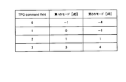
- TPC command 3 is a table showing the correspondence between TPC commands and power values according to the present invention.
- the correspondence between the TPC command and the value is different between the first mode and the second mode.
- the TPC command indicates one value of ⁇ -1, 0, 1, 3 ⁇ .
- the TPC command indicates one value of ⁇ -4, -1, 1, 4 ⁇ .
- ⁇ power-offset (i) is a value that is explicitly or implicitly indicated by DCI format 0 or DCI format 4 for the serving cell c. If the New data indicator field for an invalid transport block is set to 0, ⁇ power-offset is ⁇ 10 log 10 (2). If the New data indicator field for an invalid transport block is set to 1, ⁇ power-offset is 0. If two transport blocks are valid in DCI format 4, or if PUSCH is scheduled in DCI format 0, ⁇ power-offset is zero. When the mobile station apparatus 1 does not receive the DCI format 0 and the DCI format 4 in the subframe i and receives a NACK in PHICH for the transport block, the mobile station apparatus 1 receives the DCI format 0 last received for the transport block. Alternatively , the value of ⁇ power-offset is determined according to DCI format 4.
- the mobile station apparatus 1 transmits a power headroom (PH) for each serving cell to the base station apparatus 3.
- PH power headroom
- the mobile station apparatus 1 sets the power headroom PH type1, c (i) for the PUSCH of the subframe i of the serving cell c to ( 3) Calculate from the equation.
- the mobile station apparatus 1 calculates the power headroom PH type1, c (i) for the PUSCH of the subframe i of the serving cell c from Equation (4). To do.
- P ′′ CMAX, c is the maximum transmission power value set not to take backoff in subframe i of serving cell c.
- FIG. 4 is a schematic block diagram showing the configuration of the base station apparatus 3 of the present invention.
- the base station apparatus 3 includes an upper layer processing unit 301, a control unit 303, a reception unit 305, a transmission unit 307, and a transmission / reception antenna 309.
- the upper layer processing unit 301 includes a radio resource control unit 3011, a scheduling unit 3013, and a control information generation unit 3015.
- the reception unit 305 includes a decoding unit 3051, a demodulation unit 3053, a demultiplexing unit 3055, a wireless reception unit 3057, and a channel measurement unit 3059.
- the transmission unit 307 includes an encoding unit 3071, a modulation unit 3073, a multiplexing unit 3075, a radio transmission unit 3077, and a downlink reference signal generation unit 3079.
- the upper layer processing unit 301 includes a medium access control (MAC: Medium Access Control) layer, a packet data integration protocol (Packet Data Convergence Protocol: PDCP) layer, a radio link control (Radio Link Control: RLC) layer, a radio resource control (Radio). Resource (Control: RRC) layer processing.
- MAC Medium Access Control
- PDCP Packet Data Convergence Protocol
- RLC Radio Link Control
- Radio Radio Resource Control
- Control Control: RRC
- the radio resource control unit 3011 provided in the upper layer processing unit 301 generates downlink data (transport block), RRC signal, MAC CE (Control Element) arranged in the downlink PDSCH, or acquires it from the upper node. And output to the transmission unit 307. Further, the radio resource control unit 3011 manages various setting information of each mobile station apparatus 1. For example, the radio resource control unit 3011 performs management of the mode of the TPC command, management of the serving cell set in the mobile station apparatus 1 and the like.
- the scheduling unit 3013 included in the higher layer processing unit 301 performs PDSCH and PUSCH scheduling, and notifies the control information generation unit 3015 of the scheduling result.
- Scheduling section 3013 determines a pair of mobile station apparatuses 1 that perform MU-MIMO, and notifies downlink control information generation section 3015 of the pair of mobile station apparatuses 1 that perform MU-MIMO.
- the scheduling unit 3013 determines a parameter related to uplink transmission power, and notifies the determined parameter to the control information generation unit 3015.
- a control information generation unit 3015 included in the higher layer processing unit 301 generates downlink control information transmitted on the PDCCH based on the scheduling result notified from the scheduling unit 3013.
- the control information generation unit 3015 has a DCI format indicating that one transport block is invalid and ⁇ power-offset is ⁇ 10 log 10 (2) for the mobile station apparatus 1 performing MU-MIMO notified from the scheduling unit 3013. 4 is generated.
- the control information generation unit 3015 generates information indicating the parameter based on the parameter regarding the uplink transmission power notified from the scheduling unit 3013.
- the control unit 303 generates a control signal for controlling the reception unit 305 and the transmission unit 307 based on the control information from the higher layer processing unit 301.
- the control unit 303 outputs the generated control signal to the reception unit 305 and the transmission unit 307 and controls the reception unit 305 and the transmission unit 307.
- the reception unit 305 separates, demodulates, decodes, and decodes the PUCCH, PUSCH, PRACH, and uplink reference signal received from the mobile station apparatus 1 via the transmission / reception antenna 309 according to the control signal input from the control unit 303 The information is output to the upper layer processing unit 301.
- the receiving unit 305 measures the state of the uplink channel from the received uplink signal and outputs the measurement result to the higher layer processing unit 301.
- the transmission unit 307 generates a downlink reference signal according to the control signal input from the control unit 303, encodes and modulates the HARQ indicator, downlink control information, and downlink data input from the higher layer processing unit 301. Then, the PHICH, PDCCH, PDSCH, and downlink reference signal are multiplexed, and the signal is transmitted to the mobile station device 1 via the transmission / reception antenna 309.
- FIG. 5 is a schematic block diagram showing the configuration of the mobile station apparatus 1 of the present invention.
- the mobile station apparatus 1 includes an upper layer processing unit 101, a control unit 103, a receiving unit 105, a transmitting unit 107, and a transmission / reception antenna 109.
- the upper layer processing unit 101 includes a radio resource control unit 1011, a scheduling unit 1013, and a transmission power control unit 1015.
- the reception unit 105 includes a decoding unit 1051, a demodulation unit 1053, a demultiplexing unit 1055, a radio reception unit 1057, and a channel measurement unit 1059.
- the transmission unit 107 includes an encoding unit 1071, a modulation unit 1073, a multiplexing unit 1075, a radio transmission unit 1077, and an uplink reference signal generation unit 1079.
- the upper layer processing unit 101 outputs uplink data generated by a user operation or the like to the transmission unit 107.
- the upper layer processing unit 101 includes a medium access control (MAC: Medium Access Control) layer, a packet data integration protocol (Packet Data Convergence Protocol: PDCP) layer, a radio link control (Radio Link Control: RLC) layer, and radio resource control. Process the (Radio Resource Control: RRC) layer.
- MAC Medium Access Control
- PDCP Packet Data Convergence Protocol
- RLC Radio Link Control
- RRC Radio Resource Control
- upper layer processing section 101 generates control information for controlling receiving section 105 and transmitting section 107 and outputs the control information to control section 103. *
- the radio resource control unit 1011 included in the upper layer processing unit 101 manages various setting information of the own device. For example, the radio resource control unit 1011 manages the TPC command mode and the serving cell. The radio resource control unit 1011 generates information arranged in each uplink channel and outputs the information to the transmission unit 107.
- the scheduling unit 1013 included in the higher layer processing unit 101 controls the receiving unit 105 via the control unit 103 so as to receive the PDSCH according to the downlink assignment input from the receiving unit 105.
- the scheduling unit 1013 controls the transmission unit 107 via the control unit 103 so as to transmit the PUSCH according to the uplink grant input from the reception unit 105.
- the scheduling unit 1013 outputs the TPC command included in the uplink grant to the transmission power control unit 1015.
- the scheduling unit 1013 confirms that ⁇ power-offset is 0 when the last received DCI format for the PUSCH is DCI format 0 or DCI format 4 in which two transport blocks are valid.
- the transmission power control unit 1015 is notified.
- the scheduling unit 1013 uses the value set in the New data indicator field for the invalid transport block.
- the transmission power control unit 1015 is notified of the determined ⁇ power-offset .
- the control unit 103 generates a control signal for controlling the receiving unit 105 and the transmitting unit 107 based on the control information from the higher layer processing unit 101. Control unit 103 outputs the generated control signal to receiving unit 105 and transmitting unit 107 to control receiving unit 105 and transmitting unit 107.
- the receiving unit 105 separates, demodulates, decodes, and decodes the PHICH, PDCCH, PDSCH, and downlink reference signal received from the base station apparatus 3 via the transmission / reception antenna 109 according to the control signal input from the control unit 103.
- the information is output to the upper layer processing unit 101.
- the receiving unit 105 measures the state of the uplink channel from the received downlink signal, and outputs the measurement result to the higher layer processing unit 101.
- the transmission unit 107 generates an uplink reference signal according to the control signal input from the control unit 103, encodes and modulates the uplink data (transport block) input from the higher layer processing unit 101, PUCCH, The PUSCH and the generated uplink reference signal are multiplexed and transmitted to the base station apparatus 3 via the transmission / reception antenna 109.
- FIG. 6 is a flowchart showing an example of the operation of the mobile station apparatus 1 of the present invention.
- the mobile station apparatus 1 sets the upper layer parameter regarding the transmission power control received from the base station apparatus 3 (step S100).
- the mobile station apparatus 1 receives the upper layer signal indicating the TPC command mode from the base station apparatus 3, and sets the TPC command mode according to the received upper layer signal (step S102).
- the mobile station apparatus 1 sets the TPC command mode to the default mode.
- the default mode is a predetermined mode and may be the first mode or the second mode.
- the mobile station apparatus 1 receives the uplink grant (DCI format 0 or DCI format 4) used for PUSCH scheduling (step S102).
- the mobile station apparatus 1 is invalid if the last received uplink grant is DCI format 4 (step S103-DCI format 4) and one transport block is invalid (step S104-Yes).
- ⁇ power-offset is determined from the value set in the New data indicator field for the transport block (step S105).
- Step S105-0 When 0 is set in the New data indicator field in Step S105 (Step S105-0), the mobile station apparatus 1 sets ⁇ power-offset to ⁇ 10 log 10 (2) (Step S106). If 1 is set in the New data indicator field in Step S105 (Step S105-1), the mobile station apparatus 1 sets ⁇ power-offset to 0 (Step S107).
- step S103 When the uplink grant last received in step S103 is DCI format 0 (step S103-DCI format 0), the mobile station apparatus 1 sets ⁇ power-offset to 0 (step S107). When the two transport blocks are valid in step S104 (step S104-No), the mobile station device 1 sets ⁇ power-offset to 0 (step S107).
- the mobile station apparatus 1 determines the mode of the TPC command set in step S101 after step S106 or step S107 (step S108).
- the mode of the TPC command is the second mode (absolute) (step S108—second mode)
- the mobile station device 1 sets the value of the TPC command to f c (i). (Step S110).
- the mobile station apparatus 1 calculates the PUSCH transmission power from the equation (1) or (2) after step S109 or step S110 (step S111).
- the base station apparatus 3 uses the TPC command (first transmission power control information) and the ⁇ power-offset. And transmits DCI format 4 (downlink control information) used for scheduling of PUSCH (physical uplink shared channel) to the mobile station apparatus 1.
- DCI format 4 downlink control information
- PUSCH physical uplink shared channel
- 1 receives the DCI format 4 from the base station apparatus 3, accumulates the value indicated by the TPC command (first transmission power control information), and uses the accumulated value and the value of ⁇ power-offset. Then, the transmission power of PUSCH is calculated. Thereby, it is possible to accurately control the transmission power of PUSCH.
- the base station apparatus 3 moves according to the DCI format 4 (downlink control information for two transport blocks).
- DCI format 4 downlink control information for two transport blocks.
- the station apparatus 1 indicates that one transport block is invalid and another transport block is valid, a new data indicator field (information indicating initial transmission or retransmission) of the invalid transport block is displayed.
- the transmission power control information indicating ⁇ power-offset (power offset) is mapped to the mapped field), and the DCI format 4 is transmitted to the mobile station apparatus 1.
- the mobile station apparatus 1 bases the DCI format 4 on the base
- the transmission power of PUSCH is calculated using ⁇ power-offset indicated by the transmission power control information. To do.
- the base station apparatus 3 can re-use the New data indicator field of the invalid transport block and notify the mobile station apparatus 1 of ⁇ power-offset.
- the power of the signal to the station device can be controlled.
- a program that operates in the base station apparatus 3 and the mobile station apparatus 1 related to the present invention is a program (computer functions as a computer) that controls a CPU (Central Processing Unit) so as to realize the functions of the above-described embodiments related to the present invention Program).
- Information handled by these devices is temporarily stored in RAM (Random Access Memory) during the processing, and then stored in various ROMs such as Flash ROM (Read Only Memory) and HDD (Hard Disk Drive). Reading, correction, and writing are performed by the CPU as necessary.
- the program for realizing the control function may be recorded on a computer-readable recording medium, and the program recorded on the recording medium may be read by the computer system and executed.
- the “computer system” here is a computer system built in the mobile station apparatus 1 or the base station apparatus 3, and includes an OS and hardware such as peripheral devices.
- the “computer-readable recording medium” refers to a storage device such as a flexible medium, a magneto-optical disk, a portable medium such as a ROM or a CD-ROM, and a hard disk incorporated in a computer system.
- the “computer-readable recording medium” is a medium that dynamically holds a program for a short time, such as a communication line when transmitting a program via a network such as the Internet or a communication line such as a telephone line,
- a volatile memory inside a computer system serving as a server or a client may be included and a program that holds a program for a certain period of time.
- the program may be a program for realizing a part of the functions described above, and may be a program capable of realizing the functions described above in combination with a program already recorded in a computer system.
- a part or all of the mobile station device 1 and the base station device 3 in the above-described embodiment may be realized as an LSI that is typically an integrated circuit, or may be realized as a chip set.
- Each functional block of the mobile station device 1 and the base station device 3 may be individually chipped, or a part or all of them may be integrated into a chip.
- the method of circuit integration is not limited to LSI, and may be realized by a dedicated circuit or a general-purpose processor.
- an integrated circuit based on the technology can also be used.
Landscapes
- Engineering & Computer Science (AREA)
- Signal Processing (AREA)
- Computer Networks & Wireless Communication (AREA)
- Mobile Radio Communication Systems (AREA)
Abstract
移動局装置と基地局装置とが通信する無線通信システムにおいて、効率的に移動局装置から基地局装置への信号の電力を制御する。スケジューリング部(1013)は、PUSCHに対する最後に受信したDCIフォーマットが、DCIフォーマット0である、または2つのトランスポートブロックが有効であるDCIフォーマット4である場合には、δpower-offsetが0であることを送信電力制御部(1015)に通知する。スケジューリング部(1013)は、PUSCHに対する最後に受信したDCIフォーマットが、1つのトランスポートブロックが無効であるDCIフォーマット4である場合には、無効であるトランスポートブロックに対するNew data indicator fieldにセットされた値から決定されるδpower-offsetを送信電力制御部(1015)に通知する。
Description
本発明は、無線通信システム、基地局装置、移動局装置、無線通信方法および集積回路に関する。
セルラー移動通信の無線アクセス方式および無線ネットワークの進化(以下、「Long Term Evolution (LTE)」、または、「Evolved Universal Terrestrial Radio Access (EUTRA)」と称する。)が、第三世代パートナーシッププロジェクト(3rd Generation Partnership Project: 3GPP)において検討されている。LTEでは、基地局装置から移動局装置への無線通信(下りリンク)の通信方式として、マルチキャリア送信である直交周波数分割多重(Orthogonal Frequency Division Multiplexing: OFDM)方式が用いられる。また、移動局装置から基地局装置への無線通信(上りリンク)の通信方式として、シングルキャリア送信であるSC-FDMA(Single-Carrier Frequency Division Multiple Access)方式が用いられる。LTEでは、基地局装置をenhanced NodeB(eNodeB)、移動局装置をUser Equipment (UE)と称する。
LTEにおいて、基地局装置は、下りリンク制御情報(Downlink Control Information: DCI)を用いて上りリンクデータ(または、「uplink shared channel: UL-SCH」と称する。)送信用のチャネルであるPUSCH(Physical Uplink Shared Channel)の初期送信または再送信を移動局装置に指示する。下りリンク制御情報は、PDCCH(Physical Downlink Control Channel)で送信される。
LTEでは、キャパシティを改善するために、MU-MIMO(Multi User-Multiple Input Multiple Output)が導入されている。MU-MIMOは、複数の移動局装置が同一時刻の、同一周波数で、PUSCHを用いて1つまたは複数のデータ系列を送信し、基地局装置が受信時に移動局装置それぞれが送信した1つまたは複数のデータ系列を分離する技術である。
しかしながら、複数の移動局装置からの複数のデータ系列が同一周波数に空間多重されるため、隣接セルへの干渉が増加してしまう。図7は、従来技術の隣接セルへの干渉信号を示す図である。図7のセルAにおいて、移動局装置1Aと移動局装置1Bとが基地局装置3Aに信号を送信しており、移動局装置1Aの信号と移動局装置1Bの信号が空間多重されている。図7のセルBにおいて、移動局装置1Cと移動局装置1Dとが基地局装置3Bに信号を送信している。このとき、移動局装置1Aの信号と移動局装置1Bの信号両方が、セルBへの干渉となり、移動局装置1Cの信号と移動局装置1Dの信号両方が、セルAへの干渉となる。
非特許文献1には、隣接セルへの干渉を抑えるために、同一周波数にスケジュールされる移動局装置の数に応じて、移動局装置が送信する信号の電力を下げる技術が記載されている。非特許文献1において、移動局装置は非特許文献1の(3)式から送信電力を算出する。
"Investigation on Resource Assignment and Power Control Schemes for Uplink MU-MIMO in Multi-cell Environments for LTE/LTE-Advanced", NTT DOCOMO, INC, 2010 16th Asia-Pacific Conference on Communications (APCC), Issue Date : Oct. 31 2010 - Nov. 3 2010.
しかしながら、従来の技術では、基地局装置が移動局装置に同一周波数にスケジュールされる移動局装置の数を通知する必要があり、基地局装置から移動局装置への信号のオーバーヘッドが増加してしまうという問題があった。
本発明は上記の点に鑑みてなされたものであり、その目的は、移動局装置と基地局装置とが通信する無線通信システムにおいて、基地局装置から移動局装置への信号のオーバーヘッドを抑え、また効率的に移動局装置から基地局装置への信号の電力を制御することができる無線通信システム、基地局装置、移動局装置、無線通信方法および集積回路を提供することを目的とする。
(1)上記の目的を達成するために、本発明は、以下のような手段を講じた。すなわち、本発明の移動局装置は、基地局装置と通信する移動局装置であって、第1の送信電力制御情報と第2の送信電力制御情報とを含み、物理上りリンク共用チャネルのスケジューリングに用いられる下りリンク制御情報を前記基地局装置から受信し、前記第1の送信電力制御情報が示す値を累算し、前記累算された値と前記第2の送信電力制御情報が示す値を用いて、物理上りリンク共用チャネルの送信電力を算出することを特徴としている。
(2)また、本発明の移動局装置は、基地局装置と通信する移動局装置であって、前記基地局装置から受信した、2つのトランスポートブロックに対する下りリンク制御情報によって1つのトランスポートブロックの無効を示され、もう1つのトランスポートブロックの有効を示された場合には、前記無効であるトランスポートブロックの初期送信または再送信を示す情報がマップされるフィールドにマップされる送信電力制御情報が示す電力オフセットを用いて、前記物理上りリンク共用チャネルの送信電力を算出することを特徴としている。
(3)また、本発明は、上記の移動局装置において、前記基地局装置から受信した、2つのトランスポートブロックに対する下りリンク制御情報によって2つのトランスポートブロックの有効を示された場合には、前記電力オフセットを0にセットすることを特徴としている。
(4)また、本発明は、上記の移動局装置において、前記基地局装置から1つのトランスポートブロックに対する下りリンク制御情報を受信した場合には、前記電力オフセットを0にセットすることを特徴としている。
(5)また、本発明の基地局装置は、移動局装置と通信する基地局装置であって、第1の送信電力制御情報と第2の送信電力制御情報とを含み、物理上りリンク共用チャネルのスケジューリングに用いられる下りリンク制御情報を前記移動局装置に送信し、前記第1の送信電力制御情報が示す値は、前記移動局装置によって累算され、前記累算された値と前記第2の送信電力制御情報が示す値は、前記移動局装置によって物理上りリンク共用チャネルの送信電力の算出に用いられることを特徴としている。
(6)また、本発明の基地局装置は、移動局装置と通信する基地局装置であって、2つのトランスポートブロックに対する下りリンク制御情報によって、前記移動局装置に1つのトランスポートブロックの無効を示し、もう1つのトランスポートブロックの有効を示す場合には、前記無効であるトランスポートブロックの初期送信または再送信を示す情報がマップされるフィールドに、電力オフセットを示す送信電力制御情報をマップすることを特徴としている。
(7)また、本発明の無線通信システムは、基地局装置と移動局装置とが通信する無線通信システムであって、前記基地局装置は、第1の送信電力制御情報と第2の送信電力制御情報とを含み、物理上りリンク共用チャネルのスケジューリングに用いられる下りリンク制御情報を前記移動局装置に送信し、前記移動局装置は、前記下りリンク制御情報制御情報を前記基地局装置から受信し、前記第1の送信電力制御情報が示す値を累算し、前記累算された値と前記第2の送信電力制御情報が示す値を用いて、物理上りリンク共用チャネルの送信電力を算出することを特徴としている。
(8)また、本発明の無線通信システムは、基地局装置と移動局装置とが通信する無線通信システムであって、前記基地局装置は、2つのトランスポートブロックに対する下りリンク制御情報によって、前記移動局装置に1つのトランスポートブロックの無効を示し、もう1つのトランスポートブロックの有効を示す場合には、前記無効であるトランスポートブロックの初期送信または再送信を示す情報がマップされるフィールドに、電力オフセットを示す送信電力制御情報をマップし、前記下りリンク制御情報を前記移動局装置に送信し、前記移動局装置は、前記下りリンク制御情報を前記基地局装置から受信した場合には、前記送信電力制御情報が示す電力オフセットを用いて、物理上りリンク共用チャネルの送信電力を算出することを特徴としている。
(9)また、本発明は、上記の無線通信システムにおいて、前記移動局装置が、前記基地局装置から受信した、2つのトランスポートブロックに対する下りリンク制御情報によって2つのトランスポートブロックの有効を示された場合には、前記電力オフセットを0にセットすることを特徴としている。
(10)また、本発明は、上記の無線通信システムにおいて、前記移動局装置が、前記基地局装置から1つのトランスポートブロックに対する下りリンク制御情報を受信した場合には、前記電力オフセットを0にセットすることを特徴としている。
(11)また、本発明の無線通信方法は、基地局装置と通信する移動局装置に用いられる無線通信方法であって、第1の送信電力制御情報と第2の送信電力制御情報とを含み、物理上りリンク共用チャネルのスケジューリングに用いられる下りリンク制御情報を前記基地局装置から受信し、前記第1の送信電力制御情報が示す値を累算し、前記累算された値と前記第2の送信電力制御情報が示す値を用いて、物理上りリンク共用チャネルの送信電力を算出することを特徴としている。
(12)また、本発明の無線通信方法は、基地局装置と通信する移動局装置に用いられる無線通信方法であって、前記基地局装置から受信した、2つのトランスポートブロックに対する下りリンク制御情報によって1つのトランスポートブロックの無効を示され、もう1つのトランスポートブロックの有効を示された場合には、前記無効であるトランスポートブロックの初期送信または再送信を示す情報がマップされるフィールドにマップされる送信電力制御情報が示す電力オフセットを用いて、前記物理上りリンク共用チャネルの送信電力を算出することを特徴としている。
(13)また、本発明は、上記の無線通信方法において、前記基地局装置から受信した、2つのトランスポートブロックに対する下りリンク制御情報によって2つのトランスポートブロックの有効を示された場合には、前記電力オフセットを0にセットすることを特徴としている。
(14)また、本発明は、上記の無線通信方法において、前記基地局装置から1つのトランスポートブロックに対する下りリンク制御情報を受信した場合には、前記電力オフセットを0にセットすることを特徴としている。
(15)また、本発明の無線通信方法は、移動局装置と通信する基地局装置に用いられる無線通信方法であって、第1の送信電力制御情報と第2の送信電力制御情報とを含み、物理上りリンク共用チャネルのスケジューリングに用いられる下りリンク制御情報を前記移動局装置に送信し、前記第1の送信電力制御情報が示す値は、前記移動局装置によって累算され、前記累算された値と前記第2の送信電力制御情報が示す値は、前記移動局装置によって物理上りリンク共用チャネルの送信電力の算出に用いられることを特徴としている。
(16)また、本発明の無線通信方法は、移動局装置と通信する基地局装置に用いられる無線通信方法であって、2つのトランスポートブロックに対する下りリンク制御情報によって、前記移動局装置に1つのトランスポートブロックの無効を示し、もう1つのトランスポートブロックの有効を示す場合には、前記無効であるトランスポートブロックの初期送信または再送信を示す情報がマップされるフィールドに、電力オフセットを示す送信電力制御情報をマップすることを特徴としている。
(17)また、本発明の集積回路は、基地局装置と通信する移動局装置に用いられる集積回路であって、第1の送信電力制御情報と第2の送信電力制御情報とを含み、物理上りリンク共用チャネルのスケジューリングに用いられる下りリンク制御情報を前記基地局装置から受信する前記移動局装置の処理を制御し、前記第1の送信電力制御情報が示す値を累算し、前記累算された値と前記第2の送信電力制御情報が示す値を用いて、物理上りリンク共用チャネルの送信電力を算出することを特徴としている。
(18)また、本発明の集積回路は、基地局装置と通信する移動局装置に用いられる集積回路であって、前記基地局装置から受信した、2つのトランスポートブロックに対する下りリンク制御情報によって1つのトランスポートブロックの無効を示され、もう1つのトランスポートブロックの有効を示された場合には、前記無効であるトランスポートブロックの初期送信または再送信を示す情報がマップされるフィールドにマップされる送信電力制御情報が示す電力オフセットを用いて、前記物理上りリンク共用チャネルの送信電力を算出することを特徴としている。
(19)また、本発明は、上記の集積回路において、前記基地局装置から受信した、2つのトランスポートブロックに対する下りリンク制御情報によって2つのトランスポートブロックの有効を示された場合には、前記電力オフセットを0にセットすることを特徴としている。
(20)また、本発明は、上記の集積回路において、前記基地局装置から1つのトランスポートブロックに対する下りリンク制御情報を受信した場合には、前記電力オフセットを0にセットすることを特徴としている。
(21)また、本発明の集積回路は、移動局装置と通信する基地局装置に用いられる集積回路であって、第1の送信電力制御情報と第2の送信電力制御情報とを含み、物理上りリンク共用チャネルのスケジューリングに用いられる下りリンク制御情報を前記移動局装置に送信する前記基地局装置の処理を制御し、前記第1の送信電力制御情報が示す値は、前記移動局装置によって累算され、前記累算された値と前記第2の送信電力制御情報が示す値は、前記移動局装置によって物理上りリンク共用チャネルの送信電力の算出に用いられることを特徴としている。
(22)また、本発明の集積回路は、移動局装置と通信する基地局装置に用いられる集積回路であって、2つのトランスポートブロックに対する下りリンク制御情報によって、前記移動局装置に1つのトランスポートブロックの無効を示し、もう1つのトランスポートブロックの有効を示す場合には、前記無効であるトランスポートブロックの初期送信または再送信を示す情報がマップされるフィールドに、電力オフセットを示す送信電力制御情報をマップすることを特徴としている。
この発明によれば、移動局装置と基地局装置とが通信する無線通信システムにおいて、効率的に移動局装置から基地局装置への信号の電力を制御することができる。
(第1の実施形態)
以下、図面を参照しながら本発明の第1の実施形態について詳しく説明する。
以下、図面を参照しながら本発明の第1の実施形態について詳しく説明する。
まず、本発明の物理チャネルについて説明する。
図1は、本発明の実施形態に係る無線通信システムの概念図である。図1において、無線通信システムは、移動局装置1A~1C、および基地局装置3を具備する。図1は、基地局装置3から移動局装置1A~1Cへの無線通信(下りリンク)では、同期信号(Synchronization signal: SS)、下りリンク参照信号(Downlink Reference Signal: DL RS)、物理報知チャネル(Physical Broadcast Channel: PBCH)、物理下りリンク制御チャネル(Physical Downlink Control Channel: PDCCH)、物理下りリンク共用チャネル(Physical Downlink Shared Channel: PDSCH)、物理マルチキャストチャネル(Physical Multicast Channel: PMCH)、物理制御フォーマットインディケータチャネル(Physical Control Format Indicator Channel: PCFICH)、物理HARQインディケータチャネル(Physical Hybrid ARQ Indicator Channel: PHICH)が用いられることを示す。
また、図1は、移動局装置1A~1Cから基地局装置3への無線通信(上りリンク)では、上りリンク参照信号(Uplink Reference Signal: UL RS)、物理上りリンク制御チャネル(Physical Uplink Control Channel: PUCCH)、物理上りリンク共用チャネル(Physical Uplink Shared Channel: PUSCH)、物理ランダムアクセスチャネル(Physical Random Access Channel: PRACH)が用いられることを示す。以下、移動局装置1A~1Cを移動局装置1という。
同期信号は、移動局装置1が下りリンクの周波数領域および時間領域の同期をとるために用いられる信号である。下りリンク参照信号は、移動局装置1が下りリンクの周波数領域および時間領域の同期をとるために用いられたり、移動局装置1が下りリンクの受信品質を測定するために用いられたり、移動局装置1がPDSCHやPDCCHの伝搬路補正を行なうために用いられる信号である。PBCHは、システム情報(Broadcast Channel: BCH)を報知するために用いられる物理チャネルである。PBCHで送信されるシステム情報を、MasterInformationBlock(MIB)と称する。
PDCCHは、下りリンクアサインメント(downlink assignment、またはdownlink grantとも称する。)や上りリンクグラント(uplink grant)などの下りリンク制御情報(Downlink Control Information: DCI)を送信するために用いられる物理チャネルである。下りリンクアサインメントは、PDSCHに対する変調方式および符号化率に関する情報(Modulation and Coding Scheme: MCS)、無線リソースの割り当てを示す情報などから構成される。上りリンクグラントは、PUSCHに対する変調方式および符号化率に関する情報、無線リソースの割り当てを示す情報などから構成される。上りリンクグラントの詳細な構成は後述する。
PDSCHは、ページング情報(Paging Channel: PCH)、PBCHで送信されるシステム情報とは異なるシステム情報および下りリンクデータ(Downlink Shared Channel: DL-SCH)を送信するために用いられる物理チャネルである。PDSCHで送信されるシステム情報を、SystemInformationBlock(SIB)と称する。PMCHは、MBMS(Multimedia Broadcast and Multicast Service)に関する情報(Multicast Channel: MCH)を送信するために用いられる物理チャネルである。PCFICHは、PDCCHが配置される領域を示す情報を送信するために用いられる物理チャネルである。PHICHは、基地局装置3が受信した上りリンクデータの復号の成否を示すHARQインディケータ(応答情報)を送信するために用いられる物理チャネルである。
基地局装置3がPUSCHに含まれる上りリンクデータの復号に成功した場合は、該上りリンクデータに対するHARQインディケータはACK(ACKnowledgement)を示し、基地局装置3がPUSCHに含まれる上りリンクデータの復号に失敗した場合は、該上りリンクデータに対するHARQインディケータはNACK(Negative ACKnowledgement)を示す。単一のPHICHは、単一の上りリンクデータに対するHARQインディケータを送信する。同一のPUSCHに含まれる複数の上りリンクデータに対するHARQインディケータは、複数のPHICHを用いて送信される。
上りリンク参照信号は、基地局装置3が上りリンクの時間領域の同期をとるために用いられたり、基地局装置3が上りリンクの受信品質を測定するために用いられたり、基地局装置3がPUSCHやPUCCHの伝搬路補正を行なうために用いられる信号である。上りリンク参照信号には、PUSCHまたはPUCCHと時間多重されて送信されるDMRS(Demodulation Reference Signal)と、PUSCHおよびPUCCHとは関係なく送信されるSRS(Sounding Reference Signal)がある。
PUCCHは、下りリンクのチャネル品質を示すチャネル状態情報(Channel State Information: CSI)、PUSCHの無線リソースの要求を示すスケジューリング要求(Scheduling Request: SR)、移動局装置1が受信した下りリンクデータの復号の成否を示すACK/NACKなど、通信の制御に用いられる情報である上りリンク制御情報(Uplink Control Information: UCI)を送信するために用いられる物理チャネルである。
PUSCHは、上りリンクデータや上りリンク制御情報を送信するために用いられる物理チャネルである。PRACHは、ランダムアクセスプリアンブルを送信するために使用される物理チャネルである。PRACHは、移動局装置1が基地局装置3と時間領域の同期をとることを主な目的とし、その他に、初期アクセス、ハンドオーバ、再接続要求、および上りリンクの無線リソースの割り当ての要求に用いられる。
上りリンクデータ(UL-SCH)および下りリンクデータ(DL-SCH)などは、トランスポートチャネルである。上りリンクデータをPUSCHで送信する単位および下りリンクデータをPDSCHで送信する単位は、トランスポートブロック(transport block: TB)と呼ばれる。トランスポートブロックは、MAC(Media Access Control)層で取り扱われる単位であり、トランスポートブロック毎にHARQ(再送信)の制御が行なわれる。また、上りリンクデータ(UL-SCH)および下りリンクデータ(DL-SCH)などのMAC層で取り扱われるデータの単位のことをMAC PDU(Protocol Data Unit)とも称する。物理層において、トランスポートブロックはコードワードにマップされ、コードワード毎に符号化の処理が行なわれる。
以下、本発明のセル集約(キャリア集約)について説明する。
セル集約処理では、複数のサービングセル(serving cell)が集約される。集約される複数のサービングセルのうち1つのサービングセルはプライマリーセル(Primary cell: Pcell)である。プライマリーセルは、LTEのセルと同等の機能を持つサービングセルである。
プライマリーセルを除いたサービングセルはセカンダリーセル(Secondary cell: Scell)である。セカンダリーセルはプライマリーセルよりも機能が制限されたセルであり、主にPDSCHおよび/またはPUSCHの送受信のために使用される。移動局装置1はプライマリーセルのみでPUCCHの送信を行なう。移動局装置1はセカンダリーセルのPBCHおよびPDSCHで送信されるページングおよびシステム情報を受信しない。
下りリンクにおいてサービングセルに対応するキャリアは下りリンクコンポーネントキャリア(Downlink Component Carrier: DL CC)であり、上りリンクにおいてサービングセルに対応するキャリアは上りリンクコンポーネントキャリア(Uplink Component Carrier: UL CC)である。下りリンクにおいてプライマリーセルに対応するキャリアは下りリンクプライマリーコンポーネントキャリア(Downlink Primary Component Carrier: DL PCC)であり、上りリンクにおいてプライマリーセルに対応するキャリアは上りリンクプライマリーコンポーネントキャリア(Uplink Primary Component Carrier: UL PCC)である。下りリンクにおいてセカンダリーセルに対応するキャリアは下りリンクセカンダリーコンポーネントキャリア(Downlink Secondary Component Carrier: DL SCC)であり、上りリンクにおいてセカンダリーセルに対応するキャリアは上りリンクセカンダリーコンポーネントキャリア(Uplink Secondary Component Carrier: UL SCC)である。
サービングセルで送信される物理チャネルは、LTEと同一のチャネル構造を持つ。物理チャネルのそれぞれは、いずれか1つのサービングセルで送信される。つまり、単一の物理チャネルが複数のサービングセルで送信されない。1つのサービングセル(DL CC)で1つのPDSCHが送信されることができ、1つのサービングセル(UL CC)
で最大1つのPUSCHが送信されることができる。
で最大1つのPUSCHが送信されることができる。
プライマリーセルのPDSCHのスケジューリングに用いられる下りリンクアサインメントとプライマリーセルのPUSCHのスケジューリングに用いられる上りリンクグラントは、プライマリーセルのPDCCHで送信される。セカンダリーセルのPDSCHのスケジューリングに用いられる下りリンクアサインメントと、セカンダリーセルのPUSCHのスケジューリングに用いられる上りリンクグラントとがPDCCHで送信される1つのサービングセルは、セカンダリーセル毎に基地局装置3によって設定される。
基地局装置3は、下りリンクアサインメントおよび上りリンクグラントに下りリンクアサインメントおよび上りリンクグラントが対応するサービングセルを示す情報であるキャリアインディケータ(Carrier Indicator)を含むか否かをサービングセル毎に設定する。PHICHは、PHICHが対応するPUSCHのスケジューリングに用いられる上りリンクグラントが送信されたサービングセルで送信される。
以下、本発明の上りリンクグラントの構成について説明する。
下りリンク制御情報には複数のフォーマットが用いられる。下りリンク制御情報のフォーマットをDCIフォーマット(DCI format)と呼ぶ。例えば、上りリンクグラントのDCIフォーマットは、シングルアンテナポートモードの単一のセル内のPUSCHのスケジューリングに用いられるDCIフォーマット0、マルチアンテナポートモードの単一のセル内のPUSCHのスケジューリングに用いられるDCIフォーマット4が用意される。移動局装置1は、DCIフォーマット0とDCIフォーマット4を同時にモニタする。移動局装置1は、DCIフォーマット0を検出した場合はシングルアンテナポートモードでPUSCHを送信し、DCIフォーマット4を検出した場合はマルチアンテナポートモードでPUSCHを送信する。移動局装置1は、シングルアンテナポートモードの単一のPUSCHを用いて単一のトランスポートブロックを基地局装置3に送信する。移動局装置1は、マルチアンテナポートモードの単一のPUSCHを用いて2つまでのトランスポートブロックを基地局装置3に送信する。
マルチアンテナポートモードでは、移動局装置1は、MIMO SM(Multiple Input Multiple Output Spatial Multiplexing)を用いてPUSCHを送信する。MIMO SMとは、複数の送信アンテナポートおよび複数の受信アンテナポートにより実現される複数の空間次元のチャネルに対して複数の信号が多重されて送受信が行なわれる技術である。ここで、アンテナポートとは信号処理に用いられる論理的なアンテナのことを示す、1つのアンテナポートは1つの物理的なアンテナにより構成されてもよいし、複数の物理的なアンテナにより構成されてもよい。MIMO SMを用いた送信側では、複数の信号に対して適切な空間チャネルを形成するための処理(プリコーディング(precoding)と称す)が行われて、プリコーディングの処理が行なわれた複数の信号を複数の送信アンテナを用いて送信する。MIMO SMを用いた受信側では、複数の受信アンテナを用いて受信された複数の信号に対して空間次元のチャネルで多重された信号を適切に分離するための処理が行なわれる。
DCIフォーマット4には複数のフィールドが定義され、複数のフィールドのそれぞれに情報ビットがマップされる。DCIフォーマット4内に定義されるフィールドを以下に列挙する。尚、以下に列挙されたフィールド以外のフィールドがDCIフォーマット4内に定義されてもよい。
・ PUSCHの無線リソースの割り当てを示す情報ビットがマップされるフィールド(Resource block assignment field)―[x] bit
・ PUSCHの送信電力制御(Transmission Power Control: TPC)に用いられる情報ビットがマップされるフィールド(TPC command field)―2 bit
・ 空間多重される系列の数と該系列に対して行なうプリコーディングを示す情報ビットがマップされるフィールド(Precoding information and number of layers field)―[3 or 6] bit
・ 第1のトランスポートブロックに対する変調および符号化方式と、リダンダンシーバージョンを示す情報ビットがマップされるフィールド(Modulation and coding scheme and redundancy version for first transport block field)―5 bit
・ 第1のトランスポートブロックに対する上りリンクデータの初期送信または再送信を示す情報ビットがマップされるフィールド(New data indicator for first transport block field)―1 bit
・ 第2のトランスポートブロックに対する変調および符号化方式と、リダンダンシーバージョンを示す情報ビットがマップされるフィールド(Modulation and coding scheme and redundancy version for second transport block field)―5 bit
・ 第2のトランスポートブロックに対する上りリンクデータの初期送信または再送信を示す情報ビットがマップされるフィールド(New data indicator for second transport block field)―1 bit
・ PUSCHの送信電力制御(Transmission Power Control: TPC)に用いられる情報ビットがマップされるフィールド(TPC command field)―2 bit
・ 空間多重される系列の数と該系列に対して行なうプリコーディングを示す情報ビットがマップされるフィールド(Precoding information and number of layers field)―[3 or 6] bit
・ 第1のトランスポートブロックに対する変調および符号化方式と、リダンダンシーバージョンを示す情報ビットがマップされるフィールド(Modulation and coding scheme and redundancy version for first transport block field)―5 bit
・ 第1のトランスポートブロックに対する上りリンクデータの初期送信または再送信を示す情報ビットがマップされるフィールド(New data indicator for first transport block field)―1 bit
・ 第2のトランスポートブロックに対する変調および符号化方式と、リダンダンシーバージョンを示す情報ビットがマップされるフィールド(Modulation and coding scheme and redundancy version for second transport block field)―5 bit
・ 第2のトランスポートブロックに対する上りリンクデータの初期送信または再送信を示す情報ビットがマップされるフィールド(New data indicator for second transport block field)―1 bit
Resource block assignment fieldのビット数[x]は、上りリンク帯域幅に応じて決定される。Precoding information and number of layers fieldのビット数は、移動局装置1がPUSCHを送信する際のアンテナポートの数が2の場合には3ビットであり、移動局装置1がPUSCHを送信する際のアンテナポートの数が4の場合には6ビットである。リダンダンシーバージョンは、移動局装置1が、トランスポートブロックの符号化ビット系列のうち、どの部分をPUSCHで送信するかを示す。
DCIフォーマット4において、Resource block assignment fieldによって1つより多い物理リソースブロック(Physical Resource Block: PRB)が示されており、トランスポートブロックが対応するModulation and coding scheme and redundancy version for first transport block fieldに0がセットされている組み合わせ、またはResource block assignment fieldによって1つの物理リソースブロックが示されており、トランスポートブロックが対応するModulation and coding scheme and redundancy version for first transport block fieldに28がセットされている組み合わせのいずれかの場合には、該トランスポートブロックは無効である。移動局装置1は、無効ではないトランスポートブロックを有効であると判断する。移動局装置1は、無効であるトランスポートブロック(disabled transport block)をPUSCHで送信せず、有効であるトランスポートブロック(enabled transport block)をPUSCHで送信する。物理リソースブロックは、PUSCHを割り当てる単位であり、予め決められた幅の周波数帯(180kHz)および時間帯(0.5msec)から構成される。
DCIフォーマット4において、2つのトランスポートブロックのうち1つのトランスポートブロックが無効であり1つのトランスポートブロックが有効である場合には、無効であるトランスポートブロックに対するNew data indicator fieldは、δpower-offsetを示す。δpower-offsetは、PUSCHの電力制御に用いられる。図2は、本発明の無効であるトランスポートブロックに対するNew data indicator fieldとδpower-offsetとの対応を示す表である。無効であるトランスポートブロックに対するNew data indicator fieldが0にセットされている場合、δpower-offsetは-10log10(2)である。無効であるトランスポートブロックに対するNew data indicator fieldが1にセットされている場合、δpower-offsetは0である。DCIフォーマット4において2つのトランスポートブロックが有効である、またはPUSCHがDCIフォーマット0でスケジューリングされた場合には、δpower-offsetは0である。
下りリンク制御情報の符号化方法について説明する。まず基地局装置3は、下りリンク制御情報から生成した巡回冗長検査(Cyclic Redundancy Check: CRC)符号を下りリンク制御情報に付加する。次に、付加された巡回冗長検査符号をRNTI(Radio Network Temporary Identifier)でスクランブル(scramble)する。移動局装置1は、巡回冗長検査符号がいずれのRNTIでスクランブルされているかによって下りリンク制御情報の解釈を変更する。
例えば、移動局装置1は、自装置が基地局装置3から割り当てられたC-RNTI(Cell-Radio Network Temporary Identity)で巡回冗長検査符号がスクランブルされていた場合は、下りリンク制御情報が自装置宛の無線リソースを示していると判断し、自装置が基地局装置3から割り当てられたSPS(Semi Persistent Scheduling)C-RNTIで巡回冗長検査符号がスクランブルされていた場合は、下りリンク制御情報が自装置宛の永続的(周期的)な無線リソースの割り当て、または永続的な無線リソースのリリース、または永続的な無線リソースで送信したPUSCHの再送を示していると判断する。
以下、下りリンク制御情報にRNTIでスクランブルされた巡回冗長検査符号が付加されていることを、単に下りリンク制御情報にRNTIが含まれている、またはPDCCHにRNTIが含まれていると表現する。
移動局装置1は、PDCCHをデコード処理し、下りリンク制御情報に付加されている巡回冗長検査符号と、移動局装置1が受信した下りリンク制御情報から生成した巡回冗長検査符号がマッチした場合にPDCCHの取得に成功したと判断し、マッチしなかった場合にPDCCHのデコードに失敗したと判断する。この処理をブラインドデコーディング(blind decoding)またはモニタリング(monitoring)と称する。
以下、本発明の送信電力制御について説明する。
移動局装置1は、PUSCHに対する送信電力の設定を(1)式または(2)式に基づいて行なう。移動局装置1は、サービングセルcのサブフレームiでPUCCHを同時に送信せずにPUSCHを送信する場合には、該サービングセルcのサブフレームiのPUSCHに対する送信電力PPUSCH,c(i)の設定を(1)式に基づいて行なう。

移動局装置1は、サービングセルcのサブフレームiでPUCCHとPUSCHを同時に送信する場合には、該サービングセルcのサブフレームiのPUSCHに対する送信電力PPUSCH,c(i)の設定を(2)式に基づいて行なう。

min{X,Y}は、X,Yのうち最小値を選択する関数である。PCMAX,cは、サービングセルcのサブフレームiにおいて設定された最大送信電力値であり、P'CMAX,cはPCMAX,cの真数である。P'PUCCH,cは、サービングセルcのサブフレームiで送信されるPUCCHの送信電力の真数である。MPUSCH,c(i)は、サービングセルcのサブフレームiにおいて物理リソースブロックの数で表現されるPUSCHのリソース割り当ての帯域幅である。PO_PUSCH,cは、サービングセルcに対して上位層から指定されるパラメータであり、αcは、サービングセルcに対して上位層から指定される3ビットのパラメータであり、{0、0.4、0.5、0.6、0.7、0.8、0.9、1}のうち1つが指定される。PLcは、移動局装置1によって測定されるサービングセルcに対する下りリンクパスロスである。サービングセルcに対する下りリンクパスロスは、プライマリーセルから測定してもよい。ΔTF,c(i)は、サービングセルcのサブフレームiで送信されるPUSCHに対する初期送信時のリソース量とトランスポートブロックサイズから算出されるオフセットである。
fc(i)は、サービングセルcに対するDCIフォーマット0またはDCIフォーマット4に含まれるTPCコマンドから算出される値である。移動局装置1は、基地局装置3から受信した上位層のメッセージに応じて、fc(i)を算出するモードとして、第1のモード(accumulation)または第2のモード(absolute)を設定する。第1のモードを設定している移動局装置1は、fc(・)の初期値をfc(0)=0とし、サービングセルcに対するTPCコマンドの値をfc(・)に累算する。第2のモードを設定している移動局装置1は、サービングセルcのサブフレームiに対するTPCコマンドの値をfc(i)とする。図3は、本発明のTPCコマンドと電力の値との対応を示す表である。TPCコマンドと値との対応は第1のモードと第2のモードとで異なる。第1のモードにおいてTPCコマンドは{-1、0、1、3}のうち1つの値を示す。第2のモードにおいてTPCコマンドは{-4、-1、1、4}のうち1つの値を示す。
δpower-offset(i)は、サービングセルcに対するDCIフォーマット0またはDCIフォーマット4によって明示的または暗示的に示される値である。無効であるトランスポートブロックに対するNew data indicator fieldが0にセットされている場合、δpower-offsetは-10log10(2)である。無効であるトランスポートブロックに対するNew data indicator fieldが1にセットされている場合、δpower-offsetは0である。DCIフォーマット4において2つのトランスポートブロックが有効である、またはPUSCHがDCIフォーマット0でスケジューリングされた場合には、δpower-offsetは0である。移動局装置1は、サブフレームiにおいてDCIフォーマット0およびDCIフォーマット4を受信せず、トランスポートブロックに対するPHICHでNACKを受信した際には、該トランスポートブロックに対して最後に受信したDCIフォーマット0またはDCIフォーマット4に従って、δpower-offsetの値を決定する。
移動局装置1は、サービングセル毎のパワーヘッドルーム(Power Headroom: PH)を基地局装置3に送信する。移動局装置1は、サービングセルcのサブフレームiでPUCCHを同時に送信せずにPUSCHを送信する場合には、該サービングセルcのサブフレームiのPUSCHに対するパワーヘッドルームPHtype1,c(i)を(3)式から算出する。

移動局装置1は、サービングセルcのサブフレームiでPUCCHとPUSCHと送信しない場合には、該サービングセルcのサブフレームiのPUSCHに対するパワーヘッドルームPHtype1,c(i)を(4)式から算出する。

P''CMAX,cは、サービングセルcのサブフレームiにおいて、バックオフをとらないとして設定された最大送信電力値である。(4)式は、(3)式のPCMAX,cをP''CMAX,cに変更し、MPUSCH,c(i)を1とし、ΔTF,c(i)を0とし、δpower-offset(i)を0とすることに相当する。
以下、本発明の装置構成について説明する。
図4は、本発明の基地局装置3の構成を示す概略ブロック図である。図示するように、基地局装置3は、上位層処理部301、制御部303、受信部305、送信部307、および、送受信アンテナ309、を含んで構成される。上位層処理部301は、無線リソース制御部3011、スケジューリング部3013と制御情報生成部3015とを含んで構成される。受信部305は、復号化部3051、復調部3053、多重分離部3055、無線受信部3057とチャネル測定部3059とを含んで構成される。送信部307は、符号化部3071、変調部3073、多重部3075、無線送信部3077と下りリンク参照信号生成部3079とを含んで構成される。
上位層処理部301は、媒体アクセス制御(MAC: Medium Access Control)層、パケットデータ統合プロトコル(Packet Data Convergence Protocol: PDCP)層、無線リンク制御(Radio Link Control: RLC)層、無線リソース制御(Radio Resource Control: RRC)層の処理を行なう。上位層処理部301は、受信部305、および送信部307の制御を行なうために制御情報を生成し、制御部303に出力する。
上位層処理部301が備える無線リソース制御部3011は、下りリンクのPDSCHに配置される下りリンクデータ(トランスポートブロック)、RRCシグナル、MAC CE(Control Element)を生成し、又は上位ノードから取得し、送信部307に出力する。また、無線リソース制御部3011は、移動局装置1各々の各種設定情報の管理をする。例えば、無線リソース制御部3011は、TPCコマンドのモードの管理や移動局装置1に設定したサービングセルの管理などを行なう。
上位層処理部301が備えるスケジューリング部3013は、PDSCHおよびPUSCHのスケジューリングを行ない、スケジューリング結果を制御情報生成部3015に通知する。スケジューリング部3013は、MU-MIMOを行なう移動局装置1のペアを決定し、MU-MIMOを行なう移動局装置1のペアを下りリンク制御情報生成部3015に通知する。スケジューリング部3013は、上りリンク送信電力に関するパラメータを決定し、決定したパラメータを制御情報生成部3015に通知する。
上位層処理部301が備える制御情報生成部3015は、スケジューリング部3013から通知されたスケジューリング結果に基づいてPDCCHで送信される下りリンク制御情報を生成する。制御情報生成部3015は、スケジューリング部3013から通知されたMU-MIMOを行なう移動局装置1に対して1つのトランスポートブロックの無効と、δpower-offsetとして-10log10(2)を示すDCIフォーマット4を生成する。制御情報生成部3015は、スケジューリング部3013から通知された上りリンク送信電力に関するパラメータに基づき、該パラメータを示す情報を生成する。
制御部303は、上位層処理部301からの制御情報に基づいて、受信部305、および送信部307の制御を行なう制御信号を生成する。制御部303は、生成した制御信号を受信部305、および送信部307に出力して受信部305、および送信部307の制御を行なう。
受信部305は、制御部303から入力された制御信号に従って、送受信アンテナ309を介して移動局装置1から受信したPUCCH、PUSCH、PRACH、および上りリンク参照信号を分離、復調、復号し、復号した情報を上位層処理部301に出力する。受信部305は、受信した上りリンクの信号から上りリンクのチャネルの状態を測定し、測定した結果を上位層処理部301に出力する。
送信部307は、制御部303から入力された制御信号に従って、下りリンク参照信号を生成し、上位層処理部301から入力されたHARQインディケータ、下りリンク制御情報、下りリンクデータを符号化、および変調し、PHICH、PDCCH、PDSCH、および下りリンク参照信号を多重して、送受信アンテナ309を介して移動局装置1に信号を送信する。
図5は、本発明の移動局装置1の構成を示す概略ブロック図である。図示するように、移動局装置1は、上位層処理部101、制御部103、受信部105、送信部107および、送受信アンテナ109を含んで構成される。上位層処理部101は、無線リソース制御部1011、スケジューリング部1013と送信電力制御部1015とを含んで構成される。受信部105は、復号化部1051、復調部1053、多重分離部1055、無線受信部1057とチャネル測定部1059とを含んで構成される。送信部107は、符号化部1071、変調部1073、多重部1075、無線送信部1077と上りリンク参照信号生成部1079とを含んで構成される。
上位層処理部101は、ユーザの操作等により生成された上りリンクデータを、送信部107に出力する。また、上位層処理部101は、媒体アクセス制御(MAC: Medium Access Control)層、パケットデータ統合プロトコル(Packet Data Convergence Protocol: PDCP)層、無線リンク制御(Radio Link Control: RLC)層、無線リソース制御(Radio Resource Control: RRC)層の処理を行なう。また、上位層処理部101は受信部105、および送信部107の制御を行なうために制御情報を生成し、制御部103に出力する。
上位層処理部101が備える無線リソース制御部1011は、自装置の各種設定情報の管理を行なう。例えば、無線リソース制御部1011は、TPCコマンドのモードの管理やサービングセルの管理を行なう。無線リソース制御部1011は、上りリンクの各チャネルに配置される情報を生成し、送信部107に出力する。
上位層処理部101が備えるスケジューリング部1013は、受信部105から入力された下りリンクアサインメントに従ってPDSCHを受信するよう、制御部103を介して、受信部105を制御する。スケジューリング部1013は、受信部105から入力された上りリンクグラントに従ってPUSCHを送信するよう、制御部103を介して、送信部107を制御する。スケジューリング部1013は、上りリンクグラントに含まれるTPCコマンドを、送信電力制御部1015に出力する。スケジューリング部1013は、PUSCHに対する最後に受信したDCIフォーマットが、DCIフォーマット0である、または2つのトランスポートブロックが有効であるDCIフォーマット4である場合には、δpower-offsetが0であることを送信電力制御部1015に通知する。スケジューリング部1013は、PUSCHに対する最後に受信したDCIフォーマットが、1つのトランスポートブロックが無効であるDCIフォーマット4である場合には、無効であるトランスポートブロックに対するNew data indicator fieldにセットされた値から決定されるδpower-offsetを送信電力制御部1015に通知する。
上位層処理部101が備える送信電力制御部1015は、スケジューリング部1013から入力されたTPCコマンドやδpower-offsetなどを用いて(1)式または(2)式に基づき、PUSCHの送信電力の設定を行なう。送信電力制御部1015は、第1のモード(accumulation)が設定されている際には、fc(・)の初期値をfc(0)=0とし、スケジューリング部1013から入力されたTPCコマンドの値をfc(・)に累算する。送信電力制御部1015は、第2のモード(absolute)が設定されている際には、スケジューリング部1013から入力されたTPCコマンドの値をfc(i)とする。
制御部103は、上位層処理部101からの制御情報に基づいて、受信部105、および送信部107の制御を行なう制御信号を生成する。制御部103は、生成した制御信号を受信部105、および送信部107に出力して受信部105、および送信部107の制御を行なう。
受信部105は、制御部103から入力された制御信号に従って、送受信アンテナ109を介して基地局装置3から受信したPHICH、PDCCH、PDSCH、および下りリンク参照信号を、分離、復調、復号し、復号した情報を上位層処理部101に出力する。受信部105は、受信した下りリンクの信号から上りリンクのチャネルの状態を測定し、測定した結果を上位層処理部101に出力する。
送信部107は、制御部103から入力された制御信号に従って、上りリンク参照信号を生成し、上位層処理部101から入力された上りリンクデータ(トランスポートブロック)を符号化および変調し、PUCCH、PUSCH、および生成した上りリンク参照信号を多重し、送受信アンテナ109を介して基地局装置3に送信する。
以下、本発明の装置の動作について説明する。
図6は、本発明の移動局装置1の動作の一例を示すフローチャート図である。移動局装置1は、基地局装置3から受信した送信電力制御に関する上位層のパラメータを設定する(ステップS100)。移動局装置1は、TPCコマンドのモードを示す上位層の信号を基地局装置3から受信し、受信した上位層の信号に応じてTPCコマンドのモードを設定する(ステップS102)。尚、TPCコマンドのモードを示す上位層の信号を基地局装置3から受信しなかった際には、移動局装置1は、TPCコマンドのモードをデフォルトのモードにする。デフォルトのモードは、予め定められたモードであり、第1のモードでも、第2のモードでもよい。
移動局装置1は、PUSCHのスケジューリングに用いられる上りリンクグラント(DCIフォーマット0またはDCIフォーマット4)を受信する(ステップS102)。移動局装置1は、最後に受信した上りリンクグラントがDCIフォーマット4であり(ステップS103-DCIフォーマット4)、1つのトランスポートブロックが無効である場合には(ステップS104―Yes)、無効であるトランスポートブロックに対するNew data indicator fieldにセットされた値から、δpower-offsetを決定する(ステップS105)。
移動局装置1は、ステップS105においてNew data indicator fieldに0がセットされている場合には(ステップS105-0)、δpower-offsetを-10log10(2)とする(ステップS106)。移動局装置1は、ステップS105においてNew data indicator fieldに1がセットされている場合には(ステップS105-1)、δpower-offsetを0とする(ステップS107)。
移動局装置1は、ステップS103において最後に受信した上りリンクグラントがDCIフォーマット0である場合には(ステップS103-DCIフォーマット0)、δpower-offsetを0とする(ステップS107)。移動局装置1は、ステップS104において2つのトランスポートブロックが有効である場合には(ステップS104―No)、δpower-offsetを0とする(ステップS107)。
移動局装置1は、ステップS106またはステップS107の後に、ステップS101で設定したTPCコマンドのモードを判定する(ステップS108)。移動局装置1は、TPCコマンドのモードが第1のモード(accumulation)である場合には(ステップS108-第1のモード)、fc(・)の初期値をfc(0)=0とし、サービングセルcに対するTPCコマンドの値をfc(・)に累算する(ステップS109)。移動局装置1は、TPCコマンドのモードが第2のモード(absolute)である場合には(ステップS108-第2のモード)、TPCコマンドの値をfc(i)にセットする。(ステップS110)。
移動局装置1は、ステップS109またはステップS110の後に、(1)式または(2)式からPUSCHの送信電力を算出する(ステップS111)。移動局装置1は、ステップS111の後に、PUSCHの送信電力の算出に関する処理を終了する。
このように、本発明によれば、基地局装置3と移動局装置1とが通信する無線通信システムにおいて、基地局装置3は、TPCコマンド(第1の送信電力制御情報)とδpower-offsetを示す情報(第2の送信電力制御情報)とを含み、PUSCH(物理上りリンク共用チャネル)のスケジューリングに用いられるDCIフォーマット4(下りリンク制御情報)を移動局装置1に送信し、移動局装置1は、該DCIフォーマット4を基地局装置3から受信し、TPCコマンド(第1の送信電力制御情報)が示す値を累算し、該累算された値とδpower-offsetの値を用いて、PUSCHの送信電力を算出する。これにより、PUSCHの送信電力の制御を正確に行なうことができる。
また、本発明によれば、基地局装置3と移動局装置1とが通信する無線通信システムにおいて、基地局装置3は、DCIフォーマット4(2つのトランスポートブロックに対する下りリンク制御情報)によって、移動局装置1に、1つのトランスポートブロックの無効を示し、もう1つのトランスポートブロックの有効を示す場合には、無効であるトランスポートブロックのNew data indicator field(初期送信または再送信を示す情報がマップされるフィールド)に、δpower-offset(電力オフセット)を示す送信電力制御情報をマップし、該DCIフォーマット4を移動局装置1に送信し、移動局装置1は、該DCIフォーマット4を基地局装置3から受信した場合には、該送信電力制御情報が示すδpower-offsetを用いて、PUSCHの送信電力を算出する。
これにより、基地局装置3は、無効であるトランスポートブロックのNew data indicator fieldを再利用して、δpower-offsetを移動局装置1に通知することができ、効率的に移動局装置から基地局装置への信号の電力を制御することができる。
本発明に関わる基地局装置3、および移動局装置1で動作するプログラムは、本発明に関わる上記実施形態の機能を実現するように、CPU(Central Processing Unit)等を制御するプログラム(コンピュータを機能させるプログラム)であっても良い。そして、これら装置で取り扱われる情報は、その処理時に一時的にRAM(Random Access Memory)に蓄積され、その後、Flash ROM(Read Only Memory)などの各種ROMやHDD(Hard Disk Drive)に格納され、必要に応じてCPUによって読み出し、修正・書き込みが行われる。
尚、上述した実施形態における移動局装置1、基地局装置3の一部、をコンピュータで実現するようにしても良い。その場合、この制御機能を実現するためのプログラムをコンピュータが読み取り可能な記録媒体に記録して、この記録媒体に記録されたプログラムをコンピュータシステムに読み込ませ、実行することによって実現しても良い。
尚、ここでいう「コンピュータシステム」とは、移動局装置1、又は基地局装置3に内蔵されたコンピュータシステムであって、OSや周辺機器等のハードウェアを含むものとする。また、「コンピュータ読み取り可能な記録媒体」とは、フレキシブルディスク、光磁気ディスク、ROM、CD-ROM等の可搬媒体、コンピュータシステムに内蔵されるハードディスク等の記憶装置のことをいう。
さらに「コンピュータ読み取り可能な記録媒体」とは、インターネット等のネットワークや電話回線等の通信回線を介してプログラムを送信する場合の通信線のように、短時間、動的にプログラムを保持するもの、その場合のサーバやクライアントとなるコンピュータシステム内部の揮発性メモリのように、一定時間プログラムを保持しているものも含んでも良い。また上記プログラムは、前述した機能の一部を実現するためのものであっても良く、さらに前述した機能をコンピュータシステムにすでに記録されているプログラムとの組み合わせで実現できるものであっても良い。
また、上述した実施形態における移動局装置1、基地局装置3の一部、又は全部を典型的には集積回路であるLSIとして実現してもよいし、チップセットとして実現してもよい。移動局装置1、基地局装置3の各機能ブロックは個別にチップ化してもよいし、一部、又は全部を集積してチップ化してもよい。また、集積回路化の手法はLSIに限らず専用回路、又は汎用プロセッサで実現しても良い。また、半導体技術の進歩によりLSIに代替する集積回路化の技術が出現した場合、当該技術による集積回路を用いることも可能である。
以上、図面を参照してこの発明の一実施形態について詳しく説明してきたが、具体的な構成は上述のものに限られることはなく、この発明の要旨を逸脱しない範囲内において様々な設計変更等をすることが可能である。
1(1A,1B,1C)…移動局装置、3…基地局装置、101…上位層処理部、103…制御部、105…受信部、107…送信部、301…上位層処理部、303…制御部、305…受信部、307…送信部、1011…無線リソース制御部、1013…スケジューリング部、1015…送信電力制御部、3011…無線リソース制御部、3013…スケジューリング部、3015…制御情報生成部。
Claims (22)
- 基地局装置と通信する移動局装置において、
第1の送信電力制御情報と第2の送信電力制御情報とを含み、物理上りリンク共用チャネルのスケジューリングに用いられる下りリンク制御情報を前記基地局装置から受信し、
前記第1の送信電力制御情報が示す値を累算し、
前記累算された値と前記第2の送信電力制御情報が示す値を用いて、物理上りリンク共用チャネルの送信電力を算出する
ことを特徴とする移動局装置。 - 基地局装置と通信する移動局装置において、
前記基地局装置から受信した、2つのトランスポートブロックに対する下りリンク制御情報によって1つのトランスポートブロックの無効を示され、もう1つのトランスポートブロックの有効を示された場合には、前記無効であるトランスポートブロックの初期送信または再送信を示す情報がマップされるフィールドにマップされる送信電力制御情報が示す電力オフセットを用いて、前記物理上りリンク共用チャネルの送信電力を算出する
ことを特徴とする移動局装置。 - 前記基地局装置から受信した、2つのトランスポートブロックに対する下りリンク制御情報によって2つのトランスポートブロックの有効を示された場合には、前記電力オフセットを0にセットする
ことを特徴とする請求項2に記載の移動局装置。 - 前記基地局装置から1つのトランスポートブロックに対する下りリンク制御情報を受信した場合には、前記電力オフセットを0にセットする
ことを特徴とする請求項2または請求項3に記載の移動局装置。 - 移動局装置と通信する基地局装置において、
第1の送信電力制御情報と第2の送信電力制御情報とを含み、物理上りリンク共用チャネルのスケジューリングに用いられる下りリンク制御情報を前記移動局装置に送信し
前記第1の送信電力制御情報が示す値は、前記移動局装置によって累算され、
前記累算された値と前記第2の送信電力制御情報が示す値は、前記移動局装置によって物理上りリンク共用チャネルの送信電力の算出に用いられる
ことを特徴とする基地局装置。 - 移動局装置と通信する基地局装置において、
2つのトランスポートブロックに対する下りリンク制御情報によって、前記移動局装置に1つのトランスポートブロックの無効を示し、もう1つのトランスポートブロックの有効を示す場合には、前記無効であるトランスポートブロックの初期送信または再送信を示す情報がマップされるフィールドに、電力オフセットを示す送信電力制御情報をマップする
ことを特徴とする基地局装置。 - 基地局装置と移動局装置とが通信する無線通信システムにおいて、
前記基地局装置は、
第1の送信電力制御情報と第2の送信電力制御情報とを含み、物理上りリンク共用チャネルのスケジューリングに用いられる下りリンク制御情報を前記移動局装置に送信し、
前記移動局装置は、
前記下りリンク制御情報制御情報を前記基地局装置から受信し、
前記第1の送信電力制御情報が示す値を累算し、
前記累算された値と前記第2の送信電力制御情報が示す値を用いて、物理上りリンク共用チャネルの送信電力を算出する
ことを特徴とする無線通信システム。 - 基地局装置と移動局装置とが通信する無線通信システムにおいて、
前記基地局装置は、
2つのトランスポートブロックに対する下りリンク制御情報によって、前記移動局装置に1つのトランスポートブロックの無効を示し、もう1つのトランスポートブロックの有効を示す場合には、前記無効であるトランスポートブロックの初期送信または再送信を示す情報がマップされるフィールドに、電力オフセットを示す送信電力制御情報をマップし、
前記下りリンク制御情報を前記移動局装置に送信し、
前記移動局装置は、
前記下りリンク制御情報を前記基地局装置から受信した場合には、前記送信電力制御情報が示す電力オフセットを用いて、物理上りリンク共用チャネルの送信電力を算出する
ことを特徴とする無線通信システム。 - 前記移動局装置は、
前記基地局装置から受信した、2つのトランスポートブロックに対する下りリンク制御情報によって2つのトランスポートブロックの有効を示された場合には、前記電力オフセットを0にセットする
ことを特徴とする請求項8に記載の無線通信システム。 - 前記移動局装置は、
前記基地局装置から1つのトランスポートブロックに対する下りリンク制御情報を受信した場合には、前記電力オフセットを0にセットする
ことを特徴とする請求項8または請求項9に記載の無線通信システム。 - 基地局装置と通信する移動局装置に用いられる無線通信方法において、
第1の送信電力制御情報と第2の送信電力制御情報とを含み、物理上りリンク共用チャネルのスケジューリングに用いられる下りリンク制御情報を前記基地局装置から受信し、
前記第1の送信電力制御情報が示す値を累算し、
前記累算された値と前記第2の送信電力制御情報が示す値を用いて、物理上りリンク共用チャネルの送信電力を算出する
ことを特徴とする無線通信方法。 - 基地局装置と通信する移動局装置に用いられる無線通信方法において、
前記基地局装置から受信した、2つのトランスポートブロックに対する下りリンク制御情報によって1つのトランスポートブロックの無効を示され、もう1つのトランスポートブロックの有効を示された場合には、前記無効であるトランスポートブロックの初期送信または再送信を示す情報がマップされるフィールドにマップされる送信電力制御情報が示す電力オフセットを用いて、前記物理上りリンク共用チャネルの送信電力を算出する
ことを特徴とする無線通信方法。 - 前記基地局装置から受信した、2つのトランスポートブロックに対する下りリンク制御情報によって2つのトランスポートブロックの有効を示された場合には、前記電力オフセットを0にセットする
ことを特徴とする請求項12に記載の無線通信方法。 - 前記基地局装置から1つのトランスポートブロックに対する下りリンク制御情報を受信した場合には、前記電力オフセットを0にセットする
ことを特徴とする請求項12または請求項13に記載の無線通信方法。 - 移動局装置と通信する基地局装置に用いられる無線通信方法において、
第1の送信電力制御情報と第2の送信電力制御情報とを含み、物理上りリンク共用チャネルのスケジューリングに用いられる下りリンク制御情報を前記移動局装置に送信し、
前記第1の送信電力制御情報が示す値は、前記移動局装置によって累算され、
前記累算された値と前記第2の送信電力制御情報が示す値は、前記移動局装置によって物理上りリンク共用チャネルの送信電力の算出に用いられる
ことを特徴とする無線通信方法。 - 移動局装置と通信する基地局装置に用いられる無線通信方法において、
2つのトランスポートブロックに対する下りリンク制御情報によって、前記移動局装置に1つのトランスポートブロックの無効を示し、もう1つのトランスポートブロックの有効を示す場合には、前記無効であるトランスポートブロックの初期送信または再送信を示す情報がマップされるフィールドに、電力オフセットを示す送信電力制御情報をマップする
ことを特徴とする無線通信方法。 - 基地局装置と通信する移動局装置に用いられる集積回路において、
第1の送信電力制御情報と第2の送信電力制御情報とを含み、物理上りリンク共用チャネルのスケジューリングに用いられる下りリンク制御情報を前記基地局装置から受信する前記移動局装置の処理を制御し、
前記第1の送信電力制御情報が示す値を累算し、
前記累算された値と前記第2の送信電力制御情報が示す値を用いて、物理上りリンク共用チャネルの送信電力を算出する
ことを特徴とする集積回路。 - 基地局装置と通信する移動局装置に用いられる集積回路において、
前記基地局装置から受信した、2つのトランスポートブロックに対する下りリンク制御情報によって1つのトランスポートブロックの無効を示され、もう1つのトランスポートブロックの有効を示された場合には、前記無効であるトランスポートブロックの初期送信または再送信を示す情報がマップされるフィールドにマップされる送信電力制御情報が示す電力オフセットを用いて、前記物理上りリンク共用チャネルの送信電力を算出する
ことを特徴とする集積回路。 - 前記基地局装置から受信した、2つのトランスポートブロックに対する下りリンク制御情報によって2つのトランスポートブロックの有効を示された場合には、前記電力オフセットを0にセットする
ことを特徴とする請求項18に記載の集積回路。 - 前記基地局装置から1つのトランスポートブロックに対する下りリンク制御情報を受信した場合には、前記電力オフセットを0にセットする
ことを特徴とする請求項18または請求項19に記載の集積回路。 - 移動局装置と通信する基地局装置に用いられる集積回路において、
第1の送信電力制御情報と第2の送信電力制御情報とを含み、物理上りリンク共用チャネルのスケジューリングに用いられる下りリンク制御情報を前記移動局装置に送信する前記基地局装置の処理を制御し、
前記第1の送信電力制御情報が示す値は、前記移動局装置によって累算され、
前記累算された値と前記第2の送信電力制御情報が示す値は、前記移動局装置によって物理上りリンク共用チャネルの送信電力の算出に用いられる
ことを特徴とする集積回路。 - 移動局装置と通信する基地局装置に用いられる集積回路において、
2つのトランスポートブロックに対する下りリンク制御情報によって、前記移動局装置に1つのトランスポートブロックの無効を示し、もう1つのトランスポートブロックの有効を示す場合には、前記無効であるトランスポートブロックの初期送信または再送信を示す情報がマップされるフィールドに、電力オフセットを示す送信電力制御情報をマップする
ことを特徴とする集積回路。
Priority Applications (1)
| Application Number | Priority Date | Filing Date | Title |
|---|---|---|---|
| US14/116,463 US9191902B2 (en) | 2011-05-10 | 2012-04-04 | Radio communication system, base station device, mobile station device, radio communication method, and integrated circuit |
Applications Claiming Priority (2)
| Application Number | Priority Date | Filing Date | Title |
|---|---|---|---|
| JP2011104910A JP5739221B2 (ja) | 2011-05-10 | 2011-05-10 | 基地局装置、移動局装置、無線通信方法および集積回路 |
| JP2011-104910 | 2011-05-10 |
Publications (1)
| Publication Number | Publication Date |
|---|---|
| WO2012153580A1 true WO2012153580A1 (ja) | 2012-11-15 |
Family
ID=47139066
Family Applications (1)
| Application Number | Title | Priority Date | Filing Date |
|---|---|---|---|
| PCT/JP2012/059140 Ceased WO2012153580A1 (ja) | 2011-05-10 | 2012-04-04 | 無線通信システム、基地局装置、移動局装置、無線通信方法および集積回路 |
Country Status (3)
| Country | Link |
|---|---|
| US (1) | US9191902B2 (ja) |
| JP (1) | JP5739221B2 (ja) |
| WO (1) | WO2012153580A1 (ja) |
Cited By (3)
| Publication number | Priority date | Publication date | Assignee | Title |
|---|---|---|---|---|
| CN106465365A (zh) * | 2014-03-28 | 2017-02-22 | 华为技术有限公司 | 多用户、多址接入系统、方法及设备 |
| CN109804698A (zh) * | 2016-08-10 | 2019-05-24 | 瑞典爱立信有限公司 | 争用信道的数据传输技术 |
| EP3962184A1 (en) * | 2013-03-18 | 2022-03-02 | Samsung Electronics Co., Ltd. | Uplink power control in adaptively configured tdd communication systems |
Families Citing this family (9)
| Publication number | Priority date | Publication date | Assignee | Title |
|---|---|---|---|---|
| WO2005109705A1 (en) | 2004-05-01 | 2005-11-17 | Neocific, Inc. | Methods and apparatus for communication with time-division duplexing |
| JP5009410B2 (ja) * | 2010-10-29 | 2012-08-22 | シャープ株式会社 | 移動局装置、無線通信方法および集積回路 |
| US9955467B2 (en) * | 2013-06-27 | 2018-04-24 | Telefonaktiebolaget L M Ericsson (Publ) | Method and BS for transmitting control information to UE, and method and UE for handling control information |
| JP6410153B2 (ja) * | 2013-07-09 | 2018-10-24 | シャープ株式会社 | 端末装置、基地局装置、通信方法および集積回路 |
| US9930625B2 (en) * | 2013-07-09 | 2018-03-27 | Sharp Kabushiki Kaisha | Calculating power headroom based on pathloss and subframe sets |
| JP6670834B2 (ja) * | 2015-06-26 | 2020-03-25 | 京セラ株式会社 | 基地局及び無線端末 |
| JP6490308B2 (ja) * | 2016-02-05 | 2019-03-27 | パナソニック インテレクチュアル プロパティ コーポレーション オブ アメリカPanasonic Intellectual Property Corporation of America | 基地局、端末及び通信方法 |
| WO2018229950A1 (ja) * | 2017-06-15 | 2018-12-20 | 富士通株式会社 | 基地局装置、端末装置、無線通信システム及び通信方法 |
| EP3700109B1 (en) | 2019-02-21 | 2024-01-10 | Volkswagen Aktiengesellschaft | Vehicle, system, apparatuses, methods, and computer programs for user equipment and a network component of a mobile communication system |
Citations (3)
| Publication number | Priority date | Publication date | Assignee | Title |
|---|---|---|---|---|
| JP2010034612A (ja) * | 2008-06-23 | 2010-02-12 | Ntt Docomo Inc | 移動通信方法、移動局及び無線基地局 |
| WO2010104006A1 (ja) * | 2009-03-10 | 2010-09-16 | シャープ株式会社 | 移動局装置、通信システム、通信方法及びプログラム |
| WO2010146972A1 (ja) * | 2009-06-16 | 2010-12-23 | シャープ株式会社 | 移動局装置、基地局装置、無線通信方法及び通信プログラム |
Family Cites Families (6)
| Publication number | Priority date | Publication date | Assignee | Title |
|---|---|---|---|---|
| CN101567713B (zh) * | 2008-04-25 | 2012-10-03 | 电信科学技术研究院 | 时分双工系统中上行传输功率的确定方法、系统及装置 |
| TWI508590B (zh) * | 2009-02-09 | 2015-11-11 | Interdigital Patent Holdings | 利用多載波無線傳送器/接收器單元之上鏈功率控制裝置及方法 |
| KR101225928B1 (ko) * | 2009-09-08 | 2013-01-24 | 엘지전자 주식회사 | 무선 통신 시스템에서 전송 파워 제어 방법 및 장치 |
| WO2011078631A2 (ko) * | 2009-12-27 | 2011-06-30 | 엘지전자 주식회사 | 다중 반송파 지원 무선 통신 시스템에서 상향링크 전송 전력 제어 방법 및 장치 |
| US8965442B2 (en) * | 2010-05-07 | 2015-02-24 | Qualcomm Incorporated | Uplink power control in aggregated carrier communication systems |
| US8744513B2 (en) * | 2010-06-29 | 2014-06-03 | Qualcomm Incorporated | Interaction between maximum power reduction and power scaling in wireless networks |
-
2011
- 2011-05-10 JP JP2011104910A patent/JP5739221B2/ja not_active Expired - Fee Related
-
2012
- 2012-04-04 WO PCT/JP2012/059140 patent/WO2012153580A1/ja not_active Ceased
- 2012-04-04 US US14/116,463 patent/US9191902B2/en not_active Expired - Fee Related
Patent Citations (3)
| Publication number | Priority date | Publication date | Assignee | Title |
|---|---|---|---|---|
| JP2010034612A (ja) * | 2008-06-23 | 2010-02-12 | Ntt Docomo Inc | 移動通信方法、移動局及び無線基地局 |
| WO2010104006A1 (ja) * | 2009-03-10 | 2010-09-16 | シャープ株式会社 | 移動局装置、通信システム、通信方法及びプログラム |
| WO2010146972A1 (ja) * | 2009-06-16 | 2010-12-23 | シャープ株式会社 | 移動局装置、基地局装置、無線通信方法及び通信プログラム |
Non-Patent Citations (1)
| Title |
|---|
| 3GPP TS 36.213 V10.1.0, March 2011 (2011-03-01), pages 9 - 18 * |
Cited By (4)
| Publication number | Priority date | Publication date | Assignee | Title |
|---|---|---|---|---|
| EP3962184A1 (en) * | 2013-03-18 | 2022-03-02 | Samsung Electronics Co., Ltd. | Uplink power control in adaptively configured tdd communication systems |
| CN106465365A (zh) * | 2014-03-28 | 2017-02-22 | 华为技术有限公司 | 多用户、多址接入系统、方法及设备 |
| CN109804698A (zh) * | 2016-08-10 | 2019-05-24 | 瑞典爱立信有限公司 | 争用信道的数据传输技术 |
| CN109804698B (zh) * | 2016-08-10 | 2023-07-25 | 瑞典爱立信有限公司 | 争用信道的数据传输方法、介质及装置 |
Also Published As
| Publication number | Publication date |
|---|---|
| US9191902B2 (en) | 2015-11-17 |
| US20140198743A1 (en) | 2014-07-17 |
| JP5739221B2 (ja) | 2015-06-24 |
| JP2012238937A (ja) | 2012-12-06 |
Similar Documents
| Publication | Publication Date | Title |
|---|---|---|
| JP5739221B2 (ja) | 基地局装置、移動局装置、無線通信方法および集積回路 | |
| JP5331161B2 (ja) | 無線通信システム、基地局装置、移動局装置、無線通信方法および集積回路 | |
| CN105359594B (zh) | 终端装置、方法以及集成电路 | |
| TWI594649B (zh) | 用於上行鏈路功率控制之方法及配置 | |
| JP6376564B2 (ja) | 端末装置、基地局装置、通信方法および集積回路 | |
| JP6439192B2 (ja) | 端末装置、基地局装置、集積回路、および、無線通信方法 | |
| JP6400023B2 (ja) | 端末装置、基地局装置、および、通信方法 | |
| JP6400022B2 (ja) | 端末装置、基地局装置、および、通信方法 | |
| JP6260031B2 (ja) | ユーザ装置、基地局装置、集積回路、および、通信方法 | |
| WO2015111325A1 (ja) | ユーザ装置、基地局装置、集積回路、および、通信方法 | |
| JP6362114B2 (ja) | 端末装置、基地局装置、および通信方法 | |
| WO2015005325A1 (ja) | 端末装置、基地局装置、通信方法、および集積回路 | |
| WO2015005334A1 (ja) | 端末装置、基地局装置、通信方法および集積回路 | |
| WO2017195659A1 (ja) | 端末装置、基地局装置、通信方法および集積回路 | |
| WO2015159877A1 (ja) | 端末装置、基地局装置、集積回路、および、通信方法 | |
| WO2017022617A1 (ja) | 端末装置、基地局装置、通信方法、および、集積回路 | |
| WO2016163186A1 (ja) | 端末装置、基地局装置、集積回路、および、通信方法 | |
| WO2012153582A1 (ja) | 無線通信システム、基地局装置、移動局装置、無線通信方法および集積回路 | |
| JPWO2015005428A1 (ja) | 端末装置、基地局装置、集積回路、および、通信方法 | |
| WO2017002804A1 (ja) | 端末装置、基地局装置、通信方法、および、集積回路 | |
| JP2015204514A (ja) | 端末装置、および、基地局装置 | |
| JP6037963B2 (ja) | 基地局装置、移動局装置、無線通信方法および集積回路 | |
| JP5833862B2 (ja) | 移動局装置、基地局装置、無線通信方法、無線通信システムおよび集積回路 |
Legal Events
| Date | Code | Title | Description |
|---|---|---|---|
| 121 | Ep: the epo has been informed by wipo that ep was designated in this application |
Ref document number: 12781972 Country of ref document: EP Kind code of ref document: A1 |
|
| DPE2 | Request for preliminary examination filed before expiration of 19th month from priority date (pct application filed from 20040101) | ||
| NENP | Non-entry into the national phase |
Ref country code: DE |
|
| WWE | Wipo information: entry into national phase |
Ref document number: 14116463 Country of ref document: US |
|
| 122 | Ep: pct application non-entry in european phase |
Ref document number: 12781972 Country of ref document: EP Kind code of ref document: A1 |