WO2012147966A1 - 画像復号装置、画像符号化装置、および符号化データのデータ構造 - Google Patents
画像復号装置、画像符号化装置、および符号化データのデータ構造 Download PDFInfo
- Publication number
- WO2012147966A1 WO2012147966A1 PCT/JP2012/061478 JP2012061478W WO2012147966A1 WO 2012147966 A1 WO2012147966 A1 WO 2012147966A1 JP 2012061478 W JP2012061478 W JP 2012061478W WO 2012147966 A1 WO2012147966 A1 WO 2012147966A1
- Authority
- WO
- WIPO (PCT)
- Prior art keywords
- decoding
- unit
- coefficient
- encoding
- transform
- Prior art date
- Legal status (The legal status is an assumption and is not a legal conclusion. Google has not performed a legal analysis and makes no representation as to the accuracy of the status listed.)
- Ceased
Links
Images














Classifications
-
- H—ELECTRICITY
- H04—ELECTRIC COMMUNICATION TECHNIQUE
- H04N—PICTORIAL COMMUNICATION, e.g. TELEVISION
- H04N19/00—Methods or arrangements for coding, decoding, compressing or decompressing digital video signals
- H04N19/60—Methods or arrangements for coding, decoding, compressing or decompressing digital video signals using transform coding
-
- G—PHYSICS
- G06—COMPUTING OR CALCULATING; COUNTING
- G06T—IMAGE DATA PROCESSING OR GENERATION, IN GENERAL
- G06T9/00—Image coding
-
- H—ELECTRICITY
- H04—ELECTRIC COMMUNICATION TECHNIQUE
- H04N—PICTORIAL COMMUNICATION, e.g. TELEVISION
- H04N19/00—Methods or arrangements for coding, decoding, compressing or decompressing digital video signals
- H04N19/10—Methods or arrangements for coding, decoding, compressing or decompressing digital video signals using adaptive coding
- H04N19/102—Methods or arrangements for coding, decoding, compressing or decompressing digital video signals using adaptive coding characterised by the element, parameter or selection affected or controlled by the adaptive coding
-
- H—ELECTRICITY
- H04—ELECTRIC COMMUNICATION TECHNIQUE
- H04N—PICTORIAL COMMUNICATION, e.g. TELEVISION
- H04N19/00—Methods or arrangements for coding, decoding, compressing or decompressing digital video signals
- H04N19/10—Methods or arrangements for coding, decoding, compressing or decompressing digital video signals using adaptive coding
- H04N19/102—Methods or arrangements for coding, decoding, compressing or decompressing digital video signals using adaptive coding characterised by the element, parameter or selection affected or controlled by the adaptive coding
- H04N19/129—Scanning of coding units, e.g. zig-zag scan of transform coefficients or flexible macroblock ordering [FMO]
-
- H—ELECTRICITY
- H04—ELECTRIC COMMUNICATION TECHNIQUE
- H04N—PICTORIAL COMMUNICATION, e.g. TELEVISION
- H04N19/00—Methods or arrangements for coding, decoding, compressing or decompressing digital video signals
- H04N19/10—Methods or arrangements for coding, decoding, compressing or decompressing digital video signals using adaptive coding
- H04N19/134—Methods or arrangements for coding, decoding, compressing or decompressing digital video signals using adaptive coding characterised by the element, parameter or criterion affecting or controlling the adaptive coding
- H04N19/136—Incoming video signal characteristics or properties
-
- H—ELECTRICITY
- H04—ELECTRIC COMMUNICATION TECHNIQUE
- H04N—PICTORIAL COMMUNICATION, e.g. TELEVISION
- H04N19/00—Methods or arrangements for coding, decoding, compressing or decompressing digital video signals
- H04N19/10—Methods or arrangements for coding, decoding, compressing or decompressing digital video signals using adaptive coding
- H04N19/134—Methods or arrangements for coding, decoding, compressing or decompressing digital video signals using adaptive coding characterised by the element, parameter or criterion affecting or controlling the adaptive coding
- H04N19/157—Assigned coding mode, i.e. the coding mode being predefined or preselected to be further used for selection of another element or parameter
- H04N19/159—Prediction type, e.g. intra-frame, inter-frame or bidirectional frame prediction
-
- H—ELECTRICITY
- H04—ELECTRIC COMMUNICATION TECHNIQUE
- H04N—PICTORIAL COMMUNICATION, e.g. TELEVISION
- H04N19/00—Methods or arrangements for coding, decoding, compressing or decompressing digital video signals
- H04N19/10—Methods or arrangements for coding, decoding, compressing or decompressing digital video signals using adaptive coding
- H04N19/169—Methods or arrangements for coding, decoding, compressing or decompressing digital video signals using adaptive coding characterised by the coding unit, i.e. the structural portion or semantic portion of the video signal being the object or the subject of the adaptive coding
- H04N19/17—Methods or arrangements for coding, decoding, compressing or decompressing digital video signals using adaptive coding characterised by the coding unit, i.e. the structural portion or semantic portion of the video signal being the object or the subject of the adaptive coding the unit being an image region, e.g. an object
- H04N19/176—Methods or arrangements for coding, decoding, compressing or decompressing digital video signals using adaptive coding characterised by the coding unit, i.e. the structural portion or semantic portion of the video signal being the object or the subject of the adaptive coding the unit being an image region, e.g. an object the region being a block, e.g. a macroblock
-
- H—ELECTRICITY
- H04—ELECTRIC COMMUNICATION TECHNIQUE
- H04N—PICTORIAL COMMUNICATION, e.g. TELEVISION
- H04N19/00—Methods or arrangements for coding, decoding, compressing or decompressing digital video signals
- H04N19/10—Methods or arrangements for coding, decoding, compressing or decompressing digital video signals using adaptive coding
- H04N19/169—Methods or arrangements for coding, decoding, compressing or decompressing digital video signals using adaptive coding characterised by the coding unit, i.e. the structural portion or semantic portion of the video signal being the object or the subject of the adaptive coding
- H04N19/18—Methods or arrangements for coding, decoding, compressing or decompressing digital video signals using adaptive coding characterised by the coding unit, i.e. the structural portion or semantic portion of the video signal being the object or the subject of the adaptive coding the unit being a set of transform coefficients
-
- H—ELECTRICITY
- H04—ELECTRIC COMMUNICATION TECHNIQUE
- H04N—PICTORIAL COMMUNICATION, e.g. TELEVISION
- H04N19/00—Methods or arrangements for coding, decoding, compressing or decompressing digital video signals
- H04N19/44—Decoders specially adapted therefor, e.g. video decoders which are asymmetric with respect to the encoder
-
- H—ELECTRICITY
- H04—ELECTRIC COMMUNICATION TECHNIQUE
- H04N—PICTORIAL COMMUNICATION, e.g. TELEVISION
- H04N19/00—Methods or arrangements for coding, decoding, compressing or decompressing digital video signals
- H04N19/46—Embedding additional information in the video signal during the compression process
-
- H—ELECTRICITY
- H04—ELECTRIC COMMUNICATION TECHNIQUE
- H04N—PICTORIAL COMMUNICATION, e.g. TELEVISION
- H04N19/00—Methods or arrangements for coding, decoding, compressing or decompressing digital video signals
- H04N19/60—Methods or arrangements for coding, decoding, compressing or decompressing digital video signals using transform coding
- H04N19/61—Methods or arrangements for coding, decoding, compressing or decompressing digital video signals using transform coding in combination with predictive coding
-
- H—ELECTRICITY
- H04—ELECTRIC COMMUNICATION TECHNIQUE
- H04N—PICTORIAL COMMUNICATION, e.g. TELEVISION
- H04N19/00—Methods or arrangements for coding, decoding, compressing or decompressing digital video signals
- H04N19/70—Methods or arrangements for coding, decoding, compressing or decompressing digital video signals characterised by syntax aspects related to video coding, e.g. related to compression standards
-
- H—ELECTRICITY
- H04—ELECTRIC COMMUNICATION TECHNIQUE
- H04N—PICTORIAL COMMUNICATION, e.g. TELEVISION
- H04N19/00—Methods or arrangements for coding, decoding, compressing or decompressing digital video signals
- H04N19/85—Methods or arrangements for coding, decoding, compressing or decompressing digital video signals using pre-processing or post-processing specially adapted for video compression
- H04N19/88—Methods or arrangements for coding, decoding, compressing or decompressing digital video signals using pre-processing or post-processing specially adapted for video compression involving rearrangement of data among different coding units, e.g. shuffling, interleaving, scrambling or permutation of pixel data or permutation of transform coefficient data among different blocks
-
- H—ELECTRICITY
- H04—ELECTRIC COMMUNICATION TECHNIQUE
- H04N—PICTORIAL COMMUNICATION, e.g. TELEVISION
- H04N19/00—Methods or arrangements for coding, decoding, compressing or decompressing digital video signals
- H04N19/10—Methods or arrangements for coding, decoding, compressing or decompressing digital video signals using adaptive coding
- H04N19/102—Methods or arrangements for coding, decoding, compressing or decompressing digital video signals using adaptive coding characterised by the element, parameter or selection affected or controlled by the adaptive coding
- H04N19/103—Selection of coding mode or of prediction mode
-
- H—ELECTRICITY
- H04—ELECTRIC COMMUNICATION TECHNIQUE
- H04N—PICTORIAL COMMUNICATION, e.g. TELEVISION
- H04N19/00—Methods or arrangements for coding, decoding, compressing or decompressing digital video signals
- H04N19/10—Methods or arrangements for coding, decoding, compressing or decompressing digital video signals using adaptive coding
- H04N19/102—Methods or arrangements for coding, decoding, compressing or decompressing digital video signals using adaptive coding characterised by the element, parameter or selection affected or controlled by the adaptive coding
- H04N19/13—Adaptive entropy coding, e.g. adaptive variable length coding [AVLC] or context adaptive binary arithmetic coding [CABAC]
Definitions
- the present invention relates to an image decoding apparatus that decodes transform coefficients, an image encoding apparatus that encodes transform coefficients, and a data structure of encoded data in which transform coefficients are encoded.
- a moving image encoding device that generates encoded data by encoding the moving image, and a moving image that generates a decoded image by decoding the encoded data
- An image decoding device is used.
- Non-Patent Documents 1 and 2 A method adopted in KTA software, which is a codec for joint development in AVC and VCEG (Video Coding Expert Group), a method adopted in TMuC (Test Model Under Consulation) software, and HEVC (High-Efficiency (Video Coding) is proposed (Non-Patent Documents 1 and 2).
- an image is divided into blocks of a predetermined size, and a transform coefficient is derived by frequency-converting a pixel value for each block, and an encoding process is performed on the derived transform coefficient.
- a transform coefficient is derived by frequency-converting a pixel value for each block, and an encoding process is performed on the derived transform coefficient.
- HM (HEVC Test Model) 2.0 has proposed a technique for reducing the code amount by encoding only 64 coefficients at the maximum in a block having a size of 16 ⁇ 16 pixels or more. For example, a technique has been proposed in which a block of 8 ⁇ 8 or more encoded is encoded only up to a maximum 8 ⁇ 8 region on the low frequency component side (Non-patent Document 3).
- Non-Patent Document 4 a technique for reducing the code amount by deriving a value indicating a combination of ⁇ run, level ⁇ for a block having a size of 8 ⁇ 8 pixels or more by calculation.
- run is the number of zero coefficients (0 run) continuous in a predetermined scan order
- level means the absolute value of the coefficient.
- HM3.0 which is the successor of HM2.0, adopts the proposal of Non-Patent Document 4 in order to reduce the code amount, and also has a size of 16 ⁇ 16 or more for improving the image quality Even in the block (transform unit) size, all transform coefficients are encoded.
- ⁇ WD2 Working Draft 2 of the High-Efficiency Video Video Coding (JCTVC-D503), Join Collaborative Team Video Coding (JCT-VC) of ITU-T SG16, WP3, ISO / IEC, JTC1 / SC29 / WG11, 4th KR, 1/2011 (released in January 2011)
- ⁇ WD3 Working Draft 3 of High-Efficiency Video Coding (JCTVC-E603) '', Joint Collaborative Team on Video Coding (JCT-VC) of ITU-T SG16 WP3 and ISO / IEC JTC1 / SC29 / WG11 5thevaMeeting: CH, 3/2011 (released in March 2011) ⁇ Samsung's Response to the Call for Proposals on Video Compression Technology (JCTVC-A124) '', Joint Collaborative Team on Video Coding (JCT-VC) of ITU-T SG16 WP3 and ISO / IEC JTC1 / SCdenWGing
- the maximum number of coefficients is 256.
- the maximum number of coefficients is 1024.
- examples of the table that tends to increase in size include a scan table that specifies a scan order, a VLC table for run-level encoding, and the like.
- the scan table needs a size proportional to the number of coefficients
- the run-level encoding VLC table needs a size corresponding to the maximum run length
- the present invention has been made in view of the above-described problems, and an object of the present invention is to reduce the amount of decoding information for obtaining transform coefficients from encoded data and the amount of calculation based on the decoding information.
- An object is to realize an image decoding device, an image encoding device, and a data structure of encoded data.
- the image decoding apparatus uses the encoded data obtained by encoding the transform coefficient obtained by frequency-converting the pixel value of the target image for each transform unit.
- transform unit dividing means for dividing the transform unit into a plurality of sub-units, and decoding information for obtaining the transform coefficients from the encoded data, each sub-unit
- transform coefficient decoding means for decoding transform coefficients included in the sub-unit with reference to the decoding information assigned to the sub-unit.
- an image encoding apparatus is an image encoding apparatus that encodes a transform coefficient obtained by frequency-converting a pixel value of a target image for each transform unit.
- a transform unit dividing unit that divides a transform unit into a plurality of subunits, encoding information for encoding the transform coefficient, and referring to the encoding information assigned to each subunit, Transform coefficient coding means for coding the transform coefficient included in the transform unit.
- the data structure of the encoded data according to the present invention is generated by encoding a transform coefficient obtained by frequency-converting the pixel value of the target image for each transform unit in order to solve the above problem.
- an image decoding apparatus that includes a relative position with respect to the position of the transform coefficient encoded immediately before the position of the transform coefficient to be encoded, thereby decoding the encoded data.
- the position of the transform coefficient to be decoded is specified from the position in the transform unit of the transform coefficient decoded immediately before and the relative position.
- the conversion unit to be decoded is divided into a plurality of sub-units.
- the conversion unit is a unit for converting pixel values into the frequency domain. Examples of the conversion unit include a size of 64 ⁇ 64 pixels, 32 ⁇ 32 pixels, and 16 ⁇ 16 pixels.
- the sub unit may be, for example, an 8 ⁇ 8 size area.
- a plurality of subunits obtained by division are processed one by one, and transform coefficients included in the subunit are decoded.
- the decoding process can be performed in any order.
- the decoding information assigned to each of the plurality of sub-units is referred to when transform coefficients are decoded.
- Decoding information is information for reproducing a predetermined parameter value of a transform coefficient from a code (bit string) of encoded data.
- the decoding information is a table indicating association for reproducing a predetermined parameter value of the transform coefficient from the code of the encoded data.
- the decoding information is a calculation formula for deriving a predetermined parameter value of the transform coefficient from the code of the encoded data.
- the transform coefficient is decoded using the decoding information defined for a sub-unit smaller than the size of the original transform unit.
- the size of the scan table that defines the scan order of the transform coefficients can also be reduced.
- the amount of memory and processing capacity required for the decoding process can be kept low.
- the sub unit may coincide with any of the encoding units in the techniques of Non-Patent Documents 1 and 2.
- a VLC table defined in advance in the coding unit that is, decoding information can be used.
- the image decoding apparatus uses the encoded data obtained by encoding the transform coefficient obtained by frequency-converting the pixel value of the target image for each transform unit.
- relative position decoding means for decoding a relative position from the transform coefficient decoded immediately before the transform coefficient to be decoded, and the transform unit of the transform coefficient decoded immediately before
- position specifying means for specifying the position of the transform coefficient to be decoded from the relative position.
- an image encoding apparatus is an image encoding apparatus that encodes a transform coefficient obtained by frequency-converting a pixel value of a target image for each transform unit.
- Relative position encoding means for encoding a relative position with respect to the position of the transform coefficient encoded immediately before the position of the transform coefficient to be converted is provided.
- the data structure of the encoded data according to the present invention is generated by encoding the transform coefficient obtained by converting the pixel value of the target image into the frequency transform for each transform unit in order to solve the above problem.
- the image decoding includes a relative position to the position of the transform coefficient encoded immediately before the position of the transform coefficient to be encoded, thereby decoding the encoded data
- the apparatus is characterized in that the position of the transform coefficient to be decoded is specified from the position in the transform unit of the transform coefficient decoded immediately before and the relative position.
- the position of the transform coefficient to be decoded is specified from the position in the transform unit of the transform coefficient decoded immediately before and the relative position.
- the position of the conversion coefficient can be specified in a chain manner based on the relative position.
- the conversion unit is a predetermined unit for conversion.
- the length of the run is counted according to a predetermined scan order, so that the relative position of the two-dimensional coordinate in the conversion unit between the reference non-zero coefficient and the next non-zero coefficient is Even if they are close to each other, as a result, the run may become longer, which may increase the code amount.
- the code amount can be reduced in such a case.
- the amount of memory and processing capacity required for the decoding process can be kept low.
- An image decoding apparatus includes transform unit dividing means for dividing a transform unit into a plurality of subunits, and decoding information for obtaining the transform coefficient from encoded data, which is assigned to each subunit. And transform coefficient decoding means for decoding transform coefficients included in the sub-unit with reference to the decoded information.
- the image coding apparatus includes transform unit dividing means for dividing a transform unit into a plurality of subunits, and encoding information for encoding the transform coefficient, and each of the subunits is encoded. It is a structure provided with the conversion coefficient encoding means which encodes the conversion coefficient contained in the said conversion unit with reference to the encoding information allocated.
- the data structure of the encoded data according to the present invention includes a relative position with respect to the position of the transform coefficient encoded immediately before the position of the transform coefficient to be encoded, thereby decoding the encoded data.
- the image decoding apparatus having a data structure that specifies the position of the transform coefficient to be decoded from the position in the transform unit of the transform coefficient decoded immediately before and the relative position.
- the image decoding apparatus includes a relative position decoding unit that decodes a relative position from a transform coefficient decoded immediately before a transform coefficient to be decoded, and a position in the transform unit of the transform coefficient decoded immediately before And position specifying means for specifying the position of the transform coefficient to be decoded from the relative position.
- the image encoding apparatus includes a relative position encoding unit that encodes a relative position with respect to the position of the transform coefficient encoded immediately before the position of the transform coefficient to be encoded. .
- the data structure of the encoded data according to the present invention includes a relative position with respect to the position of the transform coefficient encoded immediately before the position of the transform coefficient to be encoded, thereby decoding the encoded data.
- the image decoding device that performs the data structure specifies the position of the transform coefficient to be decoded from the position in the transform unit of the transform coefficient decoded immediately before and the relative position.
- the image decoding device it is possible to reduce the information amount of the decoding information for obtaining the transform coefficient from the encoded data and the calculation amount based on the decoding information. Moreover, according to the data structure of the said image coding apparatus or coded data, there exists an effect similar to the said image decoding apparatus.
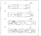
- FIG. 3 is a diagram illustrating a data configuration of encoded data generated by a video encoding device according to an embodiment of the present invention and decoded by the video decoding device, wherein (a) to (d) are pictures, respectively. It is a figure which shows a layer, a slice layer, a tree block layer, and a CU layer. It is the flowchart which illustrated about the flow of the process which divides
- FIG. 1 It is a figure which shows the example of a division
- FIG. 20 is a diagram illustrating an example in which the high frequency component side region in the target block illustrated in FIG. 17 and FIG. 19 is further subdivided into three regions. An example of a VLC table associated with the above three areas is shown.
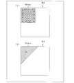
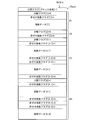
- (A) of the same figure shows the VLC table referred when the value of x or y does not become a positive value more than predetermined. Further, (b) in the figure shows a VLC table that is referred to when the value of x or y does not become a predetermined negative value or less. It is a flowchart shown about an example of the flow of the process encoded / decoded while switching two processes. It is a figure which illustrates about the process which encodes / decodes only 64 coefficients by the side of the low frequency component in an object block. (A) of the figure shows the case of inter prediction, and (b) shows the case of intra prediction. It is a figure shown about an example of the data structure of coefficient coding data.
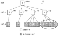
- FIG. 27 shows a flag tree representation example (quadtree representation) representing the division status and coefficient distribution status of the target block shown in FIG. It is a flowchart shown about an example of the flow of a decoding process of a recursive area
- FIG. 2 is a functional block diagram showing a schematic configuration of the moving picture decoding apparatus 1.
- VCEG Video Coding Expert Group
- TMuC Transmission Model Underside
- the moving picture decoding apparatus 1 receives encoded data # 1 obtained by encoding a moving picture by the moving picture encoding apparatus 2.
- the video decoding device 1 decodes the input encoded data # 1 and outputs the video # 2 to the outside.
- the configuration of the encoded data # 1 will be described below.
- the encoded data # 1 exemplarily includes a sequence and a plurality of pictures constituting the sequence.
- FIG. 3 shows the hierarchical structure below the picture layer in the encoded data # 1.
- 3A to 3D are included in the picture layer that defines the picture PICT, the slice layer that defines the slice S, the tree block layer that defines the tree block TBLK, and the tree block TBLK, respectively.
- Picture layer In the picture layer, a set of data referred to by the video decoding device 1 for decoding a picture PICT to be processed (hereinafter also referred to as a target picture) is defined. As shown in FIG. 3A, the picture PICT includes a picture header PH and slices S 1 to S NS (NS is the total number of slices included in the picture PICT).
- the picture header PH includes a coding parameter group referred to by the video decoding device 1 in order to determine a decoding method of the target picture.
- the encoding mode information (entropy_coding_mode_flag) indicating the variable length encoding mode used in encoding by the moving image encoding device 2 is an example of an encoding parameter included in the picture header PH.
- the picture PICT is encoded by LCEC (Low Complexity Entropy Coding) or CAVLC (Context-based Adaptive Variable Length Coding).
- LCEC Low Complexity Entropy Coding
- CAVLC Context-based Adaptive Variable Length Coding
- CABAC Context-based Adaptive Binary Arithmetic Coding
- picture header PH is also referred to as a picture parameter set (PPS).
- PPS picture parameter set
- slice layer In the slice layer, a set of data referred to by the video decoding device 1 for decoding the slice S to be processed (also referred to as a target slice) is defined. As shown in FIG. 3B, the slice S includes a slice header SH and a sequence of tree blocks TBLK 1 to TBLK NC (NC is the total number of tree blocks included in the slice S).
- the slice header SH includes a coding parameter group that the moving image decoding apparatus 1 refers to in order to determine a decoding method of the target slice.
- Slice type designation information (slice_type) for designating a slice type is an example of an encoding parameter included in the slice header SH.
- I slice that uses only intra prediction at the time of encoding (2) P slice that uses unidirectional prediction or intra prediction at the time of encoding, (3) B-slice using unidirectional prediction, bidirectional prediction, or intra prediction at the time of encoding may be used.
- the slice header SH may include a filter parameter referred to by a loop filter (not shown) included in the video decoding device 1.
- Tree block layer In the tree block layer, a set of data referred to by the video decoding device 1 for decoding a processing target tree block TBLK (hereinafter also referred to as a target tree block) is defined.
- the tree block TBLK includes a tree block header TBLKH and coding unit information CU 1 to CU NL (NL is the total number of coding unit information included in the tree block TBLK).
- NL is the total number of coding unit information included in the tree block TBLK.
- the tree block TBLK is divided into units for specifying a block size for each process of intra prediction or inter prediction and conversion.
- the above unit of the tree block TBLK is divided by recursive quadtree partitioning.
- the tree structure obtained by this recursive quadtree partitioning is hereinafter referred to as a coding tree.
- a unit corresponding to a leaf that is a node at the end of the coding tree is referred to as a coding node.
- the encoding node is a basic unit of the encoding process, hereinafter, the encoding node is also referred to as an encoding unit (CU).
- CU encoding unit
- coding unit information (hereinafter referred to as CU information)
- CU 1 to CU NL is information corresponding to each coding node (coding unit) obtained by recursively dividing the tree block TBLK into quadtrees. is there.
- the root of the coding tree is associated with the tree block TBLK.
- the tree block TBLK is associated with the highest node of the tree structure of the quadtree partition that recursively includes a plurality of encoding nodes.
- each coding node is half the size of the coding node to which the coding node directly belongs (that is, the unit of the node one layer higher than the coding node).
- the size that each coding node can take depends on the size designation information of the coding node and the maximum hierarchy depth (maximum hierarchical depth) included in the sequence parameter set SPS of the coded data # 1. For example, when the size of the tree block TBLK is 64 ⁇ 64 pixels and the maximum hierarchical depth is 3, the encoding nodes in the hierarchy below the tree block TBLK have four sizes, that is, 64 ⁇ 64. It can take any of a pixel, 32 ⁇ 32 pixel, 16 ⁇ 16 pixel, and 8 ⁇ 8 pixel.
- the tree block header TBLKH includes an encoding parameter referred to by the video decoding device 1 in order to determine a decoding method of the target tree block. Specifically, as shown in (c) of FIG. 3, tree block division information SP_TBLK that designates a division pattern of the target tree block into each CU, and a quantization parameter difference that designates the size of the quantization step ⁇ qp (qp_delta) is included.
- the tree block division information SP_TBLK is information representing a coding tree for dividing the tree block. Specifically, the shape and size of each CU included in the target tree block, and the position in the target tree block Is information to specify.
- the tree block division information SP_TBLK may not explicitly include the shape or size of the CU.
- the tree block division information SP_TBLK may be a set of flags (split_coding_unit_flag) indicating whether or not the entire target tree block or a partial area of the tree block is divided into four.
- the shape and size of each CU can be specified by using the shape and size of the tree block together.
- the quantization parameter difference ⁇ qp is a difference qp ⁇ qp ′ between the quantization parameter qp in the target tree block and the quantization parameter qp ′ in the tree block encoded immediately before the target tree block.
- CU layer In the CU layer, a set of data referred to by the video decoding device 1 for decoding a CU to be processed (hereinafter also referred to as a target CU) is defined.
- the encoding node is a node at the root of a prediction tree (PT) and a transformation tree (TT).
- PT prediction tree
- TT transformation tree
- the encoding node is divided into one or a plurality of prediction blocks, and the position and size of each prediction block are defined.
- the prediction block is one or a plurality of non-overlapping areas constituting the encoding node.
- the prediction tree includes one or a plurality of prediction blocks obtained by the above division.
- Prediction processing is performed for each prediction block.
- a prediction block that is a unit of prediction is also referred to as a prediction unit (PU).
- intra prediction There are roughly two types of division in the prediction tree: intra prediction and inter prediction.
- inter prediction there are 2N ⁇ 2N (the same size as the encoding node), 2N ⁇ N, N ⁇ 2N, N ⁇ N, and the like.
- the encoding node is divided into one or a plurality of transform blocks, and the position and size of each transform block are defined.
- the transform block is one or a plurality of non-overlapping areas constituting the encoding node.
- the conversion tree includes one or a plurality of conversion blocks obtained by the above division.
- transform processing is performed for each conversion block.
- the transform block which is a unit of transform is also referred to as a transform unit (TU).
- the CU information CU specifically includes a skip flag SKIP, PT information PTI, and TT information TTI.
- the skip flag SKIP is a flag indicating whether or not the skip mode is applied to the target PU.
- the value of the skip flag SKIP is 1, that is, when the skip mode is applied to the target CU, PT information PTI and TT information TTI in the CU information CU are omitted. Note that the skip flag SKIP is omitted for the I slice.
- the PT information PTI is information regarding the PT included in the CU.
- the PT information PTI is a set of information related to each of one or more PUs included in the PT, and is referred to when the moving image decoding apparatus 1 generates a predicted image.
- the PT information PTI includes prediction type information PType and prediction information PInfo.
- Prediction type information PType is information that specifies whether intra prediction or inter prediction is used as a prediction image generation method for the target PU.
- the prediction information PInfo is composed of intra prediction information or inter prediction information depending on which prediction method is specified by the prediction type information PType.
- a PU to which intra prediction is applied is also referred to as an intra PU
- a PU to which inter prediction is applied is also referred to as an inter PU.
- the prediction information PInfo includes information specifying the shape, size, and position of the target PU. As described above, the generation of the predicted image is performed in units of PU. Details of the prediction information PInfo will be described later.
- TT information TTI is information related to TT included in the CU.
- the TT information TTI is a set of information regarding each of one or a plurality of TUs included in the TT, and is referred to when the moving image decoding apparatus 1 decodes residual data.
- a TU may be referred to as a block.
- the TT information TTI includes TT division information SP_TU for designating a division pattern of the target CU into each conversion block, and TU information TUI 1 to TUI NT (NT is assigned to the target CU. The total number of blocks included.
- TT division information SP_TU is information for determining the shape and size of each TU included in the target CU and the position in the target CU.
- the TT division information SP_TU can be realized from information (split_transform_unit_flag) indicating whether or not the target node is divided and information (trafoDepth) indicating the depth of the division.
- each TU obtained by the division can take a size from 32 ⁇ 32 pixels to 2 ⁇ 2 pixels.
- the TU information TUI 1 to TUI NT are individual information regarding one or more TUs included in the TT.
- the TU information TUI includes a quantized prediction residual.
- Each quantized prediction residual is encoded data generated by the video encoding device 2 performing the following processes 1 to 3 on a target block that is a processing target block.
- Process 1 DCT transform (Discrete Cosine Transform) of the prediction residual obtained by subtracting the prediction image from the encoding target image;
- Process 2 Quantize the transform coefficient obtained in Process 1;
- Process 3 Variable length coding is performed on the transform coefficient quantized in Process 2;
- prediction information PInfo As described above, there are two types of prediction information PInfo: inter prediction information and intra prediction information.
- the inter prediction information includes an encoding parameter that is referred to when the video decoding device 1 generates an inter predicted image by inter prediction. More specifically, the inter prediction information includes inter PU division information that specifies a division pattern of the target CU into each inter PU, and inter prediction parameters for each inter PU.
- the inter prediction parameters include a reference image index, an estimated motion vector index, and a motion vector residual.
- the intra prediction information includes an encoding parameter that is referred to when the video decoding device 1 generates an intra predicted image by intra prediction. More specifically, the intra prediction information includes intra PU division information that specifies a division pattern of the target CU into each intra PU, and intra prediction parameters for each intra PU.
- the intra prediction parameter is a parameter for designating an intra prediction method (prediction mode) for each intra PU.
- the video decoding device 1 generates a predicted image for each PU, generates a decoded image # 2 by adding the generated predicted image and a prediction residual decoded from the encoded data # 1, and generates The decoded image # 2 is output to the outside.
- An encoding parameter is a parameter referred in order to generate a prediction image.
- the encoding parameters include PU size and shape, block size and shape, and original image and Residual data with the predicted image is included.
- side information a set of all information excluding the residual data among the information included in the encoding parameter.
- the present invention is not limited to this, and the present invention can also be applied to a case where PU and TU are units smaller than CU.
- a picture (frame), a slice, a tree block, a block, and a PU to be decoded are referred to as a target picture, a target slice, a target tree block, a target block, and a target PU, respectively.
- the size of the tree block is, for example, 64 ⁇ 64 pixels
- the size of the PU is, for example, 64 ⁇ 64 pixels, 32 ⁇ 32 pixels, 16 ⁇ 16 pixels, 8 ⁇ 8 pixels, 4 ⁇ 4 pixels, or the like.
- these sizes are merely examples, and the sizes of the tree block and PU may be other than the sizes shown above.
- FIG. 2 is a functional block diagram showing a schematic configuration of the moving picture decoding apparatus 1.
- the moving image decoding apparatus 1 includes a variable length code demultiplexing unit 11, a TU information decoding unit 12, an inverse quantization / inverse transform unit 13, a predicted image generation unit 14, an adder 15, and a frame memory 16. It has.
- variable-length code demultiplexing unit 11 demultiplexes the encoded data # 1 for one frame input to the video decoding device 1 to obtain various kinds of information included in the hierarchical structure shown in FIG. To separate.
- the variable length code demultiplexer 11 refers to information included in various headers and sequentially separates the encoded data # 1 into slices and tree blocks.
- the various headers include (1) information about the method of dividing the target picture into slices, and (2) information about the size, shape, and position of the tree block belonging to the target slice. .
- variable length code demultiplexing unit 11 refers to the tree block division information SP_TBLK included in the tree block header TBLKH, and divides the target tree block into CUs. In addition, the variable-length code demultiplexer 11 acquires TT information TTI and PT information PTI for the target CU.
- variable length code demultiplexing unit 11 supplies the TU information TUI included in the TT information TTI obtained for the target CU to the TU information decoding unit 12 in a predetermined order. In addition, the variable-length code demultiplexing unit 11 supplies the PT information PTI obtained for the target CU to the predicted image generation unit 14.
- the TU information decoding unit 12 decodes the TU information TUI supplied from the variable length code demultiplexing unit 11 to generate decoded TU information TUI ′.
- the TU information decoding unit 12 decodes the quantized prediction residual from the TU information TUI for the target block.
- the quantized prediction residual for the target block can be expressed in a form in which quantized transform coefficients are arranged in a two-dimensional matrix.
- a two-dimensional matrix representation of quantized transform coefficients is referred to as a coefficient matrix.
- the TU information decoding unit 12 supplies the decoded TU information TUI ′ to the inverse quantization / inverse transform unit 13. Details of the operation of the TU information decoding unit 12 will be described later.
- the inverse quantization / inverse transform unit 13 performs inverse quantization / inverse transform of the quantized prediction residual for each block for the target CU based on the decoded decoded TU information TUI ′ supplied from the TU information decoding unit 12. I do.
- the inverse quantization / inverse transform unit 13 performs inverse quantization and inverse DCT transform (Inverse Discrete Cosine Transform) on the quantized prediction residual included in the decoded TU information TUI ′, so that for each target PU, for each pixel.
- the prediction residual D is restored.
- the inverse quantization / inverse transform unit 13 supplies the restored prediction residual D to the adder 15.
- the predicted image generation unit 14 For each PU included in the target CU, the predicted image generation unit 14 refers to a local decoded image P ′ that is a decoded image around the PU, and generates a predicted image Pred by intra prediction or inter prediction. The predicted image generation unit 14 supplies the predicted image Pred generated for the target CU to the adder 15.
- the adder 15 adds the predicted image Pred supplied from the predicted image generation unit 14 and the prediction residual D supplied from the inverse quantization / inverse transform unit 13, thereby obtaining the decoded image P for the target CU. Generate.
- the decoded image P that has been decoded is sequentially recorded in the frame memory 16.
- decoded images corresponding to all tree blocks decoded before the target tree block are stored. It is recorded.
- Decoded image # 2 corresponding to # 1 is output to the outside.
- the moving picture coding apparatus 2 scans a coefficient matrix representing a set of coefficients in the target block in a predetermined order.
- Scan is a process of converting the coordinates of the coefficients in the coefficient matrix into a one-dimensional scan order index.
- the converted coefficients are stored and held in a one-dimensional array.
- For scanning a conventionally known zigzag scanning order or the like can be used.
- the DC coefficient at the upper left position to the coefficient of the highest frequency component at the lower right position are scanned based on the zigzag scan order.
- the coefficient value of the high frequency component tends to be zero or close to zero, whereas the coefficient value of the low frequency component has a characteristic that it is likely that the value is not zero or is large. For this reason, the zigzag scan has a scan order in which the low-frequency component coefficients are scanned quickly.
- a coefficient coding process is performed after scanning.
- the coefficient encoding process is performed in the reverse order of the scan.
- this processing order is also called reverse zigzag scanning. That is, the encoding process is performed by a reverse zigzag scan on the coefficient matrix. Further, when describing the encoding processing order, for convenience, the description will be made based on a coefficient matrix.
- the scan order may be adaptively changed to a method other than the zigzag scan, for example, the same order as the raster scan.
- coefficient encoded data encoded by the moving image encoding apparatus 2 will be described.
- the last non-zero coefficient is encoded.
- encoding in the run mode is performed under a predetermined condition.
- the run mode ends by satisfying the run mode end condition the remaining coefficients are encoded in the level mode. In this way, all the coefficients are encoded.
- the last non-zero coefficient is encoded by the last non-zero coefficient position last_pos, the last non-zero coefficient level level, and the last non-zero coefficient sign sign.
- the coefficient level means the absolute value of the coefficient.
- last_pos takes a value in the form of a scan order index. When the last non-zero coefficient is the 10th in the scanning order (the DC coefficient is the first) and the value is “ ⁇ 1”, it is as follows.
- the run mode is a mode for encoding the number of consecutive zero coefficients (0 run). Under what conditions the encoding in the run mode is performed will be described later.
- Non-Patent Documents 1 and 2 the case where a coefficient whose level is 2 or more appears is used as one of the end conditions of the run mode.
- Level mode is a mode in which even zero coefficients are encoded one by one. In the level mode, for each coefficient, the coefficient level and the sign of the coefficient sign are encoded.
- the case where the value of the coefficient to be encoded is “ ⁇ 6” and the case where the coefficient to be encoded is a zero coefficient (value is “0”) are as follows.
- the syntax element may be encoded with a name or definition different from the above.
- the level level of the coefficient of the run mode is the syntax of isLevelOne (level is 1), and in addition to this, the level_magnitude_minus2 (when the coefficient value is 2 or more, encoding is a level obtained by subtracting 2). It may be encoded as an element (see “level_magnitude_minus2” in Non-Patent Documents 1 and 2).
- the level may be encoded as a syntax element of last_pos_level for the last non-zero coefficient.
- level of the non-run mode may be encoded as a syntax element of level_magnitude.
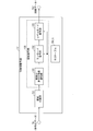
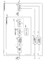
- FIG. 1 is a functional block diagram illustrating a configuration example of the TU information decoding unit 12.
- the TU information decoding unit 12 decodes data related to coefficients among the encoded data included in the TU information TUI.
- a configuration for the TU information decoding unit 12 to decode the encoded quantized prediction residual, that is, coefficient encoded data will be described below.
- the TT information decoding unit 12 is not limited to this, and can decode data other than the coefficient encoded data included in the encoded data, for example, side information.
- the TU information decoding unit 12 includes a VLC table TBL11, a region dividing unit (transform unit dividing unit) 121, and a region decoding unit (transform coefficient decoding unit) 122.
- the TU information decoding unit 12 decodes the TU information TUI for a 16 ⁇ 16 size target block and outputs the decoded TU information TUI ′.
- the present invention is not limited to this, and the size of the target block decoded by the TU information decoding unit 12 may be 64 ⁇ 64, 32 ⁇ 32, or the like.
- the VLC table TBL11 is a table in which a bit number (code), a code number that can be mutually converted, and a parameter to be decoded are associated with each other.
- the VLC table TBL11 is referred to in the decoding process of the area decoding unit 122.
- VLC table TBL11 for example, a table defined for an 8 ⁇ 8 size encoding unit is used. That is, for the VLC table TBL11, an 8 ⁇ 8 size smaller than the input conversion unit (or encoding unit) 16 ⁇ 16 size is used.
- VLC tables TBL11 are defined according to the context in the decoding process so that an adaptive decoding process can be performed.
- the context for example, the position of the coefficient being processed, the attribute of the target block (pixel type such as luminance / color difference, and prediction method) and the like can be used.
- the area dividing unit 121 divides the target block into a plurality of areas.
- each area obtained by the division by the area dividing unit 121 is referred to as a decoding area.
- the region dividing unit 121 divides a 16 ⁇ 16 size target block into four 8 ⁇ 8 size decoding regions.
- the present invention is not limited to this, and various methods can be adopted as the dividing method of the area dividing unit 121. The modification will be described in detail later.
- the area decoding unit 122 performs a decoding process for each of the decoding areas obtained by dividing the target block by the area dividing unit 121 while referring to the VLC table TBL11 defined according to the size of the decoding area. Do.
- the region decoding unit 122 performs a decoding process while referring to the VLC table TBL11 defined for an 8 ⁇ 8 size encoding unit according to a context.
- the region decoding unit 122 includes a final non-zero coefficient decoding unit 101, a run mode decoding unit 102, and a level mode decoding unit 103.
- the last non-zero coefficient decoding unit 101 decodes the last non-zero coefficient for a decoding area to be decoded (hereinafter referred to as a target decoding area). More specifically, the last non-zero coefficient decoding unit 101 decodes last_pos, level, and sign included in the coefficient encoded data corresponding to the target decoding area.
- the run mode decoding unit 102 decodes the coefficient encoded in the run mode from the coefficient encoded data for the target decoding area. That is, the run mode decoding unit 102 decodes run, level, and sign encoded in the run mode from the coefficient encoded data while referring to the VLC table TBL11 corresponding to the context.
- the decoding process performed by the run mode decoding unit 102 is referred to as a run mode decoding process.
- the run mode decoding unit 102 repeatedly performs the run mode decoding process until the run mode end condition is satisfied.
- the run mode end condition include a case where the value of the decoded coefficient exceeds a threshold value and a case where a predetermined number of coefficients are decoded.
- the run mode decoding unit 102 causes the level mode decoding unit 103 to start decoding in the level mode.
- the level mode decoding unit 103 decodes the coefficient encoded in the level mode from the coefficient encoded data for the target decoding area. That is, the level mode decoding unit 103 decodes level and sign encoded in the level mode from the coefficient encoded data while referring to the VLC table TBL11 corresponding to the context.
- the decoding process performed by the level mode decoding unit 103 is referred to as a level mode decoding process. Further, the level mode decoding unit 103 repeatedly performs the level mode decoding process until the DC component coefficient is decoded.
- the area decoding unit 122 outputs the decoded TU information TUI ′ including the coefficient obtained by the decoding process.
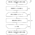
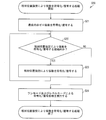
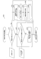
- FIG. 4 is a flowchart exemplifying the flow of the process S10 in which the target block is divided into regions and the coefficients are encoded / decoded.
- the difference between the encoding process of the moving image encoding apparatus 2 and the decoding process of the moving image decoding apparatus 1 is whether the encoding process or the decoding process is performed.
- the decoding process is almost the same. Therefore, in FIG. 4, the encoding process of the moving image encoding apparatus 2 and the decoding process of the moving image decoding apparatus 1 are collectively shown.
- the area dividing unit 121 divides the target block (S11).
- the loop LP1 for each divided decoding area is entered (S12).
- the region decoding unit 122 decodes the coefficient included in the coefficient encoded data for the target decoding region (S13).
- the last non-zero coefficient decoding unit 101 decodes the last non-zero coefficient in the target decoding area.
- the run mode decoding unit 102 performs the run mode decoding process until the run mode end condition is satisfied.
- the level mode decoding unit 103 After the run mode ends, the level mode decoding unit 103 performs a level mode decoding process. When the decoding process for the target decoding area is completed in this way, the process returns to the beginning of the loop LP1 (from S14 to S12), and the decoding process is further performed for the next target decoding area.
- the loop LP1 ends. Thereafter, the process S10 for dividing the region and decoding the coefficients ends.
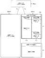
- FIG. 5 shows a 16 ⁇ 16 size target block (conversion unit) BLK.
- FIG. 6 shows an example in which the decoding process is performed by dividing the target block BLK into four 8 ⁇ 8 size areas.
- the region dividing unit 121 divides the 16 ⁇ 16 size target block BLK into four 8 ⁇ 8 size decoding regions (sub units) R11 to R14 as shown in FIG.
- the area decoding unit 122 processes each decoding area shown in FIG. 6 in the order of decoding areas R11, R12, R13 and R14.
- the arrows shown in the decoding regions R11 to R14 indicate the scan order. That is, the scan order of the decoding regions R11 to R14 is a zigzag scan.
- the last non-zero coefficient decoding unit 101 first decodes the last non-zero coefficient in the scan order. Then, by the run mode decoding process and the level mode decoding process, the last non-zero coefficient to the DC component coefficient are decoded by reverse zigzag scanning.
- the decoding process of the decoding area R11 is completed, the decoding process is similarly performed on the decoding areas R12, R13, and R14.
- the decoding process is performed by the conventional decoding method for the 8 ⁇ 8 size encoding unit. That is, in the decoding process of the decoding regions R11 to R14, a conventional decoding method that decodes the last non-zero coefficient and performs the run mode decoding process and the level mode decoding process can be used.
- Modification 1-1 [Determination of Existence of Non-zero Coefficient]
- the area decoding unit 122 may perform a decoding process according to the presence or absence of a non-zero coefficient.
- the region decoding unit 122 may be configured as follows.
- the region decoding unit 122 decodes the non-zero coefficient flag and determines whether or not there is a non-zero coefficient. If the non-zero coefficient flag indicates that there is no non-zero coefficient in the target decoding area, the area decoding unit 122 skips the decoding process in the target area.
- FIG. 7 shows an example in which the decoding regions R11, R13, and R13 have non-zero coefficients and the decoding region R12 has no non-zero coefficients. That is, “0” shown in the decoding region R12 indicates that there is no non-zero coefficient.
- non-zero coefficient flag for example, “0” is encoded when there is no non-zero coefficient, and “1” is encoded when there is a non-zero coefficient.
- the regions R11, R13, and R14 have non-zero coefficients, and the region R12 has no non-zero coefficients. Therefore, “1011” is encoded as the non-zero coefficient flag. Note that a pattern such as “1011” of the non-zero coefficient flag may be subjected to variable length encoding according to the appearance frequency of the pattern without being fixed length encoded with 4 bits as it is.
- the region decoding unit 122 performs a decoding process on the decoding region R11.
- the region decoding unit 122 skips the decoding process for the decoding region R12.
- the region decoding unit 122 For the remaining decoding regions R13 and R14, as in the decoding region R11, the non-zero coefficient flag “1” indicating that there is a non-zero coefficient is encoded, so the region decoding unit 122 performs the decoding regions R13 and R14. Decoding processing is performed for each of the above.
- Modification 1-2 [Change the processing method according to the position of the decoding area] [1] Change of scanning method In the above description, zigzag scanning is adopted as the scanning method of each decoding area, but the scanning method may be changed according to the position of the decoding area.
- horizontal scanning may be employed in the decoding region R12 located at the upper right in the target block BLK.
- vertical scanning may be employed in the decoding region R13 located at the lower left in the target block BLK.
- zigzag scanning may be employed in the decoding regions R11 and R14.
- the run mode decoding process and the level mode decoding process are performed in the decoding process of each decoding area.
- the run mode decoding process or the level mode decoding process is performed depending on the position of the decoding area. It is good also as a structure which performs either.
- the decoding process may be performed only by the run mode decoding process.
- VLC table to be referenced and the code number calculation method may be changed according to the position of the decoding area.
- a VLC table for converting a bit string indicating a code number into a set of ⁇ run, level ⁇ parameters may be changed according to the position of each decoding area.
- the zero coefficient tends to increase, and in the decoding region on the low frequency component side, the non-zero coefficient increases and the run tends to be shortened.
- FIG. 12 shows an example of the VLC table TBL11 for converting a set of ⁇ run, level ⁇ parameters into code numbers.
- FIG. 13 shows an example in which the VLC tables T1 and T2 are associated with each decoding area. As shown in FIG. 13, the decoding area R11 is associated with the VLC table T2, and the decoding areas R12 to R14 are associated with the VLC table T1.
- the run mode decoding unit 102 refers to the VLC table T2 in the run mode decoding process of the decoding region R11 according to the association shown in FIG.
- the run tends to be short, and therefore, by assigning a smaller code number to a combination of ⁇ run, level ⁇ having a short run, the coding efficiency can be improved.
- the run mode decoding unit 102 refers to the VLC table T1 in the run mode decoding process of the decoding regions R12 to 14 in accordance with the association shown in FIG.
- the present invention is not limited to this, and a conversion process equivalent to the VLC tables T1 and T2 is realized by calculation. It doesn't matter.
- the run mode decoding unit 102 may be configured to refer to mutually different VLC tables in the decoding regions R11 to R14.
- the area decoding unit 122 may count the appearance frequency of parameter values and rewrite the code number of the VLC table according to the appearance frequency.
- the area decoding unit 122 rewrites the code number of the parameter value with a high appearance frequency to a smaller one (with a shorter code), and increases the code number of the parameter value with a lower appearance frequency (with a longer code). You may rewrite it as a thing.
- the code number CN-1 is assigned to the value y of a certain parameter, and the code number CN is assigned to the value x of another parameter.
- region decoding unit 122 refers to x in the VLC table T3 before optimization and the corresponding code number CN.
- the area decoding unit 122 decrements the code number CN by 1 and increments the code number corresponding to x to CN-1.
- the area decoding unit 122 increments the code number of y originally corresponding to CN-1 by 1 and associates it with CN.
- optimization such a code number carry-up process is referred to as optimization.
- a VLC table T4 shown in FIG. 14 is a table obtained after the optimization.
- the region decoding unit 122 sets the code number corresponding to x to CN-2.
- the region decoding unit 122 dynamically updates the VLC table during the decoding process so that a short code number is assigned according to the appearance frequency of the parameter value to be decoded.
- the speed of the adaptation speed can be expressed as a size that decrements the code number, for example. That is, it can be said that the adaptation speed is faster when the code number decrement is “2” than when the code number is decremented by “1”.
- the amount of increment at the time of optimization is set to “0” in the decoding region on the high frequency component side, and “1” on the low frequency component side. Good.
- a configuration may be adopted in which optimization is not performed in the decoding region on the high frequency component side.
- the reason for adopting this configuration is as follows. In other words, the run tends to be long on the high frequency component side, and there is a low possibility that a specific ⁇ run, level ⁇ will occur frequently. For this reason, according to the said structure, the increase in the computational complexity by performing an optimization whenever the value of a parameter appears can be prevented.
- the run mode end condition may be changed according to the position of the decoding area.
- the run mode end condition may be tightened in the decoding region on the high frequency component side, and the run mode end condition may be relaxed in the decoding region on the low frequency component side. That is, it is only necessary to make the run mode easier to end in the decoding area located at the upper left in the target block. Further, the level mode decoding process may not be performed in the decoding region on the high frequency component side.
- the absolute value of the coefficient tends to be small. For this reason, there is a high possibility that the run will be long in the decoding region on the high frequency component side. Therefore, it is preferable to execute the run mode decoding process as much as possible.
- the run mode decoding unit 102 may determine whether or not to start the run mode decoding process. For example, the run mode decoding unit 102 starts the run mode decoding process when “the absolute value of the coefficient can be determined to be small overall” based on data that can be referred to when the last non-zero coefficient is decoded. Then, it may be determined.
- the run mode decoding unit 102 executes the run mode decoding process because there is a high possibility that the run will be long.
- data that can be referred to when the last non-zero coefficient is decoded include, for example, prediction information of the target block, information about the last non-zero coefficient, and other encoded and already decoded on the encoder side. Flag.
- the run mode decoding unit 102 may skip the run mode decoding process.
- threshold values for various determinations in the coefficient decoding process may be changed according to the position of the decoding area.
- Modified example 1-3 [Determining whether to divide according to the prediction mode of the target block]
- the region dividing unit 121 may be configured to determine the presence or absence of division according to the prediction mode of the target block.
- the region dividing unit 121 may perform division when the prediction mode of the target block is intra prediction, and may not perform division when the prediction mode is inter prediction.
- the region decoding unit 122 decodes only the first to 64th coefficients in the scan order in the target block. You may make it do. That is, in this case, the region decoding unit 122 may decode only 64 coefficients on the upper left side of the target block.
- Modification 1-4 [Number and Size of Regions]
- the region dividing unit 121 has been described as dividing the target block into four decoding regions.
- the present invention is not limited to this, and the area dividing unit 121 may divide the target block into more than four areas.
- the target block is not limited to 16 ⁇ 16 size.
- the target block may be 32 ⁇ 32 size or 64 ⁇ 64 size.
- the area dividing unit 121 may divide the target block into four or more decoding areas as follows.
- the area dividing unit 121 may divide the target block into 64 8 ⁇ 8 size decoding areas.
- the area dividing unit 121 may divide the target block into 16 16 ⁇ 16 size decoding areas.
- the area dividing unit 121 may divide the target block into four 32 ⁇ 32 size decoding areas.
- the decoding area obtained by dividing the target block by the area dividing unit 121 is not limited to a square area.
- the decoding area may be a rectangle.
- the target block is divided into two, an upper left 8 ⁇ 8 size decoding area (corresponding to decoding area R11 in FIG. 5) and other decoding areas (corresponding to decoding areas R12 to R14 in FIG. 5) May be.
- each decoding area may not be the same.
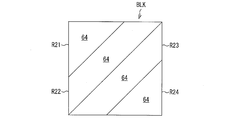
- the target block may be divided into 64 coefficients in the zigzag scan order to obtain a decoding area.
- the target block may be divided into decoding regions R21 to R24.
- the number “64” shown in the decoding areas R21 to R24 indicates that 64 coefficients are included in the area.
- the decoding region R21 is a region including DC coefficients, and the shape thereof is represented by a right triangle in the figure.
- the shapes of the decoding regions R22 and R23 are each represented by a trapezoid.
- the decoding region R24 is a region on the most high frequency component side among the regions, and the shape thereof is represented by a right triangle.
- the shapes of the regions R21 and R24 are shown as right triangles, and the shapes of the regions R22 and R23 are shown as trapezoids. Please note that it does not become trapezoid.
- each decoding area and the number of coefficients included in each decoding area may not be the same.
- the area dividing unit 121 can arbitrarily divide the target block into a plurality of decoding areas having a size smaller than the size of the target block.
- Modification 1-5 [Processing Order of Decoding Area]
- the area decoding unit 122 performs the decoding process in the order of the decoding areas R11, R12, R13, and R14 (so-called raster scan order).
- the present invention is not limited to this, and the area decoding unit 122 may perform the decoding process in an order other than this.
- the region decoding unit 122 may perform the decoding process in the order of the decoding regions R14, R13, R12, and R11, or as another example, in the order of the decoding regions R11, R13, R12, and R14. Further, when the number of decoding areas is more than four, for example, when the number is 16, the processing may be performed in the zigzag scan order.
- the moving image encoding device 2 is a device that generates and outputs encoded data # 1 by encoding the input image # 10.
- FIG. 10 is a functional block diagram showing the configuration of the moving image encoding device 2.
- the moving image encoding device 2 includes an encoding setting unit 21, an inverse quantization / inverse conversion unit 22, a predicted image generation unit 23, an adder 24, a frame memory 25, a subtractor 26, a conversion / A quantization unit 27 and a variable length coding unit 28 are provided.
- the encoding setting unit 21 generates image data related to encoding and various setting information based on the input image # 10.
- the encoding setting unit 21 generates the next image data and setting information.
- the encoding setting unit 21 generates the CU image # 100 for the target CU by sequentially dividing the input image # 10 into slice units and tree block units.
- the encoding setting unit 21 generates header information H ′ based on the result of the division process.
- the header information H ′ includes (1) information about the size and shape of the tree block belonging to the target slice and the position in the target slice, and (2) the size, shape and shape of the CU belonging to each tree block.
- the encoding setting unit 21 refers to the CU image # 100 and the CU information CU 'to generate PT setting information PTI'.
- the PT setting information PTI ' includes information on all combinations of (1) possible division patterns of the target CU for each PU and (2) prediction modes that can be assigned to each PU.
- the encoding setting unit 21 supplies the CU image # 100 to the subtractor 26. In addition, the encoding setting unit 21 supplies the header information H ′ to the variable length encoding unit 28. Also, the encoding setting unit 21 supplies the PT setting information PTI ′ to the predicted image generation unit 23.
- the inverse quantization / inverse transform unit 22 performs inverse quantization and inverse DCT transform (Inverse Discrete Cosine Transform) on the quantization prediction residual for each block supplied from the transform / quantization unit 27, Restore the prediction residual for each block.
- inverse quantization and inverse DCT transform Inverse Discrete Cosine Transform
- the inverse quantization / inverse transform unit 22 integrates the prediction residual for each block according to the division pattern specified by the TT division information (described later), and generates the prediction residual D for the target CU.
- the inverse quantization / inverse transform unit 22 supplies the prediction residual D for the generated target CU to the adder 24.
- the predicted image generation unit 23 refers to the locally decoded image P ′ and the PT setting information PTI ′ recorded in the frame memory 25 to generate a predicted image Pred for the target CU.
- the predicted image generation unit 23 sets the prediction parameter obtained by the predicted image generation process in the PT setting information PTI ′, and transfers the set PT setting information PTI ′ to the variable length encoding unit 28. Note that the predicted image generation process performed by the predicted image generation unit 23 is the same as that performed by the predicted image generation unit 14 included in the video decoding device 1, and thus the description thereof is omitted here.
- the adder 24 adds the predicted image Pred supplied from the predicted image generation unit 23 and the prediction residual D supplied from the inverse quantization / inverse transform unit 22 to thereby obtain the decoded image P for the target CU. Generate.
- Decoded decoded image P is sequentially recorded in the frame memory 25.
- decoded images corresponding to all tree blocks decoded before the target tree block for example, all tree blocks preceding in the raster scan order
- the time of decoding the target tree block It is recorded.
- the subtractor 26 generates a prediction residual D for the target CU by subtracting the prediction image Pred from the CU image # 100.
- the subtractor 26 supplies the generated prediction residual D to the transform / quantization unit 27.
- the transform / quantization unit 27 performs a DCT transform (Discrete Cosine Transform) and quantization on the prediction residual D to generate a quantized prediction residual.
- DCT transform Discrete Cosine Transform
- the transform / quantization unit 27 refers to the CU image # 100 and the CU information CU 'and determines a division pattern of the target CU into one or a plurality of blocks. Further, according to the determined division pattern, the prediction residual D is divided into prediction residuals for each block.
- the transform / quantization unit 27 generates a prediction residual in the frequency domain by performing DCT transform (DiscretecreCosine Transform) on the prediction residual for each block, and then quantizes the prediction residual in the frequency domain. Thus, a quantized prediction residual for each block is generated.
- DCT transform DiscretecreCosine Transform
- the transform / quantization unit 27 generates the quantization prediction residual for each block, TT division information that specifies the division pattern of the target CU, information about all possible division patterns for each block of the target CU, and TT setting information TTI ′ including is generated.
- the transform / quantization unit 27 supplies the generated TT setting information TTI ′ to the inverse quantization / inverse transform unit 22.
- the transform / quantization unit 27 generates TU setting information TUI ′ including the quantization prediction residual of the target block, and supplies the TU setting information TUI ′ to the variable length encoding unit 28.
- variable length encoding unit 28 generates and outputs encoded data # 1 based on the TU setting information TUI ', the PT setting information PTI', and the header information H '. Details of the variable length coding unit 28 will be described below.
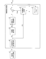
- FIG. 11 is a block diagram illustrating a configuration example of the variable length coding unit 28.
- variable length coding unit 28 includes a TU information coding unit 280, a header information coding unit 40, a PTI information coding unit 41, and a coded data multiplexing unit 42.
- the TU information encoding unit 280 encodes the TU setting information TUI ′ and supplies it to the encoded data multiplexing unit 42.
- the header information encoding unit 40 encodes the header information H ′ and supplies the encoded header information H ′ to the encoded data multiplexing unit 42.
- the PTI information encoding unit 41 encodes the PTI information PTI ′ and supplies the encoded PTI information PTI ′ to the encoded data multiplexing unit 42.
- the encoded data multiplexing unit 42 multiplexes the TU setting information TUI ′, the header information H ′, and the PTI information PTI ′ to generate encoded data # 1, and outputs it.
- the configuration of the TU information encoding unit 280 will be described in more detail as follows.
- a configuration for encoding coefficient prediction data by encoding a quantized prediction residual, that is, a coefficient matrix, included in the TU setting information TUI ' will be described.
- the TU information encoding unit 280 encodes the TU information TUI for the 16 ⁇ 16 size target block and outputs the encoded TU information TUI ′.
- the present invention is not limited to this, and the size of the target block encoded by the TU information encoding unit 280 may be 64 ⁇ 64, 32 ⁇ 32, or the like.
- the TU information encoding unit 280 includes a VLC table TBL21, a region dividing unit (transform unit dividing unit) 281 and a region encoding unit (transform coefficient coding unit) 282.
- the VLC table TBL21 is a table in which the correspondence between each parameter and a code that is a bit string of encoded data is defined.
- VLC table TBL21 for example, a table defined for an 8 ⁇ 8 size encoding unit is used. That is, for the VLC table TBL21, an 8 ⁇ 8 size smaller than the input conversion unit (or encoding unit) 16 ⁇ 16 size is used.
- VLC tables TBL21 are defined according to the context in the encoding process so that an adaptive encoding process can be performed.
- the area dividing unit 281 divides the target block into a plurality of areas.
- each area obtained by the division of the area dividing unit 281 is referred to as an encoding area.
- the area dividing unit 281 divides a 16 ⁇ 16 size target block into four coding areas. That is, the region dividing unit 281 divides a 16 ⁇ 16 size target block into four 8 ⁇ 8 size coding regions.
- the area dividing unit 281 can divide the target block, for example, as shown in FIG. In the following description, the decoding regions R11 to R14 shown in FIG. 5 are read as coding regions R11 to R14.
- the area dividing unit 281 divides the target block BLK into coding areas R11 to R14.
- the present invention is not limited to this, and various methods can be applied to the dividing method of the region dividing unit 281. The modification will be described in detail later.
- the area coding unit 282 performs coding for each of the coding areas obtained by dividing the target block by the area dividing unit 281 while referring to the VLC table TBL21 defined according to the size of the coding area. Process. That is, in the following, an example in which the region encoding unit 282 performs the encoding process while referring to the VLC table TBL21 defined for the 8 ⁇ 8 size according to the context will be described.
- the region encoding unit 282 includes a final non-zero coefficient encoding unit 201, a run mode encoding unit 202, and a level mode encoding unit 203.
- the last non-zero coefficient encoding unit 201 encodes the last non-zero coefficient for a coding area to be encoded (hereinafter referred to as a target coding area). More specifically, the last non-zero coefficient coding unit 201 codes last_pos, level, and sign for the last non-zero coefficient included in the coefficient matrix corresponding to the target coding region.
- the run mode encoding unit 202 performs a run mode encoding process on the coefficient matrix for the target encoding region. That is, the run mode encoding unit 202 sequentially encodes run, level, and sign for the non-zero coefficients included in the coefficient matrix by the run mode while referring to the VLC table TBL21 corresponding to the context.
- the encoding process performed by the run mode encoding unit 202 is referred to as a run mode encoding process.
- the run mode encoding unit 202 repeats the run mode encoding process until the run mode end condition is satisfied.
- the run mode end condition include a case where the value of the encoded coefficient exceeds a threshold value and a case where a predetermined number of coefficients are encoded.
- the run mode encoding unit 202 causes the level mode encoding unit 203 to start encoding in the level mode.
- the level mode encoding unit 203 encodes the coefficients included in the coefficient matrix in the target encoding area in the level mode. That is, the level mode encoding unit 203 sequentially encodes the level and sign of the coefficients included in the coefficient matrix in the level mode while referring to the VLC table TBL21 corresponding to the context.
- the encoding process performed by the level mode encoding unit 203 is referred to as a level mode encoding process. Further, the level mode encoding unit 203 repeatedly performs the level mode encoding process until the first coefficient is encoded in the scan order of the target encoding region.
- the area encoding unit 282 outputs encoded TU setting information TUI ′ including the coefficient obtained by the encoding process.
- region encoding unit 282 can perform the encoding process as shown in FIG.
- the decoding regions R11 to R14 shown in FIG. 6 are read as coding regions R11 to R14.
- the region encoding unit 282 performs encoding processing in the order of the encoding regions R11, R12, R13, and R14 shown in FIG.
- the last non-zero coefficient decoding unit 101 first decodes the last non-zero coefficient in the scan order. Then, the run mode decoding process and the level mode decoding process decode from the last non-zero coefficient to the first coefficient in the scan order of the target coding region in the reverse order of the scan order.
- Modified example 1-1 ′ [Determination of presence / absence of non-zero coefficient]
- the region encoding unit 282 included in the moving image encoding device 2 determines whether or not there is a non-zero coefficient for each encoding region, encodes a non-zero coefficient flag indicating the determination result, and includes it in the coefficient encoded data It is good. Further, in such a configuration, the region encoding unit 282 can omit the encoding of the coefficient for the encoding region where there is no non-zero coefficient.
- coding region and the non-zero coefficient flag are substantially the same as those already described in Modification 1-1 of the video decoding device 1, and thus description thereof is omitted here.
- “decoding region”, “decoding process”, and “region decoding unit 122” in the description of Modification 1-1 are respectively referred to as “encoding region”, “encoding process”, and “region encoding unit 282”. ".”
- Modification 1-2 ′ [Processing method is changed according to the position of the coding area] [1] Change of scanning method
- the zigzag scanning is adopted as the scanning method of each coding area.
- the scanning method may be changed according to the position of the coding area.
- the specific scanning method is the same as that described in, for example, the modified example 1-2 [1] of the video decoding device 1, and thus the description thereof is omitted here.
- the “decoding region”, “decoding process”, and “region decoding unit 122” in the description of the modified example 1-2 [1] are respectively referred to as “encoding region”, “encoding process”, and “region code”. It shall be read as “the conversion unit 282”.
- the run mode encoding process and the level mode encoding process are performed in the encoding process of each encoding area.
- the run mode encoding process is performed according to the position of the encoding area. It is good also as composition which performs.
- a specific processing example is the same as that described in Modification 1-2 [2] of the video decoding device 1, for example, and will not be described here.
- the “decoding region”, “decoding process”, and “region decoding unit 122” in the description of the modified example 1-2 [2] are respectively referred to as “encoding region”, “encoding process”, and “region code”. It shall be read as “the conversion unit 282”.
- VLC table to be referred to and the code number calculation method may be changed according to the position of the encoding area.
- a VLC table for converting a bit string indicating a code number into a set of ⁇ run, level ⁇ parameters may be changed according to the position of each coding area.
- a specific processing example is the same as that described in Modification 1-2 [3] of the moving picture decoding apparatus 1, for example, and thus the description thereof is omitted here.
- the “decoding region”, “decoding process”, and “region decoding unit 122” in the description of the modified example 1-2 [3] are respectively referred to as “encoding region”, “encoding process”, and “region code”. It shall be read as “the conversion unit 282”.
- the area encoding unit 282 may count the appearance frequency of parameter values and rewrite the code number of the VLC table according to the appearance frequency.
- the area encoding unit 282 rewrites the code number of the parameter value having a high appearance frequency to a smaller one (with a shorter code), and increases the code number of the parameter value with a lower appearance frequency (having a longer code). ) You may rewrite it to something.
- a specific processing example is the same as that described in, for example, the modification 1-2 [4-1] of the video decoding device 1, and thus the description thereof is omitted here.
- the “decoding region”, “decoding process”, and “region decoding unit 122” in the description of the modified example 1-2 [4-1] are respectively referred to as “encoding region”, “encoding process”, and “ It shall be read as “region encoding unit 282”.
- the run mode end condition may be changed according to the position of the coding area. Further, the run mode start condition may be determined according to the position of the coding region. Details thereof are the same as those described in the description of Modification 1-2 [5] of the video decoding device 1, and thus detailed description thereof is omitted here.
- Modified example 1-3 ′ [Determining whether to divide according to the prediction mode of the target block]
- the region dividing unit 281 may be configured to determine the presence or absence of division according to the prediction mode of the target block.
- the specific processing is the same as that described in the modification 1-3 of the video decoding device 1, and thus the description thereof is omitted here.
- Modified example 1-4 ′ [Number and size of regions]
- the area dividing unit 281 may divide the target block into more than four areas.
- the specific processing is the same as that described in, for example, the modified example 1-4 of the video decoding device 1, and thus the description thereof is omitted here.
- Modification 1-5 ′ [Processing order of coding area]
- the scan order of the encoding processing by the region encoding unit 282 is not limited to the above-described example.
- the region encoding unit 282 may be configured to perform the same processing as the processing described in Modification 1-5 of the video decoding device 1.
- [Modification] of the video decoding device 1 can be applied to the video encoding device 2.
- [Modification] of the moving picture encoding apparatus 2 shown here can be adapted to the moving picture decoding apparatus 1 by changing the encoding process to the decoding process.
- the video decoding device 1 uses the TU information TUI of the encoded data obtained by encoding the transform coefficient obtained by frequency transforming the pixel value of the target image for each transform unit.
- a region division unit 121 that divides the target block that is the transform unit into a plurality of decoding regions, and decoding information for obtaining the transform coefficient from the TU information TUI
- An area decoding unit 122 that decodes transform coefficients included in the decoding area with reference to the VLC table TBL11 assigned to each decoding area.
- the moving image encoding device 2 encodes the transform coefficient obtained by frequency-converting the pixel value of the target image for each conversion unit.
- An area dividing unit 281 that divides the image into a plurality of encoding areas and a VLC table TBL21 for encoding the conversion coefficient, and the conversion is performed with reference to the VLC table TBL21 assigned to each encoding area.
- a region encoding unit 282 that encodes transform coefficients included in a unit.
- the size of the original target block (16 ⁇ 16) is defined.
- the size of the VLC table can be reduced as compared with the case where the decoding process is performed based on the existing VLC table.
- the table representing the scan order is subjected to the decoding process based on the table defined for the 8 ⁇ 8 size decoding area, so that the size of the table can be reduced.
- Embodiment 2 Another embodiment of the present invention will be described below with reference to FIGS. For convenience of explanation, members having the same functions as those in the drawings described in the first embodiment are denoted by the same reference numerals and description thereof is omitted.
- the size of the target block is assumed to be 16 ⁇ 16 as an example.
- the TU information decoding unit 12A shown in FIG. 15 will be described as follows. That is, as shown in FIG. 15, the TU information decoding unit 12A includes a VLC table TBL30, a run-level mode decoding unit 310, a relative position mode decoding unit 320, and a processing mode control unit 330.
- the VLC table TBL30 is a table in which a bit number (code), a code number that can be mutually converted, and a parameter to be decoded are associated with each other.
- the VLC table TBL30 includes a run-level mode table TBL31 referred to by a later-described run-level mode decoding unit 310 and a relative position mode table TBL32 referred to by a relative position mode decoding unit 320.
- the run-level mode table TBL31 can be the same as the VLC table TBL11 of the TU information decoding unit 12 shown in FIG. Therefore, the description is omitted here.
- the definition of the relative position mode table TBL32 will be described later.
- the run-level mode decoding unit 310 performs a run mode decoding process and a level mode decoding process under the control of the processing mode control unit 330.
- the decoding process performed by the run-level mode decoding unit 310 is referred to as a run-level mode decoding process. Since the run mode decoding process and the level mode decoding process have already been described in the first embodiment, the description thereof is omitted here.
- the run-level mode decoding unit (decoding unit) 310 includes a final non-zero coefficient decoding unit 311, a run mode decoding unit 312, and a level mode decoding unit 313.
- the last non-zero coefficient decoding unit 311, the run mode decoding unit 312, and the level mode decoding unit 313 are the last non-zero coefficient decoding unit 101, the run mode decoding unit 102, and the level shown in FIG. It has the same function as the mode decoding unit 103. Therefore, since the function has already been described, the description thereof is omitted here.
- the run mode decoding unit 102 and the level mode decoding unit 103 are configured to refer to the run-level mode table TBL31 in the run-level mode decoding process.
- the relative position mode decoding unit 320 performs the decoding process of the coefficient encoded data in which the relative position of the non-zero coefficient is encoded. Specifically, the relative position mode decoding unit 320 includes a final non-zero coefficient decoding unit 321, a relative position decoding unit (relative position decoding unit) 322, and a coefficient position determination unit (position specifying unit) 323.
- the last non-zero coefficient decoding unit 321 decodes the last non-zero coefficient in the target block.
- the last non-zero coefficient decoding unit 321 decodes last_pos, level, and sign included in the coefficient encoded data for the target block.
- the last non-zero coefficient decoding unit 321 converts last_pos into a coordinate display (lastx, lasty) with the DC coefficient as the origin (0, 0).
- a position indicated by coordinate display with the DC coefficient as the origin (0, 0) is referred to as an absolute position.
- the relative position decoding unit 322 calculates the relative position (dx, dy) of the non-zero coefficient to be decoded and the value of the non-zero coefficient from the coefficient encoded data obtained by encoding the relative position of the non-zero coefficient for the target block. (Level and sign).
- the relative position of the non-zero coefficient refers to the relative position of the non-zero coefficient to be decoded, as viewed from the absolute position of the non-zero coefficient decoded immediately before.
- the expression of the position of the non-zero coefficient based on such a relative position is referred to as relative position designation.
- the coefficient position determination unit 323 becomes a decoding target from the relative position (dx, dy) of the non-zero coefficient decoded by the relative position decoding unit 322 and the absolute position (x, y) of the non-zero coefficient decoded immediately before. Determine the absolute position of the non-zero coefficient.
- the relative position from the last non-zero coefficient C 0 to the (n + 1) th non-zero coefficient C n + 1 can be expressed by, for example, the following relational expressions (1-1) to (1-3).
- the coefficient position determination unit 323 determines the absolute position of the non-zero coefficient to be decoded using the relational expressions (1-1) to (1-3).
- the processing mode control unit 330 determines whether or not the non-zero coefficient to be decoded is located within a predetermined region, and whether the run-level mode decoding unit 310 performs the decoding process according to the determination result
- the relative position mode decoding unit 320 controls whether the decoding process is performed.
- the processing mode control unit 330 determines whether or not the position of the non-zero coefficient to be decoded is within the 8 ⁇ 8 size region on the low frequency component side.
- the position (x n , y n ) of the non-zero coefficient C n to be decoded is “x n ⁇ 8 && y n ⁇ 8 It is determined whether or not. “&&” is an operator indicating a logical product.
- the processing mode control unit 330 sends the next non-zero coefficient C n + 1 to the run-level mode decoding unit 310. Decryption processing is executed.
- the processing mode control unit 330 causes the relative position mode decoding unit 320 to perform decoding processing.
- FIG. 16 is a flowchart illustrating the flow of the process S20 for encoding / decoding a non-zero coefficient by specifying a relative position.
- FIG. 16 the encoding process of the moving image encoding apparatus 2 and the decoding process of the moving image decoding apparatus 1 are collectively shown.
- the processing mode control unit 330 performs a decoding process on the relative position mode decoding unit 320. Let it run.
- the last non-zero coefficient decoding unit 321 decodes the last non-zero coefficient of the target block (S21).
- the processing mode control unit 330 determines whether or not the position of the last non-zero coefficient decoded in S21 is within the region for decoding the coefficient for which the relative position is specified (S22).
- the processing mode control unit 330 causes the relative position mode decoding unit 320 to execute the decoding process.
- the relative position decoding unit 322 decodes the position of the coefficient whose relative position is designated, and the coefficient position determination unit 323 decodes the coefficient to be decoded by determining the absolute position of the coefficient ( S23).
- the processing mode control unit 330 causes the run-level mode decoding unit 310 to execute the decoding process.
- the run mode decoding unit 312 executes the run mode decoding process, and then the level mode decoding unit 313 executes the level mode decoding process (S24). In this way, all the coefficients of the target block are decoded, and the process of decoding the coefficients by specifying the relative position ends.
- FIG. 17 is a diagram illustrating an execution example of the decoding process of the TU information decoding unit 12A.
- the target block BLK is composed of two regions R1 and R2.
- the target block BLK is a 16 ⁇ 16 size block
- the region R1 is an 8 ⁇ 8 size region on the low frequency component side, as described above.
- the arrow shown in the region R1 indicates the scan order in the region R1, and the scan order is a zigzag scan.
- the region R2 is a region for decoding coefficients by specifying a relative position.
- the last non-zero coefficient decoding unit 321 decodes the last non-zero coefficient C N in the target block BLK (S21).
- the processing mode control unit 330 causes the relative position mode decoding unit 320 to perform decoding processing.
- the relative position decoding unit 322 decodes the relative position of the non-zero coefficient C N ⁇ 1 , and the coefficient position determination unit 323 determines from the decoded relative position and the absolute position of the last non-zero coefficient C N. Determine the absolute position of the non-zero coefficient C N ⁇ 1 . Further, the non-zero coefficient C N ⁇ 1 is decoded by decoding the level and the sign (S23).
- the relative position mode decoding unit 320 executes the decoding process in the same manner as described above (S22, S23).
- the non-zero coefficients to C 0, the relative position mode decoding unit 320 completes the decoding process, the non-zero coefficients C 0, so located in the region R1, (NO in S22), the processing mode controller 330, the run -Let the level mode decoding unit 310 execute a decoding process.
- Run - Level mode decoding unit 310 the run mode decoding unit 312, the non-zero coefficients C 0 as a reference point, to perform the run mode decoding process in the region R1.
- the level mode decoding unit 313 executes the level mode decoding process.
- the decoding process of the run-level mode decoding unit 310 may be the same as the process of decoding an 8 ⁇ 8 size encoding unit by (in reverse order) zigzag scanning.
- the non-zero coefficient C 0 that is first decoded in the region R1 is preferably the last non-zero coefficient in the 8 ⁇ 8 size region R1.
- the relative position mode table TBL32 used for decoding the relative position (dx, dy) can be configured as follows.
- a shorter code may be associated with the relative position mode table TBL32.
- the relative distance between the non-zero coefficient to be processed and the previous non-zero coefficient can be derived, for example, from the relative position (dx, dy) of the non-zero coefficient to be processed.
- a shorter code in the relative position mode table TBL32 may be associated with a pair (dx, dy) indicating a relative distance having a higher appearance frequency.
- the maximum absolute value of dx and dy is the side length of the encoding target block minus one. That is, when the encoding target block is 16 ⁇ 16, the maximum absolute value of dx and dy is 15.
- the processing mode control unit 330 determines the size of the target block, and controls whether the run-level mode decoding unit 310 performs the decoding process or the relative position mode decoding unit 320 performs the decoding process according to the determination. May be.
- the processing mode control unit 330 causes the run-level mode decoding unit 310 to perform decoding processing. Further, if the size of the target block is 16 ⁇ 16 or more, the processing mode control unit 330 causes the relative position mode decoding unit 320 to perform decoding processing.
- processing mode control unit 330 may cause the run-level mode decoding unit 310 to perform decoding processing if the number of non-zero coefficients to be decoded in the target block is a predetermined number, for example, 64 or less. .
- all non-zero coefficients may be expressed by specifying relative positions.
- the relative position mode decoding unit 330 decodes all non-zero coefficients.
- processing mode control unit 330 may change the predetermined area according to the slice type, the prediction mode, and the size of the target block.
- the processing mode control unit 330 sets an 8 ⁇ 8 size area on the low frequency component side as a predetermined area. For example, when inter prediction is encoded in the target block, the processing mode control unit 330 sets a 4 ⁇ 4 size area on the low frequency component side as a predetermined area.
- a plurality of relative position mode tables TBL32 may be prepared in accordance with the absolute position (x n , y n ) of the non-zero coefficient.
- the relative position mode table TBL32 is preferably optimized based on the range of values that dx and dy can take at the absolute position of each non-zero coefficient.
- the relative position mode decoding unit 420 may change the relative position mode table TBL32 to be referred to according to the absolute position (x n , y n ) of the non-zero coefficient.
- the relative position mode table TBL42 to be referred to adaptively can be switched, so that the amount of code to be decoded can be reduced.
- the relative position of the non-zero coefficient is expressed in the form of (dx, dy), but is not limited thereto.
- the relative position may be expressed by a direction and a distance.
- the relative position mode table TBL32 may be configured as shown in FIG. In the relative position mode table TBL32 shown in FIG. 20, the smaller the dx or dy value, the smaller the code number is associated with.
- a plurality of relative position mode tables TBL32 may be prepared in accordance with the absolute position (x n , y n ) of the coefficient.
- the relative position mode table TBL32 is preferably optimized based on a range of values that dx and dy can take at the absolute position of each coefficient.
- FIG. 21 shows an example in which the region R2 in the target block BLK shown in FIG. 17 and FIG. 19 (described later) is further divided into three regions, a region R2a, a region R2b, and a region R2c.
- FIG. 22 shows an example of a VLC table associated with the region R2a, the region R2b, and the region R2c.
- (A) of the figure shows a relative position mode table Td1 to which the relative position determining unit 323 of the relative position mode decoding unit 320 refers when the value of x or y does not become a positive value greater than or equal to a predetermined value. .
- (b) in the figure shows a relative position mode table Td2 that is referred to by the relative position determining unit 323 of the relative position mode decoding unit 320 when the value of x or y does not become a predetermined negative value or less. Show.
- the target block BLK shown in FIG. 21 includes a region R1 and regions R2a to R2c.
- the position of the DC coefficient of the target block BLK is represented by (0, 0) coordinate display.
- the position of the last coefficient in the zigzag scan order that is, the position of the highest frequency component in the target block BLK is represented by (15, 15).
- the region R1 is a square inner region having (0, 0) as the upper left vertex.
- the region R2a is a square inner region with (8, 0) as the upper left vertex.
- the region R2b is a square inner region with (0, 8) as the upper left vertex, and the region R2c is a square inner region with (8, 8) as the upper left vertex.
- the code number “0” is assigned to the coefficient value “0”.
- code numbers “1”, “2”,..., “13”, “14” are assigned to the coefficient values “ ⁇ 1”, “1”, “ ⁇ 7”, “7”, respectively. .
- the smaller code number is assigned to the smaller absolute value of the coefficient.
- a negative code number is assigned to a negative value that is smaller than a positive value.
- the code values “1”, “2”,..., “13”, “14” are assigned to the coefficient values “ ⁇ 1”, “1”, “ ⁇ 7”, “7”, respectively. Yes.
- the relative position mode table Td2 shown in FIG. 22B has the same definition as the relative position mode table Td1 in the range where the absolute value of the coefficient is “0” to “7”.
- the relative position determination unit 323 switches the VLC table referred to as follows according to the possible range of the position (dx, dy).
- the relative position determination unit 323 refers to the relative position mode table Td1. Further, since the range that dy can take is ⁇ 7 ⁇ dy ⁇ 15, the relative position determination unit 323 refers to the relative position mode table Td2.
- the range that dx can take is ⁇ 7 ⁇ dx ⁇ 15, so the relative position determination unit 323 refers to the relative position mode table Td2. Since the range that dy can take is ⁇ 15 ⁇ dy ⁇ 7, the relative position determination unit 323 refers to the relative position mode table Td1.
- the relative position determination unit 323 refers to the relative position mode table Td1. Since the range that dy can take is ⁇ 15 ⁇ dy ⁇ 7, the relative position determination unit 323 refers to the relative position mode table Td1.
- the coding efficiency can be improved by optimizing the VLC table based on the possible range of the values of dx and dy.
- the configuration of the video encoding device 2 will be described with reference to FIG.
- the TU information encoding unit 280 is replaced with the TU information encoding unit shown in FIG. Change to 280A.
- the TU information encoding unit 280A illustrated in FIG. 18 will be described as follows. That is, as shown in FIG. 18, the TU information encoding unit 280A includes a VLC table TBL40, a run-level mode encoding unit 410, a relative position mode encoding unit 420, and a processing mode control unit 430.
- the VLC table TBL40 is a table in which the correspondence between each parameter and a code that is a bit string of encoded data is defined.
- the VLC table TBL40 includes a run-level mode table TBL41 referred to by a later-described run-level mode encoding unit 410 and a relative position mode table TBL42 referred to by a relative position mode encoding unit 420.
- the run-level mode table TBL41 can be the same as the VLC table TBL21 of the TU information encoding unit 280 shown in FIG. Therefore, the description is omitted here.
- the definition of the relative position mode table TBL42 will be described later.
- the run-level mode encoding unit 410 performs a run mode encoding process and a level mode encoding process under the control of the processing mode control unit 330 (hereinafter referred to as a run-level mode encoding process). Since the run mode encoding process and the level mode encoding process have already been described in the first embodiment, the description thereof is omitted here.
- the run-level mode encoding unit 410 includes a final non-zero coefficient encoding unit 411, a run mode encoding unit 412, and a level mode encoding unit 413.
- the last non-zero coefficient encoding unit 411, the run mode encoding unit 412, and the level mode encoding unit 413 are respectively the last non-zero coefficient encoding unit 201, the run mode encoding shown in FIG. Unit 202 and level mode encoding unit 203 have the same functions. Therefore, since the function has already been described, the description thereof is omitted here.
- the run mode encoding unit 202 and the level mode encoding unit 203 are configured to refer to the run-level mode table TBL41.
- the relative position mode encoding unit 420 encodes the relative position in the target block of the non-zero coefficient to be encoded, and generates coefficient encoded data.
- the relative position mode encoding unit 420 includes a final non-zero coefficient encoding unit 421, a relative position calculation unit (relative position encoding unit) 422, and a relative position encoding unit (relative position encoding unit). 423.
- the last non-zero coefficient encoding unit 421 encodes the last non-zero coefficient in the target block.
- the last non-zero coefficient encoding unit 421 encodes the last non-zero coefficient last_pos, level, and sign in the target block according to the reverse zigzag scan.
- the last non-zero coefficient encoding unit 421 converts last_pos into a coordinate display (lastx, lasty) having the DC coefficient as the origin (0, 0).
- a position indicated by coordinate display with the DC coefficient as the origin (0, 0) is referred to as an absolute position.
- the relative position calculation unit 422 calculates the relative position of the coefficient to be encoded from the absolute position of the coefficient and the absolute position of the non-zero coefficient encoded immediately before.
- the relative position calculation unit 422 can calculate the relative position (dx, dy) of the non-zero coefficient to be encoded based on the relational expressions (1-1) to (1-3) described above.
- the relative position encoding unit 423 refers to the relative position mode table TBL42, and in a predetermined order, the relative position (dx, dy) of the non-zero coefficient calculated by the relative position calculation unit 422 and the level of the non-zero coefficient. Coding data and sign are generated to generate coefficient encoded data.
- the processing mode control unit 430 determines whether or not the non-zero coefficient to be encoded is located within a predetermined area, and the run-level mode encoding unit 410 performs encoding processing according to the determination result. Or the relative position mode encoding unit 420 controls whether to perform the encoding process.
- the control method of the processing mode control unit 430 is the same as that described for the processing mode control unit 330 of the TU information decoding unit 12A, and the description thereof is omitted here.
- FIG. 19 is a diagram illustrating an example of encoding of non-zero coefficients by specifying a relative position.
- the target block BLK shown in FIG. 19 is illustratively 16 ⁇ 16 size, and the region R1 is an 8 ⁇ 8 size region on the low frequency component side in the target block.
- the region R2 is a region other than the region R1 in the target block.
- processing mode control unit 430 causes the run-level mode encoding unit 410 to execute the encoding process for the region R1, and causes the relative position mode encoding unit 420 to execute the encoding process for the region R2.
- N non-zero coefficients C (1) to C (N) in the region R2 are detected in advance, and the last non-zero coefficient C 0 in the region R1 is detected.
- the relative position encoding unit 423 sequentially encodes non-zero coefficients through the following steps (or may be expressed by encoding the relative positions of non-zero coefficients in a daisy chain).
- Step [1] the relative position encoding unit 423 uses the last non-zero coefficient C 0 in the region R1 as a base point, and calculates non-zero coefficients C (1) to C (N) in the region R2 according to a predetermined selection criterion. From there, the next non-zero coefficient C 1 to be chained to the non-zero coefficient C 0 is selected.
- the relative position encoding unit 423 selects a non-zero coefficient with a small code amount as the next non-zero coefficient C 1 .
- the relative position encoding unit 423 repeats the selection process based on the above selection criterion based on the selected non-zero coefficient until the non-selected non-zero coefficient in the region R2 disappears.
- ) and the Euclidean distance between C n and C n + 1 (dx 2 + dy 2) or the like may be used.
- the position may be specified by, for example, a relative position (dx N , dy N ) from the lower right of the encoding target block, or may be specified by LastPos according to the scan order.
- the non-zero coefficient C N does not necessarily have to be the last non-zero coefficient when the encoding target block is scanned in some scan order.
- Step [4] The relative position encoding unit 423 performs the relative position (dx, dy) and absolute value (level) of the non-zero coefficients C N ⁇ 1 to C 0 in the reverse order to the selection step in the step [2]. ), A positive / negative sign (sign) is encoded.
- the processing mode control unit 430 causes the run-level mode encoding unit 410 to perform encoding processing. Run - level mode encoding unit 410, run - the level mode encoding process to encode the coefficients of non-zero coefficients C 0 other region R1.
- the relative position mode table TBL42 may be configured as shown in FIG. Since the relative position mode table shown in FIG. 20 has already been described, the description thereof is omitted here.
- a plurality of relative position mode tables TBL42 may be prepared in accordance with the absolute positions (x n , y n ) of the coefficients.
- the relative position mode table TBL42 is preferably optimized based on the range of values that dx and dy can take at the absolute position of each coefficient.
- [Modification] of the video decoding device 1 according to the present embodiment can also be applied to the video encoding device 2.
- the video decoding device 1 uses the transform coefficient from the TU information TUI of the encoded data obtained by encoding the transform coefficient obtained by frequency transforming the pixel value of the target image for each transform unit.
- the relative position decoding unit 320 that decodes the relative position from the transform coefficient decoded immediately before the transform coefficient to be decoded, and the conversion of the conversion coefficient decoded immediately before
- a coefficient position determination unit 323 that specifies the position of the transform coefficient to be decoded from the position in the unit and the relative position.
- the moving image encoding apparatus 2 encodes the transform coefficient obtained by frequency-converting the pixel value of the target image for each conversion unit.
- This is a configuration including a relative position encoding unit 423 that encodes a relative position with respect to the position of the transform coefficient encoded immediately before the position.
- the coefficient tends to be sparse in the region on the high frequency component side. For this reason, when a run is encoded according to the scan order, the length of run tends to be very long. For this reason, there is a tendency that a large table must be used for encoding and decoding, and the amount of codes increases. Moreover, these tendencies appear more prominently as the size of the target block is larger.
- the size of the VLC table representing the combination of ⁇ run, level ⁇ is basically proportional to the maximum value of the run length in the scan order, that is, the area of the target block.
- Embodiment 3 Still another embodiment of the present invention will be described with reference to FIGS. 23 to 25 as follows. For convenience of explanation, members having the same functions as those in the drawings described in the first embodiment are denoted by the same reference numerals and description thereof is omitted.
- processing B “region division A method of performing the encoding process / decoding process while switching between the process of encoding / decoding coefficients (see S10 in FIG. 4) will be described.
- the encoded data is encoded with an encoding method identifier for switching between process A and process B. That is, in the following example, one of process A and process B is designated as the encoding method identifier.
- the TU information decoding unit 12 performs the process B, in the following example, the TU information decoding unit 12 executes the process A in addition to the process B.
- the size of the target block is assumed to be 16 ⁇ 16 as an example.
- FIG. 23 is a flowchart illustrating an example of the flow of processing for encoding / decoding while switching between processing A and processing B.
- FIG. 23 the encoding process of the moving image encoding apparatus 2 and the decoding process of the moving image decoding apparatus 1 are shown together. In the following, the operation on the video decoding device 1 side will be described, but the operation on the video encoding device 2 side is also substantially the same.
- the TU information decoding unit 12 of the video decoding device 1 determines the encoding method identifier.
- the TU information decoding unit 12 determines an encoding method identifier (S101).
- the TU information decoding unit 12 executes process A (S102). That is, the TU information decoding unit 12 decodes only the upper left 64 coefficients located on the low frequency component side of the target block.
- the coefficients to be decoded in the process A will be described in detail with reference to FIG.
- the coefficient to be decoded in process A may be changed depending on whether the target block is a block that performs intra prediction or a block that performs inter prediction.
- the TU information decoding unit 12 sets a coefficient located in the upper left 8 ⁇ 8 size region RInter on the low frequency component side as a decoding target. .
- the TU information decoding unit 12 sets the coefficient located in the region RIntra illustrated in (b) of FIG. 24 as a decoding target. That is, the TU information decoding unit 12 sets decoding targets from the first DC coefficient to the 64th coefficient in the zigzag scan order.
- the number “64” shown in the region RIntra indicates the number of coefficients included in the region.
- the shape of the region RIntra is shown by a right triangle. However, in reality, strictly speaking, it should be noted that the region RIntra does not become a right triangle. I want to be.
- the TU information decoding unit 12 executes process B (S10, see FIG. 4).
- FIG. 25 is a diagram illustrating a data structure of coefficient encoded data.
- the encoding method identifier FLG is a flag in which the process A or the process B is designated as described above.
- the coefficient encoded data can adopt the data structure shown in DATA1 (hereinafter referred to as coefficient encoded data DATA1).
- the encoded data DATA1 includes 64 upper left coefficient data (run, level, sign) located on the low frequency component side of the target block.
- the coefficient encoded data can adopt the data structure shown in DATA2 (hereinafter referred to as coefficient encoded data DATA2).
- the non-zero coefficient flag indicates the presence or absence of non-zero coefficients in the decoding area as described above. Since the non-zero coefficient flag is encoded by the number of decoding regions, it is indicated by “ ⁇ n”.
- non-zero coefficient flag For example, if the non-zero coefficient flag is “1 (true)”, it indicates that there is a non-zero coefficient in the decoding area, and if the non-zero coefficient flag is “0 (false)”, the decoding area is not non-zero. Indicates that there is no zero coefficient.
- the coefficient data [region x] is omitted.
- the unit for encoding the encoding scheme identifier is arbitrary.
- encoding can be performed in units of LCUs.
- the encoding method identifier can be omitted because the processing method to be executed implicitly is determined.
- block attributes and states, and predetermined parameters can be used.
- the processing A can be executed if it is 16 ⁇ 16, and the processing B can be executed if it is 32 ⁇ 32.
- the determination may be made in the prediction mode of the target block.
- the process A can be executed in the intra prediction mode
- the process B can be executed in the inter prediction mode.
- the determination may be made based on the conversion unit size of the adjacent block of the target block. For example, if the conversion unit of the left adjacent block of the target block is equal to or larger than a predetermined size (for example, 32 ⁇ 32 size), the process A is executed in the target block, and the process B is executed otherwise. It may be configured.
- a predetermined size for example, 32 ⁇ 32 size
- determination conditions such as “more than the size of the target block”, “less than a predetermined size”, and “equal to a predetermined size” can also be applied.
- the process B is executed when the size of the conversion unit is small.
- predetermined parameters other than the encoding method identifier may be used for determining the processing method.
- the processing method may be switched based on the profile identifier added to the header or the like. Also, the processing method may be switched based on the level of the decoder that is added to the header or the like and the level that defines the complexity of the bit stream.
- process B is the process of dividing and coding / decoding coefficients shown in FIG. 4, but is not limited thereto.
- the process B may be the process S20 shown in FIG. 16 for encoding / decoding a coefficient by specifying a relative position.
- the moving image encoding apparatus 2 may try the encoding of the processing S10 and the processing S20, or may estimate the amount of code and specify a processing with high encoding efficiency as the encoding method identifier.
- Embodiment 4 Still another embodiment of the present invention will be described with reference to FIGS. 26 to 36 as follows. For convenience of explanation, members having the same functions as those in the drawings described in the first embodiment are denoted by the same reference numerals and description thereof is omitted.
- the video encoding device 2 may hierarchically divide the target block BLK in encoding the target block BLK.
- the TU information encoding unit 280 of the video encoding device 2 repeats the following processes ENC and DIV.
- Process ENC Encode without dividing the area to be processed
- Process DIV Divide the area to be processed, and set each area obtained by the division as the next area to be processed.
- the target block is the first area to be processed.
- the TU information encoding unit 280 selects one of the processes P and Q that improves the encoding efficiency as a whole.
- the TU information encoding unit 280 compares the code amount between the case where only the process ENC is executed for the processing target and the case where the process ENC is executed after trying the process DIV.
- the processing procedure can be determined so as to reduce the number.
- FIG. 26 exemplifies the case where the division of two layers is performed.
- the target block BLK includes first layer coding regions R10, R20, R30, and R40 when one layer is divided.
- first layer coding regions R30 and R40 are divided into two layers. That is, the first layer coding region R30 includes second layer coding regions R31 to R34, and the first layer coding region R40 includes second layer coding regions R41 to R44.
- the TU information encoding unit 280 divides the target block BLK shown in FIG. 26 by the following process.
- the TU information encoding unit 280 uses the target block BLK as a processing target area, and executes processing ENC and processing DIV. That is, the area encoding unit 282 executes the process ENC, and the area encoding unit 282 stores the code amount by the process ENC for the target block BLK. In addition, the region dividing unit 281 performs the process DIV on the target block BLK to obtain the first hierarchical coding regions R10 to R40.
- Step [2] The region encoding unit 282 executes the processing ENC for each of the first layer encoding regions R10 to R40 and stores the code amount of the processing ENC for the entire first layer encoding regions R10 to R40.
- Step [3] The TU information encoding unit 280 compares the code amount of the process [1] with the code amount of the step [2]. Here, it is assumed that the code amount of the process [2] is smaller.
- Step [4] The region dividing unit 281 further executes the process DIV on the first layer coding regions R10 to R40 to obtain the second layer coding region.
- Step [5] The TU information encoding unit 280 compares the code amount obtained by encoding up to the first layer with the code amount obtained by encoding up to the second layer, and adopts the processing procedure with the smaller code amount. .
- Step [6] Based on the comparison result of step [5], the first layer coding regions R10 and R20 have a larger amount of code when they are coded up to the second layer, and the first layer coding regions R30 and R40. For, it is assumed that the amount of code is smaller when encoding up to the second layer.
- the first layer coding regions R10 and R20 and the second layer coding regions R31 to R34 and R41 to R44 are finally determined.
- the region encoding unit 282 encodes a division flag indicating the state of division by the region dividing unit 281.
- the region encoding unit 282 encodes the division flag “1” for the region for which the division by the region dividing unit 281 is determined. In addition, the region encoding unit 282 encodes the division flag “0” for a region that is determined not to be divided by the region dividing unit 281.
- the shaded area indicates that there is even one non-zero coefficient, and the area that is not shaded is an area that does not have any non-zero coefficient. Is shown.
- the region encoding unit 282 may encode a non-zero coefficient flag indicating the presence or absence of a non-zero coefficient in the processing target region. For example, when there is a non-zero coefficient, the non-zero coefficient flag is “1”, and when there is no non-zero coefficient, the non-zero coefficient flag is “0”.
- FIG. 27 shows a representation example (quadtree representation) of the flag tree FT representing the division status and coefficient distribution status of the target block BLK shown in FIG.
- the flag tree FT has a hierarchical structure of ROOT level, LEVEL 1 and LEVEL 2.
- the ROOT level and LEVEL1 of the flag tree FT correspond to the division flag.
- LEVEL2 of the flag tree FT corresponds to a non-zero coefficient flag.
- the division flag FRoot of the target block BLK is encoded.
- the division flags F10, F20, F30, and F40 of the first layer encoding regions R10, R20, R30, and R40 are encoded.
- LEVEL2 which is a leaf (terminal node) of the flag tree FT
- a non-zero coefficient flag is encoded.
- the circled leaves indicate the non-zero coefficient flags of the second layer coding regions R41, R42, R43, and R44 in order from the left, and “1”, “0”, “ “0” and “1” are encoded.
- the length of the run is averagely shortened, so that the coding efficiency tends to be improved without dividing.
- FIG. 28 is a flowchart illustrating an example of the flow of the region decoding process S200 in the video decoding device 1.
- each procedure included in the region decoding process S200 is executed with the target block as the processing target region.
- the region dividing unit 121 refers to the division flag to determine whether or not the region to be processed is divided (S201).
- the coefficient decoding process S210 is executed.
- the region decoding unit 122 determines whether there is a non-zero coefficient in the region by referring to the non-zero coefficient flag (S211).
- the area decoding unit 122 collectively decodes all the coefficients included in the processing target area by the run-level mode decoding process (S212).
- the area decoding unit 122 skips the decoding process of the processing target area.
- the coefficient decoding process S210 ends, the process area decoding process ends, and the area decoding process S200 for the next process target area is executed.
- the region decoding unit 122 decodes the division flag encoded for each region (S221), and enters the loop LP200 for each divided region.
- the area decoding process S200 is recursively executed (S223), and the process returns to the top of the loop LP200 (from S224 to S223). Thereafter, the processes in the loop are sequentially executed for each divided area. Is done.
- the loop LP200 is exited, and the divided area decoding process S220 ends. Thereafter, the decoding process S200 for the area being executed ends.
- the region decoding process S200 is recursively called, control is returned to the caller.
- the division flag may be always determined to be false in a block having a size that is not divided any more. Further, the non-zero coefficient flag may always be determined to be true when the processing target area is the target block itself.
- Example of storing flags in a distributed manner A data structure in the case of storing flags in a distributed manner will be described with reference to FIG. As shown in FIG. 29, a division flag FRoot is stored at the head of the coefficient encoded data. If the division flag FRoot is “0”, the coefficient encoded data adopts the data structure shown in DATA 11 as an example (hereinafter referred to as coefficient encoded data DATA 11).
- the encoded data DATA11 includes 16 ⁇ 16 coefficient data (run, level, sign) of the target block.
- the coefficient encoded data adopts the data structure shown in DATA12 as an example (hereinafter referred to as coefficient encoded data DATA12).
- the coefficient encoded data DATA12 includes area information [area 1] F1 to area information [area n] Fn.
- the “region n” indicates a “region” in the first hierarchy. In the example using the target block BLK shown in FIG. 26, the regions R10 to R40 correspond to the “region”.
- the area information [area 1] F1 includes a division flag [area 1] F10.
- the non-zero coefficient flag and the coefficient data include coefficient information F12 when the division flag [region 1] F10 is “0”, and the division flag [region 1] F10 is “1”. Includes coefficient information F11.
- the coefficient information F11 includes a non-zero coefficient flag [1-1], coefficient data [1-1] to non-zero coefficient flag [1-n], and coefficient data [1-n].
- FIG. 30 is a diagram illustrating an example of coefficient encoded data indicating the target block BLK described with reference to FIG.
- quadtree partitioning is designated at the ROOT level, so the partitioning flag Root is “1”.
- the coefficient encoded data DATA12 includes region information F1 to F4 corresponding to the decoding regions R10 to R40 included in the target block BLK.
- Data is stored in the order of area information F1, F2, F3 and F4.
- area information F1 to F4 will be described in order.
- the area information F1 includes coefficient data [1].
- the data included in the area information F3 will be described as follows.
- the decoding regions R31 and R33 include non-zero coefficients, and the decoding regions R32 and R34 do not include any non-zero coefficients.
- the non-zero coefficient flag [3-1] 1 and coefficient data [3-1] are included for the decoding area R31. The same applies to the decoding area R33.
- the data included in the area information F4 will be described as follows.
- the decoding regions R41 and R44 include non-zero coefficients, and the decoding regions R42 and R43 do not include any non-zero coefficients.
- the non-zero coefficient flag [4-1] 1 and coefficient data [4-1] are included for the decoding area R41. The same applies to the decoding area R44.
- the encoded data DATA21 includes 16 ⁇ 16 coefficient data (run, level, sign) of the target block.
- the coefficient encoded data DATA22 includes coefficient data [area 1] to coefficient data [area n].
- the “region n” indicates a “region” that is not further divided.
- the region R10, the region R31, and the like correspond to the “region”.
- FIG. 32 is a diagram illustrating an example of coefficient encoded data indicating the target block BLK described with reference to FIG.
- a flag tree FT is stored in the coefficient encoded data DATA22.
- a division flag FRoot is first stored. Subsequently, flags relating to the decoding regions R10 to R40 are stored in order.
- coefficient data of each decoding area is stored after the flag tree FT.
- Coefficient data [1], coefficient data [3-1], coefficient data [3-3], coefficient data [4-1] corresponding to decoding regions R10, R31, R33, R41, and R44 having one or more coefficient data ] And coefficient data [4-4] are stored in order.
- the target block BLK is 16 ⁇ 16 size by way of example. It is assumed that the first layer coding region R30 has an 8 ⁇ 8 size, and the second layer coding regions R31 to R34 have a 4 ⁇ 4 size.
- the TU information encoding unit 280 performs region division and determination of the presence / absence of a non-zero coefficient when the encoding region to be processed is a predetermined size (for example, 8 ⁇ 8 size) or less. Encoding is performed in 8 ⁇ 8 units.
- FIG. 33 is a diagram showing in detail the first layer coding region R30 of FIG. As shown in FIG. 33, region dividing section 281 divides first layer coding region R30 into second layer coding regions R31 to R34.
- the region encoding unit 282 encodes the division flag “1” and further encodes the non-zero coefficient flag “1001” for the first layer encoding region R30.
- the region encoding unit 282 performs the encoding process using the first layer encoding region R30 as the target encoding region.
- the arrows shown throughout the first layer coding region R30 indicate the scan order.
- the run mode encoding unit 202 does not count run in the encoding target regions R32 and R34 having the non-zero coefficient flag “0 (false)”.
- the run mode encoding unit 202 performs the run mode encoding process as follows.
- the run mode encoding unit 202 reads the coefficients in the reverse zigzag scan order indicated by the arrows in FIG.
- the reverse zigzag scan order and the next non-zero coefficient are A3 (hereinafter referred to as non-zero coefficient A3).
- non-zero coefficient A3 There are nine zero coefficients between the non-zero coefficient A1 and the non-zero coefficient A3.
- the run mode encoding unit 202 may determine whether or not the non-zero coefficient flag is “0” from the two-dimensional coordinate value of each coefficient.
- the TU information decoding unit 12 may decode the coefficients by dividing the predetermined decoding target area as determined in advance.
- FIG. 35 and FIG. 36 show the division method in the target block BLK of 16 ⁇ 16 size.
- the target block BLK is divided into first layer decoding regions R101 to R104.
- the first hierarchy decoding area that can be divided up to the second hierarchy decoding area is indicated by a dotted line (for example, first hierarchy decoding areas R102 to R104 in FIG. 35).
- the region dividing unit 121 of the TU information decoding unit 12 may be set to always divide a predetermined decoding target region (can be divided), or may be set not to always divide (division). Impossible).
- the upper left 8 ⁇ 8 first layer decoding region R101 may not be divided.
- the region dividing unit 121 can divide the first hierarchy decoding regions R102 to R104.
- the encoding efficiency on the moving image encoding device 2 side tends to be improved when not dividing than when dividing.
- the region dividing unit 121 can divide the first layer decoding region R104.
- the region on the high frequency component side is likely to have zero coefficients, so that the division efficiency tends to improve on the moving image coding device 2 side.
- the area dividing unit 121 may always divide a decoding area larger than a predetermined size.
- the area dividing unit 281 may not always divide a decoding area having a size smaller than a predetermined size. For example, it can be configured as follows.
- the area dividing unit 121 may always divide a decoding area having a size larger than 8 ⁇ 8 size.
- the area dividing unit 121 may always set the highest-level (that is, target block) division flag to “1”.
- the region dividing unit 121 may not further divide a 4 ⁇ 4 size region included in a target block having a size of 4 ⁇ 4 size or more.
- the area dividing unit 121 may not perform division of three or more layers.
- the present modification can also be applied to the TU information encoding unit 280 of the moving image encoding device 2.
- the selection of the encoding method shown in the third embodiment and the area division according to the regulations shown in the fourth embodiment may be applied only to a target block having a specific size and shape or a specific slice type.
- B slices tend to have a relatively large number of zero coefficients. Therefore, in the B slice, only the 64 upper left coefficients of the target block may be encoded without performing division.
- the coefficients may be encoded by the relative position designation shown in the second embodiment.
- the present invention can also be expressed as follows.
- the transform unit dividing means divides the transform unit into a plurality of sub-units, and the transform coefficient decoding means is decoding information for obtaining the transform coefficients from the encoded data. Then, the transform coefficient included in the sub unit is decoded with reference to the decoding information assigned to the sub unit.
- the length of the zero coefficient continuous in a predetermined scan order is encoded.
- a shorter code is assigned as the length of the continuous zero coefficient is shorter.
- a shorter code is assigned as the length of consecutive zero coefficients is shorter, so that an efficient decoding process can be performed in consideration of the tendency according to the position of the region. Thereby, the code amount to decode can be reduced.
- a shorter code is assigned to the parameter set having the absolute value of 1 for the parameter set including the absolute value of the transform coefficient. Yes.
- the absolute value of the conversion coefficient tends to decrease overall. For this reason, if the conversion coefficient is not zero, the absolute value tends to be 1.
- a shorter code can be assigned to a set of parameters whose appearance frequency is high at a position on the high frequency component side.
- the parameter set is, for example, the ⁇ run, level ⁇ set in the run mode, and the absolute value here corresponds to level.
- the order is specified according to the length of the code
- the decoding information updating unit moves up the order according to the position of the subunit in the conversion unit.
- the order determined according to the length of the code assigned to the parameter is advanced according to the position of the subunit in the conversion unit.
- the order determined according to the length of the code refers to, for example, a code number. That is, in the above configuration, the code number assigned to the parameter is updated to a shorter one by incrementing the code number.
- the code length can be updated by a relatively simple procedure of increasing the code number.
- the conversion unit dividing means performs the recursive division according to at least one of the position and size of the area to be divided.
- the image decoding apparatus uses the encoded data obtained by encoding the transform coefficient obtained by frequency-converting the pixel value of the target image for each transform unit.
- transform unit dividing means for dividing the transform unit into a plurality of sub-units, and decoding information for obtaining the transform coefficients from the encoded data, each sub-unit
- transform coefficient decoding means for decoding transform coefficients included in the sub-unit with reference to decoding information assigned to the sub-unit.
- an image encoding apparatus is an image encoding apparatus that encodes a transform coefficient obtained by frequency-converting a pixel value of a target image for each transform unit.
- a transform unit dividing unit that divides a transform unit into a plurality of subunits, and encoding information for encoding the transform coefficient, with reference to the encoding information assigned to each subunit, Transform coefficient coding means for coding the transform coefficient included in the transform unit.
- the data structure of the encoded data according to the present invention is generated by encoding a transform coefficient obtained by frequency-converting the pixel value of the target image for each transform unit in order to solve the above problem.
- an image decoding device that includes a relative position with respect to the position of the transform coefficient encoded immediately before the position of the transform coefficient to be encoded, thereby decoding the encoded data.
- This is a data structure that specifies the position of the transform coefficient to be decoded from the position in the transform unit of the transform coefficient decoded immediately before and the relative position.
- the conversion unit to be decoded is divided into a plurality of sub-units.
- the conversion unit is a unit for converting pixel values into the frequency domain. Examples of the conversion unit include a size of 64 ⁇ 64 pixels, 32 ⁇ 32 pixels, and 16 ⁇ 16 pixels.
- the sub unit may be, for example, an 8 ⁇ 8 size area.
- a plurality of subunits obtained by division are processed one by one, and transform coefficients included in the subunit are decoded.
- the decoding process can be performed in any order.
- the decoding information assigned to each of the plurality of sub-units is referred to when transform coefficients are decoded.
- Decoding information is information for reproducing a predetermined parameter value of a transform coefficient from a code (bit string) of encoded data.
- the decoding information is a table indicating association for reproducing a predetermined parameter value of the transform coefficient from the code of the encoded data.
- the decoding information is a calculation formula for deriving a predetermined parameter value of the transform coefficient from the code of the encoded data.
- the transform coefficient is decoded using the decoding information defined for a sub-unit smaller than the size of the original transform unit.
- the size of the scan table that defines the scan order of the transform coefficients can also be reduced.
- the amount of memory and processing capacity required for the decoding process can be kept low.
- the sub unit may coincide with any of the encoding units in the techniques of Non-Patent Documents 1 and 2.
- a VLC table defined in advance in the coding unit that is, decoding information can be used.
- the transform coefficient decoding means refers to non-zero information indicating the presence or absence of a non-zero transform coefficient in the sub unit, and the non-zero information is a non-zero information in the sub unit.
- the transform coefficient decoding means refers to non-zero information indicating the presence or absence of a non-zero transform coefficient in the sub unit, and the non-zero information is a non-zero information in the sub unit.
- the decoding information is adaptively defined according to the position of the subunit in the conversion unit.
- the appearance tendency of the value of the conversion coefficient is different between the low frequency component side including the DC component and the high frequency component side. For example, a non-zero coefficient is likely to appear on the low frequency component side near the DC component. Further, there is a high possibility that a zero coefficient appears on the high frequency component side.
- the adaptive definition depending on the position means, for example, that the decoding information is adaptively defined depending on whether the position of the subunit is on the low frequency component side or the low frequency component side. .
- adaptive means that a code is assigned according to the above-mentioned appearance tendency. For example, on the high frequency component side, a shorter code is assigned to the zero coefficient or to the one having a small absolute value of the conversion coefficient.
- a shorter code is assigned to a non-zero coefficient or a coefficient having a large absolute value of a transform coefficient.
- the image decoding apparatus further includes decoding information updating means for updating a code assigned to the parameter in the decoding information to a shorter one according to the appearance frequency of the parameter indicating the transform coefficient. Is preferred.
- a shorter code can be assigned to a parameter having a high appearance frequency. That is, the appearance frequency of the parameter can be dynamically reflected in the shortness of the code.
- the transform coefficient decoding means performs a first mode decoding procedure for decoding a length of continuous non-zero coefficients, an absolute value of the transform coefficient, and a sign of the transform coefficient under a predetermined condition. After performing below, it is preferable to perform a decoding process that executes a second mode decoding procedure for decoding the absolute value of the transform coefficient and the sign of the transform coefficient.
- the first mode decoding procedure for decoding the length (run) of continuous non-zero coefficients, the absolute value of the transform coefficient (level), and the sign (sign) of the transform coefficient is performed.
- a second mode decoding procedure for decoding the absolute value (level) of the transform coefficient and the sign (sign) of the transform coefficient is executed.
- the first mode decoding procedure is a so-called run mode
- the second mode decoding procedure is a so-called level mode.
- the predetermined condition includes, for example, the number of decoded transform coefficients, the absolute value of the transform coefficients, and the like.
- the predetermined condition may be a condition corresponding to the position of the sub-unit in the conversion unit or the appearance tendency of the coefficient.
- the run mode and the level mode are technologies adopted in Non-Patent Documents 1 and 2, for example. Such a conventional configuration can be used in the decoding process in each region. Thereby, high encoding efficiency is realizable.
- the transform coefficient decoding unit changes the predetermined condition according to the position of the subunit in the transform unit.
- the predetermined condition is changed according to the position of the subunit in the conversion unit. This is to make it easier to end the first mode decoding procedure.
- the first mode decoding procedure is preferentially used when the length of consecutive non-zero coefficients becomes long.
- changing the predetermined condition includes executing only the first mode decoding procedure and not executing the second mode decoding procedure.
- limited region decoding means for decoding transform coefficients only in a predetermined region on the low frequency component side in the transform unit, decoding processing by the transform unit dividing means and transform coefficient decoding means,
- switching means for switching between decoding processing by the limited area decoding means is provided.
- any one of the decoding processing method by the transform unit dividing unit and the transform coefficient decoding unit and the decoding processing method for decoding the transform coefficient only in a predetermined region on the low frequency component side in the transform unit It is possible to appropriately switch to an efficient decoding processing method.
- the conversion unit dividing unit recursively divides the plurality of divided areas.
- the amount of code to be decoded is smaller when the decoding process is performed on a smaller size area. According to the above configuration, when the decoding process is performed for a smaller size area, the decoding process can be efficiently performed when the amount of code to be decoded is small.
- the image decoding apparatus uses the encoded data obtained by encoding the transform coefficient obtained by frequency-converting the pixel value of the target image for each transform unit.
- relative position decoding means for decoding a relative position from the transform coefficient decoded immediately before the transform coefficient to be decoded, and the transform unit of the transform coefficient decoded immediately before
- position specifying means for specifying the position of the transform coefficient to be decoded from the relative position and the relative position.
- an image encoding apparatus is an image encoding apparatus that encodes a transform coefficient obtained by frequency-converting a pixel value of a target image for each transform unit. It is a structure provided with the relative position encoding means which encodes the relative position with respect to the position of the said conversion coefficient encoded immediately before the position of the said conversion coefficient used as conversion object.
- the data structure of the encoded data according to the present invention is generated by encoding the transform coefficient obtained by converting the pixel value of the target image into the frequency transform for each transform unit in order to solve the above problem.
- the image decoding includes a relative position to the position of the transform coefficient encoded immediately before the position of the transform coefficient to be encoded, thereby decoding the encoded data
- the apparatus has a data structure that specifies the position of the transform coefficient to be decoded from the position in the transform unit of the transform coefficient decoded immediately before and the relative position.
- the position of the transform coefficient to be decoded is specified from the position in the transform unit of the transform coefficient decoded immediately before and the relative position.
- the position of the conversion coefficient can be specified in a chain manner based on the relative position.
- the conversion unit is a predetermined unit for conversion.
- the length of the run is counted according to a predetermined scan order, so that the relative position of the two-dimensional coordinate in the conversion unit between the reference non-zero coefficient and the next non-zero coefficient is Even if they are close to each other, as a result, the run may become longer, which may increase the code amount.
- the code amount can be reduced in such a case.
- the amount of memory and processing capacity required for the decoding process can be kept low.
- the first mode decoding process for decoding the length of the continuous non-zero coefficient, the absolute value of the transform coefficient, and the sign of the transform coefficient for the region on the low frequency component side in the transform unit.
- a decoding means for executing a second mode decoding process for decoding the absolute value of the transform coefficient and the sign of the transform coefficient.
- the above decoding means performs so-called run-level mode decoding.
- the region on the low frequency component side in the conversion unit includes, for example, an upper left 8 ⁇ 8 size region including a DC component if the conversion unit has a size of 16 ⁇ 16.
- the conversion coefficient is not so sparse, so the length of run is also relatively short. Therefore, decoding in the run-level mode can be performed efficiently.
- the decoding unit changes the size of the region according to the characteristics of the conversion unit to be decoded.
- the characteristics of the conversion unit include the slice type of the conversion unit, the prediction mode, and the conversion unit size.
- the above various characteristics may be used in combination or alternatively.
- the size of the region may be changed according to at least one of the slice type of the conversion unit, the prediction mode, the conversion unit size, and the like.
- the size of the conversion unit is 16 ⁇ 16
- it can be configured as follows. That is, if the prediction mode is the intra mode, the size of the region on the low frequency component side is set to 8 ⁇ 8. If the prediction mode is the inter mode, the size of the region on the low frequency component side is set to 4 ⁇ 4.
- Each block of the above-described moving picture decoding apparatus 1 and moving picture encoding apparatus 2 may be realized in hardware by a logic circuit formed on an integrated circuit (IC chip), or may be a CPU (Central Processing). Unit) may be implemented in software.
- IC chip integrated circuit
- CPU Central Processing
- Unit Central Processing Unit
- each device includes a CPU that executes instructions of a program that realizes each function, a ROM (Read (Memory) that stores the program, a RAM (Random Memory) that expands the program, the program, and various types
- a storage device such as a memory for storing data is provided.
- An object of the present invention is to provide a recording medium in which a program code (execution format program, intermediate code program, source program) of a control program of each of the above devices, which is software that realizes the above-described functions, is recorded so as to be readable by a computer. This can also be achieved by supplying to each of the above devices and reading and executing the program code recorded on the recording medium by the computer (or CPU or MPU).
- Examples of the recording medium include tapes such as magnetic tape and cassette tape, magnetic disks such as floppy (registered trademark) disks / hard disks, and CD-ROM / MO / MD / DVD / CD-R / Blu-ray disks (registered trademarks). ) And other optical disks, IC cards (including memory cards) / optical cards, semiconductor memories such as mask ROM / EPROM / EEPROM / flash ROM, PLD (Programmable logic device) and FPGA ( Logic circuits such as Field Programmable Gate Array can be used.
- tapes such as magnetic tape and cassette tape
- magnetic disks such as floppy (registered trademark) disks / hard disks
- CD-ROM / MO / MD / DVD / CD-R / Blu-ray disks registered trademarks
- IC cards including memory cards
- semiconductor memories such as mask ROM / EPROM / EEPROM / flash ROM, PLD (Programmable logic device) and FPGA ( Logic circuits
- each of the above devices may be configured to be connectable to a communication network, and the program code may be supplied via the communication network.
- the communication network is not particularly limited as long as it can transmit the program code.
- the Internet intranet, extranet, LAN, ISDN, VAN, CATV communication network, virtual private network, telephone line network, mobile communication network, satellite communication network, and the like can be used.
- the transmission medium constituting the communication network may be any medium that can transmit the program code, and is not limited to a specific configuration or type.
- wired lines such as IEEE 1394, USB, power line carrier, cable TV line, telephone line, ADSL (Asymmetric Digital Subscriber Line) line, infrared rays such as IrDA and remote control, Bluetooth (registered trademark), IEEE 802.11 wireless, HDR ( It can also be used by radio such as High Data Rate (NFC), Near Field Communication (NFC), Digital Living Network Alliance (DLNA), mobile phone network, satellite line, and digital terrestrial network.
- the present invention can also be realized in the form of a computer data signal embedded in a carrier wave in which the program code is embodied by electronic transmission.
- the above-described moving image encoding device 2 and moving image decoding device 1 can be used by being mounted on various devices that perform transmission, reception, recording, and reproduction of moving images.
- the moving image may be a natural moving image captured by a camera or the like, or may be an artificial moving image (including CG and GUI) generated by a computer or the like.
- moving image encoding device 2 and moving image decoding device 1 can be used for transmission and reception of moving images.
- FIG. 37 (a) is a block diagram showing a configuration of a transmission apparatus PROD_A in which the moving picture encoding apparatus 2 is mounted.
- the transmission device PROD_A modulates a carrier wave with an encoding unit PROD_A1 that obtains encoded data by encoding a moving image, and the encoded data obtained by the encoding unit PROD_A1.
- a modulation unit PROD_A2 that obtains a modulation signal and a transmission unit PROD_A3 that transmits the modulation signal obtained by the modulation unit PROD_A2 are provided.
- the moving image encoding apparatus 2 described above is used as the encoding unit PROD_A1.
- the transmission device PROD_A is a camera PROD_A4 that captures a moving image, a recording medium PROD_A5 that records the moving image, an input terminal PROD_A6 that inputs the moving image from the outside, as a supply source of the moving image input to the encoding unit PROD_A1.
- An image processing unit A7 that generates or processes an image may be further provided.
- FIG. 37A illustrates a configuration in which the transmission apparatus PROD_A includes all of these, but a part of the configuration may be omitted.
- the recording medium PROD_A5 may be a recording of a non-encoded moving image, or a recording of a moving image encoded by a recording encoding scheme different from the transmission encoding scheme. It may be a thing. In the latter case, a decoding unit (not shown) for decoding the encoded data read from the recording medium PROD_A5 according to the recording encoding method may be interposed between the recording medium PROD_A5 and the encoding unit PROD_A1.
- FIG. 37 (b) is a block diagram showing a configuration of a receiving device PROD_B in which the moving image decoding device 1 is mounted.
- the receiving device PROD_B includes a receiving unit PROD_B1 that receives the modulated signal, a demodulating unit PROD_B2 that obtains encoded data by demodulating the modulated signal received by the receiving unit PROD_B1, and a demodulator.
- a decoding unit PROD_B3 that obtains a moving image by decoding the encoded data obtained by the unit PROD_B2.
- the moving picture decoding apparatus 1 described above is used as the decoding unit PROD_B3.
- the receiving device PROD_B has a display PROD_B4 for displaying a moving image, a recording medium PROD_B5 for recording the moving image, and an output terminal for outputting the moving image to the outside as a supply destination of the moving image output by the decoding unit PROD_B3.
- PROD_B6 may be further provided.
- FIG. 37 (b) a configuration in which all of these are provided in the receiving device PROD_B is illustrated, but a part thereof may be omitted.
- the recording medium PROD_B5 may be used for recording a non-encoded moving image, or may be encoded using a recording encoding method different from the transmission encoding method. May be. In the latter case, an encoding unit (not shown) for encoding the moving image acquired from the decoding unit PROD_B3 according to the recording encoding method may be interposed between the decoding unit PROD_B3 and the recording medium PROD_B5.
- the transmission medium for transmitting the modulation signal may be wireless or wired.
- the transmission mode for transmitting the modulated signal may be broadcasting (here, a transmission mode in which the transmission destination is not specified in advance) or communication (here, transmission in which the transmission destination is specified in advance). Refers to the embodiment). That is, the transmission of the modulation signal may be realized by any of wireless broadcasting, wired broadcasting, wireless communication, and wired communication.
- a terrestrial digital broadcast broadcasting station (broadcasting equipment or the like) / receiving station (such as a television receiver) is an example of a transmitting device PROD_A / receiving device PROD_B that transmits and receives a modulated signal by wireless broadcasting.
- a broadcasting station (such as broadcasting equipment) / receiving station (such as a television receiver) of cable television broadcasting is an example of a transmitting device PROD_A / receiving device PROD_B that transmits and receives a modulated signal by cable broadcasting.
- a server workstation etc.
- Client television receiver, personal computer, smart phone etc.
- VOD Video On Demand
- video sharing service using the Internet is a transmitting device for transmitting and receiving modulated signals by communication.
- PROD_A / reception device PROD_B usually, either a wireless or wired transmission medium is used in a LAN, and a wired transmission medium is used in a WAN.
- the personal computer includes a desktop PC, a laptop PC, and a tablet PC.
- the smartphone also includes a multi-function mobile phone terminal.
- the video sharing service client has a function of encoding a moving image captured by the camera and uploading it to the server. That is, the client of the video sharing service functions as both the transmission device PROD_A and the reception device PROD_B.
- moving image encoding device 2 and moving image decoding device 1 can be used for recording and reproduction of moving images.
- FIG. 38 (a) is a block diagram showing a configuration of a recording apparatus PROD_C in which the above-described moving picture encoding apparatus 2 is mounted.
- the recording device PROD_C includes an encoding unit PROD_C1 that obtains encoded data by encoding a moving image, and the encoded data obtained by the encoding unit PROD_C1 on the recording medium PROD_M.
- the moving image encoding apparatus 2 described above is used as the encoding unit PROD_C1.
- the recording medium PROD_M may be of a type built in the recording device PROD_C, such as (1) HDD (Hard Disk Drive) or SSD (Solid State Drive), or (2) SD memory. It may be of the type connected to the recording device PROD_C, such as a card or USB (Universal Serial Bus) flash memory, or (3) DVD (Digital Versatile Disc) or BD (Blu-ray Disc: registration) Or a drive device (not shown) built in the recording device PROD_C.
- HDD Hard Disk Drive
- SSD Solid State Drive
- SD memory such as a card or USB (Universal Serial Bus) flash memory, or (3) DVD (Digital Versatile Disc) or BD (Blu-ray Disc: registration) Or a drive device (not shown) built in the recording device PROD_C.
- the recording device PROD_C is a camera PROD_C3 that captures moving images as a supply source of moving images to be input to the encoding unit PROD_C1, an input terminal PROD_C4 for inputting moving images from the outside, and reception for receiving moving images.
- the unit PROD_C5 and an image processing unit C6 that generates or processes an image may be further provided.
- FIG. 38A illustrates a configuration in which the recording apparatus PROD_C includes all of these, but some of them may be omitted.
- the receiving unit PROD_C5 may receive a non-encoded moving image, or may receive encoded data encoded by a transmission encoding scheme different from the recording encoding scheme. You may do. In the latter case, a transmission decoding unit (not shown) that decodes encoded data encoded by the transmission encoding method may be interposed between the reception unit PROD_C5 and the encoding unit PROD_C1.
- Examples of such a recording device PROD_C include a DVD recorder, a BD recorder, and an HDD (Hard Disk Drive) recorder (in this case, the input terminal PROD_C4 or the receiving unit PROD_C5 is a main supply source of moving images).
- a camcorder in this case, the camera PROD_C3 is a main source of moving images
- a personal computer in this case, the receiving unit PROD_C5 or the image processing unit C6 is a main source of moving images
- a smartphone in this case In this case, the camera PROD_C3 or the receiving unit PROD_C5 is a main supply source of moving images
- the camera PROD_C3 or the receiving unit PROD_C5 is a main supply source of moving images
- FIG. 38 is a block showing a configuration of a playback device PROD_D equipped with the above-described video decoding device 1.
- the playback device PROD_D reads a moving image by decoding a read unit PROD_D1 that reads encoded data written to the recording medium PROD_M and a coded data read by the read unit PROD_D1. And a decoding unit PROD_D2 to be obtained.
- the moving picture decoding apparatus 1 described above is used as the decoding unit PROD_D2.
- the recording medium PROD_M may be of the type built into the playback device PROD_D, such as (1) HDD or SSD, or (2) such as an SD memory card or USB flash memory, It may be of a type connected to the playback device PROD_D, or (3) may be loaded into a drive device (not shown) built in the playback device PROD_D, such as DVD or BD. Good.
- the playback device PROD_D has a display PROD_D3 that displays a moving image, an output terminal PROD_D4 that outputs the moving image to the outside, and a transmission unit that transmits the moving image as a supply destination of the moving image output by the decoding unit PROD_D2.
- PROD_D5 may be further provided.
- FIG. 38B illustrates a configuration in which the playback apparatus PROD_D includes all of these, but some of the configurations may be omitted.
- the transmission unit PROD_D5 may transmit an unencoded moving image, or transmits encoded data encoded by a transmission encoding method different from the recording encoding method. You may do. In the latter case, it is preferable to interpose an encoding unit (not shown) that encodes a moving image with an encoding method for transmission between the decoding unit PROD_D2 and the transmission unit PROD_D5.
- Examples of such a playback device PROD_D include a DVD player, a BD player, and an HDD player (in this case, an output terminal PROD_D4 to which a television receiver or the like is connected is a main supply destination of moving images).
- a television receiver in this case, the display PROD_D3 is a main supply destination of moving images
- a digital signage also referred to as an electronic signboard or an electronic bulletin board
- the display PROD_D3 or the transmission unit PROD_D5 is the main supply of moving images.
- Desktop PC (in this case, the output terminal PROD_D4 or the transmission unit PROD_D5 is the main video image supply destination), laptop or tablet PC (in this case, the display PROD_D3 or the transmission unit PROD_D5 is a moving image)
- a smartphone which is a main image supply destination
- a smartphone in this case, the display PROD_D3 or the transmission unit PROD_D5 is a main moving image supply destination
- the like are also examples of such a playback device PROD_D.
- the present invention can be suitably applied to an image decoding apparatus that decodes encoded data obtained by encoding image data and an image encoding apparatus that generates encoded data obtained by encoding image data. Further, the present invention can be suitably applied to the data structure of encoded data generated by an image encoding device and referenced by the image decoding device.
Landscapes
- Engineering & Computer Science (AREA)
- Multimedia (AREA)
- Signal Processing (AREA)
- Physics & Mathematics (AREA)
- General Physics & Mathematics (AREA)
- Theoretical Computer Science (AREA)
- Compression Or Coding Systems Of Tv Signals (AREA)
- Compression, Expansion, Code Conversion, And Decoders (AREA)
Abstract
Description
本発明の一実施形態について図1~図14を参照して説明する。まず、図2を参照しながら、動画像復号装置(画像復号装置)1および動画像符号化装置(画像符号化装置)2の概要について説明する。図2は、動画像復号装置1の概略的構成を示す機能ブロック図である。
図3を用いて、動画像符号化装置2によって生成され、動画像復号装置1によって復号される符号化データ#1の構成例について説明する。符号化データ#1は、例示的に、シーケンス、およびシーケンスを構成する複数のピクチャを含む。
ピクチャレイヤでは、処理対象のピクチャPICT(以下、対象ピクチャとも称する)を復号するために動画像復号装置1が参照するデータの集合が規定されている。ピクチャPICTは、図3の(a)に示すように、ピクチャヘッダPH、及び、スライスS1~SNSを含んでいる(NSはピクチャPICTに含まれるスライスの総数)。
スライスレイヤでは、処理対象のスライスS(対象スライスとも称する)を復号するために動画像復号装置1が参照するデータの集合が規定されている。スライスSは、図3の(b)に示すように、スライスヘッダSH、及び、ツリーブロックTBLK1~TBLKNC(NCはスライスSに含まれるツリーブロックの総数)のシーケンスを含んでいる。
ツリーブロックレイヤでは、処理対象のツリーブロックTBLK(以下、対象ツリーブロックとも称する)を復号するために動画像復号装置1が参照するデータの集合が規定されている。
ツリーブロックヘッダTBLKHには、対象ツリーブロックの復号方法を決定するために動画像復号装置1が参照する符号化パラメータが含まれる。具体的には、図3の(c)に示すように、対象ツリーブロックの各CUへの分割パターンを指定するツリーブロック分割情報SP_TBLK、および、量子化ステップの大きさを指定する量子化パラメータ差分Δqp(qp_delta)が含まれる。
CUレイヤでは、処理対象のCU(以下、対象CUとも称する)を復号するために動画像復号装置1が参照するデータの集合が規定されている。
続いて、図3の(d)を参照しながらCU情報CUに含まれるデータの具体的な内容について説明する。図3の(d)に示すように、CU情報CUは、具体的には、スキップフラグSKIP、PT情報PTI、および、TT情報TTIを含む。
処理2:処理1にて得られた変換係数を量子化する;
処理3:処理2にて量子化された変換係数を可変長符号化する;
なお、上述した量子化パラメータqpは、動画像符号化装置2が変換係数を量子化する際に用いた量子化ステップQPの大きさを表す(QP=2qp/6)。
上述のとおり、予測情報PInfoには、インター予測情報およびイントラ予測情報の2種類がある。
以下では、本実施形態に係る動画像復号装置1の構成について、図1~図5を参照して説明する。
動画像復号装置1は、PU毎に予測画像を生成し、生成された予測画像と、符号化データ#1から復号された予測残差とを加算することによって復号画像#2を生成し、生成された復号画像#2を外部に出力する。
再び、図2を参照して、動画像復号装置1の概略的構成について説明すると次のとおりである。図2は、動画像復号装置1の概略的構成について示した機能ブロック図である。
可変長符号逆多重化部11は、動画像復号装置1に入力された1フレーム分の符号化データ#1を、逆多重化することで、図3に示した階層構造に含まれる各種情報に分離する。例えば、可変長符号逆多重化部11は、各種ヘッダに含まれる情報を参照して、符号化データ#1を、スライス、ツリーブロックに順次分離する。
TU情報復号部12は、可変長符号逆多重化部11から供給されるTU情報TUIの復号を行って、復号済みTU情報TUI’を生成する。
逆量子化・逆変換部13は、TU情報復号部12から供給される復号済み復号済みTU情報TUI’に基づいて対象CUについて、ブロックごとに、量子化予測残差の逆量子化・逆変換を行う。逆量子化・逆変換部13は、復号済みTU情報TUI’に含まれる量子化予測残差を逆量子化および逆DCT変換(Inverse Discrete Cosine Transform)することによって、各対象PUについて、画素毎の予測残差Dを復元する。逆量子化・逆変換部13は、復元した予測残差Dを加算器15に供給する。
予測画像生成部14は、対象CUに含まれる各PUについて、当該PUの周辺の復号済み画像である局所復号画像P’を参照して、イントラ予測またはインター予測により予測画像Predを生成する。予測画像生成部14は、対象CUについて生成した予測画像Predを加算器15に供給する。
加算器15は、予測画像生成部14より供給される予測画像Predと、逆量子化・逆変換部13より供給される予測残差Dとを加算することによって、対象CUについての復号画像Pを生成する。
フレームメモリ16には、復号された復号画像Pが順次記録される。フレームメモリ16には、対象ツリーブロックを復号する時点において、当該対象ツリーブロックよりも先に復号された全てのツリーブロック(例えば、ラスタスキャン順で先行する全てのツリーブロック)に対応する復号画像が記録されている。
ここで、TU情報復号部12の構成の詳細について説明する前に、係数のスキャンについて説明する。
以下において、動画像符号化装置2において符号化される係数符号化データについて説明する。上述のとおり符号化処理においては、まず、最後の非ゼロ係数が符号化される。続いて、所定の条件下において、ランモードによる符号化が行われる。ランモード終了条件が満たされることにより、ランモードが終了すると、残りの係数について、レベルモードによる符号化が行われる。このようにして全ての係数が符号化される。
最後の非ゼロ係数は、最後の非ゼロ係数の位置last_pos、最後の非ゼロ係数のレベルlevel、最後の非ゼロ係数の正負符号signが符号化される。ここで係数のレベルとは、係数の絶対値を意味する。last_posは、スキャン順インデックスの形式の値をとる。最後の非ゼロ係数が、スキャン順で10番目(DC係数を1番目とする)であり、その値が“-1”である場合は次のとおりである。
level:1,sign:1
[ランモード]
所定の条件下、ランモードを実行する場合、以下の符号化が行われる。ランモードとは、連続するゼロ係数の数(0ラン)を符号化するモードである。どのような条件において、ランモードによる符号化が行われるかについては、後述する。
なお、非特許文献1,2では、levelが2以上の係数が出現した場合を、ランモードの終了条件のひとつとして用いている。
レベルモードとは、ゼロ係数であっても、1つずつ符号化するモードである。レベルモードでは、係数ごとに、係数のレベルlevel、および係数の正負符号signが符号化される。符号化する係数の値が“-6”である場合、および符号化する係数がゼロ係数(値が“0”)である場合はそれぞれ次のとおりである。
level:0
[備考]
なお、以上に示した符号化データは、単なる例示であり、シンタクス要素としては上記と異なる名称または定義により符号化されていてもよい。例えば、ランモードの係数のレベルlevelは、isLevelOne(levelは1)、および、これに追加してlevel_magnitude_minus2(係数値が2以上の場合であり、符号化するのは2を引いたレベル)のシンタクス要素として符号化されていてもよい(非特許文献1,2の「level_magnitude_minus2」を参照)。
次に、図1を用いてTU情報復号部12の構成についてさらに詳しく説明する。図1は、TU情報復号部12の構成例について示す機能ブロック図である。
次に、図4を用いて、TU情報復号部12における復号処理について説明する。図4は、対象ブロックを領域分割して係数を符号化/復号する処理S10の流れについて例示したフローチャートである。
このようにして、対象復号領域についての復号処理が完了すると、ループLP1の先頭に戻り(S14からS12へ)、次の対象復号領域についてさらに復号処理が行われる。
次に、図5および図6に加えて、さらに図4に示すフローチャートを参照しながら、TU情報復号部12における復号処理の具体例を示す。図5は、16×16サイズの対象ブロック(変換単位)BLKを示している。また、図6は、対象ブロックBLKを4つの8×8サイズの領域に分割して復号処理を行う場合の例を示している。
以下において、動画像復号装置1の好ましいいくつかの変形例について説明する。
係数符号化データにおいて、各復号領域について非ゼロ係数の有無を示す非ゼロ係数フラグが符号化されている場合、領域復号部122は非ゼロ係数の有無に応じて復号処理を行ってもよい。
[1]スキャン方法の変更
以上の説明では、各復号領域のスキャン方式にジグザグスキャンを採用していたが、復号領域の位置に応じてスキャン方法を変更してもよい。
以上の説明では、各復号領域の復号処理において、ランモード復号処理およびレベルモード復号処理を行っていたが、復号領域の位置に応じてランモード復号処理かレベルモード復号処理のいずれかを行う構成としてもよい。
ランモード復号処理において、復号領域の位置に応じて、参照するVLCテーブルや、コード番号の計算方法を変更してもよい。例えば、コード番号を示すビット列を、{run,level}のパラメータの組に変換するためのVLCテーブルを各復号領域の位置に応じて変更してもよい。
領域復号部122による、復号状況に応じた動的最適化の例について説明する。
領域復号部122は、パラメータの値の出現頻度をカウントし、出現頻度に応じてVLCテーブルのコード番号を書き換えてもよい。
動的最適化の適応速度について説明すると次のとおりである。図14では、パラメータの値を1回参照するたびに、コード番号を1デクリメントしていたが、これに限られず、コード番号を2以上デクリメントしてもよい。
復号領域の位置に応じてランモード終了条件を変更してもよい。例えば、高周波成分側の復号領域では、ランモード終了条件を厳しくし、低周波成分側の復号領域では、ランモード終了条件を緩和してもよい。つまり、対象ブロックにおいて左上に位置する復号領域ほど、ランモードを終了しやすくすればよい。また、高周波成分側の復号領域では、レベルモード復号処理を行わないようにしてもよい。
領域分割部121は、対象ブロックの予測モードに応じて分割の有無を決定する構成であってもよい。
図5および図6に示す例では、領域分割部121が、対象ブロックを4つの復号領域に分割することについて説明した。しかしながら、これに限られず、領域分割部121は、対象ブロックを4つより多い領域に分割してもかまわない。
図5および図6に示す例では、領域復号部122が、復号領域R11、R12、R13およびR14の順(いわゆるラスタスキャン順)で復号処理を行うと説明した。しかしながら、これに限られず、領域復号部122は、これ以外の順序で復号処理を行ってもよい。
まず、以下では、本実施形態に係る動画像符号化装置2について、図10~図14を参照して説明する。
動画像符号化装置2は、概略的に言えば、入力画像#10を符号化することによって符号化データ#1を生成し、出力する装置である。
まず、図10を用いて、動画像符号化装置2の構成例について説明する。図10は、動画像符号化装置2の構成について示す機能ブロック図である。図10に示すように、動画像符号化装置2は、符号化設定部21、逆量子化・逆変換部22、予測画像生成部23、加算器24、フレームメモリ25、減算器26、変換・量子化部27、および可変長符号化部28を備えている。
次に、図11を用いて可変長符号化部28の構成についてさらに詳しく説明する。図11は、可変長符号化部28の構成例について示すブロック図である。
上述のとおり、動画像符号化装置2の符号化処理の流れは、図4を用いて示した動画像復号装置1の復号処理の流れと概ね同じであるので、ここではその詳細な説明については省略する。
以下において、動画像符号化装置2の好ましいいくつかの変形例について説明する。
動画像符号化装置2の備える領域符号化部282は、各符号化領域について非ゼロ係数の有無を判定すると共に、判定した結果を示す非ゼロ係数フラグを符号化し、係数符号化データに含める構成としてもよい。また、このような構成において、領域符号化部282は、非ゼロ係数が存在しない符号化領域についての係数の符号化を省略することができる。
[1]スキャン方法の変更
以上の説明では、各符号化領域のスキャン方式にジグザグスキャンを採用していたが、符号化領域の位置に応じてスキャン方法を変更してもよい。具体的なスキャン方法については、例えば、動画像復号装置1の変形例1-2[1]において説明したものと同様であるので、ここでは説明を省略する。ただし、変形例1-2[1]の説明における「復号領域」、「復号処理」、及び、「領域復号部122」をそれぞれ「符号化領域」、「符号化処理」、及び、「領域符号化部282」と読み替えるものとする。
以上の説明では、各符号化領域の符号化処理において、ランモード符号化処理およびレベルモード符号化処理を行っていたが、符号化領域の位置に応じてランモード符号化処理を行う構成としてもよい。具体的な処理例は、例えば、動画像復号装置1の変形例1-2[2]において説明したものと同様であるので、ここでは説明を省略する。ただし、変形例1-2[2]の説明における「復号領域」、「復号処理」、及び、「領域復号部122」をそれぞれ「符号化領域」、「符号化処理」、及び、「領域符号化部282」と読み替えるものとする。
ランモード符号化処理において、符号化領域の位置に応じて、参照するVLCテーブルや、コード番号の計算方法を変更してもよい。例えば、コード番号を示すビット列を、{run,level}のパラメータの組に変換するためのVLCテーブルを各符号化領域の位置に応じて変更してもよい。具体的な処理例は、例えば、動画像復号装置1の変形例1-2[3]において説明したものと同様であるので、ここでは説明を省略する。ただし、変形例1-2[3]の説明における「復号領域」、「復号処理」、及び、「領域復号部122」をそれぞれ「符号化領域」、「符号化処理」、及び、「領域符号化部282」と読み替えるものとする。
領域符号化部282による、符号化状況に応じた動的最適化の例について説明する。
領域符号化部282は、パラメータの値の出現頻度をカウントし、出現頻度に応じてVLCテーブルのコード番号を書き換えてもよい。
動画像符号化装置2における動的最適化の適応速度については、動画像復号装置1の変形例1-2[4-2]において既に説明したものと同様であるのでここでは説明を省略する。
符号化領域の位置に応じてランモード終了条件を変更してもよい。また、符号化領域の位置に応じてランモード開始条件を判定してもよい。その詳細については、動画像復号装置1の変形例1-2[5]の説明において説明したとおりであるので、ここでは、その詳細な説明を省略する。
領域分割部281は、対象ブロックの予測モードに応じて分割の有無を決定する構成であってもよい。具体的な処理は、例えば、動画像復号装置1の変形例1-3において説明したものと同様であるので、ここでは説明を省略する。
領域分割部281は、対象ブロックを4つより多い領域に分割してもかまわない。具体的な処理は、例えば、動画像復号装置1の変形例1-4において説明したものと同様であるので、ここでは説明を省略する。
領域符号化部282による符号化処理のスキャン順序は、上述した例に限定されるものではない。領域符号化部282は、例えば、動画像復号装置1の変形例1-5において説明した処理と同様の処理を行う構成としてもよい。
以上に説明したように、動画像復号装置1は、対象画像の画素値を変換単位ごとに周波数変換して得られた変換係数を符号化して得られる符号化データのTU情報TUIから、該変換係数を復号する動画像復号装置1において、上記変換単位である対象ブロックを、複数の復号領域に分割する領域分割部121と、TU情報TUIから上記変換係数を得るための復号情報であって、上記復号領域ごとに割り当てられているVLCテーブルTBL11を参照して、上記復号領域に含まれる変換係数を復号する領域復号部122と、を備える構成である。
〔2〕実施形態2
本発明の他の実施形態について図15~図22に基づいて説明すると、以下の通りである。なお、説明の便宜上、前記実施形態1にて説明した図面と同じ機能を有する部材については、同じ符号を付記し、その説明を省略する。
まず、図15を参照しながら、動画像復号装置1の構成について説明すると以下のとおりである。本実施形態に係る動画像復号装置1では、図2に示した動画像復号装置1において、TU情報復号部12を、図15に示すTU情報復号部12Aに変更する。
C1 :x1=x0+dx, y1=y0+dy … (1-2)
…
Cn+1:xn+1=xn+dx, yn+1=yn+dy … (1-3)
係数位置決定部323は、上記関係式(1-1)~(1-3)を用いて復号対象となる非ゼロ係数の絶対位置を決定する。
次に、図16を用いて、TU情報復号部12Aにおける復号処理について説明する。図16は、相対位置指定により非ゼロ係数を符号化/復号する処理S20の流れについて例示したフローチャートである。
図17を用いて、TU情報復号部12Aにおける復号処理の具体例について説明する。図17は、TU情報復号部12Aの復号処理の実行例を示す図である。
以下において、TU情報復号部12Aのより具体的な実施例について説明する。相対位置(dx,dy)の復号に用いる相対位置モード用テーブルTBL32は、次のように構成することができる。
[所定の領域の変更]
処理モード制御部330が、対象ブロックのサイズを判定し、当該判定に応じて、ラン-レベルモード復号部310によって復号処理を行うか、相対位置モード復号部320によって復号処理を行うかを制御してもよい。
相対位置モード用テーブルTBL32を、非ゼロ係数の絶対位置(xn,yn)に応じて複数用意してもよい。この相対位置モード用テーブルTBL32は、それぞれの非ゼロ係数の絶対位置において、dx、dyが取り得る値の範囲に基づいて最適化しておくことが好ましい。
そして、相対位置モード復号部420は、非ゼロ係数の絶対位置(xn,yn)に応じて参照する相対位置モード用テーブルTBL32を変更してもよい。
以上では、非ゼロ係数の相対位置を(dx,dy)の形式で表現したが、これに限られない。例えば、相対位置は、方向と距離により表現されていてもよい。
図20に示すように相対位置モード用テーブルTBL32を構成してもよい。図20に示す相対位置モード用テーブルTBL32では、dxまたはdyの値が小さいほど、小さいコード番号が対応付けられている。
[dx、dyが取り得る値の範囲に基づいてVLCテーブルを最適化する手法]
相対位置モード用テーブルTBL32を、係数の絶対位置(xn,yn)に応じて複数用意してもよい。この相対位置モード用テーブルTBL32は、それぞれの係数の絶対位置において、dx、dyが取り得る値の範囲に基づいて最適化しておくことが好ましい。
まず、図18を参照しながら、動画像符号化装置2の構成について説明すると以下のとおりである。本実施形態に係る動画像符号化装置2では、図11に示した動画像符号化装置2の可変長符号化部11において、TU情報符号化部280を、図18に示すTU情報符号化部280Aに変更する。
上述のとおり、動画像符号化装置2の符号化処理の流れは、図16を用いて示した動画像復号装置1の復号処理の流れと概ね同じであるので、ここではその詳細な説明については省略する。
[符号化順序について]
以下、図19を用いて、相対位置算出部422が対象ブロックにおいてどのような順番で非ゼロ係数を相対位置指定により符号化するかについての実施例を示す。図19は、相対位置指定による非ゼロ係数の符号化の例について示す図である。
相対位置モード用テーブルTBL42は、図20に示すように構成してもよい。図20に示す相対位置モード用テーブルについては、既に説明したため、ここでは説明を省略する。
[dx、dyが取り得る値の範囲に基づいてVLCテーブルを最適化する手法]
相対位置モード用テーブルTBL42を、係数の絶対位置(xn,yn)に応じて複数用意してもよい。この相対位置モード用テーブルTBL42は、それぞれの係数の絶対位置において、dx、dyが取り得る値の範囲に基づいて最適化しておくことが好ましい。
なお、本実施形態に係る動画像復号装置1の[変形例]についても動画像符号化装置2に適用することが可能である。
以上に説明したように、動画像復号装置1は、対象画像の画素値を変換単位ごとに周波数変換して得られた変換係数が符号化された符号化データのTU情報TUIから、該変換係数を復号する動画像復号装置1において、復号対象となる変換係数のひとつ前に復号した変換係数からの相対位置を復号する相対位置復号部320と、ひとつ前に復号した上記変換係数の、上記変換単位における位置と、上記相対位置とから上記復号対象となる上記変換係数の位置を特定する係数位置決定部323と、を備える構成である。
〔3〕実施形態3
本発明のさらに他の実施形態について図23~図25に基づいて説明すると、以下の通りである。なお、説明の便宜上、前記実施形態1にて説明した図面と同じ機能を有する部材については、同じ符号を付記し、その説明を省略する。
図23を用いて、処理Aと処理Bとを切り替えながら符号化/復号する処理の流れについて説明する。図23は、処理Aと処理Bとを切り替えながら符号化/復号する処理の流れの一例について示すフローチャートである。
図25を用いて、係数符号化データのデータ構造について例示する。図25は、係数符号化データのデータ構造について示す図である。
対象ブロックのサイズが大きい場合、符号化する係数の数が多くなるため、処理Aおよび処理Bの間における効率の差は大きく表れる。さらにいえば、処理Aおよび処理Bの間で、得意とする映像特性が異なる。よって、一方の処理方式でのみ符号化を行うと、大きく符号化効率を低下させるおそれがある。
また、符号化方式識別子を符号化する単位は、任意である。例えば、LCU単位で符号化することができる。
〔4〕実施形態4
本発明のさらに他の実施形態について図26~図36に基づいて説明すると、以下の通りである。なお、説明の便宜上、前記実施形態1にて説明した図面と同じ機能を有する部材については、同じ符号を付記し、その説明を省略する。
以下では、対象ブロックを階層的に領域分割して符号化/復号する方法について説明する。
処理DIV:処理対象の領域を分割し、分割により得られた各領域を次の処理対象の領域とする。
TU情報符号化部280は、次の工程により、図26に示す対象ブロックBLKを分割する。
領域符号化部282は、領域分割部281による分割の状況を示す分割フラグを符号化する。
図27を用いて、分割フラグおよび非ゼロ係数フラグをフラグツリーFTの形式で符号化する例について説明する。図27は、図26に示す対象ブロックBLKの分割状況および係数分布状況を表すフラグツリーFTの表現例(四分木表現)を示している。
次に、図28を用いて、上述の手法により符号化した係数符号化データを動画像復号装置1において復号する処理について説明する。図28は、動画像復号装置1における領域の復号処理S200の流れの一例について示すフローチャートである。
以下において、図29~図32を用いて、領域の復号処理S200において復号される係数符号化データのデータ構造について例示する。
図29を用いて、フラグを分散して格納する場合のデータ構造について説明する。図29に示すように、係数符号化データの先頭には、分割フラグFRootが格納される。分割フラグFRootが「0」であれば、係数符号化データは、一例として、DATA11に示すデータ構造が採用される(以下、係数符号化データDATA11と表記する)。符号化データDATA11には、対象ブロックの16×16個分の係数データ(run,level,sign)が含まれる。
領域情報F1、F2、F3およびF4の順でデータが格納されている。以下、領域情報F1~F4に含まれるデータについて順に説明する。
図31を用いて、フラグツリーをデータ先頭にまとめて格納する場合のデータ構造について説明する。図31に示すように、係数符号化データの先頭には、フラグツリーFTが格納される。
[runのカウントの省略]
以下において、図33および図34を用いて、非ゼロ係数フラグが“0(偽)”の領域はrunのカウントに含めない例について説明する。図33および図34は、図26の第1階層符号化領域R30について示している。
以下において、図35および図36を用いて、規定による領域分割について説明する。
〔その他の変形例〕
実施形態3に示した符号化方式の選択や、実施形態4に示した規定による領域分割を、特定サイズ・形状の対象ブロックや、特定のスライスタイプにのみ適用してもよい。
上記復号情報更新手段は、上記更新において、上記変換単位における上記サブ単位の位置に応じて、上記順序を繰り上げる。
〔付記的情報〕
本発明の一側面について説明すると次のとおりである。すなわち、本発明に係る画像復号装置は、上記課題を解決するために、対象画像の画素値を変換単位ごとに周波数変換して得られた変換係数を符号化して得られる符号化データから、該変換係数を復号する画像復号装置において、上記変換単位を、複数のサブ単位に分割する変換単位分割手段と、上記符号化データから上記変換係数を得るための復号情報であって、上記サブ単位ごとに割り当てられている復号情報を参照して、上記サブ単位に含まれる変換係数を復号する変換係数復号手段と、を備える構成である。
<<応用例>>
上述した動画像符号化装置2及び動画像復号装置1は、動画像の送信、受信、記録、再生を行う各種装置に搭載して利用することができる。なお、動画像は、カメラ等により撮像された自然動画像であってもよいし、コンピュータ等により生成された人工動画像(CGおよびGUIを含む)であってもよい。
2 動画像符号化装置(画像符号化装置)
12、12A TU情報復号部
121 領域分割部(変換単位分割手段)
122 領域復号部(変換係数復号手段)
280、280A TU情報符号化部
281 領域分割部(変換単位分割手段)
282 領域符号化部(変換係数符号化手段)
320 相対位置モード復号部
321 最後の非ゼロ係数復号部
322 相対位置復号部(相対位置復号手段)
323 係数位置決定部(位置特定手段)
310 ラン-レベルモード復号部(復号手段)
420 相対位置モード符号化部
421 最後の非ゼロ係数符号化部
422 相対位置算出部(相対位置符号化手段)
423 相対位置符号化部(相対位置符号化手段)
BLK 対象ブロック(変換単位)
R11~R14 復号領域(サブ単位)
TBL11、TBL30 VLCテーブル(復号情報)
TBL21、TBL40 VLCテーブル(符号化情報)
TUI TU情報(符号化データ)
Claims (15)
- 対象画像の画素値を変換単位ごとに周波数変換して得られた変換係数を符号化して得られる符号化データから、該変換係数を復号する画像復号装置において、
上記変換単位を、複数のサブ単位に分割する変換単位分割手段と、
上記符号化データから上記変換係数を得るための復号情報であって、上記サブ単位ごとに割り当てられている復号情報を参照して、上記サブ単位に含まれる変換係数を復号する変換係数復号手段と、を備えることを特徴とする画像復号装置。 - 上記変換係数復号手段は、上記サブ単位における非ゼロの変換係数の有無を示す非ゼロ情報を参照し、該非ゼロ情報が、上記サブ単位における非ゼロの変換係数が無いことを示すとき、上記サブ単位の復号処理を省略することを特徴とする請求項1に記載の画像復号装置。
- 上記復号情報は、上記変換単位における、上記サブ単位の位置に応じて適応的に定義されていることを特徴とする請求項1または2に記載の画像復号装置。
- 上記変換係数を示すパラメータの出現頻度に応じて、上記復号情報において該パラメータに割り当てられている符号をより短いものに更新する復号情報更新手段を備えることを特徴とする請求項1から3のいずれか1項に記載の画像復号装置。
- 上記変換係数復号手段は、連続する非ゼロ係数の長さと、変換係数の絶対値と、変換係数の符号とを復号する第1モード復号手順を所定条件下において実行した後、変換係数の絶対値と、変換係数の符号とを復号する第2モード復号手順を実行する復号処理を行うことを特徴とする請求項1から4のいずれか1項に記載の画像復号装置。
- 上記変換係数復号手段は、上記変換単位における、上記サブ単位の位置に応じて、上記所定条件を、変更することを特徴とする請求項5に記載の画像復号装置。
- 上記変換単位における低周波成分側の所定領域に限り変換係数を復号する限定領域復号手段と、
上記変換単位分割手段および上記変換係数復号手段による復号処理と、上記限定領域復号手段による復号処理とを切り替える切り替え手段とを備えることを特徴とする請求項1から6のいずれか1項に記載の画像復号装置。 - 上記変換単位分割手段は、分割した上記複数のサブ単位を再帰的に分割することを特徴とする請求項1から7のいずれか1項に記載の画像復号装置。
- 対象画像の画素値を変換単位ごとに周波数変換して得られた変換係数を符号化する画像符号化装置において、
上記変換単位を、複数のサブ単位に分割する変換単位分割手段と、
上記変換係数を符号化するための符号化情報であって、上記サブ単位ごとに割り当てられている符号化情報を参照して、上記変換単位に含まれる変換係数を符号化する変換係数符号化手段と、を備えることを特徴とする画像符号化装置。 - 対象画像の画素値を変換単位ごとに周波数変換して得られた変換係数を符号化することにより生成される符号化データのデータ構造において、
上記変換単位を複数のサブ単位に分割させるか否かを示す分割フラグを含み、
上記符号化データを復号する画像復号装置は、上記分割フラグが上記変換単位を複数のサブ単位に分割させることを示しているときに、上記変換単位を複数のサブ単位に分割すると共に、サブ単位毎に上記変換係数を復号する、
ことを特徴とする符号化データのデータ構造。 - 対象画像の画素値を変換単位ごとに周波数変換して得られた変換係数を符号化して得られる符号化データから、該変換係数を復号する画像復号装置において、
復号対象となる変換係数のひとつ前に復号した変換係数からの相対位置を復号する相対位置復号手段と、
ひとつ前に復号した上記変換係数の、上記変換単位における位置と、上記相対位置とから上記復号対象となる上記変換係数の位置を特定する位置特定手段と、を備えることを特徴とする画像復号装置。 - 上記変換単位における低周波成分側の領域について、連続する非ゼロ係数の長さと変換係数の絶対値と変換係数の符号とを復号する第1モード復号処理、および、変換係数の絶対値と変換係数の符号とを復号する第2モード復号処理を実行する復号手段を備えることを特徴とする請求項11に記載の画像復号装置。
- 上記復号手段は、復号対象となる変換単位の特性に応じて上記領域のサイズを変更することを特徴とする請求項12に記載の画像復号装置。
- 対象画像の画素値を変換単位ごとに周波数変換して得られた変換係数を符号化する画像符号化装置において、
符号化対象となる上記変換係数の位置のひとつ前に符号化した上記変換係数の位置に対する相対位置を符号化する相対位置符号化手段を備えることを特徴とする画像復号装置。 - 対象画像の画素値を変換単位ごとに周波数変換に変換して得られた変換係数を符号化することにより生成された符号化データのデータ構造において、
符号化対象となる上記変換係数の位置のひとつ前に符号化した上記変換係数の位置に対する相対位置を含み、
上記符号化データを復号する画像復号装置は、ひとつ前に復号した上記変換係数の上記変換単位における位置と、上記相対位置とから、復号対象となる上記変換係数の位置を特定することを特徴とする符号化データのデータ構造。
Priority Applications (3)
| Application Number | Priority Date | Filing Date | Title |
|---|---|---|---|
| JP2013512497A JP6051156B2 (ja) | 2011-04-27 | 2012-04-27 | 画像復号装置および画像符号化装置 |
| RU2013152171A RU2609096C2 (ru) | 2011-04-27 | 2012-04-27 | Устройство декодирования изображений, устройство кодирования изображений и структура данных кодированных данных |
| CN201280020067.0A CN103493494A (zh) | 2011-04-27 | 2012-04-27 | 图像解码装置、图像编码装置以及编码数据的数据结构 |
Applications Claiming Priority (2)
| Application Number | Priority Date | Filing Date | Title |
|---|---|---|---|
| JP2011100081 | 2011-04-27 | ||
| JP2011-100081 | 2011-04-27 |
Publications (1)
| Publication Number | Publication Date |
|---|---|
| WO2012147966A1 true WO2012147966A1 (ja) | 2012-11-01 |
Family
ID=47072477
Family Applications (1)
| Application Number | Title | Priority Date | Filing Date |
|---|---|---|---|
| PCT/JP2012/061478 Ceased WO2012147966A1 (ja) | 2011-04-27 | 2012-04-27 | 画像復号装置、画像符号化装置、および符号化データのデータ構造 |
Country Status (4)
| Country | Link |
|---|---|
| JP (2) | JP6051156B2 (ja) |
| CN (1) | CN103493494A (ja) |
| RU (2) | RU2609096C2 (ja) |
| WO (1) | WO2012147966A1 (ja) |
Cited By (2)
| Publication number | Priority date | Publication date | Assignee | Title |
|---|---|---|---|---|
| CN110456983A (zh) * | 2019-04-17 | 2019-11-15 | 上海酷芯微电子有限公司 | 面向深度学习芯片稀疏计算的数据存储结构和方法 |
| CN115379216A (zh) * | 2018-06-03 | 2022-11-22 | Lg电子株式会社 | 视频信号的解码、编码和发送设备及存储视频信号的介质 |
Families Citing this family (6)
| Publication number | Priority date | Publication date | Assignee | Title |
|---|---|---|---|---|
| JP6051156B2 (ja) * | 2011-04-27 | 2016-12-27 | シャープ株式会社 | 画像復号装置および画像符号化装置 |
| WO2020007489A1 (en) * | 2018-07-06 | 2020-01-09 | Huawei Technologies Co., Ltd. | A picture encoder, a picture decoder and corresponding methods |
| CN109840471B (zh) * | 2018-12-14 | 2023-04-14 | 天津大学 | 一种基于改进Unet网络模型的可行道路分割方法 |
| US11184622B2 (en) * | 2019-09-18 | 2021-11-23 | Sharp Kabushiki Kaisha | Video decoding apparatus and video coding apparatus |
| KR20230133891A (ko) | 2021-02-04 | 2023-09-19 | 베이징 다지아 인터넷 인포메이션 테크놀로지 컴퍼니 리미티드 | 비디오 코딩을 위한 잔차 및 계수 코딩 |
| CN116600130B (zh) * | 2022-01-19 | 2024-10-29 | 杭州海康威视数字技术股份有限公司 | 一种系数解码方法、装置、图像解码器及电子设备 |
Citations (3)
| Publication number | Priority date | Publication date | Assignee | Title |
|---|---|---|---|---|
| JP2004134896A (ja) * | 2002-10-08 | 2004-04-30 | Ntt Docomo Inc | 画像符号化方法、画像復号方法、画像符号化装置、画像復号装置、画像処理システム、画像符号化プログラム、画像復号プログラム。 |
| JP2006033508A (ja) * | 2004-07-16 | 2006-02-02 | Olympus Corp | 適応型可変長符号化装置、適応型可変長復号化装置、適応型可変長符号化・復号化方法、及び適応型可変長符号化・復号化プログラム |
| JP2011501535A (ja) * | 2007-10-12 | 2011-01-06 | クゥアルコム・インコーポレイテッド | ビデオブロックのインターリーブされたサブブロックのエントロピーコード化 |
Family Cites Families (7)
| Publication number | Priority date | Publication date | Assignee | Title |
|---|---|---|---|---|
| JP4931034B2 (ja) * | 2004-06-10 | 2012-05-16 | 株式会社ソニー・コンピュータエンタテインメント | 復号装置および復号方法、並びに、プログラムおよびプログラム記録媒体 |
| CN1779716A (zh) * | 2005-05-26 | 2006-05-31 | 智多微电子(上海)有限公司 | 一种快速游程长度编解码电路的实现方法 |
| WO2010063883A1 (en) * | 2008-12-03 | 2010-06-10 | Nokia Corporation | Switching between dct coefficient coding modes |
| US8406546B2 (en) * | 2009-06-09 | 2013-03-26 | Sony Corporation | Adaptive entropy coding for images and videos using set partitioning in generalized hierarchical trees |
| JP2011049816A (ja) * | 2009-08-27 | 2011-03-10 | Kddi R & D Laboratories Inc | 動画像符号化装置、動画像復号装置、動画像符号化方法、動画像復号方法、およびプログラム |
| KR101457894B1 (ko) * | 2009-10-28 | 2014-11-05 | 삼성전자주식회사 | 영상 부호화 방법 및 장치, 복호화 방법 및 장치 |
| JP6051156B2 (ja) * | 2011-04-27 | 2016-12-27 | シャープ株式会社 | 画像復号装置および画像符号化装置 |
-
2012
- 2012-04-27 JP JP2013512497A patent/JP6051156B2/ja active Active
- 2012-04-27 RU RU2013152171A patent/RU2609096C2/ru active
- 2012-04-27 RU RU2017101999A patent/RU2653319C1/ru active
- 2012-04-27 CN CN201280020067.0A patent/CN103493494A/zh active Pending
- 2012-04-27 WO PCT/JP2012/061478 patent/WO2012147966A1/ja not_active Ceased
-
2016
- 2016-11-28 JP JP2016230630A patent/JP6407944B2/ja active Active
Patent Citations (3)
| Publication number | Priority date | Publication date | Assignee | Title |
|---|---|---|---|---|
| JP2004134896A (ja) * | 2002-10-08 | 2004-04-30 | Ntt Docomo Inc | 画像符号化方法、画像復号方法、画像符号化装置、画像復号装置、画像処理システム、画像符号化プログラム、画像復号プログラム。 |
| JP2006033508A (ja) * | 2004-07-16 | 2006-02-02 | Olympus Corp | 適応型可変長符号化装置、適応型可変長復号化装置、適応型可変長符号化・復号化方法、及び適応型可変長符号化・復号化プログラム |
| JP2011501535A (ja) * | 2007-10-12 | 2011-01-06 | クゥアルコム・インコーポレイテッド | ビデオブロックのインターリーブされたサブブロックのエントロピーコード化 |
Non-Patent Citations (2)
| Title |
|---|
| MARTA KARCZEWICZ ET AL.: "Variable Length Coding for Coded Block Flag and Large Transform", JOINT COLLABORATIVE TEAM ON VIDEO CODING (JCT-VC) OF ITU-T SG16 WP3 AND ISO/IEC JTC1/SC29/WG11 2ND MEETING, 21 July 2010 (2010-07-21), GENEVA, CH * |
| SUNIL LEE ET AL.: "Efficient coefficient coding method for large transform in VLC mode", JOINT COLLABORATIVE TEAM ON VIDEO CODING (JCT-VC) OF ITU-T SG16 WP3 AND ISO/IEC JTC1/SC29/WG11 3RD MEETING, vol. 7-15, October 2010 (2010-10-01), GUANGZHOU, CN * |
Cited By (5)
| Publication number | Priority date | Publication date | Assignee | Title |
|---|---|---|---|---|
| CN115379216A (zh) * | 2018-06-03 | 2022-11-22 | Lg电子株式会社 | 视频信号的解码、编码和发送设备及存储视频信号的介质 |
| CN115379215A (zh) * | 2018-06-03 | 2022-11-22 | Lg电子株式会社 | 视频信号的解码、编码和传输方法及存储视频信号的介质 |
| US12132922B2 (en) | 2018-06-03 | 2024-10-29 | Lg Electronics Inc. | Method and apparatus for processing video signals using reduced transform |
| CN115379215B (zh) * | 2018-06-03 | 2024-12-10 | Lg电子株式会社 | 视频信号的解码、编码和传输方法及存储视频信号的介质 |
| CN110456983A (zh) * | 2019-04-17 | 2019-11-15 | 上海酷芯微电子有限公司 | 面向深度学习芯片稀疏计算的数据存储结构和方法 |
Also Published As
| Publication number | Publication date |
|---|---|
| RU2653319C1 (ru) | 2018-05-07 |
| CN103493494A (zh) | 2014-01-01 |
| JPWO2012147966A1 (ja) | 2014-07-28 |
| RU2609096C2 (ru) | 2017-01-30 |
| JP6407944B2 (ja) | 2018-10-17 |
| JP2017085586A (ja) | 2017-05-18 |
| JP6051156B2 (ja) | 2016-12-27 |
| RU2013152171A (ru) | 2015-06-10 |
Similar Documents
| Publication | Publication Date | Title |
|---|---|---|
| US12149735B2 (en) | Image decoding device, image encoding device, and image decoding method | |
| JP7200320B2 (ja) | 画像フィルタ装置、フィルタ方法および動画像復号装置 | |
| US10547861B2 (en) | Image decoding device | |
| JP6407944B2 (ja) | 画像復号装置、画像符号化装置、画像復号方法、画像符号化方法、制御プログラム、および記録媒体 | |
| JP5972888B2 (ja) | 画像復号装置、画像復号方法および画像符号化装置 | |
| JP2013034161A (ja) | 画像復号装置、画像符号化装置、および符号化データのデータ構造 | |
| JP2013141094A (ja) | 画像復号装置、画像符号化装置、画像フィルタ装置、および符号化データのデータ構造 | |
| WO2012090962A1 (ja) | 画像復号装置、画像符号化装置、および符号化データのデータ構造、ならびに、算術復号装置、算術符号化装置 | |
| AU2015264943B2 (en) | Image decoding device, image encoding device, and data structure of encoded data | |
| HK1191161A (en) | Image decoding apparatus, image encoding apparatus, and data structure of encoded data | |
| WO2012081706A1 (ja) | 画像フィルタ装置、フィルタ装置、復号装置、符号化装置、および、データ構造 | |
| JP2012182753A (ja) | 画像復号装置、画像符号化装置、および符号化データのデータ構造 | |
| WO2012043676A1 (ja) | 復号装置、符号化装置、および、データ構造 | |
| HK1200255B (zh) | 图像解码装置、图像编码装置 | |
| HK1191484B (en) | Image decoding apparatus, image encoding apparatus, and data structure of encoded data |
Legal Events
| Date | Code | Title | Description |
|---|---|---|---|
| 121 | Ep: the epo has been informed by wipo that ep was designated in this application |
Ref document number: 12777577 Country of ref document: EP Kind code of ref document: A1 |
|
| ENP | Entry into the national phase |
Ref document number: 2013512497 Country of ref document: JP Kind code of ref document: A |
|
| NENP | Non-entry into the national phase |
Ref country code: DE |
|
| ENP | Entry into the national phase |
Ref document number: 2013152171 Country of ref document: RU Kind code of ref document: A |
|
| 122 | Ep: pct application non-entry in european phase |
Ref document number: 12777577 Country of ref document: EP Kind code of ref document: A1 |