WO2012147740A1 - 画像符号化装置、画像符号化方法、画像符号化プログラム、画像復号装置、画像復号方法及び画像復号プログラム - Google Patents
画像符号化装置、画像符号化方法、画像符号化プログラム、画像復号装置、画像復号方法及び画像復号プログラム Download PDFInfo
- Publication number
- WO2012147740A1 WO2012147740A1 PCT/JP2012/060972 JP2012060972W WO2012147740A1 WO 2012147740 A1 WO2012147740 A1 WO 2012147740A1 JP 2012060972 W JP2012060972 W JP 2012060972W WO 2012147740 A1 WO2012147740 A1 WO 2012147740A1
- Authority
- WO
- WIPO (PCT)
- Prior art keywords
- block
- segment
- image
- value
- pixel
- Prior art date
- Legal status (The legal status is an assumption and is not a legal conclusion. Google has not performed a legal analysis and makes no representation as to the accuracy of the status listed.)
- Ceased
Links
Images







Classifications
-
- G—PHYSICS
- G06—COMPUTING OR CALCULATING; COUNTING
- G06T—IMAGE DATA PROCESSING OR GENERATION, IN GENERAL
- G06T9/00—Image coding
- G06T9/004—Predictors, e.g. intraframe, interframe coding
-
- H—ELECTRICITY
- H04—ELECTRIC COMMUNICATION TECHNIQUE
- H04N—PICTORIAL COMMUNICATION, e.g. TELEVISION
- H04N19/00—Methods or arrangements for coding, decoding, compressing or decompressing digital video signals
- H04N19/50—Methods or arrangements for coding, decoding, compressing or decompressing digital video signals using predictive coding
- H04N19/597—Methods or arrangements for coding, decoding, compressing or decompressing digital video signals using predictive coding specially adapted for multi-view video sequence encoding
-
- H—ELECTRICITY
- H04—ELECTRIC COMMUNICATION TECHNIQUE
- H04N—PICTORIAL COMMUNICATION, e.g. TELEVISION
- H04N19/00—Methods or arrangements for coding, decoding, compressing or decompressing digital video signals
- H04N19/10—Methods or arrangements for coding, decoding, compressing or decompressing digital video signals using adaptive coding
- H04N19/102—Methods or arrangements for coding, decoding, compressing or decompressing digital video signals using adaptive coding characterised by the element, parameter or selection affected or controlled by the adaptive coding
- H04N19/103—Selection of coding mode or of prediction mode
- H04N19/11—Selection of coding mode or of prediction mode among a plurality of spatial predictive coding modes
-
- H—ELECTRICITY
- H04—ELECTRIC COMMUNICATION TECHNIQUE
- H04N—PICTORIAL COMMUNICATION, e.g. TELEVISION
- H04N13/00—Stereoscopic video systems; Multi-view video systems; Details thereof
- H04N2013/0074—Stereoscopic image analysis
- H04N2013/0081—Depth or disparity estimation from stereoscopic image signals
-
- H—ELECTRICITY
- H04—ELECTRIC COMMUNICATION TECHNIQUE
- H04N—PICTORIAL COMMUNICATION, e.g. TELEVISION
- H04N2213/00—Details of stereoscopic systems
- H04N2213/003—Aspects relating to the "2D+depth" image format
Definitions
- the present invention relates to an image encoding device, an image encoding method, an image encoding program, an image decoding device, an image decoding method, and an image decoding program.
- a method using a texture image and a distance image has been proposed to record or transmit / receive a three-dimensional shape of a subject while compressing the image.
- a texture image (sometimes referred to as a “reference image”, “planar image”, or “color image”) is the color and density (referred to as “brightness”) of the subject and background included in the subject space.
- a distance image (sometimes referred to as a depth map) is a signal value corresponding to the distance from the viewpoint (imaging device, etc.) for each subject and background pixel included in the three-dimensional subject space. (“Depth value”, “depth value (depth)”), which is an image signal composed of signal values for each pixel arranged on a two-dimensional plane.
- the pixels constituting the distance image correspond to the pixels constituting the texture image.
- Non-Patent Document 1 uses a DC mode in which an average value of a part of pixel values of a block adjacent to a block to be encoded is a predicted value, or a predicted value by interpolating pixel values between these pixels.
- Non-Patent Document 1 has a problem that the amount of information is not sufficiently compressed because the correlation between adjacent blocks in the distance image cannot be utilized and the prediction accuracy is poor.
- the present invention has been made in view of the above points, and an object of the present invention is to provide an image encoding device, an image encoding method, an image encoding program, and an image encoding method for compressing the information amount of a distance image that solves the above-described problems.
- a decoding device, an image decoding method, and an image decoding program are provided.
- the present invention has been made to solve the above-described problem, and one aspect of the present invention is an image code that encodes a distance image composed of depth values representing the distance from the viewpoint to the subject for each pixel for each block.
- a segmentation unit that divides the block into segments based on the luminance value for each pixel, and a representative value of the depth value of the segment is determined based on the depth value of the pixel of the adjacent block that has already been encoded.
- An image encoding device comprising an intra-screen prediction unit.
- Another aspect of the present invention is the above-described image encoding device, in which the in-screen prediction unit calculates an average depth value of pixels of adjacent blocks in contact with pixels included in the segment, It is defined as a representative value of the depth value of the segment.
- the intra prediction unit includes a depth value of a pixel corresponding to the segment among pixels of an adjacent block of the block including the segment. Is defined as a representative value of the depth value of the segment.
- Another aspect of the present invention is the above-described image encoding device, wherein the intra prediction unit is in contact with a block boundary among pixels of an adjacent block of the block including the segment, and the segment The average value of the depth values of the pixels corresponding to is determined as a representative value of the depth value for each segment.
- Another aspect of the present invention is the image encoding device described above, wherein the intra prediction unit includes pixels included in a block adjacent to the left side and a block adjacent to the upper side of the block including the segment. Based on the depth value, a representative value of the depth value of the segment is determined.
- Another aspect of the present invention is the above-described image encoding device, in which the intra-screen prediction unit calculates the depth values of the pixels of the adjacent blocks on the left side and the upper side that are in contact with the pixels included in the segment.
- An average value is defined as a representative value of the depth value of the segment.
- Another aspect of the present invention is the above-described image encoding device, in which the intra prediction unit corresponds to the segment among the pixels of the adjacent block on the left side and the upper side of the block including the segment.
- An average value of pixel depth values is defined as a representative value of the depth value of the segment.
- Another aspect of the present invention is the above-described image encoding device, wherein the intra prediction unit is in contact with a block boundary among pixels of adjacent blocks on the left side and the upper side of the block including the segment, And the average value of the depth value of the pixel corresponding to the said segment is defined as a representative value of the depth value for every said segment.
- an image encoding method in an image encoding apparatus that encodes a distance image including a depth value representing a distance from a viewpoint to a subject for each pixel for each block.
- an image encoding device that encodes a distance image including a depth value representing a distance from a viewpoint to a subject for each pixel for each block
- the block is stored for each pixel.
- An image encoding program for executing a procedure for segmenting into segments based on luminance values and a procedure for determining a representative value of the depth value of the segment based on the depth values of pixels of adjacent blocks that have already been encoded. .
- an image decoding apparatus that decodes, for each block, a distance image including a depth value that represents a distance from a viewpoint to a subject for each pixel, the block is based on a luminance value for each pixel.
- An image decoding apparatus comprising: a segmentation unit that divides into segments; and an intra-screen prediction unit that determines a representative value of a depth value of the segment based on a depth value of a pixel of an adjacent block that has already been decoded. is there.
- Another aspect of the present invention is the above-described image decoding device, wherein the in-screen prediction unit calculates an average depth value of pixels of adjacent blocks that are in contact with pixels included in the segment, It is defined as a representative value of the depth value of the segment.
- Another aspect of the present invention is the above-described image decoding device, wherein the intra prediction unit calculates a depth value of a pixel corresponding to the segment among pixels of an adjacent block of the block including the segment.
- An average value is defined as a representative value of the depth value of the segment.
- Another aspect of the present invention is the above-described image decoding device, wherein the intra-screen prediction unit is in contact with a block boundary among pixels of an adjacent block of a block including the segment, and the segment is included in the segment An average value of the depth values of the corresponding pixels is defined as a representative value of the depth value of the segment.
- Another aspect of the present invention is the above-described image decoding device, in which the intra-screen prediction unit includes pixels included in a block adjacent to the left and a block adjacent above the block including the segment.
- the representative value of the depth value of the segment is determined based on the depth value.
- Another aspect of the present invention is the above-described image decoding device, in which the intra-screen prediction unit averages the depth values of the pixels of the left and upper adjacent blocks that are in contact with the pixels included in the segment. The value is determined as a representative value of the depth value of the segment.
- Another aspect of the present invention is the above-described image decoding device, in which the intra prediction unit includes pixels corresponding to the segment among the pixels of the adjacent block on the left side and the upper side of the block including the segment. An average value of the depth values is determined as a representative value of the depth values of the segments.
- Another aspect of the present invention is the above-described image decoding device, wherein the intra-screen prediction unit is in contact with a block boundary among pixels of adjacent blocks on the left side and the upper side of the block including the segment, and The average value of the depth values of the pixels corresponding to the segment is defined as a representative value of the depth value for each segment.
- Another aspect of the present invention is an image decoding method in an image decoding apparatus that decodes, for each block, a distance image including a depth value that represents a distance from a viewpoint to a subject for each pixel.
- the image decoding apparatus In the first process of dividing the block into segments based on the luminance value for each pixel, and in the image decoding apparatus, the representative value of the depth value of the segment is changed to the depth value of the pixel of the adjacent block that has already been decoded. And a second process defined based on the second process.
- the block in a computer provided in an image decoding apparatus that decodes a distance image including a depth value that represents a distance from a viewpoint to a subject for each pixel for each block, the block includes a luminance value for each pixel.
- This is an image decoding program for executing a procedure of segmenting into segments based on, and a procedure of determining a representative value of the depth value of the segment based on the depth values of pixels of adjacent blocks that have already been decoded.
- the information amount of the distance image can be sufficiently compressed.
- FIG. 1 is a schematic diagram showing a three-dimensional image photographing system according to an embodiment of the present invention.
- This image capturing system includes an image capturing device 31, an image capturing device 32, an image pre-processing unit 41, and an image encoding device 1.
- the imaging device 31 and the imaging device 32 are set at different positions (viewpoints) and take images of subjects included in the same visual field at predetermined time intervals.
- the imaging device 31 and the imaging device 32 output the captured images to the image preprocessing unit 41, respectively.
- the image pre-processing unit 41 determines an image input from one of the imaging device 31 and the imaging device 32, for example, the imaging device 31, as a texture image.
- the image preprocessing unit 41 calculates the parallax between the texture image and the image input from the other imaging device 32 for each pixel, and generates a distance image.
- a depth value representing the distance from the viewpoint to the subject is determined for each pixel.
- MPEG Moving Picture Experts Group
- ISO / IEC International Electrotechnical Commission
- the distance image represents light and shade using the depth value for each pixel. Further, the closer the distance from the viewpoint to the subject, the greater the depth value, and thus a higher-brightness (brighter) image is configured.
- the image preprocessing unit 41 outputs the texture image and the generated distance image to the image encoding device 1.
- the number of imaging devices provided in the image capturing system is not limited to two, and may be three or more.
- the texture image and the distance image input to the image encoding device 1 may not be based on images captured by the imaging device 31 and the imaging device 32, and may be images synthesized in advance.
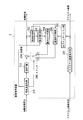
- FIG. 2 is a schematic block diagram of the image encoding device 1 according to the present embodiment.
- the image encoding device 1 includes a distance image input unit 100, a motion vector detection unit 101, a screen storage unit 102, a motion compensation unit 103, a weighted prediction unit 104, a segmentation unit 105, an intra-screen prediction unit 106, an encoding control unit 107,
- the switch 108 includes a subtracting unit 109, a DCT unit 110, an inverse DCT unit 113, an adding unit 114, a variable length coding unit 115, and a texture image coding unit 121.
- the distance image input unit 100 receives a distance image for each frame from the outside of the image encoding device 1 and extracts a block (referred to as a “distance image block”) from the input distance image.
- the pixels constituting the distance image correspond to the pixels constituting the texture image input to the texture image encoding unit 121.
- the distance image input unit 100 outputs the extracted distance image block to the motion vector detection unit 101, the encoding control unit 107, and the subtraction unit 109.
- the distance image block is composed of a predetermined number of pixels (for example, 16 pixels in the horizontal direction ⁇ 16 pixels in the vertical direction).
- the distance image input unit 100 shifts the position of the block from which the distance image block is extracted in the raster scan order so that the blocks do not overlap. That is, the distance image input unit 100 sequentially moves the block from which the distance image block is extracted from the upper left end of the frame to the right by the number of pixels in the horizontal direction of the block. After the right end of the block from which the distance image block is extracted reaches the right end of the frame, the distance image input unit 100 moves the block downward by the number of pixels in the vertical direction and to the left end of the frame. The distance image input unit 100 moves the block from which the distance image block is extracted in this way until it reaches the lower right of the frame.
- the motion vector detection unit 101 receives a distance image block from the distance image input unit 100 and reads a block (reference image block) constituting a reference image from the screen storage unit 102.
- the reference image block includes the same number of horizontal and vertical pixels as the distance image block.
- the motion vector detection unit 101 detects the difference between the coordinates of the input distance image block and the coordinates of the corresponding reference image block as a motion vector.
- the motion vector detection unit 101 detects, for example, ITU-T H.264 in order to detect a motion vector. Although a known method described in the H.264 standard can be used, this point will be described below.
- the motion vector detection unit 101 sets the position where the reference image block is read from the frame of the reference image stored in the screen storage unit 102, one pixel at a time in the horizontal direction or the vertical direction within a preset range from the position of the distance image block. Move.
- the motion vector detection unit 101 uses an index value indicating the similarity and correlation between the signal value for each pixel included in the distance image block and the signal for each pixel included in the read reference image block, for example, SAD (Sum of Absolute). Difference; the sum of absolute differences) is calculated. The smaller the SAD value, the more similar the signal value for each pixel included in the distance image block and the signal for each pixel included in the read reference image block.
- the motion vector detection unit 101 determines a predetermined number (for example, 2) of reference image blocks from those that minimize SAD as reference image blocks corresponding to the extracted distance image blocks.
- the motion vector detection unit 101 calculates a motion vector based on the input coordinates of the distance image block and the coordinates of the determined reference image block.
- the motion vector detection unit 101 outputs a motion vector signal indicating the motion vector calculated for each block to the variable length encoding unit 115, and outputs the read reference image block to the motion compensation unit 103.
- the screen storage unit 102 arranges and stores the reference image block input from the addition unit 114 at the block position in the corresponding frame.
- the image signal of the frame configured by arranging the reference image blocks in this way is the reference image.
- the screen storage unit 102 deletes reference images of past frames that are a preset number (for example, 6) or less.
- the motion compensation unit 103 determines the position of the reference image block input from the motion vector detection unit 101 as the position of each input distance image block. Thereby, the motion compensation unit 103 can compensate the position of the reference image block based on the motion vector detected by the motion vector detection unit 101.
- the motion compensation unit 103 outputs the reference image block whose position has been determined to the weighted prediction unit 104.
- the weighted prediction unit 104 multiplies each of the plurality of reference image blocks input from the motion compensation unit 103 by a weighting coefficient and adds them to generate a weighted prediction image block.
- the weighting factor may be a preset weighting factor or a pattern selected from weighting factor patterns stored in advance in the codebook.
- the weighted prediction unit 104 outputs the generated weighted prediction image block to the encoding control unit 107 and the switch 108.
- the texture image is input to the texture image encoding unit 121.
- the segmentation unit 105 receives the decoded texture image block from the texture image encoding unit 121.
- the decoded texture image block constitutes a decoded texture image so as to indicate the original texture image.
- the decoded texture image block input to the segmentation unit 105 corresponds to the distance image block output from the distance image input unit 100 for each pixel.
- the segmentation unit 105 classifies the segment into segments that are groups of one or a plurality of pixels based on the luminance value for each pixel included in the decoded texture image block.
- the segmentation unit 105 outputs segment information indicating the segment to which the pixel included in each block belongs to the intra-screen prediction unit 106.
- the segmentation unit 105 does not divide the original texture image into segments, but divides the decoded texture image block into segments because the decoding side also optimizes the encoding quality using only the obtained information. is there.
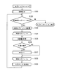
- FIG. 3 is a flowchart showing the process of segmenting into segments in the present embodiment.
- Step S101 For each pixel constituting the block, the segmentation unit 105 sets the segment number (segment number) i to which the pixel belongs to the coordinate of the pixel, and sets a processing flag indicating the presence or absence of processing to 0 (zero). ; Value indicating unprocessed). Further, the segmentation unit 105 initializes a minimum value m of a representative value distance d for each segment, which will be described later. Thereafter, the process proceeds to step S102.
- the decoded texture image is, for example, an RGB signal indicated by using a signal R indicating a red luminance value, a signal G indicating a green luminance value, and a signal B indicating a blue luminance value
- the signal values R, G , B color space vector (R, G, B) indicates a color space for each pixel.
- the decoded texture image is not limited to an RGB signal, but may be a signal based on another color system, such as an HSV signal, a Lab signal, or a YCbCr signal.
- Step S102 The segmentation unit 105 determines whether there is an unprocessed segment with reference to the processing flag in the block. When the segmentation unit 105 determines that there is an unprocessed segment (Y in step S102), the process proceeds to step S103. The segmentation unit 105 determines that there is no unprocessed segment (step S102: N), and ends the segmentation process.
- the segmentation unit 105 changes the segment i to be processed to one of unprocessed segments.
- the segmentation unit 105 changes, for example, in the order of raster scanning. In this order, the segmentation unit 105 sets the upper right end pixel of the previously processed segment as a reference pixel, and sets an unprocessed segment adjacent to the right side as a processing target. If there is no segment to be processed, the reference pixel is sequentially moved to the right one pixel at a time until a segment to be processed is found. If the segment to be processed is not found even if the reference pixel reaches the rightmost pixel of the block, the reference pixel is moved to the pixel one pixel below the leftmost edge of the block.
- the process of moving the reference pixel is repeated until a segment to be processed is found.
- the segmentation unit 105 determines the upper left pixel of the block as the segment to be processed. Thereafter, the process proceeds to step S104.
- the segmentation unit 105 repeats the following steps S105 to S108 for each adjacent segment s adjacent to the segment i to be processed.
- the segmentation unit 105 calculates a distance value d between the representative value of the segment i to be processed and the representative value of the adjacent segment s.
- the representative value for each segment may be an average value of color space vectors for each pixel included in the segment, or one pixel included in the segment (for example, the pixel at the upper left of the segment, the center of gravity of the segment, or the closest point) It may be a color space vector in (pixel). When there is only one pixel included in the segment, the color space vector at that pixel is a representative value.
- the distance value d is an index value indicating the degree of similarity between the representative value of the segment i to be processed and the representative value of the adjacent segment s, for example, the Euclidean distance.
- the distance value d may be any one of a city distance, a Minkowski distance, a Chebyshev distance, and a Mahalanobis distance in addition to the Euclidean distance. Thereafter, the process proceeds to step S106.
- Step S106 The segmentation unit 105 determines whether or not the distance value d is smaller than the minimum value m. When the segmentation unit 105 determines that the distance value d is smaller than the minimum value m (Y in step S106), the process proceeds to step S107. When the segmentation unit 105 determines that the distance value d is equal to or greater than the minimum value m (N in step S106), the process proceeds to step S108. (Step S107) The segmentation unit 105 determines that the adjacent segment s belongs to the target segment i. That is, the segmentation unit 105 determines the adjacent segment s as the target segment i. Further, the segmentation unit 105 replaces the minimum value m with the distance d.
- Step S108 The segmentation unit 105 changes the adjacent segment s adjacent to the target segment i.
- the segmentation unit 105 may perform the same process as the change of the segment i to be processed in step S103.
- the adjacent segment s refers to a segment including pixels in which one of the coordinates in the vertical direction or the horizontal direction is equal to the pixel included in the target segment i and the other coordinate is different by one pixel. .
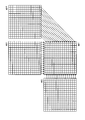
- FIG. 4 is a conceptual diagram showing an example of adjacent segments in the present embodiment.
- the left diagram, the center diagram, and the right diagram in FIG. 4 show, for example, a block composed of 4 pixels in the horizontal direction ⁇ 4 pixels in the vertical direction.
- the segmentation unit 105 determines that the pixel B in the second column from the left in the uppermost row and the pixel A in the second column from the left in the second row from the top are adjacent.
- the segmentation unit 105 determines that the pixel C in the second column from the left in the second row from the top and the pixel D in the third column from the left in the second row from the top are adjacent.
- the segmentation unit 105 determines that the pixel E in the third column from the top left and the pixel F in the second column from the left from the top are not adjacent. That is, the segmentation unit 105 determines that pixels that sandwich at least one side are adjacent to each other. Returning to FIG. 3, if another segment can be found, the segmentation unit 105 sets the found neighboring segment as a new neighboring segment and returns to step S ⁇ b> 105. If another adjacent segment cannot be found, the process proceeds to step S109.
- Step S109 When there is an adjacent segment newly determined as the target segment i, the segmentation unit 105 merges the target segment i and the adjacent segment newly determined as the target segment i (may be referred to as “merge”). . That is, the segmentation unit 105 sets the segment to which each pixel included in the adjacent segment determined as the target segment i belongs as the target segment i. Further, the segmentation unit 105 determines the representative value of the target segment i after merging based on the method described in step S105. Information indicating the segment to which each pixel belongs constitutes the aforementioned segment information. Further, the segmentation unit 105 sets the processing flag of the pixel belonging to the target segment i to 1 (indicating that it has been processed). Thereafter, the process proceeds to step S102.
- the segmentation unit 105 may enlarge the size of each segment by executing the segmentation process shown in FIG. 2 for one reference image block not only once but multiple times. Further, in step S106 of FIG. 3, the segmentation unit 105 further determines whether the distance value d is smaller than a preset distance threshold T, the distance value d is smaller than the minimum value m, and the distance value If it is determined that d is smaller than the preset distance threshold T (Y in step S106), the process may proceed to step S107. Further, the segmentation unit 105 determines that the distance value d is equal to or greater than the minimum value m, or the distance value d is equal to or greater than a preset distance threshold T. If so (N in step S106), the process may proceed to step S108. In this way, the segmentation unit 105 sets the adjacent segment s to the target segment i only when the distance between the representative value of the adjacent segment s and the representative value of the target segment i is within a predetermined value range. Can be merged.
- the segmentation unit 105 may perform processing for merging the adjacent segment s determined to belong to the target segment i to the target segment i described in step S109. In that case, the segmentation unit 105 does not change the representative value of the target segment i even if the adjacent segment s is merged, and performs the determination using the above-described threshold T in step S106. Thereby, the segmentation part 105 can merge a segment, without repeating the segmentation process shown in FIG.
- the intra-screen prediction unit 106 receives segment information for each block from the segmentation unit 105, and reads the reference image block from the screen storage unit 102.
- the reference image block read by the intra-screen prediction unit 106 is a block that has already been encoded and constitutes a reference image of a frame that is currently processed.
- the reference image block read by the in-screen prediction unit 106 is a reference image block adjacent to the left of the block currently being processed and a reference image block adjacent above.
- the intra prediction unit 106 performs intra prediction based on the input segment information and the read reference image block, and generates an intra prediction image block.
- the intra-screen prediction unit 106 is included in an adjacent reference image block as a pixel value candidate (depth value) of a pixel adjacent to (or predetermined adjacent to) a reference image block among processing target blocks (preferably, It is defined as the signal value (depth value) of the closest pixel.
- FIG. 5 is a conceptual diagram illustrating an example of a reference image block and a processing target block according to the present embodiment.
- a lower right block mb1 indicates a processing target block
- a lower left block mb2 and an upper block mb3 indicate reference image blocks that are read out.
- An arrow from each pixel in the bottom row of the block mb3 to the pixel in the corresponding column in the top row of the block mb1 indicates that the in-screen prediction unit 106 sets the depth value of each pixel in the top row of the block mb1 to the depth value of the block mb3.
- the intra-screen prediction unit 106 includes a reference image block on the left side of the processing target block, a reference image block on the upper side of the processing target block, and a reference image block on the upper right side of the processing target block when determining pixel value candidates
- a pixel depth value may be used.
- FIG. 6 is a conceptual diagram illustrating another example of the reference image block and the processing target block according to the present embodiment.
- blocks mb1, mb2, and mb3 are the same as those in FIG.
- the block mb4 on the right side of the upper stage in FIG. 6 shows the read reference image block.
- the part 106 determines the depth value of each pixel from the 2nd row of the rightmost column of the block mb1 to the lowest row as the depth value of each pixel of the mb4 from the 2nd column of the lowest row to the rightmost column.
- the intra-screen prediction unit 106 determines a representative value of the segment based on the pixel value candidate. For example, the in-screen prediction unit 106 may determine an average value of pixel value candidates included in a certain segment as a representative value, or may determine a pixel value candidate in one pixel included in the segment as a representative value. . When a certain segment includes a plurality of identical pixel value candidates, the intra-screen prediction unit 106 may determine the pixel value candidate having the largest number of pixels as the representative value of the segment. Then, the intra-screen prediction unit 106 determines the depth value of each pixel included in the segment as the determined representative value.
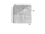
- FIG. 7 is a conceptual diagram illustrating an example of segments and pixel value candidates according to the present embodiment.
- a block mb1 indicates a processing target block.
- the pixel in the shaded portion on the upper left side of the block mb1 indicates the segment S1.
- the arrows directed to the leftmost pixel and the uppermost pixel of the block mb1 indicate that pixel value candidates have been determined for these pixels.
- the intra-screen prediction unit 106 determines the segment S1 based on the pixel value candidates of the pixels in the leftmost first row to eighth row and the pixels in the uppermost row second column to thirteenth column, which are included in the segment S1.
- the representative value of is determined.
- FIG. 8 is a conceptual diagram illustrating other examples of segments and pixel value candidates according to the present embodiment.
- a block mb1 indicates a processing target block.
- a shaded pixel extending from the upper right to the left center of the block mb1 indicates a segment S2.
- the arrows directed to the leftmost pixel and the uppermost pixel of the block mb1 indicate that pixel value candidates have been determined for these pixels.
- the intra prediction unit 106 determines the segment S2 based on the pixel value candidates of the pixels in the leftmost row 9th to 12th row and the pixels in the uppermost row 13th column to 15th column, which are included in the segment S2.
- the representative value of is determined.
- the in-screen prediction unit 106 selects a pixel value candidate for the upper right pixel (hereinafter referred to as the upper right pixel) of the processing target block.
- the depth value of the pixel included in the segment is determined based on the pixel value candidate for the lower left pixel (hereinafter referred to as the lower left pixel) of the block, or both.
- the intra-screen prediction unit 106 determines the depth value of the pixel included in the segment as a pixel value candidate for the upper right pixel or a pixel value candidate for the lower left pixel.
- the intra-screen prediction unit 106 may determine the depth value of the pixels included in the segment as the average value of the pixel value candidates for the upper right pixel and the pixel value candidates for the lower left pixel.
- the in-screen prediction unit 106 includes a value obtained by linearly interpolating each pixel value candidate with a weighting factor corresponding to each distance from the pixel included in the segment to the upper right pixel or the lower left pixel. The pixel depth value may be determined.
- the intra-screen prediction unit 106 determines the depth value of the pixels included in each segment, and generates an intra-screen prediction image block representing the determined depth value for each pixel.
- the distance image block to be encoded is located in the leftmost column of the frame, there is no reference image block adjacent to the encoded left side in the same frame.
- the distance image block to be encoded is located in the uppermost row of the frame, there is no reference image block adjacent on the encoded upper side in the same frame. In such a case, if there is an encoded reference image block in the same frame, the intra-screen prediction unit 106 uses the depth value of the pixel included in the block.
- the intra prediction unit 106 calculates the distance value of the pixels in the second row to the 16th column of the uppermost row in the block.
- the distance values of the pixels from the second row to the sixteenth row in the rightmost column of the reference image block adjacent to the left side are used.
- the intra prediction unit 106 determines the distance between the pixels in the leftmost column and the 16th row of the leftmost column in the block. As the value, the distance value of the pixels from the second column to the sixteenth column of the lowest column of the reference image block adjacent on the upper side is used.
- the intra prediction unit 106 outputs the generated intra prediction image block to the encoding control unit 107 and the switch 108.
- the intra-screen prediction unit 106 may perform intra-screen prediction processing. Can not. Therefore, the in-screen prediction unit 106 does not perform the in-screen prediction process in such a case.
- the encoding control unit 107 receives a distance image block from the distance image input unit 100.
- the encoding control unit 107 receives the weighted prediction image block from the weighted prediction unit 104 and the intra-screen prediction block from the intra-screen prediction unit 106.
- the encoding control unit 107 calculates a weighted prediction residual signal based on the extracted distance image block and the input weighted prediction image block.
- the encoding control unit 107 calculates an intra prediction residual signal based on the extracted distance image block and the input intra prediction image block.
- the encoding control unit 107 based on the calculated weighted prediction residual signal size and the size of the intra prediction prediction signal, for example, the prediction method with the smaller prediction residual signal (either weighted prediction or intra prediction). ).
- the encoding control unit 107 outputs a prediction method signal indicating the determined prediction method to the switch 108 and the variable length encoding unit 115.
- the encoding control unit 107 may determine a prediction method that minimizes the cost calculated using a known cost function for each prediction method.
- the encoding control unit 107 calculates the information amount of the weighted prediction residual signal based on the weighted prediction residual signal, and calculates the weighted prediction cost based on the weighted prediction residual signal and the information amount.
- the encoding control unit 107 calculates the information amount of the intra prediction prediction signal based on the intra prediction residual signal, and calculates the weighted prediction cost based on the weighted prediction residual signal and the information amount.
- the encoding control unit 107 may assign the above-described intra-screen prediction as a signal value of a prediction method signal indicating one of the existing intra-screen prediction modes (for example, the DC mode or the Plane mode).
- the intra prediction unit 106 When the distance image block to be encoded is located at the upper left corner of the frame, the intra prediction unit 106 does not perform the intra prediction process. Therefore, the encoding control unit 107 determines that the prediction method is weighted prediction, and outputs a prediction method signal indicating weighted prediction to the switch 108 and the variable length encoding unit 115.
- the switch 108 includes two contact points a and b.
- a weighted prediction image block is input from the weight prediction unit 104.
- the intra prediction image block is input, and the prediction method signal is input from the encoding control unit 107.
- the switch 108 outputs either the weighted prediction image block or the intra prediction image block input based on the input prediction method signal to the subtraction unit 109 and the addition unit 114 as a prediction image block. That is, when the prediction method signal indicates weighted prediction, the switch 108 outputs the weighted prediction image block as a prediction image block.
- the switch 108 outputs the intra prediction image block as a prediction image block.
- the switch 108 is controlled by the encoding control unit 107.
- the subtractor 109 subtracts the distance values of the pixels constituting the predicted image block input from the switch 108 from the distance values of the pixels constituting the distance image block input from the distance image input unit 100, respectively, and a residual signal block Is generated.
- the subtraction unit 109 outputs the generated residual signal block to the DCT unit 110.
- the DCT unit 110 performs a two-dimensional DCT (Discrete Cosine Transform) on the signal values of the pixels constituting the residual signal block to convert the signal value into a frequency domain signal.
- the DCT unit 110 outputs the converted frequency domain signal to the inverse DCT unit 113 and the variable length coding unit 115.
- the inverse DCT unit 113 performs a two-dimensional inverse DCT (Inverse Discrete Cosine Transform) on the frequency domain signal input from the DCT unit 110 to convert it into a residual signal block.
- the inverse DCT unit 113 outputs the converted residual signal block to the adding unit 114.
- the adder 114 adds the distance values of the pixels forming the prediction signal block input from the switch 108 and the distance values of the pixels forming the residual signal block input from the inverse DCT unit 113, respectively. Is generated.
- the adding unit 114 outputs the generated reference signal block to the screen storage unit 102 for storage.
- the variable length coding unit 115 receives a motion vector signal from the motion vector detection unit 101, a prediction scheme code from the coding control unit 107, and a frequency domain signal from the DCT unit 110.
- the variable length coding unit 115 performs Hadamard transform on the input frequency domain signal, compresses and encodes the signal generated by the conversion so as to have a smaller amount of information, and generates a compressed residual signal.
- the variable length coding unit 115 performs entropy coding.
- the variable length coding unit 115 outputs the compressed residual signal, the input motion vector signal, and the prediction method signal to the outside of the image coding apparatus 1 as a distance image code. If the prediction method is predetermined, this signal may not be included in the distance image signal.
- the texture image encoding unit 121 receives a texture image for each frame from the outside of the image encoding apparatus 1, and a known image encoding method for each block constituting each frame, for example, ITU-T H.264. The encoding is performed using the encoding method described in the H.264 standard.
- the texture image encoding unit 121 outputs the texture image code generated by encoding to the outside of the image encoding device 1.
- the texture image encoding unit 121 outputs the reference signal block generated in the encoding process to the segmentation unit 105 as a decoded texture image block.
- FIG. 9 is a flowchart showing an image encoding process performed by the image encoding device 1 according to the present embodiment.
- the distance image input unit 100 receives a distance image for each frame from the outside of the image encoding device 1, and extracts a distance image block from the input distance image.
- the distance image input unit 100 outputs the extracted distance image block to the motion vector detection unit 101, the encoding control unit 107, and the subtraction unit 109.
- the texture image encoding unit 121 receives a texture image for each frame from the outside of the image encoding device 1 and encodes each block constituting each frame using a known image encoding method.
- the texture image encoding unit 121 outputs the texture image code generated by encoding to the outside of the image encoding device 1.
- the texture image encoding unit 121 outputs the reference signal block generated in the encoding process to the segmentation unit 105 as a decoded texture image block. Thereafter, the process proceeds to step S202.
- Step S202 Steps S203 to S215 are executed for each block in the frame.
- Step S ⁇ b> 203 The motion vector detection unit 101 receives a distance image block from the distance image input unit 100 and reads a reference image block from the screen storage unit 102.
- the motion vector detection unit 101 determines a predetermined number of reference image blocks from the one that minimizes the index value with the distance image block input from the read reference image block.
- the motion vector detection unit 101 detects a difference between the determined coordinates of the reference image block and the input coordinates of the distance image block as a motion vector.
- the motion vector detection unit 101 outputs a motion vector signal indicating the detected motion vector to the variable length coding unit 115, and outputs the read reference image block to the motion compensation unit 103. Thereafter, the process proceeds to step S204.
- Step S204 The motion compensation unit 103 determines the position of the reference image block input from the motion vector detection unit 101 as the position of each input distance image block.
- the motion compensation unit 103 outputs the reference image block whose position has been determined to the weighted prediction unit 104. Thereafter, the process proceeds to step S205.
- Step S205 The weighted prediction unit 104 multiplies each of the reference image blocks input from the motion compensation unit 103 by a weighting coefficient and adds them to generate a weighted prediction image block.
- the weighted prediction unit 104 outputs the generated weighted prediction image block to the encoding control unit 107 and the switch 108. Thereafter, the process proceeds to step S206.
- Step S206 The segmentation unit 105 receives the decoded texture image block from the texture image encoding unit 121. Based on the luminance value for each pixel included in the decoded texture image block, the segmentation unit 105 classifies the segment into segments that are groups of the pixel. The segmentation unit 105 outputs segment information indicating the segment to which the pixel included in each block belongs to the intra-screen prediction unit 106.
- the process shown in FIG. 3 is performed as the process in which the segmentation unit 105 divides into segments. Thereafter, the process proceeds to step S207.
- Step S207 The intra-screen prediction unit 106 receives the segment information for each block from the segmentation unit 105, and reads the reference image block from the screen storage unit 102.
- the intra-screen prediction unit 106 performs intra-screen prediction based on the input segment information and the read reference image block, and generates an intra-screen prediction image block.
- the intra prediction unit 106 outputs the generated intra prediction image block to the encoding control unit 107 and the switch 108. Thereafter, the process proceeds to step S208.
- the encoding control unit 107 receives a distance image block from the distance image input unit 100.
- the encoding control unit 107 receives the weighted prediction image block from the weighted prediction unit 104 and the intra-screen prediction block from the intra-screen prediction unit 106.
- the encoding control unit 107 calculates a weighted prediction residual signal based on the extracted distance image block and the input weighted prediction image block.
- the encoding control unit 107 calculates an intra prediction residual signal based on the extracted distance image block and the input intra prediction image block.
- the encoding control unit 107 determines a prediction method based on the calculated weighted prediction residual signal magnitude and the intra-screen prediction residual signal magnitude.
- the encoding control unit 107 outputs a prediction method signal indicating the determined prediction method to the switch 108 and the variable length encoding unit 115.
- the switch 108 receives a weighted prediction image block from the weighted prediction unit 104, receives an intra-screen prediction image block from the intra-screen prediction unit 106, and receives a prediction method signal from the encoding control unit 107.
- the switch 108 outputs either the weighted prediction image block or the intra prediction image block input based on the input prediction method signal to the subtraction unit 109 and the addition unit 114 as a prediction image block. Thereafter, the process proceeds to step S209.
- Step S209 The subtraction unit 109 subtracts the distance values of the pixels constituting the prediction image block input from the switch 108 from the distance values of the pixels constituting the distance image block input from the distance image input unit 100, respectively. Generate a residual signal block. The subtraction unit 109 outputs the generated residual signal block to the DCT unit 110. Thereafter, the process proceeds to step S210.
- Step S ⁇ b> 210) The DCT unit 110 performs two-dimensional DCT (Discrete Cosine Transform) on the signal values of the pixels constituting the residual signal block to convert them into frequency domain signals.
- the DCT unit 110 outputs the converted frequency domain signal to the inverse DCT unit 113 and the variable length coding unit 115. Then, it progresses to step S211.
- DCT Discrete Cosine Transform
- Step S211 The inverse DCT unit 113 performs a two-dimensional inverse DCT on the frequency domain signal input from the DCT unit 110 to convert it into a residual signal block.
- the inverse DCT unit 113 outputs the converted residual signal block to the adding unit 114.
- step S212 The adding unit 114 adds the distance value of the pixels forming the prediction signal block input from the switch 108 and the distance value of the pixels forming the residual signal block input from the inverse DCT unit 113, respectively.
- a reference signal block is generated.
- the adding unit 114 outputs the generated reference signal block to the screen storage unit 102. Thereafter, the process proceeds to step S213.
- Step S213 The screen storage unit 102 arranges and stores the reference image block input from the addition unit 114 at the position of the block in the corresponding frame. Thereafter, the process proceeds to step S214.
- Step S214 The variable length encoding unit 115 performs Hadamard transform on the frequency domain signal input from the DCT unit 110, and compresses and encodes the signal generated by the conversion to generate a compression residual signal.
- the variable length encoding unit 115 uses the generated compressed residual signal, the motion vector signal input from the motion vector detection unit 101, and the prediction method signal input from the encoding control unit 107 as a distance image code. To the outside. Thereafter, the process proceeds to step S215.
- Step S215) When the processing has not been completed for all the blocks in the frame, the distance image input unit 100 shifts the distance image blocks to be extracted from the input distance image, for example, in the order of raster scanning. Thereafter, the process returns to step S203. When the processing is completed for all the blocks in the frame, the distance image input unit 100 ends the processing for that frame.
- FIG. 10 is a schematic diagram illustrating a configuration of the image decoding device 2 according to the present embodiment.
- the image decoding device 2 includes a screen storage unit 202, a motion compensation unit 203, a weighted prediction unit 204, a segmentation unit 205, an intra-screen prediction unit 206, a switch 208, an inverse DCT unit 213, an addition unit 214, a variable length decoding unit 215, and a texture.
- An image decoding unit 221 is included.
- the screen storage unit 202 arranges and stores the reference image block input from the addition unit 214 at the position of the block in the corresponding frame. Note that the screen storage unit 102 deletes reference images of past frames that are a preset number (for example, 6) or less.
- the motion compensation unit 203 receives the motion vector signal from the variable length decoding unit 215. The motion compensation unit 203 extracts the reference image block having the coordinates indicated by the motion vector signal from the reference image stored in the screen storage unit 202. The motion compensation unit 203 outputs the extracted reference image block to the weighted prediction unit 204.
- the weighted prediction unit 204 multiplies each of the reference image blocks input from the motion compensation unit 203 by a weighting coefficient and adds them to generate a weighted prediction image block.
- the weighting factor may be a preset weighting factor or a pattern selected from weighting factor patterns stored in advance in the codebook.
- the weighted prediction unit 204 outputs the generated weighted prediction image block to the switch 208.
- the segmentation unit 205 receives the decoded texture image block constituting the texture image decoded from the texture image decoding unit 221.
- the input decoded texture image block corresponds to the distance image code input to the variable length decoding unit 215.
- the segmentation unit 205 classifies the segment into a group of pixels based on the luminance value for each pixel included in the decoded texture image block.
- the segmentation unit 205 performs the process shown in FIG. 3 in order to segment the decoded texture image block into segments.
- the segmentation unit 205 outputs segment information indicating the segment to which the pixels included in each block belong to the in-screen prediction unit 206.
- the intra-screen prediction unit 206 receives segment information for each block from the segmentation unit 205 and reads the reference image block from the screen storage unit 202.
- the reference image block read by the in-screen prediction unit 206 is a block that has already been decoded and constitutes a reference image of a frame that is currently processed.
- the reference image block read by the in-screen prediction unit 206 is a reference image block adjacent to the left of the block currently being processed and a reference image block adjacent above.
- the intra-screen prediction unit 206 performs intra-screen prediction based on the input segment information and the read reference image block, and generates an intra-screen prediction image block.
- the process of generating the intra-screen prediction image block by the intra-screen prediction unit 206 may be the same as the process performed by the intra-screen prediction unit 106.
- the intra-screen prediction unit 206 outputs the generated intra-screen prediction image block to the switch 208.
- the switch 208 includes two contact points a and b.
- a weighted prediction image block is input from the weight prediction unit 204.
- the intra prediction image block is input, and the prediction method signal is input from the variable length decoding unit 215.
- the switch 208 outputs either the weighted prediction image block or the intra prediction image block input based on the input prediction method signal to the adding unit 214 as a prediction image block. That is, when the prediction method signal indicates weighted prediction, the switch 208 outputs the weighted prediction image block as a prediction image block.
- the switch 208 When the prediction method signal indicates intra prediction, the switch 208 outputs the intra prediction image block as a prediction image block.
- the variable length decoding unit 215 receives a distance image code from the outside of the image decoding device 2, and indicates a compressed residual signal indicating a residual signal, a motion vector signal indicating a motion vector, and a prediction method from the input distance image code. Extract a prediction scheme signal. The variable length decoding unit 215 decodes the extracted compressed residual signal. This decoding method is a process opposite to the compression coding performed by the variable length coding unit 115 and is a process of generating an original signal having a larger amount of information, for example, entropy decoding. The variable length decoding unit 215 generates a frequency domain signal by performing Hadamard transform on the signal generated by decoding.
- This Hadamard transform is an inverse transform of the Hadamard transform performed by the variable length coding unit 115 and is a process of generating the original frequency domain signal.
- the variable length decoding unit 215 outputs the generated frequency domain signal to the inverse DCT unit 213.
- the variable length decoding unit 215 outputs the extracted motion vector signal to the motion compensation unit 203 and outputs the extracted prediction method signal to the switch 208.
- the inverse DCT unit 213 performs two-dimensional inverse DCT on the frequency domain signal input from the variable length decoding unit 215 to convert the signal into a residual signal block.
- the inverse DCT unit 213 outputs the converted residual signal block to the adding unit 214.
- the adder 214 adds the distance values of the pixels forming the prediction signal block input from the switch 208 and the distance values of the pixels forming the residual signal block input from the inverse DCT unit 213, respectively. Is generated.
- the adding unit 214 outputs the generated reference signal block to the outside of the screen storage unit 202 and the image decoding device 2.
- the reference signal block output to the outside of the image decoding device 2 is a distance image block that constitutes a decoded distance image.
- the texture image decoding unit 221 receives a texture image code from the outside of the image decoding apparatus 2 for each block, and a known image decoding method for each block, for example, ITU-T H.264.
- the decoded texture image block is generated by decoding using the decoding method described in the H.264 standard.
- the texture image decoding unit 221 outputs the generated decoded texture image block to the outside of the segmentation unit 205 and the image decoding device 2.
- the decoded texture image block output to the outside of the image decoding device 2 is an image block constituting the decoded texture image.
- FIG. 11 is a flowchart showing an image decoding process performed by the image decoding apparatus 2 according to this embodiment.
- the variable length decoding unit 215 receives a distance image code from the outside of the image decoding device 2, and from the input distance image code, a compressed residual signal indicating a residual signal, a motion vector signal indicating a motion vector, and A prediction method signal indicating the prediction method is extracted.
- the variable length decoding unit 215 decodes the extracted compressed residual signal, and generates a frequency domain signal by Hadamard transforming the signal generated by the decoding.
- the variable length decoding unit 215 outputs the generated frequency domain signal to the inverse DCT unit 213.
- the variable length decoding unit 215 outputs the extracted motion vector signal to the motion compensation unit 203 and outputs the extracted prediction method signal to the switch 208.
- the texture image decoding unit 221 receives a texture image code for each block from the outside of the image decoding device 2 and decodes each block using a known image decoding method to generate a decoded texture image block.
- the texture image decoding unit 221 outputs the generated decoded texture image block to the outside of the segmentation unit 205 and the image decoding device 2. Thereafter, the process proceeds to step S302.
- Step S302 Steps S303 to S309 are executed for each block in the frame.
- the switch 208 determines whether the prediction method signal input from the variable length decoding unit 215 indicates intra prediction or weighted prediction. When the switch 208 determines that the prediction method signal indicates intra prediction (Y in step S303), the process proceeds to step S304. In addition, the weighted prediction image block generated in step S305 described later is output to the addition unit 214 as a prediction image block. When the switch 208 determines that the prediction method signal indicates weighted prediction (N in step S303), the process proceeds to step S306. In addition, the intra prediction image block generated in step S307 described later is output to the addition unit 214 as a prediction image block.
- Step S ⁇ b> 304 The segmentation unit 205 divides the segment into segments that are groups of pixels based on the luminance value of each pixel included in the decoded texture image block input from the texture image decoding unit 221.
- the segmentation unit 205 outputs segment information indicating the segment to which the pixels included in each block belong to the in-screen prediction unit 206.
- the process shown in FIG. 3 is performed as the process in which the segmentation unit 205 classifies the segment. Thereafter, the process proceeds to step S305.
- Step S305 The intra-screen prediction unit 206 receives the segment information for each block from the segmentation unit 205, and reads the reference image block from the screen storage unit 202.
- the intra-screen prediction unit 206 performs intra-screen prediction based on the input segment information and the read reference image block, and generates an intra-screen prediction image block.
- the process of generating the intra-screen prediction image block by the intra-screen prediction unit 206 may be the same as the process performed by the intra-screen prediction unit 106.
- the intra-screen prediction unit 206 outputs the generated intra-screen prediction image block to the switch 208. Thereafter, the process proceeds to step S308.
- Step S306 The motion compensation unit 203 extracts a reference image block having coordinates indicated by the motion vector signal input from the variable length decoding unit 215, from the reference image stored in the screen storage unit 202.
- the motion compensation unit 203 outputs the extracted reference image block to the weighted prediction unit 204. Thereafter, the process proceeds to step S307.
- Step S307 The weighted prediction unit 204 multiplies each of the reference image blocks input from the motion compensation unit 203 by a weighting coefficient and adds them to generate a weighted predicted image block.
- the weighted prediction unit 204 outputs the generated weighted prediction image block to the switch 208. Thereafter, the process proceeds to step S308.
- Step S308 The inverse DCT unit 213 performs two-dimensional inverse DCT on the frequency domain signal input from the variable length decoding unit 215 to convert it into a residual signal block.
- the inverse DCT unit 213 outputs the converted residual signal block to the adding unit 214.
- step S309 The adding unit 214 adds the distance value of the pixels constituting the prediction signal block input from the switch 208 and the distance value of the pixels constituting the residual signal block input from the inverse DCT unit 213, respectively.
- a reference signal block is generated.
- the adding unit 214 outputs the generated reference signal block to the outside of the screen storage unit 202 and the image decoding device 2. Thereafter, the process proceeds to step S310.
- the size of the texture image block, the distance image block, the predicted image block, and the reference image block has been described as 16 pixels in the horizontal direction ⁇ 16 pixels in the vertical direction.
- This size is, for example, horizontal 8 pixels ⁇ vertical 8 pixels, horizontal 4 pixels ⁇ vertical 4 pixels, horizontal 32 pixels ⁇ vertical 32 pixels, horizontal 16 pixels ⁇ vertical 8 pixels, horizontal 8 Pixel ⁇ vertical 16 pixels, horizontal 8 pixels ⁇ vertical 4 pixels, horizontal 4 pixels ⁇ vertical 8 pixels, horizontal 32 pixels ⁇ vertical 16 pixels, horizontal 16 pixels ⁇ vertical 32 pixels But you can.
- the image in an image encoding apparatus that encodes a distance image including a depth value for each pixel representing a distance from a viewpoint to a subject, for each block, the image includes a luminance value for each pixel of the subject.
- a block of a texture image is divided into segments composed of the pixels based on a luminance value, and a depth value for each of the divided segments included in one block of a distance image is already encoded and is a block adjacent to the one block Is generated based on the depth value of the pixels included in the image, and a predicted image including the determined depth value for each segment is generated for each block.
- a texture image block including a luminance value for each pixel of the subject Are segmented into segments consisting of the pixels based on the luminance value, and the depth value of each segment segment included in one block of the distance image is already decoded and included in a block adjacent to one block Based on the depth value of the pixel, a predicted image including the determined depth value for each segment is generated for each block.
- the portion representing the same subject in the texture image tends to have a relatively poor color spatial change, but considering the correlation between the texture image and the distance image corresponding to this, the depth of the portion also represents that portion. There is little spatial change in value. Therefore, based on the signal value indicating the color of each pixel included in the texture image, it is expected that the depth value in the segment dividing the processing target block is the same. Therefore, when this embodiment is provided with the above-described configuration, an intra-screen prediction image block can be generated with high accuracy, and thus a distance image can be encoded or decoded.
- the distance image block can be encoded or decoded based on the texture image block using the above-described intra-screen prediction method.
- the amount of information of at most 1 bit increases only for each block. Therefore, according to the present embodiment, not only can the distance image be encoded or decoded with high accuracy, but also an increase in the amount of information can be suppressed.
- a part of the image encoding device 1 or the image decoding device 2 in the above-described embodiment for example, the distance image input unit 100, the motion vector detection unit 101, the motion compensation units 103 and 203, the weighted prediction units 104 and 204, the segmentation.
- Units 105 and 205, intra prediction units 106 and 206, coding control unit 107, switches 108 and 208, subtraction unit 109, DCT unit 110, inverse DCT units 113 and 213, addition units 114 and 214, variable length coding unit 115 and the variable length decoding unit 215 may be realized by a computer.
- the program for realizing the control function may be recorded on a computer-readable recording medium, and the program recorded on the recording medium may be read by a computer system and executed.
- the “computer system” is a computer system built in the image encoding device 1 or the image decoding device 2 and includes an OS and hardware such as peripheral devices.
- the “computer-readable recording medium” refers to a storage device such as a flexible medium, a magneto-optical disk, a portable medium such as a ROM or a CD-ROM, and a hard disk incorporated in a computer system.
- the “computer-readable recording medium” is a medium that dynamically holds a program for a short time, such as a communication line when transmitting a program via a network such as the Internet or a communication line such as a telephone line,
- a volatile memory inside a computer system serving as a server or a client may be included and a program that holds a program for a certain period of time.
- the program may be a program for realizing a part of the functions described above, and may be a program capable of realizing the functions described above in combination with a program already recorded in a computer system.
- LSI Large Scale Integration
- Each functional block of the image encoding device 1 or the image decoding device 2 may be individually made into a processor, or a part or all of them may be integrated into a processor.
- the method of circuit integration is not limited to LSI, and may be realized by a dedicated circuit or a general-purpose processor. Further, in the case where an integrated circuit technology that replaces LSI appears due to progress in semiconductor technology, an integrated circuit based on the technology may be used.
- the image encoding device, the image encoding method, the image encoding program, the image decoding device, the image decoding method, and the image decoding program according to the present invention compress the information amount of the image signal representing a three-dimensional image. For example, it is suitable for storage and transmission of image content.
Landscapes
- Engineering & Computer Science (AREA)
- Multimedia (AREA)
- Signal Processing (AREA)
- Physics & Mathematics (AREA)
- General Physics & Mathematics (AREA)
- Theoretical Computer Science (AREA)
- Compression Or Coding Systems Of Tv Signals (AREA)
- Testing, Inspecting, Measuring Of Stereoscopic Televisions And Televisions (AREA)
Abstract
Description
本願は、2011年4月25日に、日本に出願された特願2011-097176号に基づき優先権を主張し、その内容をここに援用する。
図1は、本発明の実施形態に係る3次元画像撮影システムを示す概略図である。この画像撮影システムは、撮影装置31、撮影装置32、画像前置処理部41及び画像符号化装置1を含んで構成される。
撮影装置31及び撮影装置32は、互いに異なる位置(視点)に設置され同一の視野に含まれる被写体の画像を予め定めた時間間隔で撮影する。撮影装置31及び撮影装置32は、撮影した画像をそれぞれ画像前置処理部41に出力する。
画像前置処理部41は、テクスチャ画像と生成した距離画像を画像符号化装置1に出力する。
画像符号化装置1は、距離画像入力部100、動きベクトル検出部101、画面記憶部102、動き補償部103、重み付け予測部104、セグメンテーション部105、画面内予測部106、符号化制御部107、スイッチ108、減算部109、DCT部110、逆DCT部113、加算部114、可変長符号化部115及びテクスチャ画像符号化部121を含んで構成される。
距離画像ブロックは、予め定めた数の画素(例えば、水平方向16画素×垂直方向16画素)からなる。
参照画像ブロックは、距離画像ブロックと同一個数の水平方向及び垂直方向の画素からなる。動きベクトル検出部101は、入力された距離画像ブロックの座標と対応する参照画像ブロックとの座標との差分を動きベクトルとして検出する。動きベクトル検出部101は、動きベクトルを検出するために、例えばITU-T H.264規格書に記載されている公知の方法を用いることができるが、以下のこの点の説明を行う。
動きベクトル検出部101は、ブロック毎に算出した動きベクトルを示す動きベクトル信号を可変長符号化部115に出力し、読み出した参照画像ブロックを動き補償部103に出力する。
動き補償部103は、動きベクトル検出部101から入力された参照画像ブロックの位置を、それぞれ入力された距離画像ブロックの位置として定める。これにより、動き補償部103は、その参照画像ブロックの位置を、動きベクトル検出部101が検出した動きベクトルに基づいて補償することができる。動き補償部103は、位置を定めた参照画像ブロックを重み付け予測部104に出力する。
セグメンテーション部105は、各ブロックに含まれる画素が属するセグメントを示すセグメント情報を画面内予測部106に出力する。
セグメンテーション部105が、元のテクスチャ画像をセグメントに区分するのではなく、復号テクスチャ画像ブロックをセグメントに区分するのは、復号側でも、得られる情報のみを用いて符号化品質を最適化するためである。
図3は、本実施形態におけるセグメントに区分する処理を示すフローチャートである。
(ステップS101)セグメンテーション部105は、ブロックを構成する画素毎に、その画素が属するセグメントの番号(セグメント番号)iを、その画素の座標とし、かつ、処理の有無を示す処理フラグを0(ゼロ;未処理を示す値)と初期設定する。また、セグメンテーション部105は、後述するセグメント毎の代表値間距離dの最小値mを初期設定する。その後、ステップS102に進む。
なお、処理済のセグメントが存在しない初期において、セグメンテーション部105は、ブロックの左上端の画素を処理対象のセグメントと定める。その後、ステップS104に進む。
(ステップS105)セグメンテーション部105は、処理対象のセグメントiの代表値と隣接セグメントsの代表値との間の距離値dを算出する。
セグメント毎の代表値は、セグメントに含まれる画素毎の色空間ベクトルの平均値でもよいし、そのセグメントに含まれる1つの画素(例えば、セグメントの最も左上にある画素、セグメントの重心又は最も近接する画素)における色空間ベクトルでもよい。なお、セグメントに含まれる画素が1個しかない場合には、その画素における色空間ベクトルが代表値となる。
距離値dは、処理対象のセグメントiの代表値と隣接セグメントsの代表値との間の類似度を示す指標値、例えばユークリッド距離である。本実施形態では、距離値dは、ユークリッド距離以外にも、市街地距離、ミンコフスキー距離、チェビシェフ距離、マハラノビス距離のいずれでもよい。その後、ステップS106に進む。
(ステップS107)セグメンテーション部105は、隣接セグメントsが対象セグメントiに属すると判断する。即ち、セグメンテーション部105は、隣接セグメントsを対象セグメントiと決定する。また、セグメンテーション部105は、最小値mを距離dで置き換える。その後、ステップS108に進む。
(ステップS108)セグメンテーション部105は、対象セグメントiに隣接する隣接セグメントsを変更する。セグメンテーション部105が、隣接セグメントsを変更する処理において、ステップS103における処理対象のセグメントiの変更と同様な処理を行ってもよい。但し、本実施形態では、隣接セグメントsとは、対象セグメントiに含まれる画素と垂直方向又は水平方向の何れか一方の座標が等しく、その他方の座標が1画素分異なる画素を含むセグメントを指す。
図4の左図、中央図、及び右図は、一例として、水平方向4画素×垂直方向4画素からなるブロックを示す。図4の左図において、セグメンテーション部105は、最上行左から2列目の画素Bと、上から2行目左から2列目の画素Aは隣接すると判断する。図3の中央図において、セグメンテーション部105は、上から2行目左から2列目の画素Cと、上から2行目左から3列目の画素Dは隣接すると判断する。図3の右図において、セグメンテーション部105は、最上行左から3列目の画素Eと、上から2行目左から2列目の画素Fは隣接しないと判断する。即ち、セグメンテーション部105は、少なくとも一辺を挟んでいる画素同士を隣接していると判断する。
図3に戻り、セグメンテーション部105は、他の隣接セグメントを発見できた場合には、発見した隣接セグメントを新たな隣接セグメントとして、ステップS105に戻る。他の隣接セグメントを発見できなかった場合には、ステップS109に進む。
また、セグメンテーション部105は、図3のステップS106において、さらに距離値dが予め設定した距離の閾値Tよりも小さいか否か判断し、距離値dが最小値mよりも小さく、かつ、距離値dが予め設定した距離の閾値Tよりも小さいと判断した場合(ステップS106 Y)、ステップS107に進むようにしてもよい。また、セグメンテーション部105は、距離値dが最小値mと等しい、もしくは最小値mよりも大きい、又は、距離値dが予め設定した距離の閾値Tと等しい、もしくは閾値Tよりも大きいと判断した場合(ステップS106 N)、ステップS108に進むようにしてもよい。
このようにすることで、隣接セグメントsの代表値と対象セグメントiの代表値の間の距離が所定の値の範囲内にある場合に限り、セグメンテーション部105は、隣接セグメントsを対象セグメントiに併合することができる。
図5は、本実施形態に係る参照画像ブロックと処理対象ブロックの一例を示す概念図である。
図5において、下段の右側のブロックmb1は処理対象ブロックを示し、下段の左側のブロックmb2及び上段のブロックmb3は、各々読み出された参照画像ブロックを示す。
図5のブロックmb3の最下行の各画素からブロックmb1の最上行の対応する列の画素への矢印は、画面内予測部106がブロックmb1の最上行の各画素の深度値をブロックmb3の最下行の対応する画素の深度値と定めることを示す。図5のブロックmb2の最右列の上から2行目から最下行までの各画素からブロックmb1の最左列の対応する行の画素への矢印は、画面内予測部106がブロックmb1の最左列の各画素の深度値をブロックmb2の最右列の対応する画素の深度値と定めることを示す。
なお、ブロックmb1の左上端の画素の深度値を、ブロックmb2の右上端の画素の深度値と定めてもよい。
図6は、本実施形態に係る参照画像ブロックと処理対象ブロックのその他の例を示す概念図である。
図6において、ブロックmb1、mb2及びmb3は図5と同様である。図6の上段右側のブロックmb4は、読み出された参照画像ブロックを示す。図6のブロックmb4の最下行第2列から最右列までの各画素から、各々対応する画素としてブロックmb1の最右列第2行から最下行までの各画素への矢印は、画面内予測部106が、ブロックmb1の最右列第2行から最下行までの各画素の深度値を各々mb4の最下行第2列から最右列までの各画素の深度値と定めることを示す。
例えば、画面内予測部106は、あるセグメントに含まれる画素値候補の平均値を代表値と定めてもよいし、そのセグメントに含まれる一つの画素における画素値候補を代表値と定めてもよい。あるセグメントが複数の同一の画素値候補を含む場合には、画面内予測部106は、画素数が最も多い画素値候補をそのセグメントの代表値と定めてもよい。
そして、画面内予測部106は、そのセグメントに含まれる各画素の深度値を、その定めた代表値に定める。
図7においてブロックmb1は、処理対象ブロックを示す。ブロックmb1の左上側の網掛け部分の画素は、セグメントS1を示す。ブロックmb1の最左段及び最上行の各画素に向かう矢印は、それらの画素について画素値候補が定められたことを示す。ここで、画面内予測部106は、セグメントS1に含まれる、最左段第1行-第8行の画素及び最上行第2列-第13列の画素の画素値候補に基づいて、セグメントS1の代表値を定める。
図8は、本実施形態に係るセグメントと画素値候補のその他の例を示す概念図である。
図8においてブロックmb1は、処理対象ブロックを示す。ブロックmb1の右上から左中央に広がる網掛け部分の画素は、セグメントS2を示す。ブロックmb1の最左段及び最上行の各画素に向かう矢印は、それらの画素について画素値候補が定められたことを示す。ここで、画面内予測部106は、セグメントS2に含まれる、最左段第9行-第12行の画素及び最上行第13列-第15列の画素の画素値候補に基づいて、セグメントS2の代表値を定める。
例えば、画面内予測部106は、そのセグメントに含まれる画素の深度値を、右上端画素に対する画素値候補又は左下端画素に対する画素値候補と定める。または、画面内予測部106は、そのセグメントに含まれる画素の深度値を、右上端画素に対する画素値候補と左下端画素に対する画素値候補の平均値と定めてもよい。または、画面内予測部106は、そのセグメントに含まれる画素と右上端画素又は左下端画素までの各距離に応じた重み係数で、それぞれの画素値候補を線形補間した値を、そのセグメントに含まれる画素の深度値と定めてもよい。
なお、符号化対象の距離画像ブロックが、フレームの最左列に位置している場合には、同一フレーム内の符号化済みの左側に隣接する参照画像ブロックが存在しない。また、符号化対象の距離画像ブロックが、フレームの最上行に位置している場合には、同一フレーム内の符号化済みの上側に隣接する参照画像ブロックが存在しない。このような場合には、画面内予測部106は、同一フレーム内の符号化済みの参照画像ブロックがあれば、そのブロックに含まれる画素の深度値を用いる。
なお、符号化対象の距離画像ブロックが、フレームの左上端に位置している場合には、同一フレームの参照画像ブロックが存在しないため、画面内予測部106は、画面内予測処理を行うことができない。従って、画面内予測部106は、そのような場合には、画面内予測処理を行わない。
符号化制御部107は、抽出した距離画像ブロックと入力された重み付け予測画像ブロックに基づき重み付け予測残差信号を算出する。符号化制御部107は、抽出した距離画像ブロックと入力された画面内予測画像ブロックに基づき画面内予測残差信号を算出する。
符号化制御部107は、算出した重み付け予測残差信号の大きさと画面内予測残差信号の大きさに基づき、例えば予測残差信号が小さいほうの予測方式(重み付け予測又は画面内予測のいずれか)を決定する。符号化制御部107は、決定した予測方式を示す予測方式信号をスイッチ108及び可変長符号化部115に出力する。
また、符号化制御部107は、既存の画面内予測モード(例えば、DCモード又はPlaneモード)の1つを示す予測方式信号の信号値として上述の画面内予測を割り当ててもよい。
即ち、予測方式信号が重み付け予測を示す場合には、スイッチ108は、重み付け予測画像ブロックを予測画像ブロックとして出力する。予測方式信号が画面内予測を示す場合には、スイッチ108は、画面内予測画像ブロックを予測画像ブロックとして出力する。なお、スイッチ108は、符号化制御部107により制御される。
DCT部110は、残差信号ブロックを構成する画素の信号値に2次元DCT(Discrete Cosine Transform;離散コサイン変換)を行って周波数領域信号に変換する。DCT部110は、変換した周波数領域信号を逆DCT部113及び可変長符号化部115に出力する。
加算部114は、スイッチ108から入力された予測信号ブロックを構成する画素の距離値と逆DCT部113から入力された残差信号ブロックを構成する画素の距離値を各々加算して、参照信号ブロックを生成する。加算部114は、生成した参照信号ブロックを画面記憶部102に出力して、記憶させる。
図9は、本実施形態に係る画像符号化装置1が行う画像符号化処理を示すフローチャートである。
(ステップS201)距離画像入力部100は、画像符号化装置1の外部から距離画像をフレーム毎に入力され、入力された距離画像から距離画像ブロックを抽出する。距離画像入力部100は、抽出した距離画像ブロックを動きベクトル検出部101、符号化制御部107及び減算部109に出力する。
テクスチャ画像符号化部121は、画像符号化装置1の外部からテクスチャ画像をフレーム毎に入力され、各フレームを構成するブロック毎に公知の画像符号化方法を用いて符号化する。テクスチャ画像符号化部121は、符号化によって生成したテクスチャ画像符号を画像符号化装置1の外部に出力する。テクスチャ画像符号化部121は、符号化の過程で生成した参照信号ブロックを復号テクスチャ画像ブロックとしてセグメンテーション部105に出力する。
その後、ステップS202に進む。
(ステップS203)動きベクトル検出部101は、距離画像入力部100から距離画像ブロックが入力され、画面記憶部102から参照画像ブロックを読み出す。動きベクトル検出部101は、読み出した参照画像ブロックから入力された距離画像ブロックとの指標値を最小にするものから予め定めた個数の参照画像ブロックを決定する。動きベクトル検出部101は、決定した参照画像ブロックの座標と入力された距離画像ブロックの座標との差分を動きベクトルとして検出する。
動きベクトル検出部101は、検出した動きベクトルを示す動きベクトル信号を可変長符号化部115に出力し、読み出した参照画像ブロックを動き補償部103に出力する。その後、ステップS204に進む。
(ステップS205)重み付け予測部104は、動き補償部103から入力された参照画像ブロックに各々重み付け係数を乗じて加算して、重み付け予測画像ブロックを生成する。重み付け予測部104は、生成した重み付け予測画像ブロックを符号化制御部107及びスイッチ108に出力する。その後、ステップS206に進む。
画面内予測部106は、入力されたセグメント情報と読み出した参照画像ブロックに基づき画面内予測を行い、画面内予測画像ブロックを生成する。画面内予測部106は、生成した画面内予測画像ブロックを符号化制御部107及びスイッチ108に出力する。その後、ステップS208に進む。
符号化制御部107は、抽出した距離画像ブロックと入力された重み付け予測画像ブロックに基づき重み付け予測残差信号を算出する。符号化制御部107は、抽出した距離画像ブロックと入力された画面内予測画像ブロックに基づき画面内予測残差信号を算出する。
符号化制御部107は、算出した重み付け予測残差信号の大きさと画面内予測残差信号の大きさに基づき、予測方式を決定する。符号化制御部107は、決定した予測方式を示す予測方式信号をスイッチ108及び可変長符号化部115に出力する。
スイッチ108は、重み付け予測部104から重み付け予測画像ブロックを入力され、画面内予測部106から画面内予測画像ブロックを入力され、符号化制御部107から予測方式信号を入力される。スイッチ108は、入力された予測方式信号に基づき入力された重み付け予測画像ブロックと画面内予測画像ブロックのいずれかを予測画像ブロックとして減算部109及び加算部114に出力する。その後、ステップS209に進む。
(ステップS210)DCT部110は、残差信号ブロックを構成する画素の信号値に2次元DCT(Discrete Cosine Transform;離散コサイン変換)を行って周波数領域信号に変換する。DCT部110は、変換した周波数領域信号を逆DCT部113及び可変長符号化部115に出力する。その後、ステップS211に進む。
(ステップS212)加算部114は、スイッチ108から入力された予測信号ブロックを構成する画素の距離値と逆DCT部113から入力された残差信号ブロックを構成する画素の距離値を各々加算して、参照信号ブロックを生成する。加算部114は、生成した参照信号ブロックを画面記憶部102に出力する。その後、ステップS213に進む。
(ステップS214)可変長符号化部115は、DCT部110から入力された周波数領域信号をアダマール変換し、変換して生成された信号を圧縮符号化して圧縮残差信号を生成する。可変長符号化部115は、生成した圧縮残差信号、動きベクトル検出部101から入力された動きベクトル信号及び符号化制御部107から入力された予測方式信号を距離画像符号として画像符号化装置1の外部に出力する。その後、ステップS215に進む。
(ステップS215)距離画像入力部100は、フレーム内の全てのブロックについて処理が完了していない場合、入力された距離画像から抽出する距離画像ブロックを、例えばラスタースキャンの順序でシフトさせる。その後、ステップS203に戻る。距離画像入力部100は、フレーム内の全てのブロックについて処理が完了した場合、そのフレームについて処理を終了する。
図10は、本実施形態に係る画像復号装置2の構成を示す概略図である。
画像復号装置2は、画面記憶部202、動き補償部203、重み付け予測部204、セグメンテーション部205、画面内予測部206、スイッチ208、逆DCT部213、加算部214、可変長復号部215及びテクスチャ画像復号部221を含んで構成される。
動き補償部203は、可変長復号部215から動きベクトル信号が入力される。動き補償部203は、動きベクトル信号が示す座標の参照画像ブロックを画面記憶部202に記憶された参照画像から抽出する。動き補償部203は、抽出した参照画像ブロックを重み付け予測部204に出力する。
セグメンテーション部205は、復号テクスチャ画像ブロックに含まれる画素毎の輝度値に基づき、その画素の群であるセグメントに区分する。ここで、セグメンテーション部205は、復号テクスチャ画像ブロックをセグメントに区分するために、図3に示す処理を行う。
セグメンテーション部205は、各ブロックに含まれる画素が属するセグメントを示すセグメント情報を画面内予測部206に出力する。
画面内予測部206は、入力されたセグメント情報と読み出した参照画像ブロックに基づき画面内予測を行い、画面内予測画像ブロックを生成する。画面内予測部206が、画面内予測画像ブロックを生成する処理は、画面内予測部106が行う処理と同様であってよい。画面内予測部206は、生成した画面内予測画像ブロックをスイッチ208に出力する。
即ち、予測方式信号が重み付け予測を示す場合には、スイッチ208は、重み付け予測画像ブロックを予測画像ブロックとして出力する。予測方式信号が画面内予測を示す場合には、スイッチ208は、画面内予測画像ブロックを予測画像ブロックとして出力する。
可変長復号部215は、抽出した圧縮残差信号を復号する。この復号方式は、可変長符号化部115が行った圧縮符号化とは逆の処理であって、より多い情報量を有する元の信号を生成する処理であり、例えば、エントロピー復号である。可変長復号部215は復号により生成した信号をアダマール変換して周波数領域信号を生成する。このアダマール変換は、可変長符号化部115が行ったアダマール変換の逆変換であって元の周波数領域信号を生成する処理である。
可変長復号部215は、生成した周波数領域信号を逆DCT部213に出力する。可変長復号部215は、抽出した動きベクトル信号を動き補償部203に出力し、抽出した予測方式信号をスイッチ208に出力する。
加算部214は、スイッチ208から入力された予測信号ブロックを構成する画素の距離値と逆DCT部213から入力された残差信号ブロックを構成する画素の距離値を各々加算して、参照信号ブロックを生成する。加算部214は、生成した参照信号ブロックを画面記憶部202及び画像復号装置2の外部に出力する。画像復号装置2の外部に出力される参照信号ブロックは、復号された距離画像を構成する距離画像ブロックである。
図11は、本実施形態に係る画像復号装置2が行う画像復号処理を示すフローチャートである。
(ステップS301)可変長復号部215は、画像復号装置2の外部から距離画像符号が入力され、入力された距離画像符号から残差信号を示す圧縮残差信号、動きベクトルを示す動きベクトル信号及び予測方式を示す予測方式信号を抽出する。可変長復号部215は、抽出した圧縮残差信号を復号し、復号により生成した信号をアダマール変換して周波数領域信号を生成する。可変長復号部215は、生成した周波数領域信号を逆DCT部213に出力する。可変長復号部215は、抽出した動きベクトル信号を動き補償部203に出力し、抽出した予測方式信号をスイッチ208に出力する。
テクスチャ画像復号部221は、画像復号装置2の外部からテクスチャ画像符号をブロック毎に入力され、ブロック毎に公知の画像復号方法を用いて復号して、復号テクスチャ画像ブロックを生成する。テクスチャ画像復号部221は、生成した復号テクスチャ画像ブロックをセグメンテーション部205及び画像復号装置2の外部に出力する。その後、ステップS302に進む。
(ステップS303)スイッチ208は、可変長復号部215から入力された予測方式信号が画面内予測を示すか、重み付け予測を示すか判断する。スイッチ208が、予測方式信号が画面内予測を示すと判断した場合には(ステップS303 Y)、ステップS304に進む。また、後述するステップS305で生成した重み付け予測画像ブロックを予測画像ブロックとして加算部214に出力する。スイッチ208が、予測方式信号が重み付け予測を示すと判断した場合には(ステップS303 N)、ステップS306に進む。また、後述するステップS307で生成した画面内予測画像ブロックを予測画像ブロックとして加算部214に出力する。
(ステップS305)画面内予測部206は、セグメンテーション部205からブロック毎のセグメント情報を入力され、画面記憶部202から参照画像ブロックを読み出す。画面内予測部206は、入力されたセグメント情報と読み出した参照画像ブロックに基づき画面内予測を行い、画面内予測画像ブロックを生成する。画面内予測部206が、画面内予測画像ブロックを生成する処理は、画面内予測部106が行う処理と同様であってよい。画面内予測部206は、生成した画面内予測画像ブロックをスイッチ208に出力する。その後、ステップS308に進む。
(ステップS307)重み付け予測部204は、動き補償部203から入力された参照画像ブロックに各々重み付け係数を乗じて加算して、重み付け予測画像ブロックを生成する。重み付け予測部204は、生成した重み付け予測画像ブロックをスイッチ208に出力する。その後、ステップS308に進む。
(ステップS309)加算部214は、スイッチ208から入力された予測信号ブロックを構成する画素の距離値と逆DCT部213から入力された残差信号ブロックを構成する画素の距離値を各々加算して、参照信号ブロックを生成する。加算部214は、生成した参照信号ブロックを画面記憶部202及び画像復号装置2の外部に出力する。その後、ステップS310に進む。
可変長復号部215は、フレーム内の全てのブロックについて処理が完了した場合、そのフレームについて処理を終了する。
また、上述した実施形態における画像符号化装置1又は画像復号装置2の一部、または全部を、LSI(Large Scale Integration)等の集積回路として実現しても良い。画像符号化装置1又は画像復号装置2の各機能ブロックは個別にプロセッサ化してもよいし、一部、または全部を集積してプロセッサ化しても良い。また、集積回路化の手法はLSIに限らず専用回路、または汎用プロセッサで実現しても良い。また、半導体技術の進歩によりLSIに代替する集積回路化の技術が出現した場合、当該技術による集積回路を用いても良い。
2…画像復号装置、
100…距離画像入力部、
101…動きベクトル検出部、
102、202…画面記憶部、
103、203…動き補償部、
104、204…重み付け予測部、
105、205…セグメンテーション部、
106、206…画面内予測部、
107…符号化制御部、
108、208…スイッチ、
109…減算部、110…DCT部、
113、213…逆DCT部、
114、214…加算部、
115…可変長符号化部、
121…テクスチャ画像符号化部、
215…可変長復号部、
221…テクスチャ画像復号部
Claims (20)
- 視点から被写体までの距離を画素毎に表す深度値からなる距離画像をブロック毎に符号化する画像符号化装置において、
前記ブロックを、画素毎の輝度値に基づいてセグメントに区分するセグメンテーション部と、
前記セグメントの深度値の代表値を、既に符号化した隣接するブロックの画素の深度値に基づいて定める画面内予測部とを備えること
を特徴とする画像符号化装置。 - 前記画面内予測部は、前記セグメントに含まれる画素と接している隣接ブロックの画素の深度値の平均値を、前記セグメントの深度値の代表値として定めること
を特徴とする請求項1に記載の画像符号化装置。 - 前記画面内予測部は、前記セグメントを含むブロックの隣接ブロックの画素のうち、前記セグメントに対応する画素の深度値の平均値を、前記セグメントの深度値の代表値として定めること
を特徴とする請求項1に記載の画像符号化装置。 - 前記画面内予測部は、前記セグメントを含むブロックの隣接ブロックの画素のうち、ブロック境界に接し、かつ、前記セグメントに対応する画素の深度値の平均値を、前記セグメント毎の深度値の代表値として定めること
を特徴とする請求項1に記載の画像符号化装置。 - 前記画面内予測部は、前記セグメントを含むブロックの、左側に隣接するブロックおよび上側に隣接するブロックに含まれる画素の深度値に基づいて、前記セグメントの深度値の代表値を定めること
を特徴とする請求項1に記載の画像符号化装置。 - 前記画面内予測部は、前記セグメントに含まれる画素と接している左側及び上側の隣接ブロックの画素の深度値の平均値を、前記セグメントの深度値の代表値として定めること
を特徴とする請求項1に記載の画像符号化装置。 - 前記画面内予測部は、前記セグメントを含むブロックの左側および上側の隣接ブロックの画素のうち、前記セグメントに対応する画素の深度値の平均値を、前記セグメントの深度値の代表値として定めること
を特徴とする請求項1に記載の画像符号化装置。 - 前記画面内予測部は、前記セグメントを含むブロックの左側および上側の隣接ブロックの画素のうち、ブロック境界に接し、かつ、前記セグメントに対応する画素の深度値の平均値を、前記セグメント毎の深度値の代表値として定めること
を特徴とする請求項1に記載の画像符号化装置。 - 視点から被写体までの距離を画素毎に表す深度値からなる距離画像をブロック毎に符号化する画像符号化装置における画像符号化方法において、
前記画像符号化装置において、前記ブロックを画素毎の輝度値に基づいてセグメントに区分する第1の過程と、
前記画像符号化装置において、前記セグメントの深度値の代表値を、既に符号化した隣接するブロックの画素の深度値に基づいて定める第2の過程とを有すること
を特徴とする画像符号化方法。 - 視点から被写体までの距離を画素毎に表す深度値からなる距離画像をブロック毎に符号化する画像符号化装置が備えるコンピュータに、
前記ブロックを画素毎の輝度値に基づいてセグメントに区分する手順、
前記セグメントの深度値の代表値を、既に符号化した隣接するブロックの画素の深度値に基づいて定める手順、
を実行させるための画像符号化プログラム。 - 視点から被写体までの距離を画素毎に表す深度値からなる距離画像をブロック毎に復号する画像復号装置において、
前記ブロックを、画素毎の輝度値に基づいてセグメントに区分するセグメンテーション部と、
前記セグメントの深度値の代表値を、既に復号した隣接するブロックの画素の深度値に基づいて定める画面内予測部とを備えること
を特徴とする画像復号装置。 - 前記画面内予測部は、前記セグメントに含まれる画素と接している隣接ブロックの画素の深度値の平均値を、前記セグメントの深度値の代表値として定めること
を特徴とする請求項11に記載の画像復号装置。 - 前記画面内予測部は、前記セグメントを含むブロックの隣接ブロックの画素のうち、前記セグメントに対応する画素の深度値の平均値を、前記セグメントの深度値の代表値として定めること
を特徴とする請求項11に記載の画像復号装置。 - 前記画面内予測部は、前記セグメントを含むブロックの隣接ブロックの画素のうち、ブロック境界に接し、かつ、前記セグメントに対応する画素の深度値の平均値を、前記セグメントの深度値の代表値として定めること
を特徴とする請求項11に記載の画像復号装置。 - 前記画面内予測部は、前記セグメントを含むブロックの、左に隣接するブロックおよび上に隣接するブロックに含まれる画素の深度値に基づいて、前記セグメントの深度値の代表値を定めること
を特徴とする請求項11に記載の画像復号装置。 - 前記画面内予測部は、前記セグメントに含まれる画素と接している左側および上側の隣接ブロックの画素の深度値の平均値を、前記セグメントの深度値の代表値として定めること
を特徴とする請求項11に記載の画像復号装置。 - 前記画面内予測部は、前記セグメントを含むブロックの左側および上側の隣接ブロックの画素のうち、前記セグメントに対応する画素の深度値の平均値を、前記セグメントの深度値の代表値として定めること
を特徴とする請求項11に記載の画像復号装置。 - 前記画面内予測部は、前記セグメントを含むブロックの左側および上側の隣接ブロックの画素のうち、ブロック境界に接し、かつ、前記セグメントに対応する画素の深度値の平均値を、前記セグメント毎の深度値の代表値として定めること
を特徴とする請求項11に記載の画像復号装置。 - 視点から被写体までの距離を画素毎に表す深度値からなる距離画像をブロック毎に復号する画像復号装置における画像復号方法であって、
前記画像復号装置において、前記ブロックを画素毎の輝度値に基づいてセグメントに区分する第1の過程と、
前記画像復号装置において、前記セグメントの深度値の代表値を、既に復号した隣接するブロックの画素の深度値に基づいて定める第2の過程とを有すること
を特徴とする画像復号方法。 - 視点から被写体までの距離を画素毎に表す深度値からなる距離画像をブロック毎に復号する画像復号装置が備えるコンピュータに、
前記ブロックを画素毎の輝度値に基づいてセグメントに区分する手順、
前記セグメントの深度値の代表値を、既に復号した隣接するブロックの画素の深度値に基づいて定める手順、
を実行させるための画像復号プログラム。
Priority Applications (2)
| Application Number | Priority Date | Filing Date | Title |
|---|---|---|---|
| US14/113,282 US20140044347A1 (en) | 2011-04-25 | 2012-04-24 | Mage coding apparatus, image coding method, image coding program, image decoding apparatus, image decoding method, and image decoding program |
| JP2013512371A JP6072678B2 (ja) | 2011-04-25 | 2012-04-24 | 画像符号化装置、画像符号化方法、画像符号化プログラム、画像復号装置、画像復号方法及び画像復号プログラム |
Applications Claiming Priority (2)
| Application Number | Priority Date | Filing Date | Title |
|---|---|---|---|
| JP2011-097176 | 2011-04-25 | ||
| JP2011097176 | 2011-04-25 |
Publications (1)
| Publication Number | Publication Date |
|---|---|
| WO2012147740A1 true WO2012147740A1 (ja) | 2012-11-01 |
Family
ID=47072258
Family Applications (1)
| Application Number | Title | Priority Date | Filing Date |
|---|---|---|---|
| PCT/JP2012/060972 Ceased WO2012147740A1 (ja) | 2011-04-25 | 2012-04-24 | 画像符号化装置、画像符号化方法、画像符号化プログラム、画像復号装置、画像復号方法及び画像復号プログラム |
Country Status (3)
| Country | Link |
|---|---|
| US (1) | US20140044347A1 (ja) |
| JP (1) | JP6072678B2 (ja) |
| WO (1) | WO2012147740A1 (ja) |
Cited By (12)
| Publication number | Priority date | Publication date | Assignee | Title |
|---|---|---|---|---|
| WO2014166423A1 (en) * | 2013-04-12 | 2014-10-16 | Mediatek Inc. | Method and apparatus for direct simplified depth coding |
| JP2014529955A (ja) * | 2011-08-26 | 2014-11-13 | トムソン ライセンシングThomson Licensing | デプス符号化 |
| WO2015056953A1 (ko) * | 2013-10-14 | 2015-04-23 | 삼성전자 주식회사 | 뎁스 인터 부호화 방법 및 그 장치, 복호화 방법 및 그 장치 |
| WO2015100515A1 (en) * | 2013-12-30 | 2015-07-09 | Qualcomm Incorporated | Simplification of segment-wise dc coding of large prediction blocks in 3d video coding |
| CN105594214A (zh) * | 2013-04-12 | 2016-05-18 | 联发科技股份有限公司 | 直接简化深度编码的方法及装置 |
| KR101622468B1 (ko) | 2013-07-05 | 2016-05-18 | 미디어텍 싱가폴 피티이. 엘티디. | 깊이 맵 모델링을 사용한 깊이 인트라 예측 방법 |
| JP2017135724A (ja) * | 2011-11-11 | 2017-08-03 | ジーイー ビデオ コンプレッション エルエルシー | パーティション符号化を用いた有効な予測 |
| US10198792B2 (en) | 2009-10-14 | 2019-02-05 | Dolby Laboratories Licensing Corporation | Method and devices for depth map processing |
| US10321148B2 (en) | 2011-11-11 | 2019-06-11 | Ge Video Compression, Llc | Effective wedgelet partition coding using spatial prediction |
| US10341667B2 (en) | 2011-11-11 | 2019-07-02 | Ge Video Compression, Llc | Adaptive partition coding |
| US10574981B2 (en) | 2011-11-11 | 2020-02-25 | Ge Video Compression, Llc | Effective Wedgelet partition coding |
| JP2020528619A (ja) * | 2017-07-25 | 2020-09-24 | コーニンクレッカ フィリップス エヌ ヴェKoninklijke Philips N.V. | シーンのタイル化3次元画像表現を生成する装置及び方法 |
Families Citing this family (6)
| Publication number | Priority date | Publication date | Assignee | Title |
|---|---|---|---|---|
| US9224240B2 (en) * | 2010-11-23 | 2015-12-29 | Siemens Medical Solutions Usa, Inc. | Depth-based information layering in medical diagnostic ultrasound |
| US9025868B2 (en) * | 2013-02-27 | 2015-05-05 | Sony Corporation | Method and system for image processing to determine a region of interest |
| EP3489900A1 (en) * | 2017-11-23 | 2019-05-29 | Thomson Licensing | Method, apparatus and stream for encoding/decoding volumetric video |
| CN110798674B (zh) * | 2018-08-01 | 2022-04-08 | 中兴通讯股份有限公司 | 图像深度值获取方法、装置、设备、编解码器及存储介质 |
| US20220201295A1 (en) * | 2020-12-21 | 2022-06-23 | Electronics And Telecommunications Research Institute | Method, apparatus and storage medium for image encoding/decoding using prediction |
| US12256098B1 (en) * | 2021-04-02 | 2025-03-18 | Apple, Inc. | Real time simplification of meshes |
Citations (4)
| Publication number | Priority date | Publication date | Assignee | Title |
|---|---|---|---|---|
| JPH09289638A (ja) * | 1996-04-23 | 1997-11-04 | Nec Corp | 3次元画像符号化復号方式 |
| WO2009089032A2 (en) * | 2008-01-10 | 2009-07-16 | Thomson Licensing | Methods and apparatus for illumination compensation of intra-predicted video |
| WO2009131703A2 (en) * | 2008-04-25 | 2009-10-29 | Thomson Licensing | Coding of depth signal |
| JP2012010255A (ja) * | 2010-06-28 | 2012-01-12 | Sharp Corp | 画像変換装置、画像変換装置の制御方法、画像変換装置制御プログラムおよび記録媒体 |
Family Cites Families (29)
| Publication number | Priority date | Publication date | Assignee | Title |
|---|---|---|---|---|
| JP3055438B2 (ja) * | 1995-09-27 | 2000-06-26 | 日本電気株式会社 | 3次元画像符号化装置 |
| US6055330A (en) * | 1996-10-09 | 2000-04-25 | The Trustees Of Columbia University In The City Of New York | Methods and apparatus for performing digital image and video segmentation and compression using 3-D depth information |
| JP3519594B2 (ja) * | 1998-03-03 | 2004-04-19 | Kddi株式会社 | ステレオ動画像用符号化装置 |
| US20040028130A1 (en) * | 1999-05-24 | 2004-02-12 | May Anthony Richard | Video encoder |
| JP4617644B2 (ja) * | 2003-07-18 | 2011-01-26 | ソニー株式会社 | 符号化装置及び方法 |
| DE10343220B3 (de) * | 2003-09-18 | 2005-05-25 | Siemens Ag | Verfahren und Vorrichtung zur Transcodierung eines Datenstroms, der ein oder mehrere codierte digitalisierte Bilder umfasst |
| US7728877B2 (en) * | 2004-12-17 | 2010-06-01 | Mitsubishi Electric Research Laboratories, Inc. | Method and system for synthesizing multiview videos |
| WO2006099082A2 (en) * | 2005-03-10 | 2006-09-21 | Qualcomm Incorporated | Content adaptive multimedia processing |
| KR100949975B1 (ko) * | 2006-03-30 | 2010-03-29 | 엘지전자 주식회사 | 비디오 신호를 디코딩/인코딩하기 위한 방법 및 장치 |
| US7958177B2 (en) * | 2006-11-29 | 2011-06-07 | Arcsoft, Inc. | Method of parallelly filtering input data words to obtain final output data words containing packed half-pel pixels |
| KR101545009B1 (ko) * | 2007-12-20 | 2015-08-18 | 코닌클리케 필립스 엔.브이. | 스트레오스코픽 렌더링을 위한 이미지 인코딩 방법 |
| BRPI0907748A2 (pt) * | 2008-02-05 | 2015-07-21 | Thomson Licensing | Métodos e aparelhos para segmentação implícita de blocos em codificação e decodificação de vídeo |
| WO2009131287A1 (en) * | 2008-04-23 | 2009-10-29 | Lg Electronics Inc. | Method for encoding and decoding image of ftv |
| KR101361005B1 (ko) * | 2008-06-24 | 2014-02-13 | 에스케이 텔레콤주식회사 | 인트라 예측 방법 및 장치와 그를 이용한 영상부호화/복호화 방법 및 장치 |
| KR101697598B1 (ko) * | 2008-10-27 | 2017-02-01 | 엘지전자 주식회사 | 가상 뷰 이미지 합성 방법 및 장치 |
| TWI517674B (zh) * | 2009-02-23 | 2016-01-11 | 日本電信電話股份有限公司 | 多視點圖像編碼方法及多視點圖像解碼方法 |
| US8798158B2 (en) * | 2009-03-11 | 2014-08-05 | Industry Academic Cooperation Foundation Of Kyung Hee University | Method and apparatus for block-based depth map coding and 3D video coding method using the same |
| KR101660312B1 (ko) * | 2009-09-22 | 2016-09-27 | 삼성전자주식회사 | 3차원 비디오의 움직임 탐색 장치 및 방법 |
| JP5909187B2 (ja) * | 2009-10-14 | 2016-04-26 | トムソン ライセンシングThomson Licensing | フィルタ処理およびエッジ符号化 |
| WO2011063397A1 (en) * | 2009-11-23 | 2011-05-26 | General Instrument Corporation | Depth coding as an additional channel to video sequence |
| KR101503269B1 (ko) * | 2010-04-05 | 2015-03-17 | 삼성전자주식회사 | 영상 부호화 단위에 대한 인트라 예측 모드 결정 방법 및 장치, 및 영상 복호화 단위에 대한 인트라 예측 모드 결정 방법 및 장치 |
| EP2400768A3 (en) * | 2010-06-25 | 2014-12-31 | Samsung Electronics Co., Ltd. | Method, apparatus and computer-readable medium for coding and decoding depth image using color image |
| JP5281624B2 (ja) * | 2010-09-29 | 2013-09-04 | 日本電信電話株式会社 | 画像符号化方法,画像復号方法,画像符号化装置,画像復号装置およびそれらのプログラム |
| WO2012070500A1 (ja) * | 2010-11-22 | 2012-05-31 | ソニー株式会社 | 符号化装置および符号化方法、並びに、復号装置および復号方法 |
| WO2012090181A1 (en) * | 2010-12-29 | 2012-07-05 | Nokia Corporation | Depth map coding |
| US8902982B2 (en) * | 2011-01-17 | 2014-12-02 | Samsung Electronics Co., Ltd. | Depth map coding and decoding apparatus and method |
| US9565449B2 (en) * | 2011-03-10 | 2017-02-07 | Qualcomm Incorporated | Coding multiview video plus depth content |
| US20120236934A1 (en) * | 2011-03-18 | 2012-09-20 | Qualcomm Incorporated | Signaling of multiview video plus depth content with a block-level 4-component structure |
| IN2014CN01784A (ja) * | 2011-08-30 | 2015-05-29 | Nokia Corp |
-
2012
- 2012-04-24 JP JP2013512371A patent/JP6072678B2/ja not_active Expired - Fee Related
- 2012-04-24 WO PCT/JP2012/060972 patent/WO2012147740A1/ja not_active Ceased
- 2012-04-24 US US14/113,282 patent/US20140044347A1/en not_active Abandoned
Patent Citations (4)
| Publication number | Priority date | Publication date | Assignee | Title |
|---|---|---|---|---|
| JPH09289638A (ja) * | 1996-04-23 | 1997-11-04 | Nec Corp | 3次元画像符号化復号方式 |
| WO2009089032A2 (en) * | 2008-01-10 | 2009-07-16 | Thomson Licensing | Methods and apparatus for illumination compensation of intra-predicted video |
| WO2009131703A2 (en) * | 2008-04-25 | 2009-10-29 | Thomson Licensing | Coding of depth signal |
| JP2012010255A (ja) * | 2010-06-28 | 2012-01-12 | Sharp Corp | 画像変換装置、画像変換装置の制御方法、画像変換装置制御プログラムおよび記録媒体 |
Cited By (46)
| Publication number | Priority date | Publication date | Assignee | Title |
|---|---|---|---|---|
| US10198792B2 (en) | 2009-10-14 | 2019-02-05 | Dolby Laboratories Licensing Corporation | Method and devices for depth map processing |
| JP2014529955A (ja) * | 2011-08-26 | 2014-11-13 | トムソン ライセンシングThomson Licensing | デプス符号化 |
| US10574981B2 (en) | 2011-11-11 | 2020-02-25 | Ge Video Compression, Llc | Effective Wedgelet partition coding |
| US11032555B2 (en) | 2011-11-11 | 2021-06-08 | Ge Video Compression, Llc | Effective prediction using partition coding |
| US12501030B2 (en) | 2011-11-11 | 2025-12-16 | Dolby Video Compression, Llc | Effective wedgelet partition coding |
| US12284368B2 (en) | 2011-11-11 | 2025-04-22 | Dolby Video Compression, Llc | Effective prediction using partition coding |
| US12273540B2 (en) | 2011-11-11 | 2025-04-08 | Dolby Video Compression, Llc | Adaptive partition coding |
| JP2017135724A (ja) * | 2011-11-11 | 2017-08-03 | ジーイー ビデオ コンプレッション エルエルシー | パーティション符号化を用いた有効な予測 |
| US12137214B2 (en) | 2011-11-11 | 2024-11-05 | Ge Video Compression, Llc | Effective wedgelet partition coding |
| US12075082B2 (en) | 2011-11-11 | 2024-08-27 | Ge Video Compression, Llc | Effective wedgelet partition coding using spatial prediction |
| JP7528179B2 (ja) | 2011-11-11 | 2024-08-05 | ジーイー ビデオ コンプレッション エルエルシー | パーティション符号化を用いた有効な予測 |
| JP2019068455A (ja) * | 2011-11-11 | 2019-04-25 | ジーイー ビデオ コンプレッション エルエルシー | パーティション符号化を用いた有効な予測 |
| US11863763B2 (en) | 2011-11-11 | 2024-01-02 | Ge Video Compression, Llc | Adaptive partition coding |
| US10321148B2 (en) | 2011-11-11 | 2019-06-11 | Ge Video Compression, Llc | Effective wedgelet partition coding using spatial prediction |
| US10321139B2 (en) | 2011-11-11 | 2019-06-11 | Ge Video Compression, Llc | Effective prediction using partition coding |
| US10334255B2 (en) | 2011-11-11 | 2019-06-25 | Ge Video Compression, Llc | Effective prediction using partition coding |
| US10341667B2 (en) | 2011-11-11 | 2019-07-02 | Ge Video Compression, Llc | Adaptive partition coding |
| US10362317B2 (en) | 2011-11-11 | 2019-07-23 | Ge Video Compression, Llc | Adaptive partition coding |
| US11722657B2 (en) | 2011-11-11 | 2023-08-08 | Ge Video Compression, Llc | Effective wedgelet partition coding |
| US10542278B2 (en) | 2011-11-11 | 2020-01-21 | Ge Video Compression, Llc | Effective wedgelet partition coding using spatial prediction |
| US10542263B2 (en) | 2011-11-11 | 2020-01-21 | Ge Video Compression, Llc | Effective prediction using partition coding |
| US10567776B2 (en) | 2011-11-11 | 2020-02-18 | Ge Video Compression, Llc | Adaptive partition coding |
| US10771793B2 (en) | 2011-11-11 | 2020-09-08 | Ge Video Compression, Llc | Effective prediction using partition coding |
| JP2023025001A (ja) * | 2011-11-11 | 2023-02-21 | ジーイー ビデオ コンプレッション エルエルシー | パーティション符号化を用いた有効な予測 |
| US10574982B2 (en) | 2011-11-11 | 2020-02-25 | Ge Video Compression, Llc | Effective wedgelet partition coding |
| US10771794B2 (en) | 2011-11-11 | 2020-09-08 | Ge Video Compression, Llc | Adaptive partition coding |
| US10785497B2 (en) | 2011-11-11 | 2020-09-22 | Ge Video Compression, Llc | Effective wedgelet partition coding using spatial prediction |
| JP7126329B2 (ja) | 2011-11-11 | 2022-08-26 | ジーイー ビデオ コンプレッション エルエルシー | パーティション符号化を用いた有効な予測 |
| US10911753B2 (en) | 2011-11-11 | 2021-02-02 | Ge Video Compression, Llc | Effective wedgelet partition coding |
| JP2021013197A (ja) * | 2011-11-11 | 2021-02-04 | ジーイー ビデオ コンプレッション エルエルシー | パーティション符号化を用いた有効な予測 |
| JP2021044832A (ja) * | 2011-11-11 | 2021-03-18 | ジーイー ビデオ コンプレッション エルエルシー | パーティション符号化を用いた有効な予測 |
| US10986352B2 (en) | 2011-11-11 | 2021-04-20 | Ge Video Compression, Llc | Adaptive partition coding |
| US11032562B2 (en) | 2011-11-11 | 2021-06-08 | Ge Video Compression, Llc | Effective wedgelet partition coding using spatial prediction |
| US11425367B2 (en) | 2011-11-11 | 2022-08-23 | Ge Video Compression, Llc | Effective wedgelet partition coding |
| WO2014166423A1 (en) * | 2013-04-12 | 2014-10-16 | Mediatek Inc. | Method and apparatus for direct simplified depth coding |
| CN105594214B (zh) * | 2013-04-12 | 2019-11-26 | 联发科技股份有限公司 | 在三维编码系统中深度区块的帧内编码方法及装置 |
| US10142655B2 (en) | 2013-04-12 | 2018-11-27 | Mediatek Inc. | Method and apparatus for direct simplified depth coding |
| CN105594214A (zh) * | 2013-04-12 | 2016-05-18 | 联发科技股份有限公司 | 直接简化深度编码的方法及装置 |
| KR101622468B1 (ko) | 2013-07-05 | 2016-05-18 | 미디어텍 싱가폴 피티이. 엘티디. | 깊이 맵 모델링을 사용한 깊이 인트라 예측 방법 |
| WO2015056953A1 (ko) * | 2013-10-14 | 2015-04-23 | 삼성전자 주식회사 | 뎁스 인터 부호화 방법 및 그 장치, 복호화 방법 및 그 장치 |
| WO2015100515A1 (en) * | 2013-12-30 | 2015-07-09 | Qualcomm Incorporated | Simplification of segment-wise dc coding of large prediction blocks in 3d video coding |
| US10306265B2 (en) | 2013-12-30 | 2019-05-28 | Qualcomm Incorporated | Simplification of segment-wise DC coding of large prediction blocks in 3D video coding |
| CN105874788B (zh) * | 2013-12-30 | 2017-11-14 | 高通股份有限公司 | 对3d视频译码中较大预测块的逐段dc译码的简化 |
| CN105874788A (zh) * | 2013-12-30 | 2016-08-17 | 高通股份有限公司 | 对3d视频译码中较大预测块的逐段dc译码的简化 |
| JP2020528619A (ja) * | 2017-07-25 | 2020-09-24 | コーニンクレッカ フィリップス エヌ ヴェKoninklijke Philips N.V. | シーンのタイル化3次元画像表現を生成する装置及び方法 |
| JP7191079B2 (ja) | 2017-07-25 | 2022-12-16 | コーニンクレッカ フィリップス エヌ ヴェ | シーンのタイル化3次元画像表現を生成する装置及び方法 |
Also Published As
| Publication number | Publication date |
|---|---|
| US20140044347A1 (en) | 2014-02-13 |
| JPWO2012147740A1 (ja) | 2014-07-28 |
| JP6072678B2 (ja) | 2017-02-01 |
Similar Documents
| Publication | Publication Date | Title |
|---|---|---|
| JP6072678B2 (ja) | 画像符号化装置、画像符号化方法、画像符号化プログラム、画像復号装置、画像復号方法及び画像復号プログラム | |
| KR102902677B1 (ko) | 매트릭스 기반 인트라 예측 장치 및 방법 | |
| TWI520617B (zh) | 動畫像編碼裝置、動畫像解碼裝置及儲存裝置 | |
| RU2649775C1 (ru) | Устройство кодирования изображений, устройство декодирования изображений, способ кодирования изображений и способ декодирования изображений | |
| JP7269457B2 (ja) | 画像データ符号化/復号化方法及び装置 | |
| JP5488612B2 (ja) | 動画像符号化装置および動画像復号装置 | |
| WO2014054267A1 (ja) | 画像符号化装置及び画像符号化方法 | |
| CN103747263A (zh) | 图像预测编码装置和方法以及图像预测解码装置和方法 | |
| CN101433094A (zh) | 图像预测编码装置、图像预测编码方法、图像预测编码程序、图像预测解码装置、图像预测解码方法以及图像预测解码程序 | |
| KR20210153738A (ko) | 예측 샘플을 생성하기 위한 가중치 인덱스 정보를 도출하는 영상 디코딩 방법 및 그 장치 | |
| KR102701582B1 (ko) | Sbtmvp 기반 영상 또는 비디오 코딩 | |
| WO2012153771A1 (ja) | 画像符号化装置、画像符号化方法、画像符号化プログラム、画像復号装置、画像復号方法及び画像復号プログラム | |
| KR20240149888A (ko) | 영상 인코딩/디코딩 방법 및 장치, 그리고 비트스트림을 저장한 기록 매체 | |
| WO2012153440A1 (ja) | 予測ベクトル生成方法、予測ベクトル生成装置、予測ベクトル生成プログラム、画像符号化方法、画像符号化装置、画像符号化プログラム、画像復号方法、画像復号装置、及び画像復号プログラム | |
| KR20250143781A (ko) | 영상 인코딩/디코딩 방법 및 장치, 그리고 비트스트림을 저장한 기록 매체 | |
| KR20250136871A (ko) | 영상 인코딩/디코딩 방법 및 장치, 그리고 비트스트림을 저장한 기록 매체 | |
| JP2013074304A (ja) | 画像符号化方法、画像復号方法、画像符号化装置、画像復号装置、画像符号化プログラム、画像復号プログラム | |
| WO2013035452A1 (ja) | 画像符号化方法、画像復号方法、並びにそれらの装置及びプログラム | |
| WO2013077305A1 (ja) | 画像復号装置、画像復号方法、画像符号化装置 | |
| JP2013153336A (ja) | 画像符号化方法、画像復号方法、画像符号化装置、画像符号化プログラム、画像復号装置および画像復号プログラム | |
| JP2014112749A (ja) | 画像符号化装置および画像復号装置 | |
| JP2011010156A (ja) | 動画像復号化方法、動画像符号化方法 |
Legal Events
| Date | Code | Title | Description |
|---|---|---|---|
| 121 | Ep: the epo has been informed by wipo that ep was designated in this application |
Ref document number: 12777611 Country of ref document: EP Kind code of ref document: A1 |
|
| ENP | Entry into the national phase |
Ref document number: 2013512371 Country of ref document: JP Kind code of ref document: A |
|
| WWE | Wipo information: entry into national phase |
Ref document number: 14113282 Country of ref document: US |
|
| NENP | Non-entry into the national phase |
Ref country code: DE |
|
| 122 | Ep: pct application non-entry in european phase |
Ref document number: 12777611 Country of ref document: EP Kind code of ref document: A1 |