WO2012147687A1 - 大規模太陽光発電所 - Google Patents
大規模太陽光発電所 Download PDFInfo
- Publication number
- WO2012147687A1 WO2012147687A1 PCT/JP2012/060847 JP2012060847W WO2012147687A1 WO 2012147687 A1 WO2012147687 A1 WO 2012147687A1 JP 2012060847 W JP2012060847 W JP 2012060847W WO 2012147687 A1 WO2012147687 A1 WO 2012147687A1
- Authority
- WO
- WIPO (PCT)
- Prior art keywords
- power
- line
- substation
- output
- current
- Prior art date
- Legal status (The legal status is an assumption and is not a legal conclusion. Google has not performed a legal analysis and makes no representation as to the accuracy of the status listed.)
- Ceased
Links
Images




Classifications
-
- H—ELECTRICITY
- H02—GENERATION; CONVERSION OR DISTRIBUTION OF ELECTRIC POWER
- H02S—GENERATION OF ELECTRIC POWER BY CONVERSION OF INFRARED RADIATION, VISIBLE LIGHT OR ULTRAVIOLET LIGHT, e.g. USING PHOTOVOLTAIC [PV] MODULES
- H02S10/00—PV power plants; Combinations of PV energy systems with other systems for the generation of electric power
-
- H—ELECTRICITY
- H02—GENERATION; CONVERSION OR DISTRIBUTION OF ELECTRIC POWER
- H02J—ELECTRIC POWER NETWORKS; CIRCUIT ARRANGEMENTS OR SYSTEMS FOR SUPPLYING OR DISTRIBUTING ELECTRIC POWER; SYSTEMS FOR STORING ELECTRIC ENERGY
- H02J3/00—Circuit arrangements for AC mains or AC distribution networks
- H02J3/38—Arrangements for feeding a single network from two or more generators or sources in parallel; Arrangements for feeding already energised networks from additional generators or sources in parallel
- H02J3/381—Dispersed generators
-
- H—ELECTRICITY
- H02—GENERATION; CONVERSION OR DISTRIBUTION OF ELECTRIC POWER
- H02J—ELECTRIC POWER NETWORKS; CIRCUIT ARRANGEMENTS OR SYSTEMS FOR SUPPLYING OR DISTRIBUTING ELECTRIC POWER; SYSTEMS FOR STORING ELECTRIC ENERGY
- H02J3/00—Circuit arrangements for AC mains or AC distribution networks
- H02J3/38—Arrangements for feeding a single network from two or more generators or sources in parallel; Arrangements for feeding already energised networks from additional generators or sources in parallel
- H02J3/46—Controlling the sharing of generated power between the generators, sources or networks
-
- H—ELECTRICITY
- H02—GENERATION; CONVERSION OR DISTRIBUTION OF ELECTRIC POWER
- H02J—ELECTRIC POWER NETWORKS; CIRCUIT ARRANGEMENTS OR SYSTEMS FOR SUPPLYING OR DISTRIBUTING ELECTRIC POWER; SYSTEMS FOR STORING ELECTRIC ENERGY
- H02J2101/00—Supply or distribution of decentralised, dispersed or local electric power generation
- H02J2101/20—Dispersed power generation using renewable energy sources
- H02J2101/22—Solar energy
- H02J2101/24—Photovoltaics
-
- Y—GENERAL TAGGING OF NEW TECHNOLOGICAL DEVELOPMENTS; GENERAL TAGGING OF CROSS-SECTIONAL TECHNOLOGIES SPANNING OVER SEVERAL SECTIONS OF THE IPC; TECHNICAL SUBJECTS COVERED BY FORMER USPC CROSS-REFERENCE ART COLLECTIONS [XRACs] AND DIGESTS
- Y02—TECHNOLOGIES OR APPLICATIONS FOR MITIGATION OR ADAPTATION AGAINST CLIMATE CHANGE
- Y02B—CLIMATE CHANGE MITIGATION TECHNOLOGIES RELATED TO BUILDINGS, e.g. HOUSING, HOUSE APPLIANCES OR RELATED END-USER APPLICATIONS
- Y02B10/00—Integration of renewable energy sources in buildings
- Y02B10/10—Photovoltaic [PV]
-
- Y—GENERAL TAGGING OF NEW TECHNOLOGICAL DEVELOPMENTS; GENERAL TAGGING OF CROSS-SECTIONAL TECHNOLOGIES SPANNING OVER SEVERAL SECTIONS OF THE IPC; TECHNICAL SUBJECTS COVERED BY FORMER USPC CROSS-REFERENCE ART COLLECTIONS [XRACs] AND DIGESTS
- Y02—TECHNOLOGIES OR APPLICATIONS FOR MITIGATION OR ADAPTATION AGAINST CLIMATE CHANGE
- Y02E—REDUCTION OF GREENHOUSE GAS [GHG] EMISSIONS, RELATED TO ENERGY GENERATION, TRANSMISSION OR DISTRIBUTION
- Y02E10/00—Energy generation through renewable energy sources
- Y02E10/50—Photovoltaic [PV] energy
- Y02E10/56—Power conversion systems, e.g. maximum power point trackers
Definitions
- the present invention relates to a solar power plant, and more particularly, to a facility configuration of a large-scale solar power plant that supplies power generated by a solar cell to a commercial power system linked to a commercial power system.
- the solar power generation facility includes a plurality of solar cell modules made up of a plurality of solar cell unit elements in series. A predetermined number of solar cell arrays connected in parallel are connected to form a power generation unit that outputs DC power at a required voltage, which is converted into AC power.
- the output voltage of the power generation unit has a limit due to the solar cell module, the ground dielectric strength of the solar cell array, and the like. Therefore, the conversion capacity of the inverter that converts to AC power is naturally limited. Therefore, in the photovoltaic power generation facility, the power generation output as the power generation unit is extremely small as compared with the output of a commercial ordinary generator.
- Patent Document 1 discloses collecting and boosting the power generated by a plurality of power generation units as described above as alternating current power, and further collecting and boosting them to a voltage interconnected with a transmission line. Yes.
- Patent Document 1 what is disclosed as an example in Patent Document 1 is an example of a scale of 1 MW to 10 MW, and can be applied to a solar power generation facility of a scale already in practical use, but is comparable to a commercial thermal power plant or the like. It is not applicable to large-scale photovoltaic power plant facilities.
- the present invention provides unprecedented installation facilities for large-scale solar power plants with large output comparable to commercial medium-scale power plants and large-scale power plants such as thermal power plants and nuclear power plants.
- Thermal power plants and nuclear power plants generate large amounts of power and are linked to at least extra high voltage 66 KV, 154 KV secondary power transmission systems, or 275 KV, 500 KV ultra high voltage primary power transmission systems.
- the present invention efficiently collects the power generation output of a large number of solar cell arrays in a commercial thermal power plant in which a large number of solar cell arrays are laid in a wide range or a high-power solar power plant comparable to a nuclear power plant.
- Large-scale photovoltaic power plant including solar cell array laying configuration for concentrating, concentrating / converting equipment for collecting and concentrating the power generated by solar cells, current collecting equipment, various power transmission equipment for power collection, and substation equipment
- the equipment configuration is provided. Also, aggregation / conversion facilities and power transmission that solve the technical problems peculiar to collecting and consolidating small-scale generated power from a large number of solar cell arrays and transmitting them to an interconnection substation for connection to the grid.
- the equipment configuration is provided.
- the present invention first, in laying a large number of solar cell arrays on which a plurality of solar cell modules are mounted, at least a predetermined number of rows are arranged in the horizontal direction, and the vertical columns are divided. Arrange them with a space in between.
- an inspection road or the like is arbitrarily provided for each predetermined row for the convenience of maintenance of the solar cell array and related facilities for the horizontal row as well.
- the solar cell array For each column in the vertical direction, as a unit for collecting and consolidating the power generation output of the solar cell array, the solar cell array is divided into a predetermined number, and the divided solar cell array (basic unit solar cell) Correspondingly, an aggregation / conversion facility will be installed to collect and aggregate the DC power generation output of solar cells.
- This divided solar cell array (basic unit solar cell) and aggregation / conversion facility constitute the basic unit of the power generation facility of the solar power plant.
- the DC power generation output of the basic unit solar cells that are collected and aggregated by the aggregation / conversion facility is converted to AC and boosted to the primary transmission voltage for further current collection and aggregation.
- Either the method of boosting the voltage to the primary transmission voltage as it is, or the method of directly outputting with the DC power generation voltage of the collected and aggregated basic unit solar cell is used for aggregation / conversion and output.
- a DC / AC converter inverter (PCS) and a primary transformer that boosts the AC output of the PCS to the primary transmission voltage are provided and output with AC power of the primary transmission voltage.
- the DC power of the boosted primary transmission voltage is output.
- the generated power aggregated with the power generation voltage of the solar cell array is output.
- devices that require aggregation / conversion equipment are accommodated in a cubicle (basic unit cubicle).
- the basic unit is embodied by a basic unit cubicle that houses a basic unit solar cell and an aggregation / conversion facility that collects and aggregates the DC generated power, and generates a large number of solar cell arrays in a large-scale solar power plant. Configure a unit for collecting and concentrating power.
- the array of the basic unit solar cells is further divided into a plurality of power generation units corresponding to the conversion capacity of the PCS or the conversion capacity of the DC / DC converter, and collected. After being converted by the DC / DC converter, they are combined in parallel and output as the generated power of the basic unit.
- a current collecting facility for collecting and collecting the power generation outputs of a plurality of basic units.
- the current collecting facility includes a bus and a plurality of switching devices connected to the bus, and outputs the power of the plurality of basic units by connecting outputs of the predetermined number of basic units to the bus via the switching devices.
- This power collection facility is installed in a predetermined number corresponding to the number of basic units in each row, and connected to the current collecting line for each row.
- the current collection line further collects and aggregates the output power of the multiple basic units aggregated at each current collection facility and transmits it to the intermediate substation.
- the current collection facility is accommodated in a cubicle (current collection cubicle), and the plurality of switching devices, a terminal device connected to one end of each switching device, and a terminal device connected to a bus are provided integrally with the cubicle. You may provide the terminal device connected to the bus-line in one place or two places corresponding to the both ends of a bus-line, for example.
- the terminal device to which the switchgear is connected is connected to a line connecting to each corresponding basic unit, and the terminal device connected to the bus is connected to the current collecting line.
- the current collecting cubicle and the current collecting line are connected to the one terminal device by T-branching from the current collecting line, or the end of the current collecting line is connected to the two terminal devices of the current collecting cubicle.
- the current collecting cubicles can be sequentially connected by the current collecting line.
- the power collection line or the line connecting the basic unit and the current collection equipment can be constituted by an overhead line, a cable, a pipeline air line, or the like.
- the current collection line is laid on a vast site in the power plant for a long distance with a total extension. Therefore, the phase reactive power accompanying the charging current is consumed, and the reactive power compensator needs to be installed depending on the load condition of the power plant.
- the voltage is boosted by a DC / DC converter in the aggregation / conversion equipment in the basic unit, the above-mentioned reactive power problem does not occur. Is preferred.
- the boosted voltage is limited due to the performance of the DC / DC converter and the performance of the switchgear such as a DC circuit breaker. It becomes large and the increase in loss becomes a problem.
- the DC / DC converter is omitted in the aggregation / conversion facility and power is transmitted with the generated voltage of the solar cell array, the loss further increases. In order to avoid this loss, it can be solved by configuring a part or all of the current collecting line with a superconducting line.
- the current collection line As the current collection line is connected to the current collection cubicle, the energization current thereof increases, so the current capacity of the line needs to have a current capacity to withstand it.
- the current collecting cubicles When the current collecting cubicles are connected and connected via the current collecting line, it is preferable to increase the current capacity of the lines that are sequentially connected.
- the basic unit cubicle, current collecting cubicle, and current collecting line for collecting and collecting the power generation output for each column are laid in a space provided along the column.
- the power collected for each column is transmitted to an intermediate substation installed corresponding to one or a plurality of columns.
- the intermediate substation is provided with one or a plurality of secondary transformers, and further collects and collects the power collected and collected in the current collecting line to boost the voltage to the intermediate transmission voltage.
- the aggregation / conversion equipment in the basic unit is a DC / DC converter system, or when the DC / DC converter is omitted, the aggregated power is changed from direct current to alternating current for supply to the secondary transformer.
- a DC / AC conversion facility (PCS) for conversion is installed.
- a secondary transformer is provided corresponding to one or a plurality of current collecting lines for each of the columns.
- a low-voltage bus is provided corresponding to each transformer bank. Provide and partition, and connect the current collecting line for each column to the segmented bus.
- the high-voltage side of the intermediate substation is connected to the intermediate transmission line connected to the interconnection substation.
- the intermediate transmission line is connected to a plurality of intermediate substations installed corresponding to the row by T-branch, and further collects the generated power collected at the intermediate substation and transmits it to the interconnected substation.
- the high voltage side bus of the intermediate substation is a double bus
- the intermediate transmission line is a line of two or more lines.
- the solar cell array is aligned with the east-west direction as the horizontal direction and the north-south direction as the vertical direction. good.
- the present invention collects and collects the small output power generated by a large number of solar cell arrays laid out in a wide range by collecting / aggregating the basic unit solar cell unit by collecting / converting the collected power.
- the power generation output of solar cells is collected and aggregated sequentially in units of the basic unit solar cells or in units of the power generation units.
- the system configuration of a large-scale solar power plant with high output that efficiently collects and aggregates the generated power of the scale connected to the primary system and the primary system is realized.
- equipment for aggregation / conversion equipment, switchgear for current collection equipment, equipment for intermediate substations, etc. are aggregated by the basic unit, for example, by remote operation from a control station installed in a connected substation, etc. It can be controlled in units of electric power or less.
- the vertical array of solar cell arrays is arranged in the north and south, space is secured between the columns, and aggregation / conversion equipment, current collection cubicles, and current collection lines are installed in the space, so there is no equipment maintenance space. It is secured and a quick response is possible.
- FIG. 1 is a schematic diagram showing the overall layout of a photovoltaic power plant according to the present invention.
- the output of the power plant is assumed to be 1 GW (1 million KW) comparable to that of one unit of the nuclear power plant, and connected to a 275 KV or 500 KV primary ultrahigh voltage transmission line.
- the division shown as the basic unit is a unit in which the generated power of 2 MW is aggregated, and the generated power of a plurality of power generation units configured by a predetermined number of solar cell arrays is converted into a plurality of DC / AC converters (PCS) or DC / DC converters.
- PCS DC / AC converters
- the converted outputs are collected in parallel, boosted to a predetermined primary transmission voltage, and output.
- PCS DC / AC converters
- the AC power converted by the plurality of power generation units in the basic unit solar cell is collected and boosted to the primary transmission voltage by the primary transformer.
- the DC / DC converter boosts the power generation output voltage of the solar cell array of the power generation unit to the primary transmission voltage and outputs direct current power, a primary transformer is unnecessary and the loss in the basic unit can be reduced. Also in this case, the power generation output for each of the plurality of power generation units is boosted by the DC / DC converter, and the other outputs are aggregated and output in parallel. When the DC / DC converter is omitted, the power generation outputs of the solar cell arrays of the power generation units are aggregated in parallel or in series and DC power is output at the generated voltage.
- Equipment such as PCS, primary transformer, DC / DC converter, switchgear and the like necessary for collecting and consolidating power in the basic unit are accommodated in a cubicle (basic unit cubicle).
- the unit indicated by the rectangle is a basic unit, and 25 columns arranged in parallel in the north-south (vertical) direction are arranged in 20 rows in the east-west (horizontal) direction.
- 2 MW is exemplified, but the present invention is not limited to this.
- the scale is appropriately set according to the aggregation / conversion method.
- the output voltage (primary transmission voltage) of the basic unit is set according to the output of the basic unit, the conversion configuration, and the number of current collections of the basic unit by the power collection cubicle described later. 6.6 KV to 33 KV
- the voltage class is good, but is not limited to this range, and is set to an appropriate value in the same manner as the output capacity setting.
- a current collecting cubicle is installed every 5 basic units, and collected and collected into 10 MW generated power.
- five current collection cubicles are installed in one vertical column, and a power collection line connecting these five current collection cubicles is laid, and 50 MW of generated power is collected and collected in each line. Aggregated.
- An intermediate substation will be installed to further consolidate the power collected in the power collection line and boost it to a higher voltage.
- an intermediate substation is installed for every two rows, a power collection line is connected to the intermediate substation, and 100 MW of generated power corresponding to the two rows is collected and boosted to 154 KV by a secondary transformer, Connected to the intermediate transmission line and transmitted to the interconnected substation.
- the transformer of the intermediate substation preferably has a plurality of banks. For example, it is preferable that the transformer has two banks corresponding to 50 MW corresponding to the current collecting line for each column.
- PCS direct / interchange conversion facility
- intermediate substations are installed, but an interconnected substation is added to the intermediate substation installed in the center.
- the intermediate substation on the left side of the substation and the intermediate substation on the right side are each connected to a separate intermediate transmission line, and both intermediate transmission lines are connected to the low-voltage side bus of the interconnection substation.
- the current collection line is described so as to connect the current collection cubicles.
- the current collection line may be T-branched from the current collection line and connected to the bus of the current collection cubicle. Since the current collecting line is laid in the space where the solar cell array is laid, when the overhead line is laid, the influence of the shadow of the support on the solar cell panel must be minimized. In order to avoid the influence of the shadow, it is preferable to lay a cable or a pipeline in the air. And when connecting current collection cubicles, the line which increased energization capacity one by one should just be laid for every connection section.
- pre-manufacture cables that include branch lines and branch lines and terminal sections (cable heads) that connect to current collector cubicles, and increase the current-carrying capacity sequentially for each branch section.
- a method prefabrication method for connecting the terminal of the current collecting facility and the current collecting cable at the laying site.
- the current collecting cubicle and the current collecting line are shown superimposed on the solar cell array, but in actuality, they are installed in a space provided between the columns of the basic unit.
- a cubicle (basic unit cubicle) that accommodates the aggregation / conversion equipment corresponding to the basic unit. If the vertical columns are in the north-south direction, shadows such as cubicles are mainly reflected in the spaces between the vertical columns, so that the influence on the solar cell array is minimized.
- FIG. 2 is a diagram showing a laying state of a solar cell array (basic unit solar cell) in the 2 MW basic unit.
- the figure shows an example of laying a solar cell array (1.4 KW / array) on which 10 modules of 140 W are mounted.
- One divided into eight in the figure is a solar cell array that constitutes a power generation unit of 250 KW, and the power generation output of the power generation unit is a direct current, and is installed in the space for each column on the right or left side of the figure Introduced in unit cubicles.
- a total of 792,000 solar cell arrays with 10 modules, 500 basic unit cubicles, 100 current collecting cubicles, 10 extra high voltage intermediate substations, and 1 interconnected substation are approximately 3600. It will be installed on a hectare site.
- the space between the electric power generation units in a figure is a space provided arbitrarily according to the necessity of a maintenance.
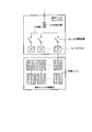
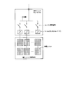
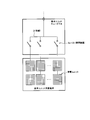
- FIG. 3A to 3C are diagrams illustrating the configuration of the basic unit.
- FIG. 3A is an example including a PCS and a primary transformer, and 1a to 1h are PCSs provided in a basic unit cubicle, which converts DC generated power of each of the eight power generating units in the basic unit solar cell into AC power. To do.
- the AC output of each PCS is connected to the bus 3 via the switchgears 2a to 2h, and the generated power of each power generation unit is converted into AC power and aggregated and boosted to the primary transmission voltage by the primary transformer 4. Is output.
- FIG. 3B is an example including a DC / DC converter, and 1i to 1p are DC / DC converters provided corresponding to the power generation units, and the DC power generation voltage of the solar cell array is boosted to the primary power transmission voltage. Is output.
- a primary transformer is not necessary, which contributes to rationalization of equipment and reduction of loss.
- FIG. 3C omits the installation of the DC / DC converter in the configuration of FIG. 3B and outputs the power generation output of each solar cell array of each power generation unit in parallel.
- the output voltage is lower than that of the other examples, the current in the current collecting line is increased. Therefore, it is preferable to apply a superconducting line to the current collecting line.
- FIGS are diagrams illustrating a related configuration of each facility of a basic unit, a current collecting facility, and a current collecting line in each intermediate substation.
- the configuration example of the basic unit is shown corresponding to FIG. 3A.
- the low-voltage side bus of the intermediate substation and the current collecting line 30t are connected.
- a DC / AC converter (PCS) is inserted between the terminal devices to be converted, and the DC power collected in the current collecting line is converted into AC power and supplied to the secondary transformer.
- PCS DC / AC converter
- the outputs of the five basic units of the basic units 10a to 10e at the start end of the aggregated column are connected to the corresponding terminal devices 23a to 23e of the current collecting cubicle 20 at the same start end.
- the basic unit cubicles of the basic units 10a to 10e are provided with terminal devices 12a to 12e for connecting lines 11a to 11e that output AC power, respectively.
- the current collecting cubicle 20 accommodates five switchgears 21a to 21e and buses 22 corresponding to the five basic unit cubicles, and five terminals for connecting the lines 11a to 11e from the corresponding five basic units.
- One or two terminal devices 24 for connecting the devices 23a to 23e and the bus bar 22 and the power collecting line 30 are provided.
- FIG. 4A an example is shown in which current collecting cubicles are sequentially connected and connected through a current collecting line 30, and the terminal device 24 is described as being provided at two locations except for the current collecting cubicle 20. When connecting with the current collecting line, it is better to provide it at two places corresponding to the current collecting line to be connected.
- the five current collection cubicles (20, 220, 230, 240, 250) are connected to each other via the current collection line 30.
- This connection is suitable for the case where the current collecting line is constituted by a cable or a pipeline air transmission line, but as shown in FIG. 4B, the current collecting line 30 is connected from a line laid in parallel with the current collecting cubicle.
- each current collecting cubicle may be sequentially connected by a T-branch.
- a T-branch connection is suitable.
- the terminal current collection cubicle 250 is connected to the intermediate substation via the current collection line 30t. In the example shown in the figure, intermediate substations are installed corresponding to two columns.
- the power collected for each column can be controlled by the switch units (21a to 21e) of each current collection cubicle to turn on and off the generated power in units of basic units. Further, it is possible to control the opening / closing of the generated power in units of the power generation units by opening / closing the opening / closing devices 2a to 2h of the basic unit cubicles. Further, when each current collection cubicle is connected to the T branch of the current collection line 30, if connected via a switch as shown in FIG. 4B, the aggregate power (10 MW) unit of the current collection cubicle is operated by the operation of the switch. Can control the opening and closing of generated power. However, this switchgear may be omitted.
- secondary transformers Tr1 and Tr2 that boost the intermediate transmission voltage to each intermediate column are provided in the intermediate substation, and the low voltage side of the secondary transformer is connected by a bus line that is divided by a division switch Ds. is doing.
- the intermediate substation bus and its switchgear are configured by gas insulated switchgear. If the circuit breaker of the low voltage side switchgear of the next transformer is omitted and the circuit breaker provided on the high voltage side is also used, the equipment is simplified.
- FIG. 5 is a single-line diagram showing the configuration of the intermediate substation and the interconnected substation. These configurations are the same as the existing commercial substation facilities.
- the high-voltage side of the intermediate substation is configured with double buses as shown in the figure when there are two intermediate transmission lines.
- the voltage of the intermediate transmission line is set to 154 KV, but it may be set to another voltage class depending on the output power aggregated in the intermediate substation or the intermediate transmission line.
- the low-voltage side of the interconnection substation is connected to a separate intermediate transmission line that collects and aggregates the output of the intermediate substation.
- the aggregated power is boosted to the transmission voltage equivalent to the primary system of the commercial power system.
- This example is connected to a 500 KV transmission line, and shows an example in which the voltage is boosted by a two-bank interconnection transformer from the output scale. Since four intermediate transmission lines are connected to the low-voltage side, the transmission line and the transformer are connected to the double bus divided by the bus contact switch.
- the high voltage side is also configured as a double bus that connects 500 KV2 line interconnection transmission lines.
- the present invention can be applied to a large-scale solar substation facility of a scale connected to a primary or secondary commercial power system.
- Output, collection / conversion method using current collection cubicles, output scale of basic units, number of basic units that collect and aggregate current collection facilities, current collection voltage (primary transmission voltage), configuration of current collection line, intermediate substation The configuration and the like can be appropriately set and configured.
Landscapes
- Engineering & Computer Science (AREA)
- Power Engineering (AREA)
- Supply And Distribution Of Alternating Current (AREA)
Abstract
商用電力系統の1次系、又は2次系の送電系統と連系する規模の大規模太陽光発電所の設備構成を提供する。多数の太陽電池アレイを列間にスペースを設けて整列して敷設し、列単位に所定数の太陽電池アレイの発電出力を集電・集約して出力する基本ユニットを構成し、該基本ユニットの出力を所定数毎に集電・集約する集電設備を複数前記列単位に設置する。列毎に設置した前記複数の集電設備を集電線路で接続し、集電設備で集約した発電電力をさらに集電・集約し、列と対応して設置した中間変電所へ出力する。中間変電所で中間電圧に昇圧し中間送電線に出力し、中間送電線で複数の中間変電所の出力を集約し連系変電所へ出力し、連系変電所は1次系又は2次系の送電電圧に昇圧する。
Description
本発明は、太陽光発電所に係り、特に、商用電力系統に連系して太陽電池による発電電力を商用電力系統に供給する大規模な太陽光発電所の設備構成に関する。
近年、環境問題や将来に亘る化石燃料の枯渇等の問題により自然エネルギー、とりわけ太陽光のエネルギーを利用する太陽光発電が注目されており、一般家庭、事業所等で、太陽光発電設備の導入が進んでいる。しかし、これまでに導入されている太陽光発電設備は、家庭や事業所で消費する電力の一部を補う程度の小規模な発電設備である。
それ故、太陽光発電設備を商用系統に連系する場合も、100V、200Vの低圧配電線、又は6.6KVの高圧配電線に接続するものが殆どであり、特別高圧の線路に連系する例は少ない。
また、商用の火力発電所や原子力発電所に匹敵するような大規模太陽光発電設備は未だ例を見ない。
それ故、太陽光発電設備を商用系統に連系する場合も、100V、200Vの低圧配電線、又は6.6KVの高圧配電線に接続するものが殆どであり、特別高圧の線路に連系する例は少ない。
また、商用の火力発電所や原子力発電所に匹敵するような大規模太陽光発電設備は未だ例を見ない。
太陽光発電設備を構成する太陽電池の単位素子の発電電圧は約0.5Vの直流の小電力であるため、太陽光発電設備は、複数の太陽電池単位素子よりなる太陽電池モジュールを複数直列、並列に接続して構成した太陽電池アレイを、さらに、所定数接続し、所要の電圧で直流電力を出力する発電ユニットを構成し、これを交流電力に変換している。
上記の発電ユニットの出力電圧は太陽電池モジュールや、太陽電池アレイの対地絶縁耐力等から限界があり、そのため、交流電力に変換するインバータの変換容量にも自ずと限界がある。
それ故、太陽光発電設備においては、発電ユニットとしての発電出力は、商用の通常の発電機の出力と対比すれば極めて小さい。
上記の発電ユニットの出力電圧は太陽電池モジュールや、太陽電池アレイの対地絶縁耐力等から限界があり、そのため、交流電力に変換するインバータの変換容量にも自ずと限界がある。
それ故、太陽光発電設備においては、発電ユニットとしての発電出力は、商用の通常の発電機の出力と対比すれば極めて小さい。
このため、大規模な太陽光発電所の設備を構築する場合、広大なスペースに多数敷設された太陽電池アレイによる小出力の発電電力を最小限の損失で効率よく集電しなければならない。同時に広範囲に敷設された多数の太陽電池アレイ、変換設備や集電設備等の監視、制御、メンテナンス等が効率的に実施できなければならない。
特許文献1には、複数の上記のような発電ユニットの発電電力を交流電力として集電、昇圧し、さらに、それらを集電して送電線との連系電圧に昇圧することが開示されている。
しかしながら、特許文献1に実施例として開示されたものは、1MW~10MW規模の例であり、すでに実用化されている規模の太陽光発電設備に適用できるが、商用の火力発電所等に匹敵する大規模な太陽光発電所の設備に適用できるものではない。
特許文献1には、複数の上記のような発電ユニットの発電電力を交流電力として集電、昇圧し、さらに、それらを集電して送電線との連系電圧に昇圧することが開示されている。
しかしながら、特許文献1に実施例として開示されたものは、1MW~10MW規模の例であり、すでに実用化されている規模の太陽光発電設備に適用できるが、商用の火力発電所等に匹敵する大規模な太陽光発電所の設備に適用できるものではない。
本発明は、これまでに設置例のない、火力発電所や原子力発電所のような商用の中規模発電所や大規模発電所に匹敵する大出力の大規模な太陽光発電所の設備を提供するものである。
火力発電所や原子力発電所は、発電電力が大であり、少なくとも特別高圧の66KV、154KVの2次系送電系統、又は275KV、500KVの超高圧の一次系送電系統に連系されている。
火力発電所や原子力発電所は、発電電力が大であり、少なくとも特別高圧の66KV、154KVの2次系送電系統、又は275KV、500KVの超高圧の一次系送電系統に連系されている。
太陽電池によってこのような大出力を発電するためには、広大なスペースに多数の太陽電池アレイを敷設し、かつ、太陽電池の発電出力を上記66KV~500KVの電力系統へ連系するために高電圧、大出力の交流電力に変換、集電・集約しなければならない。また、そのために、多数の直流/交流変換設備、発電電力を集電・集約するための種々の開閉設備、送電設備、集約した発電電力に対応した送電電圧に昇圧するための種々の変電設備を設置しなければならないが、それら設備の敷設、設置構成について特許文献1に何らの言及もない。
本発明は、広範囲に多数の太陽電池アレイを敷設した商用の火力発電所または原子力発電所に匹敵する大出力の太陽光発電所における、多数の太陽電池アレイの発電出力を効率的に集電・集約するための太陽電池アレイの敷設構成、太陽電池の発電電力を集電・集約する集約/変換設備、集電設備、集電用の種々の送電設備、変電設備等の大規模太陽光発電所の設備構成を提供するものである。
また、多数の太陽電池アレイの小出力の発電電力を集電・集約し系統に連系するための連系用変電所へ送電する上での特有の技術課題を解決する集約/変換設備および送電設備の構成を提供するものである。
また、多数の太陽電池アレイの小出力の発電電力を集電・集約し系統に連系するための連系用変電所へ送電する上での特有の技術課題を解決する集約/変換設備および送電設備の構成を提供するものである。
本発明は、先ず、複数の太陽電池モジュールを搭載した多数の太陽電池アレイの敷設において、少なくとも、横方向に所定数並設する毎に縦方向の列を区分し、該縦方向の各列の間にスペースを設けて整列して敷設する。もちろん、横方向の列に対しても太陽電池アレイや関連設備のメンテナンス等の利便のために任意に所定の列ごとに点検用の道路等も設けられる。
前記縦方向の各列について、太陽電池アレイの発電出力を集電・集約するための単位として、所定数毎に太陽電池アレイの列を区分し、当該区分された太陽電池アレイ(基本ユニット太陽電池)と対応して、太陽電池の直流発電出力を集電・集約するための集約/変換設備を設置する。この区分された太陽電池アレイ(基本ユニット太陽電池)と集約/変換設備は、太陽光発電所の発電設備の基本ユニットを構成する。
集約/変換設備で集電・集約された基本ユニット太陽電池の直流発電出力は、さらに集電・集約するため、交流に変換して1次送電電圧に昇圧する方式、DC/DCコンバータで直流のまま1次送電電圧に昇圧する方式、また、集電・集約した基本ユニット太陽電池の直流発電電圧で直接出力する方式のいずれかの方式を適用して集約/変換して出力される。
交流に変換する方式の場合は、直流/交流変換インバータ(PCS)とPCSの交流出力を1次送電電圧に昇圧する1次変圧器を設け、1次送電電圧の交流電力で出力される。DC/DCコンバータで昇圧する方式の場合は、昇圧した1次送電電圧の直流電力で出力される。太陽電池アレイの発電出力を直接出力する方式の場合は、太陽電池アレイの発電電圧のまま集約した発電電力が出力される。
いずれにしても集約/変換設備の必要な装置類はキュービクル(基本ユニットキュービクル)に収容される。
交流に変換する方式の場合は、直流/交流変換インバータ(PCS)とPCSの交流出力を1次送電電圧に昇圧する1次変圧器を設け、1次送電電圧の交流電力で出力される。DC/DCコンバータで昇圧する方式の場合は、昇圧した1次送電電圧の直流電力で出力される。太陽電池アレイの発電出力を直接出力する方式の場合は、太陽電池アレイの発電電圧のまま集約した発電電力が出力される。
いずれにしても集約/変換設備の必要な装置類はキュービクル(基本ユニットキュービクル)に収容される。
このように基本ユニットは、基本ユニット太陽電池とその直流発電電力を集電・集約する集約/変換設備を収容した基本ユニットキュービクルによって具現され、大規模太陽光発電所における多数の太陽電池アレイの発電電力を集電・集約するための単位を構成する。
また、前記基本ユニット太陽電池のアレイは、前記PCSの変換容量またはDC/DCコンバータの変換容量に対応して、さらに複数の発電ユニットに区分されて集電され、発電ユニットごとに対応するPCS又はDC/DCコンバータによって変換されてから並列されて集約され、基本ユニットの発電電力として出力される。
前記縦列方向の所定数の基本ユニットに対応して、複数の基本ユニットの発電出力を集電・集約する集電設備を設ける。集電設備は、母線と母線に接続された複数の開閉装置を備え、前記所定数の各基本ユニットの出力を当該開閉装置を介して母線に接続して複数の基本ユニットの出力電力を集電・集約する。
この集電設備は、各列に基本ユニットの数に対応して所定数設置され、列毎に集電線路に接続される。集電線路は各集電設備で集約された複数の基本ユニットの出力電力をさらに集電・集約して中間変電所に送電する。
前記集電設備は、キュービクル(集電キュービクル)に収容され、前記複数の開閉装置、各開閉装置の一端に接続された端末装置、母線に接続された端末装置がキュービクルと一体に設けられる。母線に接続された端末装置は、1箇所又は、例えば、母線の両端に対応して2箇所に設けても良い。
開閉装置が接続された端末装置は対応する各基本ユニットと接続する線路が接続され、母線に接続された端末装置は集電線路が接続される。
開閉装置が接続された端末装置は対応する各基本ユニットと接続する線路が接続され、母線に接続された端末装置は集電線路が接続される。
集電キュービクルと集電線路の接続は、集電線路からT分岐して前記1箇所の端末装置に接続するか、集電線路の端部を集電キュービクルの前記2箇所の端末装置に接続して集電キュービクルを集電線路で順次連接することができる。
集電線路や、基本ユニットと集電設備を接続する線路は架空線、ケーブル又は管路気中線路等によって構成することができる。
基本ユニットにおける集約/変換設備で、直流・交流変換を行い、基本ユニットと集電線路等をケーブルで構成する場合、集電線路は発電所内の広大な敷地に総延長では長距離敷設されるため、充電電流に伴う進相無効電力を消費することになり、発電所の負荷状況によっては無効電力補償装置の設置が必要になる。
基本ユニットにおける集約/変換設備で、直流・交流変換を行い、基本ユニットと集電線路等をケーブルで構成する場合、集電線路は発電所内の広大な敷地に総延長では長距離敷設されるため、充電電流に伴う進相無効電力を消費することになり、発電所の負荷状況によっては無効電力補償装置の設置が必要になる。
一方、基本ユニットにおける集約/変換設備で、DC/DCコンバータによって昇圧する場合には前記の無効電力問題は生じないので、集電線路等をケーブルで構成する場合は、DC/DCコンバータ方式の適用が好ましい。
DC/DCコンバータによる昇圧の場合、例えば、DC/DCコンバータの性能面、直流遮断器などの開閉装置の性能面から、昇圧電圧に制約があり、その場合には集電線路等における通電電流が大になり、損失の増加が問題になる。
また、集約/変換設備でDC/DCコンバータを省略し、太陽電池アレイの発電電圧で送電する場合、損失はさらに増大する。この損失を避けるには、集電線路の一部または全部を超伝導線路で構成することで解決できる。
DC/DCコンバータによる昇圧の場合、例えば、DC/DCコンバータの性能面、直流遮断器などの開閉装置の性能面から、昇圧電圧に制約があり、その場合には集電線路等における通電電流が大になり、損失の増加が問題になる。
また、集約/変換設備でDC/DCコンバータを省略し、太陽電池アレイの発電電圧で送電する場合、損失はさらに増大する。この損失を避けるには、集電線路の一部または全部を超伝導線路で構成することで解決できる。
集電線路は、集電キュービクルと接続するにしたがって、その通電電流が増大するので、線路の電流容量は、それに耐える電流容量が必要である。集電線路で集電キュービクルを連接接続する場合、順次連接する線路の電流容量を増大させると良い。また、T分岐で接続する場合は、分岐ごとに本線の電流容量を増大させると良い。
これらの、縦列毎に発電出力を集電・集約するための、基本ユニットキュービクル、集電キュービクル、集電線路は、前記縦列に沿って設けられたスペースに敷設する。
これらの、縦列毎に発電出力を集電・集約するための、基本ユニットキュービクル、集電キュービクル、集電線路は、前記縦列に沿って設けられたスペースに敷設する。
集電線路で、縦列ごとに集約された電力は1又は複数の縦列に対応して設置される中間変電所に送電される。中間変電所は、1又は複数の2次変圧器を備え、集電線路で集電・集約された電力をさらに集電・集約し中間送電電圧に昇圧する。
基本ユニットにおける集約/変換設備がDC/DCコンバータ方式である場合、又はDC/DCコンバータを省略している場合には、さらに2次変圧器に供給するために、集約した電力を直流から交流に変換するための直流/交流変換設備(PCS)が設置される。
基本ユニットにおける集約/変換設備がDC/DCコンバータ方式である場合、又はDC/DCコンバータを省略している場合には、さらに2次変圧器に供給するために、集約した電力を直流から交流に変換するための直流/交流変換設備(PCS)が設置される。
2次変圧器は、前記縦列毎の1又は複数の集電線路に対応して設け、複数の変圧器を設ける場合には、低圧側の母線を各変圧器バンクに対応して区分開閉器を設けて区分し、該区分した母線に列毎の集電線路を接続する。
中間変電所の高圧側は、連系変電所と接続する中間送電線と接続する。中間送電線は、前記列と対応して設置された複数の中間変電所とT分岐で接続し該中間変電所で集約した発電電力をさらに集電して連系変電所に送電する。
中間送電線は2系統以上敷設し、複数の中間変電所は、区分して別系統の中間送電線に接続すると良い。また、中間変電所の高圧側母線は2重母線とし、中間送電線は2回線以上の線路とすることが好ましい。
前記太陽電池アレイは横方向を東西とし、縦方向を南北として整列し、前記中間変電所、連系変電所、中間送電線は北半球の場合は北側に、南半球の場合は南側に設置するのが良い。
本発明は、広範囲に多数整列して敷設された太陽電池アレイの小出力の発電電力を、前記基本ユニット太陽電池単位に集約/変換設備を設置して集電・集約し、集電設備、集電線路、中間変電所、中間送電線を設置、敷設することによって、前記基本ユニット太陽電池単位又は前記発電ユニット単位で太陽電池の発電出力を順次集電・集約し、商用の電力系統の2次系、さらには、1次系に連系する規模の発電電力を効率よく集電・集約する大出力の大規模太陽光発電所の設備構成を実現したものである。
また、集約/変換設備の機器装置、集電設備の開閉装置、中間変電所の設備機器等は、例えば、連系変電所等に設置した制御所からの遠隔操作によって、前記基本ユニットで集約した電力又はそれ以下の単位で制御可能である。
もちろん、前記集電キュービクルの開閉装置や、前記中間変電所の低圧側フィーダ(集電線路)単位での制御も可能であり、従前の火力発電所や原子力発電所の定期点検のようにメンテナンスの度に発電所の大出力の発電が停止することはない。
縦列ごとの発電電力の集電・集約において、直流送電を適用すれば無効電力対策が不要になり、変換設備における損失も低減でき、また、超伝導送電を適用すれば、集電・集約に伴う線路の損失を大幅に低減できる。
また、太陽電池アレイの縦の列を南北に構成し、列間にスペースを確保して当該スペースに集約/変換設備や集電キュービクル、集電線路を設置しているので、設備のメンテナンス空間が確保されており、迅速な対応が可能である。
さらに、これら設備による太陽電池アレイに及ぼす影の影響を最小限にすることができる。また、中間変電所、中間送電線、連系用変電所等の大型構築物は、太陽電池アレイの縦の列の北側(北半球)又は南側(南半球)に設置するので、これらの影が太陽電池アレイに及ぼす影響も避けることができる。
図面を参照して本発明を説明する。図1は、本発明に係る太陽光発電所の全体のレイアウトを示す略図である。図示の例は、発電所出力が原子力発電所の1ユニットに匹敵する1GW(100万KW)で、275KV又は500KVの1次系超高圧送電線に連系する例を想定したものである。
基本ユニットとして示す区分は、2MWの発電電力を集約した単位であり、所定数の太陽電池アレイで構成する複数の発電ユニットの発電電力を複数の直流/交流変換装置(PCS)又はDC/DCコンバータにより変換し、変換した出力を並列して集約し、所定の1次送電電圧に昇圧して出力するものである。
PCSを介して変換する場合、基本ユニット太陽電池における前記複数の発電ユニットの変換された交流電力を集約して1次変圧器により1次送電電圧に昇圧する。
基本ユニットとして示す区分は、2MWの発電電力を集約した単位であり、所定数の太陽電池アレイで構成する複数の発電ユニットの発電電力を複数の直流/交流変換装置(PCS)又はDC/DCコンバータにより変換し、変換した出力を並列して集約し、所定の1次送電電圧に昇圧して出力するものである。
PCSを介して変換する場合、基本ユニット太陽電池における前記複数の発電ユニットの変換された交流電力を集約して1次変圧器により1次送電電圧に昇圧する。
DC/DCコンバータは発電ユニットの太陽電池アレイの発電出力電圧を1次送電電圧に昇圧し直流電力を出力するので、1次変圧器は不要であり、基本ユニットにおける損失を軽減できる。この場合も、前記複数の発電ユニット毎の発電出力をDC/DCコンバータで昇圧し他出力を並列して集約し出力する。
DC/DCコンバータを省略する場合は、前記発電ユニットの太陽電池アレイの発電出力を並列又は直並列して集約し、当該発電電圧で直流電力を出力する。
基本ユニットにおける集電・集約のために必要なPCS、1次変圧器、DC/DCコンバータ、開閉装置等の設備はキュービクル(基本ユニットキュービクル)に収容される。
DC/DCコンバータを省略する場合は、前記発電ユニットの太陽電池アレイの発電出力を並列又は直並列して集約し、当該発電電圧で直流電力を出力する。
基本ユニットにおける集電・集約のために必要なPCS、1次変圧器、DC/DCコンバータ、開閉装置等の設備はキュービクル(基本ユニットキュービクル)に収容される。
図の例では、矩形で示す単位が基本ユニットで、南北(縦)方向に25ユニット並設した縦列を東西(横)方向に20列整列して敷設されている。基本ユニットの集電・集約単位の発電電力は交流で出力する場合を想定して2MWを例示しているがこれに限るものではない。また、集約/変換の方式に対応して適切に規模に設定される。
基本ユニットの出力電圧(1次送電電圧)は、基本ユニットの出力や、変換構成により、また、後述する集電キュービクルによる基本ユニットの集電数に応じて設定されるが、6.6KV~33KV程度の電圧階級が良いが、この範囲に限るものではなく、前記出力容量の設定と同様に適切な値に設定される。
縦列方向に25ユニット並設した基本ユニットの出力を集電するために5基本ユニット毎に集電キュービクルを設置し、10MWの発電電力に集電・集約する。さらに、集電キュービクルは縦1列に5箇所設置され、それら5箇所の集電キュービクルを接続する集電線路が敷設されて、1列毎の集電線路で、50MWの発電電力が集電・集約される。
縦列方向に25ユニット並設した基本ユニットの出力を集電するために5基本ユニット毎に集電キュービクルを設置し、10MWの発電電力に集電・集約する。さらに、集電キュービクルは縦1列に5箇所設置され、それら5箇所の集電キュービクルを接続する集電線路が敷設されて、1列毎の集電線路で、50MWの発電電力が集電・集約される。
集電線路で集約した電力をさらに集約し高電圧に昇圧するために中間変電所を設置する。図の例では、2列ごとに中間変電所が設置され、集電線路は中間変電所に接続され、2列に対応する100MWの発電電力が集約され、2次変圧器によって154KVに昇圧され、中間送電線に接続して連系変電所に送電される。
中間変電所の変圧器は複数バンクが好ましく、例えば、前記縦列毎の集電線路に対応して50MW対応の変圧器2バンクとするのが良い。
なお、集電線路に直流送電が適用される場合は、中間変電所の低圧側に直/交変換設備(PCS)が設置される。
中間変電所の変圧器は複数バンクが好ましく、例えば、前記縦列毎の集電線路に対応して50MW対応の変圧器2バンクとするのが良い。
なお、集電線路に直流送電が適用される場合は、中間変電所の低圧側に直/交変換設備(PCS)が設置される。
図の例では、中間変電所が10箇所設置されているが、その中央部に設置される中間変電所には連系変電所が併設される。そして、図で当該変電所より左側の中間変電所と、右側の中間変電所とはそれぞれ別系統の中間送電線に接続され、両中間送電線は、連系変電所の低圧側母線に接続される。
また、図では、集電線路が集電キュービクルを連接するように記載しているが、集電線路からT分岐させて集電キュービクルの母線に接続しても良い。
集電線路は太陽電池アレイが敷設されたスペース内に敷設されるので、架空線路を敷設する場合は、太陽電池パネルに与る支持物の影の影響を最小限にしなければならない。前記の影の影響を避けるには、ケーブルや管路気中線路の敷設が好ましい。そして、集電キュービクルを連接する場合は連接区間毎に順次通電容量を増加した線路を敷設すればよい。また、T分岐で接続する場合は、分岐部を含め、集電キュービクルと接続する分岐線や端末部(ケーブルヘッド)を装備し、分岐区間毎に順次通電容量が増加するケーブルを予め製作しておき、敷設現場で前記集電設備の端末と集電ケーブルに接続する手法(プレハブ工法)の適用が好ましい。
集電線路は太陽電池アレイが敷設されたスペース内に敷設されるので、架空線路を敷設する場合は、太陽電池パネルに与る支持物の影の影響を最小限にしなければならない。前記の影の影響を避けるには、ケーブルや管路気中線路の敷設が好ましい。そして、集電キュービクルを連接する場合は連接区間毎に順次通電容量を増加した線路を敷設すればよい。また、T分岐で接続する場合は、分岐部を含め、集電キュービクルと接続する分岐線や端末部(ケーブルヘッド)を装備し、分岐区間毎に順次通電容量が増加するケーブルを予め製作しておき、敷設現場で前記集電設備の端末と集電ケーブルに接続する手法(プレハブ工法)の適用が好ましい。
図では、集電キュービクルと集電線路が太陽電池アレイと重ねて表記されているが、実際には、基本ユニットの縦列間に設けられるスペースに設置される。基本ユニットに対応する集約/変換設備を収容するキュービクル(基本ユニットキュービクル)の設置も同様である。
縦の列が、南北方向であれば、キュービクル等の影は主に縦列間のスペースに映るので、太陽電池アレイに対する影響が最小限になる。
縦の列が、南北方向であれば、キュービクル等の影は主に縦列間のスペースに映るので、太陽電池アレイに対する影響が最小限になる。
図2は、前記の2MWの基本ユニットにおける太陽電池アレイ(基本ユニット太陽電池)の敷設状況を示す図である。図は、140Wのモジュール10モジュールを搭載した太陽電池アレイ(1.4KW/アレイ)の敷設例である。図で8つに区分される1つが250KWの発電ユニットを構成する太陽電池アレイであり、当該発電ユニット単位の発電出力は直流で、図の右側又は左側の前記縦列毎のスペースに設置される基本ユニットキュービクルに導入される。
本例では、10モジュールを搭載した太陽電池アレイ全792000パネル、500台の基本ユニットキュービクル、100台の集電キュービクル、10箇所の特別高圧の中間変電所、1箇所の連系変電所が約3600ヘクタール余の敷地に敷設設置されることになる。
なお、図中の発電ユニット間のスペースは、メンテナンスの必要に応じて任意に設けられるスペースである。
なお、図中の発電ユニット間のスペースは、メンテナンスの必要に応じて任意に設けられるスペースである。
図3A~Cは、基本ユニットの構成を説明する図である。
図3AはPCS、1次変圧器を備える例であり、1a~1hは、基本ユニットキュービクルに設けられたPCSであり、基本ユニット太陽電池における8つの各発電ユニットの直流発電電力を交流電力に変換する。各PCSの交流出力は開閉装置2a~2hを介して母線3に接続され、前記各発電ユニットの発電電力が交流電力に変換されて集約され、1次変圧器4によって1次送電電圧に昇圧されて出力される。
図3AはPCS、1次変圧器を備える例であり、1a~1hは、基本ユニットキュービクルに設けられたPCSであり、基本ユニット太陽電池における8つの各発電ユニットの直流発電電力を交流電力に変換する。各PCSの交流出力は開閉装置2a~2hを介して母線3に接続され、前記各発電ユニットの発電電力が交流電力に変換されて集約され、1次変圧器4によって1次送電電圧に昇圧されて出力される。
図3Bは、DC/DCコンバータを備える例であり、1i~1pが前記発電ユニットに対応して設けられたDC/DCコンバータであり、太陽電池アレイの直流発電電圧が1次送電電圧に昇圧されて出力される。本例の場合は、1次変圧器が不要になり設備の合理化と損失の軽減に資する。
図3Cは、図3Bの構成におけるDC/DCコンバータの設置を省略したもので、前記各発電ユニットの各太陽電池アレイの発電出力を並列して出力するものである。この例の場合、出力電圧が他の例よりも低電圧でなるので、集電線路の電流が大になることから、集電線路に超伝導線路を適用することが好ましい。
図3Cは、図3Bの構成におけるDC/DCコンバータの設置を省略したもので、前記各発電ユニットの各太陽電池アレイの発電出力を並列して出力するものである。この例の場合、出力電圧が他の例よりも低電圧でなるので、集電線路の電流が大になることから、集電線路に超伝導線路を適用することが好ましい。
図4A、4Bは、中間変電所単位の基本ユニット、集電設備、集電線路の各設備の関連構成を示す図である。
なお、図では、基本ユニットの構成例として図3Aに対応して記載しているが、図3B又は図3Cの構成例の場合には、中間変電所の低圧側母線と集電線路30tが接続される端末装置の間に直/交変換設備(PCS)が挿入され、集電線路で集約された直流電力を交流電力に変換し、2次変圧器に供給される。
前記の集約される縦列の始端の基本ユニット10a~10eの5箇所の基本ユニットの出力が、対応する同始端の集電キュービクル20の端末装置23a~23eに接続される。基本ユニット10a~10eの基本ユニットキュービクルには、それぞれ交流電力を出力する線路11a~11eを接続するための端末装置12a~12eが設けられている。
なお、図では、基本ユニットの構成例として図3Aに対応して記載しているが、図3B又は図3Cの構成例の場合には、中間変電所の低圧側母線と集電線路30tが接続される端末装置の間に直/交変換設備(PCS)が挿入され、集電線路で集約された直流電力を交流電力に変換し、2次変圧器に供給される。
前記の集約される縦列の始端の基本ユニット10a~10eの5箇所の基本ユニットの出力が、対応する同始端の集電キュービクル20の端末装置23a~23eに接続される。基本ユニット10a~10eの基本ユニットキュービクルには、それぞれ交流電力を出力する線路11a~11eを接続するための端末装置12a~12eが設けられている。
集電キュービクル20には、5つの基本ユニットキュービクルに対応して5つの開閉装置21a~21e及び母線22が収容され、対応する5つの基本ユニットからの線路11a~11eを接続するための5つの端末装置23a~23e及び母線22と集電線路30を接続するための端末装置24が1箇所又は2箇所設けられている。
図4Aの例では、集電キュービクルを集電線路30で順次連接接続する例を示しており、端末装置24は始端の集電キュービクル20を除き2箇所設けるよう記載している。集電線路で連接する場合には、このように、接続される集電線路に対応して2箇所に設けたほうが良い。
5つの集電キュービクル(20,220,230,240,250)は集電線路30を介して連接接続される。この接続は、集電線路をケーブル又は管路気中送電線路で構成する場合に好適であるが、図4Bに示すように、集電線路30を集電キュービクルと並行して敷設される線路から、各集電キュービクルと順次T分岐で接続しても良い。集電線路を架空送電線で構成する場合は、T分岐接続が好適である。
終端の集電キュービクル250は集電線路30tを介して中間変電所と接続する。図の例では、縦列の2列に対応して中間変電所が設置されている。
図4Aの例では、集電キュービクルを集電線路30で順次連接接続する例を示しており、端末装置24は始端の集電キュービクル20を除き2箇所設けるよう記載している。集電線路で連接する場合には、このように、接続される集電線路に対応して2箇所に設けたほうが良い。
5つの集電キュービクル(20,220,230,240,250)は集電線路30を介して連接接続される。この接続は、集電線路をケーブル又は管路気中送電線路で構成する場合に好適であるが、図4Bに示すように、集電線路30を集電キュービクルと並行して敷設される線路から、各集電キュービクルと順次T分岐で接続しても良い。集電線路を架空送電線で構成する場合は、T分岐接続が好適である。
終端の集電キュービクル250は集電線路30tを介して中間変電所と接続する。図の例では、縦列の2列に対応して中間変電所が設置されている。
列毎に集電される電力は、各集電キュービクルの各開閉装置(21a~21eが該当)により基本ユニット単位で発電電力の投入開放が制御できる。さらに、基本ユニットキュービクルの開閉装置2a~2hの開閉操作により前記発電ユニット単位に発電電力を開放投入が制御できる。
また、各集電キュービクルを集電線路30のT分岐と接続する場合、図4Bに示すように開閉装置を介して接続すれば、当該開閉装置の操作により集電キュービクルの集約電力(10MW)単位で発電電力の投入開放が制御できる。しかしこの開閉装置は省略しても良い。
また、各集電キュービクルを集電線路30のT分岐と接続する場合、図4Bに示すように開閉装置を介して接続すれば、当該開閉装置の操作により集電キュービクルの集約電力(10MW)単位で発電電力の投入開放が制御できる。しかしこの開閉装置は省略しても良い。
図の例では、中間変電所に縦列毎に中間送電電圧に昇圧する2次変圧器Tr1、Tr2を設けており、2次変圧器の低圧側は、区分開閉器Dsで区分される母線で連絡している。
終端の集電キュービクル250と中間変電所を接続する部分の集電線路30tを管路気中送電線路で構成し、中間変電所の母線とその開閉装置をガス絶縁開閉設備で構成する場合、2次変圧器の低圧側開閉装置の遮断器を省略し、高圧側に設けた遮断器で兼用すれば、設備が簡略化される。
終端の集電キュービクル250と中間変電所を接続する部分の集電線路30tを管路気中送電線路で構成し、中間変電所の母線とその開閉装置をガス絶縁開閉設備で構成する場合、2次変圧器の低圧側開閉装置の遮断器を省略し、高圧側に設けた遮断器で兼用すれば、設備が簡略化される。
図5は、中間変電所と連系変電所の構成を示す単線結線図である。これらの構成は、既存の商用の変電所設備と同様の構成である。
中間変電所の高圧側は、中間送電線を2回線とする場合には、図示のように2重母線で構成する。本例では中間送電線の電圧は154KVに設定されているが、中間変電所や中間送電線で集約する出力電力により他の電圧階級に設定しても良い。
中間変電所の高圧側は、中間送電線を2回線とする場合には、図示のように2重母線で構成する。本例では中間送電線の電圧は154KVに設定されているが、中間変電所や中間送電線で集約する出力電力により他の電圧階級に設定しても良い。
連系変電所の低圧側には、中間変電所の出力を集電・集約した別系統の中間送電線が接続され、それら集約された電力を商用電力系統の1次系相当の送電電圧に昇圧する。
本例は、500KV送電線に連系するものであり、出力規模から2バンクの連系変圧器で昇圧する例を示している。低圧側は4回線の中間送電線が接続されるので、母線連絡用開閉器で区分した2重母線に送電線、変圧器をそれぞれ接続している。高圧側も500KV2回線の連系用送電線を接続する2重母線に構成されている。
本例は、500KV送電線に連系するものであり、出力規模から2バンクの連系変圧器で昇圧する例を示している。低圧側は4回線の中間送電線が接続されるので、母線連絡用開閉器で区分した2重母線に送電線、変圧器をそれぞれ接続している。高圧側も500KV2回線の連系用送電線を接続する2重母線に構成されている。
1GWの実施例で説明したが、本発明は1次系又は2次系の商用電力系統に連系する規模の大規模太陽光変電所設備に適用できるものであり、発電規模により基本ユニットの発電出力や、集電キュービクルによる集約/変換方式、基本ユニットの出力規模、集電設備で集電・集約する基本ユニット数、集電電圧(1次送電電圧)、集電線路の構成、中間変電所の構成等を適宜設定して構成できるものである。
1a~1h…直流/交流変換装置(PCS)、1i~1p…DC/DCコンバータ、2a~2h…基本キュービクルの開閉装置、3…基本キュービクルの母線、4…1次持変圧器、10a~10e,120,130,140,150…基本ユニット、11a~11e…基本ユニットの接続線路、12a~12e…基本ユニットの端末装置、20,220,230,240,250…集電キュービクル、21a~21e…集電キュービクルの開閉装置、22…集電キュービクルの母線、23a~23e,24…集電キュービクルの端末装置、30,30t …集電線路。
Claims (15)
- 複数の太陽電池モジュールを搭載した太陽電池アレイを多数整列し、少なくとも横方向に所定数並設する毎に縦方向の列を区分し、該縦方向の各列の間にスペースを設けて敷設し、
前記各縦列方向の太陽電池アレイ列を該縦列方向に所定数毎に基本ユニット太陽電池として区分し、該区分した基本ユニット太陽電池毎に、前記縦列に沿うスペースに前記基本ユニット太陽電池の発電出力を集電・集約する集約/変換設備を設置し、集約した基本ユニット太陽電池の発電出力を直接又は昇圧して出力し、
前記縦列方向に設置された所定数の前記集約/変換設備毎に、母線と接続した複数の開閉装置を備える集電設備を前記スペースに設置し、前記所定数の各集約/変換設備の出力を前記各開閉装置と接続して当該集約/変換設備の出力電力を集電・集約し、
前記各縦列に当該列毎の前記各集電設備を集電線路に接続して前記列ごとに各集電設備で集約された発電電力を集電・集約し、
前記縦列の一方の端側に1又は複数の前記縦列と対応して中間変電所を設置し、
前記中間変電所の低圧側に前記縦列毎の集電線路を接続し、集電線路を介して縦列毎に集電・集約された発電電力をさらに集約し、
前記中間変電所は少なくとも1または複数の2次変圧器を備え、前記集電線路により送電された電力を中間送電電圧に昇圧し、
前記縦列に対応して複数設置された前記各中間変電所の電力を商用系統と連系するための連系変電所を設置し、
前記中間変電所の高圧側と前記連系変電所を接続する中間送電線を敷設し、前記連系変電所は中間送電線から受電して集約された発電電力を商用電力系統の1次系または2次系の送電電圧に昇圧し商用系統と連系することを特徴とする大規模太陽光発電所。 - 前記集約/変換設備はキュービクルに収容され、少なくとも前記基本ユニット太陽電池の直流発電電力を交流電力に変換する直/交変換設備(PCS)、該PCSの交流出力を並列するための開閉装置、該開閉器で並列され集約された前記PCSの交流出力を1次送電電圧に昇圧する1次変圧器を備えることを特徴とする請求項1に記載の大規模太陽光発電所。
- 前記集約/変換設備はキュービクルに収容され、少なくとも前記基本ユニット太陽電池の直流発電電力を1次送電電圧に昇圧するDC/DCコンバータ、該DC/DCコンバータの出力を並列するための開閉装置を備え、
前記中間変電所に、さらに直/交変換設備を備え、前記集電線路により送電された直流電力を交流に変換することを特徴とする請求項1に記載の大規模太陽光発電所。 - 前記集約/変換設備はキュービクルに収容され、少なくとも前記基本ユニット太陽電池の複数の発電ユニットの直流発電電力を並列するための開閉装置を備え、
前記中間変電所に、さらに直/交変換設備を備え、前記集電線路により送電された直流電力を交流に変換することを特徴とする請求項1に記載の大規模太陽光発電所。 - 前記集電設備は、少なくとも前記開閉装置と母線をキュービクルに収容し、前記複数の各開閉装置に接続され、前記集約/変換設備の出力と接続される端末装置及び、前記母線に接続され前記集電線路が接続される端末装置が一体に設けられていることを特徴とする請求項1から4のいずれかに記載の大規模太陽光発電所。
- 前記集電設備の1部は、前記母線に接続し前記集電線路が接続される端末装置が2箇所設けられ、それぞれの端末装置に集電線路が接続されて集電設備が連接接続されることを特徴とする請求項5に記載の大規模太陽光発電所。
- 前記集電設備は、前記母線に接続し、前記集電線路が接続される端末装置が1箇所設けられ、それぞれの端末装置に集電線路がT分岐で接続されることを特徴とする請求項5に記載の大規模太陽光発電所。
- 集電線路は、分岐部及び端末装置(ケーブルヘッド)が予め一体に形成されたケーブルが敷設されるプレハブ工法のケーブルが敷設されることを特徴とする請求項7に記載の大規模太陽光発電所。
- 集電線路が直流送電線路であることを特徴とする請求項3または4に記載の大規模太陽光発電所。
- 集電線路が超伝導線路で構成されることを特徴とする請求項9に記載の大規模太陽光発電所。
- 前記中間変電所の低圧側の母線には、設置される2次変圧器の低圧側の接続毎に母線を区分する区分開閉器が設けられ、該区分された母線に前記列毎の集電線路が接続されることを特徴とする請求項1の何れかに記載の大規模太陽光発電所。
- 前記中間変電所の高圧側母線は2重母線に構成され、前記中間送電線は少なくとも2回線以上であることを特徴とする請求項11に記載の大規模太陽光発電所。
- 前記中間送電線は少なくとも2系統以上であり、前記中間変電所は何れかの系統の前記中間送電線と接続することを特徴とする請求項12に記載の大規模太陽光発電所。
- 前記整列して敷設される太陽電池アレイの整列の縦方向は南北であり、横方向は東西であることを特徴とする請求項1に記載の大規模太陽光発電所。
- 前記中間変電所を設置する前記縦列の端部は北側又は南側の一方側であることを特徴とする請求項14に記載の大規模太陽光発電所。
Applications Claiming Priority (2)
| Application Number | Priority Date | Filing Date | Title |
|---|---|---|---|
| JP2011097753 | 2011-04-26 | ||
| JP2011-097753 | 2011-04-26 |
Publications (1)
| Publication Number | Publication Date |
|---|---|
| WO2012147687A1 true WO2012147687A1 (ja) | 2012-11-01 |
Family
ID=47072206
Family Applications (1)
| Application Number | Title | Priority Date | Filing Date |
|---|---|---|---|
| PCT/JP2012/060847 Ceased WO2012147687A1 (ja) | 2011-04-26 | 2012-04-23 | 大規模太陽光発電所 |
Country Status (1)
| Country | Link |
|---|---|
| WO (1) | WO2012147687A1 (ja) |
Citations (2)
| Publication number | Priority date | Publication date | Assignee | Title |
|---|---|---|---|---|
| JP2007274841A (ja) * | 2006-03-31 | 2007-10-18 | Toshiba Corp | 太陽光発電システムおよび太陽光発電プラント |
| JP2010213384A (ja) * | 2009-03-06 | 2010-09-24 | Chugoku Electric Power Co Inc:The | 分散型電源システム |
-
2012
- 2012-04-23 WO PCT/JP2012/060847 patent/WO2012147687A1/ja not_active Ceased
Patent Citations (2)
| Publication number | Priority date | Publication date | Assignee | Title |
|---|---|---|---|---|
| JP2007274841A (ja) * | 2006-03-31 | 2007-10-18 | Toshiba Corp | 太陽光発電システムおよび太陽光発電プラント |
| JP2010213384A (ja) * | 2009-03-06 | 2010-09-24 | Chugoku Electric Power Co Inc:The | 分散型電源システム |
Similar Documents
| Publication | Publication Date | Title |
|---|---|---|
| EP2478608B1 (en) | A power collection and distribution system | |
| US9231405B2 (en) | System and method for operating a distributed energy generating plant using a renewable source of energy | |
| DK2810353T3 (en) | DC CONNECTION FORM FOR WIND FARM WITH SINGLE mVDC-ASSEMBLY GRID | |
| CN204103503U (zh) | 一种基于中高压直流接入的光伏并网发电系统 | |
| CN205335975U (zh) | 光伏智能变电站 | |
| JP2012515519A (ja) | 電力供給システムおよびそのための太陽電池装置 | |
| Sun et al. | Identifying opportunities for medium voltage DC systems in Australia | |
| CN112018890B (zh) | 一种用于高海拔地区的模块化预制舱式110kV光伏汇集站 | |
| CN115459460A (zh) | 一种用于氢电耦合的制氢方法及其控制系统 | |
| ITPI20110142A1 (it) | Apparato di trasformazione di energia prodotta da fonti rinnovabili e metodo di gestione relativo | |
| CN104967035A (zh) | 光伏发电专用逆配变一体化智能集成式预装变电站 | |
| CN220475449U (zh) | 一种并联型高可靠交直流电源 | |
| CN109474004A (zh) | 光伏建筑一体化微电网架构方案 | |
| WO2012147687A1 (ja) | 大規模太陽光発電所 | |
| CN214707177U (zh) | 一种用于紧凑型布置的预制式储能电池系统 | |
| CN210007408U (zh) | 一种带有微网系统的变电站连接结构 | |
| KR101737970B1 (ko) | 하이브리드 수배전반 | |
| JP7370850B2 (ja) | 電力供給システムおよび受変電設備 | |
| CN114336617A (zh) | 一种核能供热厂的供电系统 | |
| CN201821117U (zh) | 基于低频输电和高压直流输电的风电场接入装置 | |
| CN222508814U (zh) | 一种分布式光伏发电装置和系统 | |
| CN205992745U (zh) | 一种智能紧凑型光伏发电用预装式变电站 | |
| CN223181868U (zh) | 一种吉瓦级电化学储能站及站用电系统 | |
| CN209344805U (zh) | 光伏并网系统 | |
| Zoroofi et al. | Commutation failure propagation in multi-infeed HVDC systems |
Legal Events
| Date | Code | Title | Description |
|---|---|---|---|
| 121 | Ep: the epo has been informed by wipo that ep was designated in this application |
Ref document number: 12776269 Country of ref document: EP Kind code of ref document: A1 |
|
| NENP | Non-entry into the national phase |
Ref country code: DE |
|
| 122 | Ep: pct application non-entry in european phase |
Ref document number: 12776269 Country of ref document: EP Kind code of ref document: A1 |
|
| NENP | Non-entry into the national phase |
Ref country code: JP |