WO2012147277A1 - 中継サーバ及び中継通信システム - Google Patents
中継サーバ及び中継通信システム Download PDFInfo
- Publication number
- WO2012147277A1 WO2012147277A1 PCT/JP2012/002272 JP2012002272W WO2012147277A1 WO 2012147277 A1 WO2012147277 A1 WO 2012147277A1 JP 2012002272 W JP2012002272 W JP 2012002272W WO 2012147277 A1 WO2012147277 A1 WO 2012147277A1
- Authority
- WO
- WIPO (PCT)
- Prior art keywords
- terminal
- master
- backup
- maintenance
- identification information
- Prior art date
- Legal status (The legal status is an assumption and is not a legal conclusion. Google has not performed a legal analysis and makes no representation as to the accuracy of the status listed.)
- Ceased
Links
Images




Classifications
-
- G—PHYSICS
- G06—COMPUTING OR CALCULATING; COUNTING
- G06F—ELECTRIC DIGITAL DATA PROCESSING
- G06F11/00—Error detection; Error correction; Monitoring
- G06F11/07—Responding to the occurrence of a fault, e.g. fault tolerance
- G06F11/16—Error detection or correction of the data by redundancy in hardware
- G06F11/20—Error detection or correction of the data by redundancy in hardware using active fault-masking, e.g. by switching out faulty elements or by switching in spare elements
- G06F11/202—Error detection or correction of the data by redundancy in hardware using active fault-masking, e.g. by switching out faulty elements or by switching in spare elements where processing functionality is redundant
- G06F11/2023—Failover techniques
- G06F11/2028—Failover techniques eliminating a faulty processor or activating a spare
-
- G—PHYSICS
- G06—COMPUTING OR CALCULATING; COUNTING
- G06F—ELECTRIC DIGITAL DATA PROCESSING
- G06F11/00—Error detection; Error correction; Monitoring
- G06F11/07—Responding to the occurrence of a fault, e.g. fault tolerance
- G06F11/16—Error detection or correction of the data by redundancy in hardware
- G06F11/20—Error detection or correction of the data by redundancy in hardware using active fault-masking, e.g. by switching out faulty elements or by switching in spare elements
- G06F11/202—Error detection or correction of the data by redundancy in hardware using active fault-masking, e.g. by switching out faulty elements or by switching in spare elements where processing functionality is redundant
- G06F11/2038—Error detection or correction of the data by redundancy in hardware using active fault-masking, e.g. by switching out faulty elements or by switching in spare elements where processing functionality is redundant with a single idle spare processing component
-
- H—ELECTRICITY
- H04—ELECTRIC COMMUNICATION TECHNIQUE
- H04L—TRANSMISSION OF DIGITAL INFORMATION, e.g. TELEGRAPHIC COMMUNICATION
- H04L63/00—Network architectures or network communication protocols for network security
- H04L63/02—Network architectures or network communication protocols for network security for separating internal from external traffic, e.g. firewalls
- H04L63/0272—Virtual private networks
-
- H—ELECTRICITY
- H04—ELECTRIC COMMUNICATION TECHNIQUE
- H04L—TRANSMISSION OF DIGITAL INFORMATION, e.g. TELEGRAPHIC COMMUNICATION
- H04L69/00—Network arrangements, protocols or services independent of the application payload and not provided for in the other groups of this subclass
- H04L69/40—Network arrangements, protocols or services independent of the application payload and not provided for in the other groups of this subclass for recovering from a failure of a protocol instance or entity, e.g. service redundancy protocols, protocol state redundancy or protocol service redirection
-
- G—PHYSICS
- G06—COMPUTING OR CALCULATING; COUNTING
- G06F—ELECTRIC DIGITAL DATA PROCESSING
- G06F11/00—Error detection; Error correction; Monitoring
- G06F11/07—Responding to the occurrence of a fault, e.g. fault tolerance
- G06F11/16—Error detection or correction of the data by redundancy in hardware
- G06F11/20—Error detection or correction of the data by redundancy in hardware using active fault-masking, e.g. by switching out faulty elements or by switching in spare elements
- G06F11/202—Error detection or correction of the data by redundancy in hardware using active fault-masking, e.g. by switching out faulty elements or by switching in spare elements where processing functionality is redundant
- G06F11/2048—Error detection or correction of the data by redundancy in hardware using active fault-masking, e.g. by switching out faulty elements or by switching in spare elements where processing functionality is redundant where the redundant components share neither address space nor persistent storage
Definitions
- the present invention mainly relates to a relay server that enables communication between terminals connected to different LANs (Local Area Networks).
- LANs Local Area Networks
- VPN virtual private network
- This VPN is used, for example, for applications in which terminals connected to LANs at a plurality of bases provided for each region communicate via the Internet. If the VPN is used, another remote LAN can be used as if it were a directly connected network.
- the VPN is used for, for example, a remote maintenance of a terminal provided at another base.
- a maintenance target terminal can receive remote maintenance or the like from a device connected to another LAN at a remote location.
- Patent Document 1 discloses a management system via this type of network.
- This management system is constructed so as to straddle building owners, equipment maintenance companies, and electrical equipment manufacturers.
- the building owner installs electrical equipment and an operation control management device for controlling the electrical equipment in the building owned by the building owner.
- This operation control management device is configured to be accessible via a network such as the Internet.
- the equipment maintenance company is entrusted with the management of the electrical equipment by the building owner, and has obtained permission from the electrical equipment manufacturer to access the operation control management device. Accordingly, the equipment maintenance company can perform maintenance work on the electrical equipment from a remote location via a network such as the Internet.
- the present invention has been made in view of the above circumstances, and an object of the present invention is to manage a relay server used in a relay communication system constructed by a plurality of relay servers even when the management-side relay server is stopped. It is an object of the present invention to provide a configuration capable of continuing the operation of the relay communication system without changing the setting of the relay server.
- a relay server having the following configuration. That is, the relay server includes a database storage unit, a switching control unit, an identification information storage unit, an identification information registration unit, and a stored information transmission unit.
- the database storage unit relates to a relay communication system configured to include a relay server capable of communicating with each other via an external server that stores identification information and network information in association with each other, and information for managing the relay communication system Is stored.
- the switching control unit can switch between operating as a master managing the relay communication system and operating as a backup of the master.
- the identification information storage unit stores master identification information, which is identification information set for itself when operating as a master, and backup identification information, which is identification information set for itself when operating as a backup.
- the identification information registration unit registers the master identification information and its own network information in the external server when operating as a master, and when operating as a backup, the backup identification information and its own network information. Are registered in the external server.
- the storage information transmission unit transmits the contents of the database storage unit to another relay server operating as a master when switching from a state operating as a master to a state operating as a backup.
- the storage information transmitting unit when operating as a master, preferably transmits the contents of the database storage unit to another relay server operating as a backup.
- the contents stored in the database storage unit of the relay server that operates as a master can be stored in the relay server that operates as a backup. Therefore, even when a sudden failure occurs in a relay server that operates as a master, it is possible to operate another relay server as a master while (at least) taking over the contents stored in the database storage unit. .
- the storage information transmission unit automatically transmits the stored contents of the database storage unit every set time.
- the storage information transmission unit preferably transmits the stored contents of the database storage unit at the timing when the operation unit is operated.
- the other relay server operating as a backup can update the spare data for switching to the master when the operation unit is operated. Therefore, for example, preliminary data can be created and updated flexibly according to the situation, for example, the operation unit is operated at the timing when the storage content of the database storage unit is greatly changed in the relay server operating as the master.
- the relay communication system includes a plurality of relay servers with management functions and a plurality of relay servers to be managed.
- the relay server to be managed can communicate with the relay server with a management function via an external server that stores identification information and network information in association with each other.
- the relay server with a management function includes a database storage unit, a switching control unit, an identification information storage unit, an identification information registration unit, and a stored information transmission unit.
- the database storage unit stores information for managing the managed relay server.
- the switching control unit can switch between operating as a master that manages the managed relay server and operating as a backup of the master.
- the identification information storage unit stores master identification information, which is identification information set for itself when operating as a master, and backup identification information, which is identification information set for itself when operating as a backup.
- the identification information registration unit registers the master identification information and its own network information in the external server when operating as a master, and when operating as a backup, the backup identification information and its own network information. Are registered in the external server.
- the storage information transmission unit transmits the contents of the database storage unit to another relay server with a management function that operates as a master when the state that operates as a master is switched to a state that operates as a backup. Note that one of the relay servers with management functions operates as a master, and the other relay servers with management functions operate as backups.
- the functional block diagram which shows the structure of an external server.
- the functional block diagram which shows the structure of a 1st maintenance terminal.
- the sequence diagram which shows the flow of a process when a connection job is produced The sequence diagram which shows the flow of the process performed at the time of login to the relay communication system by an operator.
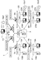
- FIG. 1 is an explanatory diagram showing the overall configuration of a relay communication system 1 according to an embodiment of the present invention.
- the relay communication system 1 includes a plurality of relay servers connected via an external server 2 arranged on a wide area network (WAN, wide area network) 3 such as the Internet, and these relays. And a client terminal connected to the server via a LAN.
- the relay server can communicate with client terminals, other relay servers, and client terminals connected to other relay servers.
- the client terminal can communicate with other relay servers and client terminals connected to other relay servers via a relay server connected via a LAN.
- this relay communication system 1 is used for remote maintenance and management.
- the terminals functioning as the relay server are the center terminal 5, the center spare terminal 6, the first maintenance terminal 7A, the second maintenance terminal 7B, the first maintenance terminal 9A, and the second maintenance terminal. 9B.
- the center terminal 5 and the center spare terminal 6 are provided in the call center.
- a call center is a base where an operator who responds to an inquiry from the owner of a maintenance target device is enrolled.
- the center terminal 5 manages the access right of the maintenance terminal (or the operator who performs maintenance) to the maintenance target terminal (has a management function).
- the center spare terminal 6 manages the access right on behalf of the center terminal 5 at the time of maintenance or failure of the center terminal 5.
- a center terminal operation terminal 11 as the client terminal is connected to the center terminal 5 and the center spare terminal 6 via a LAN 13.
- the global IP address of the center terminal 5 is (205.5.20.100), and the IP address of the center spare terminal 6 is (206.6.20.100).
- the center terminal 5 and the center spare terminal 6 in the present embodiment are configured to be able to switch ID (identification information). Then, of the center terminal 5 and the center spare terminal 6, the ID of a terminal that operates as a relay server with a management function is set as “Master@relaysystem.net”, and is used as a backup of the relay server with a management function (as a backup) The ID of the operating terminal is set as “Backup@relaysystem.net”. Therefore, in the example shown in FIG. 1, the center terminal 5 operates as a relay server with a management function, and the center spare terminal 6 operates as a spare relay server for the center terminal 5.
- the first maintenance target terminal 7A is provided at the installation destination of a device to be remotely maintained.
- a first maintenance target system 15A and a second maintenance target system 15B as the client terminals are connected to the first maintenance target terminal 7A via the LAN 17.
- the first maintenance target system 15A and the second maintenance target system 15B are a file server, a Web server, or the like that is a target of remote maintenance.
- the global IP address of the first maintenance target terminal 7A is (207.7.20.100).
- the ID of the first maintenance target terminal 7A is “Target1@relaysystem.net”.
- the second maintenance target terminal 7B is provided at the installation destination of the device to be remotely maintained.
- a third maintenance target system 19A and a fourth maintenance target system 19B as the client terminals are connected to the second maintenance target terminal 7B via the LAN 21.
- the third maintenance target system 19A and the fourth maintenance target system 19B are a file server, a Web server, or the like that is a target of remote maintenance.
- the global IP address of the second maintenance target terminal 7B is (217.7.20.100).
- the ID of the second maintenance target terminal 7B is “Target2@relaysystem.net”.
- the first maintenance terminal 9A is provided at a maintenance base where an operator who performs remote maintenance is enrolled.
- a first maintenance operation terminal 23A and a second maintenance operation terminal 23B as the client terminals are connected to the first maintenance terminal 9A via the LAN 25.
- the global IP address of the first maintenance terminal 9A is (209.9.20.100).
- the ID of the first maintenance terminal 9A is “Maintenance2@relaysystem.net”.
- the second maintenance terminal 9B is provided at a maintenance base where an operator who performs remote maintenance is enrolled.
- a third maintenance operation terminal 27A and a fourth maintenance operation terminal 27B as the client terminals are connected to the second maintenance terminal 9B via the LAN 29.
- the global IP address of the second maintenance terminal 9B is (2199.9.20.100).
- the ID of the second maintenance terminal 9B is “Maintenance1@relaysystem.net”.
- the operator can log in to the relay communication system 1 by operating the maintenance operation terminal and inputting the ID and password.
- the operator is not tied to a specific maintenance operation terminal, and can log in to the relay communication system 1 even when any maintenance operation terminal is used.
- the operator uses the maintenance operation terminal to perform remote maintenance of the maintenance target system within the range of access rights managed by the center terminal 5.
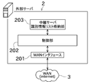
- FIG. 2 is a functional block diagram showing the configuration of the external server 2.
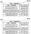
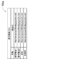
- FIG. 3 shows the contents of the relay server identification information list 203a.
- the external server 2 includes a WAN interface 201, a control unit 202, and a relay server identification information list storage unit 203 as main components.
- the WAN interface 201 is an interface that communicates with each device such as a relay server connected to the Internet using a global IP address.
- the relay server identification information list storage unit 203 stores a relay server identification information list 203a in which IDs of relay servers constituting the relay communication system 1 are associated with global IP addresses. .
- the identification of the center terminal 5, the center spare terminal 6, the first serviced terminal 7A, the second serviced terminal 7B, the first service terminal 9A, and the second service terminal 9B. Information is registered in association with the global IP address.
- the control unit 202 is a processing unit that controls various communications performed via the WAN interface 201, and controls communication processing according to a protocol such as TCP / IP, UDP, or SIP. For example, the control unit 202 receives information related to the identification of the relay server from each relay server and registers the information in the relay server identification information list 203a. In addition, the control unit 202 performs processing for relaying communication data such as various SIP methods or responses transmitted from the relay server to other relay servers.
- a protocol such as TCP / IP, UDP, or SIP.
- the control unit 202 receives information related to the identification of the relay server from each relay server and registers the information in the relay server identification information list 203a.
- the control unit 202 performs processing for relaying communication data such as various SIP methods or responses transmitted from the relay server to other relay servers.
- the center terminal 5 when transmitting a packet from the center terminal 5 to the first serviced terminal 7A, the center terminal 5 designates the “ID” of the first serviced terminal 7A as the transmission destination and sends the packet to the external server 2.
- the external server 2 reads the “global IP address” corresponding to the “ID” of the first maintenance target terminal 7A by referring to the relay server identification information list 203a. Then, the external server 2 transmits the packet received from the center terminal 5 with this “global IP address” as the transmission destination. Communication between relay servers is performed as described above. In the following, in order to simplify the description, the flow of communication through the external server 2 may be omitted.
- FIG. 4 is a functional block diagram showing the configuration of the center terminal 5.
- FIG. 5 to FIG. 9 are diagrams showing the contents stored in the center terminal 5.
- the center terminal 5 includes an interface 35, a database storage unit 33, a control unit 31, and a backup processing unit 37.
- the interface 35 can communicate with a device connected to the LAN 13 using a private IP address.
- the interface 35 can perform communication via the WAN 3 using a global IP address.
- the database storage unit 33 is configured by, for example, a nonvolatile storage unit.
- the database storage unit 33 includes an operator list storage unit 53, a maintenance terminal list storage unit 55, a to-be-maintained terminal list storage unit 57, and a connection job list storage unit 59.
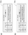
- the operator list 53a includes “ID”, “password”, and “login relay server”.
- ID an ID of an operator who can log in to the relay communication system 1 is described.
- password a password necessary for logging in to the relay communication system 1 using the ID described in the same row is described.
- login relay server when the operator has logged in to the relay communication system 1 using the ID described in the same row, the operator ID and the relay server used by the operator ( ID of the center terminal or maintenance terminal) is described. If the operator has not logged in to the relay communication system 1, the “login relay server” is blank.
- the maintenance terminal list storage unit 55 stores a maintenance terminal list 55a shown in FIG.
- the maintenance terminal list 55a is composed of “name” and “terminal ID” describing the maintenance terminals constituting the relay communication system 1.
- name a name given to the maintenance terminal is described. An appropriate name that is easy to understand, such as the installation location of the maintenance terminal (name of the maintenance base), can be given to this name.
- Terminal ID describes the ID of the maintenance terminal.
- the maintained terminal list storage unit 57 stores a maintained terminal list 57a shown in FIG.
- the to-be-maintained terminal list 57a includes “name” and “terminal ID” that describe the to-be-maintained terminals constituting the relay communication system 1.
- name a name given to the maintenance target terminal is described. This name can be given an easy-to-understand appropriate name such as the location (company name) of the terminal to be maintained.
- Terminal ID describes the ID of the maintenance target terminal.
- the connection job list storage unit 59 stores information on connection jobs.
- the connection job indicates a unit of maintenance work.
- the connection job is created by the center terminal 5 every time maintenance work is required for the maintenance target system, and is stored in the connection job list storage unit 59.
- the connection job list storage unit 59 stores a connection job list 59a including one or a plurality of connection jobs.
- the connection job list 59a includes “maintenance terminal ID”, “connection candidate ID”, and “job information” described for each connection job as shown in FIG.
- the “maintenance terminal ID” describes the ID of the maintenance target terminal connected to the same LAN as the maintenance target system requiring maintenance work.
- connection candidate ID an ID of an operator set as a candidate (connection candidate) that can be permitted to connect to the maintenance target terminal is described.
- connection candidate ID can describe the IDs of one or more operators.
- “Job information” describes the state of the current connection job (for example, which operator is executing the connection job). The connection job is deleted from the connection job list 59a when the maintenance work is completed.
- the first connection job is created for the second maintenance target terminal 7B, and the first operator Op1 and the third operator Op3 are set as the connection candidate operators.
- a second connection job is created for the first maintenance target terminal 7A, and the first operator Op1 is set as an operator as a connection candidate. I understand that.
- the first operator Op1 is executing the second connection job.
- the database storage unit 33 includes a log information storage unit (not shown), and stores information such as the time when the connection job was performed and the operator in charge.
- the control unit 31 includes a CPU, a RAM, a ROM, and the like, and can execute various processes by a program read from the ROM or the like. 4, the control unit 31 includes a login authentication unit 43, a connection job creation unit 45, an execution determination unit 47, a connection job list management unit 49, a candidate job list transmission unit 51, and permission information transmission. Part 52.
- the connection job creation unit 45 creates the connection job when a notification that a failure has occurred in the maintenance target system is received from the maintenance target terminal.
- the connection job list management unit 49 manages the connection job list 59a stored in the connection job list storage unit 59. Specifically, the connection job created by the connection job creation unit 45 is registered in the connection job list 59a, the job information in the connection job list 59a is updated, or the connection job is deleted from the connection job list 59a.
- the login authentication unit 43 collates the operator list 53a with the operator ID and password received from the maintenance terminal or the like, and determines whether or not the operator can log in. Further, the login authentication unit 43 determines whether or not login is possible based on whether or not the ID of the maintenance terminal that transmitted the operator ID or the like is included in the maintenance terminal list 55a.
- the candidate job list transmission unit 51 extracts a list of connection jobs (candidate job list) in which the operator is a connection candidate from the connection job list 59a, and selects a maintenance terminal. To the maintenance operation terminal. The operator selects a connection job desired to be executed from the candidate job list and notifies the center terminal 5 via the maintenance terminal.
- the execution determining unit 47 reads the job information of the connection job notified from the operator from the connection job list 59a, and based on this job information (for example, whether there is another operator who has already executed the connection job). To determine whether to permit execution of the connection job.
- the permission information transmission unit 52 transmits the determination result of the execution determination unit 47 (whether or not to permit execution of the connection job) to the maintenance operation terminal via the maintenance terminal and notifies the operator.
- the backup processing unit 37 includes an identification information storage unit 111, a switching control unit 112, an identification information registration unit 113, and a stored information transmission unit 114.
- the identification information storage unit 111 stores a master ID (master identification information, Master@relaysystem.net) and a backup ID (backup identification information, Backup@relaysystem.net).
- the switching control unit 112 can switch the center terminal 5 from the master to the backup, and can switch from the backup to the master. Specifically, the switching control unit 112 switches the setting of the center terminal 5 from the backup to the master by switching the ID of the center terminal 5 from the backup ID to the master ID. On the other hand, the switching control unit 112 switches the setting of the center terminal 5 from the master to the backup by switching the ID of the center terminal 5 from the master ID to the backup ID.
- the identification information registration unit 113 performs processing for registering the ID of the center terminal 5 and the global IP address of the center terminal 5 in the external server 2 after the setting of the center terminal 5 is switched by the switching control unit 112. Specifically, when the setting of the center terminal 5 is switched from backup to master, the identification information registration unit 113 displays the master ID and the global IP address of the center terminal 5 in the relay server identification information list of the external server 2. Register in 203a. On the other hand, the identification information registration unit 113 registers the backup ID and the global IP address of the center terminal 5 in the relay server identification information list 203a of the external server 2 when the setting of the center terminal 5 is switched from the master to the backup. To do.
- the storage information transmission unit 114 performs processing for transmitting the storage contents (management information) of the database storage unit 33 to another center terminal (that is, the center spare terminal 6). For example, by transmitting management information from the center terminal 5 operating as a master to the center spare terminal 6 operating as a backup, a copy of the management information stored in the center terminal 5 operating as a master (hereinafter referred to as spare data). May be stored in the center spare terminal 6.
- the center terminal 5 includes a preliminary data creation switch (operation unit) 120 on the front surface of the apparatus.
- the storage information transmission unit 114 transmits management information by pressing the preliminary data creation switch 120 by an operator or the like.
- preliminary data can be flexibly created and updated in accordance with the situation, for example, preliminary data is created after the storage content of the database storage unit 33 is largely changed.
- FIG. 10 is a functional block diagram showing the configuration of the first maintenance terminal 9A. Since the configuration of the first maintenance terminal 9A and the second maintenance terminal 9B is the same, the configuration of the first maintenance terminal 9A will be described as a representative. As shown in FIG. 10, the first maintenance terminal 9 ⁇ / b> A includes an interface 65, a control unit 61, and a database storage unit 63.
- the interface 65 can communicate with a device connected to the LAN 25 using a private IP address.
- the interface 65 can perform communication via the WAN 3 using a global IP address.
- the control unit 61 includes a CPU, a RAM, a ROM, and the like, and can execute various processes by a program read from the ROM or the like. As shown in FIG. 10, the control unit 61 includes a routing session establishment unit 71, a routing control unit 73, a login information transmission unit 75, and a selected job notification unit 77.
- the routing session establishment unit 71 establishes a routing session between the first maintenance terminal 9A and the first maintenance target terminal 7A or the second maintenance target terminal 7B.
- the routing session is a media session used for routing communication packets transferred between a device connected to the LAN 25 and a device connected to a LAN (LAN 17 or LAN 21) where the maintenance target system is installed.
- the routing control unit 73 uses this routing session to perform routing control of communication packets with devices connected to other LANs.
- the login information transmission unit 75 transmits the operator ID and password (hereinafter referred to as login information) received from the first maintenance operation terminal 23A or the second maintenance operation terminal 23B to the center terminal 5.
- the selected job notification unit 77 transmits the connection job selected from the candidate job list by the operator to the center terminal 5.
- the database storage unit 63 includes a center terminal information storage unit 81. Master identification information is stored in the center terminal information storage unit 81.
- the first maintenance terminal 9A refers to the stored contents of the center terminal information storage unit 81, and accesses the center terminal operating as a master in order to notify, for example, a connection job selected from the candidate job list. Can do.
- FIG. 11 is a functional block diagram showing the configuration of the first maintenance target terminal 7A. Since the configuration of the first serviced terminal 7A and the second serviced terminal 7B is the same, the configuration of the first serviced terminal 7A will be described as a representative. As illustrated in FIG. 11, the first maintenance target terminal 7 ⁇ / b> A includes an interface 95, a control unit 91, and a database storage unit 93.
- the interface 95 can communicate with a device connected to the LAN 17 using a private IP address. Further, the interface 95 can perform communication via the WAN 3 by using a global IP address.
- the control unit 91 includes a CPU, a RAM, a ROM, and the like, and can execute various processes by a program read from the ROM. As shown in FIG. 11, the control unit 91 includes a routing session establishment unit 101 and a routing control unit 103.
- the routing session establishment unit 101 establishes a routing session between the first maintenance target terminal 7A and the first maintenance terminal 9A or the second maintenance terminal 9B.
- the routing control unit 103 performs routing control of communication packets with devices connected to other LANs using this routing session.
- the database storage unit 93 includes a center terminal information storage unit 105.
- the center terminal information storage unit 105 stores master identification information.
- the first maintenance target terminal 7A can access the center terminal that operates as a master in order to notify that maintenance work is necessary, for example. .
- the second operator Op2 has logged in to the relay communication system 1 using the center terminal 5 as a login relay server
- the third operator Op3 has logged in to the relay communication system 1 using the second maintenance target terminal 7B as a login relay server.
- connection job is created every time maintenance work is required on the maintenance target system.
- a case where maintenance work is required for the first maintenance target system 15A will be considered.
- the fact is notified to the first maintenance target terminal 7A.
- the first maintenance target terminal 7A receives the fact that a failure has occurred (sequence number 1 in FIG. 12), it notifies the center terminal 5 to that effect and requests the creation of a connection job (sequence number 2).
- the center terminal 5 transfers this notification and request to the center terminal operation terminal 11 and notifies the second operator Op2 (sequence number 3).
- the second operator Op2 selects an operator that preferably performs maintenance based on the content of the failure, the name of the maintenance target terminal, and the like.
- the center terminal 5 (connection job creation unit 45) creates a connection job (second connection job) (sequence number 4).
- the center terminal 5 (connection job list management unit 49) registers the created second connection job in the connection job list 59a (sequence number 5). That is, in the connection job list 59a, “maintenance terminal ID” describes the ID of the first maintenance target terminal 7A, and “connection candidate ID” describes the ID of the first operator Op1 (FIG. 8 ( see b)).
- connection job is created as described above. If it is necessary to cause the first operator Op1 to perform maintenance work as soon as possible, the first operator Op1 may be notified immediately after creating the connection job.
- the notification that the connection job has been created can be performed in various ways. For example, when the instant message service is operated on the relay communication system 1 and the first operator Op1 has logged in to the relay communication system 1, The second operator Op2 can make the notification using the instant message service. If the first operator Op1 is not logged in to the relay communication system 1, it may be notified by appropriate means such as a telephone.
- the first operator Op1 operates the first maintenance operation terminal 23A to make a login request to the relay communication system 1 using the first maintenance terminal 9A as a login relay server, processing performed in the relay communication system 1 Will be explained.
- the first operator Op1 is requested to input login information (ID and password).
- the first operator Op1 operates the first maintenance operation terminal 23A to input the ID (Op1) and the password (abc), and confirms the input contents, whereby the login information is transmitted to the first maintenance terminal 9A.
- the first maintenance terminal 9A receives the login request (sequence number 11 in FIG. 13), and transmits the received login information to the center terminal 5 (sequence number 12).
- the center terminal 5 (login authentication unit 43) that has received this login information determines whether or not login is possible. Specifically, the login authentication unit 43 determines whether or not the input ID and password are registered in the operator list 53a (sequence number 13), and the first maintenance terminal 9A that transmitted the login information serves as the maintenance terminal. It is determined whether or not it is registered in the list 55a (sequence number 14).
- the ID and password input above are registered in the operator list 53a. Further, as shown in FIG. 6, the first maintenance terminal 9A is registered in the maintenance terminal list 55a. Therefore, the login authentication unit 43 permits the login of the first operator Op1. Then, the center terminal 5 updates the contents of the operator list 53a (sequence number 15). Specifically, the ID of the first operator Op1 and the ID of the first maintenance terminal 9A are described in the “login relay server” corresponding to the first operator Op1 in the operator list 53a (from FIG. 5A). The operator list 53a is updated as shown in FIG. 5B). Then, the center terminal 5 notifies the first maintenance terminal 9A of successful login (sequence number 16). If the center terminal 5 fails to authenticate the terminal ID or the login information, the center terminal 5 notifies the first maintenance terminal 9A of the login failure.
- the first maintenance terminal 9A transfers the login success notification received from the center terminal 5 to the first maintenance operation terminal 23A and notifies the first operator Op1 of the login success (sequence number 17). Then, the first maintenance terminal 9A requests the center terminal 5 for the candidate job list (a list of connection jobs in which the logged-in first operator Op1 is a connection candidate) (sequence number 18).
- the center terminal 5 Upon receiving this notification, the center terminal 5 (candidate job list transmission unit 51) extracts a connection job in which the first operator Op1 is a connection candidate from the connection jobs stored in the connection job list 59a, and obtains a candidate job. A list is created (sequence number 19). As shown in FIG. 8B, since both the first connection job and the second connection job described in the connection job list 59a have the first operator Op1 as a connection candidate, One connection job and second connection job are described. Then, candidate job list transmission unit 51 transmits the created candidate job list to first maintenance terminal 9A (sequence number 20). When there is no connection job for which the first operator Op1 is a connection candidate, the center terminal 5 transmits a message to that effect to the first maintenance terminal 9A.
- the first maintenance terminal 9A transfers the candidate job list received from the center terminal 5 to the first maintenance operation terminal 23A and notifies the first operator Op1 (sequence number 21). Specifically, the first maintenance operation terminal 23A displays the candidate job list on its own display. Accordingly, the first operator Op1 can know a list of connection jobs that can be executed by the first operator Op1.
- the first operator Op1 can log in to the relay communication system 1 from the first maintenance terminal 9A by operating the second maintenance operation terminal 23B. Furthermore, it is possible to log in to the relay communication system 1 from the second maintenance terminal 9B by operating the third maintenance operation terminal 27A or the fourth maintenance operation terminal 27B.
- the first maintenance terminal 9A accepts the selection of the connection job (sequence number 31 in FIG. 14) and notifies the selection content of the first operator Op1 to the center terminal 5 together with the ID of the first operator Op1 (sequence number 32). ).
- the center terminal 5 (execution determination unit 47) reads job information of the second connection job, which is the corresponding connection job, from the connection job list 59a (sequence number 33). Then, the execution determination unit 47 determines whether the second connection job is being executed or is being prepared for execution based on the read job information (sequence number 34). As shown in FIG. 8B, since the job information of the second connection job is blank, the connection job is neither being executed nor being prepared for execution. Accordingly, the execution determination unit 47 permits the first connection Op 1 to execute the second connection job. Thereafter, the connection job list management unit 49 describes “preparing for execution” in the job information of the second connection job in the connection job list 59a (sequence number 35).
- the second operator Op2 of the call center can know that the connection work for the second connection job has started. At this time, the execution of the second connection job by another operator can be excluded. Then, the center terminal 5 (permission information transmission unit 52) notifies the first maintenance terminal 9A that the execution of the corresponding connection job is permitted (sequence number 36). When the center terminal 5 does not permit execution of the connection job, the center terminal 5 notifies the first maintenance terminal 9A to that effect.
- the first maintenance terminal 9A transfers a notification that the execution of the connection job is permitted to the first maintenance operation terminal 23A and notifies the first operator Op1 (sequence number 37). Then, the first maintenance terminal 9A (routing session establishment unit 71) makes a routing session establishment request to the first maintenance target terminal 7A that is the maintenance destination of the corresponding connection job (sequence number 38). In response to this request, first maintenance target terminal 7A (routing session establishing unit 101) returns an OK response as access permission (sequence number 39). As a result, a media session is established between the first maintenance terminal 9A and the first maintenance target terminal 7A.
- the first maintenance terminal 9A and the first maintenance target terminal 7A exchange the network addresses of the LAN 17 and the LAN 25 that are routing targets. This enables communication between the first maintenance operation terminal 23A and the first maintenance target system 15A or the second maintenance target system 15B via the routing session. Then, the first maintenance terminal 9A transmits to the first maintenance operation terminal 23A that the routing session has been established and notifies the first operator Op1 (sequence number 40). Furthermore, the first maintenance terminal 9A notifies the center terminal 5 that a routing session has been established (sequence number 41).
- the center terminal 5 (connection job list management unit 49) writes “Op1 in progress” in the job information of the second connection job in the connection job list 59a as shown in FIG. 8C. (Sequence number 42). Thereby, the second operator Op2 of the call center can know that the second connection job is started by the first operator Op1.
- the first maintenance terminal 9A performs maintenance work on the system (first maintenance target system 15A) requiring maintenance via the routing session established with the first maintenance target terminal 7A (sequence number 43). ). Specifically, the first operator Op1 can perform maintenance work such as grasping the state of the first maintenance target system 15A and updating the software by operating the first maintenance operation terminal 23A.
- 1st operator Op1 notifies the completion of the said maintenance work to the 1st to-be-maintained terminal 7A via the 1st maintenance terminal 9A after the maintenance work is completed (sequence number 51 of FIG. 15). Further, the first operator Op1 notifies the completion of the maintenance work also to the center terminal 5 via the first maintenance terminal 9A (sequence number 52).
- connection job list management unit 49 Upon receiving this notification, the center terminal 5 (connection job list management unit 49) registers the completion of the maintenance work in the job information of the second connection job (sequence number 53), and sends the second connection job from the connection job list 59a. Delete (sequence number 54).
- the first maintenance terminal 9A requests the candidate job list from the center terminal 5 again, and a new maintenance operation by the first operator Op1 is performed through the same processing.
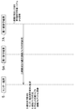
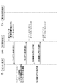
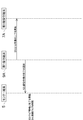
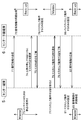
- FIG. 16 is a sequence diagram showing processing performed between the center terminal 5 and the center spare terminal 6.
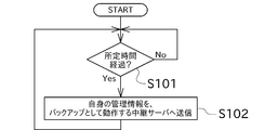
- FIG. 17 is a flowchart showing a process in which the center terminal 5 causes the center spare terminal 6 to create spare data.
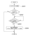
- FIG. 18 is a flowchart showing processing performed immediately after the center spare terminal 6 is switched from the master to the backup.
- the center terminal 5 that operates as a master performs a process of synchronizing management information with the center spare terminal 6 that operates as a backup. Specifically, the center terminal 5 performs the process shown in the flowchart of FIG. That is, the center terminal 5 transmits its management information to the center spare terminal 6 every time a predetermined time elapses (S101) (S102, sequence number 71).
- the center spare terminal 6 performs a process (synchronization process) for replacing the management information stored therein with the management information received from the center terminal 5 (sequence number 72). In this way, the management information of the center terminal 5 that operates as a master can be stored in the center spare terminal 6 that operates as a backup.
- the center spare terminal 6 can be operated as a master in a state where management information is taken over to some extent.
- the center terminal 5 accepts that it stops by this notification (sequence number 73). Then, the center terminal 5 requests the center spare terminal 6 to operate as a master instead of itself, together with a notification that it stops (sequence number 74).
- the center terminal 5 also notifies the external server 2 that it will stop. As a result, the global IP address associated with the master ID that is the ID of the center terminal 5 at the present time is deleted in the relay server identification information list 203 a stored in the external server 2.
- the center spare terminal 6 notifies the external server 2 that it operates as a master.
- the global IP address associated with the backup ID which is the current ID, is deleted from the relay server identification information list 203a stored in the external server 2.
- the center spare terminal 6 is restarted, and at this timing, the switching control unit 112 switches the ID of the center spare terminal 6 from the backup ID to the master ID.
- the identification information registration unit 113 registers the identification information in the external server 2.
- the identification information registration unit 113 determines the master ID (Master@relaysystem.net), which is the ID of the center spare terminal 6 at the current time, and the global IP address (206.6.20.0100) of the center spare terminal 6. ) To the external server 2. Based on this information, the external server 2 associates the master ID with the global IP address of the center spare terminal 6 and registers it in the relay server identification information list 203a (see the chain line in FIG. 3B). Thus, the setting for operating as a master is completed.
- Master@relaysystem.net the ID of the center spare terminal 6 at the current time
- the global IP address 206.6.20.0100
- FIG. 3A which is the relay server identification information list 203a when the center terminal 5 is operating as a master
- the global IP address of the center terminal 5 is associated with the master ID.
- FIG. 3B which is the relay server identification information list 203a when the center spare terminal 6 operates as a master
- the global IP address of the center spare terminal 6 is associated with the master ID. Therefore, even if the maintenance terminal and the maintenance target terminal change from the center terminal 5 to the center spare terminal 6, the maintenance terminal and the maintenance target terminal can communicate with the center spare terminal 6 functioning as the master without any problem without changing the designation of the transmission destination. it can.
- the second operator Op2 notifies the center terminal 5 that the center terminal 5 is to be operated again as a master.
- the center terminal 5 Upon receiving this notification (sequence number 77), the center terminal 5 notifies the center standby terminal 6 that it operates as a master (sequence number 78).
- the center spare terminal 6 replies that this notification has been accepted (sequence number 79), and makes settings for operating as a backup (sequence number 80).
- the center spare terminal 6 notifies the external server 2 and deletes the global IP address corresponding to the master ID in the relay server identification information list 203a.
- the center spare terminal 6 is restarted, and at this timing, the switching control unit 112 switches the ID of the center spare terminal 6 from the master ID to the backup ID.
- the identification information registration unit 113 notifies the external server 2 and, as a result, the global IP address of the center spare terminal 6 is associated with the backup ID of the relay server identification information list 203a.
- the center terminal 5 receives the response (the sequence number 79) from the center spare terminal 6 and performs settings for starting as a master (sequence number 81). Since the processing performed here is equivalent to the sequence number 76, detailed description thereof will be omitted, but its own ID is set as the master ID, and in the relay server identification information list 203a, the global IP address associated with the master ID is set. Register your own address.
- the center spare terminal 6 when the center spare terminal 6 is activated as a backup, the processing shown in FIG. 18 is performed. That is, the center spare terminal 6 is activated as a backup (S201), and then determines whether or not the master has switched to the backup (S202). In this description, since the center spare terminal 6 has been switched from the master to the backup, the center spare terminal 6 determines whether or not the center terminal 5 operating as the master has been activated (S203). If the center terminal 5 is not activated, the management terminal transmits its management information to the center terminal 5 after waiting for completion of activation (S204, sequence number 82).
- the center terminal 5 that has received this management information performs management information synchronization processing (sequence number 83).
- the center terminal 5 can be operated as a master in a state in which the change is reflected.
- the management information does not need to be transmitted because it has not operated as the master until immediately before.
- the spare terminal 6 does not perform any particular processing.
- the center standby terminal 6 of the present embodiment includes the database storage unit 33, the switching control unit 112, the identification information storage unit 111, the identification information registration unit 113, the storage information transmission unit 114, Is provided.
- the database storage unit 33 stores information for managing the relay communication system 1 including relay servers that can communicate with each other via the external server 2.
- the switching control unit 112 can switch between operating as a master managing the relay communication system 1 and operating as a backup of the master.
- the identification information storage unit 111 stores master identification information, which is identification information set for itself when operating as a master, and backup identification information, which is identification information set for itself when operating as a backup.
- the identification information registration unit 113 registers the master identification information and its own network information in the external server 2 when operating as a master, and stores the backup identification information and its own network information when operating as a backup. Register in the external server 2.
- the storage information transmission unit 114 transmits the contents of the database storage unit 33 to the center terminal 5 operating as a master when switching from a state operating as a master to a state operating as a backup.
- the storage information transmitting unit 114 transmits the contents of the database storage unit 33 to the center spare terminal 6 operating as a backup.
- the contents stored in the database storage unit 33 of the center terminal 5 can be stored in the center spare terminal 6. Therefore, even if a sudden failure occurs in the center terminal 5, the center spare terminal 6 can be operated as a master while (at least) the contents stored in the database storage unit 33 are taken over to some extent.
- transmission of the storage content of the database storage unit 33 by the storage information transmission unit 114 when operating as a master is automatically performed at set time intervals.
- the center terminal 5 of the present embodiment includes a preliminary data creation switch 120 that can be operated to cause the stored information transmission unit 114 to transmit the stored contents of the database storage unit 33 when operating as a master.
- the spare center terminal 6 operating as a backup is spare data for switching to the master (content stored in the database storage unit 33 of the center terminal 5). Copy). Therefore, for example, by operating the preliminary data creation switch 120 at the timing when the stored contents of the database storage unit 33 are largely changed in the center terminal 5 operating as a master, the preliminary data is flexibly updated according to the situation. be able to.
- the center spare terminal 6 is connected to the same LAN 13 as the center terminal 5, but the center spare terminal 6 may be arranged on a different LAN. In this case, even if a communication failure occurs in the LAN 13, the center spare terminal 6 can be operated as a master instead of the center terminal 5.
- connection job can also be created from the maintenance operator side. For example, when a regular maintenance is scheduled, an operator in charge of the regular maintenance makes a connection job creation request to the center terminal at the maintenance timing, thereby creating a connection job.
- the number of maintenance target terminals and maintenance terminals constituting the relay communication system 1 is not limited to the above embodiment, and may be one or three or more, respectively.
- the number of maintenance target systems connected to the maintenance target terminal and the number of maintenance operation terminals connected to the maintenance terminal are not limited to the above embodiment, and may be one each, or three or more. There may be.
- the first maintenance terminal 9A and the second maintenance terminal 9B may be a memory that is detachably attached to a personal computer and an application stored in the memory.
- the operator list 53a, the maintenance terminal list 55a, the maintenance target terminal list 57a, and the connection job list 59a can be stored in an appropriate format (for example, XML format).
- the center terminal 5 and the center spare terminal 6 when the center terminal 5 and the center spare terminal 6 operate as masters, the center terminal 5 and the center spare terminal 6 are configured to transmit management information to a terminal that operates as a backup every predetermined time or at a timing when the spare data creation switch 120 is pressed. is there.
- the timing at which the management information is transmitted is not limited to the above.
- the management information may be transmitted according to a predetermined schedule.
- an external server used for communication between each relay server may be installed on the Internet, and a communication may be performed by exhibiting a function as a SIP (Session Initiation Protocol) server. .
- SIP Session Initiation Protocol
Landscapes
- Engineering & Computer Science (AREA)
- Theoretical Computer Science (AREA)
- General Engineering & Computer Science (AREA)
- Computer Security & Cryptography (AREA)
- General Physics & Mathematics (AREA)
- Physics & Mathematics (AREA)
- Quality & Reliability (AREA)
- Computer Networks & Wireless Communication (AREA)
- Signal Processing (AREA)
- Computer Hardware Design (AREA)
- Computing Systems (AREA)
- Data Exchanges In Wide-Area Networks (AREA)
- Telephonic Communication Services (AREA)
- Small-Scale Networks (AREA)
- Information Transfer Between Computers (AREA)
Abstract
センター予備端末(中継サーバ)は、管理情報を格納する。センター予備端末(6)は、マスタとして動作するかバックアップとして動作するかを切替可能である。センター予備端末(6)は、マスタとして動作する場合には、マスタ識別情報と自身のネットワーク情報とを外部サーバに登録し、バックアップとして動作する場合には、バックアップ識別情報と自身のネットワーク情報とを外部サーバに登録する。センター予備端末(6)は、マスタとして動作する状態からバックアップとして動作する状態に切り替わった場合に、マスタとして動作するセンター端末(5)へ管理情報を送信する。
Description
本発明は、主として、異なるLAN(Local Area Network)に接続されている端末間の通信を可能とする中継サーバに関する。
従来から、仮想プライベートネットワーク(Virtual Private Network,VPN)と呼ばれる通信技術が知られている。このVPNは、例えば、地域ごとに設けられた複数の拠点のLANに接続された端末同士でインターネットを介して通信する用途に用いられている。前記VPNを利用すれば、遠隔地にある他のLANを、あたかも直接接続されているネットワークであるかのように使用することができる。VPNは、例えば、他の拠点に設けられた端末を遠隔保守する用途に用いられる。保守対象の端末は、遠隔地にある他のLANに接続された機器からリモートメンテナンス等を受けることができる。
特許文献1は、この種のネットワークを介した管理システムを開示する。この管理システムは、ビルオーナ、設備保守会社、及び電気設備メーカーに跨る形で構築されている。ビルオーナは、自身が保有するビルに、電気設備及びこれを制御するための運転制御管理装置を設置している。この運転制御管理装置は、インターネット等のネットワークを介してアクセス可能に構成されている。設備保守会社は、ビルオーナから電気設備の管理を委託され、運転制御管理装置にアクセスする許可を電気設備メーカーから得ている。従って、設備保守会社は、インターネット等のネットワークを介して遠隔地から電気設備に対する保守作業を行うことができる。
しかし、上記特許文献1のように、保守側の機器から被保守側の機器へのアクセスを管理側の機器で一括して管理するシステムでは、管理側の機器が停止してしまった場合に、管理システム自体が機能しなくなる。そのため、管理側の機器にバックアップ機を設けて多重化することが考えられる。
しかし、バックアップ機を設ける構成では、管理側の機器が有する膨大な(又は更新頻度の高い)情報について、バックアップ機のデータをマスタと同期させる処理が必要となる。また、マスタとなる機器に不具合が発生してバックアップ機により管理システムを管理する場合、管理対象の機器がデータを新しいマスタへ送信できるようにするために、当該管理対象の機器の設定を変更する必要がある。この設定の変更は、管理システムの規模が大きくなると特に煩雑な作業となり、マスタとバックアップとをスムーズに交替させる観点から改善が望まれていた。
本発明は以上の事情に鑑みてされたものであり、その目的は、複数の中継サーバによって構築された中継通信システムに用いられる中継サーバにおいて、管理側の中継サーバが停止した場合でも、管理対象の中継サーバの設定を変更することなく、中継通信システムの運用を継続可能な構成を提供することにある。
本発明の解決しようとする課題は以上の如くであり、次にこの課題を解決するための手段とその効果を説明する。
本発明の第1の観点によれば、以下の構成の中継サーバが提供される。即ち、この中継サーバは、データベース格納部と、切替制御部と、識別情報記憶部と、識別情報登録部と、格納情報送信部と、を備える。前記データベース格納部は、識別情報とネットワーク情報とを対応付けて記憶する外部サーバを介して互いに通信可能な中継サーバを含んで構成される中継通信システムに関し、当該中継通信システムを管理するための情報を格納する。前記切替制御部は、前記中継通信システムを管理するマスタとして動作するか、当該マスタのバックアップとして動作するかを切替可能である。前記識別情報記憶部は、マスタとして動作する場合に自身に設定する識別情報であるマスタ識別情報と、バックアップとして動作する場合に自身に設定する識別情報であるバックアップ識別情報と、を記憶する。前記識別情報登録部は、マスタとして動作する場合には、前記マスタ識別情報と自身のネットワーク情報とを前記外部サーバに登録し、バックアップとして動作する場合には、前記バックアップ識別情報と自身のネットワーク情報とを前記外部サーバに登録する。前記格納情報送信部は、マスタとして動作する状態からバックアップとして動作する状態に切り替わった場合に、マスタとして動作する他の前記中継サーバへ前記データベース格納部の内容を送信する。
これにより、上記の中継サーバを複数用いて、そのうちの1つをマスタとして動作させ、その他をバックアップとして動作させることで、管理機能付き中継サーバのバックアップ運用が可能となる。また、どの中継サーバがマスタとして動作する場合であっても、マスタとして動作する中継サーバには、常にマスタ識別情報が設定される。従って、マスタとして動作する中継サーバが切り替わった場合でも、管理対象の中継サーバは、特に設定を変更することなく、マスタとして動作する中継サーバと通信を行うことができる。従って、マスタとして動作する中継サーバの切替えをスムーズに行うことができる。
前記の中継サーバにおいては、マスタとして動作する場合、前記格納情報送信部は、バックアップとして動作する他の前記中継サーバへ前記データベース格納部の内容を送信することが好ましい。
これにより、マスタとして動作する中継サーバのデータベース格納部の格納内容を、バックアップとして動作する中継サーバに保存しておくことができる。従って、マスタとして動作する中継サーバに突発的な障害が発生した場合であっても、データベース格納部の格納内容を(少なくとも)ある程度引き継いだ状態で、他の中継サーバをマスタとして動作させることができる。
前記の中継サーバにおいては、マスタとして動作する場合、前記格納情報送信部は、設定された時間毎に自動で、前記データベース格納部の格納内容を送信することが好ましい。
これにより、ユーザの手間を低減しつつ、バックアップとして動作する他の前記中継サーバは、マスタに切り替わったときのための予備データを定期的に更新することができる。
前記の中継サーバにおいては、操作部を備え、マスタとして動作する場合、前記格納情報送信部は、前記操作部が操作されたタイミングで、前記データベース格納部の格納内容を送信することが好ましい。
これにより、バックアップとして動作する他の前記中継サーバは、操作部が操作された時点で、マスタに切り替わったときのための予備データを更新することができる。従って、例えば、マスタとして動作する中継サーバにおいてデータベース格納部の格納内容が大きく変更されたタイミングで操作部を操作する等、予備データの作成及び更新を状況に合わせて柔軟に行うことができる。
本発明の第2の観点によれば、以下の構成の中継通信システムが提供される。即ち、この中継通信システムは、複数の管理機能付き中継サーバと、複数の管理対象の中継サーバと、を含んで構成される。前記管理対象の中継サーバは、識別情報とネットワーク情報とを対応付けて記憶する外部サーバを介して前記管理機能付き中継サーバと通信可能である。前記管理機能付き中継サーバは、データベース格納部と、切替制御部と、識別情報記憶部と、識別情報登録部と、格納情報送信部と、を備える。前記データベース格納部は、前記管理対象の中継サーバを管理するための情報を格納する。前記切替制御部は、前記管理対象の中継サーバの管理を行うマスタとして動作するか、当該マスタのバックアップとして動作するかを切替可能である。前記識別情報記憶部は、マスタとして動作する場合に自身に設定する識別情報であるマスタ識別情報と、バックアップとして動作する場合に自身に設定する識別情報であるバックアップ識別情報と、を記憶する。前記識別情報登録部は、マスタとして動作する場合には、前記マスタ識別情報と自身のネットワーク情報とを前記外部サーバに登録し、バックアップとして動作する場合には、前記バックアップ識別情報と自身のネットワーク情報とを前記外部サーバに登録する。前記格納情報送信部は、マスタとして動作する状態からバックアップとして動作する状態に切り替わった場合に、マスタとして動作する他の前記管理機能付き中継サーバに前記データベース格納部の内容を送信する。なお、前記管理機能付き中継サーバのうち1台がマスタとして動作して、他の前記管理機能付き中継サーバがバックアップとして動作する。
上記の構成では、どの中継サーバがマスタとして動作する場合であっても、マスタとして動作する中継サーバには、常にマスタ識別情報が設定される。従って、管理対象の中継サーバは、同一の識別情報を送信先として指定するだけで、マスタとして動作する中継サーバにパケットを送信することができる。従って、マスタとバックアップが切り替わった場合においても管理対象の中継サーバの設定変更が不要となるので、マスタとバックアップの切替えをスムーズに行うことができる。
次に、図面を参照して本発明の実施の形態を説明する。図1は、本発明の一実施形態に係る中継通信システム1の全体構成を示す説明図である。
図1に示すように、中継通信システム1は、インターネット等のWide Area Network(WAN、広域通信網)3上に配置された外部サーバ2を介して接続された複数の中継サーバと、これらの中継サーバにLANを介して接続されるクライアント端末と、で構成されている。中継サーバは、クライアント端末、他の中継サーバ及び他の中継サーバに接続されるクライアント端末と通信可能である。クライアント端末は、LANで接続された中継サーバを介して、他の中継サーバ及び他の中継サーバに接続されるクライアント端末と通信可能である。
本実施形態では、この中継通信システム1を用いて、遠隔保守及びその管理が行われている。中継通信システム1において、前記中継サーバとして機能する端末は、センター端末5、センター予備端末6、第1被保守端末7A、第2被保守端末7B、第1保守端末9A、及び、第2保守端末9Bである。
センター端末5及びセンター予備端末6は、コールセンターに設けられている。コールセンターとは、保守対象の機器の所有者からの問い合わせに対応するオペレータが在籍する拠点である。また、センター端末5は、保守端末(又は保守を行うオペレータ)の被保守端末に対するアクセス権を管理している(管理機能を有している)。センター予備端末6は、センター端末5のメンテナンス時又は故障時に、センター端末5に代わって上記アクセス権を管理する。センター端末5及びセンター予備端末6には、前記クライアント端末としてのセンター端末操作端末11がLAN13を介して接続されている。なお、センター端末5のグローバルIPアドレスは、(205.5.20.100)であり、センター予備端末6のIPアドレスは、(206.6.20.100)である。本実施形態におけるセンター端末5及びセンター予備端末6は、ID(識別情報)を切替可能に構成されている。そして、センター端末5及びセンター予備端末6のうち、管理機能付きの中継サーバとして動作する端末のIDを「Master@relaysystem.net」と設定し、管理機能付きの中継サーバの予備として(バックアップとして)動作する端末のIDを「Backup@relaysystem.net」と設定している。そのため、図1に示す例では、センター端末5が管理機能付きの中継サーバとして動作し、センター予備端末6がセンター端末5の予備の中継サーバとして動作する。
第1被保守端末7Aは、遠隔保守の対象となる機器の設置先に設けられている。第1被保守端末7Aには、LAN17を介して、前記クライアント端末としての第1被保守対象システム15A及び第2被保守対象システム15Bが接続されている。第1被保守対象システム15A及び第2被保守対象システム15Bは、遠隔保守の対象となるファイルサーバ又はWebサーバ等である。図1に示すように、第1被保守端末7AのグローバルIPアドレスは、(207.7.20.100)である。また、第1被保守端末7AのIDは、「Target1@relaysystem.net」である。
第2被保守端末7Bは、遠隔保守の対象となる機器の設置先に設けられている。第2被保守端末7Bには、LAN21を介して、前記クライアント端末としての第3被保守対象システム19A及び第4被保守対象システム19Bが接続されている。第3被保守対象システム19A及び第4被保守対象システム19Bは、遠隔保守の対象となるファイルサーバ又はWebサーバ等である。図1に示すように、第2被保守端末7BのグローバルIPアドレスは、(217.7.20.100)である。また、第2被保守端末7BのIDは、「Target2@relaysystem.net」である。
第1保守端末9Aは、遠隔保守を行うオペレータが在籍する保守拠点に設けられている。第1保守端末9Aには、LAN25を介して、前記クライアント端末としての第1保守操作端末23A及び第2保守操作端末23Bが接続されている。図1に示すように、第1保守端末9AのグローバルIPアドレスは、(209.9.20.100)である。また、第1保守端末9AのIDは、「Maintenance2@relaysystem.net」である。
第2保守端末9Bは、遠隔保守を行うオペレータが在籍する保守拠点に設けられている。第2保守端末9Bには、LAN29を介して、前記クライアント端末としての第3保守操作端末27A及び第4保守操作端末27Bが接続されている。図1に示すように、第2保守端末9BのグローバルIPアドレスは、(219.9.20.100)である。また、第2保守端末9BのIDは、「Maintenance1@relaysystem.net」である。
保守拠点に在籍するオペレータが保守作業を行うためには、中継通信システム1にログインすることが必要である。オペレータは、保守操作端末を操作してID及びパスワードを入力することにより、中継通信システム1にログインすることができる。本実施形態の中継通信システム1では、オペレータは特定の保守操作端末に結び付けられておらず、何れの保守操作端末を使用した場合であっても中継通信システム1にログインすることができる。オペレータは、中継通信システム1へのログイン後に、前記保守操作端末を使用して、前記センター端末5が管理するアクセス権の範囲で、前記保守対象システムの遠隔保守を行う。
次に、図2及び図3を参照して、外部サーバ2について説明する。図2は、外部サーバ2の構成を示す機能ブロック図である。図3は、中継サーバ識別情報リスト203aの内容を示す図である。外部サーバ2は、図2に示すように、WANインタフェース201と、制御部202と、中継サーバ識別情報リスト格納部203と、を主要な構成として備えている。
WANインタフェース201は、グローバルIPアドレスを使用して、インターネットに接続された中継サーバ等の各装置と通信を行うインタフェースである。
中継サーバ識別情報リスト格納部203は、図3(a)に示すように、中継通信システム1を構成する中継サーバのIDをグローバルIPアドレスと対応付けた中継サーバ識別情報リスト203aを保存している。本実施形態の中継サーバ識別情報リスト203aにおいては、センター端末5、センター予備端末6、第1被保守端末7A、第2被保守端末7B、第1保守端末9A、及び第2保守端末9Bの識別情報が、グローバルIPアドレスと対応付けてそれぞれ登録されている。
制御部202は、WANインタフェース201を介して行う様々な通信を制御する処理部であり、TCP/IP、UDP又はSIP等のプロトコルに従った通信処理を制御する。この制御部202は、例えば、それぞれの中継サーバから当該中継サーバの識別に関する情報を受信し、中継サーバ識別情報リスト203aに登録する処理を行う。また、制御部202は、中継サーバから送信された様々なSIPメソッド又はレスポンス等の通信データを他の中継サーバに中継する処理等を行う。
例えば、センター端末5から第1被保守端末7Aへパケットの送信を行う場合、センター端末5は、送信先として第1被保守端末7Aの「ID」を指定して、外部サーバ2へ当該パケットを送信する。外部サーバ2は、中継サーバ識別情報リスト203aを参照することで、第1被保守端末7Aの「ID」に対応する「グローバルIPアドレス」を読み出す。そして、外部サーバ2は、この「グローバルIPアドレス」を送信先として、センター端末5から受信したパケットを送信する。中継サーバ間の通信は、以上のように行われる。なお、以下では説明を簡単にするために、この外部サーバ2を介した通信の流れを省略することがある。
次に、図4から図9までを参照して、センター端末5の構成を説明する。なお、センター端末5とセンター予備端末6は、設定されるIDが異なるだけであるので、代表してセンター端末5について説明し、センター予備端末6についての説明を省略する。図4は、センター端末5の構成を示す機能ブロック図である。図5から図9までは、センター端末5に保存された内容を示す図である。
図4に示すように、センター端末5は、インタフェース35と、データベース格納部33と、制御部31と、バックアップ処理部37と、を備える。
インタフェース35は、プライベートIPアドレスを利用して、LAN13に接続される機器と通信を行うことができる。また、インタフェース35は、グローバルIPアドレスを利用して、WAN3を介した通信を行うことができる。
データベース格納部33は、例えば不揮発性の記憶部により構成されている。このデータベース格納部33は、オペレータリスト格納部53と、保守端末リスト格納部55と、被保守端末リスト格納部57と、接続ジョブリスト格納部59と、を備えている。
オペレータリスト格納部53には、例えば図5(a)に示すオペレータリスト53aが保存されている。オペレータリスト53aは、図5(a)に示すように、「ID」、「パスワード」、及び「ログイン中継サーバ」で構成されている。「ID」の列には、中継通信システム1にログイン可能なオペレータのIDが記述されている。「パスワード」の列には、同じ行に記述されたIDを使用して中継通信システム1にログインするために必要なパスワードが記述されている。「ログイン中継サーバ」の列には、同じ行に記述されたIDを使用してオペレータが中継通信システム1にログイン済みである場合に、オペレータのIDと、当該オペレータが使用している中継サーバ(センター端末又は保守端末)のIDと、が記述される。なお、オペレータが中継通信システム1にログイン済みでない場合は、「ログイン中継サーバ」は空欄となる。
図5(a)の例からは、オペレータリストにオペレータOp1~Op4が登録されており、第2オペレータOp2がセンター端末5を使用しており、第3オペレータOp3が第2保守端末9Bを使用していることが分かる。また、第1オペレータOp1及び第4オペレータOp4が中継通信システム1にログインしていないことが分かる。
保守端末リスト格納部55には、図6に示す保守端末リスト55aが保存されている。保守端末リスト55aは、中継通信システム1を構成する保守端末について記述された、「名称」及び「端末ID」から構成されている。「名称」には、保守端末に付与された名称が記述されている。この名称には、保守端末の設置場所(保守拠点の名称)等、分かり易い適宜の名称を付与することができる。「端末ID」には、保守端末のIDが記述されている。
被保守端末リスト格納部57には、図7に示す被保守端末リスト57aが保存されている。被保守端末リスト57aには、中継通信システム1を構成する被保守端末について記述された、「名称」及び「端末ID」から構成されている。「名称」には、被保守端末に付与された名称が記述されている。この名称には、被保守端末の設置場所(会社名)等、分かり易い適宜の名称を付与することができる。「端末ID」には、被保守端末のIDが記述されている。
接続ジョブリスト格納部59には、接続ジョブに関する情報が保存されている。接続ジョブとは、保守作業の作業単位を示しており、被保守対象システムに対して保守作業が必要になる度にセンター端末5によって作成され、接続ジョブリスト格納部59に保存される。接続ジョブリスト格納部59は、1又は複数の接続ジョブで構成される接続ジョブリスト59aを保存している。接続ジョブリスト59aは、図8(a)に示すように各接続ジョブについて記述された、「被保守端末ID」、「接続候補ID」、及び「ジョブ情報」から構成されている。「被保守端末ID」には、保守作業が必要な被保守対象システムと同じLANに接続される被保守端末のIDが記述されている。「接続候補ID」には、被保守端末への接続が許可され得る候補(接続候補)として設定されたオペレータのIDが記述されている。なお、「接続候補ID」には、1又は複数のオペレータのIDを記述することができる。「ジョブ情報」には、現在の接続ジョブの状態(例えば接続ジョブがどのオペレータによって実行されているか等)が記述されている。なお、接続ジョブは、保守作業の完了に伴って接続ジョブリスト59aから削除される。
図8(a)の例からは、第2被保守端末7Bについて第1接続ジョブが作成されており、接続候補のオペレータとして、第1オペレータOp1及び第3オペレータOp3が設定されていることが分かる。図8(b)の例からは、前記第1接続ジョブに加え、第1被保守端末7Aについて第2接続ジョブが作成されており、接続候補のオペレータとして、第1オペレータOp1が設定されていることが分かる。図8(c)の例からは、第1オペレータOp1が第2接続ジョブを実行中であることが分かる。
なお、データベース格納部33は、図略のログ情報格納部を備えており、接続ジョブが行われた時間及び担当したオペレータ等の情報が格納されている。
制御部31は、CPU、RAM、ROM等を含んでおり、ROM等から読み出したプログラムにより各種の処理を実行可能である。図4に示すように、制御部31は、ログイン認証部43と、接続ジョブ作成部45と、実行判断部47と、接続ジョブリスト管理部49と、候補ジョブリスト送信部51と、許可情報送信部52と、を備えている。
接続ジョブ作成部45は、被保守対象システムに障害が発生した旨の通知を被保守端末から受けた場合等に前記接続ジョブを作成する。接続ジョブリスト管理部49は、前記接続ジョブリスト格納部59に保存された接続ジョブリスト59aの管理を行う。具体的には、接続ジョブ作成部45が作成した接続ジョブを接続ジョブリスト59aに登録したり、接続ジョブリスト59aのジョブ情報を更新したり、接続ジョブリスト59aから接続ジョブを削除したりする。
ログイン認証部43は、オペレータリスト53aと、保守端末等から受信したオペレータのID及びパスワードと、を照合して、オペレータのログインの可否を判断する。また、ログイン認証部43は、オペレータID等の送信を行った保守端末のIDが保守端末リスト55aに含まれているか否かに基づいて、ログインの可否を判断する。
候補ジョブリスト送信部51は、保守を行うオペレータからの要求等に応じて、当該オペレータが接続候補となっている接続ジョブの一覧(候補ジョブリスト)を接続ジョブリスト59aから抽出し、保守端末を介して保守操作端末に送信する。オペレータは、候補ジョブリストの中から、実行を希望する接続ジョブを選択して、保守端末を介してセンター端末5に通知する。実行判断部47は、オペレータから通知された接続ジョブのジョブ情報を接続ジョブリスト59aから読み出し、このジョブ情報に基づいて(例えば当該接続ジョブを既に実行している他のオペレータがいるか否か等に基づいて)、接続ジョブの実行を許可するか否かを判断する。許可情報送信部52は、実行判断部47の判断結果(接続ジョブの実行を許可するか否か)を、保守端末を介して保守操作端末に送信してオペレータに通知する。
バックアップ処理部37は、識別情報記憶部111と、切替制御部112と、識別情報登録部113と、格納情報送信部114と、を備えている。
識別情報記憶部111は、図9に示すように、マスタID(マスタ識別情報、Master@relaysystem.net)と、バックアップID(バックアップ識別情報、Backup@relaysystem.net)と、を記憶している。
切替制御部112は、当該センター端末5を、マスタからバックアップへ切り替えること、及び、バックアップからマスタへ切り替えることが可能である。具体的には、切替制御部112は、センター端末5のIDをバックアップIDからマスタIDに切り替えることで、センター端末5の設定をバックアップからマスタに切り替える。一方、切替制御部112は、センター端末5のIDをマスタIDからバックアップIDに切り替えることで、センター端末5の設定をマスタからバックアップに切り替える。
識別情報登録部113は、切替制御部112によってセンター端末5の設定が切り替えられた後に、センター端末5のIDと、センター端末5のグローバルIPアドレスと、を外部サーバ2に登録する処理を行う。具体的には、識別情報登録部113は、センター端末5の設定がバックアップからマスタに切り替わったときは、マスタIDと、センター端末5のグローバルIPアドレスと、を外部サーバ2の中継サーバ識別情報リスト203aに登録する。一方、識別情報登録部113は、センター端末5の設定がマスタからバックアップに切り替わったときは、バックアップIDと、センター端末5のグローバルIPアドレスと、を外部サーバ2の中継サーバ識別情報リスト203aに登録する。
格納情報送信部114は、データベース格納部33の格納内容(管理情報)を他のセンター端末(即ち、センター予備端末6)に送信する処理を行う。例えば、マスタとして動作するセンター端末5からバックアップとして動作するセンター予備端末6へ管理情報を送信することにより、マスタとして動作するセンター端末5に保存されている管理情報のコピー(以下、予備データと呼ぶことがある)をセンター予備端末6に保存させることができる。
また、センター端末5は、装置の前面等に予備データ作成スイッチ(操作部)120を備えている。センター端末5がマスタとして動作する場合に、オペレータ等によってこの予備データ作成スイッチ120が押されることにより、格納情報送信部114による管理情報の送信が行われる。これにより、例えばデータベース格納部33の格納内容が大きく変更された後に予備データを作成する等、状況に合わせて柔軟に予備データを作成及び更新することができる。
次に、図10を参照して、保守端末の構成を説明する。図10は、第1保守端末9Aの構成を示す機能ブロック図である。なお、第1保守端末9Aと第2保守端末9Bの構成は同様であるので、代表して、第1保守端末9Aの構成を説明する。第1保守端末9Aは、図10に示すように、インタフェース65と、制御部61と、データベース格納部63と、を備えている。
インタフェース65は、プライベートIPアドレスを利用して、LAN25に接続される機器と通信を行うことができる。また、インタフェース65は、グローバルIPアドレスを利用して、WAN3を介した通信を行うことができる。
制御部61は、CPU、RAM、ROM等を含んでおり、ROM等から読み出したプログラムにより各種の処理を実行可能である。図10に示すように、制御部61は、ルーティングセッション確立部71と、ルーティング制御部73と、ログイン情報送信部75と、選択ジョブ通知部77と、を備えている。
ルーティングセッション確立部71は、第1保守端末9Aと、第1被保守端末7A又は第2被保守端末7Bと、の間にルーティングセッションを確立する。ルーティングセッションとは、LAN25に接続される機器と、保守対象システムの設置先のLAN(LAN17又はLAN21)に接続される機器と、の間で転送される通信パケットのルーティングに用いられるメディアセッションである。ルーティング制御部73は、このルーティングセッションを利用して、他のLANに接続される機器との間で通信パケットのルーティング制御を行う。
ログイン情報送信部75は、第1保守操作端末23A又は第2保守操作端末23Bから受信したオペレータのID及びパスワード(以下、ログイン情報と称する)をセンター端末5に送信する。選択ジョブ通知部77は、オペレータが前記候補ジョブリストの中から選択した接続ジョブをセンター端末5に送信する。
データベース格納部63は、センター端末情報格納部81を備えている。センター端末情報格納部81には、マスタ識別情報が保存されている。第1保守端末9Aは、センター端末情報格納部81の記憶内容を参照することで、例えば候補ジョブリストの中から選択された接続ジョブを通知するために、マスタとして動作するセンター端末にアクセスすることができる。
次に、図11を参照して、被保守端末の構成を説明する。図11は、第1被保守端末7Aの構成を示す機能ブロック図である。なお、第1被保守端末7Aと第2被保守端末7Bの構成は同様であるので、代表して、第1被保守端末7Aの構成を説明する。第1被保守端末7Aは、図11に示すように、インタフェース95と、制御部91と、データベース格納部93と、を備えている。
インタフェース95は、プライベートIPアドレスを利用して、LAN17に接続される機器と通信を行うことができる。また、インタフェース95は、グローバルIPアドレスを利用して、WAN3を介した通信を行うことができる。
制御部91は、CPU、RAM、ROM等を含んでおり、ROM等から読み出したプログラムにより各種の処理を実行可能である。図11に示すように、制御部91は、ルーティングセッション確立部101と、ルーティング制御部103と、を備えている。
ルーティングセッション確立部101は、第1被保守端末7Aと、第1保守端末9A又は第2保守端末9Bと、の間にルーティングセッションを確立する。ルーティング制御部103は、このルーティングセッションを利用して、他のLANに接続される機器との間で通信パケットのルーティング制御を行う。
データベース格納部93は、センター端末情報格納部105を備えている。センター端末情報格納部105には、マスタ識別情報が保存されている。第1被保守端末7Aは、センター端末情報格納部105の記憶内容を参照することにより、例えば保守作業が必要になった旨を通知するために、マスタとして動作するセンター端末にアクセスすることができる。
次に、図12から図15までのシーケンス図を参照して、本実施形態の中継通信システム1を用いて遠隔保守を行う際の処理の流れについて説明する。以下では、第2オペレータOp2がセンター端末5をログイン中継サーバとして中継通信システム1にログイン済みであり、第3オペレータOp3が第2被保守端末7Bをログイン中継サーバとして中継通信システム1にログイン済みである状況(オペレータリスト53aが図5(a)の状態)を考える。また、接続ジョブとして、前記第1接続ジョブのみが存在している状況(接続ジョブリスト59aが図8(a)の状態)を考える。
初めに、接続ジョブが作成されるときに中継通信システム1で行われる処理を説明する。接続ジョブは、前述のように、被保守対象システムに保守作業が必要になる度に作成される。以下では、第1被保守対象システム15Aに保守作業が必要となった場合を考える。例えば第1被保守対象システム15Aに障害が発生した場合、その旨が第1被保守端末7Aに通知される。第1被保守端末7Aは、障害が発生した旨を受信した場合(図12のシーケンス番号1)、その旨をセンター端末5に通知して、接続ジョブの作成を要求する(シーケンス番号2)。
センター端末5は、この通知及び要求をセンター端末操作端末11に転送して、第2オペレータOp2に知らせる(シーケンス番号3)。第2オペレータOp2は、障害の内容及び被保守端末の名称等に基づいて、保守を行うことが好ましいオペレータを選択する。ここでは、第1オペレータOp1が選択されたものとする。これにより、センター端末5(接続ジョブ作成部45)が、接続ジョブ(第2接続ジョブ)の作成を行う(シーケンス番号4)。そして、センター端末5(接続ジョブリスト管理部49)は、作成された第2接続ジョブを接続ジョブリスト59aに登録する(シーケンス番号5)。即ち、接続ジョブリスト59aの「被保守端末ID」には、第1被保守端末7AのIDが記述され、「接続候補ID」には、第1オペレータOp1のIDが記述される(図8(b)を参照)。
接続ジョブは、以上のようにして作成される。なお、第1オペレータOp1に早急に保守作業を行わせる必要がある場合は、接続ジョブの作成後に、その旨を直ちに第1オペレータOp1に通知しても良い。接続ジョブが作成されたことの通知は様々な方法で行うことができ、例えば、中継通信システム1上でインスタントメッセージサービスを運用し、第1オペレータOp1が中継通信システム1にログイン済みであるときは、第2オペレータOp2が当該インスタントメッセージサービスを用いて上記の通知を行うようにすることができる。第1オペレータOp1が中継通信システム1にログインしていない場合は、電話等の適宜の手段で通知すれば良い。
次に、第1オペレータOp1が第1保守操作端末23Aを操作することで第1保守端末9Aをログイン中継サーバとして中継通信システム1にログイン要求を行った場合に、中継通信システム1で行われる処理を説明する。このログイン要求では、第1オペレータOp1にログイン情報(IDとパスワード)の入力が求められる。そして、第1オペレータOp1が第1保守操作端末23Aを操作してID(Op1)及びパスワード(abc)を入力して、入力内容を確定させることにより、ログイン情報が第1保守端末9Aに送信される。これにより、第1保守端末9Aは、ログイン要求を受け付け(図13のシーケンス番号11)、受信したログイン情報をセンター端末5に送信する(シーケンス番号12)。
このログイン情報を受信したセンター端末5(ログイン認証部43)は、ログインの可否を判断する。具体的には、ログイン認証部43は、入力されたID及びパスワードがオペレータリスト53aに登録されているか否かの判断(シーケンス番号13)と、ログイン情報を送信した第1保守端末9Aが保守端末リスト55aに登録されているか否かの判断(シーケンス番号14)と、を行う。
図5に示すように、上記で入力されたID及びパスワードは、オペレータリスト53aに登録されている。また、図6に示すように、第1保守端末9Aは保守端末リスト55aに登録されている。従って、ログイン認証部43は、第1オペレータOp1のログインを許可する。そして、センター端末5は、オペレータリスト53aの内容を更新する(シーケンス番号15)。具体的には、オペレータリスト53aの第1オペレータOp1に対応する「ログイン中継サーバ」に、第1オペレータOp1のIDと、第1保守端末9AのIDと、を記述する(図5(a)から図5(b)になるようにオペレータリスト53aを更新する)。そして、センター端末5は、ログイン成功を第1保守端末9Aに通知する(シーケンス番号16)。なお、センター端末5は、端末IDの認証又はログイン情報の認証に失敗した場合、ログイン失敗を第1保守端末9Aに通知する。
第1保守端末9Aは、センター端末5から受けたログイン成功の通知を第1保守操作端末23Aに転送して、第1オペレータOp1にログイン成功を通知する(シーケンス番号17)。そして、第1保守端末9Aは、前記候補ジョブリスト(ログイン中の第1オペレータOp1が接続候補となっている接続ジョブの一覧)をセンター端末5に要求する(シーケンス番号18)。
この通知を受けたセンター端末5(候補ジョブリスト送信部51)は、接続ジョブリスト59aに保存された接続ジョブから、第1オペレータOp1が接続候補となっている接続ジョブを抽出して、候補ジョブリストを作成する(シーケンス番号19)。図8(b)に示すように、接続ジョブリスト59aに記述されている第1接続ジョブ及び第2接続ジョブは、両方とも第1オペレータOp1を接続候補としているため、候補ジョブリストには、第1接続ジョブ及び第2接続ジョブが記述される。そして、候補ジョブリスト送信部51は、作成した候補ジョブリストを第1保守端末9Aに送信する(シーケンス番号20)。なお、センター端末5は、第1オペレータOp1が接続候補となっている接続ジョブがない場合、その旨を第1保守端末9Aに送信する。
第1保守端末9Aは、センター端末5から受信した候補ジョブリストを第1保守操作端末23Aに転送して、第1オペレータOp1に通知する(シーケンス番号21)。具体的には、第1保守操作端末23Aは、自身が備えるディスプレイに候補ジョブリストを表示する。これにより、第1オペレータOp1は、自身が実行可能な接続ジョブの一覧を知ることができる。
なお、第1オペレータOp1は、第2保守操作端末23Bを操作することで第1保守端末9Aから中継通信システム1にログインすることも可能である。更には、第3保守操作端末27A又は第4保守操作端末27Bを操作することで第2保守端末9Bから中継通信システム1にログインすることも可能である。
次に、オペレータによる接続ジョブの選択から保守作業中にかけて、中継通信システム1で行われる処理を説明する。以下では、第1オペレータOp1が候補ジョブリストの中から第2接続ジョブを選択した場合を考える。
第1オペレータOp1が第2接続ジョブを選択し、その選択を確定させることにより、選択された接続ジョブを示す情報が第1保守端末9Aに送信される。これにより、第1保守端末9Aは接続ジョブの選択を受け付け(図14のシーケンス番号31)、第1オペレータOp1の選択内容を、第1オペレータOp1のIDとともにセンター端末5へ通知する(シーケンス番号32)。
センター端末5(実行判断部47)は、この通知に基づいて、該当する接続ジョブである第2接続ジョブのジョブ情報を接続ジョブリスト59aから読み出す(シーケンス番号33)。そして、実行判断部47は、読み出したジョブ情報に基づいて、第2接続ジョブが実行中又は実行準備中であるか否かを判断する(シーケンス番号34)。図8(b)に示すように、第2接続ジョブのジョブ情報は空欄であるため、当該接続ジョブは実行中でも実行準備中でもない。従って、実行判断部47は、第1オペレータOp1による第2接続ジョブの実行を許可する。その後、接続ジョブリスト管理部49は、接続ジョブリスト59aの第2接続ジョブのジョブ情報に「実行準備中」と記述する(シーケンス番号35)。これにより、コールセンターの第2オペレータOp2は、第2接続ジョブのための接続作業が開始されたことを知ることができる。また、この時点で、他のオペレータによる第2接続ジョブの実行を排除することができる。そして、センター端末5(許可情報送信部52)は、該当する接続ジョブの実行を許可する旨を第1保守端末9Aに通知する(シーケンス番号36)。なお、センター端末5は、接続ジョブの実行を許可しない場合、その旨を第1保守端末9Aに通知する。
第1保守端末9Aは、接続ジョブの実行を許可する旨の通知を第1保守操作端末23Aに転送して、第1オペレータOp1に通知する(シーケンス番号37)。そして、第1保守端末9A(ルーティングセッション確立部71)は、該当する接続ジョブの保守先である第1被保守端末7Aに対して、ルーティングセッションの確立要求を行う(シーケンス番号38)。第1被保守端末7A(ルーティングセッション確立部101)は、この要求を受けて、アクセス許可としてのOKレスポンスを返信する(シーケンス番号39)。この結果、第1保守端末9Aと第1被保守端末7Aとの間に、メディアセッションが確立される。メディアセッションの確立の後に、第1保守端末9Aと第1被保守端末7Aは、ルーティング対象であるLAN17及びLAN25のネットワークアドレスを交換する。これにより、ルーティングセッションを介して、第1保守操作端末23Aと、第1被保守対象システム15A又は第2被保守対象システム15Bと、の通信が可能となる。そして、第1保守端末9Aは、ルーティングセッションが確立した旨を第1保守操作端末23Aに送信して第1オペレータOp1に通知する(シーケンス番号40)。更に、第1保守端末9Aは、ルーティングセッションが確立した旨をセンター端末5に通知する(シーケンス番号41)。
センター端末5(接続ジョブリスト管理部49)は、この通知を受けて、図8(c)に示すように、接続ジョブリスト59aの第2接続ジョブのジョブ情報に「Op1実行中」と記述する(シーケンス番号42)。これにより、コールセンターの第2オペレータOp2は、第2接続ジョブが第1オペレータOp1によって開始されたことを知ることができる。
第1保守端末9Aは、第1被保守端末7Aとの間に確立された前記ルーティングセッションを介して、保守が必要なシステム(第1被保守対象システム15A)に対する保守作業を行う(シーケンス番号43)。具体的には、第1オペレータOp1は、第1保守操作端末23Aを操作して、第1被保守対象システム15Aの状態の把握及びソフトウェアの更新等の保守作業を行うことができる。
次に、第1オペレータOp1による保守作業の完了時に、中継通信システム1で行われる処理を説明する。
第1オペレータOp1は、保守作業が完了した後に、当該保守作業の完了を、第1保守端末9Aを介して第1被保守端末7Aに通知する(図15のシーケンス番号51)。また、第1オペレータOp1は、保守作業の完了を、第1保守端末9Aを介して、センター端末5にも通知する(シーケンス番号52)。
センター端末5(接続ジョブリスト管理部49)は、この通知を受けて、第2接続ジョブのジョブ情報に保守作業の完了を登録し(シーケンス番号53)、第2接続ジョブを接続ジョブリスト59aから削除する(シーケンス番号54)。
その後、第1保守端末9Aは候補ジョブリストを再びセンター端末5に要求し、同様の処理を経ることで、第1オペレータOp1による新たな保守作業が行われる。
次に、センター端末5とセンター予備端末6との間で行われる様々な処理について、図16から図18までを参照して説明する。図16は、センター端末5とセンター予備端末6との間で行われる処理を示すシーケンス図である。図17は、センター端末5がセンター予備端末6に予備データを作成させる処理を示すフローチャートである。図18は、センター予備端末6がマスタからバックアップに切り替わった直後に行う処理を示すフローチャートである。
初めに、センター端末5がマスタとして動作し、センター予備端末6がバックアップとして動作しているときについて説明する。マスタとして動作するセンター端末5は、バックアップとして動作するセンター予備端末6と、管理情報を同期する処理を行う。具体的には、センター端末5は、図17のフローチャートに示す処理を行う。つまり、センター端末5は、所定時間が経過する毎に(S101)、自身の管理情報をセンター予備端末6に送信する(S102、シーケンス番号71)。
センター予備端末6は、自身が記憶する管理情報を、センター端末5から受信した管理情報で置き換える処理(同期処理)を行う(シーケンス番号72)。このようにして、マスタとして動作するセンター端末5の管理情報を、バックアップとして動作するセンター予備端末6に保存することができる。
これにより、仮に、センター端末5に突発的な障害が発生した場合であっても、管理情報をある程度引き継いだ状態で、センター予備端末6をマスタとして動作させることができる。
次に、センター端末5を一時的に停止させ、センター端末5の停止中にセンター予備端末6をマスタとして動作させるときの処理について説明する。例えば、センター端末5に障害が発生し、メンテナンスを行うためにセンター端末5を一時的に停止させることが第2オペレータOp2等によって決定されたとする。この場合、第2オペレータOp2は、センター端末操作端末11等を操作することによって、一時停止を行う旨をセンター端末5に通知する。
センター端末5は、この通知によって、自身が停止する旨を受け付ける(シーケンス番号73)。そして、センター端末5は、自身が停止する旨の通知とともに、自身の代わりにマスタとして動作すべき旨をセンター予備端末6に要求する(シーケンス番号74)。
また、センター端末5は、自身が停止する旨を外部サーバ2に対しても通知する。これにより、現時点でのセンター端末5のIDであるマスタIDに対応付けられたグローバルIPアドレスが、外部サーバ2で記憶されている中継サーバ識別情報リスト203aにおいて消去される。
センター端末5が停止する旨の通知とマスタの代行の要求を受けたセンター予備端末6は、代わりにマスタとして動作することをセンター端末5へ通知する(シーケンス番号75)。そして、マスタとして動作するための設定を行う(シーケンス番号76)。
以下、センター予備端末6において行われる、バックアップとしての動作からマスタとしての動作に切り替えるための具体的な処理を説明する。初めに、センター予備端末6は、マスタとして動作することを外部サーバ2に通知する。これにより、外部サーバ2が記憶する中継サーバ識別情報リスト203aから、現時点での自身のIDであるバックアップIDに対応付けられたグローバルIPアドレスが消去される。次に、センター予備端末6が再起動され、このタイミングで、切替制御部112がセンター予備端末6のIDをバックアップIDからマスタIDに切り替える。その後、識別情報登録部113によって、外部サーバ2への識別情報の登録が行われる。具体的には、識別情報登録部113は、現時点でのセンター予備端末6のIDであるマスタID(Master@relaysystem.net)と、センター予備端末6のグローバルIPアドレス(206.6.20.100)と、を外部サーバ2に送信する。外部サーバ2は、この情報に基づいて、マスタIDと、センター予備端末6のグローバルIPアドレスを対応付けて中継サーバ識別情報リスト203aに登録する(図3(b)の鎖線内を参照)。以上により、マスタとして動作するための設定が完了する。
なお、センター端末5がマスタとして動作していたときの中継サーバ識別情報リスト203aである図3(a)には、マスタIDにセンター端末5のグローバルIPアドレスが対応付けられている。一方、センター予備端末6がマスタとして動作するときの中継サーバ識別情報リスト203aである図3(b)には、マスタIDにセンター予備端末6のグローバルIPアドレスが対応付けられている。従って、保守端末及び被保守端末は、マスタがセンター端末5からセンター予備端末6に変わっても、送信先の指定を変えることなく、マスタとして機能するセンター予備端末6と問題なく通信を行うことができる。
その後、センター端末5のメンテナンス作業が終わり、センター端末5を再びマスタとして動作させる旨が第2オペレータOp2からセンター端末5へ通知される。センター端末5は、この通知を受けて(シーケンス番号77)、自身がマスタとして動作する旨をセンター予備端末6に通知する(シーケンス番号78)。
センター予備端末6は、この通知を受け付けた旨を返答するとともに(シーケンス番号79)、バックアップとして動作するための設定を行う(シーケンス番号80)。
以下、センター予備端末6において行われる、マスタとしての動作からバックアップとしての動作に切り替えるための処理について説明する。初めに、センター予備端末6は、外部サーバ2に通知を行い、中継サーバ識別情報リスト203aのマスタIDに対応するグローバルIPアドレスを消去する。次に、センター予備端末6が再起動され、このタイミングで切替制御部112がセンター予備端末6のIDをマスタIDからバックアップIDに切り替える。その後、識別情報登録部113が外部サーバ2に通知を行い、この結果、中継サーバ識別情報リスト203aのバックアップIDにセンター予備端末6のグローバルIPアドレスが対応付けられる。
センター端末5は、センター予備端末6からの返答(前記シーケンス番号79)を受けて、マスタとして起動するための設定を行う(シーケンス番号81)。なお、ここで行われる処理はシーケンス番号76と同等であるため詳細な説明を省略するが、自身のIDをマスタIDにし、中継サーバ識別情報リスト203aにおいて、マスタIDと対応付けられるグローバルIPアドレスに自身のアドレスを登録する。
また、本実施形態では、センター予備端末6がバックアップとして起動したときに、図18に示す処理を行うように構成されている。つまり、センター予備端末6は、バックアップとして起動した後に(S201)、マスタからバックアップに切り替わったか否かの判断を行う(S202)。今回の説明では、センター予備端末6はマスタからバックアップに切り替わっているので、当該センター予備端末6は、マスタとして動作するセンター端末5が起動済みか否かの判断を行う(S203)。そして、センター端末5が起動していない場合は起動完了まで待機した後に、当該センター端末5に対して自身の管理情報を送信する(S204、シーケンス番号82)。
この管理情報を受信したセンター端末5は、管理情報の同期処理を行う(シーケンス番号83)。
これにより、センター端末5の停止中にセンター予備端末6側で管理情報が変更されていた場合であっても、当該変更を反映させた状態でセンター端末5をマスタとして動作させることができる。なお、S202の判断において、マスタからバックアップに切り替わっていないとき(即ち、起動前もバックアップであったとき)は、直前までマスタとして動作していなかったために管理情報を送信する必要がないので、センター予備端末6は特に処理を行わない。
以上に示したように、本実施形態のセンター予備端末6は、データベース格納部33と、切替制御部112と、識別情報記憶部111と、識別情報登録部113と、格納情報送信部114と、を備える。データベース格納部33は、外部サーバ2を介して互いに通信可能な中継サーバを含んで構成される中継通信システム1を管理するための情報を格納する。切替制御部112は、中継通信システム1を管理するマスタとして動作するか、当該マスタのバックアップとして動作するかを切替可能である。識別情報記憶部111は、マスタとして動作する場合に自身に設定する識別情報であるマスタ識別情報と、バックアップとして動作する場合に自身に設定する識別情報であるバックアップ識別情報と、を記憶する。識別情報登録部113は、マスタとして動作する場合には、マスタ識別情報と自身のネットワーク情報とを外部サーバ2に登録し、バックアップとして動作する場合には、バックアップ識別情報と自身のネットワーク情報とを外部サーバ2に登録する。格納情報送信部114は、マスタとして動作する状態からバックアップとして動作する状態に切り替わった場合に、マスタとして動作するセンター端末5へデータベース格納部33の内容を送信する。
これにより、管理機能付き中継サーバのバックアップ運用が可能となる。また、どの中継サーバがマスタとして動作する場合であっても、マスタとして動作する中継サーバには、常にマスタ識別情報が設定される。従って、マスタとして動作する中継サーバが切り替わった場合でも、管理対象の中継サーバは、特に設定を変更することなく、マスタとして動作する中継サーバと通信を行うことができる。従って、マスタとして動作する中継サーバの切替えをスムーズに行うことができる。
また、本実施形態のセンター端末5においては、マスタとして動作する場合、格納情報送信部114は、バックアップとして動作するセンター予備端末6へデータベース格納部33の内容を送信する。
これにより、センター端末5のデータベース格納部33の格納内容を、センター予備端末6に保存しておくことができる。従って、センター端末5に突発的な障害が発生した場合であっても、データベース格納部33の格納内容を(少なくとも)ある程度引き継いだ状態で、センター予備端末6をマスタとして動作させることができる。
また、本実施形態のセンター端末5において、マスタとして動作する場合における格納情報送信部114によるデータベース格納部33の格納内容の送信は、設定された時間毎に自動で行われる。
これにより、ユーザの手間を低減しつつ、バックアップとして動作するセンター予備端末6は、マスタに切り替わったときのための予備データを定期的に更新することができる。
また、本実施形態のセンター端末5において、マスタとして動作する場合に格納情報送信部114によるデータベース格納部33の格納内容の送信を行わせるための操作が可能な予備データ作成スイッチ120を備える。
これにより、バックアップとして動作するセンター予備端末6は、予備データ作成スイッチ120が操作された時点で、マスタに切り替わったときのための予備データ(センター端末5のデータベース格納部33に記憶されている内容のコピー)を更新することができる。従って、例えば、マスタとして動作するセンター端末5においてデータベース格納部33の格納内容が大きく変更されたタイミングで前記予備データ作成スイッチ120を操作する等により、状況に合わせて柔軟に予備データの更新を行うことができる。
以上に本発明の好適な実施の形態を説明したが、上記の構成は例えば以下のように変更することができる。
上記実施形態では、センター予備端末6はセンター端末5と同じLAN13に接続されているが、センター予備端末6を異なるLANに配置しても良い。この場合、LAN13に通信障害が発生した場合であっても、センター予備端末6をセンター端末5の代わりにマスタとして動作させることができる。
接続ジョブは、保守を行うオペレータ側から作成することも可能である。例えば、定期メンテナンスが予定されている場合、当該定期メンテナンスを担当するオペレータが、メンテナンスを行うタイミングでセンター端末に接続ジョブの作成要求を行うことによって、接続ジョブが作成される。
中継通信システム1を構成する被保守端末及び保守端末の台数は上記実施形態に限定されず、それぞれ1台であっても良いし、3台以上であっても良い。また、被保守端末に接続される被保守対象システム、及び、保守端末に接続される保守操作端末の台数は上記実施形態に限定されず、それぞれ1台であっても良いし、3台以上であっても良い。
上記の第1保守端末9A及び第2保守端末9Bは、パーソナルコンピュータに着脱可能に取り付けられるメモリ及び当該メモリに保存されたアプリケーションであっても良い。
上記のオペレータリスト53a、保守端末リスト55a、被保守端末リスト57a、接続ジョブリスト59aは、適宜の形式(例えばXML形式)で格納することができる。
上記実施形態では、センター端末5及びセンター予備端末6は、マスタとして動作する場合、所定時間毎又は予備データ作成スイッチ120が押されたタイミングで、バックアップとして動作する端末へ管理情報を送信する構成である。しかし、管理情報を送信するタイミングは上記に限られず、例えば予め定められたスケジュールに沿って管理情報を送信する構成であっても良い。
上記実施形態の構成に代えて、各中継サーバ間での通信に用いられる外部サーバをインターネット上に設置し、SIP(Session Initiaion Protocol)サーバとしての機能を発揮させて通信を行う構成にしても良い。
1 中継通信システム
5 センター端末(管理機能付き中継サーバ)
6 センター予備端末(管理機能付き中継サーバ)
7A 第1被保守端末(管理対象の中継サーバ)
7B 第2被保守端末(管理対象の中継サーバ)
9A 第1保守端末(管理対象の中継サーバ)
9B 第2保守端末(管理対象の中継サーバ)
33 データベース格納部
111 識別情報記憶部
112 切替制御部
113 識別情報登録部
114 格納情報送信部
5 センター端末(管理機能付き中継サーバ)
6 センター予備端末(管理機能付き中継サーバ)
7A 第1被保守端末(管理対象の中継サーバ)
7B 第2被保守端末(管理対象の中継サーバ)
9A 第1保守端末(管理対象の中継サーバ)
9B 第2保守端末(管理対象の中継サーバ)
33 データベース格納部
111 識別情報記憶部
112 切替制御部
113 識別情報登録部
114 格納情報送信部
Claims (5)
- 識別情報とネットワーク情報とを対応付けて記憶する外部サーバを介して互いに通信可能な中継サーバを含んで構成される中継通信システムに関し、当該中継通信システムを管理するための情報を格納するデータベース格納部と、
前記中継通信システムを管理するマスタとして動作するか、当該マスタのバックアップとして動作するかを切替可能な切替制御部と、
マスタとして動作する場合に自身に設定する識別情報であるマスタ識別情報と、バックアップとして動作する場合に自身に設定する識別情報であるバックアップ識別情報と、を記憶する識別情報記憶部と、
マスタとして動作する場合には、前記マスタ識別情報と自身のネットワーク情報とを前記外部サーバに登録し、バックアップとして動作する場合には、前記バックアップ識別情報と自身のネットワーク情報とを前記外部サーバに登録する識別情報登録部と、
マスタとして動作する状態からバックアップとして動作する状態に切り替わった場合に、マスタとして動作する他の前記中継サーバへ前記データベース格納部の内容を送信する格納情報送信部と、
を備えることを特徴とする中継サーバ。 - 請求項1に記載の中継サーバであって、
マスタとして動作する場合、前記格納情報送信部は、バックアップとして動作する他の前記中継サーバへ前記データベース格納部の内容を送信することを特徴とする中継サーバ。 - 請求項2に記載の中継サーバであって、
マスタとして動作する場合、前記格納情報送信部は、設定された時間毎に自動で、前記データベース格納部の格納内容を送信することを特徴とする中継サーバ。 - 請求項2に記載の中継サーバであって、
操作部を備え、
マスタとして動作する場合、前記格納情報送信部は、前記操作部が操作されたタイミングで、前記データベース格納部の格納内容を送信することを特徴とする中継サーバ。 - 複数の管理機能付き中継サーバと、
識別情報とネットワーク情報とを対応付けて記憶する外部サーバを介して前記管理機能付き中継サーバと通信可能な複数の管理対象の中継サーバと、
を含んで構成される中継通信システムであって、
前記管理機能付き中継サーバは、
前記管理対象の中継サーバを管理するための情報を格納するデータベース格納部と、
前記管理対象の中継サーバの管理を行うマスタとして動作するか、当該マスタのバックアップとして動作するかを切替可能な切替制御部と、
マスタとして動作する場合に自身に設定する識別情報であるマスタ識別情報と、バックアップとして動作する場合に自身に設定する識別情報であるバックアップ識別情報と、を記憶する識別情報記憶部と、
マスタとして動作する場合には、前記マスタ識別情報と自身のネットワーク情報とを前記外部サーバに登録し、バックアップとして動作する場合には、前記バックアップ識別情報と自身のネットワーク情報とを前記外部サーバに登録する識別情報登録部と、
マスタとして動作する状態からバックアップとして動作する状態に切り替わった場合に、マスタとして動作する他の前記管理機能付き中継サーバに前記データベース格納部の内容を送信する格納情報送信部と、
を備え、
前記管理機能付き中継サーバのうち1台がマスタとして動作して、他の前記管理機能付き中継サーバがバックアップとして動作することを特徴とする中継通信システム。
Priority Applications (1)
| Application Number | Priority Date | Filing Date | Title |
|---|---|---|---|
| CN201280020616.4A CN103503372B (zh) | 2011-04-28 | 2012-04-02 | 中继服务器及中继通信系统 |
Applications Claiming Priority (2)
| Application Number | Priority Date | Filing Date | Title |
|---|---|---|---|
| JP2011102173A JP5633749B2 (ja) | 2011-04-28 | 2011-04-28 | 中継サーバ及び中継通信システム |
| JP2011-102173 | 2011-04-28 |
Publications (1)
| Publication Number | Publication Date |
|---|---|
| WO2012147277A1 true WO2012147277A1 (ja) | 2012-11-01 |
Family
ID=47071811
Family Applications (1)
| Application Number | Title | Priority Date | Filing Date |
|---|---|---|---|
| PCT/JP2012/002272 Ceased WO2012147277A1 (ja) | 2011-04-28 | 2012-04-02 | 中継サーバ及び中継通信システム |
Country Status (4)
| Country | Link |
|---|---|
| JP (1) | JP5633749B2 (ja) |
| CN (1) | CN103503372B (ja) |
| TW (1) | TWI574526B (ja) |
| WO (1) | WO2012147277A1 (ja) |
Citations (1)
| Publication number | Priority date | Publication date | Assignee | Title |
|---|---|---|---|---|
| JP2010178089A (ja) * | 2009-01-29 | 2010-08-12 | Daikin Ind Ltd | 遠隔管理システム、遠隔管理装置及び接続装置 |
Family Cites Families (8)
| Publication number | Priority date | Publication date | Assignee | Title |
|---|---|---|---|---|
| JP3415456B2 (ja) * | 1998-10-19 | 2003-06-09 | 日本電気株式会社 | ネットワークシステム及びコマンド使用権限制御方法ならびに制御プログラムを格納した記憶媒体 |
| WO2006008885A1 (ja) * | 2004-07-16 | 2006-01-26 | Brother Kogyo Kabushiki Kaisha | 接続態様制御装置、接続態様制御方法及び接続態様制御用プログラム |
| JP4396865B2 (ja) * | 2007-05-09 | 2010-01-13 | 村田機械株式会社 | 中継サーバ及び中継通信システム |
| TW201025065A (en) * | 2008-12-29 | 2010-07-01 | Lei Wang | Expandable secure server alternate system |
| CN101808352B (zh) * | 2009-02-13 | 2013-02-06 | 上海贝尔股份有限公司 | 在下一代网络中实现单个中继网关双归属切换的方法 |
| JP5141638B2 (ja) * | 2009-05-15 | 2013-02-13 | 村田機械株式会社 | 中継通信システム |
| JP5212282B2 (ja) * | 2009-07-07 | 2013-06-19 | 村田機械株式会社 | 中継通信システム |
| CN101729559B (zh) * | 2009-12-03 | 2012-12-19 | 中兴通讯股份有限公司 | 一种dhcp服务器备份的实现方法及系统 |
-
2011
- 2011-04-28 JP JP2011102173A patent/JP5633749B2/ja active Active
-
2012
- 2012-04-02 CN CN201280020616.4A patent/CN103503372B/zh active Active
- 2012-04-02 WO PCT/JP2012/002272 patent/WO2012147277A1/ja not_active Ceased
- 2012-04-25 TW TW101114706A patent/TWI574526B/zh active
Patent Citations (1)
| Publication number | Priority date | Publication date | Assignee | Title |
|---|---|---|---|---|
| JP2010178089A (ja) * | 2009-01-29 | 2010-08-12 | Daikin Ind Ltd | 遠隔管理システム、遠隔管理装置及び接続装置 |
Also Published As
| Publication number | Publication date |
|---|---|
| JP2012235299A (ja) | 2012-11-29 |
| TWI574526B (zh) | 2017-03-11 |
| JP5633749B2 (ja) | 2014-12-03 |
| CN103503372B (zh) | 2016-06-08 |
| CN103503372A (zh) | 2014-01-08 |
| TW201244423A (en) | 2012-11-01 |
Similar Documents
| Publication | Publication Date | Title |
|---|---|---|
| EP1901520B1 (en) | Relay-server | |
| JP4998526B2 (ja) | 中継サーバ及び中継通信システム | |
| TWI485567B (zh) | Relay communication system and access management device | |
| JP6749281B2 (ja) | IoTデバイス、シグナリングサーバ、メッセージバス管理サーバ、コネクション形成方法、及びプログラム | |
| JP2011055453A (ja) | 中継サーバ及び中継通信システム | |
| JP2009163302A (ja) | 中継サーバ及び中継通信システム | |
| KR101472426B1 (ko) | 중계 서버 및 중계 통신 시스템 | |
| JP5760493B2 (ja) | 中継通信システム | |
| JP5621639B2 (ja) | 中継サーバ及び中継通信システム | |
| JP5652312B2 (ja) | 中継サーバ及び中継通信システム | |
| JP5633749B2 (ja) | 中継サーバ及び中継通信システム | |
| JP2012244428A (ja) | 中継サーバ及び中継通信システム | |
| JP2011055450A (ja) | 中継サーバ及び中継通信システム | |
| WO2012144135A1 (ja) | 中継サーバ及び中継通信システム | |
| JP2012231265A (ja) | 中継サーバ及び中継通信システム | |
| JP4992944B2 (ja) | 中継サーバ及び中継通信システム | |
| JP5786620B2 (ja) | 中継サーバ | |
| JP5633748B2 (ja) | 中継サーバ及び中継通信システム | |
| JP5857603B2 (ja) | 中継サーバ | |
| JP5077311B2 (ja) | 中継通信システム及びアクセス管理装置 | |
| JP5003738B2 (ja) | 中継通信システム及びアクセス管理装置 | |
| JP2011055455A (ja) | 管理中継サーバ及び中継通信システム | |
| JP5483064B2 (ja) | 管理中継サーバ及び中継通信システム | |
| JP5713236B2 (ja) | 管理機能付き中継サーバ及び中継通信システム | |
| JP5272967B2 (ja) | 中継通信システム及びアクセス管理装置 |
Legal Events
| Date | Code | Title | Description |
|---|---|---|---|
| 121 | Ep: the epo has been informed by wipo that ep was designated in this application |
Ref document number: 12777075 Country of ref document: EP Kind code of ref document: A1 |
|
| NENP | Non-entry into the national phase |
Ref country code: DE |
|
| 122 | Ep: pct application non-entry in european phase |
Ref document number: 12777075 Country of ref document: EP Kind code of ref document: A1 |