WO2012141159A1 - 吸気制御装置 - Google Patents
吸気制御装置 Download PDFInfo
- Publication number
- WO2012141159A1 WO2012141159A1 PCT/JP2012/059744 JP2012059744W WO2012141159A1 WO 2012141159 A1 WO2012141159 A1 WO 2012141159A1 JP 2012059744 W JP2012059744 W JP 2012059744W WO 2012141159 A1 WO2012141159 A1 WO 2012141159A1
- Authority
- WO
- WIPO (PCT)
- Prior art keywords
- electric motor
- throttle
- cylindrical portion
- control device
- passage
- Prior art date
- Legal status (The legal status is an assumption and is not a legal conclusion. Google has not performed a legal analysis and makes no representation as to the accuracy of the status listed.)
- Ceased
Links
Images




Classifications
-
- F—MECHANICAL ENGINEERING; LIGHTING; HEATING; WEAPONS; BLASTING
- F02—COMBUSTION ENGINES; HOT-GAS OR COMBUSTION-PRODUCT ENGINE PLANTS
- F02D—CONTROLLING COMBUSTION ENGINES
- F02D9/00—Controlling engines by throttling air or fuel-and-air induction conduits or exhaust conduits
- F02D9/08—Throttle valves specially adapted therefor; Arrangements of such valves in conduits
- F02D9/10—Throttle valves specially adapted therefor; Arrangements of such valves in conduits having pivotally-mounted flaps
- F02D9/1065—Mechanical control linkage between an actuator and the flap, e.g. including levers, gears, springs, clutches, limit stops of the like
-
- F—MECHANICAL ENGINEERING; LIGHTING; HEATING; WEAPONS; BLASTING
- F02—COMBUSTION ENGINES; HOT-GAS OR COMBUSTION-PRODUCT ENGINE PLANTS
- F02D—CONTROLLING COMBUSTION ENGINES
- F02D11/00—Arrangements for, or adaptations to, non-automatic engine control initiation means, e.g. operator initiated
- F02D11/06—Arrangements for, or adaptations to, non-automatic engine control initiation means, e.g. operator initiated characterised by non-mechanical control linkages, e.g. fluid control linkages or by control linkages with power drive or assistance
- F02D11/10—Arrangements for, or adaptations to, non-automatic engine control initiation means, e.g. operator initiated characterised by non-mechanical control linkages, e.g. fluid control linkages or by control linkages with power drive or assistance of the electric type
-
- F—MECHANICAL ENGINEERING; LIGHTING; HEATING; WEAPONS; BLASTING
- F02—COMBUSTION ENGINES; HOT-GAS OR COMBUSTION-PRODUCT ENGINE PLANTS
- F02D—CONTROLLING COMBUSTION ENGINES
- F02D9/00—Controlling engines by throttling air or fuel-and-air induction conduits or exhaust conduits
- F02D9/08—Throttle valves specially adapted therefor; Arrangements of such valves in conduits
- F02D9/10—Throttle valves specially adapted therefor; Arrangements of such valves in conduits having pivotally-mounted flaps
- F02D9/1035—Details of the valve housing
-
- F—MECHANICAL ENGINEERING; LIGHTING; HEATING; WEAPONS; BLASTING
- F02—COMBUSTION ENGINES; HOT-GAS OR COMBUSTION-PRODUCT ENGINE PLANTS
- F02M—SUPPLYING COMBUSTION ENGINES IN GENERAL WITH COMBUSTIBLE MIXTURES OR CONSTITUENTS THEREOF
- F02M35/00—Combustion-air cleaners, air intakes, intake silencers, or induction systems specially adapted for, or arranged on, internal-combustion engines
- F02M35/10—Air intakes; Induction systems
- F02M35/10242—Devices or means connected to or integrated into air intakes; Air intakes combined with other engine or vehicle parts
- F02M35/10255—Arrangements of valves; Multi-way valves
-
- F—MECHANICAL ENGINEERING; LIGHTING; HEATING; WEAPONS; BLASTING
- F02—COMBUSTION ENGINES; HOT-GAS OR COMBUSTION-PRODUCT ENGINE PLANTS
- F02D—CONTROLLING COMBUSTION ENGINES
- F02D11/00—Arrangements for, or adaptations to, non-automatic engine control initiation means, e.g. operator initiated
- F02D11/06—Arrangements for, or adaptations to, non-automatic engine control initiation means, e.g. operator initiated characterised by non-mechanical control linkages, e.g. fluid control linkages or by control linkages with power drive or assistance
- F02D11/10—Arrangements for, or adaptations to, non-automatic engine control initiation means, e.g. operator initiated characterised by non-mechanical control linkages, e.g. fluid control linkages or by control linkages with power drive or assistance of the electric type
- F02D2011/108—Arrangements for, or adaptations to, non-automatic engine control initiation means, e.g. operator initiated characterised by non-mechanical control linkages, e.g. fluid control linkages or by control linkages with power drive or assistance of the electric type with means for detecting or resolving a stuck throttle, e.g. when being frozen in a position
-
- F—MECHANICAL ENGINEERING; LIGHTING; HEATING; WEAPONS; BLASTING
- F02—COMBUSTION ENGINES; HOT-GAS OR COMBUSTION-PRODUCT ENGINE PLANTS
- F02D—CONTROLLING COMBUSTION ENGINES
- F02D9/00—Controlling engines by throttling air or fuel-and-air induction conduits or exhaust conduits
- F02D9/08—Throttle valves specially adapted therefor; Arrangements of such valves in conduits
- F02D9/10—Throttle valves specially adapted therefor; Arrangements of such valves in conduits having pivotally-mounted flaps
- F02D9/1075—Materials, e.g. composites
- F02D9/108—Plastics
Definitions
- the present invention relates to an intake control device disposed in an intake system of an internal combustion engine, and more particularly to an intake control device that drives an open / close throttle valve for opening / closing an intake passage by an electric motor.
- An intake control device for an internal combustion engine mounted on an automobile or the like is formed of a resin material so as to be detachably fixed to an intake pipe from an extension direction of the intake passage and to define a throttle bore communicating with the intake passage.
- Throttle body, throttle valve built in the throttle body to open and close the throttle bore, electric motor placed in the accommodation space defined by the throttle body, and the rotational driving force of the electric motor is transmitted to the throttle valve (shaft)
- a metal block is disposed between the outer wall of the passage defining the intake passage and the electric motor, and the heat of the electric motor is transferred to the wall of the intake passage (around the throttle valve) through the metal block. ) To prevent freezing (icing) of moisture etc.
- the throttle body itself is formed so as to be added to the intake pipe while being exposed so as to form a part of the outline of the intake system, so that the intake system (intake pipe, intake collector, intake intake duct) Etc.), the arrangement is not easy, and the throttle body itself is formed so as to accommodate the electric motor. Since the entire throttle body including the defining cylindrical part is made of a resin material, the heat generated from the electric motor is transmitted to the metal block even though it is transmitted to the metal block. It is difficult and heat is dissipated from the metal block, which is inefficient.
- a throttle body that is fixed by being inserted across the intake passage with respect to the intake pipe and defines a throttle bore that communicates with the intake passage, and a throttle body that opens and closes the throttle bore
- a restriction wall that restricts the flow of condensate such as moisture around the throttle valve is provided on the upstream side and the downstream side of the throttle valve so that icing (icing) etc.
- icing icing
- the present invention has been made in view of the above circumstances, and the object thereof is to simplify the structure, reduce the number of parts, downsize the device, reduce cost, reduce weight, etc.
- An intake air control device is formed of a resin material to define an intake passage, a throttle body fixed to the passage member and defining a throttle bore communicating with the intake passage, and a throttle bore to be opened and closed
- a throttle valve provided in the throttle body, an electric motor that generates a driving force for opening and closing the throttle valve, a power transmission mechanism that transmits the driving force of the electric motor to the throttle valve, and heat generated from the electric motor
- An air intake control device comprising a heat transfer member, wherein the throttle body positions and holds a cylindrical portion made of a metal material to define a throttle bore, and a cylindrical portion and an electric motor on one side.
- the heat transfer member is provided so as to be interposed between the electric motor and the cylindrical portion, and the passage member includes the cylindrical portion of the throttle body, the heat transfer member, and the electric motor from a direction crossing the intake passage.
- the structure has an insertion port for inserting the assembly, and a storage chamber that surrounds and stores the assembly inserted from the insertion port.
- the assembly including the cylindrical portion (provided with the throttle valve) of the throttle body, the heat transfer member, and the electric motor is inserted into the accommodation chamber from the insertion port of the passage member and fixed,
- the throttle bore of the tubular portion communicates with the intake passage of the passage member, and the tubular portion, the heat transfer member, and the electric motor are surrounded by the passage member formed of a resin material, so that the heat generated by the electric motor is
- the heat transfer from the wall surface of the passage member to the outside can be efficiently transmitted to the metal cylindrical portion via the heat transfer member, and icing (icing) around the throttle valve can be prevented.
- the electric motor since the electric motor is not housed in the throttle body but in the passage member housing chamber, the throttle body can be made small, and the assembly includes the throttle body, the electric motor, the heat transfer member, and the like. Can be reduced in size, weight, and cost.
- the flange portion may be formed of a resin material separately from the cylindrical portion, and the cylindrical portion may be fixed to the flange portion. According to this configuration, since the flange portion of the throttle body is formed of a resin material, the throttle body can be further reduced in weight, and heat generated by the electric motor is transmitted to the flange portion of the throttle body. In addition, it is possible to prevent heat from being radiated to the outside via the flange portion, and to efficiently transmit the heat to the metal cylindrical portion via the heat transfer member.
- the said structure WHEREIN The structure which is joined and fixed to the channel
- the assembly including the throttle body, the heat transfer member, and the electric motor is firmly fixed to the passage member via the flange portion, and the cylindrical portion of the throttle body, the heat transfer member, and the electric motor
- the heat generated by the electric motor is more reliably suppressed while the heat radiation to the outside is suppressed. It can be more efficiently transmitted to the metallic cylindrical portion via the member.
- the said structure WHEREIN The structure which consists of a deformable material can be employ
- a deformable material for example, silicone gel
- the electric motor (motor housing thereof) and the cylindrical portion can be freely adjusted to the mutual contour. Filling without gaps can improve heat transfer efficiency.
- the said structure WHEREIN The structure by which the heat-transfer member is integrally formed by the same metal material as the cylindrical part of a throttle body is employable. According to this configuration, the number of parts can be reduced, and heat generated from the electric motor can be efficiently transmitted to the wall surface region of the cylindrical portion.
- the said structure WHEREIN The structure by which the cover member formed of the resin material is assembled
- a configuration in which the cover member is provided with a position sensor that detects the opening position of the throttle valve and a connector that performs electrical connection may be employed.
- operation of an electric motor and a position sensor can be taken only by attaching a cover member to a flange part.
- the cylindrical portion of the throttle body may employ a configuration in which the wall surfaces defining both ends of the throttle bore are formed in a wedge shape that tapers in the direction of insertion into the passage member. According to this configuration, when the throttle body is assembled to the passage member, the cylindrical portion is inserted and pressed down, so that both end surfaces of the throttle bore and the end surfaces defining the intake passage of the passage member are interposed via the seal member or the like. To ensure close contact.
- the intake control device having the above-described configuration, the arrangement in the intake system can be easily performed while the structure is simplified, the number of parts is reduced, the device is reduced in size, the cost is reduced, and the weight is reduced.
- By effectively (efficiently) using the heat generated by the drive source it is possible to reliably prevent icing (icing) and the like around the throttle valve.
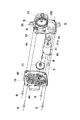
- FIG. 1 is an external perspective view showing an embodiment of an intake control device according to the present invention. It is a perspective view which shows a part (assembly) of the intake control device which concerns on this invention.
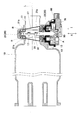
- FIG. 2 is a cross-sectional view schematically showing the intake control device shown in FIG. 1.
- FIG. 3 is an exploded perspective view of a part (assembly) of the intake air control device shown in FIG. 2.
- FIG. 3 is an exploded perspective view of a part (assembly) of the intake air control device shown in FIG. 2.
- FIG. 3 is a cross-sectional view of the intake air control device shown in FIG. It is sectional drawing which shows other embodiment of the intake control apparatus which concerns on this invention.
- This intake control device includes a passage member 10 that forms a part of an intake system of an internal combustion engine, and an assembly A that is detachably assembled to the passage member 10.
- the assembly A includes a throttle body 20, a throttle valve 30 provided in the throttle body 20, an electric motor 40 that generates a driving force for opening and closing the throttle valve 30, and the electric motor 40.
- a power transmission mechanism 50 that transmits driving force to the throttle valve 30; a heat transfer member 60 that transmits heat generated by the electric motor 40; a cover member 70 that is assembled to the throttle body 20; and a position that detects the opening position of the throttle valve 30.
- a sensor 90 and a connector 90 for electrically connecting the electric motor 40 are provided.
- the passage member 10 is formed of a resin material, and as shown in FIGS. 1 and 3, the intake passage 11 that guides intake air toward the intake port of the internal combustion engine, a direction crossing the intake passage 11 (relative to the extending direction L). And the mounting portion 13 formed around the insertion port 12.
- the insertion port 12 can be inserted into the assembly A (the throttle body 20, the electric motor 40, and the heat transfer member 60).
- the housing chamber 14 that surrounds and accommodates the assembly A inserted from the insertion port 12 is joined to the throttle body 20 of the assembly A (the wall surfaces 21b that define both ends of the throttle bore 21a formed in the cylindrical portion 21).
- the passage member 10 is formed of a resin material having a lower thermal conductivity than a metal material or the like, the heat accumulated inside is radiated to the outside air through the wall portion of the passage member 10. Can be suppressed.
- a female screw member 13 a that defines a female screw for fastening a part of the throttle body 20 (a flange portion 22 described later) with a screw B is embedded in the attachment portion 13.
- the storage chamber 14 is formed so as to follow the outline of the inserted assembly A (the throttle body 20 and the electric motor 40) with a predetermined minute gap. In this way, by providing a layer of air with a small gap between the inner wall surface of the storage chamber 14 and the assembly A, the assembly A (the cylindrical portion 21 and the electric motor 40) is transferred to the passage member 10 (outer wall). Heat transfer (heat dissipation) can be suppressed.
- the two joining surfaces 17 are not parallel to each other, and approach each other toward the insertion direction I (the back side of the storage chamber 14) in which the assembly A is inserted into the storage chamber 14 of the passage member 10. It is formed (to taper).
- the throttle body 20 positions and holds the cylindrical portion 21 defining the throttle bore 21a, the cylindrical portion 21 and the electric motor 40 on one side, and the power transmission mechanism 50 on the other side. And the flange portion 22 and the like formed so that the cover member 70 is attached.
- the cylindrical portion 21 is made of a metal material (for example, aluminum material) having a high thermal conductivity, and is fixed to the passage member 10 as shown in FIGS. 2, 3, and 6. 11, a throttle bore 21 a communicating with the throttle 11, two wall surfaces 21 b defining both ends of the throttle bore 21 a, a bearing hole 21 c for rotatably supporting a throttle shaft 31 for opening and closing the throttle valve 30 in the throttle bore 21 a, a flange A fitting recess 21d that fits into the fitting portion 22 (the fitting projection 22b), an outer wall 21e that defines the throttle bore 21a, a cylindrical portion 21f formed on the tip end side of the bearing hole 21c, and the like are provided. As shown in FIG.
- the two wall surfaces 21 b are formed in a wedge shape that tapers in the insertion direction I (the back side of the storage chamber 14) so as to face the two joint surfaces 17 of the passage member 10. ing.
- the flange part 22 is fastened and fixed so that the cylindrical part 21 is inserted and pressed down, whereby the end face 21b of the throttle bore 21a.
- the end surface (joint surface 17) that defines the intake passage 11 of the passage member 10 can be brought into close contact with each other via a seal member R made of a rubber material or the like.
- the flange portion 22 is formed of a resin material having low thermal conductivity, and in two places in the vertical direction, a through hole 22a through which the screw B is passed, and on one side (side facing the storage chamber 14), a cylindrical portion 21 (fitting recess 21d) is fitted with a fitting convex portion 22b, a concave portion 22c for fitting and fixing a bearing G that rotatably supports the throttle shaft 31, and a cylindrical portion 21 is fastened and fixed with a screw B.
- Female screw portion 22d for carrying out, on the other side (side facing the outer side opposite to the accommodation chamber 14), a concave portion 22e for arranging and holding a part of the power transmission mechanism 50, and a coupling portion 22f for assembling the cover member 70
- a fixing portion 22g for fixing the flange 42 of the electric motor 40, a through hole 22h formed so as to pass the electric motor 40 from the other side and positioned on the one side, a support shaft 22i, and the like are provided.
- the flange portion 22 is formed so as to close the insertion port 12 of the passage member 10 by being bonded and fixed to the attachment portion 13 of the passage member 10.
- the assembly A is firmly fixed to the passage member 10 via the flange portion 22, and a part thereof (the cylindrical portion 21, the electric motor 40, the heat transfer member 60) is formed of the resin material. 10 and the flange portion 22 formed of the resin material, the heat generated by the electric motor 40 can be more reliably suppressed from being radiated to the outside.
- the throttle body 20 (cylindrical portion 21 and flange portion 22) configured as described above, the electric motor 40 is not accommodated in the throttle body 20, but is accommodated in the accommodating chamber 14 of the passage member 10. Therefore, the throttle body 20 can be formed small, and as a result, the assembly A including the throttle body 20, the electric motor 40, the heat transfer member 60, and the like can be reduced in size, weight, cost, and the like. .
- the throttle valve 30 is fastened and fixed to the throttle shaft 31, and is supported in the throttle bore 21a so that the passage can be freely opened and closed.
- One end side of the throttle shaft 31 is rotatably supported by the bearing hole 21c of the cylindrical portion 21, a middle region thereof is rotatably supported by the bearing G provided in the flange portion 22, and the other end side is powered.
- a gear 52 forming a part of the transmission mechanism 50 is fixed so as to rotate integrally.
- the electric motor 40 protrudes from a substantially cylindrical motor housing 41 containing a rotor, a coil, a magnet, and the like, a flange 42 fixed to an end surface of the motor housing 41, and the flange 42.
- a drive gear 43 and the like fixed to the rotation shaft are provided.
- the electric motor 40 is configured such that the motor housing 41 is passed through the through hole 22h from the other side of the flange portion 22 and fastened and fixed to the fixing portion 22g with screws B.
- the motor housing 41 is positioned with a predetermined gap immediately below the cylindrical portion 21 on one side of the flange portion 22. Yes.
- a spacer 44 (see FIGS. 4 and 5) is fitted as necessary.
- the spacer 44 may be a wave washer, an O-ring, or the like.
- the power transmission mechanism 50 is disposed on the other side of the flange portion 22 (of the throttle body 20), and integrally includes a large gear 51a and a small gear 51b that mesh with the drive gear 43.
- the driven gear 52 which is meshed with the intermediate gear 51 and the small gear 51b, and fixed to the throttle shaft 31, and the throttle valve 30 at a rest position (for example, an idle opening degree that opens the passage by a predetermined minute angle, Alternatively, a return spring 53 that rotationally biases the throttle shaft 31 so as to return to a position of a default opening that is opened only by a startable angle), a holder 54 that holds the return spring 53, and the like are provided.
- the intermediate gear 51 is fitted to a support shaft 22 i protruding from the flange portion 22 and is rotatably supported.
- the return spring 53 is disposed in the recess 22e of the flange portion 22 while being held inside the two holders 54, one end of which is hooked on a part of the holder 54 held by the flange portion 22, and the others.
- the end portion is hooked on a part of the holder 54 held by the driven gear 52 and is configured to exert a rotational biasing force on the throttle shaft 31 so as to return the throttle valve 30 to the rest position.
- the heat transfer member 60 includes a motor housing 41 of the electric motor 40 (an outer peripheral surface of the rear end side region) and a cylindrical portion 21 (the outer wall 21e defining the throttle bore 21a thereof). It is provided so as to be interposed therebetween.
- a deformable material for example, silicone gel
- the cylindrical portion 21 and the electric motor 40 are fixed to the flange portion 22, they are interposed between the two. To be filled.
- the heat transfer member 60 is made of a deformable material, there is no gap between the electric motor 40 (the motor housing 41) and the outer wall 21e of the cylindrical portion 21 without any gaps freely.
- the heat member 60 can be filled, and the heat transfer efficiency from the motor housing 41 to the outer wall 21e (of the cylindrical portion 21) defining the throttle bore 21a can be increased. Thereby, it is possible to reliably prevent moisture icing in the area of the throttle bore 21a where the throttle valve 30 is disposed.
- the cover member 70 is made of a resin material having a low thermal conductivity, and holds the position sensor 80 and the connector 90 and covers the power transmission mechanism 50 as shown in FIGS. It is joined to a coupling part 22 f formed on the other side of the part 22 and attached by a screw B. As described above, since the resin cover member 70 is arranged outside the flange portion 22, the heat generated from the electric motor 40 is radiated to the outside not only by the flange portion 22 but also by the cover member 70. Can be suppressed. In addition, since the position sensor 80 and the connector 90 are disposed on the cover member 70, no complicated wiring or the like is required, and only the cover member 70 is attached to the flange portion 22 to the electric motor 40 and the position sensor 80. The energization circuit and the signal detection circuit can be configured.
- the position sensor 80 has a detection portion disposed on the inner wall side of the cover member 70, a detected portion is disposed on the throttle shaft 31, and the throttle shaft 31, that is, the throttle shaft 31 based on an electric signal obtained by the interaction between the two. It is formed so as to detect the opening position of the valve 30.
- the connector 90 is formed so as to protrude from the cover member 70, and includes a terminal that electrically connects the electric motor 40, a terminal that electrically connects the position sensor 80, and the like. ing.
- the power transmission mechanism 50 is assembled to the other end side of the flange portion 22 and the throttle shaft 31 so as to be positioned on the other side of the flange portion 22.
- the cylindrical portion 21 on which the throttle valve 30 is disposed is assembled to the flange portion 22 so as to be positioned on one end side of the flange portion 22.
- the electric motor 40 is assembled to the flange portion 22 so as to be positioned on one side of the flange portion 22 through the through hole 22h.
- the cover member 70 is brought closer to the flange portion 22 from the other side of the flange portion 22 so as to cover the power transmission mechanism 50.
- the heat transfer member 60 is provided so as to be interposed between the cylindrical portion 21 positioned on one side of the flange portion 22 and the motor housing 41 of the electric motor 40.
- the sealing member R is fitted into the two wall surfaces 21 b of the cylindrical portion 21.
- the assembly A is moved closer to the passage member 10 from the direction X crossing the intake passage 11 so that the cylindrical portion 21, the electric motor 40, and the heat transfer member 60 are accommodated in the accommodation chamber 14.
- the two wall surfaces 21b of the cylindrical portion 21 are joined so as to be in close contact with the two joining surfaces 17 of the passage member 10 via the seal member R, and the seal member R is compressed so that the flange portion 22 is compressed. Is fastened and fixed by the screw B while being joined to the attachment portion 13.
- the throttle bore 21a of the tubular portion 21 communicates with the intake passage 11 of the passage member 10, and the tubular portion 21, the electric motor 40, and the heat transfer member 60 are formed of a resin material. Therefore, the heat generated by the electric motor 40 is controlled around the throttle valve 30 through the heat transfer member 60 while suppressing heat radiation from the wall surface of the passage member 10 to the outside. A structure having a heat transfer path that can be efficiently transmitted to the metallic cylindrical portion 21 is obtained.
- the throttle valve 30 When the electric motor 40 is not energized, the throttle valve 30 is positioned at the rest position by the return spring 53.
- the electric motor 40 when the electric motor 40 is energized, a rotational driving force is obtained, and the throttle shaft 31 and the throttle valve 30 are rotationally driven via the driving gear 41, the intermediate gear 51 and the driven gear 52. Then, by appropriately controlling the direction of energization, the throttle valve 30 is appropriately rotated to the opening side or the closing side, and the opening degree is adjusted.
- the electric motor 40 when the electric motor 40 is de-energized, the throttle valve 30 is returned to the initial rest position by the biasing force of the return spring 53.
- the heat generated from the electric motor 40 is prevented from radiating to the outside from the wall surface of the passage member 10 or the like, and the cylindrical portion is interposed in the accommodation chamber 14 via the heat transfer member 60. Therefore, the heat generated by the electric motor 40 can be used effectively (efficiently) to prevent icing (icing) from occurring around the throttle valve 30 especially after the engine is stopped.
- the arrangement in the intake system can be easily performed while the structure is simplified, the number of parts is reduced, the apparatus is downsized, the cost is reduced, and the weight is reduced.
- icing icing
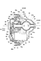
- FIG. 7 shows another embodiment of the intake control device according to the present invention.
- This embodiment is the same as the above-described embodiment except that the heat transfer member is integrally formed of the same metal material as the cylindrical portion 21 '. Accordingly, the same components are denoted by the same reference numerals and description thereof is omitted. That is, the cylindrical portion 21 ′ is integrally provided with a heat transfer piece 21 g as a heat transfer member that transfers heat of the electric motor 40 fixed to the flange portion 22.
- the heat transfer piece 21g defines a curved contact surface 21g ′ that is curved so as to be in close contact with the motor housing 41 of the electric motor 40.
- the number of parts can be reduced and the number of assembling steps can be reduced, and the heat generated from the electric motor 40 can be reduced by the wall surface region of the cylindrical portion 21 ′. It can be transmitted efficiently. Further, a more efficient heat transfer action can be obtained by joining the heat transfer piece to the motor end portion side where heat is easily generated.
- the arrangement in the intake system is easy while achieving the simplification of the structure, the reduction of the number of parts, the miniaturization of the device, the reduction in cost, the weight reduction, and the like, as in the above-described embodiment.
- the heat generated by the drive source (electric motor 40) of the throttle valve 30 can be effectively (efficiently) used to reliably prevent icing (icing) and the like around the throttle valve 30.
- the throttle body 20 in which the cylindrical portions 21 and 21 ′ are formed of a metal material and the flange portion 22 is formed of a resin material is shown as a throttle body.
- the cylindrical part and the flange part may be integrally formed of a metal material.
- the heat transmitted to the flange portion can be prevented from being radiated to the outside by the cover member 70.
- icing icing
- the like around the throttle valve 30 can be reliably prevented.
- the heat-transfer piece 21g was provided in close contact with the motor housing 41 was shown, it is not limited to this, The motor housing 41 is provided with a slight gap. Also good.
- the intake control device is easy to arrange in the intake system while achieving simplification of the structure, reduction in the number of parts, downsizing of the device, cost reduction, weight reduction, etc.
- the internal combustion engine mounted on automobiles, motorcycles, etc. used in cold regions, because it can effectively prevent the icing (icing) around the throttle valve by effectively using the heat generated by the throttle valve drive source. And is also useful in vehicles equipped with other internal combustion engines.
Landscapes
- Engineering & Computer Science (AREA)
- Chemical & Material Sciences (AREA)
- Combustion & Propulsion (AREA)
- Mechanical Engineering (AREA)
- General Engineering & Computer Science (AREA)
- Control Of Throttle Valves Provided In The Intake System Or In The Exhaust System (AREA)
Abstract
本発明の吸気制御装置は、通路部材(10)、スロットルボディ(20)、スロットルバルブ(30)、電動モータ(40)、動力伝達機構(50)を備え、スロットルボディ(20)は、スロットルボアを画定する金属製の筒状部(21)、一方側において筒状部及び電動モータをかつ他方側において動力伝達機構をそれぞれ位置付けて保持するフランジ部(22)を有し、伝熱部材(60)が電動モータと筒状部との間に介在するように設けられ、通路部材(10)が、樹脂製で、吸気通路を横切る方向から,スロットルボディの筒状部,伝熱部材,及び電動モータを含むアセンブリ(A)を挿入する挿入口、挿入口から挿入されたアセンブリを囲繞して収容する収容室を有する。これによれば、電動モータの発熱を有効に利用してスロットルバルブ周りの氷結を確実に防止できる。
Description
本発明は、内燃エンジンの吸気系に配置される吸気制御装置に関し、特に、吸気通路を開閉するスロットルバルブを電動モータにより開閉駆動する吸気制御装置に関する。
自動車等に搭載される内燃エンジンの吸気制御装置としては、吸気管に対して吸気通路の伸長方向から着脱自在に固定されると共に吸気通路に連通するスロットルボアを画定するように樹脂材料により形成されたスロットルボディ、スロットルボアを開閉するべくスロットルボディに組み込まれたスロットルバルブ、スロットルボディにより画定される収容空間内に配置された電動モータ、電動モータの回転駆動力をスロットルバルブ(のシャフト)に伝達する動力伝達機構等を備えた構成において、吸気通路を画定する通路外壁と電動モータとの間に金属ブロックを配置し、金属ブロックを介して電動モータの熱を吸気通路の壁面(スロットルバルブの周り)に伝達することにより、水分等の氷結(アイシング)等を防止するようにしたものが知られている(例えば、特許文献1参照)。
この装置においては、スロットルボディそのものが、吸気系の輪郭の一部をなすように露出した状態で吸気管に継ぎ足すように形成されているため、吸気系(吸気管、吸気コレクタ、吸気導入ダクト等)のレイアウトに制約がある場合に、その配置は容易ではなく、又、スロットルボディそのものが電動モータを収容するように形成されているため全体的に外輪郭が大きくなり、さらに、吸気通路を画定する円筒部を含めてスロットルボディ全体が樹脂材料により形成されているため、電動モータから発せられた熱は、金属ブロックまでは伝わるとしても、吸気通路を画定する樹脂製の円筒部には伝わり難く、金属ブロックから放熱してしまい効率が悪い。
この装置においては、スロットルボディそのものが、吸気系の輪郭の一部をなすように露出した状態で吸気管に継ぎ足すように形成されているため、吸気系(吸気管、吸気コレクタ、吸気導入ダクト等)のレイアウトに制約がある場合に、その配置は容易ではなく、又、スロットルボディそのものが電動モータを収容するように形成されているため全体的に外輪郭が大きくなり、さらに、吸気通路を画定する円筒部を含めてスロットルボディ全体が樹脂材料により形成されているため、電動モータから発せられた熱は、金属ブロックまでは伝わるとしても、吸気通路を画定する樹脂製の円筒部には伝わり難く、金属ブロックから放熱してしまい効率が悪い。
また、他の吸気制御装置としては、吸気管に対して吸気通路を横切るように差し込まれて固定されると共に吸気通路と連通するスロットルボアを画定するスロットルボディ、スロットルボアを開閉するべくスロットルボディに組み込まれたスロットルバルブ等を備えた構成において、水分等の凝縮液がスロットルバルブの周りに流れ込むのを規制する規制壁を、スロットルバルブよりも上流側及び下流側に設けて、氷結(アイシング)等を防止するようにしたものが知られている(例えば、特許文献2を参照)。
この装置においては、スロットルボディが吸気管に対して吸気通路を横切るように差し込まれて固定されるものであるため、前述のような継ぎ足しによるレイアウト上の制約、大型化等の問題は解消されるものの、鉛直方向の上側と下側に配置された方向性に依存する規制壁により単に凝縮液の流れを規制するだけであって、スロットルバルブの近傍に発熱源を配置するものではないため、自動車等の状態すなわち吸気管(スロットルボディ)の姿勢によっては、氷結等を完全に防止できない虞がある。
この装置においては、スロットルボディが吸気管に対して吸気通路を横切るように差し込まれて固定されるものであるため、前述のような継ぎ足しによるレイアウト上の制約、大型化等の問題は解消されるものの、鉛直方向の上側と下側に配置された方向性に依存する規制壁により単に凝縮液の流れを規制するだけであって、スロットルバルブの近傍に発熱源を配置するものではないため、自動車等の状態すなわち吸気管(スロットルボディ)の姿勢によっては、氷結等を完全に防止できない虞がある。
本発明は、上記の事情に鑑みて成されたものであり、その目的とするところは、構造の簡素化、部品点数の削減、装置の小型化、低コスト化、軽量化等を図りつつ、吸気系における配置が容易であり、スロットルバルブの駆動源による発熱を有効に(効率良く)利用して、スロットルバルブの周りにおける氷結(アイシング)等を確実に防止することができる吸気制御装置を提供することにある。
本発明に係る吸気制御装置は、樹脂材料により形成されて吸気通路を画定する通路部材と、通路部材に固定されて吸気通路と連通するスロットルボアを画定するスロットルボディと、スロットルボアを開閉するべくスロットルボディに設けられたスロットルバルブと、スロットルバルブを開閉駆動するための駆動力を生じる電動モータと、電動モータの駆動力をスロットルバルブに伝達する動力伝達機構と、電動モータから発せられる熱を伝える伝熱部材とを備えた吸気制御装置であって、上記スロットルボディは、スロットルボアを画定するべく金属材料により形成された筒状部と、一方側において筒状部及び電動モータを位置付けて保持しかつ他方側において動力伝達機構を位置付けて保持するように形成されたフランジ部とを有し、上記伝熱部材は、電動モータと筒状部との間に介在するように設けられ、上記通路部材は、吸気通路を横切る方向から,スロットルボディの筒状部,伝熱部材,及び電動モータを含むアセンブリを挿入する挿入口と、挿入口から挿入されたアセンブリを囲繞して収容する収容室とを有する、構成となっている。
この構成によれば、スロットルボディの(スロットルバルブが設けられた)筒状部、伝熱部材、及び電動モータを含むアセンブリが、通路部材の挿入口から収容室内に挿入されて固定されると、筒状部のスロットルボアが通路部材の吸気通路と連通し、筒状部、伝熱部材、及び電動モータが、樹脂材料により形成された通路部材により囲繞されるため、電動モータにより発せられた熱は、通路部材の壁面等から外部への放熱が抑制されつつ、伝熱部材を介して金属製の筒状部に効率良く伝わり、スロットルバルブの周りにおける氷結(アイシング)等を防止することができる。
また、電動モータは、スロットルボディに収容されるのではなく、通路部材の収容室に収容されるため、スロットルボディを小さく形成することができ、スロットルボディ、電動モータ、伝熱部材等を含むアセンブリの小型化、軽量化、低コスト化等を達成することができる。
この構成によれば、スロットルボディの(スロットルバルブが設けられた)筒状部、伝熱部材、及び電動モータを含むアセンブリが、通路部材の挿入口から収容室内に挿入されて固定されると、筒状部のスロットルボアが通路部材の吸気通路と連通し、筒状部、伝熱部材、及び電動モータが、樹脂材料により形成された通路部材により囲繞されるため、電動モータにより発せられた熱は、通路部材の壁面等から外部への放熱が抑制されつつ、伝熱部材を介して金属製の筒状部に効率良く伝わり、スロットルバルブの周りにおける氷結(アイシング)等を防止することができる。
また、電動モータは、スロットルボディに収容されるのではなく、通路部材の収容室に収容されるため、スロットルボディを小さく形成することができ、スロットルボディ、電動モータ、伝熱部材等を含むアセンブリの小型化、軽量化、低コスト化等を達成することができる。
上記構成において、フランジ部は、筒状部とは別体に樹脂材料により形成され、筒状部は、フランジ部に固定されている、構成を採用することができる。
この構成によれば、スロットルボディのフランジ部は、樹脂材料により形成されるため、スロットルボディをより軽量化することができると共に、電動モータにより発せられた熱が、スロットルボディのフランジ部に伝わるのを又フランジ部を経て外部に放熱されるのを抑制することができ、伝熱部材を介して金属製の筒状部に効率良く伝えることができる。
この構成によれば、スロットルボディのフランジ部は、樹脂材料により形成されるため、スロットルボディをより軽量化することができると共に、電動モータにより発せられた熱が、スロットルボディのフランジ部に伝わるのを又フランジ部を経て外部に放熱されるのを抑制することができ、伝熱部材を介して金属製の筒状部に効率良く伝えることができる。
上記構成において、フランジ部は、通路部材の挿入口を閉塞するように通路部材に接合して固定されている、構成を採用することができる。
この構成によれば、スロットルボディ、伝熱部材、及び電動モータを含むアセンブリが、フランジ部を介して通路部材に堅固に固定されると共に、スロットルボディの筒状部、伝熱部材、及び電動モータが、樹脂材料により形成された通路部材及び樹脂材料により形成されたフランジ部により完全に囲繞されるため、電動モータにより発せられた熱は、外部への放熱がより確実に抑制されつつ、伝熱部材を介して金属製の筒状部に一層効率良く伝えられ得る。
この構成によれば、スロットルボディ、伝熱部材、及び電動モータを含むアセンブリが、フランジ部を介して通路部材に堅固に固定されると共に、スロットルボディの筒状部、伝熱部材、及び電動モータが、樹脂材料により形成された通路部材及び樹脂材料により形成されたフランジ部により完全に囲繞されるため、電動モータにより発せられた熱は、外部への放熱がより確実に抑制されつつ、伝熱部材を介して金属製の筒状部に一層効率良く伝えられ得る。
上記構成において、伝熱部材は、変形自在な材料からなる、構成を採用することができる。
この構成によれば、伝熱部材として変形自在な材料(例えば、シリコーンゲル等)を用いることにより、電動モータ(のモータハウジング)と筒状部との間に、相互の輪郭に合わせて自在に隙間なく充填することができ、伝熱効率を高めることができる。
この構成によれば、伝熱部材として変形自在な材料(例えば、シリコーンゲル等)を用いることにより、電動モータ(のモータハウジング)と筒状部との間に、相互の輪郭に合わせて自在に隙間なく充填することができ、伝熱効率を高めることができる。
上記構成において、伝熱部材は、スロットルボディの筒状部と同一の金属材料により一体的に形成されている、構成を採用することができる。
この構成によれば、部品点数を削減することができると共に、電動モータから発せられた熱を筒状部の壁面領域により効率良く伝達することができる。
この構成によれば、部品点数を削減することができると共に、電動モータから発せられた熱を筒状部の壁面領域により効率良く伝達することができる。
上記構成において、スロットルボディのフランジ部には、動力伝達機構を覆うにように樹脂材料により形成されたカバー部材が組み付けられている、構成を採用することができる。
この構成によれば、フランジ部の外側に樹脂製のカバー部材が配置されるため、このカバー部材によっても電動モータから発せられた熱が外部に放熱されるのを抑制することができ、特に、フランジ部が筒状部と一体的に金属材料により形成された場合には、有効な放熱抑制効果が得られる。
この構成によれば、フランジ部の外側に樹脂製のカバー部材が配置されるため、このカバー部材によっても電動モータから発せられた熱が外部に放熱されるのを抑制することができ、特に、フランジ部が筒状部と一体的に金属材料により形成された場合には、有効な放熱抑制効果が得られる。
上記構成において、カバー部材には、スロットルバルブの開度位置を検出する位置センサ及び電気的接続を行うコネクタが配置されている、構成を採用することができる。
この構成によれば、フランジ部にカバー部材を取り付けるだけで、電動モータ及び位置センサの作動を可能とする構成を採ることができる。
この構成によれば、フランジ部にカバー部材を取り付けるだけで、電動モータ及び位置センサの作動を可能とする構成を採ることができる。
上記構成において、スロットルボディの筒状部は、スロットルボアの両端を画定する壁面が通路部材への挿入方向に向けて先細りするくさび状に形成されている、構成を採用することができる。
この構成によれば、スロットルボディを通路部材に組み付ける際に、筒状部を挿入して押さえ込むことで、スロットルボアの両端面と通路部材の吸気通路を画定する端面同士を、シール部材等を介して確実に密接させることができる。
この構成によれば、スロットルボディを通路部材に組み付ける際に、筒状部を挿入して押さえ込むことで、スロットルボアの両端面と通路部材の吸気通路を画定する端面同士を、シール部材等を介して確実に密接させることができる。
上記構成をなす吸気制御装置によれば、構造の簡素化、部品点数の削減、装置の小型化、低コスト化、軽量化等を達成しつつ、吸気系における配置が容易であり、スロットルバルブの駆動源による発熱を有効に(効率良く)利用して、スロットルバルブの周りにおける氷結(アイシング)等を確実に防止することができる。
以下、本発明の実施の形態について、添付図面を参照しつつ説明する。
この吸気制御装置は、内燃エンジンの吸気系の一部をなす通路部材10、通路部材10に対して着脱自在に組み付けられるアセンブリAを備えている。
アセンブリAは、図2ないし図6に示すように、スロットルボディ20、スロットルボディ20に設けられたスロットルバルブ30、スロットルバルブ30を開閉駆動するための駆動力を生じる電動モータ40、電動モータ40の駆動力をスロットルバルブ30に伝達する動力伝達機構50、電動モータ40から発せられる熱を伝える伝熱部材60、スロットルボディ20に組み付けられたカバー部材70、スロットルバルブ30の開度位置を検出する位置センサ80、電動モータ40の電気的接続を行うコネクタ90等を備えている。
この吸気制御装置は、内燃エンジンの吸気系の一部をなす通路部材10、通路部材10に対して着脱自在に組み付けられるアセンブリAを備えている。
アセンブリAは、図2ないし図6に示すように、スロットルボディ20、スロットルボディ20に設けられたスロットルバルブ30、スロットルバルブ30を開閉駆動するための駆動力を生じる電動モータ40、電動モータ40の駆動力をスロットルバルブ30に伝達する動力伝達機構50、電動モータ40から発せられる熱を伝える伝熱部材60、スロットルボディ20に組み付けられたカバー部材70、スロットルバルブ30の開度位置を検出する位置センサ80、電動モータ40の電気的接続を行うコネクタ90等を備えている。
通路部材10は、樹脂材料により形成されており、図1及び図3に示すように、吸気を内燃エンジンの吸気ポートに向けて導く吸気通路11、吸気通路11を横切る方向(伸長方向Lに対して略垂直な方向X)に向けて開口しアセンブリA(のスロットルボディ20、電動モータ40、及び伝熱部材60)を挿入し得る挿入口12、挿入口12の周りに形成された取り付け部13、挿入口12から挿入されたアセンブリAを囲繞して収容する収容室14、アセンブリAのスロットルボディ20(の筒状部21に形成されたスロットルボア21aの両端を画定する壁面21b)を接合するべく吸気通路11の伸長方向Lにおいて対向する二つの接合面17、吸気系の一部をなす上流側の吸気ダクトを接合するパイプ部18等を備えている。
このように、通路部材10は、金属材料等に比べて熱伝導率が低い樹脂材料により形成されているため、内部にこもった熱が通路部材10の壁部を通して外部の空気中に放熱されるのを抑制することができる。
このように、通路部材10は、金属材料等に比べて熱伝導率が低い樹脂材料により形成されているため、内部にこもった熱が通路部材10の壁部を通して外部の空気中に放熱されるのを抑制することができる。
取り付け部13には、図6に示すように、スロットルボディ20の一部(後述するフランジ部22)をネジBにより締結するための雌ネジを画定する雌ネジ部材13aが埋設されている。また、別の取付手法としては、雌ネジ部材13aを用いず、タッピングネジ等を用いて、取り付け部13に直接固定することもできる。
収容室14は、挿入されたアセンブリA(のスロットルボディ20及び電動モータ40)の輪郭に所定の微小隙間をおいて沿うように形成されている。このように、収容室14の内壁面とアセンブリAとの間に微小隙間をあけて空気の層を設けることで、アセンブリA(筒状部21及び電動モータ40)から通路部材10(外壁)への伝熱(放熱)を抑制することができる。
収容室14は、挿入されたアセンブリA(のスロットルボディ20及び電動モータ40)の輪郭に所定の微小隙間をおいて沿うように形成されている。このように、収容室14の内壁面とアセンブリAとの間に微小隙間をあけて空気の層を設けることで、アセンブリA(筒状部21及び電動モータ40)から通路部材10(外壁)への伝熱(放熱)を抑制することができる。
二つの接合面17は、図3に示すように、互いに平行ではなく、アセンブリAを通路部材10の収容室14に挿入する挿入方向I(収容室14の奥側)に向けて互いに近づくように(先細りするように)形成されている。
スロットルボディ20は、図2ないし図6に示すように、スロットルボア21aを画定する筒状部21、一方側において筒状部21及び電動モータ40を位置付けて保持しかつ他方側において動力伝達機構50を位置付けて保持すると共にカバー部材70が取り付けられるように形成されたフランジ部22等により構成されている。
筒状部21は、熱伝導率の高い金属材料(例えば、アルミニウム材料)により形成されており、図2、図3、図6に示すように、通路部材10に固定された状態で、吸気通路11と連通するスロットルボア21a、スロットルボア21aの両端を画定する二つの壁面21b、スロットルボア21a内においてスロットルバルブ30を開閉自在に支持するスロットルシャフト31を回動自在に支持する軸受孔21c、フランジ部22(の嵌合凸部22b)に嵌合する嵌合凹部21d、スロットルボア21aを画定する外壁21e、軸受孔21cの先端側に形成された円筒部21f等を備えている。
二つの壁面21bは、図3に示すように、通路部材10の二つの接合面17とそれぞれ対向するように、挿入方向I(収容室14の奥側)に向けて先細りするくさび状に形成されている。
これによれば、スロットルボディ20(筒状部21)を通路部材10に組み付ける際に、筒状部21を挿入して押さえ込むようにフランジ部22を締結固定することで、スロットルボア21aの端面21bと通路部材10の吸気通路11を画定する端面(接合面17)とを、ゴム材料等からなるシール部材R等を介して確実に密接させることができる。
二つの壁面21bは、図3に示すように、通路部材10の二つの接合面17とそれぞれ対向するように、挿入方向I(収容室14の奥側)に向けて先細りするくさび状に形成されている。
これによれば、スロットルボディ20(筒状部21)を通路部材10に組み付ける際に、筒状部21を挿入して押さえ込むようにフランジ部22を締結固定することで、スロットルボア21aの端面21bと通路部材10の吸気通路11を画定する端面(接合面17)とを、ゴム材料等からなるシール部材R等を介して確実に密接させることができる。
フランジ部22は、熱伝導率の低い樹脂材材料により形成されており、上下方向の二箇所において、ネジBを通す貫通孔22a、一方側(収容室14に面する側)において、筒状部21(の嵌合凹部21d)を嵌合する嵌合凸部22b、スロットルシャフト31を回動自在に支持する軸受Gを嵌合して固定する凹部22c、筒状部21をネジBにより締結固定するための雌ネジ部22d、他方側(収容室14と反対側の外側に面する側)において、動力伝達機構50の一部を配置して保持する凹部22e、カバー部材70を組み付ける結合部22f、電動モータ40のフランジ42を固定する固定部22g、電動モータ40を他方側から通して一方側に位置付けるように形成された貫通孔22h、支軸22i等を備えている。
また、フランジ部22は、通路部材10の取り付け部13に接合して固定されることで、通路部材10の挿入口12を閉塞するように形成されている。
これにより、アセンブリAが、フランジ部22を介して通路部材10に堅固に固定されると共にその一部(筒状部21、電動モータ40、伝熱部材60)が樹脂材料により形成された通路部材10及び樹脂材料により形成されたフランジ部22により完全に囲繞されるため、電動モータ40により発せられた熱が外部へ放熱されるのをより確実に抑制することができる。
上記のような構成をなすスロットルボディ20(筒状部21及びフランジ部22)によれば、電動モータ40はスロットルボディ20に収容されるのではなく、通路部材10の収容室14に収容されるため、スロットルボディ20を小さく形成することができ、その結果、スロットルボディ20、電動モータ40、伝熱部材60等を含むアセンブリAの小型化、軽量化、低コスト化等を達成することができる。
これにより、アセンブリAが、フランジ部22を介して通路部材10に堅固に固定されると共にその一部(筒状部21、電動モータ40、伝熱部材60)が樹脂材料により形成された通路部材10及び樹脂材料により形成されたフランジ部22により完全に囲繞されるため、電動モータ40により発せられた熱が外部へ放熱されるのをより確実に抑制することができる。
上記のような構成をなすスロットルボディ20(筒状部21及びフランジ部22)によれば、電動モータ40はスロットルボディ20に収容されるのではなく、通路部材10の収容室14に収容されるため、スロットルボディ20を小さく形成することができ、その結果、スロットルボディ20、電動モータ40、伝熱部材60等を含むアセンブリAの小型化、軽量化、低コスト化等を達成することができる。
スロットルバルブ30は、図6に示すように、スロットルシャフト31に締結固定されて、スロットルボア21a内において通路を開閉自在に支持されている。
スロットルシャフト31は、その一端側が筒状部21の軸受孔21cにより回動自在に支持され、その途中領域がフランジ部22に設けられた軸受Gにより回動自在に支持され、その他端側において動力伝達機構50の一部をなす歯車52が一体的に回転するように固定されている。
スロットルシャフト31は、その一端側が筒状部21の軸受孔21cにより回動自在に支持され、その途中領域がフランジ部22に設けられた軸受Gにより回動自在に支持され、その他端側において動力伝達機構50の一部をなす歯車52が一体的に回転するように固定されている。
電動モータ40は、図4ないし図6に示すように、ロータ、コイル、磁石等を内蔵する略円筒状のモータハウジング41、モータハウジンング41の端面に固定されたフランジ42、フランジ42から突出する回転軸に固定された駆動歯車43等を備えている。
そして、電動モータ40は、モータハウジング41がフランジ部22の他方側から貫通孔22hに通されて固定部22gにネジBにより締結固定されるようになっている。
そして、電動モータ40がフランジ部22に固定(保持)された状態で、モータハウジング41がフランジ部22の一方側において筒状部21の直下に、所定の隙間をおいて位置付けられるようになっている。
尚、電動モータ40が、通路部材10の収容室14に挿入される際には、必要に応じてスペーサ44(図4及び図5参照)が嵌め込まれるようになっている。スペーサ44としては、ウェーブワッシャ、Oリング等でもよい。
そして、電動モータ40は、モータハウジング41がフランジ部22の他方側から貫通孔22hに通されて固定部22gにネジBにより締結固定されるようになっている。
そして、電動モータ40がフランジ部22に固定(保持)された状態で、モータハウジング41がフランジ部22の一方側において筒状部21の直下に、所定の隙間をおいて位置付けられるようになっている。
尚、電動モータ40が、通路部材10の収容室14に挿入される際には、必要に応じてスペーサ44(図4及び図5参照)が嵌め込まれるようになっている。スペーサ44としては、ウェーブワッシャ、Oリング等でもよい。
動力伝達機構50は、図4ないし図6に示すように、(スロットルボディ20の)フランジ部22の他方側に配置されており、駆動歯車43に噛合する大歯車51a及び小歯車51bを一体的に有する二段式の中間歯車51、小歯車51bに噛合すると共にスロットルシャフト31に固定された従動歯車52、スロットルバルブ30を休止位置(例えば、通路を所定の微小角度だけ開放するアイドル開度、又は、始動可能な角度だけ開放するデフォルト開度の位置)に戻すようにスロットルシャフト31を回転付勢する戻しバネ53、戻しバネ53を保持するホルダ54等を備えている。
中間歯車51は、フランジ部22から突出する支軸22iに嵌め込まれて回動自在に支持されている。
戻しバネ53は、2つのホルダ54の内側に保持された状態で、フランジ部22の凹部22eに配置され、その一端部がフランジ部22に保持されたホルダ54の一部に掛止され、その他端部が従動歯車52に保持されたホルダ54の一部に掛止されて、スロットルバルブ30を休止位置に戻すように、スロットルシャフト31に対して回転付勢力を及ぼすように形成されている。
戻しバネ53は、2つのホルダ54の内側に保持された状態で、フランジ部22の凹部22eに配置され、その一端部がフランジ部22に保持されたホルダ54の一部に掛止され、その他端部が従動歯車52に保持されたホルダ54の一部に掛止されて、スロットルバルブ30を休止位置に戻すように、スロットルシャフト31に対して回転付勢力を及ぼすように形成されている。
伝熱部材60は、図2及び図6に示すように、電動モータ40のモータハウジング41(の後端側領域の外周面)と筒状部21(のスロットルボア21aを画定する外壁21eとの間に介在するように設けられている。
ここで、伝熱部材60としては、変形自在な材料(例えば、シリコーンゲル等)が用いられており、筒状部21及び電動モータ40がフランジ部22に固定された後に、両者の間に介在するように充填される。
このように、伝熱部材60が変形自在な材料からなるため、電動モータ40(のモータハウジング41)と筒状部21の外壁21eとの間に相互の輪郭に合わせて自在に隙間なく、伝熱部材60を充填することができ、モータハウジング41からスロットルボア21aを画定する(筒状部21の)外壁21eへの伝熱効率を高めることができる。
これにより、スロットルバルブ30が配置されるスロットルボア21aの領域における水分の氷結等を確実に防止することができるようになっている。
ここで、伝熱部材60としては、変形自在な材料(例えば、シリコーンゲル等)が用いられており、筒状部21及び電動モータ40がフランジ部22に固定された後に、両者の間に介在するように充填される。
このように、伝熱部材60が変形自在な材料からなるため、電動モータ40(のモータハウジング41)と筒状部21の外壁21eとの間に相互の輪郭に合わせて自在に隙間なく、伝熱部材60を充填することができ、モータハウジング41からスロットルボア21aを画定する(筒状部21の)外壁21eへの伝熱効率を高めることができる。
これにより、スロットルバルブ30が配置されるスロットルボア21aの領域における水分の氷結等を確実に防止することができるようになっている。
カバー部材70は、熱伝導率の低い樹脂材材料により形成されており、図1ないし図6に示すように、位置センサ80及びコネクタ90を保持すると共に、動力伝達機構50を覆うように、フランジ部22の他方側に形成された結合部22fに接合させて、ネジBにより取り付けられるようになっている。
このように、樹脂製のカバー部材70がフランジ部22の外側に配置されるため、電動モータ40から発せられた熱が外部に放熱されるのを、フランジ部22だけでなくカバー部材70によっても抑制することができる。
また、カバー部材70には、位置センサ80及びコネクタ90が配置されているため、複雑な配線等を必要とせず、フランジ部22にカバー部材70を取り付けるだけで、電動モータ40及び位置センサ80への通電回路及び信号検出回路を構成することができる。
このように、樹脂製のカバー部材70がフランジ部22の外側に配置されるため、電動モータ40から発せられた熱が外部に放熱されるのを、フランジ部22だけでなくカバー部材70によっても抑制することができる。
また、カバー部材70には、位置センサ80及びコネクタ90が配置されているため、複雑な配線等を必要とせず、フランジ部22にカバー部材70を取り付けるだけで、電動モータ40及び位置センサ80への通電回路及び信号検出回路を構成することができる。
位置センサ80は、カバー部材70の内壁側にその検知部が配置され、スロットルシャフト31にその被検知部が配置され、両者の相互作用により得られる電気信号等に基づいて、スロットルシャフト31すなわちスロットルバルブ30の開度位置を検出するように形成されている。
コネクタ90は、図1及び図5に示すように、カバー部材70から突出ように形成されており、電動モータ40を電気的に接続する端子及び位置センサ80を電気的に接続する端子等を備えている。
コネクタ90は、図1及び図5に示すように、カバー部材70から突出ように形成されており、電動モータ40を電気的に接続する端子及び位置センサ80を電気的に接続する端子等を備えている。
次に、上記吸気制御装置の組付け手順について説明する。
先ず、動力伝達機構50が、フランジ部22の他方側に位置付けられるように、フランジ部22及びスロットルシャフト31の他端側に組付けられる。
続いて、スロットルバルブ30を配置する筒状部21が、フランジ部22の一端側に位置付けらように、フランジ部22に組み付けられる。
続いて、電動モータ40が、貫通孔22hを通してフランジ部22の一方側に位置付けられるように、フランジ部22に組み付けられる。
先ず、動力伝達機構50が、フランジ部22の他方側に位置付けられるように、フランジ部22及びスロットルシャフト31の他端側に組付けられる。
続いて、スロットルバルブ30を配置する筒状部21が、フランジ部22の一端側に位置付けらように、フランジ部22に組み付けられる。
続いて、電動モータ40が、貫通孔22hを通してフランジ部22の一方側に位置付けられるように、フランジ部22に組み付けられる。
そして、カバー部材70が、動力伝達機構50を覆うようにフランジ部22の他方側から近づけられて、フランジ部22に組み付けられる。
その後、フランジ部22の一方側に位置付けられた筒状部21と電動モータ40のモータハウジング41との間に介在するように伝熱部材60が設けられる。また、筒状部21の二つの壁面21bにシール部材Rが嵌め込まれる。
これにより、スロットルボディ20(筒状部21、フランジ部22)、電動モータ40、動力伝達機構50、伝熱部材60、カバー部材70、位置センサ80及びコネクタ90等が一体的に組み付けられたアセンブリAが完成する。
その後、フランジ部22の一方側に位置付けられた筒状部21と電動モータ40のモータハウジング41との間に介在するように伝熱部材60が設けられる。また、筒状部21の二つの壁面21bにシール部材Rが嵌め込まれる。
これにより、スロットルボディ20(筒状部21、フランジ部22)、電動モータ40、動力伝達機構50、伝熱部材60、カバー部材70、位置センサ80及びコネクタ90等が一体的に組み付けられたアセンブリAが完成する。
その後、このアセンブリAが、吸気通路11を横切る方向Xから通路部材10に近づけられて、筒状部21、電動モータ40、伝熱部材60が収容室14に収容されるように、挿入口12から挿入され、筒状部21の二つの壁面21bが通路部材10の二つの接合面17にシール部材Rを介して密接するように接合され、シール部材Rを圧縮するようにして、フランジ部22が取り付け部13に接合されつつネジBにより締結固定される。
この組付けにより、筒状部21のスロットルボア21aが通路部材10の吸気通路11と連通し、筒状部21、電動モータ40、及び伝熱部材60が、樹脂材料により形成された通路部材10(の壁部)により囲繞されるため、電動モータ40により発せられた熱は、通路部材10の壁面等から外部への放熱が抑制されつつ、伝熱部材60を介してスロットルバルブ30の周りの金属製の筒状部21に効率良く伝わるような伝熱経路をもつ構造が得られる。
次に、上記吸気制御装置の動作について説明する。
電動モータ40が非通電の状態において、スロットルバルブ30は戻しバネ53により休止位置に位置付けられている。
ここで、電動モータ40が通電されると、回転駆動力が得られ、駆動歯車41、中間歯車51及び従動歯車52を介して、スロットルシャフト31及びスロットルバルブ30が、回転駆動される。そして、通電の向きが適宜制御されることにより、スロットルバルブ30が開き側又は閉じ側に適宜回転させられてその開度が調整される。
一方、電動モータ40の通電が断たれると、戻しバネ53の付勢力により、スロットルバルブ30は初期の休止位置に戻される。
この電動モータ40の作動中に、電動モータ40から発せられた熱は、通路部材10の壁面等から外部への放熱が抑制されつつ、収容室14内において伝熱部材60を介して筒状部21に効率良く伝わるため、電動モータ40による発熱を有効に(効率良く)利用して、特にエンジン停止後においてスロットルバルブ30の周りに氷結(アイシング)が生じるのを防止することができる。
電動モータ40が非通電の状態において、スロットルバルブ30は戻しバネ53により休止位置に位置付けられている。
ここで、電動モータ40が通電されると、回転駆動力が得られ、駆動歯車41、中間歯車51及び従動歯車52を介して、スロットルシャフト31及びスロットルバルブ30が、回転駆動される。そして、通電の向きが適宜制御されることにより、スロットルバルブ30が開き側又は閉じ側に適宜回転させられてその開度が調整される。
一方、電動モータ40の通電が断たれると、戻しバネ53の付勢力により、スロットルバルブ30は初期の休止位置に戻される。
この電動モータ40の作動中に、電動モータ40から発せられた熱は、通路部材10の壁面等から外部への放熱が抑制されつつ、収容室14内において伝熱部材60を介して筒状部21に効率良く伝わるため、電動モータ40による発熱を有効に(効率良く)利用して、特にエンジン停止後においてスロットルバルブ30の周りに氷結(アイシング)が生じるのを防止することができる。
上記構成をなす装置によれば、構造の簡素化、部品点数の削減、装置の小型化、低コスト化、軽量化等を達成しつつ、吸気系における配置が容易であり、スロットルバルブ30の駆動源(電動モータ40)による発熱を有効に(効率良く)利用して、スロットルバルブ30の周りにおける氷結(アイシング)等を確実に防止することができる。
図7は、本発明に係る吸気制御装置の他の実施形態を示すものである。
この実施形態においては、伝熱部材が筒状部21´と同一の金属材料により一体的に形成された以外は、前述の実施形態と同一である。したがって、同一の構成については同一の符号を付して説明を省略する。
すなわち、筒状部21´は、フランジ部22に固定された電動モータ40の熱を伝える伝熱部材としての伝熱片21gを一体的に備えている。そして、伝熱片21gは、電動モータ40のモータハウジング41と密接するように湾曲して形成された湾曲当接面21g´を画定している。
これによれば、伝熱部材として専用の部材を設ける必要がないため、部品点数を削減できると共に組付け工数を削減でき、電動モータ40から発せられた熱を筒状部21´の壁面領域により効率良く伝達することができる。また、発熱し易いモータ端部側へも伝熱片を接合することで、さらに効率の良い伝熱作用を得ることができる。
この実施形態に係る装置によれば、前述実施形態と同様に、構造の簡素化、部品点数の削減、装置の小型化、低コスト化、軽量化等を達成しつつ、吸気系における配置が容易であり、スロットルバルブ30の駆動源(電動モータ40)による発熱を有効に(効率良く)利用して、スロットルバルブ30の周りにおける氷結(アイシング)等を確実に防止することができる。
この実施形態においては、伝熱部材が筒状部21´と同一の金属材料により一体的に形成された以外は、前述の実施形態と同一である。したがって、同一の構成については同一の符号を付して説明を省略する。
すなわち、筒状部21´は、フランジ部22に固定された電動モータ40の熱を伝える伝熱部材としての伝熱片21gを一体的に備えている。そして、伝熱片21gは、電動モータ40のモータハウジング41と密接するように湾曲して形成された湾曲当接面21g´を画定している。
これによれば、伝熱部材として専用の部材を設ける必要がないため、部品点数を削減できると共に組付け工数を削減でき、電動モータ40から発せられた熱を筒状部21´の壁面領域により効率良く伝達することができる。また、発熱し易いモータ端部側へも伝熱片を接合することで、さらに効率の良い伝熱作用を得ることができる。
この実施形態に係る装置によれば、前述実施形態と同様に、構造の簡素化、部品点数の削減、装置の小型化、低コスト化、軽量化等を達成しつつ、吸気系における配置が容易であり、スロットルバルブ30の駆動源(電動モータ40)による発熱を有効に(効率良く)利用して、スロットルバルブ30の周りにおける氷結(アイシング)等を確実に防止することができる。
上記実施形態においては、スロットルボディとして、筒状部21,21´が金属材料により形成されかつフランジ部22が樹脂材料により形成されたスロットルボディ20を示したが、これに限定されるものではなく、筒状部及びフランジ部が金属材料により一体的に形成されたものを採用してもよい。
この場合でも、フランジ部の外側には樹脂製のカバー部材70が配置されるため、このカバー部材70によって、フランジ部に伝わった熱が外部に放熱されるのを抑制することができ、同様に、電動モータ40による発熱を有効に利用して、スロットルバルブ30の周りにおける氷結(アイシング)等を確実に防止することができる。
また、上記実施形態においては、伝熱片21gをモータハウジング41と密接させて設けた場合を示したが、これに限定されるものではなく、モータハウジング41と僅かに隙間をおいて設けられてもよい。
この場合でも、フランジ部の外側には樹脂製のカバー部材70が配置されるため、このカバー部材70によって、フランジ部に伝わった熱が外部に放熱されるのを抑制することができ、同様に、電動モータ40による発熱を有効に利用して、スロットルバルブ30の周りにおける氷結(アイシング)等を確実に防止することができる。
また、上記実施形態においては、伝熱片21gをモータハウジング41と密接させて設けた場合を示したが、これに限定されるものではなく、モータハウジング41と僅かに隙間をおいて設けられてもよい。
以上述べたように、本発明に係る吸気制御装置は、構造の簡素化、部品点数の削減、装置の小型化、低コスト化、軽量化等を達成しつつ、吸気系における配置が容易で、スロットルバルブの駆動源による発熱を有効に利用して、スロットルバルブの周りにおける氷結(アイシング)等を確実に防止できるため、特に、寒冷地にて使用される自動車、二輪車等に搭載される内燃エンジンの吸気制御装置として適しており、その他の内燃エンジンを搭載する車両等においても有用である。
L 吸気通路の伸長方向
X 吸気通路を横切る方向
I 挿入方向
A アセンブリ
10 通路部材
11 吸気通路
12 挿入口
13 取り付け部
14 収容室
17 接合面
18 パイプ部
20 スロットルボディ
21,21´ 筒状部
21a スロットルボア
21b 壁面
21c 軸受孔
21d 嵌合凹部
21e 外壁
21f 円筒部
21g 伝熱片
21g´ 湾曲当接面
22 フランジ部
22a 貫通孔
22b 嵌合凸部
22c 凹部
22d 雌ネジ部
22e 凹部
22f 結合部
22g 固定部
22h 貫通孔
22i 支軸
30 スロットルバルブ
31 スロットルシャフト
40 電動モータ
41 モータハウジング
42 フランジ
43 駆動歯車
50 動力伝達機構
51 中間歯車
52 従動歯車
53 戻しバネ
54 ホルダ
60 伝熱部材
70 カバー部材
80 位置センサ
90 コネクタ
X 吸気通路を横切る方向
I 挿入方向
A アセンブリ
10 通路部材
11 吸気通路
12 挿入口
13 取り付け部
14 収容室
17 接合面
18 パイプ部
20 スロットルボディ
21,21´ 筒状部
21a スロットルボア
21b 壁面
21c 軸受孔
21d 嵌合凹部
21e 外壁
21f 円筒部
21g 伝熱片
21g´ 湾曲当接面
22 フランジ部
22a 貫通孔
22b 嵌合凸部
22c 凹部
22d 雌ネジ部
22e 凹部
22f 結合部
22g 固定部
22h 貫通孔
22i 支軸
30 スロットルバルブ
31 スロットルシャフト
40 電動モータ
41 モータハウジング
42 フランジ
43 駆動歯車
50 動力伝達機構
51 中間歯車
52 従動歯車
53 戻しバネ
54 ホルダ
60 伝熱部材
70 カバー部材
80 位置センサ
90 コネクタ
Claims (8)
- 樹脂材料により形成されて吸気通路を画定する通路部材と、前記通路部材に固定されて前記吸気通路と連通するスロットルボアを画定するスロットルボディと、前記スロットルボアを開閉するべく前記スロットルボディに設けられたスロットルバルブと、前記スロットルバルブを開閉駆動するための駆動力を生じる電動モータと、前記電動モータの駆動力を前記スロットルバルブに伝達する動力伝達機構と、前記電動モータから発せられる熱を伝える伝熱部材と、を備えた吸気制御装置であって、
前記スロットルボディは、前記スロットルボアを画定するべく金属材料により形成された筒状部と、一方側において前記筒状部及び電動モータを位置付けて保持しかつ他方側において前記動力伝達機構を位置付けて保持するように形成されたフランジ部とを有し、
前記伝熱部材は、前記電動モータと前記筒状部との間に介在するように設けられ、
前記通路部材は、前記吸気通路を横切る方向から,前記スロットルボディの筒状部,前記伝熱部材,及び前記電動モータを含むアセンブリを挿入する挿入口と、前記挿入口から挿入されたアセンブリを囲繞して収容する収容室とを有する、
ことを特徴とする吸気制御装置。 - 前記フランジ部は、前記筒状部とは別体に樹脂材料により形成され、
前記筒状部は、前記フランジ部に固定されている、
ことを特徴とする請求項1に記載の吸気制御装置。 - 前記フランジ部は、前記通路部材の挿入口を閉塞するように、前記通路部材に接合して固定されている、
ことを特徴とする請求項2に記載の吸気制御装置。 - 前記伝熱部材は、変形自在な材料からなる、
ことを特徴とする請求項1ないし3いずれか一つに記載の吸気制御装置。 - 前記伝熱部材は、前記筒状部と同一の金属材料により一体的に形成されている、
ことを特徴とする請求項1ないし3いずれか一つに記載の吸気制御装置。 - 前記スロットルボディのフランジ部には、前記動力伝達機構を覆うにように樹脂材料により形成されたカバー部材が組み付けられている、
ことを特徴とする請求項1ないし5いずれか一つに記載の吸気制御装置。 - 前記カバー部材には、前記スロットルバルブの開度を検出する検出センサ及び電気的接続を行うコネクタが配置されている、
ことを特徴とする請求項6に記載の吸気制御装置。 - 前記スロットルボディの筒状部は、前記スロットルボアの両端を画定する壁面が前記通路部材への挿入方向に向けて先細りするくさび状に形成されている、
ことを特徴とする請求項1ないし7いずれか一つに記載の吸気制御装置。
Priority Applications (1)
| Application Number | Priority Date | Filing Date | Title |
|---|---|---|---|
| JP2013509919A JPWO2012141159A1 (ja) | 2011-04-12 | 2012-04-10 | 吸気制御装置 |
Applications Claiming Priority (2)
| Application Number | Priority Date | Filing Date | Title |
|---|---|---|---|
| JP2011088532 | 2011-04-12 | ||
| JP2011-088532 | 2011-04-12 |
Publications (1)
| Publication Number | Publication Date |
|---|---|
| WO2012141159A1 true WO2012141159A1 (ja) | 2012-10-18 |
Family
ID=47009332
Family Applications (1)
| Application Number | Title | Priority Date | Filing Date |
|---|---|---|---|
| PCT/JP2012/059744 Ceased WO2012141159A1 (ja) | 2011-04-12 | 2012-04-10 | 吸気制御装置 |
Country Status (2)
| Country | Link |
|---|---|
| JP (1) | JPWO2012141159A1 (ja) |
| WO (1) | WO2012141159A1 (ja) |
Citations (4)
| Publication number | Priority date | Publication date | Assignee | Title |
|---|---|---|---|---|
| JP2007120503A (ja) * | 1999-03-29 | 2007-05-17 | Hitachi Ltd | 電子制御式スロットル装置 |
| JP2008008194A (ja) * | 2006-06-29 | 2008-01-17 | Nissan Motor Co Ltd | 電制スロットルバルブ装置 |
| JP4075051B2 (ja) * | 2003-02-06 | 2008-04-16 | 株式会社デンソー | 吸気装置 |
| JP2008138530A (ja) * | 2006-11-30 | 2008-06-19 | Denso Corp | 内燃機関の吸気制御装置 |
-
2012
- 2012-04-10 WO PCT/JP2012/059744 patent/WO2012141159A1/ja not_active Ceased
- 2012-04-10 JP JP2013509919A patent/JPWO2012141159A1/ja active Pending
Patent Citations (4)
| Publication number | Priority date | Publication date | Assignee | Title |
|---|---|---|---|---|
| JP2007120503A (ja) * | 1999-03-29 | 2007-05-17 | Hitachi Ltd | 電子制御式スロットル装置 |
| JP4075051B2 (ja) * | 2003-02-06 | 2008-04-16 | 株式会社デンソー | 吸気装置 |
| JP2008008194A (ja) * | 2006-06-29 | 2008-01-17 | Nissan Motor Co Ltd | 電制スロットルバルブ装置 |
| JP2008138530A (ja) * | 2006-11-30 | 2008-06-19 | Denso Corp | 内燃機関の吸気制御装置 |
Also Published As
| Publication number | Publication date |
|---|---|
| JPWO2012141159A1 (ja) | 2014-07-28 |
Similar Documents
| Publication | Publication Date | Title |
|---|---|---|
| US6390062B1 (en) | Throttle device of internal combustion engine | |
| US6945228B2 (en) | Throttle device for internal-combustion engine | |
| CN102639858B (zh) | 驱动器集成式bldc燃油泵模块 | |
| US10011315B2 (en) | Straddle-type vehicle | |
| JP2007023954A (ja) | 排気ガス再循環装置 | |
| KR20010103146A (ko) | 내연 기관의 드로틀 장치 | |
| KR100790670B1 (ko) | 하우징 내에 수용된 액츄에이터를 위한 지지 장치 | |
| JP6581295B2 (ja) | 電子制御スロットルボディ、モータ駆動式スロットルボディ、及びバルブ装置 | |
| US20080310976A1 (en) | Brushless motor fuel pump | |
| JP4093173B2 (ja) | 内燃機関用スロットル制御装置 | |
| FR2943384A1 (fr) | Circuit d'echappement de vehicule automobile | |
| JP2004190491A (ja) | 燃料供給装置 | |
| JP2004132237A (ja) | スロットル制御装置 | |
| WO2012141159A1 (ja) | 吸気制御装置 | |
| CA2761721C (en) | Temperature sensitive actuator attaching structure | |
| JP2007236037A (ja) | モータアクチュエータ及びそれを用いた内燃機関のモータ駆動式スロットルバルブ装置 | |
| CN102444526A (zh) | 发动机控制装置 | |
| CN205605314U (zh) | 节气门 | |
| JP4349976B2 (ja) | エンジンの吸気制御装置 | |
| EP1571313A1 (en) | Integrated supply unit for internal combustion engines | |
| WO2007036133A1 (en) | A throttle module for a minitype engine | |
| JP2015083809A (ja) | 電動式スロットル弁制御装置 | |
| JP5782328B2 (ja) | 空燃比制御装置 | |
| JP3846581B2 (ja) | 吸気モジュール | |
| FR3062088A1 (fr) | Volutes et modules de commande pour dispositifs de chauffage, ventilation ou climatisation d'un vehicule automobile |
Legal Events
| Date | Code | Title | Description |
|---|---|---|---|
| 121 | Ep: the epo has been informed by wipo that ep was designated in this application |
Ref document number: 12771044 Country of ref document: EP Kind code of ref document: A1 |
|
| ENP | Entry into the national phase |
Ref document number: 2013509919 Country of ref document: JP Kind code of ref document: A |
|
| NENP | Non-entry into the national phase |
Ref country code: DE |
|
| 122 | Ep: pct application non-entry in european phase |
Ref document number: 12771044 Country of ref document: EP Kind code of ref document: A1 |