WO2012141029A1 - Lens and illumination apparatus - Google Patents
Lens and illumination apparatus Download PDFInfo
- Publication number
- WO2012141029A1 WO2012141029A1 PCT/JP2012/058929 JP2012058929W WO2012141029A1 WO 2012141029 A1 WO2012141029 A1 WO 2012141029A1 JP 2012058929 W JP2012058929 W JP 2012058929W WO 2012141029 A1 WO2012141029 A1 WO 2012141029A1
- Authority
- WO
- WIPO (PCT)
- Prior art keywords
- lens
- light source
- optical axis
- light
- source unit
- Prior art date
Links
Images


Classifications
-
- F—MECHANICAL ENGINEERING; LIGHTING; HEATING; WEAPONS; BLASTING
- F21—LIGHTING
- F21V—FUNCTIONAL FEATURES OR DETAILS OF LIGHTING DEVICES OR SYSTEMS THEREOF; STRUCTURAL COMBINATIONS OF LIGHTING DEVICES WITH OTHER ARTICLES, NOT OTHERWISE PROVIDED FOR
- F21V5/00—Refractors for light sources
- F21V5/04—Refractors for light sources of lens shape
-
- G—PHYSICS
- G02—OPTICS
- G02B—OPTICAL ELEMENTS, SYSTEMS OR APPARATUS
- G02B27/00—Optical systems or apparatus not provided for by any of the groups G02B1/00 - G02B26/00, G02B30/00
- G02B27/09—Beam shaping, e.g. changing the cross-sectional area, not otherwise provided for
- G02B27/0927—Systems for changing the beam intensity distribution, e.g. Gaussian to top-hat
-
- G—PHYSICS
- G02—OPTICS
- G02B—OPTICAL ELEMENTS, SYSTEMS OR APPARATUS
- G02B27/00—Optical systems or apparatus not provided for by any of the groups G02B1/00 - G02B26/00, G02B30/00
- G02B27/09—Beam shaping, e.g. changing the cross-sectional area, not otherwise provided for
- G02B27/0938—Using specific optical elements
- G02B27/095—Refractive optical elements
- G02B27/0955—Lenses
-
- F—MECHANICAL ENGINEERING; LIGHTING; HEATING; WEAPONS; BLASTING
- F21—LIGHTING
- F21Y—INDEXING SCHEME ASSOCIATED WITH SUBCLASSES F21K, F21L, F21S and F21V, RELATING TO THE FORM OR THE KIND OF THE LIGHT SOURCES OR OF THE COLOUR OF THE LIGHT EMITTED
- F21Y2105/00—Planar light sources
-
- F—MECHANICAL ENGINEERING; LIGHTING; HEATING; WEAPONS; BLASTING
- F21—LIGHTING
- F21Y—INDEXING SCHEME ASSOCIATED WITH SUBCLASSES F21K, F21L, F21S and F21V, RELATING TO THE FORM OR THE KIND OF THE LIGHT SOURCES OR OF THE COLOUR OF THE LIGHT EMITTED
- F21Y2105/00—Planar light sources
- F21Y2105/10—Planar light sources comprising a two-dimensional array of point-like light-generating elements
-
- F—MECHANICAL ENGINEERING; LIGHTING; HEATING; WEAPONS; BLASTING
- F21—LIGHTING
- F21Y—INDEXING SCHEME ASSOCIATED WITH SUBCLASSES F21K, F21L, F21S and F21V, RELATING TO THE FORM OR THE KIND OF THE LIGHT SOURCES OR OF THE COLOUR OF THE LIGHT EMITTED
- F21Y2115/00—Light-generating elements of semiconductor light sources
- F21Y2115/10—Light-emitting diodes [LED]
- F21Y2115/15—Organic light-emitting diodes [OLED]
Definitions
- the present invention relates to a lens of an illuminating device that can suppress illuminance unevenness and an illuminating device using the lens.
- LEDs are also being adopted for backlights of liquid crystal displays.
- lighting devices with a configuration that does not cause unevenness of light (illuminance) on the irradiated surface are particularly required. .
- Patent Document 1 There is an illumination device as shown in Patent Document 1 as an illumination device used for a backlight.
- a negative lens-like shape In such an illuminating device, most of the light emitted from the LED is appropriately diffused by passing through a negative lens-like shape, and as a result, there is no unevenness in illuminance.
- the illumination device shown in Patent Document 2 in addition to diffusing light in the same manner, the relatively weak light having a larger angle with respect to the normal from the light emitting surface of the LED is condensed. The illuminance on the irradiated surface is made uniform.
- both conventional technologies are designed assuming that the size of the light source is about the point light source with respect to the lens diameter. ing.
- the present inventor has found that uneven illuminance is likely to occur particularly in the periphery of the lens.
- the same number of optical systems can be used for the plurality of LEDs, but this increases the cost. There's a problem.
- the present invention provides a lens and an illuminating device that can obtain a good light distribution even when the size of the light source portion relative to the lens is relatively large or when a plurality of light sources are used, and that can suppress uneven illuminance. With the goal.
- the lens according to claim 1 is an illumination lens used in an illumination device having a light source unit including at least one light source, An incident surface on which light from the light source is incident; Having an exit surface from which light is emitted;
- a light source unit including at least one light source, An incident surface on which light from the light source is incident; Having an exit surface from which light is emitted;
- the exit surface has at least a first exit surface and a second exit surface defined by a plurality of shape formulas, The first emission surface and the second emission surface are connected so that the first-order differential value of the sag amount becomes discontinuous.
- FIG. 1A is a sectional view in the optical axis direction of a lens LS ′ as a comparative example, and shows light rays emitted from a plurality of light sources at an equal angle and passing through the lens LS ′ to the outside.
- FIG. 1B is a sectional view in the optical axis direction of a lens LS which is an example of the present invention.
- the lens LS is emitted from a plurality of light sources at an equal angle (light distribution angle of 5 degrees), passes through the lens LS, and is externally transmitted.
- FIGS. 1 (c) and 1 (d) are diagrams showing, by concentration, values obtained by measuring the illuminance of the irradiated light with a detector placed on the irradiation surface RP.
- the entrance surface is a plane in contact with the light source in order to simplify the model.
- the exit surface OP is defined by a single surface shape formula.
- a lens according to an example of the present invention has a first emission surface OP1 and a second emission surface OP2 around the optical axis, and each is constituted by two different surface shape formulas. Further, the first exit surface OP1 and the second exit surface OP2 are connected so that the first-order differential value of the sag amount becomes discontinuous. This means that the first exit surface OP1 and the second exit surface OP2 are not smoothly connected and intersect at an intersection CP.
- the exit surface OP is defined by a single surface shape formula, it is smoothly connected from the front to the side and there is no inflection point.
- the incident angle of light on the exit surface OP gradually increases, and thus the exit light diffuses.
- the first emission surface OP1 and the second emission surface OP2 are configured by two different surface shape formulas, The first exit surface OP1 and the second exit surface OP2 are connected so that the first-order differential value of the sag amount S is discontinuous.
- the light rays are similarly diffused away from the optical axis X, but the diffusion action is effective up to the point CP where the first emission surface OP1 and the second emission surface OP2 intersect. Even after the point CP is exceeded, the incident angle gradually increases again. Therefore, there is no range in which the incident angle gradually decreases, and there is almost no point at which the incident angle becomes 0 °.
- FIG. Can be suppressed. That is, the effect of suppressing illuminance unevenness is obtained.
- the lens according to claim 2 is characterized in that, in the invention according to claim 1, the lens has a rotationally symmetric shape with a certain axis as a central axis, which is an optical axis.
- the lens By forming the lens in a rotationally symmetric shape, light from the light source unit is emitted from the first and second emission surfaces in a rotationally symmetric manner with respect to the optical axis, and the illuminance distribution has a rotationally symmetric shape. Therefore, it is preferable in terms of lighting design. In addition, it is possible to improve the lens moldability and the degree of freedom of installation with respect to the light source unit.
- the direction perpendicular to the plane including the light source unit can also be referred to as the optical axis direction.
- the lens according to claim 3 is characterized in that, in the invention according to claim 1 or 2, the first emission surface is a convex aspherical surface.
- the first emission surface an aspherical surface
- it can be combined with the incident surface to form a negative meniscus lens on the optical axis, and the light from the light source unit can be diffused.
- the lens can be made thinner than the spherical shape, which is advantageous in terms of cost.
- the lens according to claim 4 is characterized in that, in the invention according to any one of claims 1 to 3, the second emission surface is a tapered surface.
- the second exit surface By making the second exit surface a tapered surface, a light beam having a large angle with respect to the optical axis from the light source unit and entering the second exit surface can be efficiently emitted while being diffused in the direction of the irradiation surface. can do. Further, there is an advantage that the mold can be easily released from the mold.
- the tapered surface is preferably inclined with respect to the optical axis (or the optical axis direction). Further, it is preferable that the tapered surface is inclined so that the side closer to the light source part is away from the optical axis and the side far from the light source part is closer to the optical axis.
- the lens according to claim 5 is characterized in that, in the invention according to any one of claims 1 to 4, the lens has a negative power in a paraxial region near the optical axis.
- a relatively strong light component parallel to the optical axis is diffused among the light rays emitted from the light source unit when a light source having a light distribution of Lambertian is used. Can illuminate a wide area evenly.
- the sag amount of the first emission surface is opposite to the direction in which the light beam is emitted from the light source on the optical axis. When it is positive, it increases monotonically as the distance from the optical axis increases.
- the amount of sag of the first emission surface monotonously increases as the distance from the optical axis increases, so that the light emitted from the center of the light source unit (preferably coincident with the optical axis) increases with the angle from the optical axis.
- the change in the incident angle on the first exit surface monotonously increases, and light can be continuously diffused.
- the lens according to claim 7 is characterized in that, in the invention according to any one of claims 1 to 6, the incident surface is constituted by one surface shape formula.
- the lens design can be simplified and the moldability can be improved by configuring the entrance surface with a single aspherical surface.
- the lens according to an eighth aspect of the invention is characterized in that, in the invention according to any one of the first to seventh aspects, the incident surface is constituted by a surface shape formula different from a mounting surface of the lens.
- the incident surface is configured by a surface shape formula different from the mounting surface, so that the lens mounting surface can be formed into an appropriate shape.
- An illuminating device includes the lens according to any one of the first to eighth aspects and a light source unit.
- the illumination device according to claim 10 is characterized in that, in the invention according to claim 9, the light source unit has a plurality of light sources.
- the entire light amount can be gained by arranging a plurality of light sources.
- illumination of various colors can be obtained from one illumination device.
- the illumination device according to claim 11 is characterized in that, in the invention according to claim 10, the light source does not exist on the optical axis of the lens.
- the illuminating device according to claim 12 is characterized in that, in the invention according to claim 10, one of the light sources exists on the optical axis of the lens.
- the irradiation surface near the optical axis can be illuminated widely and brightly.
- the illuminating device according to claim 13 is characterized in that, in the invention according to any one of claims 9 to 12, the center of the light source unit coincides with the optical axis of the lens.
- the illumination device according to claim 14 is characterized in that, in the invention according to any one of claims 9 to 13, the light source section is a planar light source.
- the illumination device according to claim 15 is characterized in that, in the invention according to any one of claims 9 to 14, the light source in the light source section is arranged rotationally symmetrically with respect to the optical axis of the lens.
- the light sources By arranging the light sources so as to be rotationally symmetric with respect to the optical axis, uniform light mixing can be performed when a plurality of types of light sources are arranged.
- the light source is preferably a planar light emitting element such as an LED (Light-Emitting Diode) or OLED (Organic Light-Emitting Diode), and the surface on the optical element side is particularly flat, and more preferably a surface-mount type. .
- LED Light-Emitting Diode
- OLED Organic Light-Emitting Diode
- plastic glass, silicon-based resin, urethane-based resin, olefin-based resin, gel, or the like can be used.
- the sag amount is the distance in the optical axis direction from the vertex of the exit surface to any point on the exit surface.
- the diameter ⁇ of the smallest circle C1 circumscribing the light emitting units OS of all the light sources is defined as the diameter of the light source unit.
- the diameter ⁇ of the light emitting unit OS is set as the diameter of the light source unit.
- the diameter ⁇ of the circle C2 passing through the end of the light emitting part OS farthest from the center of the light emitting part is set as the light source. The diameter of the part.
- the maximum lens diameter is the diameter of a circle circumscribing the farthest lens end (optically effective portion) in the vertical direction from the optical axis when the lens is not circular (D cut, square, etc.).
- the effects of the present invention can be obtained within the range of manufacturing errors.
- the present invention it is possible to provide a lens and an illumination device that can obtain a good light distribution and suppress uneven illuminance even when the size of the light source unit with respect to the lens is relatively large or when a plurality of light sources are used. can do.
- FIG. 1 is a diagram for explaining the principle of the present invention, where (a) is a sectional view in the optical axis direction of a lens LS ′ as a comparative example, (b) is a sectional view in the optical axis direction of a lens LS as an example of the present invention (c), (d) is a figure which shows the value which measured the illuminance of the irradiated light by setting a detector in the irradiation surface RP by density. (A), (b), (c) is a figure which defines the outer diameter of a light source part. It is optical axis direction sectional drawing of the illuminating device in this Embodiment.
- Example 1 It is the layout which looked at the illuminating device concerning Example 1, 2, 4, 5 in the optical axis direction.
- (A) is sectional drawing of Example 1
- (b) is a figure which shows the light distribution characteristic of the lens of Example 1
- (c) is a figure which shows the illumination intensity distribution in the position of 3000 mm from the light source of Example 1.
- FIG. It is a figure which shows the relationship between the light distribution angle of Example 1, and a luminous intensity. It is an illumination intensity change figure of Example 1.
- FIG. (A) is sectional drawing of a comparative example
- (b) is a figure which shows the light distribution characteristic of the lens of a comparative example
- (c) is a figure which shows the illumination intensity distribution in the position of 3000 mm from the light source of a comparative example.
- FIG. 1 It is a figure which shows the relationship between the light distribution angle of a comparative example, and a luminous intensity. It is an illumination intensity change figure of a comparative example.
- A) is sectional drawing of Example 1
- (b) is a figure which shows the light distribution characteristic of the lens of Example 2
- (c) is a figure which shows the illumination intensity distribution in the position of 3000 mm from the light source of Example 2.
- FIG. It is a figure which shows the relationship between the light distribution angle of Example 2, and a luminous intensity.
- Example 3 (A) is sectional drawing of Example 3
- (b) is a figure which shows the light distribution characteristic of the lens of Example 3
- (c) is a figure which shows the illumination intensity distribution in the position of 3000 mm from the light source of Example 3.
- FIG. It is a figure which shows the relationship between the light distribution angle of Example 3, and a luminous intensity.
- (A) is sectional drawing of Example 4
- (b) is a figure which shows the light distribution characteristic of the lens of Example 4
- (c) is a figure which shows the illumination intensity distribution in the position of 3000 mm from the light source of Example 4.
- FIG. It is a figure which shows the relationship between the light distribution angle of Example 4, and a luminous intensity.
- FIG. 5 is sectional drawing of Example 5
- (b) is a figure which shows the light distribution characteristic of the lens of Example 5
- (c) is a figure which shows the illumination intensity distribution in the position of 3000 mm from the light source of Example 5.
- FIG. It is a figure which shows the relationship between the light distribution angle of Example 5, and a luminous intensity. It is an illumination intensity change figure of Example 5. It is the layout which looked through the illuminating device concerning Example 6 to the optical axis direction.
- (A) is sectional drawing of Example 6,
- (b) is a figure which shows the light distribution characteristic of the lens of Example 6
- (c) is a figure which shows the illumination intensity distribution in the position of 3000 mm from the light source of Example 6.
- FIG. It is a figure which shows the relationship between the light distribution angle of Example 6, and a luminous intensity. It is an illumination intensity change figure of Example 6.
- FIG. It is the layout which looked through the illuminating device concerning Example 7 to the optical axis direction.
- (A) is sectional drawing of Example 7
- (b) is a figure which shows the light distribution characteristic of the lens of Example 7
- (c) is a figure which shows the illumination intensity distribution in the position of 3000 mm from the light source of Example 7.
- FIG. It is a figure which shows the relationship between the light distribution angle of Example 7, and a luminous intensity.
- Example 8 (A) is sectional drawing of Example 8, (b) is a figure which shows the light distribution characteristic of the lens of Example 8, (c) is a figure which shows the illumination intensity distribution in the position of 3000 mm from the light source of Example 8.
- FIG. It is a figure which shows the relationship between the light distribution angle of Example 8, and a luminous intensity. It is an illumination intensity change figure of Example 8. It is the layout which looked through the illuminating device concerning Example 9 to the optical axis direction.
- (A) is sectional drawing of Example 9, (b) is a figure which shows the light distribution characteristic of the lens of Example 9, (c) is a figure which shows the illumination intensity distribution in the position of 3000 mm from the light source of Example 9.
- Example 10 It is a figure which shows the relationship between the light distribution angle of Example 9, and a luminous intensity. It is an illumination intensity change figure of Example 9.
- (A) is sectional drawing of Example 10
- (b) is a figure which shows the light distribution characteristic of the lens of Example 10
- (c) is a figure which shows the illumination intensity distribution in the position of 3000 mm from the light source of Example 10.
- FIG. It is a figure which shows the relationship between the light distribution angle of Example 10, and a luminous intensity.
- A) is sectional drawing of Example 11
- (b) is a figure which shows the light distribution characteristic of the lens of Example 11
- (c) is a figure which shows the illumination intensity distribution in the position of 3000 mm from the light source of Example 11.
- FIG. It is a figure which shows the relationship between the light distribution angle of Example 11, and a luminous intensity.
- FIG. 3 is a cross-sectional view in the optical axis direction of the lighting apparatus according to the present embodiment.
- the illumination device includes a light source unit OSP and a lens LS.
- the light source unit OSP formed of a plurality of LEDs formed on a substrate (not shown) shows only the outline of the circumscribed circle, and the light emitting surface EP faces upward.
- the lens LS which has a rotationally symmetric shape around the optical axis center on both the outer and inner surfaces, is made of glass or resin, has a light source part OSP disposed in the inner space, and air is interposed therebetween.
- the optical axis of the lens LS is X, and the optical axis X coincides with the center of the light source unit OSP.
- the lens LS has an attachment surface SP, an inner surface of the lens LS that receives light emitted from the light emitting surface EP, an incident surface IP, and an outer surface that emits light incident from the incident surface IP.
- the surface includes a first emission surface OP1 on the side close to the optical axis X and a second emission surface OP2 on the side far from the optical axis X.
- an attachment surface SP for attaching to a substrate (not shown) is provided.
- the first exit surface OP1 and the second exit surface OP2 that are preferably convex aspheric surfaces are defined by different surface shape formulas. Further, the first exit surface OP1 and the second exit surface OP2 are connected so that the first-order differential value of the sag amount becomes discontinuous at the intersection CP.
- the sag amount of the first exit surface OP1 preferably increases monotonously with increasing distance from the optical axis when the direction opposite to the direction in which the light beam exits from the light source unit OSP is positive in the optical axis X.
- the lens LS preferably has negative power in the paraxial region near the optical axis.
- the angle formed by the optical axis X and the line L1 passing through the center C of the light emitting surface EP of the light source part OSP and the intersection CP is ⁇ , and the light source part OSP.
- the angle formed by the optical axis X and the line L2 passing through the edge P of the light emitting surface EP and the intersection CP is ⁇ , it is preferable that the following expression is satisfied. 50 ° ⁇ ⁇ ⁇ 80 ° (1) 0 ° ⁇ ⁇ ⁇ 80 ° (2) More preferably, the following formula is satisfied. 0 ° ⁇ ⁇ 60 ° (2 ')
- All the lenses described in the embodiments described below are configured by a surface shape formula having two or more exit surfaces, and the first-order differential value of the sag amount is discontinuous at the joint portion of each surface.
- a power of 10 for example, 2.5 ⁇ 10 ⁇ 3
- E for example, 2.5 ⁇ E ⁇ 3
- the entrance surface and the exit surface of the lens are each formed as an aspherical surface that is symmetric about the optical axis and is defined by a mathematical formula in which the coefficients shown in the table are substituted into Equation (1).
- X (h) is an axis in the optical axis direction (with the light traveling direction being positive), ⁇ is a conical coefficient, Ai is an aspherical coefficient, h is a height from the optical axis, and r is a paraxial radius of curvature. It is.
- FIG. 4 is a layout view of the illumination device according to the first embodiment seen through in the optical axis direction. More specifically, three light sources with a radius of 2.5 mm are arranged at equal intervals (rotationally symmetric) in the circumferential direction, and the light source part radius is 7.696 mm.
- the refractive index n of the lens is 1.58.
- the material of the lens is glass.
- Table 1 shows lens data (first exit surface and entrance surface). In addition, it has a flat (that is, a surface having a different surface shape) attachment surface separately from the incident surface, and the second exit surface is a simple tapered surface.
- the radius of the light source unit is A and the outer diameter of the lens is B
- a / B 0.513.
- FIG. 5A is a cross-sectional view of the lens of Example 1 in the optical axis direction.
- FIG. 5B is a diagram illustrating the light distribution characteristics of the lens of Example 1.
- the graph Y includes the optical axis and distributes light within a plane passing through the center of one light source (hereinafter referred to as the Y plane).
- the graph Z shows the light distribution characteristic in a plane orthogonal to the graph (hereinafter referred to as Z plane), and the optical axis is 0 degree.
- FIG.5 (c) is a figure which shows the illumination intensity distribution in the 3000-mm position from the light source of Example 1, and shows that illumination intensity increases as black becomes strong.
- FIG. 6 is a diagram illustrating the relationship between the light distribution angle and the light intensity in Example 1, in which the dotted line is data on the Y plane and the solid line is data on the Z plane.
- FIG. 7 is a diagram illustrating a state in which the illuminance changes as it goes to the peripheral side with the optical axis as the center on the irradiated surface when irradiation is performed using the first embodiment.
- Example 1 The illumination device according to the comparative example is the same as the arrangement shown in FIG.
- Example 1 is fitted with an aspheric surface, and the exit surface is represented by one aspherical expression.
- the incident surface is common.
- a / B 0.513.
- the refractive index of the lens is the same as in Example 1.
- the material of the lens is glass.
- FIG. 8A is a cross-sectional view in the optical axis direction of the lens of the comparative example.
- FIG. 8B is a diagram showing the light distribution characteristics of the lens of the comparative example.
- FIG.8 (c) is a figure which shows the illumination intensity distribution in the 3000-mm position from the light source of a comparative example, and shows that illumination intensity increases as black becomes strong.
- FIG. 9 is a diagram illustrating the relationship between the light distribution angle and the luminous intensity of the comparative example, in which the dotted line is data on the Y plane, and the solid line is data on the Z plane.
- FIG. 10 is a diagram showing a state in which the illuminance changes as it goes to the peripheral side with the optical axis as the center on the irradiated surface when irradiated using the comparative example.
- the illuminance distribution varies depending on the direction as shown in the graphs Y and Z shown in FIG. 8B, and the irradiation distribution intensity is not so high as to protrude in the three directions from the center in FIG. 8C.
- a peak of illuminance occurs in the vicinity of ⁇ 50 degrees as shown in FIG. 9, and in addition, as shown in FIG. 10, the illuminance is on the way from the optical axis toward the peripheral side. Since there is a part where it increases, it is not suitable as a lighting device.
- Example 1 the graphs A and B shown in FIG. 5B almost coincide, and in FIG. 5C, the irradiation distribution intensity is uniform with point symmetry from the center.
- the peak of illuminance is suppressed around ⁇ 50 degrees, and in addition, as shown in FIG. 7, the illuminance gradually decreases on the way from the optical axis toward the peripheral side. It is.
- position when using a some light source, you may arrange
- Example 2 The illumination device according to Example 2 is the same as the arrangement shown in FIG. Table 2 shows lens data (first exit surface and entrance surface).
- the incident surface and the mounting surface are represented by one aspherical expression.
- the second emission surface is a simple tapered surface.
- the refractive index n of the lens is 1.58.
- the material of the lens is glass.
- FIG. 11A is a cross-sectional view of the lens of Example 2 in the optical axis direction.
- FIG.11 (b) is a figure which shows the light distribution characteristic of the lens of Example 2
- the graph Y contains the optical axis, shows the light distribution characteristic in the plane which passes along the center of one light source
- the graph Z shows The light distribution characteristics in a plane perpendicular to the same are shown, and the optical axis is 0 degree.
- FIG.11 (c) is a figure which shows the illumination intensity distribution in the 3000-mm position from the light source of Example 2, and shows that illumination intensity increases as black becomes strong.
- FIG. 12 is a diagram illustrating the relationship between the light distribution angle and the luminous intensity in Example 2, where the dotted line is data on the Y plane and the solid line is data on the Z plane.
- Example 13 is a diagram illustrating a state in which the illuminance changes as it goes to the peripheral side with the optical axis as the center on the irradiated surface when irradiated using the second embodiment. As shown in the figure, Example 2 is also superior to the comparative example.
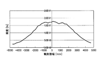
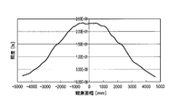
- FIG. 14 is a layout view of the illumination device according to the third embodiment seen through in the optical axis direction. More specifically, four light sources with a radius of 2.5 mm are arranged at equal intervals in the circumferential direction, and the light source portion radius is set to 9.218 mm.
- the refractive index n of the lens is 1.58.
- the material of the lens is glass.
- Table 3 shows lens data (first exit surface and entrance surface). In addition, it has a flat mounting surface separately from the incident surface, and the second emission surface is a simple tapered surface.
- the radius of the light source unit is A and the outer diameter of the lens is B
- a / B 0.554.
- FIG. 15A is a cross-sectional view of the lens of Example 3 in the optical axis direction.
- FIG. 15B is a diagram showing the light distribution characteristics of the lens of Example 3, and graph Y shows the light distribution characteristics in a plane including the optical axis and passing through the center of the two light sources. The light distribution characteristics in a plane perpendicular to the same are shown, and the optical axis is 0 degree.
- FIG.15 (c) is a figure which shows the illumination intensity distribution in the 3000-mm position from the light source of Example 3, and shows that illumination intensity increases as black becomes strong.
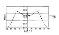
- FIG. 16 is a diagram showing the relationship between the light distribution angle and the luminous intensity in Example 3, where the dotted line is data on the Y plane and the solid line is data on the Z plane.
- Example 17 is a diagram showing a state in which the illuminance changes as it goes to the peripheral side with the optical axis as the center on the irradiated surface when irradiated using the third embodiment. As shown in the figure, Example 3 is also superior to the comparative example.
- Example 4 The illumination device according to Example 4 is the same as the arrangement shown in FIG. Table 4 shows lens data (first exit surface and entrance surface). In addition, it has a flat mounting surface separately from the incident surface, and the second emission surface is a simple tapered surface. However, the refractive index n of the lens is 1.59, and the material of the lens is polycarbonate.
- a / B 0.513.
- FIG. 18A is a cross-sectional view of the lens of Example 4 in the optical axis direction.
- FIG. 18B is a diagram showing the light distribution characteristics of the lens of Example 4, and graph Y shows the light distribution characteristics in a plane that includes the optical axis and passes through the center of one light source. The light distribution characteristics in a plane perpendicular to the same are shown, and the optical axis is 0 degree.
- FIG. 18C is a diagram showing the illuminance distribution at a position of 3000 mm from the light source of Example 4, and shows that the illuminance increases as black becomes stronger.
- FIG. 19 is a diagram illustrating the relationship between the light distribution angle and the luminous intensity in Example 4, where the dotted line is data on the Y plane and the solid line is data on the Z plane.
- Example 20 is a diagram illustrating a state in which the illuminance changes as it goes to the peripheral side with the optical axis as the center on the irradiated surface when irradiated using the fourth embodiment. As shown in the figure, Example 4 is also superior to the comparative example.
- Example 5 The illumination device according to Example 5 is the same as the arrangement shown in FIG. Table 5 shows lens data (first exit surface and entrance surface). In addition, it has a flat mounting surface separately from the incident surface, and the second emission surface is a simple tapered surface. However, the refractive index n of the lens is 1.49, and the material of the lens is PMMA.
- a / B 0.513.
- FIG. 21A is a cross-sectional view of the lens of Example 5 in the optical axis direction.
- FIG. 21B is a diagram showing the light distribution characteristics of the lens of Example 5.
- FIG. 21C is a diagram showing the illuminance distribution at a position of 3000 mm from the light source of Example 5, and shows that the illuminance increases as black becomes stronger.
- FIG. 22 is a diagram illustrating the relationship between the light distribution angle and the luminous intensity in Example 5, where the dotted line is data on the Y plane and the solid line is data on the Z plane.
- Example 23 is a diagram illustrating a state in which the illuminance changes as it goes to the peripheral side with the optical axis as the center on the irradiation surface when irradiation is performed using the fifth embodiment. As shown in the figure, Example 5 is also superior to the comparative example.
- FIG. 24 is a layout view in which the illumination device according to the sixth example is seen through in the optical axis direction. More specifically, three light sources with a radius of 2.4 mm are arranged at equal intervals in the circumferential direction, and the light source part radius is 11.69534 mm.
- the refractive index n of the lens is 1.58.
- the material of the lens is glass.
- Table 6 shows lens data (first exit surface and entrance surface). In addition, it has a flat mounting surface separately from the incident surface, and the second emission surface is a simple tapered surface.
- the radius of the light source unit is A and the outer diameter of the lens is B
- a / B 0.936.
- FIG. 25A is a cross-sectional view of the lens of Example 6 in the optical axis direction.
- FIG. 25B is a diagram illustrating the light distribution characteristics of the lens of Example 6.
- Graph Y includes the optical axis and illustrates the light distribution characteristics in a plane passing through the center of one light source. The light distribution characteristics in a plane perpendicular to the same are shown, and the optical axis is 0 degree.
- FIG. 25C is a diagram showing the illuminance distribution at a position of 3000 mm from the light source of Example 6, and shows that the illuminance increases as black becomes stronger.
- FIG. 25B is a diagram illustrating the light distribution characteristics of the lens of Example 6.
- Graph Y includes the optical axis and illustrates the light distribution characteristics in a plane passing through the center of one light source. The light distribution characteristics in a plane perpendicular to the same are shown, and the optical axis is 0 degree.
- FIG. 25C is a diagram showing the illumina
- Example 26 is a diagram illustrating the relationship between the light distribution angle and the luminous intensity in Example 6, where the dotted line is data on the Y plane and the solid line is data on the Z plane.
- FIG. 27 is a diagram illustrating a state in which the illuminance changes as it goes to the peripheral side with the optical axis as the center on the irradiated surface when irradiated using the sixth embodiment. As shown in the figure, Example 6 is also superior to the comparative example.
- FIG. 28 is a layout view in which the illumination device according to the seventh example is seen through in the optical axis direction. More specifically, two light sources having a radius of 2.5 mm are arranged at equal intervals in the circumferential direction, and the light source portion radius is set to 9.218 mm.
- the refractive index n of the lens is 1.58.
- the material of the lens is glass.
- Table 7 shows lens data (first exit surface and entrance surface). In addition, it has a flat mounting surface separately from the incident surface, and the second emission surface is a simple tapered surface.
- the radius of the light source unit is A and the outer diameter of the lens is B
- a / B 0.554.
- FIG. 29A is a sectional view in the optical axis direction of the lens of Example 7.
- FIG. 29B is a diagram illustrating the light distribution characteristics of the lens of Example 7.
- Graph Y shows the light distribution characteristics in a plane that includes the optical axis and passes through the center of the two light sources. The light distribution characteristics in a plane perpendicular to the same are shown, and the optical axis is 0 degree.
- FIG. 29C is a diagram showing an illuminance distribution at a position of 3000 mm from the light source of Example 7, and shows that the illuminance increases as black becomes stronger.
- FIG. 30 is a diagram illustrating the relationship between the light distribution angle and the light intensity in Example 7, where the dotted line is data on the Y plane and the solid line is data on the Z plane.
- FIG. 31 is a diagram showing a state in which the illuminance changes as it goes to the peripheral side with the optical axis as the center on the irradiated surface when irradiated using the seventh embodiment. As shown in the figure, Example 7 is also superior to the comparative example.
- FIG. 32 is a layout view of the illumination device according to the eighth embodiment seen through in the optical axis direction. More specifically, six light sources having a radius of 1.0 mm are arranged at equal intervals in the circumferential direction, and the light source portion radius is 9 mm.
- the refractive index n of the lens is 1.58.
- the material of the lens is glass.
- Table 8 shows lens data (first exit surface and entrance surface). In addition, it has a flat mounting surface separately from the incident surface, and the second emission surface is a simple tapered surface.
- the radius of the light source unit is A and the outer diameter of the lens is B
- a / B 0.541.
- FIG. 33A is a sectional view of the lens of Example 8 in the optical axis direction.
- FIG. 33B is a diagram showing the light distribution characteristics of the lens of Example 8.
- Graph Y shows the light distribution characteristics in a plane that includes the optical axis and passes through the center of the two light sources. The light distribution characteristics in a plane perpendicular to the same are shown, and the optical axis is 0 degree.
- FIG. 33 (c) is a diagram showing an illuminance distribution at a position of 3000 mm from the light source of Example 8, and shows that the illuminance increases as black becomes stronger.
- FIG. 34 is a diagram illustrating the relationship between the light distribution angle and the luminous intensity in Example 8, where the dotted line is data on the Y plane and the solid line is data on the Z plane.
- FIG. 35 is a diagram showing a state in which the illuminance changes as it goes to the peripheral side with the optical axis as the center on the irradiated surface when irradiated using Example 8. As shown in the figure, Example 8 is also superior to the comparative example.
- FIG. 37A is a sectional view of the lens of Example 9 in the optical axis direction. FIG.
- FIG. 37B is a diagram illustrating the light distribution characteristics of the lens of Example 9, in which the optical axis is 0 degree.
- FIG. 37 (c) is a diagram showing the illuminance distribution at a position of 3000 mm from the light source of Example 9, and shows that the illuminance increases as black becomes stronger.
- FIG. 38 is a diagram illustrating the relationship between the light distribution angle and the light intensity according to the ninth embodiment.
- FIG. 39 is a diagram showing a state in which the illuminance changes as it goes to the peripheral side with the optical axis as the center on the irradiated surface when irradiated using Example 9. As shown in the figure, Example 9 is also superior to the comparative example.
- Example 10 The illumination apparatus according to Example 10 is the same as the arrangement shown in FIG. More specifically, the radius of the light source unit composed of a single light source is 7.7 mm.
- the refractive index n of the lens is 1.58.
- the material of the lens is glass.
- Table 10 shows lens data (first exit surface and entrance surface). In addition, it has a flat mounting surface in addition to the incident surface, and the second exit surface is not a simple tapered surface, but a shape that forms part of a spherical surface with a curvature radius of 16.578 mm.
- FIG. 40A is a sectional view of the lens of Example 10 in the optical axis direction.
- FIG. 40B is a diagram showing the light distribution characteristics of the lens of Example 10, in which the optical axis is 0 degree.
- FIG. 40C is a diagram showing an illuminance distribution at a position of 3000 mm from the light source of Example 10, and shows that the illuminance increases as black becomes stronger.
- FIG. 41 is a diagram illustrating the relationship between the light distribution angle and the light intensity according to the tenth embodiment.
- FIG. 42 is a diagram showing a state in which the illuminance changes as it goes to the peripheral side with the optical axis as the center on the irradiated surface when irradiated using Example 10. As shown in the figure, Example 10 is also superior to the comparative example.
- Example 11 The illumination device according to Example 11 is the same as the arrangement shown in FIG. More specifically, the radius of the light source unit composed of a single light source is 1.5 mm.
- the refractive index n of the lens is 1.58.
- the material of the lens is glass.
- Table 10 shows lens data (first exit surface and entrance surface). In addition, it has a flat mounting surface separately from the incident surface, and the second emission surface is a simple tapered surface.
- the radius of the light source unit is A and the outer diameter of the lens is B
- a / B 0.107.
- FIG. 43A is a sectional view of the lens of Example 11 in the optical axis direction.
- FIG. 43A is a sectional view of the lens of Example 11 in the optical axis direction.
- FIG. 43B is a diagram illustrating the light distribution characteristics of the lens according to Example 11, in which the optical axis is 0 degree.
- FIG. 43C is a diagram showing an illuminance distribution at a position of 3000 mm from the light source of Example 11, and shows that the illuminance increases as black becomes stronger.
- FIG. 44 is a diagram illustrating the relationship between the light distribution angle and the light intensity in Example 11.
- FIG. 45 is a diagram showing a state in which the illuminance changes as it goes to the peripheral side with the optical axis as the center on the irradiated surface when irradiated using Example 11. As shown in the figure, Example 11 is also superior to the comparative example.
- Table 12 summarizes the angles ⁇ and ⁇ (see FIG. 3) in Examples 1 to 11.
- the illumination device eliminates uneven illuminance, so that it is suitable for use in irradiating a plant in a plant factory of a plant (for example, spinach) that is susceptible to light intensity for growth.
- a plant for example, spinach
- Other possible applications include indoor lighting, emergency lighting, backlighting, interior lighting, and sensor applications.
Abstract
Provided are a Lens and an illumination apparatus, wherein a good light distribution can be attained even when using a light source unit the size of which is relatively big compared to the lens, or when using a plurality of light sources. A first radiation-emitting face (OP1) and a second radiation-emitting face (OP2) are configured to have two different types of surface-shapes, and the first radiation-emitting face (OP1) and the second radiation-emitting face (OP2) are linked together such that a first order differential value of the amount of sag (S) will be discontinuous therebetween, and as a result, a light condensing function that was the cause of uneven illuminance is able to be inhibited. That is, an effect of inhibiting uneven illuminance is able to be attained.
Description
本発明は、照度ムラを抑制できる照明装置のレンズ、及びそのレンズを用いた照明装置に関する。
The present invention relates to a lens of an illuminating device that can suppress illuminance unevenness and an illuminating device using the lens.
近年、照明の省エネルギー化や小型化の要求が強まっており、これに伴って蛍光灯を用いた照明に代わり、LED照明が普及し始めている。しかし、LED一つ当たりの光量は蛍光灯に比べ少ないため、特に照度が必要な用途には、一般的に複数のLEDを用いる方法が採られている。
In recent years, demands for energy saving and downsizing of lighting have increased, and LED lighting has started to spread in place of lighting using fluorescent lamps. However, since the amount of light per LED is smaller than that of fluorescent lamps, a method using a plurality of LEDs is generally adopted particularly for applications requiring illuminance.
また、液晶ディスプレイのバックライトにもLEDが採用されつつあるが、そのような用途の場合は、特に照射面における光(照度)のムラが生じないような構成を持つ照明装置が必要とされる。
In addition, LEDs are also being adopted for backlights of liquid crystal displays. In such applications, lighting devices with a configuration that does not cause unevenness of light (illuminance) on the irradiated surface are particularly required. .
バックライトに用いられる照明装置として、特許文献1に示すような照明装置がある。かかる照明装置は、LEDから出射する光の多くが負レンズ様の形状を通過することで適度に拡散させられ、結果的に照度にムラがないようにしている。また、特許文献2に示される照明装置では、それと同様にして光を拡散させることに加え、LEDの発光面からの法線に対し、より大きな角度を有する比較的弱い光を集光させることで、照射面の照度が均一になるようにしている。
There is an illumination device as shown in Patent Document 1 as an illumination device used for a backlight. In such an illuminating device, most of the light emitted from the LED is appropriately diffused by passing through a negative lens-like shape, and as a result, there is no unevenness in illuminance. In addition, in the illumination device shown in Patent Document 2, in addition to diffusing light in the same manner, the relatively weak light having a larger angle with respect to the normal from the light emitting surface of the LED is condensed. The illuminance on the irradiated surface is made uniform.
上記のような構成を取ることで均一な照度を得ることが可能とされているが、どちらの従来技術も、レンズ径に対して光源の大きさが点光源程度のものを想定して設計されている。しかし、LED照明装置の小型化を実現しつつ、必要な照度を確保するためには、一つの光学系に複数のLEDを配置することが好ましいが、特許文献1の技術では複数のLEDに対して適用した場合に、特にレンズ周辺部で照度ムラが発生しやすくなることを、本発明者が見出した。これに対し、複数のLEDを適用した際の当該照度ムラの問題を解決するためには、複数のLEDに対し同数の光学系を用いることで対応できるが、それによりコストが増加してしまうという問題がある。また、特許文献2の技術では、レンズを複数の光源に被せた場合、レンズの側面からの光が照射面に到達するよう設計されていないため、照明効率の低下が問題となる。同様の問題は、比較的大面積の面状発光部を有する光源を単一で用いた場合も生じうる。
Although it is possible to obtain uniform illuminance by taking the configuration as described above, both conventional technologies are designed assuming that the size of the light source is about the point light source with respect to the lens diameter. ing. However, in order to ensure the required illuminance while realizing the downsizing of the LED lighting device, it is preferable to arrange a plurality of LEDs in one optical system. The present inventor has found that uneven illuminance is likely to occur particularly in the periphery of the lens. On the other hand, in order to solve the problem of uneven illuminance when a plurality of LEDs are applied, the same number of optical systems can be used for the plurality of LEDs, but this increases the cost. There's a problem. Moreover, in the technique of patent document 2, when the lens is covered with a plurality of light sources, the light from the side surface of the lens is not designed to reach the irradiation surface, so that a decrease in illumination efficiency becomes a problem. A similar problem may occur when a single light source having a surface light emitting portion having a relatively large area is used.
本発明は、レンズに対する光源部の大きさが比較的大きい場合や複数の光源を用いた場合でも、良好な配光分布を得ることができ、照度ムラを抑制できるレンズ及び照明装置を提供することを目的とする。
The present invention provides a lens and an illuminating device that can obtain a good light distribution even when the size of the light source portion relative to the lens is relatively large or when a plurality of light sources are used, and that can suppress uneven illuminance. With the goal.
請求項1に記載のレンズは、少なくとも一つの光源を含む光源部を有する照明装置に用いられる照明用レンズであって、
前記光源からの光線が入射する入射面と、
光線が出射する出射面を有し、
前記光源部の最大径の半径をA、前記レンズの最大径の半径をBとした時、0.1≦A/B<1を満たし、
前記出射面は、複数の形状式により定義される、少なくとも第一の出射面と第二の出射面とを有し、
前記第一の出射面と前記第二の出射面が、サグ量の一階微分値が不連続になるように繋がっていることを特徴とする。 The lens according toclaim 1 is an illumination lens used in an illumination device having a light source unit including at least one light source,
An incident surface on which light from the light source is incident;
Having an exit surface from which light is emitted;
When the radius of the maximum diameter of the light source unit is A and the radius of the maximum diameter of the lens is B, 0.1 ≦ A / B <1 is satisfied,
The exit surface has at least a first exit surface and a second exit surface defined by a plurality of shape formulas,
The first emission surface and the second emission surface are connected so that the first-order differential value of the sag amount becomes discontinuous.
前記光源からの光線が入射する入射面と、
光線が出射する出射面を有し、
前記光源部の最大径の半径をA、前記レンズの最大径の半径をBとした時、0.1≦A/B<1を満たし、
前記出射面は、複数の形状式により定義される、少なくとも第一の出射面と第二の出射面とを有し、
前記第一の出射面と前記第二の出射面が、サグ量の一階微分値が不連続になるように繋がっていることを特徴とする。 The lens according to
An incident surface on which light from the light source is incident;
Having an exit surface from which light is emitted;
When the radius of the maximum diameter of the light source unit is A and the radius of the maximum diameter of the lens is B, 0.1 ≦ A / B <1 is satisfied,
The exit surface has at least a first exit surface and a second exit surface defined by a plurality of shape formulas,
The first emission surface and the second emission surface are connected so that the first-order differential value of the sag amount becomes discontinuous.
本発明の原理を説明する。図1(a)は、比較例としてのレンズLS’の光軸方向断面図であって、複数の光源から等角度で出射し、レンズLS’を通過して外部に至る光線を示す図であり、図1(b)は、本発明の一例であるレンズLSの光軸方向断面図であって、複数の光源から等角度(配光角5度)で出射し、レンズLSを通過して外部に至る光線を示す図であり、図1(c)、(d)は、照射面RPに検出器をおいて、照射された光の照度を測定した値を濃度で示す図である。入射面は、モデルを単純化すべく光源に接する平面とする。ここで、比較例のレンズは、出射面OPが単一の面形状式により定義されている。一方、本発明の一例にかかるレンズは、光軸周囲の第一の出射面OP1と第二の出射面OP2とを有し、それぞれ二つの異なる面形状式により構成されている。更に、第一の出射面OP1と第二の出射面OP2が、サグ量の一階微分値が不連続になるように繋がっている。これは、第一の出射面OP1と第二の出射面OP2が滑らかに接続されず、交差点CPで交差していることを意味する。
The principle of the present invention will be described. FIG. 1A is a sectional view in the optical axis direction of a lens LS ′ as a comparative example, and shows light rays emitted from a plurality of light sources at an equal angle and passing through the lens LS ′ to the outside. FIG. 1B is a sectional view in the optical axis direction of a lens LS which is an example of the present invention. The lens LS is emitted from a plurality of light sources at an equal angle (light distribution angle of 5 degrees), passes through the lens LS, and is externally transmitted. 1 (c) and 1 (d) are diagrams showing, by concentration, values obtained by measuring the illuminance of the irradiated light with a detector placed on the irradiation surface RP. The entrance surface is a plane in contact with the light source in order to simplify the model. Here, in the lens of the comparative example, the exit surface OP is defined by a single surface shape formula. On the other hand, a lens according to an example of the present invention has a first emission surface OP1 and a second emission surface OP2 around the optical axis, and each is constituted by two different surface shape formulas. Further, the first exit surface OP1 and the second exit surface OP2 are connected so that the first-order differential value of the sag amount becomes discontinuous. This means that the first exit surface OP1 and the second exit surface OP2 are not smoothly connected and intersect at an intersection CP.
まず、比較例のレンズLS’の場合、出射面OPが単一の面形状式により定義されているので、正面から側面へと滑らかにつながって変曲点がない状態である。ここで、光軸Xから離れるにつれて、出射面OPへの光の入射角が次第に大きくなるため、出射光は拡散することとなる。更に出射面OPのサグ量の変化が大きくなり始めると、出射面OPへの入射角は次第に小さくなり、出射面OPの法線が光源を向く位置では、入射角=0°となる。それを境に入射角はまた大きくなり始める。この切り替わり位置(発光位置により異なる)周辺での光線に注目すると、図1(c)に示すように、照射面の一部に光線が集中していることが分かる。つまり照度ムラが生じる原因となっている。
First, in the case of the lens LS ′ of the comparative example, since the exit surface OP is defined by a single surface shape formula, it is smoothly connected from the front to the side and there is no inflection point. Here, as the distance from the optical axis X increases, the incident angle of light on the exit surface OP gradually increases, and thus the exit light diffuses. Further, when the change in the sag amount on the exit surface OP starts to increase, the incident angle on the exit surface OP gradually decreases, and the incident angle = 0 ° at the position where the normal of the exit surface OP faces the light source. The incident angle starts to increase again. When attention is paid to the light rays around this switching position (which differs depending on the light emission position), it can be seen that the light rays are concentrated on a part of the irradiation surface as shown in FIG. That is, this is a cause of uneven illuminance.
これに対し、本発明の一例によるレンズLSでは、図1(b)に示すように、第一の出射面OP1と第二の出射面OP2が、二つの異なる面形状式により構成されており、第一の出射面OP1と第二の出射面OP2が、サグ量Sの一階微分値が不連続になるように繋がっている。比較例であるレンズLS’と比較すると、同様に光線は光軸Xから離れるにつれて拡散するが、その拡散作用は、第一の出射面OP1と第二の出射面OP2が交差する点CPまで有効となっており、その点CPを越えた後も、再び入射角が次第に大きくなっている。よって、入射角が次第に小さくなる範囲が無くなり、入射角が0°になる点も殆ど無くなることになり、図1(d)に示すように、結果として照度ムラの原因となっていた集光作用を抑えることができる。つまり、照度ムラを抑制する効果が得られることとなる。
On the other hand, in the lens LS according to the example of the present invention, as shown in FIG. 1B, the first emission surface OP1 and the second emission surface OP2 are configured by two different surface shape formulas, The first exit surface OP1 and the second exit surface OP2 are connected so that the first-order differential value of the sag amount S is discontinuous. Compared with the lens LS ′ as a comparative example, the light rays are similarly diffused away from the optical axis X, but the diffusion action is effective up to the point CP where the first emission surface OP1 and the second emission surface OP2 intersect. Even after the point CP is exceeded, the incident angle gradually increases again. Therefore, there is no range in which the incident angle gradually decreases, and there is almost no point at which the incident angle becomes 0 °. As shown in FIG. Can be suppressed. That is, the effect of suppressing illuminance unevenness is obtained.
また、複数のLED光源に対して一つのレンズで対応できるため、照明装置一つ当たりに必要となるレンズの個数を低減でき、コストの削減につながる。更に、様々な大きさの光源にもサイズ変更のみで対応できるため、開発のコスト低減と、開発の迅速化を図ることが可能となり、市場の変化に柔軟に対応することが可能となる。
In addition, since a single lens can handle a plurality of LED light sources, the number of lenses required for each lighting device can be reduced, leading to cost reduction. Furthermore, since it is possible to cope with light sources of various sizes only by changing the size, it is possible to reduce development costs and speed up development, and to flexibly respond to changes in the market.
請求項2に記載のレンズは、請求項1に記載の発明において、前記レンズはある軸を中心軸として回転対称の形状を持ち、それを光軸とすることを特徴とする。
The lens according to claim 2 is characterized in that, in the invention according to claim 1, the lens has a rotationally symmetric shape with a certain axis as a central axis, which is an optical axis.
前記レンズを回転対称の形状とすることで、前記光源部からの光線が光軸に対して回転対称に前記第一の出射面と前記第二の出射面から出射し、照度分布が回転対称形状となるので、照明デザイン的にも好ましい。また、レンズ成形性の向上や、前記光源部に対する設置の自由度の向上も図ることが可能である。光源部を含む平面に対して垂直な方向を光軸方向ということもできる。
By forming the lens in a rotationally symmetric shape, light from the light source unit is emitted from the first and second emission surfaces in a rotationally symmetric manner with respect to the optical axis, and the illuminance distribution has a rotationally symmetric shape. Therefore, it is preferable in terms of lighting design. In addition, it is possible to improve the lens moldability and the degree of freedom of installation with respect to the light source unit. The direction perpendicular to the plane including the light source unit can also be referred to as the optical axis direction.
請求項3に記載のレンズは、請求項1又は2に記載の発明において、前記第一の出射面は、凸状の非球面であることを特徴とする。
The lens according to claim 3 is characterized in that, in the invention according to claim 1 or 2, the first emission surface is a convex aspherical surface.
前記第一の出射面を非球面とすることで、前記入射面と組み合わせて光軸上で負のメニスカスレンズのような構成をとることが出来、前記光源部からの光を拡散させることが出来る。また、球面形状に比べてレンズを薄くすることができ、コスト面でも有利である。
By making the first emission surface an aspherical surface, it can be combined with the incident surface to form a negative meniscus lens on the optical axis, and the light from the light source unit can be diffused. . In addition, the lens can be made thinner than the spherical shape, which is advantageous in terms of cost.
請求項4に記載のレンズは、請求項1~3のいずれかに記載の発明において、前記第二の出射面は、テーパ面であることを特徴とする。
The lens according to claim 4 is characterized in that, in the invention according to any one of claims 1 to 3, the second emission surface is a tapered surface.
前記第二の出射面をテーパ面とすることにより、前記光源部から光軸に対して大きな角度をもち、前記第二の出射面に入射する光線も、照射面方向に拡散させながら効率良く出射することができる。更に金型からの離型も行い易くなるという利点もある。尚、テーパ面は光軸(または光軸方向)に対して傾いていることが好ましい。また、テーパ面のうち光源部に近い側が光軸から離れており、光源部から遠い側が光軸に近くなるように傾いていることが好ましい。
By making the second exit surface a tapered surface, a light beam having a large angle with respect to the optical axis from the light source unit and entering the second exit surface can be efficiently emitted while being diffused in the direction of the irradiation surface. can do. Further, there is an advantage that the mold can be easily released from the mold. The tapered surface is preferably inclined with respect to the optical axis (or the optical axis direction). Further, it is preferable that the tapered surface is inclined so that the side closer to the light source part is away from the optical axis and the side far from the light source part is closer to the optical axis.
請求項5に記載のレンズは、請求項1~4のいずれかに記載の発明において、前記光軸近傍の近軸領域において負のパワーをもつことを特徴とする。
The lens according to claim 5 is characterized in that, in the invention according to any one of claims 1 to 4, the lens has a negative power in a paraxial region near the optical axis.
近軸領域で負のパワーを持たせることで、配光がランバーシアン形である光源を用いた場合に前記光源部から出射する光線の内、光軸と平行な比較的強い光成分を拡散させることができ、広い領域をムラなく照らすことが出来る。
By giving a negative power in the paraxial region, a relatively strong light component parallel to the optical axis is diffused among the light rays emitted from the light source unit when a light source having a light distribution of Lambertian is used. Can illuminate a wide area evenly.
請求項6に記載のレンズは、請求項1~5のいずれかに記載の発明において、前記第一の出射面のサグ量は、光軸において光源から光線が出射する方向とは逆の方向を正とした時、光軸から離れるにつれて単調増加することを特徴とする。
According to a sixth aspect of the present invention, in the invention according to any one of the first to fifth aspects, the sag amount of the first emission surface is opposite to the direction in which the light beam is emitted from the light source on the optical axis. When it is positive, it increases monotonically as the distance from the optical axis increases.
前記第一の出射面のサグ量が、光軸から離れるに従って単調増加することで、前記光源部中心(光軸に一致すると好ましい)から出射する光線の、光軸からの角度の増加に伴う前記第一の出射面への入射角の変化が単調増加となり、連続的に光を拡散することが出来る。
The amount of sag of the first emission surface monotonously increases as the distance from the optical axis increases, so that the light emitted from the center of the light source unit (preferably coincident with the optical axis) increases with the angle from the optical axis. The change in the incident angle on the first exit surface monotonously increases, and light can be continuously diffused.
請求項7に記載のレンズは、請求項1~6のいずれかに記載の発明において、前記入射面は、一つの面形状式により構成されることを特徴とする。
The lens according to claim 7 is characterized in that, in the invention according to any one of claims 1 to 6, the incident surface is constituted by one surface shape formula.
前記入射面を単一の非球面式により構成することで、レンズ設計が簡素化され、また成形性の向上を図れる。
The lens design can be simplified and the moldability can be improved by configuring the entrance surface with a single aspherical surface.
請求項8に記載のレンズは、請求項1~7のいずれかに記載の発明において、前記入射面は、前記レンズの取り付け面とは異なる面形状式により構成されることを特徴とする。
The lens according to an eighth aspect of the invention is characterized in that, in the invention according to any one of the first to seventh aspects, the incident surface is constituted by a surface shape formula different from a mounting surface of the lens.
前記入射面は、取り付け面とは異なる面形状式により構成されることで、前記レンズの取り付け面を適切な形状にできる。
The incident surface is configured by a surface shape formula different from the mounting surface, so that the lens mounting surface can be formed into an appropriate shape.
請求項9に記載の照明装置は、請求項1~8のいずれかに記載のレンズと、光源部とを有することを特徴とする。
An illuminating device according to a ninth aspect includes the lens according to any one of the first to eighth aspects and a light source unit.
請求項10に記載の照明装置は、請求項9に記載の発明において、前記光源部は複数の光源を有することを特徴とする。
The illumination device according to claim 10 is characterized in that, in the invention according to claim 9, the light source unit has a plurality of light sources.
単体の光量が低い光源を用いる場合でも、複数の光源を配置することで、全体の光量を稼ぐことができる。また、発光波長の異なる光源を複数用いることで、一つの照明装置から様々な色の照明を得ることが出来る。
Even when a single light source with a low amount of light is used, the entire light amount can be gained by arranging a plurality of light sources. In addition, by using a plurality of light sources having different emission wavelengths, illumination of various colors can be obtained from one illumination device.
請求項11に記載の照明装置は、請求項10に記載の発明において、前記レンズの光軸上に前記光源が存在しないことを特徴とする。
The illumination device according to claim 11 is characterized in that, in the invention according to claim 10, the light source does not exist on the optical axis of the lens.
光軸上に前記光源が存在しない構成をとることで、前記光源を複数個用いた場合、個々の光源が光軸方向に発する強度の強い光を、照射面の周辺部に到達させ、照射面を広く明るく照らすことが出来る。
By adopting a configuration in which the light source does not exist on the optical axis, when a plurality of the light sources are used, strong light emitted from the individual light sources in the optical axis direction reaches the periphery of the irradiation surface, and the irradiation surface Can be illuminated widely and brightly.
請求項12に記載の照明装置は、請求項10に記載の発明において、前記レンズの光軸上に前記光源の一つが存在することを特徴とする。
The illuminating device according to claim 12 is characterized in that, in the invention according to claim 10, one of the light sources exists on the optical axis of the lens.
光軸上に前記光源が存在する構成をとることで、前記光源を複数個用いた場合、光軸近傍の照射面を広く明るく照らすことが出来る。
By adopting a configuration in which the light source exists on the optical axis, when a plurality of the light sources are used, the irradiation surface near the optical axis can be illuminated widely and brightly.
請求項13に記載の照明装置は、請求項9~12のいずれかに記載の発明において、前記光源部の中心は前記レンズの光軸に一致することを特徴とする。
The illuminating device according to claim 13 is characterized in that, in the invention according to any one of claims 9 to 12, the center of the light source unit coincides with the optical axis of the lens.
前記光源部の中心を光軸に一致させることで、照射面を偏りなく照らすことが可能である。
It is possible to illuminate the irradiated surface evenly by making the center of the light source unit coincide with the optical axis.
請求項14に記載の照明装置は、請求項9~13のいずれかに記載の発明において、前記光源部は面状発光光源であることを特徴とする。
The illumination device according to claim 14 is characterized in that, in the invention according to any one of claims 9 to 13, the light source section is a planar light source.
前記光源に面状発光光源を用いることで照明装置の薄型化を図ることが可能である。
It is possible to reduce the thickness of the lighting device by using a planar light source as the light source.
請求項15に記載の照明装置は、請求項9~14のいずれかに記載の発明において、前記光源部内の光源は、前記レンズの光軸に対し回転対称に配置されることを特徴とする。
The illumination device according to claim 15 is characterized in that, in the invention according to any one of claims 9 to 14, the light source in the light source section is arranged rotationally symmetrically with respect to the optical axis of the lens.
前記光源を光軸の回転対称に配置することで、複数種類の光源をそれぞれ複数個配置した際に、均一な光の混合を行うことが出来る。
By arranging the light sources so as to be rotationally symmetric with respect to the optical axis, uniform light mixing can be performed when a plurality of types of light sources are arranged.
光源としては、LED(Light-Emitting Diode)やOLED(Organic Light-Emitting Diode)等の面状発光素子が好ましく、特に光学素子側の面がフラットであることが望ましく、更には表面実装型が望ましい。
The light source is preferably a planar light emitting element such as an LED (Light-Emitting Diode) or OLED (Organic Light-Emitting Diode), and the surface on the optical element side is particularly flat, and more preferably a surface-mount type. .
レンズの素材としては、プラスチック、ガラス、シリコン系樹脂、ウレタン系樹脂、オレフィン系樹脂、ゲル等を用いることができる。
As the lens material, plastic, glass, silicon-based resin, urethane-based resin, olefin-based resin, gel, or the like can be used.
サグ量とは、出射面頂点から出射面上の任意の点までの光軸方向の距離である。
The sag amount is the distance in the optical axis direction from the vertex of the exit surface to any point on the exit surface.
図2(a)に示すように、光源部を複数の光源を用いて構成した場合、全ての光源の発光部OSに外接する最小の円C1の直径φを光源部の直径とし、図2(b)に示すように、一つの光源を用いた場合、その発光部OSの直径φを光源部の直径とする。また、図2(c)に示すように、発光部が円形でない場合(四角形、楕円形等)は、発光部の中心から最も遠い発光部OSの端部を通過する円C2の直径φを光源部の直径とする。
As shown in FIG. 2A, when the light source unit is configured using a plurality of light sources, the diameter φ of the smallest circle C1 circumscribing the light emitting units OS of all the light sources is defined as the diameter of the light source unit. As shown in b), when one light source is used, the diameter φ of the light emitting unit OS is set as the diameter of the light source unit. Further, as shown in FIG. 2C, when the light emitting part is not circular (square, elliptical, etc.), the diameter φ of the circle C2 passing through the end of the light emitting part OS farthest from the center of the light emitting part is set as the light source. The diameter of the part.
レンズの最大径は、レンズが円形でない場合(Dカット、四角形等)、光軸から垂直方向における最も遠いレンズ端部(光学的に有効な部分)に外接する円の直径とする。
The maximum lens diameter is the diameter of a circle circumscribing the farthest lens end (optically effective portion) in the vertical direction from the optical axis when the lens is not circular (D cut, square, etc.).
設計時に、第一の出射面と第二の出射面が、サグ量の一階微分値が不連続になって繋がるように設計したとしても、製造時に連続になってしまうことはあり得るが、そのような成形品であっても、製造誤差の範囲であれば本発明の効果は得られる。製造誤差の範囲と見なせる範囲としては、例えば、第一の出射面と第二の出射面のつなぎ部分の局所的な曲率半径がR=100μm以下である場合も、サグ量の一階微分値が不連続とみなすことができる。
Even if it is designed so that the first exit surface and the second exit surface are connected so that the first-order differential value of the sag amount becomes discontinuous at the time of design, it may be continuous at the time of manufacture, Even for such a molded product, the effects of the present invention can be obtained within the range of manufacturing errors. As a range that can be regarded as a range of manufacturing error, for example, even when the local radius of curvature of the connecting portion between the first emission surface and the second emission surface is R = 100 μm or less, the first-order differential value of the sag amount is It can be regarded as discontinuous.
本発明によれば、レンズに対する光源部の大きさが比較的大きい場合や複数の光源を用いた場合でも、良好な配光分布を得ることができ、照度ムラを抑制できるレンズ及び照明装置を提供することができる。
According to the present invention, it is possible to provide a lens and an illumination device that can obtain a good light distribution and suppress uneven illuminance even when the size of the light source unit with respect to the lens is relatively large or when a plurality of light sources are used. can do.
以下、本発明の実施の形態を、図面を参照して説明する。図3は、本実施の形態における照明装置の光軸方向断面図である。図3において、照明装置は光源部OSPとレンズLSとからなる。不図示の基板に形成された複数のLEDからなる光源部OSPは、その外接円の輪郭のみを図示しており、発光面EPを上方に向けている。外内面共に光軸中心回りに回転対称形状であるレンズLSは、ガラス又は樹脂からなり、その内部空間に光源部OSPを配置しており、両者間に空気が介在している。
Hereinafter, embodiments of the present invention will be described with reference to the drawings. FIG. 3 is a cross-sectional view in the optical axis direction of the lighting apparatus according to the present embodiment. In FIG. 3, the illumination device includes a light source unit OSP and a lens LS. The light source unit OSP formed of a plurality of LEDs formed on a substrate (not shown) shows only the outline of the circumscribed circle, and the light emitting surface EP faces upward. The lens LS, which has a rotationally symmetric shape around the optical axis center on both the outer and inner surfaces, is made of glass or resin, has a light source part OSP disposed in the inner space, and air is interposed therebetween.
図3に示すように、レンズLSの光軸をXとし、光軸Xは光源部OSPの中心と一致する。レンズLSは、取り付け面SPと、発光面EPから出射された光線を入射するレンズLSの内面を入射面IPと、入射面IPから入射した光線を出射する外面を出射面を有するが、かかる出射面は、光軸Xに近い側の第一の出射面OP1と、光軸Xから遠い側の第二の出射面OP2とからなる。更に、不図示の基板に取り付けるための取り付け面SPが設けられている。尚、凸状の非球面であると好ましい第一の出射面OP1と、第二の出射面OP2は、互いに異なる面形状式で定義される。又、第一の出射面OP1と第二の出射面OP2が、交差点CPにてサグ量の一階微分値が不連続になるように繋がっている。第一の出射面OP1のサグ量は、光軸Xにおいては光源部OSPから光線が出射する方向とは逆の方向を正とした時、光軸から離れるにつれて単調増加すると好ましい。又、レンズLSは、光軸近傍の近軸領域において負のパワーをもつと好ましい。
As shown in FIG. 3, the optical axis of the lens LS is X, and the optical axis X coincides with the center of the light source unit OSP. The lens LS has an attachment surface SP, an inner surface of the lens LS that receives light emitted from the light emitting surface EP, an incident surface IP, and an outer surface that emits light incident from the incident surface IP. The surface includes a first emission surface OP1 on the side close to the optical axis X and a second emission surface OP2 on the side far from the optical axis X. Further, an attachment surface SP for attaching to a substrate (not shown) is provided. The first exit surface OP1 and the second exit surface OP2 that are preferably convex aspheric surfaces are defined by different surface shape formulas. Further, the first exit surface OP1 and the second exit surface OP2 are connected so that the first-order differential value of the sag amount becomes discontinuous at the intersection CP. The sag amount of the first exit surface OP1 preferably increases monotonously with increasing distance from the optical axis when the direction opposite to the direction in which the light beam exits from the light source unit OSP is positive in the optical axis X. The lens LS preferably has negative power in the paraxial region near the optical axis.
ここで、図3に示す光軸方向断面図において、光源部OSPの発光面EPの中心Cと、交差点CPとを通過する線L1と、光軸Xとのなす角をαとし、光源部OSPの発光面EPの縁Pと、交差点CPとを通過する線L2と、光軸Xとのなす角をβとすると、以下の式を満たすと好ましい。
50°≦α≦80° (1)
0°≦β≦80° (2)
より好ましくは以下の式を満たすことである。
0°≦β≦60° (2´) Here, in the sectional view in the optical axis direction shown in FIG. 3, the angle formed by the optical axis X and the line L1 passing through the center C of the light emitting surface EP of the light source part OSP and the intersection CP is α, and the light source part OSP. When the angle formed by the optical axis X and the line L2 passing through the edge P of the light emitting surface EP and the intersection CP is β, it is preferable that the following expression is satisfied.
50 ° ≦ α ≦ 80 ° (1)
0 ° ≦ β ≦ 80 ° (2)
More preferably, the following formula is satisfied.
0 ° ≦ β ≦ 60 ° (2 ')
次に、比較例と実施例について説明する。以下に述べる実施例に記載のレンズは全て、出射面が二面以上の面形状式により構成され、それぞれの面の接合部はサグ量の一階微分値が不連続となっている。尚、これ以降(表のレンズデータ含む)において、10のべき乗数(例えば、2.5×10⁻³)を、E(例えば、2.5×E-3)を用いて表す場合がある。また、レンズの入射面及び出射面は、それぞれ数1式に表に示す係数を代入した数式で規定される、光軸の周りに軸対称な非球面に形成されている。
Next, comparative examples and examples will be described. All the lenses described in the embodiments described below are configured by a surface shape formula having two or more exit surfaces, and the first-order differential value of the sag amount is discontinuous at the joint portion of each surface. In the following (including the lens data in the table), a power of 10 (for example, 2.5 × 10 −3 ) may be expressed using E (for example, 2.5 × E−3). In addition, the entrance surface and the exit surface of the lens are each formed as an aspherical surface that is symmetric about the optical axis and is defined by a mathematical formula in which the coefficients shown in the table are substituted into Equation (1).

ここで、X(h)は光軸方向の軸(光の進行方向を正とする)、κは円錐係数、Aiは非球面係数、hは光軸からの高さ、rは近軸曲率半径である。
Here, X (h) is an axis in the optical axis direction (with the light traveling direction being positive), κ is a conical coefficient, Ai is an aspherical coefficient, h is a height from the optical axis, and r is a paraxial radius of curvature. It is.
(実施例1)
図4は、実施例1にかかる照明装置を光軸方向に透視した配置図である。より具体的には、半径2.5mmの光源を周方向に等間隔で(回転対称に)3個配置し、光源部半径を7.696mmとしている。レンズの屈折率nは1.58である。レンズの素材はガラスである。表1に、レンズのデータ(第一の出射面と入射面)を示す。尚、入射面とは別に平面(つまり、面形状式が異なる面)の取り付け面を有し、第二の出射面は、単純なテーパ面である。ここで、光源部の半径をAとし、レンズの外径をBとすると、A/B=0.513である。図5(a)は、実施例1のレンズの光軸方向断面図である。図5(b)は、実施例1のレンズの配光特性を示す図であり、グラフYは光軸を含み、1つの光源の中央を通る面(Y面という、以下同じ)内における配光特性を示し、グラフZは、それに直交する面(Z面という、以下同じ)内における配光特性を示し、光軸を0度としている。
図5(c)は、実施例1の光源から3000mmの位置における照度分布を示す図であり、黒色が強くなるに連れて照度が増大することを示す。図6は、実施例1の配光角と光度との関係を示す図であり、点線がY面のデータであり、実線がZ面のデータである。図7は、実施例1を用いて照射した場合に、照射面において光軸を中心として周辺側に行くに従い照度が変化する状態を示す図である。 Example 1
FIG. 4 is a layout view of the illumination device according to the first embodiment seen through in the optical axis direction. More specifically, three light sources with a radius of 2.5 mm are arranged at equal intervals (rotationally symmetric) in the circumferential direction, and the light source part radius is 7.696 mm. The refractive index n of the lens is 1.58. The material of the lens is glass. Table 1 shows lens data (first exit surface and entrance surface). In addition, it has a flat (that is, a surface having a different surface shape) attachment surface separately from the incident surface, and the second exit surface is a simple tapered surface. Here, assuming that the radius of the light source unit is A and the outer diameter of the lens is B, A / B = 0.513. FIG. 5A is a cross-sectional view of the lens of Example 1 in the optical axis direction. FIG. 5B is a diagram illustrating the light distribution characteristics of the lens of Example 1. The graph Y includes the optical axis and distributes light within a plane passing through the center of one light source (hereinafter referred to as the Y plane). The graph Z shows the light distribution characteristic in a plane orthogonal to the graph (hereinafter referred to as Z plane), and the optical axis is 0 degree.
FIG.5 (c) is a figure which shows the illumination intensity distribution in the 3000-mm position from the light source of Example 1, and shows that illumination intensity increases as black becomes strong. FIG. 6 is a diagram illustrating the relationship between the light distribution angle and the light intensity in Example 1, in which the dotted line is data on the Y plane and the solid line is data on the Z plane. FIG. 7 is a diagram illustrating a state in which the illuminance changes as it goes to the peripheral side with the optical axis as the center on the irradiated surface when irradiation is performed using the first embodiment.

(比較例)
比較例にかかる照明装置は、図4に示す配置と同様である。本比較例では、実施例1を非球面でフィットし、出射面を1つの非球面式で表している。入射面は共通である。ここで、光源部の半径をAとし、レンズの外径をBとすると、A/B=0.513である。レンズの屈折率は実施例1と同じである。レンズの素材はガラスである。図8(a)は、比較例のレンズの光軸方向断面図である。図8(b)は、比較例のレンズの配光特性を示す図であり、グラフYは、光軸を含み、1つの光源の中央を通る面内における配光特性を示し、グラフZは、それに直交する面内における配光特性を示し、光軸を0度としている。
図8(c)は、比較例の光源から3000mmの位置における照度分布を示す図であり、黒色が強くなるに連れて照度が増大することを示す。図9は、比較例の配光角と光度との関係を示す図であり、点線がY面のデータであり、実線がZ面のデータである。図10は、比較例を用いて照射した場合に、照射面において光軸を中心として周辺側に行くに従い照度が変化する状態を示す図である。 (Comparative example)
The illumination device according to the comparative example is the same as the arrangement shown in FIG. In this comparative example, Example 1 is fitted with an aspheric surface, and the exit surface is represented by one aspherical expression. The incident surface is common. Here, assuming that the radius of the light source unit is A and the outer diameter of the lens is B, A / B = 0.513. The refractive index of the lens is the same as in Example 1. The material of the lens is glass. FIG. 8A is a cross-sectional view in the optical axis direction of the lens of the comparative example. FIG. 8B is a diagram showing the light distribution characteristics of the lens of the comparative example. Graph Y shows the light distribution characteristics in a plane including the optical axis and passing through the center of one light source. The light distribution characteristics in a plane perpendicular to the same are shown, and the optical axis is 0 degree.
FIG.8 (c) is a figure which shows the illumination intensity distribution in the 3000-mm position from the light source of a comparative example, and shows that illumination intensity increases as black becomes strong. FIG. 9 is a diagram illustrating the relationship between the light distribution angle and the luminous intensity of the comparative example, in which the dotted line is data on the Y plane, and the solid line is data on the Z plane. FIG. 10 is a diagram showing a state in which the illuminance changes as it goes to the peripheral side with the optical axis as the center on the irradiated surface when irradiated using the comparative example.
比較例では、図8(b)に示すグラフY,Zがずれているように、方向により照度分布が異なり、また図8(c)で中心から3方向に突出するように照射分布強度が不均一となっており、更に図9に示すように、±50度付近に照度のピークが生じ、加えて図10に示すように、光軸から周辺側に向かうに連れていく途中で、照度が増大する箇所があるので、照明装置としては適切でない。
In the comparative example, the illuminance distribution varies depending on the direction as shown in the graphs Y and Z shown in FIG. 8B, and the irradiation distribution intensity is not so high as to protrude in the three directions from the center in FIG. 8C. Further, as shown in FIG. 9, a peak of illuminance occurs in the vicinity of ± 50 degrees as shown in FIG. 9, and in addition, as shown in FIG. 10, the illuminance is on the way from the optical axis toward the peripheral side. Since there is a part where it increases, it is not suitable as a lighting device.
これに対し実施例1では、図5(b)に示すグラフA,Bがほぼ一致し、また図5(c)で中心より点対称に照射分布強度が均一となっており、更に図6に示すように、±50度付近に照度のピークが抑制され、加えて図7に示すように、光軸から周辺側に向かうに連れていく途中で照度が漸次低下するので、照明装置としては適切である。尚、複数の光源を用いる場合、レンズの光軸が1つの光源を通過するように配置しても良い。
On the other hand, in Example 1, the graphs A and B shown in FIG. 5B almost coincide, and in FIG. 5C, the irradiation distribution intensity is uniform with point symmetry from the center. As shown in the figure, the peak of illuminance is suppressed around ± 50 degrees, and in addition, as shown in FIG. 7, the illuminance gradually decreases on the way from the optical axis toward the peripheral side. It is. In addition, when using a some light source, you may arrange | position so that the optical axis of a lens may pass one light source.
(実施例2)
実施例2にかかる照明装置は、図4に示す配置と同様である。表2に、レンズのデータ(第一の出射面と入射面)を示す。本実施例では、入射面と取り付け面とを1つの非球面式で表している。尚、第二の出射面は、単純なテーパ面である。ここで、光源部の半径をAとし、レンズの外径をBとすると、A/B=0.513である。レンズの屈折率nは1.58である。レンズの素材はガラスである。図11(a)は、実施例2のレンズの光軸方向断面図である。図11(b)は、実施例2のレンズの配光特性を示す図であり、グラフYは光軸を含み、1つの光源の中央を通る面内における配光特性を示し、グラフZは、それに直交する面内における配光特性を示し、光軸を0度としている。図11(c)は、実施例2の光源から3000mmの位置における照度分布を示す図であり、黒色が強くなるに連れて照度が増大することを示す。図12は、実施例2の配光角と光度との関係を示す図であり、点線がY面のデータであり、実線がZ面のデータである。図13は、実施例2を用いて照射した場合に、照射面において光軸を中心として周辺側に行くに従い照度が変化する状態を示す図である。図に示すように、実施例2も比較例より優れている。 (Example 2)
The illumination device according to Example 2 is the same as the arrangement shown in FIG. Table 2 shows lens data (first exit surface and entrance surface). In this embodiment, the incident surface and the mounting surface are represented by one aspherical expression. The second emission surface is a simple tapered surface. Here, assuming that the radius of the light source unit is A and the outer diameter of the lens is B, A / B = 0.513. The refractive index n of the lens is 1.58. The material of the lens is glass. FIG. 11A is a cross-sectional view of the lens of Example 2 in the optical axis direction. FIG.11 (b) is a figure which shows the light distribution characteristic of the lens of Example 2, the graph Y contains the optical axis, shows the light distribution characteristic in the plane which passes along the center of one light source, and the graph Z shows The light distribution characteristics in a plane perpendicular to the same are shown, and the optical axis is 0 degree. FIG.11 (c) is a figure which shows the illumination intensity distribution in the 3000-mm position from the light source of Example 2, and shows that illumination intensity increases as black becomes strong. FIG. 12 is a diagram illustrating the relationship between the light distribution angle and the luminous intensity in Example 2, where the dotted line is data on the Y plane and the solid line is data on the Z plane. FIG. 13 is a diagram illustrating a state in which the illuminance changes as it goes to the peripheral side with the optical axis as the center on the irradiated surface when irradiated using the second embodiment. As shown in the figure, Example 2 is also superior to the comparative example.

(実施例3)
図14は、実施例3にかかる照明装置を光軸方向に透視した配置図である。より具体的には、半径2.5mmの光源を周方向に等間隔で4個配置し、光源部半径を9.218mmとしている。レンズの屈折率nは1.58である。レンズの素材はガラスである。表3に、レンズのデータ(第一の出射面と入射面)を示す。尚、入射面とは別に平面の取り付け面を有し、第二の出射面は、単純なテーパ面である。ここで、光源部の半径をAとし、レンズの外径をBとすると、A/B=0.554である。図15(a)は、実施例3のレンズの光軸方向断面図である。図15(b)は、実施例3のレンズの配光特性を示す図であり、グラフYは光軸を含み、2つの光源の中央を通る面内における配光特性を示し、グラフZは、それに直交する面内における配光特性を示し、光軸を0度としている。図15(c)は、実施例3の光源から3000mmの位置における照度分布を示す図であり、黒色が強くなるに連れて照度が増大することを示す。図16は、実施例3の配光角と光度との関係を示す図であり、点線がY面のデータであり、実線がZ面のデータである。図17は、実施例3を用いて照射した場合に、照射面において光軸を中心として周辺側に行くに従い照度が変化する状態を示す図である。図に示すように、実施例3も比較例より優れている。 (Example 3)
FIG. 14 is a layout view of the illumination device according to the third embodiment seen through in the optical axis direction. More specifically, four light sources with a radius of 2.5 mm are arranged at equal intervals in the circumferential direction, and the light source portion radius is set to 9.218 mm. The refractive index n of the lens is 1.58. The material of the lens is glass. Table 3 shows lens data (first exit surface and entrance surface). In addition, it has a flat mounting surface separately from the incident surface, and the second emission surface is a simple tapered surface. Here, assuming that the radius of the light source unit is A and the outer diameter of the lens is B, A / B = 0.554. FIG. 15A is a cross-sectional view of the lens of Example 3 in the optical axis direction. FIG. 15B is a diagram showing the light distribution characteristics of the lens of Example 3, and graph Y shows the light distribution characteristics in a plane including the optical axis and passing through the center of the two light sources. The light distribution characteristics in a plane perpendicular to the same are shown, and the optical axis is 0 degree. FIG.15 (c) is a figure which shows the illumination intensity distribution in the 3000-mm position from the light source of Example 3, and shows that illumination intensity increases as black becomes strong. FIG. 16 is a diagram showing the relationship between the light distribution angle and the luminous intensity in Example 3, where the dotted line is data on the Y plane and the solid line is data on the Z plane. FIG. 17 is a diagram showing a state in which the illuminance changes as it goes to the peripheral side with the optical axis as the center on the irradiated surface when irradiated using the third embodiment. As shown in the figure, Example 3 is also superior to the comparative example.
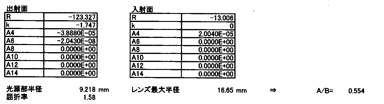
(実施例4)
実施例4にかかる照明装置は、図4に示す配置と同様である。表4に、レンズのデータ(第一の出射面と入射面)を示す。尚、入射面とは別に平面の取り付け面を有し、第二の出射面は、単純なテーパ面である。但し、レンズの屈折率nは1.59であり、レンズの素材はポリカーボネートである。ここで、光源部の半径をAとし、レンズの外径をBとすると、A/B=0.513である。図18(a)は、実施例4のレンズの光軸方向断面図である。図18(b)は、実施例4のレンズの配光特性を示す図であり、グラフYは光軸を含み、1つの光源の中央を通る面内における配光特性を示し、グラフZは、それに直交する面内における配光特性を示し、光軸を0度としている。図18(c)は、実施例4の光源から3000mmの位置における照度分布を示す図であり、黒色が強くなるに連れて照度が増大することを示す。図19は、実施例4の配光角と光度との関係を示す図であり、点線がY面のデータであり、実線がZ面のデータである。図20は、実施例4を用いて照射した場合に、照射面において光軸を中心として周辺側に行くに従い照度が変化する状態を示す図である。図に示すように、実施例4も比較例より優れている。 Example 4
The illumination device according to Example 4 is the same as the arrangement shown in FIG. Table 4 shows lens data (first exit surface and entrance surface). In addition, it has a flat mounting surface separately from the incident surface, and the second emission surface is a simple tapered surface. However, the refractive index n of the lens is 1.59, and the material of the lens is polycarbonate. Here, assuming that the radius of the light source unit is A and the outer diameter of the lens is B, A / B = 0.513. FIG. 18A is a cross-sectional view of the lens of Example 4 in the optical axis direction. FIG. 18B is a diagram showing the light distribution characteristics of the lens of Example 4, and graph Y shows the light distribution characteristics in a plane that includes the optical axis and passes through the center of one light source. The light distribution characteristics in a plane perpendicular to the same are shown, and the optical axis is 0 degree. FIG. 18C is a diagram showing the illuminance distribution at a position of 3000 mm from the light source of Example 4, and shows that the illuminance increases as black becomes stronger. FIG. 19 is a diagram illustrating the relationship between the light distribution angle and the luminous intensity in Example 4, where the dotted line is data on the Y plane and the solid line is data on the Z plane. FIG. 20 is a diagram illustrating a state in which the illuminance changes as it goes to the peripheral side with the optical axis as the center on the irradiated surface when irradiated using the fourth embodiment. As shown in the figure, Example 4 is also superior to the comparative example.

(実施例5)
実施例5にかかる照明装置は、図4に示す配置と同様である。表5に、レンズのデータ(第一の出射面と入射面)を示す。尚、入射面とは別に平面の取り付け面を有し、第二の出射面は、単純なテーパ面である。但し、レンズの屈折率nは、1.49であり、レンズの素材はPMMAである。ここで、光源部の半径をAとし、レンズの外径をBとすると、A/B=0.513である。図21(a)は、実施例5のレンズの光軸方向断面図である。図21(b)は、実施例5のレンズの配光特性を示す図であり、グラフYは光軸を含み、1つの光源の中央を通る面内における配光特性を示し、グラフZは、それに直交する面内における配光特性を示し、光軸を0度としている。図21(c)は、実施例5の光源から3000mmの位置における照度分布を示す図であり、黒色が強くなるに連れて照度が増大することを示す。図22は、実施例5の配光角と光度との関係を示す図であり、点線がY面のデータであり、実線がZ面のデータである。図23は、実施例5を用いて照射した場合に、照射面において光軸を中心として周辺側に行くに従い照度が変化する状態を示す図である。図に示すように、実施例5も比較例より優れている。 (Example 5)
The illumination device according to Example 5 is the same as the arrangement shown in FIG. Table 5 shows lens data (first exit surface and entrance surface). In addition, it has a flat mounting surface separately from the incident surface, and the second emission surface is a simple tapered surface. However, the refractive index n of the lens is 1.49, and the material of the lens is PMMA. Here, assuming that the radius of the light source unit is A and the outer diameter of the lens is B, A / B = 0.513. FIG. 21A is a cross-sectional view of the lens of Example 5 in the optical axis direction. FIG. 21B is a diagram showing the light distribution characteristics of the lens of Example 5. Graph Y shows the light distribution characteristics in a plane that includes the optical axis and passes through the center of one light source. The light distribution characteristics in a plane perpendicular to the same are shown, and the optical axis is 0 degree. FIG. 21C is a diagram showing the illuminance distribution at a position of 3000 mm from the light source of Example 5, and shows that the illuminance increases as black becomes stronger. FIG. 22 is a diagram illustrating the relationship between the light distribution angle and the luminous intensity in Example 5, where the dotted line is data on the Y plane and the solid line is data on the Z plane. FIG. 23 is a diagram illustrating a state in which the illuminance changes as it goes to the peripheral side with the optical axis as the center on the irradiation surface when irradiation is performed using the fifth embodiment. As shown in the figure, Example 5 is also superior to the comparative example.
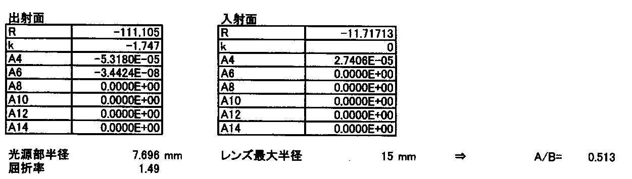
(実施例6)
図24は、実施例6にかかる照明装置を光軸方向に透視した配置図である。より具体的には、半径2.4mmの光源を周方向に等間隔で3個配置し、光源部半径を11.69534mmとしている。レンズの屈折率nは1.58である。レンズの素材はガラスである。表6に、レンズのデータ(第一の出射面と入射面)を示す。尚、入射面とは別に平面の取り付け面を有し、第二の出射面は、単純なテーパ面である。ここで、光源部の半径をAとし、レンズの外径をBとすると、A/B=0.936である。図25(a)は、実施例6のレンズの光軸方向断面図である。図25(b)は、実施例6のレンズの配光特性を示す図であり、グラフYは光軸を含み、1つの光源の中央を通る面内における配光特性を示し、グラフZは、それに直交する面内における配光特性を示し、光軸を0度としている。
図25(c)は、実施例6の光源から3000mmの位置における照度分布を示す図であり、黒色が強くなるに連れて照度が増大することを示す。図26は、実施例6の配光角と光度との関係を示す図であり、点線がY面のデータであり、実線がZ面のデータである。
図27は、実施例6を用いて照射した場合に、照射面において光軸を中心として周辺側に行くに従い照度が変化する状態を示す図である。図に示すように、実施例6も比較例より優れている。 (Example 6)
FIG. 24 is a layout view in which the illumination device according to the sixth example is seen through in the optical axis direction. More specifically, three light sources with a radius of 2.4 mm are arranged at equal intervals in the circumferential direction, and the light source part radius is 11.69534 mm. The refractive index n of the lens is 1.58. The material of the lens is glass. Table 6 shows lens data (first exit surface and entrance surface). In addition, it has a flat mounting surface separately from the incident surface, and the second emission surface is a simple tapered surface. Here, assuming that the radius of the light source unit is A and the outer diameter of the lens is B, A / B = 0.936. FIG. 25A is a cross-sectional view of the lens of Example 6 in the optical axis direction. FIG. 25B is a diagram illustrating the light distribution characteristics of the lens of Example 6. Graph Y includes the optical axis and illustrates the light distribution characteristics in a plane passing through the center of one light source. The light distribution characteristics in a plane perpendicular to the same are shown, and the optical axis is 0 degree.
FIG. 25C is a diagram showing the illuminance distribution at a position of 3000 mm from the light source of Example 6, and shows that the illuminance increases as black becomes stronger. FIG. 26 is a diagram illustrating the relationship between the light distribution angle and the luminous intensity in Example 6, where the dotted line is data on the Y plane and the solid line is data on the Z plane.
FIG. 27 is a diagram illustrating a state in which the illuminance changes as it goes to the peripheral side with the optical axis as the center on the irradiated surface when irradiated using the sixth embodiment. As shown in the figure, Example 6 is also superior to the comparative example.

(実施例7)
図28は、実施例7にかかる照明装置を光軸方向に透視した配置図である。より具体的には、半径2.5mmの光源を周方向に等間隔で2個配置し、光源部半径を9.218mmとしている。レンズの屈折率nは1.58である。レンズの素材はガラスである。表7に、レンズのデータ(第一の出射面と入射面)を示す。尚、入射面とは別に平面の取り付け面を有し、第二の出射面は、単純なテーパ面である。ここで、光源部の半径をAとし、レンズの外径をBとすると、A/B=0.554である。図29(a)は、実施例7のレンズの光軸方向断面図である。図29(b)は、実施例7のレンズの配光特性を示す図であり、グラフYは光軸を含み、2つの光源の中央を通る面内における配光特性を示し、グラフZは、それに直交する面内における配光特性を示し、光軸を0度としている。図29(c)は、実施例7の光源から3000mmの位置における照度分布を示す図であり、黒色が強くなるに連れて照度が増大することを示す。図30は、実施例7の配光角と光度との関係を示す図であり、点線がY面のデータであり、実線がZ面のデータである。図31は、実施例7を用いて照射した場合に、照射面において光軸を中心として周辺側に行くに従い照度が変化する状態を示す図である。図に示すように、実施例7も比較例より優れている。 (Example 7)
FIG. 28 is a layout view in which the illumination device according to the seventh example is seen through in the optical axis direction. More specifically, two light sources having a radius of 2.5 mm are arranged at equal intervals in the circumferential direction, and the light source portion radius is set to 9.218 mm. The refractive index n of the lens is 1.58. The material of the lens is glass. Table 7 shows lens data (first exit surface and entrance surface). In addition, it has a flat mounting surface separately from the incident surface, and the second emission surface is a simple tapered surface. Here, assuming that the radius of the light source unit is A and the outer diameter of the lens is B, A / B = 0.554. FIG. 29A is a sectional view in the optical axis direction of the lens of Example 7. FIG. FIG. 29B is a diagram illustrating the light distribution characteristics of the lens of Example 7. Graph Y shows the light distribution characteristics in a plane that includes the optical axis and passes through the center of the two light sources. The light distribution characteristics in a plane perpendicular to the same are shown, and the optical axis is 0 degree. FIG. 29C is a diagram showing an illuminance distribution at a position of 3000 mm from the light source of Example 7, and shows that the illuminance increases as black becomes stronger. FIG. 30 is a diagram illustrating the relationship between the light distribution angle and the light intensity in Example 7, where the dotted line is data on the Y plane and the solid line is data on the Z plane. FIG. 31 is a diagram showing a state in which the illuminance changes as it goes to the peripheral side with the optical axis as the center on the irradiated surface when irradiated using the seventh embodiment. As shown in the figure, Example 7 is also superior to the comparative example.

(実施例8)
図32は、実施例8にかかる照明装置を光軸方向に透視した配置図である。より具体的には、半径1.0mmの光源を周方向に等間隔で6個配置し、光源部半径を9mmとしている。レンズの屈折率nは1.58である。レンズの素材はガラスである。表8に、レンズのデータ(第一の出射面と入射面)を示す。尚、入射面とは別に平面の取り付け面を有し、第二の出射面は、単純なテーパ面である。ここで、光源部の半径をAとし、レンズの外径をBとすると、A/B=0.541である。図33(a)は、実施例8のレンズの光軸方向断面図である。図33(b)は、実施例8のレンズの配光特性を示す図であり、グラフYは光軸を含み、2つの光源の中央を通る面内における配光特性を示し、グラフZは、それに直交する面内における配光特性を示し、光軸を0度としている。図33(c)は、実施例8の光源から3000mmの位置における照度分布を示す図であり、黒色が強くなるに連れて照度が増大することを示す。図34は、実施例8の配光角と光度との関係を示す図であり、点線がY面のデータであり、実線がZ面のデータである。図35は、実施例8を用いて照射した場合に、照射面において光軸を中心として周辺側に行くに従い照度が変化する状態を示す図である。図に示すように、実施例8も比較例より優れている。 (Example 8)
FIG. 32 is a layout view of the illumination device according to the eighth embodiment seen through in the optical axis direction. More specifically, six light sources having a radius of 1.0 mm are arranged at equal intervals in the circumferential direction, and the light source portion radius is 9 mm. The refractive index n of the lens is 1.58. The material of the lens is glass. Table 8 shows lens data (first exit surface and entrance surface). In addition, it has a flat mounting surface separately from the incident surface, and the second emission surface is a simple tapered surface. Here, assuming that the radius of the light source unit is A and the outer diameter of the lens is B, A / B = 0.541. FIG. 33A is a sectional view of the lens of Example 8 in the optical axis direction. FIG. 33B is a diagram showing the light distribution characteristics of the lens of Example 8. Graph Y shows the light distribution characteristics in a plane that includes the optical axis and passes through the center of the two light sources. The light distribution characteristics in a plane perpendicular to the same are shown, and the optical axis is 0 degree. FIG. 33 (c) is a diagram showing an illuminance distribution at a position of 3000 mm from the light source of Example 8, and shows that the illuminance increases as black becomes stronger. FIG. 34 is a diagram illustrating the relationship between the light distribution angle and the luminous intensity in Example 8, where the dotted line is data on the Y plane and the solid line is data on the Z plane. FIG. 35 is a diagram showing a state in which the illuminance changes as it goes to the peripheral side with the optical axis as the center on the irradiated surface when irradiated using Example 8. As shown in the figure, Example 8 is also superior to the comparative example.

(実施例9)
図36は、実施例9にかかる照明装置を光軸方向に透視した配置図である。より具体的には、単一の光源からなる光源部の半径を7.7mmとしている。レンズの屈折率nは1.58である。レンズの素材はガラスである。表9に、レンズのデータ(第一の出射面と入射面)を示す。尚、入射面とは別に平面の取り付け面を有し、第二の出射面は、単純なテーパ面である。ここで、光源部の半径をAとし、レンズの外径をBとすると、A/B=0.513である。図37(a)は、実施例9のレンズの光軸方向断面図である。図37(b)は、実施例9のレンズの配光特性を示す図であり、光軸を0度としている。図37(c)は、実施例9の光源から3000mmの位置における照度分布を示す図であり、黒色が強くなるに連れて照度が増大することを示す。図38は、実施例9の配光角と光度との関係を示す図である。図39は、実施例9を用いて照射した場合に、照射面において光軸を中心として周辺側に行くに従い照度が変化する状態を示す図である。図に示すように、実施例9も比較例より優れている。 Example 9
FIG. 36 is a layout diagram in which the illumination device according to the ninth example is seen through in the optical axis direction. More specifically, the radius of the light source unit composed of a single light source is 7.7 mm. The refractive index n of the lens is 1.58. The material of the lens is glass. Table 9 shows lens data (first exit surface and entrance surface). In addition, it has a flat mounting surface separately from the incident surface, and the second emission surface is a simple tapered surface. Here, assuming that the radius of the light source unit is A and the outer diameter of the lens is B, A / B = 0.513. FIG. 37A is a sectional view of the lens of Example 9 in the optical axis direction. FIG. 37B is a diagram illustrating the light distribution characteristics of the lens of Example 9, in which the optical axis is 0 degree. FIG. 37 (c) is a diagram showing the illuminance distribution at a position of 3000 mm from the light source of Example 9, and shows that the illuminance increases as black becomes stronger. FIG. 38 is a diagram illustrating the relationship between the light distribution angle and the light intensity according to the ninth embodiment. FIG. 39 is a diagram showing a state in which the illuminance changes as it goes to the peripheral side with the optical axis as the center on the irradiated surface when irradiated using Example 9. As shown in the figure, Example 9 is also superior to the comparative example.

(実施例10)
実施例10にかかる照明装置は、図36に示す配置と同様である。より具体的には、単一の光源からなる光源部の半径を7.7mmとしている。レンズの屈折率nは1.58である。レンズの素材はガラスである。表10に、レンズのデータ(第一の出射面と入射面)を示す。尚、入射面とは別に平面の取り付け面を有し、第二の出射面は、単純なテーパ面ではなく、曲率半径16.578mmの球面の一部をなす形状である。ここで、光源部の半径をAとし、レンズの外径をBとすると、A/B=0.302である。図40(a)は、実施例10のレンズの光軸方向断面図である。図40(b)は、実施例10のレンズの配光特性を示す図であり、光軸を0度としている。図40(c)は、実施例10の光源から3000mmの位置における照度分布を示す図であり、黒色が強くなるに連れて照度が増大することを示す。図41は、実施例10の配光角と光度との関係を示す図である。
図42は、実施例10を用いて照射した場合に、照射面において光軸を中心として周辺側に行くに従い照度が変化する状態を示す図である。図に示すように、実施例10も比較例より優れている。 (Example 10)
The illumination apparatus according to Example 10 is the same as the arrangement shown in FIG. More specifically, the radius of the light source unit composed of a single light source is 7.7 mm. The refractive index n of the lens is 1.58. The material of the lens is glass. Table 10 shows lens data (first exit surface and entrance surface). In addition, it has a flat mounting surface in addition to the incident surface, and the second exit surface is not a simple tapered surface, but a shape that forms part of a spherical surface with a curvature radius of 16.578 mm. Here, assuming that the radius of the light source unit is A and the outer diameter of the lens is B, A / B = 0.302. FIG. 40A is a sectional view of the lens of Example 10 in the optical axis direction. FIG. 40B is a diagram showing the light distribution characteristics of the lens of Example 10, in which the optical axis is 0 degree. FIG. 40C is a diagram showing an illuminance distribution at a position of 3000 mm from the light source of Example 10, and shows that the illuminance increases as black becomes stronger. FIG. 41 is a diagram illustrating the relationship between the light distribution angle and the light intensity according to the tenth embodiment.
FIG. 42 is a diagram showing a state in which the illuminance changes as it goes to the peripheral side with the optical axis as the center on the irradiated surface when irradiated using Example 10. As shown in the figure, Example 10 is also superior to the comparative example.

(実施例11)
実施例11にかかる照明装置は、図36に示す配置と同様である。より具体的には、単一の光源からなる光源部の半径を1.5mmとしている。レンズの屈折率nは1.58である。レンズの素材はガラスである。表10に、レンズのデータ(第一の出射面と入射面)を示す。尚、入射面とは別に平面の取り付け面を有し、第二の出射面は、単純なテーパ面である。ここで、光源部の半径をAとし、レンズの外径をBとすると、A/B=0.107である。図43(a)は、実施例11のレンズの光軸方向断面図である。図43(b)は、実施例11のレンズの配光特性を示す図であり、光軸を0度としている。図43(c)は、実施例11の光源から3000mmの位置における照度分布を示す図であり、黒色が強くなるに連れて照度が増大することを示す。図44は、実施例11の配光角と光度との関係を示す図である。図45は、実施例11を用いて照射した場合に、照射面において光軸を中心として周辺側に行くに従い照度が変化する状態を示す図である。図に示すように、実施例11も比較例より優れている。 (Example 11)
The illumination device according to Example 11 is the same as the arrangement shown in FIG. More specifically, the radius of the light source unit composed of a single light source is 1.5 mm. The refractive index n of the lens is 1.58. The material of the lens is glass. Table 10 shows lens data (first exit surface and entrance surface). In addition, it has a flat mounting surface separately from the incident surface, and the second emission surface is a simple tapered surface. Here, assuming that the radius of the light source unit is A and the outer diameter of the lens is B, A / B = 0.107. FIG. 43A is a sectional view of the lens of Example 11 in the optical axis direction. FIG. 43B is a diagram illustrating the light distribution characteristics of the lens according to Example 11, in which the optical axis is 0 degree. FIG. 43C is a diagram showing an illuminance distribution at a position of 3000 mm from the light source of Example 11, and shows that the illuminance increases as black becomes stronger. FIG. 44 is a diagram illustrating the relationship between the light distribution angle and the light intensity in Example 11. FIG. 45 is a diagram showing a state in which the illuminance changes as it goes to the peripheral side with the optical axis as the center on the irradiated surface when irradiated using Example 11. As shown in the figure, Example 11 is also superior to the comparative example.

表12に、実施例1~11における角度α、β(図3参照)をまとめて示す。
Table 12 summarizes the angles α and β (see FIG. 3) in Examples 1 to 11.

本発明は、明細書に記載の実施例に限定されるものではなく、他の実施例・変形例を含むことは、本明細書に記載された実施例や思想から本分野の当業者にとって明らかである。明細書の記載及び実施例は、あくまでも例証を目的としており、本発明の範囲は後述するクレームによって示されている。
The present invention is not limited to the embodiments described in the specification, and other embodiments and modifications are apparent to those skilled in the art from the embodiments and ideas described in the present specification. It is. The description and examples are for illustrative purposes only, and the scope of the invention is indicated by the following claims.
本発明の照明装置により照度ムラをなくすことで、成長に光の強度が影響し易い植物(例えばホウレンソウ)の植物工場内において、植物に照射する用途として用いるのに好適である。その他想定される用途としては、室内照明、非常灯用照明、バックライト、車内照明、センサ応用が考えられる。
The illumination device according to the present invention eliminates uneven illuminance, so that it is suitable for use in irradiating a plant in a plant factory of a plant (for example, spinach) that is susceptible to light intensity for growth. Other possible applications include indoor lighting, emergency lighting, backlighting, interior lighting, and sensor applications.
EP 発光面
LS レンズ
OS 光源
OSP 光源部
IP 入射面
OP1 第一の出射面
OP2 第二の出射面
SP 取り付け面 EP light emitting surface LS lens OS light source OSP light source part IP incident surface OP1 first exit surface OP2 second exit surface SP mounting surface
LS レンズ
OS 光源
OSP 光源部
IP 入射面
OP1 第一の出射面
OP2 第二の出射面
SP 取り付け面 EP light emitting surface LS lens OS light source OSP light source part IP incident surface OP1 first exit surface OP2 second exit surface SP mounting surface
Claims (15)
- 少なくとも一つの光源を含む光源部を有する照明装置に用いられる照明用レンズであって、
前記光源からの光線が入射する入射面と、
光線が出射する出射面を有し、
前記光源部の最大径の半径をA、前記レンズの最大径の半径をBとした時、0.1≦A/B<1を満たし、
前記出射面は、複数の形状式により定義される、少なくとも第一の出射面と第二の出射面とを有し、
前記第一の出射面と前記第二の出射面が、サグ量の一階微分値が不連続になるように繋がっていることを特徴とする照明用レンズ。 An illumination lens used in an illumination device having a light source unit including at least one light source,
An incident surface on which light from the light source is incident;
Having an exit surface from which light is emitted;
When the radius of the maximum diameter of the light source unit is A and the radius of the maximum diameter of the lens is B, 0.1 ≦ A / B <1 is satisfied,
The exit surface has at least a first exit surface and a second exit surface defined by a plurality of shape formulas,
The illumination lens, wherein the first emission surface and the second emission surface are connected so that the first-order differential value of the sag amount is discontinuous. - 前記レンズはある軸を中心軸として回転対称の形状を持ち、それを光軸とすることを特徴とする請求項1に記載のレンズ。 The lens according to claim 1, wherein the lens has a rotationally symmetric shape with a certain axis as a central axis, and the optical axis is used as the rotational axis.
- 前記第一の出射面は、凸状の非球面であることを特徴とする請求項1又は2に記載のレンズ。 3. The lens according to claim 1, wherein the first emission surface is a convex aspherical surface.
- 前記第二の出射面は、テーパ面であることを特徴とする請求項1~3のいずれか1項に記載のレンズ。 The lens according to any one of claims 1 to 3, wherein the second emission surface is a tapered surface.
- 前記光軸近傍の近軸領域において負のパワーをもつことを特徴とする請求項1~4のいずれか1項に記載のレンズ。 The lens according to any one of claims 1 to 4, wherein the lens has a negative power in a paraxial region near the optical axis.
- 前記第一の出射面のサグ量は、光軸において光源から光線が出射する方向とは逆の方向を正とした時、光軸から離れるにつれて単調増加することを特徴とする請求項1~5のいずれかに記載のレンズ。 The sag amount of the first emission surface monotonously increases as the distance from the optical axis increases when the direction opposite to the direction in which the light beam is emitted from the light source is positive on the optical axis. The lens according to any one of the above.
- 前記入射面は、一つの面形状式により構成されることを特徴とする請求項1~6のいずれかに記載のレンズ。 The lens according to any one of claims 1 to 6, wherein the incident surface is constituted by a single surface shape formula.
- 前記入射面は、前記レンズの取り付け面とは異なる面形状式により構成されることを特徴とする請求項1~7のいずれかに記載のレンズ。 The lens according to any one of claims 1 to 7, wherein the incident surface is configured by a surface shape formula different from a mounting surface of the lens.
- 請求項1~8のいずれかに記載のレンズと、光源部とを有することを特徴とする照明装置。 An illumination device comprising the lens according to any one of claims 1 to 8 and a light source unit.
- 前記光源部は複数の光源を有することを特徴とする請求項9に記載の照明装置。 The lighting device according to claim 9, wherein the light source unit includes a plurality of light sources.
- 前記レンズの光軸上に前記光源が存在しないことを特徴とする請求項10に記載の照明装置。 The lighting device according to claim 10, wherein the light source does not exist on an optical axis of the lens.
- 前記レンズの光軸上に前記光源の一つが存在することを特徴とする請求項10に記載の照明装置。 The lighting device according to claim 10, wherein one of the light sources exists on an optical axis of the lens.
- 前記光源部の中心は前記レンズの光軸に一致することを特徴とする請求項9~12のいずれか1項に記載の照明装置。 The lighting device according to any one of claims 9 to 12, wherein a center of the light source unit coincides with an optical axis of the lens.
- 前記光源部は面状発光光源であることを特徴とする請求項9~13のいずれか1項に記載の照明装置。 14. The illumination device according to claim 9, wherein the light source unit is a planar light source.
- 前記光源部内の光源は、前記レンズの光軸に対し回転対称に配置されることを特徴とする請求項9~14のいずれか1項に記載の照明装置。 The illumination device according to any one of claims 9 to 14, wherein the light source in the light source unit is arranged rotationally symmetrical with respect to the optical axis of the lens.
Priority Applications (1)
| Application Number | Priority Date | Filing Date | Title |
|---|---|---|---|
| JP2013509852A JPWO2012141029A1 (en) | 2011-04-12 | 2012-04-02 | Lens and lighting device |
Applications Claiming Priority (2)
| Application Number | Priority Date | Filing Date | Title |
|---|---|---|---|
| JP2011088034 | 2011-04-12 | ||
| JP2011-088034 | 2011-04-12 |
Publications (1)
| Publication Number | Publication Date |
|---|---|
| WO2012141029A1 true WO2012141029A1 (en) | 2012-10-18 |
Family
ID=47009208
Family Applications (1)
| Application Number | Title | Priority Date | Filing Date |
|---|---|---|---|
| PCT/JP2012/058929 WO2012141029A1 (en) | 2011-04-12 | 2012-04-02 | Lens and illumination apparatus |
Country Status (2)
| Country | Link |
|---|---|
| JP (1) | JPWO2012141029A1 (en) |
| WO (1) | WO2012141029A1 (en) |
Cited By (2)
| Publication number | Priority date | Publication date | Assignee | Title |
|---|---|---|---|---|
| JP2016157656A (en) * | 2015-02-26 | 2016-09-01 | 三菱電機株式会社 | Light-emitting device and lighting fixture using the same |
| CN110837139A (en) * | 2018-08-17 | 2020-02-25 | 罗伯特·博世有限公司 | Optical lens for photodiode-equipped devices |
Citations (2)
| Publication number | Priority date | Publication date | Assignee | Title |
|---|---|---|---|---|
| JP2008171773A (en) * | 2007-01-15 | 2008-07-24 | Koito Mfg Co Ltd | Vehicle lighting apparatus |
| JP4660654B1 (en) * | 2009-11-04 | 2011-03-30 | ナルックス株式会社 | Lighting equipment |
-
2012
- 2012-04-02 WO PCT/JP2012/058929 patent/WO2012141029A1/en active Application Filing
- 2012-04-02 JP JP2013509852A patent/JPWO2012141029A1/en active Pending
Patent Citations (2)
| Publication number | Priority date | Publication date | Assignee | Title |
|---|---|---|---|---|
| JP2008171773A (en) * | 2007-01-15 | 2008-07-24 | Koito Mfg Co Ltd | Vehicle lighting apparatus |
| JP4660654B1 (en) * | 2009-11-04 | 2011-03-30 | ナルックス株式会社 | Lighting equipment |
Cited By (3)
| Publication number | Priority date | Publication date | Assignee | Title |
|---|---|---|---|---|
| JP2016157656A (en) * | 2015-02-26 | 2016-09-01 | 三菱電機株式会社 | Light-emitting device and lighting fixture using the same |
| CN110837139A (en) * | 2018-08-17 | 2020-02-25 | 罗伯特·博世有限公司 | Optical lens for photodiode-equipped devices |
| CN110837139B (en) * | 2018-08-17 | 2023-10-24 | 罗伯特·博世有限公司 | Optical lens for photodiode-equipped device |
Also Published As
| Publication number | Publication date |
|---|---|
| JPWO2012141029A1 (en) | 2014-07-28 |
Similar Documents
| Publication | Publication Date | Title |
|---|---|---|
| TWI422861B (en) | Light control lens and light source device using the same | |
| EP2276076B1 (en) | Light emitting unit with lens | |
| JP4489843B2 (en) | LIGHTING LENS AND LIGHT EMITTING DEVICE, SURFACE LIGHT SOURCE, AND LIQUID CRYSTAL DISPLAY DEVICE USING THE SAME | |
| JP5416662B2 (en) | Lighting lens, light emitting device, surface light source, and liquid crystal display device | |
| US8773616B2 (en) | Illuminating lens, lighting device, surface light source, and liquid crystal display apparatus | |
| WO2011114608A1 (en) | Light-emitting device, surface light source, and liquid crystal display device | |
| US20100254145A1 (en) | Lighting device | |
| KR101948378B1 (en) | Omni-directional reflector comprising a frusto-conical surface for a light-emitting diode | |
| TW201235707A (en) | LED lens and light emitting device using the same | |
| US20130114022A1 (en) | Light emitting device, surface light source, liquid crystal display device, and lens | |
| JP5888999B2 (en) | Lighting device | |
| WO2012164790A1 (en) | Surface light source and liquid crystal display device | |
| JP2011014831A (en) | Light emitting device, surface light source, and liquid crystal display device | |
| US20130083541A1 (en) | Optical lens, light-emitting diode optical component and light-emitting diode illumination lamp | |
| TWI479107B (en) | Led light distributing lens and light source apparatus using the same | |
| US9671087B2 (en) | Illumination device | |
| KR101419031B1 (en) | Light emitting device and lighting device having the same | |
| WO2012164791A1 (en) | Surface light source and liquid crystal display device | |
| WO2012141029A1 (en) | Lens and illumination apparatus | |
| JP5342938B2 (en) | Lighting lens, light emitting device, surface light source, and liquid crystal display device | |
| US7878682B2 (en) | Mixed light apparatus | |
| US20090129095A1 (en) | Illumination system | |
| TWI480489B (en) | Led light control lens and light source apparatus using the same | |
| WO2022215573A1 (en) | Illumination device, lens, set of diffusion element and lens, and mobile body | |
| JP7048599B2 (en) | Lighting equipment |
Legal Events
| Date | Code | Title | Description |
|---|---|---|---|
| 121 | Ep: the epo has been informed by wipo that ep was designated in this application |
Ref document number: 12771028 Country of ref document: EP Kind code of ref document: A1 |
|
| ENP | Entry into the national phase |
Ref document number: 2013509852 Country of ref document: JP Kind code of ref document: A |
|
| NENP | Non-entry into the national phase |
Ref country code: DE |
|
| 122 | Ep: pct application non-entry in european phase |
Ref document number: 12771028 Country of ref document: EP Kind code of ref document: A1 |