WO2012140769A1 - 車両用物体検出装置および方法 - Google Patents
車両用物体検出装置および方法 Download PDFInfo
- Publication number
- WO2012140769A1 WO2012140769A1 PCT/JP2011/059295 JP2011059295W WO2012140769A1 WO 2012140769 A1 WO2012140769 A1 WO 2012140769A1 JP 2011059295 W JP2011059295 W JP 2011059295W WO 2012140769 A1 WO2012140769 A1 WO 2012140769A1
- Authority
- WO
- WIPO (PCT)
- Prior art keywords
- vehicle
- distance
- obstacle
- positional relationship
- movement
- Prior art date
- Legal status (The legal status is an assumption and is not a legal conclusion. Google has not performed a legal analysis and makes no representation as to the accuracy of the status listed.)
- Ceased
Links
Images





Classifications
-
- G—PHYSICS
- G01—MEASURING; TESTING
- G01S—RADIO DIRECTION-FINDING; RADIO NAVIGATION; DETERMINING DISTANCE OR VELOCITY BY USE OF RADIO WAVES; LOCATING OR PRESENCE-DETECTING BY USE OF THE REFLECTION OR RERADIATION OF RADIO WAVES; ANALOGOUS ARRANGEMENTS USING OTHER WAVES
- G01S15/00—Systems using the reflection or reradiation of acoustic waves, e.g. sonar systems
- G01S15/88—Sonar systems specially adapted for specific applications
- G01S15/93—Sonar systems specially adapted for specific applications for anti-collision purposes
- G01S15/931—Sonar systems specially adapted for specific applications for anti-collision purposes of land vehicles
-
- G—PHYSICS
- G01—MEASURING; TESTING
- G01S—RADIO DIRECTION-FINDING; RADIO NAVIGATION; DETERMINING DISTANCE OR VELOCITY BY USE OF RADIO WAVES; LOCATING OR PRESENCE-DETECTING BY USE OF THE REFLECTION OR RERADIATION OF RADIO WAVES; ANALOGOUS ARRANGEMENTS USING OTHER WAVES
- G01S15/00—Systems using the reflection or reradiation of acoustic waves, e.g. sonar systems
- G01S15/88—Sonar systems specially adapted for specific applications
- G01S15/93—Sonar systems specially adapted for specific applications for anti-collision purposes
- G01S15/931—Sonar systems specially adapted for specific applications for anti-collision purposes of land vehicles
- G01S2015/932—Sonar systems specially adapted for specific applications for anti-collision purposes of land vehicles for parking operations
-
- G—PHYSICS
- G01—MEASURING; TESTING
- G01S—RADIO DIRECTION-FINDING; RADIO NAVIGATION; DETERMINING DISTANCE OR VELOCITY BY USE OF RADIO WAVES; LOCATING OR PRESENCE-DETECTING BY USE OF THE REFLECTION OR RERADIATION OF RADIO WAVES; ANALOGOUS ARRANGEMENTS USING OTHER WAVES
- G01S15/00—Systems using the reflection or reradiation of acoustic waves, e.g. sonar systems
- G01S15/88—Sonar systems specially adapted for specific applications
- G01S15/93—Sonar systems specially adapted for specific applications for anti-collision purposes
- G01S15/931—Sonar systems specially adapted for specific applications for anti-collision purposes of land vehicles
- G01S2015/937—Sonar systems specially adapted for specific applications for anti-collision purposes of land vehicles sensor installation details
- G01S2015/938—Sonar systems specially adapted for specific applications for anti-collision purposes of land vehicles sensor installation details in the bumper area
-
- G—PHYSICS
- G01—MEASURING; TESTING
- G01S—RADIO DIRECTION-FINDING; RADIO NAVIGATION; DETERMINING DISTANCE OR VELOCITY BY USE OF RADIO WAVES; LOCATING OR PRESENCE-DETECTING BY USE OF THE REFLECTION OR RERADIATION OF RADIO WAVES; ANALOGOUS ARRANGEMENTS USING OTHER WAVES
- G01S15/00—Systems using the reflection or reradiation of acoustic waves, e.g. sonar systems
- G01S15/88—Sonar systems specially adapted for specific applications
- G01S15/93—Sonar systems specially adapted for specific applications for anti-collision purposes
- G01S15/931—Sonar systems specially adapted for specific applications for anti-collision purposes of land vehicles
- G01S2015/937—Sonar systems specially adapted for specific applications for anti-collision purposes of land vehicles sensor installation details
- G01S2015/939—Sonar systems specially adapted for specific applications for anti-collision purposes of land vehicles sensor installation details vertical stacking of sensors, e.g. to enable obstacle height determination
Definitions
- the present invention relates to a vehicle object detection apparatus and method that are mounted on a vehicle and detect obstacles around the vehicle.
- Patent Document 1 A technology for detecting obstacles around the vehicle by mounting an ultrasonic sonar or laser radar on the vehicle is known.
- the technique disclosed in Patent Document 1 is an example of such an obstacle detection technique, and sets a warning level for a vehicle occupant in consideration of a distance to an obstacle detected by a sensor.
- an object of the present invention is to provide a vehicle object detection apparatus and method that can accurately determine the spatial position of an obstacle.
- an object detection apparatus for a vehicle includes at least two distance measurement units that measure a distance to an obstacle, a movement distance acquisition unit that acquires a movement distance of the vehicle, Obstacles and vehicles based on the distance to the obstacle measured by each distance measurement unit before and after the straight movement, the movement distance between the movements acquired by the movement distance acquisition unit, and the distance between the distance measurement units And a position calculation unit that calculates the positional relationship between
- the distance from two points on the vehicle to the obstacle is measured before and after the vehicle travels straight, and the travel distance of the vehicle during the straight travel is also obtained. Based on the measured distance from the two points on the vehicle to the obstacle before and after the straight movement of the vehicle, the obtained movement distance of the vehicle during the straight movement, and the distance between the two points on the vehicle Each step is provided to calculate the positional relationship between the obstacle and the vehicle.
- the position calculation unit stores the calculated positional relationship, and calculates the positional relationship between the vehicle and the obstacle based on the stored past positional relationship and the movement distance of the vehicle acquired by the movement distance acquisition unit. It may be a thing.
- the positional relationship between the obstacle and the vehicle calculated by the position calculating unit includes height information, and the position calculating unit stores the height information in the calculated positional relationship, and thus stores the past The positional relationship between the vehicle and the obstacle may be calculated based on the height information in the positional relationship and the distance to the obstacle measured by each distance measuring unit.
- the spatial position of the object in an arbitrary plane including both distance measuring unit positions can be obtained by the triangulation principle. Since the plane itself is not limited, a possible spatial position of the object may be located on an arc having a predetermined radius centered on the midpoint of the distance measuring unit. Based on the distance information obtained at two places before and after the vehicle movement, the spatial position of the obstacle can be obtained as the intersection of two arcs having different centers. As a result, it is possible to accurately grasp the spatial position of the obstacle.
- the obstacle can be tracked with high accuracy.
- FIG. 1 It is a block diagram which shows the structure of the object detection apparatus which concerns on this invention. It is a flowchart which shows the obstruction detection process by the apparatus of FIG. It is the figure which looked at the relationship between arrangement
- FIG. 1 shows a configuration of a first embodiment of a vehicle object detection device according to the present invention.
- This object detection apparatus is mainly configured by an obstacle detection ECU (Electric Control Unit) 1 serving as a control unit.
- the obstacle detection ECU 1 includes a RAM, a ROM, a CPU, and the like, and includes an obstacle detection unit 11, a vehicle position detection unit 12, a detection information storage unit 13, and an obstacle position calculation unit 14 therein.
- Each part in the obstacle detection ECU 1 may be divided by hardware, but may be configured as software that shares part or all of the hardware. In this case, the software constituting each part is one.
- the functions may be shared, and a plurality of functions may be realized in the same software.
- the obstacle detection ECU 1 is inputted with outputs of two ultrasonic sensors 21a and 21b as objective sensors, a wheel speed sensor 22 for detecting the rotational speed of the wheel, and a steering angle sensor 23 for detecting the steering angle. .
- the ultrasonic sensors 21a and 21b function as a distance measuring unit.
- the ultrasonic sensors 21a and 21b radiate ultrasonic waves, receive reflected waves reflected on the object surface, and detect the object based on the time from irradiation to reception of the reflected waves. The distance is calculated.
- the wheel speed sensor 22 functions as a sensor of the movement distance acquisition unit. For example, a sensor of a type that generates a predetermined number of pulse signals per rotation in synchronization with the rotation of the wheel can be used.
- the wheel speed sensor 22 can be used to detect wheel rotation speed, travel distance, and vehicle speed.
- the steering angle sensor 23 is disposed in the steering system and detects the steering angle.
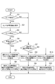
- the obstacle detection processing by this object detection device will be described with reference to the flowchart of FIG. This process is repeatedly executed by the obstacle detection ECU 1 at a predetermined timing during the obstacle detection operation.
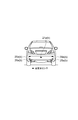
- the case where the ultrasonic sensors 21a and 21b are arranged at the same height (on the same horizontal plane) symmetrically to the vehicle center line as shown in FIG. 3 is described as an example.
- An orthogonal coordinate system is used in which the vehicle longitudinal direction is the x-axis, the horizontal direction is the y-axis, and the height direction is the z-axis.
- the obstacle detection unit 11 reads the detection results of the ultrasonic sensors 21a and 21b and calculates distance information (step S1).
- This distance information is obtained from the distance between the ultrasonic sensors 21a and 21b, the distance from each sensor 21a and 21b to the obstacle obtained from the detection result, and the positional relationship between the sensors 21a and 21b. Can be requested.
- the distance measured by the ultrasonic sensors 21a and 21b is specifically the shortest distance from each sensor 21a (21b) to the portion closest to the sensor 21a (21b) on the surface of the obstacle. Distance.
- the following process is not performed, and a loop process for performing the process of step S1 is performed until the obstacle is detected.
- the process proceeds to step S2 and the distance information is stored in the detection information storage unit 13.
- step S3 the obstacle detection unit 11 reads the detection results of the ultrasonic sensors 21a and 21b again and calculates the distance.
- This second distance detection may be performed after traveling a predetermined distance or more from the distance detection in step S1. This determination is performed by the vehicle position detection unit 12 calculating the travel distance from the output of the wheel speed sensor 22. Instead of the travel distance, the second distance detection condition may be a case where traveling at a predetermined speed or more continues for a predetermined time or more. If the second distance detection cannot be performed, the process returns to step S1 and starts again from the first distance detection. If the second distance detection is successful, the process proceeds to step S4. As described above, the distance detection twice is performed at each of the time when the movement is started and the time when the movement is completed, and includes any two time points during the movement. In the present invention, “before and after movement” represents before and after movement for an arbitrary period during movement.
- step S4 the trajectory of the vehicle is determined from the first distance detection (step S1) to the second distance detection (step S3). This trajectory determination can be made based on whether or not the steering angle neutral state has been continued from the output of the steering angle sensor 23 during traveling by the vehicle position detection unit 12. If the trajectory determination result is a straight trajectory, the process proceeds to step S5, where the obstacle position calculation unit 14 calculates the lateral distance Y from the current sensor distance information and the distance between the sensors.
- the lateral distance Y to the obstacle 200 can be obtained by trilateral survey.
- the obstacle position calculation unit 14 outputs the first distance information stored in the detection information storage unit 13 and the current second distance information, and the vehicle position detection unit 12 outputs the wheel speed sensor 22.
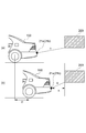
- the horizontal distance X to the obstacle at the time of step S3 and the height position Z are calculated (see FIG. 4).
- the distance to the obstacle 200 on the ZX plane obtained by the first distance information is A
- the distance to the obstacle 200 on the ZX plane obtained by the second distance information is B.
- a and B can be calculated on the basis of the triangulation principle in the same manner as Y described above. The relationship between A, B, D, X, and Z is illustrated in FIG.
- D, X, and Z can also be calculated based on the triangulation principle.
- the distance information thus obtained is stored in the detection information storage unit 13. 4 and 5 show the case of the backward movement approaching the obstacle, the same applies to the case of the forward movement away from the obstacle.
- the obstacle position calculation unit 14 may store the positional relationship between the obstacle and the vehicle as a relative position with respect to the vehicle, but may store the positional relationship using absolute coordinates in a coordinate system in which a reference point is placed outside the vehicle. Good.
- the distance information that the vehicle has traveled before and after the movement may be grasped as a movement amount (vector amount) for each axial component in the space coordinates or the plane coordinates, or as a scalar amount.
- step S4 If it is determined in step S4 that the vehicle track is not in a straight traveling state, that is, that the vehicle is being steered, the process proceeds to step S7, where the past height information Z is stored in the detection information storage unit 13. Determine whether or not.
- step S8 the process proceeds to step S8, and the lateral distance Y is calculated from the current sensor distance information B and the distance between the sensors by the same processing as in step S5. Subsequently, the obstacle position calculation unit 14 calculates the horizontal distance X from the current distance information B and height information Z to the obstacle based on the trilateral survey principle (step S9).
- step S10 the process proceeds to step S10, and the lateral distance Y is calculated from the current sensor distance information B and the distance between the sensors by the same process as step S5. To do. Subsequently, the obstacle position calculation unit 14 calculates the horizontal distance X to the obstacle assuming that the current distance information B and the height information Z are 0 (step S11). X at this time is assumed to be equal to B.
- the driver can easily determine the possibility of contact with the obstacle.
- automatically determining the possibility of contact with the obstacle based on the spatial position of the obstacle, and when issuing an obstacle approach warning to the occupant it is possible to suppress unnecessary warnings, Improves system reliability. Furthermore, you may use for the collision avoidance control with an obstruction.
- the current positional relationship with the obstacle may be saved by the same method as the process of step S9.
- the movement of the vehicle in this case is not limited to turning, and the present invention can also be applied to a case where the vehicle is moving with any movement locus of linear movement, turning movement, or movement combining these.
- the height information Z obtained by this method cannot be distinguished until the obstacle is above or below the sensor position. Therefore, as shown in FIG. 6, if two sets of ultrasonic sensors 25 and 26 are arranged at different height positions, obstacles that exist below the curb etc. based on the difference in height information. Can be distinguished from obstacles existing above. Furthermore, a plurality of sets of ultrasonic sensors 21, 25, 26, 28, and 29 may be arranged as shown in FIG.
- the present invention can also be applied when the object is a moving object such as a pedestrian (see FIG. 8).
- the object is a moving object such as a pedestrian (see FIG. 8).
- the relative speed of the moving object is calculated, and if necessary, the height and speed are corrected by multiple measurements. Good.
- the position of the obstacle based on the positional relationship information at the position where the distance information can be acquired and the subsequent trajectory of the vehicle even for the position of the stationary object close to the vehicle where it is difficult to acquire the distance information with the ultrasonic sensor. Track relationship changes and determine the current obstacle location.
- the present invention is suitable as an obstacle sensor mounted on a vehicle.
Landscapes
- Engineering & Computer Science (AREA)
- Radar, Positioning & Navigation (AREA)
- Remote Sensing (AREA)
- Physics & Mathematics (AREA)
- Acoustics & Sound (AREA)
- Computer Networks & Wireless Communication (AREA)
- General Physics & Mathematics (AREA)
- Measurement Of Velocity Or Position Using Acoustic Or Ultrasonic Waves (AREA)
- Traffic Control Systems (AREA)
Abstract
障害物の空間位置を精度よく判定することを可能とした車両用物体検出装置を提供する。距離測定部として例えば少なくとも2個の超音波センサ21a、21bを配置し、車両の直進移動前後に測定した物体との距離と、車両の移動距離を検出する移動距離取得部(車輪速センサ22)により測定したこの直進移動時の移動距離に基づいて、各距離の幾何学的関係から検出した障害物の空間位置を算出する。
Description
本発明は、車両に搭載されて、車両周囲の障害物を検出する車両用物体検出装置および方法に関する。
車両に超音波ソナーやレーザレーダ等を搭載し、車両周囲の障害物を検出する技術が知られている。特許文献1に開示されている技術はこうした障害物検出技術の一例であって、センサで検出した障害物までの距離を勘案して車両乗員に対する警報度を設定するものである。
超音波ソナーやレーザレーダ等は、センサと障害物の反射表面とを結んだ最短直線距離を検出するものである。センサと障害物とが同一水平面内に位置していれば、最短直線距離=水平距離であるが、センサと障害物とが同一水平面内に位置していない場合(両者に高さの差がある場合)には、検出した最短直線距離は、本来の水平方向の距離より長いため、障害物が実際より遠くにあると判定してしまう。
そこで本発明は、障害物の空間位置を精度よく判定することを可能とした車両用物体検出装置、方法を提供することを課題とする。
上記課題を解決するため、本発明に係る車両用物体検出装置は、障害物までの距離を測定する少なくとも二個の距離測定部と、車両の移動距離を取得する移動距離取得部と、車両の直進移動前後それぞれにおいて各距離測定部により測定された障害物までの距離と、移動距離取得部により取得したこの移動間の移動距離と、距離測定部間の距離と、に基づいて障害物と車両との位置関係を算出する位置算出部と、を備えていることを特徴とする。
一方、本発明に係る車両用物体検出方法は、車両の直進移動前後それぞれにおいて、車両上の2点から障害物までの距離をそれぞれ測定し、この直進移動時の車両の移動距離をあわせて取得し、測定した車両の直進移動前後それぞれにおける車両上の2点から障害物までの距離と、取得した当該直進移動時の車両の移動距離と、当該車両上の2点の距離と、に基づいて障害物と車両との位置関係を算出する、各工程を備えていることを特徴とする
位置算出部は、算出された位置関係を保存し、保存された過去の位置関係と、移動距離取得部により取得した車両の移動距離と、に基づいて車両と障害物との位置関係を算出するものでもよい。あるいは、位置算出部が算出する障害物と車両との位置関係には、高さ情報を含んでおり、位置算出部は、算出された位置関係における高さ情報を保存し、こうして保存された過去の位置関係における高さ情報と各距離測定部によって測定された障害物までの距離と、に基づいて車両と障害物との位置関係を算出してもよい。
2つの距離測定部の距離情報とその位置関係から、三角測量原理によって両距離測定部位置を含む任意の平面内における物体の空間位置が求まる。この平面自体は限定されていないので、可能な物体の空間位置としては、距離測定部の中間点を中心とする所定の半径の円弧上に位置しうる。車両移動前後の2カ所で求めた距離情報をもとにすることで、中心を異にする二つの円弧の交点として障害物の空間位置を求めることができる。この結果、障害物の空間位置を精度よく把握することが可能となる。
算出した位置関係を保存して、保存結果を利用して障害物の位置を算出することで、障害物の追跡等を精度よく行うことが可能となる。
以下、添付図面を参照して本発明の好適な実施の形態について詳細に説明する。説明の理解を容易にするため、各図面において同一の構成要素に対しては可能な限り同一の参照番号を附し、重複する説明は省略する。
図1に本発明に係る車両用物体検出装置の第1の実施形態の構成を示す。この物体検出装置は、制御部である障害物検出ECU(Electric Control Unit)1を中心に構成される。障害物検出ECU1は、RAM、ROM、CPU等によって構成されており、内部に、障害物検出部11、車両位置検出部12、検出情報記憶部13、障害物位置算出部14を備えている。障害物検出ECU1内の各部は、ハードウェア的に区分されていてもよいが、ハードウェアの一部または全部を共用するソフトウェアとして構成されていてもよく、その場合、各部を構成するソフトウェアは一部を共用してもよく、同一ソフトウェア中で複数の機能が実現されていてもよい。障害物検出ECU1には、対物センサである2個の超音波センサ21a、21bと、車輪の回転速度を検出する車輪速センサ22、操舵角を検出する舵角センサ23の出力が入力されている。
超音波センサ21a、21bは、距離測定部として機能するものであり、超音波を照射し、物体表面で反射した反射波を受信して、照射から、反射波受信までの時間に基づいて物体との距離を算出するものである。車輪速センサ22は、移動距離取得部のセンサとして機能するものであり、例えば、車輪の回転に同期して1回転に所定個数のパルス信号を発するタイプのセンサを用いることができる。車輪速センサ22は、車輪の回転速度、走行距離、車速の検出に用いることができる。舵角センサ23は、ステアリング系に配置され、舵角を検出するものである。
この物体検出装置による障害物検出処理を図2のフローチャートを参照して説明する。この処理は、障害物検出ECU1により、障害物検出動作中に所定のタイミングで繰り返し実行される。ここでは、超音波センサ21a、21bを図3に示されるように車両後部中央に、車両中心線に対称に同一高さ(同一水平面上)に配置している場合を例に説明する。車両前後方向をx軸、左右方向をy軸、高さ方向をz軸とする直交座標系を用いる。
最初に障害物検出部11は、超音波センサ21a、21bの検出結果を読み込み、距離情報を算出する(ステップS1)。この距離情報は、超音波センサ21a、21b間の距離、検出結果から得られた各センサ21a、21bから障害物までの距離と、センサ21a、21bの位置関係から三辺測量原理により幾何学的に求めることができる。なお、超音波センサ21a、21bによって測定される距離は、具体的には、それぞれのセンサ21a(21b)から、障害物の表面上の最も当該センサ21a(21b)に近い部分までを結んだ最短距離である。障害物を検出していない場合には、以降の処理に入らず、障害物を検出するまでステップS1の処理を行うループ処理を行う。障害物を検出した場合には、ステップS2へと移行してこの距離情報を検出情報記憶部13に保存する。
ステップS3では、障害物検出部11は、再度、超音波センサ21a、21bの検出結果を読み込み、距離を算出する。この2度目の距離検出は、ステップS1の距離検出から所定走行距離以上走行後に行うようにするとよい。この判定は、車両位置検出部12が、車輪速センサ22の出力から走行距離を算出することにより行う。走行距離にかえて、所定速度以上の走行が所定時間以上継続している場合を2度目の距離検出条件としてもよい。2度目の距離検出が行えない場合には、ステップS1に戻り、1度目の距離検出からやり直す。2度目の距離検出が成功した場合には、ステップS4へと移行する。このように2度の距離検出は、移動を始めた時点と終了した時点のそれぞれで行う場合のほか、移動中における任意の2つの時点のいずれをも含むものである。本発明における「移動前後」とは、移動中の任意の期間についての移動の前後を表している。
ステップS4では、1度目の距離検出(ステップS1)から2度目の距離検出(ステップS3)での車両の軌道を判定する。この軌道判定は、車両位置検出部12により走行中の舵角センサ23の出力から舵角中立状態が継続していたか否かにより判定することができる。軌道判定結果が直進軌道であった場合は、ステップS5に移行して、障害物位置算出部14が現在のセンサ距離情報とセンサ間の距離から横方向距離Yを算出する。
図3に示されるように、超音波センサ21a、21bそれぞれで検出した障害物200までの距離をそれぞれDR、DLとし、センサ間の距離をLとすると、超音波センサ21a、21bの中間点から障害物200までの横方向距離Yは、三辺測量によって求めることができる。
続くステップS6では、障害物位置算出部14は、検出情報記憶部13に保存されている1度目の距離情報と現在の2度目の距離情報と、車両位置検出部12が車輪速センサ22の出力に基づいて判定したステップS1~S3で走行した距離情報Dに基づいてステップS3の時点における障害物までの水平方向距離Xと、高さ位置Zを算出する(図4参照)。ここで、1度目の距離情報で得られるZX平面上の障害物200までの距離をA、2度目の距離情報で得られるZX平面上の障害物200までの距離をBとする。A、Bは、上述のYと同様に三辺測量原理に基づいて算出できる。A、B、D、X、Zの関係を図示すると、図5のようになるから、D、X、Zについてもそれぞれ三辺測量原理に基づいて算出できる。こうして求めた距離情報は、検出情報記憶部13内に保存される。図4、図5では障害物に対して接近する後退移動の場合を示しているが、障害物から遠ざかる前進移動の場合にも同様に適用できる。
障害物位置算出部14は、障害物と車両との位置関係を車両に対する相対位置として保存してもよいが、車両外に基準点を置く座標系中の絶対座標により位置関係を保存してもよい。
移動前後に車両が走行した距離情報は、空間座標または平面座標中の軸方向成分ごとの移動量(ベクトル量)として把握してもよいし、スカラー量として把握してもよい。
ステップS4では、車両の軌道が直進状態でない、つまり、操舵中であると判定した場合には、ステップS7へと移行して、検出情報記憶部13に過去の高さ情報Zが保存されているか否かを判定する。
高さ情報Zが保存されている場合には、ステップS8へと移行し、ステップS5と同様の処理により、現在のセンサ距離情報Bとセンサ間の距離から横方向距離Yを算出する。続いて、障害物位置算出部14が、現在の距離情報Bと高さ情報Zから障害物までの水平方向距離Xを三辺測量原理に基づいて算出する(ステップS9)。
一方、過去の高さ情報Zが保存されていない場合には、ステップS10へと移行し、ステップS5と同様の処理により、現在のセンサ距離情報Bとセンサ間の距離から横方向距離Yを算出する。続いて、障害物位置算出部14が現在の距離情報Bと高さ情報Zを0と仮定して障害物までの水平方向距離Xを算出する(ステップS11)。このときのXはBに等しいと仮定されることになる。
本実施形態によれば、障害物の空間位置を精度よく把握することができる。これに基づいて障害物の位置情報を提供すれば、運転者が障害物の接触可能性を容易に判定することができる。また、障害物の空間位置に基づいて障害物との接触可能性を自動的に判定して、乗員に対して障害物の接近警報を発する場合には、不要な警報を抑制することができ、システムに対する信頼性が向上する。さらに、障害物との衝突回避制御に用いてもよい。
すでに車両と障害物との過去の位置関係が保存されている場合には、ステップS9の処理と同様の手法により、現在の障害物との位置関係を保存してもよい。この場合の車両の移動は旋回時に限られるものではなく、直進移動、旋回移動、またはこれらを組み合わせた移動のいずれの移動軌跡をもって車両が移動している場合においても適用可能である。
なお、この手法によって得られる高さ情報Zは、障害物がセンサ位置より上方、下方のいずれにあるかまでは判別できない。そこで、図6に示されるように、高さ位置の異なる場所に2組の超音波センサ25、26を配置しておくと、高さ情報の違いに基づいて縁石等の下方に存在する障害物と上方に存在する障害物とを区別することができる。さらに、図7に示されるように複数組の超音波センサ21、25、26、28、29を配置してもよい。
ここでは、測定対象物が静止物の場合を例に説明してきたが、対象物が歩行者等の移動体である場合にも適用可能である(図8参照)。この場合は、例えば、静止物と同様の手法で求めた高さを移動体210の高さとみて移動体の相対速度を算出し、必要ならば複数回の測定で高さ、速度を修正すればよい。
さらに、超音波センサでは距離情報の取得が困難な車両に近接する静止物の位置についても距離情報の取得が可能な位置での位置関係情報とその後の車両の軌跡に基づいて障害物との位置関係変化を追跡し、現在の障害物位置を求めるとよい。
以上の説明では、距離測定部の対物センサとして超音波センサ(ソナー)を用いた場合を例に説明したが、赤外線センサやレーザレーダのようにその他の対象物に対して音、光、電波等を照射してその反射波を受信し、照射から受信までの時間に基づいて物体までの距離を測定する各種の対物センサを用いることができる。
本発明は、車両に搭載される障害物センサとして好適である。
1…障害物検出ECU、11…障害物検出部、12…車両位置検出部、13…検出情報記憶部、14…障害物位置算出部、21、25、26、28、29…超音波センサ、22…車輪速センサ、23…舵角センサ、200…障害物、210…移動体。
Claims (4)
- 障害物までの距離を測定する少なくとも二個の距離測定部と、
車両の移動距離を取得する移動距離取得部と、
前記車両の直進移動前後それぞれにおいて各距離測定部により測定された前記障害物までの距離と、前記移動距離取得部により取得した前記移動間の移動距離と、前記距離測定部間の距離と、に基づいて前記障害物と前記車両との位置関係を算出する位置算出部と、
を備えていることを特徴とする車両用物体検出装置。 - 前記位置算出部は、算出された位置関係を保存し、該保存された過去の位置関係と、前記移動距離取得部により取得した車両の移動距離と、に基づいて前記車両と前記障害物との位置関係を算出することを特徴とする請求項1記載の車両用物体検出装置。
- 前記位置算出部が算出する前記障害物と前記車両との位置関係には、高さ情報を含んでおり、
前記位置算出部は、算出された位置関係における高さ情報を保存し、該保存された過去の位置関係における高さ情報と各距離測定部によって測定された前記障害物までの距離と、に基づいて前記車両と前記障害物との位置関係を算出することを特徴とする請求項1または2のいずれかに記載の車両用物体検出装置。 - 車両の直進移動前後それぞれにおいて、車両上の2点から障害物までの距離をそれぞれ測定し、
当該直進移動時の車両の移動距離をあわせて取得し、
測定した車両の直進移動前後それぞれにおける車両上の2点から障害物までの距離と、取得した当該直進移動時の車両の移動距離と、当該車両上の2点の距離と、に基づいて前記障害物と前記車両との位置関係を算出する、
各工程を備えていることを特徴とする車両用物体検出方法。
Priority Applications (1)
| Application Number | Priority Date | Filing Date | Title |
|---|---|---|---|
| PCT/JP2011/059295 WO2012140769A1 (ja) | 2011-04-14 | 2011-04-14 | 車両用物体検出装置および方法 |
Applications Claiming Priority (1)
| Application Number | Priority Date | Filing Date | Title |
|---|---|---|---|
| PCT/JP2011/059295 WO2012140769A1 (ja) | 2011-04-14 | 2011-04-14 | 車両用物体検出装置および方法 |
Publications (1)
| Publication Number | Publication Date |
|---|---|
| WO2012140769A1 true WO2012140769A1 (ja) | 2012-10-18 |
Family
ID=47008971
Family Applications (1)
| Application Number | Title | Priority Date | Filing Date |
|---|---|---|---|
| PCT/JP2011/059295 Ceased WO2012140769A1 (ja) | 2011-04-14 | 2011-04-14 | 車両用物体検出装置および方法 |
Country Status (1)
| Country | Link |
|---|---|
| WO (1) | WO2012140769A1 (ja) |
Cited By (10)
| Publication number | Priority date | Publication date | Assignee | Title |
|---|---|---|---|---|
| JP2014215283A (ja) * | 2013-04-30 | 2014-11-17 | 株式会社デンソー | 障害物検出装置 |
| CN105008955A (zh) * | 2013-03-04 | 2015-10-28 | 松下知识产权经营株式会社 | 车辆障碍物检测设备和车辆障碍物检测系统 |
| WO2017191201A1 (de) * | 2016-05-06 | 2017-11-09 | Audi Ag | Kraftfahrzeug mit wenigstens zwei radarsensoren |
| GB2564232A (en) * | 2017-05-18 | 2019-01-09 | Jaguar Land Rover Ltd | A system for use in a vehicle |
| CN109910009A (zh) * | 2019-03-13 | 2019-06-21 | 浙江华消科技有限公司 | 消防侦察机器人的路径生成方法、装置、系统和机器人 |
| CN115356733A (zh) * | 2022-07-26 | 2022-11-18 | 润光智能(深圳)有限公司 | 基于多雷达的障碍物定位方法、装置、设备及存储介质 |
| US11536073B2 (en) | 2019-02-14 | 2022-12-27 | Brose Fahrzeugteile Se & Co. Kommanditgesellschaft, Bamberg | Adjustment assembly for a vehicle with an ultrasonic system and method for obstacle detection |
| WO2023282098A1 (ja) * | 2021-07-09 | 2023-01-12 | 株式会社アイシン | 物体検出装置及び物体検出方法 |
| DE102021208072A1 (de) | 2021-07-27 | 2023-02-02 | Continental Autonomous Mobility Germany GmbH | Verfahren zur Höhenschätzung von Objekten mittels Ultraschallsensorik |
| US12618956B2 (en) | 2021-07-09 | 2026-05-05 | Aisin Corporation | Object detection device and object detection method |
Citations (2)
| Publication number | Priority date | Publication date | Assignee | Title |
|---|---|---|---|---|
| JP2007140852A (ja) * | 2005-11-17 | 2007-06-07 | Aisin Seiki Co Ltd | 障害物位置検出装置及び障害物位置検出方法 |
| WO2007111130A1 (ja) * | 2006-03-27 | 2007-10-04 | Murata Manufacturing Co., Ltd. | レーダ装置および移動体 |
-
2011
- 2011-04-14 WO PCT/JP2011/059295 patent/WO2012140769A1/ja not_active Ceased
Patent Citations (2)
| Publication number | Priority date | Publication date | Assignee | Title |
|---|---|---|---|---|
| JP2007140852A (ja) * | 2005-11-17 | 2007-06-07 | Aisin Seiki Co Ltd | 障害物位置検出装置及び障害物位置検出方法 |
| WO2007111130A1 (ja) * | 2006-03-27 | 2007-10-04 | Murata Manufacturing Co., Ltd. | レーダ装置および移動体 |
Cited By (17)
| Publication number | Priority date | Publication date | Assignee | Title |
|---|---|---|---|---|
| CN105008955A (zh) * | 2013-03-04 | 2015-10-28 | 松下知识产权经营株式会社 | 车辆障碍物检测设备和车辆障碍物检测系统 |
| EP2966472A4 (en) * | 2013-03-04 | 2016-04-20 | Panasonic Ip Man Co Ltd | VEHICLE DETECTION DEVICE AND VEHICLE DISABLING DETECTION DEVICE |
| US9507023B2 (en) | 2013-03-04 | 2016-11-29 | Panasonic Intellectual Property Management Co., Ltd. | Obstacle detection device for vehicle and obstacle detection system for vehicle |
| CN105008955B (zh) * | 2013-03-04 | 2017-02-22 | 松下知识产权经营株式会社 | 车辆障碍物检测设备和车辆障碍物检测系统 |
| JP2014215283A (ja) * | 2013-04-30 | 2014-11-17 | 株式会社デンソー | 障害物検出装置 |
| WO2017191201A1 (de) * | 2016-05-06 | 2017-11-09 | Audi Ag | Kraftfahrzeug mit wenigstens zwei radarsensoren |
| GB2564232A (en) * | 2017-05-18 | 2019-01-09 | Jaguar Land Rover Ltd | A system for use in a vehicle |
| US11536073B2 (en) | 2019-02-14 | 2022-12-27 | Brose Fahrzeugteile Se & Co. Kommanditgesellschaft, Bamberg | Adjustment assembly for a vehicle with an ultrasonic system and method for obstacle detection |
| CN109910009A (zh) * | 2019-03-13 | 2019-06-21 | 浙江华消科技有限公司 | 消防侦察机器人的路径生成方法、装置、系统和机器人 |
| US12618956B2 (en) | 2021-07-09 | 2026-05-05 | Aisin Corporation | Object detection device and object detection method |
| WO2023282098A1 (ja) * | 2021-07-09 | 2023-01-12 | 株式会社アイシン | 物体検出装置及び物体検出方法 |
| JP2023010177A (ja) * | 2021-07-09 | 2023-01-20 | 株式会社アイシン | 物体検出装置、物体検出方法、及びプログラム |
| EP4369040A4 (en) * | 2021-07-09 | 2024-11-27 | Aisin Corporation | OBJECT DETECTION DEVICE AND OBJECT DETECTION METHOD |
| CN117546048A (zh) * | 2021-07-09 | 2024-02-09 | 株式会社爱信 | 物体检测装置以及物体检测方法 |
| JP7563317B2 (ja) | 2021-07-09 | 2024-10-08 | 株式会社アイシン | 物体検出装置、物体検出方法、及びプログラム |
| DE102021208072A1 (de) | 2021-07-27 | 2023-02-02 | Continental Autonomous Mobility Germany GmbH | Verfahren zur Höhenschätzung von Objekten mittels Ultraschallsensorik |
| CN115356733A (zh) * | 2022-07-26 | 2022-11-18 | 润光智能(深圳)有限公司 | 基于多雷达的障碍物定位方法、装置、设备及存储介质 |
Similar Documents
| Publication | Publication Date | Title |
|---|---|---|
| WO2012140769A1 (ja) | 車両用物体検出装置および方法 | |
| US9880558B2 (en) | Travel control device | |
| CN105539437B (zh) | 对象检测装置 | |
| JP6269566B2 (ja) | 誤認識判定装置 | |
| JP6404679B2 (ja) | 物体検知装置 | |
| US10451722B2 (en) | In-vehicle object determining apparatus | |
| US20160114795A1 (en) | Parking assist system and parking assist method | |
| JP6747179B2 (ja) | 駐車支援方法及び駐車支援装置 | |
| US20150138011A1 (en) | Parking assisting device | |
| CA3008378A1 (en) | Parking support method and device | |
| JP5843948B1 (ja) | 駐車支援装置および駐車支援方法 | |
| JP4406608B2 (ja) | 車両の駐車過程用の幾何学的形状データを検出するための方法 | |
| JP2008195293A (ja) | 衝突予測装置 | |
| JP2014054912A (ja) | 駐車支援システム | |
| WO2019058578A1 (ja) | 測位支援装置 | |
| CN112771591A (zh) | 用于评价运输工具的环境中的对象对运输工具的行驶机动动作的影响的方法 | |
| KR20140104611A (ko) | 차량의 자동 주차 장치 및 이를 이용한 방법 | |
| WO2019203160A1 (ja) | 運転支援システムおよび方法 | |
| JP5861605B2 (ja) | 駐車支援システム及び位置決め体付き輪止め | |
| JP2009286355A (ja) | 駐車支援装置、駐車支援方法及びコンピュータプログラム | |
| JP2012113431A (ja) | 車両の前方障害物検出装置 | |
| JP6020021B2 (ja) | 駐車支援装置 | |
| JP2024100141A (ja) | 自律走行車両 | |
| JP2013016052A (ja) | 車両用物体認識装置 | |
| JP2011220860A (ja) | 障害物検出装置 |
Legal Events
| Date | Code | Title | Description |
|---|---|---|---|
| 121 | Ep: the epo has been informed by wipo that ep was designated in this application |
Ref document number: 11863587 Country of ref document: EP Kind code of ref document: A1 |
|
| NENP | Non-entry into the national phase |
Ref country code: DE |
|
| NENP | Non-entry into the national phase |
Ref country code: JP |
|
| 122 | Ep: pct application non-entry in european phase |
Ref document number: 11863587 Country of ref document: EP Kind code of ref document: A1 |