WO2012137866A1 - 露光方法、露光装置、及びデバイス製造方法 - Google Patents
露光方法、露光装置、及びデバイス製造方法 Download PDFInfo
- Publication number
- WO2012137866A1 WO2012137866A1 PCT/JP2012/059354 JP2012059354W WO2012137866A1 WO 2012137866 A1 WO2012137866 A1 WO 2012137866A1 JP 2012059354 W JP2012059354 W JP 2012059354W WO 2012137866 A1 WO2012137866 A1 WO 2012137866A1
- Authority
- WO
- WIPO (PCT)
- Prior art keywords
- substrate
- deformation
- exposure
- pattern
- alignment marks
- Prior art date
- Legal status (The legal status is an assumption and is not a legal conclusion. Google has not performed a legal analysis and makes no representation as to the accuracy of the status listed.)
- Ceased
Links
Images





Classifications
-
- G—PHYSICS
- G03—PHOTOGRAPHY; CINEMATOGRAPHY; ANALOGOUS TECHNIQUES USING WAVES OTHER THAN OPTICAL WAVES; ELECTROGRAPHY; HOLOGRAPHY
- G03F—PHOTOMECHANICAL PRODUCTION OF TEXTURED OR PATTERNED SURFACES, e.g. FOR PRINTING, FOR PROCESSING OF SEMICONDUCTOR DEVICES; MATERIALS THEREFOR; ORIGINALS THEREFOR; APPARATUS SPECIALLY ADAPTED THEREFOR
- G03F7/00—Photomechanical, e.g. photolithographic, production of textured or patterned surfaces, e.g. printing surfaces; Materials therefor, e.g. comprising photoresists; Apparatus specially adapted therefor
- G03F7/70—Microphotolithographic exposure; Apparatus therefor
- G03F7/70691—Handling of masks or workpieces
- G03F7/70783—Handling stress or warp of chucks, masks or workpieces, e.g. to compensate for imaging errors or considerations related to warpage of masks or workpieces due to their own weight
Definitions
- the present invention relates to an exposure method, an exposure apparatus, and a device manufacturing method.
- This application claims priority based on Japanese Patent Application No. 2011-083594 filed on Apr. 5, 2011, the contents of which are incorporated herein by reference.
- an exposure apparatus that exposes a substrate with exposure light as disclosed in Patent Document 1 is used.
- the device is formed by stacking a plurality of patterns (patterned films) on a substrate.
- the alignment mark of the substrate is measured, and based on the measurement result of the alignment mark, the substrate and the image of the next pattern are measured.
- An alignment process for performing alignment is executed.
- the pattern overlay accuracy is lowered, and as a result, an exposure failure and a defective device occur. Even when the substrate is deformed, it is effective to accurately acquire information related to the deformation of the substrate in order to suppress a decrease in the overlay accuracy of the pattern.
- the deformation of the substrate includes a non-linear component (non-linear distortion)
- information regarding the deformation of the substrate including the non-linear distortion can be accurately acquired by increasing the number of measurement points of the alignment mark.
- the number of measurement points of the alignment mark is increased, it takes time for the measurement, and the throughput may be reduced.
- An object of the present invention is to provide an exposure method and an exposure apparatus that can accurately acquire information related to substrate deformation and suppress the occurrence of exposure failure while suppressing a decrease in throughput. Moreover, the aspect which concerns on this invention aims at providing the device manufacturing method which can suppress generation
- One aspect according to the present invention is an exposure method for exposing a substrate with exposure light, wherein information relating to the deformation of the first portion of the outer edge region including the edge of the substrate is acquired, and the acquired result has a predetermined relationship. Obtaining information on the deformation of the second part of the outer edge region different from the first part based on the formula, and exposing the substrate based on the obtained information on the deformation of the first part and the second part. , including.
- the device manufacturing method includes exposing a substrate using the exposure method according to the above aspect and developing the exposed substrate.
- An aspect of the present invention is an exposure apparatus that exposes a substrate with exposure light, and includes a first acquisition apparatus that acquires information related to deformation of a first portion of an outer edge region including an edge of the substrate, and a first acquisition apparatus.
- a second acquisition device that acquires information related to deformation of the second part of the outer edge region different from the first part based on the acquired result and a predetermined relational expression, and the acquired first part and second part The substrate is exposed based on the information on the deformation.
- a device manufacturing method includes exposing a substrate using the exposure apparatus and developing the exposed substrate.
- the aspect of the present invention it is possible to suppress the occurrence of exposure failure while suppressing a decrease in throughput. Moreover, according to the aspect which concerns on this invention, generation
- an XYZ orthogonal coordinate system is set, and the positional relationship of each part will be described with reference to this XYZ orthogonal coordinate system.
- a predetermined direction in the horizontal plane is defined as an X-axis direction
- a direction orthogonal to the X-axis direction in the horizontal plane is defined as a Y-axis direction
- a direction orthogonal to each of the X-axis direction and the Y-axis direction (that is, a vertical direction) is defined as a Z-axis direction.
- the rotation (inclination) directions around the X axis, Y axis, and Z axis are the ⁇ X, ⁇ Y, and ⁇ Z directions, respectively.
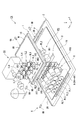
- FIG. 1 is a schematic block diagram showing an example of an exposure apparatus EX according to the first embodiment
- FIG. 2 is a perspective view. 1 and 2
- an exposure apparatus EX includes a mask stage 1 that can move while holding a mask M, a substrate stage 2 that can move while holding a substrate P, and a drive system 3 that moves the mask stage 1.
- a driving system 4 that moves the substrate stage 2, an illumination system IS that illuminates the mask M with the exposure light EL, a projection system PS that projects an image of the pattern of the mask M illuminated by the exposure light EL onto the substrate P, A control device 5 that controls the operation of the entire exposure apparatus EX, and a storage device 5R that is connected to the control device 5 and stores various types of information related to exposure are provided.
- the mask M includes a reticle on which a device pattern projected onto the substrate P is formed.
- the substrate P includes, for example, a base material such as a glass plate and a photosensitive film (coated photosensitizer) formed on the base material.
- the outer shape of the substrate P is a rectangle.
- the substrate P includes a large glass plate, and the size of one side of the substrate P is, for example, 500 mm or more.
- a square glass plate having a side of about 3000 mm is used as the base material of the substrate P.
- the exposure apparatus EX of the present embodiment also includes an interferometer system 6 that measures position information of the mask stage 1 and the substrate stage 2, and a first detection that detects position information of the surface (lower surface, pattern formation surface) of the mask M.
- the system 7 includes a second detection system 8 that detects position information on the surface (exposure surface, photosensitive surface) of the substrate P, and an alignment system 9 that performs alignment mark measurement on the substrate P.
- the exposure apparatus EX includes a body 13.
- the body 13 includes, for example, a base plate 10 disposed on a support surface (for example, floor surface) FL in a clean room via a vibration isolation table BL, a first column 11 disposed on the base plate 10, and a first column 11 And a second column 12 disposed on the surface.
- the body 13 supports each of the projection system PS, the mask stage 1 and the substrate stage 2.
- the projection system PS is supported by the first column 11 via the surface plate 14.
- the mask stage 1 is supported so as to be movable with respect to the second column 12.
- the substrate stage 2 is supported so as to be movable with respect to the base plate 10.
- the projection system PS has a plurality of projection optical systems.
- the illumination system IS has a plurality of illumination modules corresponding to a plurality of projection optical systems.
- the exposure apparatus EX of the present embodiment projects an image of the pattern of the mask M onto the substrate P while moving the mask M and the substrate P synchronously in a predetermined scanning direction. That is, the exposure apparatus EX of the present embodiment is a so-called multi-lens scan exposure apparatus.
- the projection system PS has seven projection optical systems PL1 to PL7, and the illumination system IS has seven illumination modules IL1 to IL7.
- the number of projection optical systems and illumination modules is not limited to seven.
- the projection system PS may have 11 projection optical systems, and the illumination system IS may have 11 illumination modules.
- the illumination system IS can irradiate the predetermined illumination areas IR1 to IR7 with the exposure light EL.
- the illumination areas IR1 to IR7 are included in the irradiation areas of the exposure light EL emitted from the illumination modules IL1 to IL7.
- the illumination system IS illuminates each of the seven different illumination areas IR1 to IR7 with the exposure light EL.
- the illumination system IS illuminates portions of the mask M arranged in the illumination regions IR1 to IR7 with exposure light EL having a uniform illuminance distribution.
- bright lines g line, h line, i line
- a mercury lamp are used as the exposure light EL emitted from the illumination system IS.
- the mask stage 1 is movable with respect to the illumination regions IR1 to IR7 while holding the mask M.
- the mask stage 1 includes a mask holding unit 15 that can hold the mask M.
- the mask holding unit 15 includes a chuck mechanism that can vacuum-suck the mask M, and holds the mask M in a releasable manner. In the present embodiment, the mask holding unit 15 holds the mask M so that the lower surface (pattern forming surface) of the mask M and the XY plane are substantially parallel.
- the drive system 3 includes, for example, a linear motor, and can move the mask stage 1 on the guide surface 12G of the second column 12.
- the mask stage 1 is moved in the three directions of the X axis, the Y axis, and the ⁇ Z direction on the guide surface 12G in a state where the mask M is held by the mask holding unit 15 by the operation of the drive system 3. It is movable.
- the projection system PS can irradiate the predetermined projection areas PR1 to PR7 with the exposure light EL.
- the projection areas PR1 to PR7 correspond to the irradiation areas of the exposure light EL emitted from the projection optical systems PL1 to PL7.
- the projection system PS projects a pattern image on each of seven different projection regions PR1 to PR7.
- the projection optical system PS projects an image of the pattern of the mask M on the portion of the substrate P arranged in the projection areas PR1 to PR7 with a predetermined projection magnification.
- the substrate stage 2 is movable with respect to the projection regions PR1 to PR7 while holding the substrate P.
- the substrate stage 2 includes a substrate holding unit 16 that can hold the substrate P.
- the substrate holding unit 16 includes a chuck mechanism capable of vacuum-sucking the substrate P, and holds the substrate P so that the substrate P can be released.
- the substrate holding unit 16 holds the substrate P so that the surface (exposure surface) of the substrate P and the XY plane are substantially parallel.
- the drive system 4 includes, for example, a linear motor, and can move the substrate stage 2 on the guide surface 10 ⁇ / b> G of the base plate 10.
- the substrate stage 2 operates on the guide surface 10G with the X-axis, Y-axis, Z-axis, ⁇ X, ⁇ Y, and It can move in six directions of ⁇ Z direction.
- the interferometer system 6 includes a laser interferometer unit 6A that measures position information of the mask stage 1 and a laser interferometer unit 6B that measures position information of the substrate stage 2.
- the laser interferometer unit 6 ⁇ / b> A can measure position information of the mask stage 1 using a measurement mirror 1 ⁇ / b> R disposed on the mask stage 1.
- the laser interferometer unit 6 ⁇ / b> B can measure the position information of the substrate stage 2 using the measurement mirror 2 ⁇ / b> R disposed on the substrate stage 2.
- the interferometer system 6 can measure position information of the mask stage 1 and the substrate stage 2 with respect to the X axis, Y axis, and ⁇ X directions using the laser interferometer units 6A and 6B.
- control device 5 When executing the exposure process of the substrate P or when executing a predetermined measurement process, the control device 5 operates the drive systems 3 and 4 based on the measurement result of the interferometer system 6 to thereby operate the mask stage 1 (mask M) and position control of the substrate stage 2 (substrate P).
- the alignment system 9 measures alignment marks provided on the substrate P.
- the alignment system 9 is a so-called off-axis alignment system, and includes a plurality of microscopes 9A to 9F arranged to face the surface of the substrate P held on the substrate stage 2.
- Each of the microscopes 9A to 9F includes a projection unit that irradiates detection light to the detection regions AL1 to AL6, and a light receiving unit that can acquire an optical image of the alignment marks arranged in the detection regions AL1 to AL6.
- the control device 5 performs an exposure process so that the pattern image of the mask M formed by the projection system PS is superimposed on the pattern already formed on the substrate P. During the exposure process, the control device 5 measures the alignment mark of the substrate P, and executes an alignment process for aligning the substrate P and the pattern image of the mask M based on the measurement result of the alignment mark.
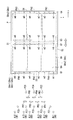
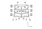
- FIG. 3 is a schematic diagram showing an example of the positional relationship between the projection areas PR1 to PR7 of the projection system PS, the detection areas AL1 to AL6 of the alignment system 9, and the substrate P. In the plane including the surface of the substrate P, FIG. The positional relationship is shown.
- the outer shape of the substrate P is a quadrangle.
- the outer shape of the substrate P is a rectangle that is long in the X-axis direction.
- the external shape of the substrate P may be a square or a rectangle that is long in the Y-axis direction.
- the substrate P has four sides.
- the substrate P has two sides S1 and S2 that are substantially parallel to the X-axis direction, and two sides S3 and S4 that are substantially parallel to the Y-axis direction.
- first side S1 is a + Y side side
- second side S2 is a ⁇ Y side side
- the third side S3 is a ⁇ X side side
- the fourth side S4 is a + X side side.
- the outer edge region of the substrate P including the end (side) of the substrate P is appropriately referred to as an outer edge region GA.
- substrates P is suitably called inner area
- the internal area UA is an area including the center of the substrate P.
- the outer edge area GA is an area arranged around the inner area UA.
- a portion long (extending) in the Y-axis direction is appropriately referred to as a Y portion GAy
- a portion extending in the X-axis direction is appropriately referred to as an X portion GAx.
- the Y portion GAy includes a first Y portion GAy1 including a third side S3 extending in the Y-axis direction and a second Y portion GAy2 including a fourth side S4 extending in the Y-axis direction.
- the X portion GAx includes a first X portion GAx1 including a first side S1 extending in the X-axis direction and a second X portion GAx2 including a second side S2 extending in the X-axis direction.
- the first Y portion GAy1 is disposed on the ⁇ X side with respect to the center of the substrate P
- the second Y portion GAy2 is disposed on the + X side with respect to the center of the substrate P.
- the first X portion GAx1 is disposed on the + Y side with respect to the center of the substrate P
- the second X portion GAx2 is disposed on the ⁇ Y side with respect to the center of the substrate P.
- the surface of the substrate P has a plurality of exposure areas (processed areas) PA1 to PA6 onto which an image of the pattern of the mask M is projected.
- the surface of the substrate P has six exposure areas PA1 to PA6.
- the exposure areas PA1, PA2, and PA3 are arranged at approximately equal intervals in the Y axis direction, and the exposure areas PA4, PA5, and PA6 are arranged at approximately equal intervals in the Y axis direction.
- the exposure areas PA1, PA2, and PA3 are arranged on the + X side with respect to the exposure areas PA4, PA5, and PA6.
- the exposure areas PA1 to PA6 are arranged in the internal area UA of the substrate P.
- each of the projection areas PR1 to PR7 is a trapezoid in the XY plane.
- projection regions PR1, PR3, PR5, PR7 by the projection optical systems PL1, PL3, PL5, PL7 are arranged at substantially equal intervals in the Y-axis direction
- projection regions PR2 by the projection optical systems PL2, PL4, PL6 are arranged.
- PR4, PR6 are arranged at substantially equal intervals in the Y-axis direction.
- the projection areas PR1, PR3, PR5, PR7 are arranged on the ⁇ X side with respect to the projection areas PR2, PR4, PR6.
- the projection areas PR2, PR4, and PR6 are respectively arranged between the projection areas PR1, PR3, PR5, and PR7 with respect to the Y-axis direction.
- the detection areas AL1 to AL6 by the microscopes 9A to 9F are arranged on the ⁇ X side with respect to the projection areas PR1 to PR7.
- the detection areas AL1 to AL6 are arranged apart from each other in the Y-axis direction.
- the interval between the two outer detection areas AL1 (AL5) and the detection area AL2 (AL6) with respect to the Y-axis direction is outside the Y-axis direction among the plurality of exposure areas PA1 to PA6.
- the interval between the ⁇ Y side edge of the two exposure areas PA1 (PA4) and the + Y side edge of the exposure area PA3 (PA6) is substantially equal.
- the alignment system 9 can detect a plurality of alignment marks m1 to m6 provided on the substrate P.
- six alignment marks m1 to m6 are arranged on the substrate P in the Y axis direction, and groups of these alignment marks m1 to m6 are arranged at four locations in the X axis direction. In one group, each of the alignment marks m1 to m6 is arranged away from the X-axis direction. Each of the four groups is spaced apart with respect to the Y-axis direction.
- the most -X side group is appropriately referred to as a first group G1
- the -X side group after the first group G1 is appropriately
- the group on the ⁇ X side after the second group G2 is appropriately referred to as a third group G3, and the most group on the + X side is appropriately referred to as a fourth group G4.
- the alignment marks m1 to m6 of the first to fourth groups G1 to G4 are closest to the third side S3
- the alignment marks m1 to m4 of the fourth group G4 are It is closest to the fourth side S4.
- Alignment marks m1 to m6 of the second and third groups G2 and G3 are arranged in the internal area UA of the substrate P.
- the alignment marks m1 to m6 of the first and fourth groups G1 and G4 are arranged in the outer edge area GA of the substrate P.
- the alignment marks m1 to m6 of the first and fourth groups G1 and G4 are arranged in the Y portion GAy in the outer edge region GA.
- the alignment marks m1 to m6 of the first group G1 are arranged in the first Y portion GAy1 of the Y portion GAy
- the alignment marks m1 to m6 of the fourth group G4 are the first portion of the Y portion GAy. Arranged in the 2Y portion GAy2.
- alignment marks m1 to m6 are provided adjacent to both ends of exposure areas PA1 and PA4, and alignment marks m3 and m4 are provided on both ends of exposure areas PA2 and PA5.
- the alignment marks m5 and m6 are provided adjacent to each other at both ends of the exposure areas PA3 and PA6.
- microscopes 9A to 9F are arranged corresponding to the six alignment marks m1 to m6 arranged on the substrate P so as to be separated from each other in the Y-axis direction.
- the microscopes 9A to 9F are provided so that the alignment marks m1 to m6 are simultaneously arranged in the detection areas AL1 to AL6.
- the alignment system 9 can simultaneously detect the six alignment marks m1 to m6 using the microscopes 9A to 9F.
- the alignment system 9 can simultaneously detect the alignment marks m1 to m6 of the first group G1, can simultaneously detect the alignment marks m1 to m6 of the second group G2, and can detect the alignment marks of the third group G3.
- m1 to m6 can be detected simultaneously, and the alignment marks m1 to m6 of the fourth group G4 can be detected simultaneously.
- the substrate P may be deformed.
- the substrate P may be heated by, for example, various process processes performed before and after the exposure process.
- the substrate P may be deformed (thermally deformed).
- the substrate P may be deformed (distorted) due to the holding state of the substrate holding unit 16.
- the holding state of the substrate holding unit 16 includes, for example, suction unevenness of the suction mechanism provided in the substrate holding unit 16.
- the cause of the deformation of the substrate P is not limited to the process processing and the holding state of the substrate holding unit 16.
- the substrate P when the substrate P is loaded into the substrate holding portion 16 with the substrate P placed on a tray as disclosed in Japanese Patent Application Laid-Open No. 2001-332600 or the like, it depends on the shape and deformation of the tray.
- the substrate P carried in and held in the substrate holding part 16 is deformed.
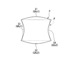
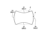
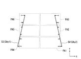
- FIG. 4A is a diagram schematically illustrating an example of a state in which the substrate P is deformed.
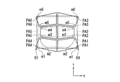
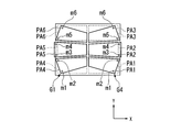
- FIG. 4B shows an example of the deformation states of the exposure areas PA1 to PA6 when the substrate P is deformed as shown in FIG. 4A and the positions of the alignment marks m1 to m6 of the first and fourth groups G1 and G4.
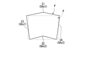
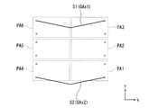
- FIGS. 5A, 6A, and 7A are diagrams schematically showing an example of a state in which the substrate P is deformed.
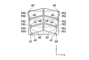
- FIGS. 5B, 6B, and 7B are FIGS. 5A, 6A, and 7A.
- FIGS. 4A to 7A the substrate P in an undeformed state is indicated by a broken line.
- 4B to 7B the exposure areas PA1 to PA6 that are not deformed are indicated by broken lines.
- the inventor of the invention categorizes (typifies) the deformation pattern of the substrate P into mainly four deformation patterns as shown in FIGS. 4A to 7A. I found out.
- the first X portion GAx1 (first side S1) and the second X portion GAx2 (second side S2) are deformed so as to bend outward with respect to the center of the substrate P.
- the first X portion GAx1 (first side S1) and the second X portion GAx2 (second side S2) are deformed so as to bend inward with respect to the center of the substrate P.
- the deformation pattern shown in FIG. 6A is deformed so that the central portion of the first X portion GAx1 (first side S1) protrudes outward with respect to the center of the substrate P, and the second X portion GAx2 (second side S2). ) Is deformed so as to protrude inward with respect to the center of the substrate P, and the end on the + Y side of the first Y portion GAy1 (third side S3) is ⁇ X than the end on the ⁇ Y side.
- This is a deformation pattern in which the + Y side end of the second Y portion GAy2 (fourth side S4) is located on the + X side with respect to the ⁇ Y side end.
- the deformation pattern shown in FIG. 7A is deformed so that the central portion of the first X portion GAx1 (first side S1) protrudes inward with respect to the center of the substrate P, and the second X portion GAx2 (second side S2). ) Is deformed so as to protrude outward with respect to the center of the substrate P, and the + Y side end of the first Y portion GAy1 (third side S3) is + X side than the ⁇ Y side end.
- the deformation pattern of the substrate P shown in FIG. 4A is appropriately referred to as a first deformation pattern
- the deformation pattern of the substrate P shown in FIG. 5A is appropriately referred to as a second deformation pattern
- the substrate shown in FIG. 6A is appropriately referred to as a third deformation pattern
- the deformation pattern of the substrate P illustrated in FIG. 7A is appropriately referred to as a fourth deformation pattern.
- the deformation of the outer edge area GA is at least one of the first side S1, the second side S2, the third side S3, and the fourth side S4 is taken as an example.
- the deformation of the first side S1 is a concept including the deformation of the first X portion GAx1
- the deformation of the second side S2 is a concept including the deformation of the second X portion GAx2
- the deformation is a concept including the deformation of the first Y portion GAy1
- the deformation of the fourth side S4 is a concept including the deformation of the second Y portion GAy2.
- each of the exposure areas PA1 to PA6 of the substrate P is deformed according to the first, second, third, and fourth deformation patterns of the substrate P.
- Each of the alignment marks m1 to m6 is displaced according to the first, second, third, and fourth deformation patterns of the substrate P.
- the alignment marks m1 to m6 of the first group G1 are displaced according to the deformation of the first Y portion GAy1 of the outer edge region GA, and the alignment marks m1 to m6 of the fourth group G4 are deformed of the second Y portion GAy2 of the outer edge region GA. Displaces according to
- the first deformation pattern is a deformation pattern that deforms so that each of the third side S3 and the fourth side S4 of the substrate P draws a quadratic curve.
- the first deformation pattern is a deformation pattern in which each of the third side S3 and the fourth side S4 can be expressed by a quadratic expression.
- the second deformation pattern is a deformation pattern that deforms so that each of the third side S3 and the fourth side S4 of the substrate P draws a quadratic curve.
- the second deformation pattern is a deformation pattern in which each of the third side S3 and the fourth side S4 can be expressed by a quadratic expression.
- the third deformation pattern is a deformation pattern that deforms so that each of the third side S3 and the fourth side S4 of the substrate P draws a straight line inclined with respect to the Y axis. is there.
- the third deformation pattern is a deformation pattern in which each of the third side S3 and the fourth side S4 can be expressed by a linear expression.
- the fourth deformation pattern is a deformation pattern that deforms so that each of the third side S3 and the fourth side S4 of the substrate P draws a straight line inclined with respect to the Y axis. is there.
- the fourth deformation pattern is a deformation pattern in which each of the third side S3 and the fourth side S4 can be expressed by a linear expression.
- the inventors of the present invention have found that the deformation states of the first side S1 and the second side S2 are determined according to the deformation states of the third side S3 and the fourth side S4. In other words, the inventor has found that there is a correlation between the deformation state of the first side S1 and the second side S2 and the deformation state of the third side S3 and the fourth side S4.
- the inventor obtains information on the deformation of the third side S3 and the fourth side S4, and based on the obtained result and a predetermined relational expression (correlation formula) determined in advance. It has been found that information relating to the deformation of the first side S1 and the second side S2 can be obtained (estimated).
- the deformation state includes at least one of the degree of deformation, the shape after deformation, and the deformation amount (difference between the undeformed state and the deformed state).
- information related to the deformation of the third side S3 and the fourth side S4 can be acquired by measuring the alignment marks m1 to m6.
- the alignment marks m1 to m6 are displaced according to the deformation of the substrate P.
- the alignment marks m1 to m6 of the first group G1 arranged in the first Y portion GAy1 including the third side S3 are displaced according to the deformation of the third side S3 (first Y portion GAy1) and include the fourth side S4.
- the alignment marks m1 to m6 of the fourth group G4 arranged in the second Y portion GAy2 are displaced according to the deformation of the fourth side S4 (second Y portion GAy2).
- the alignment system 9 can measure the alignment marks m1 to m6. Therefore, the control device 5 uses the alignment system 9 to measure the alignment marks m1 to m6 of the first group G1 of the substrate P, and acquires information related to the deformation of the third side S3 based on the measurement result. can do. Further, the control device 5 uses the alignment system 9 to measure the alignment marks m1 to m6 of the fourth group G4 of the substrate P, and acquires information related to the deformation of the fourth side S4 based on the measurement result. can do.
- the predetermined relational expression can be determined based on, for example, a preliminary experiment or a simulation result.
- the predetermined relational expression may be a primary expression or a secondary expression. Further, the predetermined relational expression may be a third or higher order polynomial. In the present embodiment, when the third side S3 and the fourth side S4 of the substrate P are deformed so as to draw a quadratic curve, a quadratic expression is adopted as a relational expression. In other words, when the deformation of the substrate P is at least one of the first deformation pattern and the second deformation pattern, a quadratic expression is adopted as the relational expression.
- a linear expression is adopted as a relational expression.
- the linear expression is adopted as the relational expression.
- a plurality of relational expressions corresponding to the deformation of the third side S3 (first Y portion GAy1) and the fourth side S4 (second Y portion GAy2) are prepared in advance.
- the plurality of relational expressions have different orders.
- at least a linear relational expression and a quadratic relational expression are prepared in advance, and a predetermined number of relational expressions are obtained from a plurality of relational expressions according to the deformation states of the third side S3 and the fourth side S4.
- a relational expression is selected.
- the control device 5 when it is acquired based on the measurement result of the alignment system 9 that the deformation state of the third side S3 and the fourth side S4 of the substrate P is a deformation state drawing a predetermined quadratic curve, the control device 5 The deformation state of the first side S1 and the second side S2 is acquired based on the acquired result (information on the predetermined quadratic curve) and a predetermined relational expression (secondary expression) set in advance. (Estimate).
- the control device 5 Based on the acquired result (information on a predetermined straight line) and a predetermined relational expression (primary expression) determined in advance, the deformation states of the first side S1 and the second side S2 are acquired (estimated). be able to.
- the predetermined relational expression is a quadratic expression
- the deformation state of the first side S1 and the second side S2 determined based on the relational expression is expressed by a quadratic expression.
- the predetermined relational expression is a quadratic expression
- the first side S1 and the second side S2 are deformed so as to draw a predetermined quadratic curve.
- the deformation state of the first side S1 and the second side S2 determined based on the relational expression is expressed by a linear expression.
- the predetermined relational expression is a linear expression
- the first side S1 and the second side S2 are deformed so as to draw a predetermined straight line (including two or more straight lines).
- the substrate P before exposure is transported (loaded) to the substrate holder 16 by a predetermined transport device.
- the substrate P is provided with alignment marks m1 to m6.
- the control device 5 uses the alignment system 9 to acquire information related to the deformation of the substrate P held by the substrate holding unit 16, and the alignment of the first group G1 of the substrates P held by the substrate holding unit 16 is performed.
- the marks m1 to m6 and the alignment marks m1 to m6 of the fourth group G4 are measured.
- control device 5 includes the substrate stage 2 that holds the substrate P by the substrate holder 16 so that the alignment marks m1 to m6 of the first group G1 are arranged in the detection areas AL1 to AL6 of the alignment system 9. Control the position.
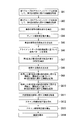
- the control device 5 measures the position of the substrate stage 2 using the laser interference system 6 and measures the alignment marks m1 to m6 of the first group G1 using the alignment system 9 (step SA1).
- control device 5 holds the substrate P 2 on the substrate holding unit 16 so that the alignment marks m1 to m6 of the fourth group G4 are arranged in the detection areas AL1 to AL6 of the alignment system 9. Control the position of the.
- the controller 5 measures the alignment marks m1 to m6 of the fourth group G4 using the alignment system 9 while measuring the position of the substrate stage 2 using the laser interference system 6 (step SA2).
- the control device 5 detects the positions of the alignment marks m1 to m6 of the first group G1 in the coordinate system defined by the laser interferometer system 6 and the fourth group in the coordinate system defined by the laser interferometer system 6.
- the positions of the alignment marks m1 to m6 of G4 can be obtained.
- control device 5 can acquire information related to the deformation of the third side S3 based on the measurement results of the alignment marks m1 to m6 of the first group G1 measured in step SA1. Further, the control device 5 can acquire information related to the deformation of the fourth side S4 based on the measurement results of the alignment marks m1 to m6 of the fourth group G4 measured in step SA2.
- control device 5 acquires information related to the deformation of the substrate P based on at least one of the measurement results of the alignment marks m1 to m6 of the first group G1 and the measurement results of the alignment marks m1 to m6 of the fourth group G4. can do.
- control device 5 can obtain the displacement amounts of the alignment marks m1 to m6 of the first group G1 and the displacement amounts of the alignment marks m1 to m6 of the fourth group G4 based on the measurement result of the alignment system 9. .
- the displacement amounts of the alignment marks m1 to m6 are the positions of the alignment marks m1 to m6 on the substrate P when the substrate P is not deformed and the alignment marks on the substrate P when the substrate P is deformed. The difference from the position of m1 to m6.
- the alignment marks m1 to m6 of the first group G1 are measured.
- the alignment marks m1 to m6 of the fourth group G4 are measured.
- the alignment marks of the fourth group G4 are measured.
- the alignment marks m1 to m6 of the first group G1 may be measured.
- control device 5 obtains a linear component of deformation of the substrate P based on the measurement results of the alignment marks m1 to m6 of the first and fourth groups G1 and G4 (step SA3).
- the deformation of the substrate P can be divided into a linear component and a non-linear component.
- the control apparatus 5 calculates
- the linear component of deformation of the substrate P includes, for example, a displacement amount from a reference lattice point in a coordinate system defined by the laser interferometer system 6, and a shift component in the X-axis direction of the substrate P with respect to the lattice point, It means at least one of a shift component related to the Y-axis direction, a rotation component related to the ⁇ Z direction, a scaling component related to the X-axis direction, a scaling component related to the Y-axis direction, and the orthogonality.
- step SA3 based on the linear component of deformation of the substrate P obtained in step SA3, the control device 5 corrects the linear correction value (linear correction amount) for the substrate P for correcting the linear component during exposure of the substrate P. Is obtained (step SA4).
- the linear correction value obtained in step SA4 is appropriately referred to as a plate linear correction value.
- control device 5 obtains a nonlinear component of the deformation of the substrate P based on the measurement results of the alignment marks m1 to m6 of the first and fourth groups G1 and G4 (step SA5).
- the control device 5 determines the substrate P based on the linear component of the deformation of the substrate P obtained in step SA3 and the measurement results of the alignment marks m1 to m6 of the first and fourth groups G1 and G4.
- the nonlinear component of the deformation can be obtained.
- the control device 5 acquires information related to the deformation of the substrate P including both the linear component and the nonlinear component based on the measurement results of the alignment marks m1 to m6 of the first and fourth groups G1 and G4. be able to.
- the control device 5 determines the deformation of the substrate P based on the difference between the information regarding the deformation of the substrate P obtained based on the measurement results of the alignment marks m1 to m6 and the linear component of the deformation of the substrate P obtained in step SA3.
- a nonlinear component can be obtained.
- the alignment marks m1 to m6 are displaced according to the deformation of the substrate P.
- the alignment marks m1 to m6 of the first group G1 are displaced mainly according to the deformation state of the third side S3, and the alignment marks m1 to m6 of the fourth group G4 close to the fourth side S4 are mainly the fourth side. It is displaced according to the deformation state of S4. Therefore, the control device 5 uses the alignment system 9 to measure the positions of the alignment marks m1 to m6 of the first and fourth groups G1 and G4 (for example, the position in the coordinate system defined by the laser interferometer system 6).
- the control device 5 determines that the substrate P has the first deformation pattern, the second deformation pattern, the third deformation pattern, and the fourth based on the measurement results of the alignment marks m1 to m6 of the first and fourth groups G1 and G4. It can be determined which of the deformation patterns the deformation pattern is deforming.
- the control device 5 determines that the fourth sides S3 and S4 are deformed so as to draw a quadratic curve, and it can be determined that the substrate P is deformed by at least one of the first deformation pattern and the second deformation pattern. Specifically, when it is determined that the line connecting the alignment marks m1 to m6 is bent inward with respect to the center of the substrate P as shown in FIG. If it is determined that the substrate P is deformed in the first deformation pattern, and it is determined that the substrate P is bent outward as shown in FIG. 5B, it may be determined that the substrate P is deformed in the second deformation pattern. it can.
- the control device 5 determines that the third and fourth sides S3 and S4 are deformed so as to draw a straight line inclined with respect to the Y axis, and the substrate P is in the third deformation pattern and the fourth deformation pattern. It can be determined that at least one of them is deformed. Specifically, when it is determined that the line connecting the alignment marks m1 to m6 is inclined as shown in FIG. 6B, the control device 5 determines that the substrate P is deformed in the third deformation pattern. If it is determined that the substrate P is inclined as shown in FIG. 7B, it can be determined that the substrate P is deformed in the fourth deformation pattern.
- the control device 5 deforms the deformation pattern of the first deformation pattern, the second deformation pattern, the third deformation pattern, or the fourth deformation pattern based on the measurement results of the alignment marks m1 to m6. Is obtained (step SA6).
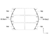
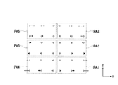
- FIG. 9 and 10 are diagrams schematically illustrating an example of a nonlinear component of deformation of the substrate P that is held by the substrate holding unit 16 and is deformed according to the second deformation pattern.
- FIG. 9 is a schematic diagram illustrating an example of a nonlinear component of deformation of the third side S3 and the fourth side S4 when the substrate P is deformed in the second deformation pattern
- FIG. 10 is a diagram illustrating the substrate P having the second deformation pattern. It is a schematic diagram which shows an example of the non-deformation component of 1st edge
- the third side S3 and the fourth side S4 draw a quadratic curve and can be expressed by a quadratic expression. Even when the non-linear component of the deformation of the substrate P is extracted in a state where the substrate P is deformed in the second deformation pattern, the third side S3 and the fourth side S4 draw a quadratic curve. Can be expressed as
- the nonlinear component regarding the X-axis direction at the third side S3 is represented by the following quadratic expression.
- ⁇ x1 (PY) a ⁇ PY 2 + b ⁇ PY + c (1)
- the nonlinear component regarding the X-axis direction at the fourth side S4 is represented by the following quadratic expression.
- PY represents a Y-axis direction component in a coordinate system (substrate coordinate system) on the substrate P.
- the control device 5 uses the coefficients a, b, c and the fourth side S4 of the equation (1) which is a quadratic expression representing the third side S3. It is possible to determine the coefficients d, e, and f of the equation (2) that is a quadratic equation representing.
- the control device 5 Based on the measurement results of the alignment marks m1 to m6 of the first group G1, the control device 5 performs a predetermined calculation process including a fitting process (for example, a fitting process using the least square method) with respect to the expression (1). , (1) coefficients a, b, and c can be obtained. Further, the control device 5 performs predetermined arithmetic processing including fitting processing with respect to the equation (2) based on the measurement results of the alignment marks m1 to m6 of the fourth group G4, thereby obtaining the coefficient of the equation (2). d, e, and f can be obtained.
- a fitting process for example, a fitting process using the least square method
- the expression (1) which is a quadratic expression representing the third side S3 and the expression (2) which is a quadratic expression representing the fourth side S4 are determined (step SA7). .
- control device 5 determines the first side S1 and the first side based on the formulas (1) and (2) representing the third side S3 and the fourth side S4, and a predetermined relational expression set in advance.
- a quadratic expression representing the two sides S2 is determined.
- the predetermined relational expression can be determined in advance based on, for example, a preliminary experiment or a result of simulation, and information on the relational expression is stored in the storage device 5R.
- the storage device 5R stores in advance a plurality of relational expressions corresponding to the deformation of the third side S3 and the fourth side S4.
- the control device 5 selects a predetermined relational expression from a plurality of relational expressions according to the deformation states of the third side S3 and the fourth side S4 acquired based on the measurement results of the alignment marks m1 to m6 (step SA8). ).
- control device 5 uses a plurality of relational expressions that are used to acquire information related to the deformation of the first side S1 and the second side S2 according to the deformation state of the third side S3 and the fourth side S4. Determine from the formula.
- the control device 5 selects a quadratic expression as a predetermined relational expression.
- the control device 5 acquires information regarding the deformation of the first side S1 based on the acquired information regarding the deformation of the third side S3 and the fourth side S4 and the following expression (3) which is a predetermined relational expression. (Step SA9).
- control device 5 described above (1), (1), (4) showing the deformation state of the third side S3 and the fourth side S4 acquired using the measurement result of the alignment system 9 and the arithmetic processing (fitting processing or the like).
- a quadratic curve (secondary expression) representing the first side S1 is obtained based on the expression (2) and the following expression (3).
- (3) Formula is a quadratic formula showing the nonlinear component regarding the X-axis direction in 1st edge
- ⁇ y1 (PX) ⁇ ⁇ (da) / 2 ⁇ PX 2 + h ⁇ PX + i (3)
- control device 5 obtains information on the deformation of the second side S2 based on the acquired information on the deformation of the third side S3 and the fourth side S4 and the following expression (4) which is a predetermined relational expression. Obtain (step SA10).
- control device 5 described above (1), (1), (4) showing the deformation state of the third side S3 and the fourth side S4 acquired using the measurement result of the alignment system 9 and the arithmetic processing (fitting processing or the like).
- a quadratic curve (secondary expression) representing the second side S2 is obtained based on the expression (2) and the following expression (4).
- (4) Formula is a quadratic formula showing the nonlinear component regarding the X-axis direction in 2nd edge
- ⁇ y2 (PX) ⁇ ⁇ (ad) / 2 ⁇ PX 2 + j ⁇ PX + k (4)
- PX represents an X-axis direction component in the coordinate system (substrate coordinate system) on the substrate P.
- the coefficients ⁇ and ⁇ are predetermined values (proportional counts) obtained from preliminary experiments or simulations.
- the first side When S1 and the second side S2 are expressed by a quadratic expression, the quadratic coefficients ( ⁇ ⁇ (da)) and ( ⁇ ⁇ (ad)) can be obtained.
- the first-order coefficients h and j and the zero-order coefficients i and k are the outer shape of the substrate P or the alignment marks m6 of the first and fourth groups G1 and G4. , M1 can be uniquely determined.
- the control device 5 includes the first to fourth sides S1 to S4 based on the measurement results of the alignment marks m1 to m6 of the first and fourth groups G1 and G4. Information regarding the deformation of the outer edge area GA can be acquired.
- control device 5 acquires information related to the deformation of the internal area UA of the substrate P (step SA11).
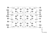
- control device 5 obtains a nonlinear component of deformation in each of the plurality of exposure areas PA1 to PA6 arranged in the internal area UA of the substrate P.
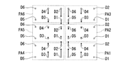
- a plurality of representative positions D1 to D6 are defined in each of the plurality of exposure areas PA1 to PA6.
- six exposure positions D1 to D6 are defined for one exposure area PA1 (PA2, PA3, PA4, PA5, PA6), but the number of positions may be five or less, Seven or more may be sufficient.
- control device 5 is based on two quadratic expressions ⁇ x1 (PY) and ⁇ x2 (PY) expressed by the expressions (1) and (2).
- Nonlinear components in the X-axis direction at each of the plurality of positions D1 to D6 are calculated by linear interpolation.
- control device 5 performs linear interpolation based on the two quadratic expressions ⁇ y1 (PX) and ⁇ y2 (PX) expressed by the expressions (3) and (4). Then, the nonlinear component in the Y-axis direction at each of the plurality of positions D1 to D6 is calculated.
- control device 5 corrects the non-linear component of deformation in each of the exposure regions PA1 to PA6 during the exposure of the substrate P based on the non-linear component of deformation in each of the exposure regions PA1 to PA6.
- a non-linear correction value (non-linear correction amount) for each of PA6 is obtained (step SA12).
- control device 5 corrects the linear component in each of the exposure areas PA1 to PA6 during the exposure of the substrate P based on the nonlinear component of the deformation of the substrate P in each of the exposure areas PA1 to PA6.
- a linear correction value (linear correction amount) for each of .about.PA6 is obtained (step SA13).
- the nonlinear correction value obtained in step SA12 is appropriately referred to as a scan nonlinear correction value
- the linear correction value obtained in step SA13 is appropriately referred to as a scan linear correction value.
- the control device 5 After obtaining the plate linear correction value, the scan nonlinear correction value, and the scan linear correction value, The control device 5 starts exposure of the substrate P held by the substrate holding unit 16 (step SA14). The controller 5 adjusts the exposure conditions based on the obtained correction value and exposes the substrate P. The control device 5 adjusts the exposure conditions so that the next pattern image is satisfactorily superimposed on the pattern already formed on the substrate P.
- the adjustment of the exposure condition includes, for example, at least one of a moving condition of the substrate P with respect to the projection regions PR1 to PR7 and a projection condition of pattern images of the projection optical systems PL1 to PL7.
- the moving condition of the substrate P includes at least one of the moving speed (scanning speed), acceleration, and moving direction of the substrate P.
- the projection condition of the pattern image includes at least one of a position (shift, rotation), size (magnification), and shape in the XY plane of each of the projection regions PR1 to PR7.
- the pattern image projection conditions include an adjustment including a shift adjustment mechanism, a rotation adjustment mechanism, a scaling adjustment mechanism, and the like as disclosed in, for example, Japanese Patent Application Laid-Open Nos. 2003-151880 and 2003-309053. It can be adjusted by the mechanism.
- the exposure apparatus EX of the present embodiment is an exposure apparatus that projects the pattern image of the mask M onto the substrate P while moving the mask M and the substrate P in a predetermined scanning direction (multi-lens scan). Exposure apparatus).
- the control device 5 controls the mask stage 1 and the substrate stage 2 to move the mask M and the substrate P in a predetermined scanning direction in the XY plane.
- the scanning direction (synchronous movement direction) of the substrate P is the X-axis direction
- the scanning direction (synchronous movement direction) of the mask M is also the X-axis direction.
- the control device 5 moves the substrate P in the X-axis direction with respect to the first to seventh projection regions PR1 to PR7 of the projection system PS, and in synchronization with the movement of the substrate P in the X-axis direction, While moving the mask M in the X-axis direction with respect to the first to seventh illumination regions IR1 to IR7 of IS, the illumination system IS illuminates the mask M with the exposure light EL, and from the mask M via the projection system PS. The substrate P is irradiated with the exposure light EL.
- the substrate P is exposed with the exposure light EL from the mask M irradiated to the first to seventh projection regions PR1 to PR7 of the first to seventh projection optical systems PL1 to PL7, and an image of the pattern of the mask M is formed. Projected onto the substrate P.
- the present embodiment it is possible to acquire information related to the deformation of the substrate P while suppressing the number of measurement points of the alignment mark. Therefore, it is possible to accurately acquire information related to the deformation of the substrate P while suppressing a decrease in throughput, and to suppress the occurrence of exposure failure and the generation of defective devices.
- the case where the substrate P is deformed with the second deformation pattern has been described as an example in the processing after step SA6. However, the same applies to the case where the substrate P is deformed with the first deformation pattern. By executing this process, information regarding the deformation of the substrate P can be acquired.
- step SA6 the processing after step SA6 has been described by taking as an example the case where the nonlinear component of the deformation of the substrate P includes the nonlinear component of the second deformation pattern (or the first deformation pattern).
- the nonlinear component of deformation of the substrate P includes the nonlinear component of the fourth deformation pattern.
- FIG. 13 is a flowchart showing an example of an exposure method according to the second embodiment. Note that the processing related to steps SA1 to SA6 shown in FIG. 13 is the same as the processing described in the first embodiment, and a description thereof will be omitted.
- FIGS. 14 and 15 are diagrams schematically showing an example of a non-linear component of deformation of the substrate P held by the substrate holding unit 16 and deformed in the fourth deformation pattern.
- FIG. 14 is a schematic diagram illustrating an example of a nonlinear component of deformation of the third side S3 and the fourth side S4 when the substrate P is deformed in the fourth deformation pattern
- FIG. 15 is a diagram illustrating the fourth deformation pattern of the substrate P. It is a schematic diagram which shows an example of the non-deformation component of 1st edge
- the third side S3 and the fourth side S4 can draw a straight line and be expressed by a linear expression. Even when the nonlinear component of the deformation of the substrate P is extracted in the state where the substrate P is deformed in the fourth deformation pattern, the third side S3 and the fourth side S4 draw a straight line and are expressed by a linear expression. be able to.
- the nonlinear component regarding the X-axis direction in the third side S3 is represented by the following linear expression.
- the nonlinear component regarding the X-axis direction at the fourth side S4 is represented by the following linear expression.
- PY represents a Y-axis direction component in a coordinate system (substrate coordinate system) on the substrate P.
- the control device 5 represents the coefficients a and b and the fourth side S4 of the equation (5), which is a linear expression representing the third side S3, based on the measurement result of the alignment marks m1 to m6 by the alignment system 9.
- the coefficients c and d in the equation (6), which is a linear equation, can be determined.
- the control device 5 executes predetermined arithmetic processing including fitting processing with respect to the equation (5), whereby the coefficients a and b of the equation (5) are obtained. Can be requested. Further, the control device 5 executes a predetermined calculation process including a fitting process with respect to the expression (6) based on the measurement results of the alignment marks m1 to m6 of the fourth group G4, thereby obtaining the coefficient of the expression (6). c and d can be obtained.
- the expression (5) that is a linear expression representing the third side S3 and the expression (6) that is a linear expression representing the fourth side S4 are determined (step SB7). .
- control device 5 determines the first side S1 and the first side based on the formulas (5) and (6) representing the third side S3 and the fourth side S4 and a predetermined relational expression. A linear expression representing the two sides S2 is determined.
- the predetermined relational expression can be determined in advance based on, for example, a preliminary experiment or a result of simulation, and information on the relational expression is stored in the storage device 5R.
- the storage device 5R stores in advance a plurality of relational expressions corresponding to the deformation of the third side S3 and the fourth side S4.
- the control device 5 selects a predetermined relational expression from a plurality of relational expressions according to the deformation states of the third side S3 and the fourth side S4 acquired based on the measurement results of the alignment marks m1 to m6 (step SB8). ).
- control device 5 uses a plurality of relational expressions that are used to acquire information related to the deformation of the first side S1 and the second side S2 according to the deformation state of the third side S3 and the fourth side S4. Determine from the formula.
- the control device 5 selects a linear expression as a predetermined relational expression.
- the control device 5 acquires information regarding the deformation of the first side S1 based on the acquired information regarding the deformation of the third side S3 and the fourth side S4 and the following expression (7) which is a predetermined relational expression. (Step SB9).
- ⁇ y (PX) ⁇ ⁇ (ca) / 2 ⁇ (L / 2 ⁇
- L is the dimension of the substrate P in the X-axis direction
- coefficient ⁇ is a predetermined value (proportional count) obtained from a preliminary experiment or simulation.
- control device 5 obtains information on the deformation of the second side S2 based on the acquired information on the deformation of the third side S3 and the fourth side S4 and the above-described expression (7) which is a predetermined relational expression. Obtain (step SB10).
- each of the information related to the deformation of the first side S1 and the information related to the deformation of the second side S2 is expressed by Expression (7).
- the first side S1 and the second side S2 are expressed by a linear expression
- the primary coefficient ( ⁇ ⁇ (ca) / 2) can be obtained.
- the zeroth order coefficient can be uniquely determined from the outer shape of the substrate P or the positions of the alignment marks m6 and m1 of the first and fourth groups G1 and G4.
- the control device 5 includes the first to fourth sides S1 to S4 based on the measurement results of the alignment marks m1 to m6 of the first and fourth groups G1 and G4. Information regarding the deformation of the outer edge area GA can be acquired.
- control device 5 acquires information related to the deformation of the internal area UA of the substrate P (step SB11).
- control device 5 obtains a nonlinear component of deformation in each of the plurality of exposure areas PA1 to PA6 arranged in the internal area UA of the substrate P.
- a plurality of representative positions D1 to D6 are defined in each of the plurality of exposure areas PA1 to PA6.
- six exposure positions D1 to D6 are defined for one exposure area PA1 (PA2, PA3, PA4, PA5, PA6), but the number of positions may be five or less, Seven or more may be sufficient.
- control device 5 is based on the two primary expressions ⁇ x1 (PY) and ⁇ x2 (PY) expressed by the expressions (5) and (6).
- Nonlinear components in the X-axis direction at each of the plurality of positions D1 to D6 are calculated by linear interpolation.
- control device 5 performs the Y-axis at each of the plurality of positions D1 to D6 by linear interpolation based on the linear expression ⁇ y (PX) expressed by the expression (7).
- a nonlinear component related to the direction is calculated.
- control device 5 corrects the non-linear component of deformation in each of the exposure regions PA1 to PA6 during the exposure of the substrate P based on the non-linear component of deformation in each of the exposure regions PA1 to PA6.
- a scan nonlinear correction value for each of .about.PA6 is obtained (step SB12).
- control device 5 corrects the linear component in each of the exposure areas PA1 to PA6 during the exposure of the substrate P based on the nonlinear component of the deformation of the substrate P in each of the exposure areas PA1 to PA6. Scan linear correction values for each of .about.PA6 are obtained (step SB13).
- the control device 5 After obtaining the plate linear correction value, the scan nonlinear correction value, and the scan linear correction value, The control device 5 starts exposure of the substrate P held by the substrate holding unit 16 (step SB14). The controller 5 adjusts the exposure conditions based on the obtained correction value and exposes the substrate P. The control device 5 adjusts the exposure conditions so that the next pattern image is satisfactorily superimposed on the pattern already formed on the substrate P.
- the case where the substrate P is deformed with the fourth deformation pattern has been described as an example in the processing after step SA6. However, the same applies to the case where the substrate P is deformed with the third deformation pattern. By executing this process, information regarding the deformation of the substrate P can be acquired.
- the information regarding the deformation of the first Y portion GAy1 disposed on the ⁇ X side with respect to the center of the substrate P and the information regarding the deformation of the second Y portion GAy2 disposed on the + X side are acquired. Based on the result and a predetermined relational expression, information related to the deformation of the X portion GAx is acquired. However, information related to the deformation of the first X portion GAx1 arranged on the + Y side with respect to the center of the substrate P and ⁇ Y Information regarding deformation of the Y portion GAy may be acquired based on a result of acquiring information regarding deformation of the second X portion GAx2 arranged on the side and a predetermined relational expression.
- the information about the deformation of the Y portion GAy extending in the Y-axis direction is acquired, and the X portion extending in the X-axis direction based on the acquired result and a predetermined relational expression.
- Information about deformation of GAx is acquired. For example, based on the result of acquiring information about deformation of Y portion GAy extending in the Y-axis direction and a predetermined relational expression, the X-axis and Y-axis are different. It is good also as acquiring the information regarding the deformation
- the deformation of the second part different from the first part based on the information on the deformation of the first part and the predetermined relational expression in the outer edge region GA of the substrate P. Information about can be obtained.
- the deformation of the portion arranged on one side for example, ⁇ X side
- the other side for example, + X side
- the information regarding the deformation of the portion to be arranged is acquired, but information regarding only one of the deformations may be acquired.
- the deformation of the second part different from the first part based on the information on the deformation of the first part and the predetermined relational expression in the outer edge region GA of the substrate P. Information about can be obtained.
- the outer shape of the substrate P is rectangular or square, but may be a rhombus or a parallelogram. Further, the outer shape of the substrate P may not be a quadrangle, may be a circle like a semiconductor wafer, or may be an ellipse.
- information related to the deformation of the substrate P is obtained by measuring the alignment marks m1 to m6 arranged on the substrate P.
- the end (outer shape) of the substrate P is optically measured. It is good also as acquiring the information regarding the deformation
- the substrate P in the above-described embodiment not only a glass substrate for a display device but also a semiconductor wafer for manufacturing a semiconductor device, a ceramic wafer for a thin film magnetic head, or an original mask (reticle) used in an exposure apparatus ( Synthetic quartz, silicon wafer) or the like is applied.
- a step-and-scan type scanning exposure apparatus that scans and exposes the substrate P with the exposure light EL through the pattern of the mask M by moving the mask M and the substrate P synchronously.
- the pattern of the mask M is collectively exposed while the mask M and the substrate P are stationary, and is applied to a step-and-repeat type projection exposure apparatus (stepper) that sequentially moves the substrate P stepwise.
- the present invention also relates to a twin-stage type exposure having a plurality of substrate stages as disclosed in US Pat. No. 6,341,007, US Pat. No. 6,208,407, US Pat. No. 6,262,796, and the like. It can also be applied to devices.
- the present invention relates to a substrate stage for holding a substrate as disclosed in US Pat. No. 6,897,963, European Patent Application No. 1713113, etc., and a reference mark without holding the substrate.
- the present invention can also be applied to an exposure apparatus that includes a formed reference member and / or a measurement stage on which various photoelectric sensors are mounted.
- An exposure apparatus including a plurality of substrate stages and measurement stages can be employed.
- the type of the exposure apparatus EX is not limited to an exposure apparatus for manufacturing a liquid crystal display element or a display, but an exposure apparatus for manufacturing a semiconductor element that exposes a semiconductor element pattern on a substrate P, a thin film magnetic head, an image sensor (CCD)
- the present invention can be widely applied to an exposure apparatus for manufacturing a micromachine, MEMS, DNA chip, reticle, mask, or the like.
- the position information of each stage is measured using an interferometer system including a laser interferometer.
- an interferometer system including a laser interferometer.
- the present invention is not limited to this.
- a scale diffiffraction grating provided in each stage You may use the encoder system which detects this.
- a light-transmitting mask in which a predetermined light-shielding pattern (or phase pattern / dimming pattern) is formed on a light-transmitting substrate is used.
- a variable shaped mask also called an electronic mask, an active mask, or an image generator
- a pattern forming apparatus including a self-luminous image display element may be provided instead of the variable molding mask including the non-luminous image display element.
- the exposure apparatus EX is manufactured by assembling various subsystems including the constituent elements recited in the claims of the present application so as to maintain predetermined mechanical accuracy, electrical accuracy, and optical accuracy. Is done. To ensure these various accuracies, before and after this assembly, various optical systems are adjusted to achieve optical accuracy, various mechanical systems are adjusted to achieve mechanical accuracy, and various electrical systems are Adjustments are made to achieve electrical accuracy.
- the assembly process from the various subsystems to the exposure apparatus includes mechanical connection, electrical circuit wiring connection, pneumatic circuit piping connection and the like between the various subsystems. Needless to say, there is an assembly process for each subsystem before the assembly process from the various subsystems to the exposure apparatus. When the assembly process of the various subsystems to the exposure apparatus is completed, comprehensive adjustment is performed to ensure various accuracies as the entire exposure apparatus.
- the exposure apparatus is preferably manufactured in a clean room where the temperature, cleanliness, etc. are controlled.
- a microdevice such as a semiconductor device includes a step 201 for designing the function and performance of the microdevice, a step 202 for producing a mask (reticle) based on the design step, and a substrate which is a base material of the device.
- Manufacturing step 203 including substrate processing (exposure processing) including exposing the substrate with exposure light using a mask pattern and developing the exposed substrate (photosensitive material) according to the above-described embodiment
- the substrate is manufactured through a substrate processing step 204, a device assembly step (including processing processes such as a dicing process, a bonding process, and a packaging process) 205, an inspection step 206, and the like.
- the photosensitive material is developed to form an exposure pattern layer (developd photosensitive material layer) corresponding to the mask pattern, and the substrate is processed through the exposure pattern layer. It is.
Landscapes
- Physics & Mathematics (AREA)
- General Physics & Mathematics (AREA)
- Exposure And Positioning Against Photoresist Photosensitive Materials (AREA)
- Container, Conveyance, Adherence, Positioning, Of Wafer (AREA)
- Exposure Of Semiconductors, Excluding Electron Or Ion Beam Exposure (AREA)
Abstract
露光光で基板を露光する露光方法は、基板の端を含む外縁領域の第1部分の変形に関する情報を取得することと、取得した結果と、所定の関係式とに基づいて、第1部分と異なる外縁領域の第2部分の変形に関する情報を取得することと、取得した第1部分及び第2部分の変形に関する情報に基づいて、基板を露光することと、を含む。
Description
本発明は、露光方法、露光装置、及びデバイス製造方法に関する。
本願は、2011年4月5日に出願された日本国特願2011-083594号に基づき優先権を主張し、その内容をここに援用する。
本願は、2011年4月5日に出願された日本国特願2011-083594号に基づき優先権を主張し、その内容をここに援用する。
フラットパネルディスプレイ等の電子デバイスの製造工程において、例えば特許文献1に開示されているような、露光光で基板を露光する露光装置が使用される。デバイスは、基板上に複数のパターン(パターン化された膜)を積層することによって形成される。露光処理において、基板に既に形成されているパターンに次のパターンの像を重ね合わせる際、基板のアライメントマークを計測し、そのアライメントマークの計測結果に基づいて、基板と次のパターンの像との位置合わせを行うアライメント処理が実行される。
露光処理において、基板が変形すると、パターンの重ね合わせ精度が低下し、その結果、露光不良の発生、及び不良デバイスの発生をもたらす。基板が変形した場合でも、パターンの重ね合わせ精度の低下を抑制するために、基板の変形に関する情報を精確に取得することが有効である。基板の変形が非線形成分(非線形歪み)を含む場合、アライメントマークの計測点数を多くすることによって、その非線形歪みを含む基板の変形に関する情報を精確に取得することができる。しかし、アライメントマークの計測点数を多くした場合、その計測のために時間を要し、スループットが低下してしまう可能性がある。
本発明に係る態様は、スループットの低下を抑制しつつ、基板の変形に関する情報を精確に取得して露光不良の発生を抑制できる露光方法及び露光装置を提供することを目的とする。また本発明に係る態様は、スループットの低下を抑制しつつ、不良デバイスの発生を抑制できるデバイス製造方法を提供することを目的とする。
本発明に係る一態様は、露光光で基板を露光する露光方法であって、基板の端を含む外縁領域の第1部分の変形に関する情報を取得することと、取得した結果と、所定の関係式とに基づいて、第1部分と異なる外縁領域の第2部分の変形に関する情報を取得することと、取得した第1部分及び第2部分の変形に関する情報に基づいて、基板を露光することと、を含む。
本発明に係る一態様のデバイス製造方法は、上記態様の露光方法を用いて基板を露光することと、露光された基板を現像することと、を含む。
本発明に係る一態様は、露光光で基板を露光する露光装置であって、基板の端を含む外縁領域の第1部分の変形に関する情報を取得する第1取得装置と、第1取得装置で取得した結果と、所定の関係式とに基づいて、第1部分と異なる外縁領域の第2部分の変形に関する情報を取得する第2取得装置と、を備え、取得した第1部分及び第2部分の変形に関する情報に基づいて、基板を露光する。
本発明に係る一態様のデバイス製造方法は、上記露光装置を用いて基板を露光することと、露光された基板を現像することと、を含む。
本発明に係る態様によれば、スループットの低下を抑制しつつ、露光不良の発生を抑制できる。また本発明に係る態様によれば、スループットの低下を抑制しつつ、不良デバイスの発生を抑制できる。
以下、本発明の実施形態について図面を参照しながら説明するが、本発明はこれに限定されない。以下の説明においては、XYZ直交座標系を設定し、このXYZ直交座標系を参照しつつ各部の位置関係について説明する。水平面内の所定方向をX軸方向、水平面内においてX軸方向と直交する方向をY軸方向、X軸方向及びY軸方向のそれぞれと直交する方向(すなわち鉛直方向)をZ軸方向とする。また、X軸、Y軸、及びZ軸まわりの回転(傾斜)方向をそれぞれ、θX、θY、及びθZ方向とする。
<第1実施形態>
第1実施形態について説明する。図1は、第1実施形態に係る露光装置EXの一例を示す概略構成図、図2は、斜視図である。図1及び図2において、露光装置EXは、マスクMを保持して移動可能なマスクステージ1と、基板Pを保持して移動可能な基板ステージ2と、マスクステージ1を移動する駆動システム3と、基板ステージ2を移動する駆動システム4と、マスクMを露光光ELで照明する照明システムISと、露光光ELで照明されたマスクMのパターンの像を基板Pに投影する投影システムPSと、露光装置EX全体の動作を制御する制御装置5と、制御装置5に接続され、露光に関する各種の情報を記憶する記憶装置5Rとを備えている。
第1実施形態について説明する。図1は、第1実施形態に係る露光装置EXの一例を示す概略構成図、図2は、斜視図である。図1及び図2において、露光装置EXは、マスクMを保持して移動可能なマスクステージ1と、基板Pを保持して移動可能な基板ステージ2と、マスクステージ1を移動する駆動システム3と、基板ステージ2を移動する駆動システム4と、マスクMを露光光ELで照明する照明システムISと、露光光ELで照明されたマスクMのパターンの像を基板Pに投影する投影システムPSと、露光装置EX全体の動作を制御する制御装置5と、制御装置5に接続され、露光に関する各種の情報を記憶する記憶装置5Rとを備えている。
マスクMは、基板Pに投影されるデバイスパターンが形成されたレチクルを含む。基板Pは、例えばガラスプレート等の基材と、その基材上に形成された感光膜(塗布された感光剤)とを含む。本実施形態において、基板Pの外形は、四角形である。本実施形態において、基板Pは、大型のガラスプレートを含み、その基板Pの一辺のサイズは、例えば500mm以上である。本実施形態においては、基板Pの基材として、一辺が約3000mmの四角形のガラスプレートを用いる。
また、本実施形態の露光装置EXは、マスクステージ1及び基板ステージ2の位置情報を計測する干渉計システム6と、マスクMの表面(下面、パターン形成面)の位置情報を検出する第1検出システム7と、基板Pの表面(露光面、感光面)の位置情報を検出する第2検出システム8と、基板P上のアライメントマーク計測を実行するアライメントシステム9とを備えている。
また、露光装置EXは、ボディ13を備えている。ボディ13は、例えばクリーンルーム内の支持面(例えば床面)FL上に防振台BLを介して配置されたベースプレート10と、ベースプレート10上に配置された第1コラム11と、第1コラム11上に配置された第2コラム12とを有する。本実施形態において、ボディ13は、投影システムPS、マスクステージ1、及び基板ステージ2のそれぞれを支持する。本実施形態において、投影システムPSは、定盤14を介して、第1コラム11に支持される。マスクステージ1は、第2コラム12に対して移動可能に支持される。基板ステージ2は、ベースプレート10に対して移動可能に支持される。
本実施形態において、投影システムPSは、複数の投影光学系を有する。照明システムISは、複数の投影光学系に対応する複数の照明モジュールを有する。また、本実施形態の露光装置EXは、マスクMと基板Pとを所定の走査方向に同期移動しながら、マスクMのパターンの像を基板Pに投影する。すなわち、本実施形態の露光装置EXは、所謂、マルチレンズ型スキャン露光装置である。
本実施形態において、投影システムPSは、7つの投影光学系PL1~PL7を有し、照明システムISは、7つの照明モジュールIL1~IL7を有する。なお、投影光学系及び照明モジュールの数は7つに限定されず、例えば投影システムPSが、投影光学系を11個有し、照明システムISが、照明モジュールを11個有してもよい。
照明システムISは、所定の照明領域IR1~IR7に露光光ELを照射可能である。
照明領域IR1~IR7は、各照明モジュールIL1~IL7から射出される露光光ELの照射領域に含まれている。本実施形態において、照明システムISは、異なる7つの照明領域IR1~IR7のそれぞれを露光光ELで照明する。照明システムISは、マスクMのうち照明領域IR1~IR7に配置された部分を、均一な照度分布の露光光ELで照明する。本実施形態においては、照明システムISから射出される露光光ELとして、例えば水銀ランプから射出される輝線(g線、h線、i線)を用いる。
照明領域IR1~IR7は、各照明モジュールIL1~IL7から射出される露光光ELの照射領域に含まれている。本実施形態において、照明システムISは、異なる7つの照明領域IR1~IR7のそれぞれを露光光ELで照明する。照明システムISは、マスクMのうち照明領域IR1~IR7に配置された部分を、均一な照度分布の露光光ELで照明する。本実施形態においては、照明システムISから射出される露光光ELとして、例えば水銀ランプから射出される輝線(g線、h線、i線)を用いる。
マスクステージ1は、マスクMを保持した状態で、照明領域IR1~IR7に対して移動可能である。マスクステージ1は、マスクMを保持可能なマスク保持部15を有する。
マスク保持部15は、マスクMを真空吸着可能なチャック機構を含み、マスクMをリリース可能に保持する。本実施形態において、マスク保持部15は、マスクMの下面(パターン形成面)とXY平面とがほぼ平行となるように、マスクMを保持する。駆動システム3は、例えばリニアモータを含み、第2コラム12のガイド面12G上においてマスクステージ1を移動可能である。本実施形態において、マスクステージ1は、駆動システム3の作動により、マスク保持部15でマスクMを保持した状態で、ガイド面12G上を、X軸、Y軸、及びθZ方向の3つの方向に移動可能である。
マスク保持部15は、マスクMを真空吸着可能なチャック機構を含み、マスクMをリリース可能に保持する。本実施形態において、マスク保持部15は、マスクMの下面(パターン形成面)とXY平面とがほぼ平行となるように、マスクMを保持する。駆動システム3は、例えばリニアモータを含み、第2コラム12のガイド面12G上においてマスクステージ1を移動可能である。本実施形態において、マスクステージ1は、駆動システム3の作動により、マスク保持部15でマスクMを保持した状態で、ガイド面12G上を、X軸、Y軸、及びθZ方向の3つの方向に移動可能である。
投影システムPSは、所定の投影領域PR1~PR7に露光光ELを照射可能である。
投影領域PR1~PR7は、各投影光学系PL1~PL7から射出される露光光ELの照射領域に相当する。本実施形態において、投影システムPSは、異なる7つの投影領域PR1~PR7のそれぞれにパターンの像を投影する。投影光学システムPSは、基板Pのうち投影領域PR1~PR7に配置された部分に、マスクMのパターンの像を所定の投影倍率で投影する。
投影領域PR1~PR7は、各投影光学系PL1~PL7から射出される露光光ELの照射領域に相当する。本実施形態において、投影システムPSは、異なる7つの投影領域PR1~PR7のそれぞれにパターンの像を投影する。投影光学システムPSは、基板Pのうち投影領域PR1~PR7に配置された部分に、マスクMのパターンの像を所定の投影倍率で投影する。
基板ステージ2は、基板Pを保持した状態で、投影領域PR1~PR7に対して移動可能である。基板ステージ2は、基板Pを保持可能な基板保持部16を有する。基板保持部16は、基板Pを真空吸着可能なチャック機構を含み、基板Pをリリース可能に保持する。本実施形態において、基板保持部16は、基板Pの表面(露光面)とXY平面とがほぼ平行となるように、基板Pを保持する。駆動システム4は、例えばリニアモータを含み、ベースプレート10のガイド面10G上において基板ステージ2を移動可能である。本実施形態において、基板ステージ2は、駆動システム4の作動により、基板保持部16で基板Pを保持した状態で、ガイド面10G上を、X軸、Y軸、Z軸、θX、θY、及びθZ方向の6つの方向に移動可能である。
干渉計システム6は、マスクステージ1の位置情報を計測するレーザ干渉計ユニット6Aと、基板ステージ2の位置情報を計測するレーザ干渉計ユニット6Bとを有する。レーザ干渉計ユニット6Aは、マスクステージ1に配置された計測ミラー1Rを用いて、マスクステージ1の位置情報を計測可能である。レーザ干渉計ユニット6Bは、基板ステージ2に配置された計測ミラー2Rを用いて、基板ステージ2の位置情報を計測可能である。
本実施形態において、干渉計システム6は、レーザ干渉計ユニット6A,6Bを用いて、X軸、Y軸、及びθX方向に関するマスクステージ1及び基板ステージ2それぞれの位置情報を計測可能である。基板Pの露光処理を実行するとき、あるいは所定の計測処理を実行するとき、制御装置5は、干渉計システム6の計測結果に基づいて、駆動システム3,4を作動し、マスクステージ1(マスクM)、及び基板ステージ2(基板P)の位置制御を実行する。
本実施形態において、干渉計システム6は、レーザ干渉計ユニット6A,6Bを用いて、X軸、Y軸、及びθX方向に関するマスクステージ1及び基板ステージ2それぞれの位置情報を計測可能である。基板Pの露光処理を実行するとき、あるいは所定の計測処理を実行するとき、制御装置5は、干渉計システム6の計測結果に基づいて、駆動システム3,4を作動し、マスクステージ1(マスクM)、及び基板ステージ2(基板P)の位置制御を実行する。
アライメントシステム9は、基板Pに設けられているアライメントマークを計測する。
アライメントシステム9は、所謂、オフアクシス方式のアライメントシステムであり、基板ステージ2に保持された基板Pの表面と対向配置される複数の顕微鏡9A~9Fを有する。顕微鏡9A~9Fのそれぞれは、検出領域AL1~AL6に検出光を照射する投射部と、検出領域AL1~AL6に配置されたアライメントマークの光学像を取得可能な受光部とを有する。
アライメントシステム9は、所謂、オフアクシス方式のアライメントシステムであり、基板ステージ2に保持された基板Pの表面と対向配置される複数の顕微鏡9A~9Fを有する。顕微鏡9A~9Fのそれぞれは、検出領域AL1~AL6に検出光を照射する投射部と、検出領域AL1~AL6に配置されたアライメントマークの光学像を取得可能な受光部とを有する。
制御装置5は、投影システムPSにより形成されるマスクMのパターンの像を、基板Pに既に形成されているパターンに重ね合わせるように、露光処理を実行する。露光処理の際、制御装置5は、基板Pのアライメントマークを計測し、そのアライメントマークの計測結果に基づいて、基板PとマスクMのパターンの像との位置合わせを行うアライメント処理を実行する。
図3は、投影システムPSの投影領域PR1~PR7と、アライメントシステム9の検出領域AL1~AL6と、基板Pとの位置関係の一例を示す模式図であり、基板Pの表面を含む平面内の位置関係を示している。
図3に示すように、本実施形態において、基板Pの外形は、四角形である。本実施形態において、基板Pの外形は、X軸方向に長い長方形である。なお、基板Pの外形が、正方形でもよいし、Y軸方向に長い長方形でもよい。
基板Pは、4つの辺を有する。基板Pは、X軸方向とほぼ平行な2つの辺S1、S2と、Y軸方向とほぼ平行な2つの辺S3、S4とを有する。
以下の説明において、基板Pが有するX軸方向とほぼ平行な2つの辺S1、S2のうち、一方の辺を適宜、第1辺S1と称し、他方の辺を適宜、第2辺S2と称する。本実施形態において、第1辺S1は、+Y側の辺であり、第2辺S2は、-Y側の辺である。また、基板Pが有するY軸方向とほぼ平行な2つの辺S3、S4のうち、一方の辺を適宜、第3辺S3、と称し、他方の辺を適宜、第4辺S4、と称する。本実施形態において、第3辺S3は、-X側の辺であり、第4辺S4は、+X側の辺である。
また、以下の説明において、基板Pの端(辺)を含む基板Pの外縁の領域を適宜、外縁領域GA、と称する。また、基板Pのうち、外縁領域GAの内側の領域を適宜、内部領域UA、と称する。内部領域UAは、基板Pの中心を含む領域である。外縁領域GAは、内部領域UAの周囲に配置される領域である。
また、外縁領域GAのうち、Y軸方向に長い(延在する)部分を適宜、Y部分GAy、と称し、X軸方向に延在する部分を適宜、X部分GAx、と称する。
本実施形態において、Y部分GAyは、Y軸方向に延在する第3辺S3を含む第1Y部分GAy1と、Y軸方向に延在する第4辺S4を含む第2Y部分GAy2とを含む。X部分GAxは、X軸方向に延在する第1辺S1を含む第1X部分GAx1と、X軸方向に延在する第2辺S2を含む第2X部分GAx2とを含む。Y部分GAyのうち、第1Y部分GAy1は、基板Pの中心に対して-X側に配置され、第2Y部分GAy2は、基板Pの中心に対して+X側に配置される。X部分GAxのうち、第1X部分GAx1は、基板Pの中心に対して+Y側に配置され、第2X部分GAx2は、基板Pの中心に対して-Y側に配置される。
図3に示すように、本実施形態おいて、基板Pの表面は、マスクMのパターンの像が投影される複数の露光領域(被処理領域)PA1~PA6を有する。本実施形態において、基板Pの表面は、6つの露光領域PA1~PA6を有する。露光領域PA1、PA2、PA3が、Y軸方向にほぼ等間隔で離れて配置され、露光領域PA4、PA5、PA6が、Y軸方向にほぼ等間隔で離れて配置されている。露光領域PA1、PA2、PA3は、露光領域PA4、PA5、PA6に対して+X側に配置されている。露光領域PA1~PA6は、基板Pの内部領域UAに配置される。
本実施形態において、投影領域PR1~PR7のそれぞれは、XY平面内において台形である。本実施形態において、投影光学系PL1、PL3、PL5、PL7による投影領域PR1、PR3、PR5、PR7が、Y軸方向にほぼ等間隔で配置され、投影光学系PL2、PL4、PL6による投影領域PR2、PR4、PR6が、Y軸方向にほぼ等間隔で配置されている。投影領域PR1、PR3、PR5、PR7は、投影領域PR2、PR4、PR6に対して-X側に配置されている。また、Y軸方向に関して、投影領域PR1、PR3、PR5、PR7の間に、投影領域PR2、PR4、PR6がそれぞれ配置される。
本実施形態において、顕微鏡9A~9Fによる検出領域AL1~AL6が、投影領域PR1~PR7に対して-X側に配置されている。検出領域AL1~AL6は、Y軸方向に離れて配置される。複数の検出領域AL1~AL6のうち、Y軸方向に関して外側2つの検出領域AL1(AL5)と検出領域AL2(AL6)との間隔は、複数の露光領域PA1~PA6のうち、Y軸方向に関して外側2つの露光領域PA1(PA4)の-Y側のエッジと露光領域PA3(PA6)の+Y側のエッジとの間隔とほぼ等しい。
アライメントシステム9は、基板Pに設けられている複数のアライメントマークm1~m6を検出可能である。本実施形態において、基板P上にはY軸方向に6つのアライメントマークm1~m6が配置され、それらアライメントマークm1~m6のグループが、X軸方向に4箇所に配置されている。1つのグループにおいて、アライメントマークm1~m6のそれぞれは、X軸方向に関して離れて配置される。4つのグループのそれぞれは、Y軸方向に関して離れて配置される。
以下の説明において、アライメントマークm1~m6の4つのグループのうち、最も-X側のグループを適宜、第1グループG1、と称し、第1グループG1に次いで-X側のグループを適宜、第2グループG2、と称し、第2グループG2に次いで-X側のグループを適宜、第3グループG3、と称し、最も+X側のグループを適宜、第4グループG4、と称する。第1~第4グループG1~G4のアライメントマークm1~m6のうち、第1グループG1のアライメントマークm1~m4が、最も第3辺S3に近く、第4グループG4のアライメントマークm1~m4が、最も第4辺S4に近い。
第2、第3グループG2、G3のアライメントマークm1~m6は、基板Pの内部領域UAに配置される。第1、第4グループG1、G4のアライメントマークm1~m6は、基板Pの外縁領域GAに配置される。本実施形態において、第1,第4グループG1、G4のアライメントマークm1~m6は、外縁領域GAのうち、Y部分GAyに配置される。本実施形態において、第1グループG1のアライメントマークm1~m6は、Y部分GAyのうち、第1Y部分GAy1に配置され、第4グループG4のアライメントマークm1~m6は、Y部分GAyのうち、第2Y部分GAy2に配置される。
なお、アライメントマークm1~m6のうち、アライメントマークm1,m2は、露光領域PA1,PA4の各両端部に隣接して設けられ、アライメントマークm3,m4は、露光領域PA2,PA5の各両端部に隣接して設けられ、アライメントマークm5,m6は、露光領域PA3,PA6の各両端部に隣接して設けられている。
本実施形態においては、基板P上においてY軸方向に離れて配置された6つのアライメントマークm1~m6に対応して、顕微鏡9A~9F(検出領域AL1~AL6)が配置されている。顕微鏡9A~9Fは、アライメントマークm1~m6が検出領域AL1~AL6に同時に配置されるように設けられている。アライメントシステム9は、顕微鏡9A~9Fを用いて、6つのアライメントマークm1~m6を同時に検出可能である。換言すれば、アライメントシステム9は、第1グループG1のアライメントマークm1~m6を同時に検出可能であり、第2グループG2のアライメントマークm1~m6を同時に検出可能であり、第3グループG3のアライメントマークm1~m6を同時に検出可能であり、第4グループG4のアライメントマークm1~m6を同時に検出可能である。
ところで、基板Pは、変形する可能性がある。基板Pは、例えば露光処理の前後に行われる各種のプロセス処理によって加熱される場合がある。その結果、基板Pの変形(熱変形)が発生する可能性がある。また、基板保持部16の保持状態に起因して、基板Pの変形(歪み変形)が発生する可能性がある。なお、基板保持部16の保持状態は、例えば基板保持部16に設けられている吸着機構の吸着むらを含む。なお、基板Pが変形する原因は、プロセス処理、及び基板保持部16の保持状態に限られない。例えば特開2001-332600号公報等に開示されているようなトレイに基板Pを載せた状態で基板保持部16に基板Pを搬入(ロード)する場合、そのトレイの形状、変形等に依存して、基板保持部16に搬入されて保持された基板Pが変形する可能性もある。
図4Aは、基板Pが変形している状態の一例を模式的に示す図である。図4Bは、図4Aに示すように基板Pが変形しているときの露光領域PA1~PA6それぞれの変形の状態、及び第1,第4グループG1,G4のアライメントマークm1~m6の位置の一例を模式的に示す図である。同様に、図5A、図6A、図7Aは、基板Pが変形している状態の一例を模式的に示す図であり、図5B、図6B、図7Bは、図5A、図6A、図7Aに示すように基板Pが変形しているときの露光領域PA1~PA6それぞれの変形の状態、及び第1,第4グループG1,G4のアライメントマークm1~m6の位置の一例を模式的に示す図である。なお、図4A~図7Aにおいて、変形していない状態の基板Pが破線で示されている。図4B~図7Bにおいて、変形していない状態の露光領域PA1~PA6が破線で示されている。
本出願に係る発明の発明者は、基板Pが変形する場合、その基板Pの変形パターンは、図4A~図7Aのそれぞれに示すように、主に4つの変形パターンに分類(類型化)されることを見出した。
図4Aに示す変形パターンは、第1X部分GAx1(第1辺S1)及び第2X部分GAx2(第2辺S2)が、基板Pの中心に対して外側に向かって曲がるように変形し、第1Y部分GAy1(第3辺S3)及び第2Y部分GAy2(第4辺S4)が、基板Pの中心に対して内側に向かって曲がるように変形する変形パターンである。
図5Aに示す変形パターンは、第1X部分GAx1(第1辺S1)及び第2X部分GAx2(第2辺S2)が、基板Pの中心に対して内側に向かって曲がるように変形し、第1Y部分GAy1(第3辺S3)及び第2Y部分GAy2(第4辺S4)が、基板Pの中心に対して外側に向かって曲がるように変形する変形パターンである。
図6Aに示す変形パターンは、第1X部分GAx1(第1辺S1)の中央部が、基板Pの中心に対して外側に向かって突出するように変形し、第2X部分GAx2(第2辺S2)の中央部が、基板Pの中心に対して内側に向かって突出するように変形し、第1Y部分GAy1(第3辺S3)の+Y側の端が、-Y側の端よりも-X側に位置し、第2Y部分GAy2(第4辺S4)の+Y側の端が、-Y側の端よりも+X側に位置する変形パターンである。
図7Aに示す変形パターンは、第1X部分GAx1(第1辺S1)の中央部が、基板Pの中心に対して内側に向かって突出するように変形し、第2X部分GAx2(第2辺S2)の中央部が、基板Pの中心に対して外側に向かって突出するように変形し、第1Y部分GAy1(第3辺S3)の+Y側の端が、-Y側の端よりも+X側に位置し、第2Y部分GAy2(第4辺S4)の+Y側の端が、-Y側の端よりも-X側に位置する変形パターンである。
以下の説明において、図4Aに示す基板Pの変形パターンを適宜、第1変形パターン、と称し、図5Aに示す基板Pの変形パターンを適宜、第2変形パターン、と称し、図6Aに示す基板Pの変形パターンを適宜、第3変形パターン、と称し、図7Aに示す基板Pの変形パターンを適宜、第4変形パターン、と称する。
また、以下の説明においては、簡単のため、外縁領域GAの変形が、第1辺S1、第2辺S2、第3辺S3、及び第4辺S4の少なくとも一つの変形である場合を例にして説明するが、第1辺S1の変形は、第1X部分GAx1の変形を含む概念であり、第2辺S2の変形は、第2X部分GAx2の変形を含む概念であり、第3辺S3の変形は、第1Y部分GAy1の変形を含む概念であり、第4辺S4の変形は、第2Y部分GAy2の変形を含む概念である。
図4B、図5B、図6B、図7Bに示すように、基板Pの露光領域PA1~PA6のそれぞれは、基板Pの第1、第2、第3、第4変形パターンに応じて変形する。また、アライメントマークm1~m6のそれぞれは、基板Pの第1、第2、第3、第4変形パターンに応じて変位する。第1グループG1のアライメントマークm1~m6は、外縁領域GAの第1Y部分GAy1の変形に応じて変位し、第4グループG4のアライメントマークm1~m6は、外縁領域GAの第2Y部分GAy2の変形に応じて変位する。
図4Aに示すように、本実施形態において、第1変形パターンは、基板Pの第3辺S3及び第4辺S4のそれぞれが2次曲線を描くように変形する変形パターンである。換言すれば、第1変形パターンは、第3辺S3及び第4辺S4のそれぞれを2次式で表すことができる変形パターンである。
図5Aに示すように、本実施形態において、第2変形パターンは、基板Pの第3辺S3及び第4辺S4のそれぞれが2次曲線を描くように変形する変形パターンである。換言すれば、第2変形パターンは、第3辺S3及び第4辺S4のそれぞれを2次式で表すことができる変形パターンである。
図6Aに示すように、本実施形態において、第3変形パターンは、基板Pの第3辺S3及び第4辺S4のそれぞれがY軸に対して傾斜した直線を描くように変形する変形パターンである。換言すれば、第3変形パターンは、第3辺S3及び第4辺S4のそれぞれを1次式で表すことができる変形パターンである。
図7Aに示すように、本実施形態において、第4変形パターンは、基板Pの第3辺S3及び第4辺S4のそれぞれがY軸に対して傾斜した直線を描くように変形する変形パターンである。換言すれば、第4変形パターンは、第3辺S3及び第4辺S4のそれぞれを1次式で表すことができる変形パターンである。
本出願に係る発明の発明者は、第3辺S3及び第4辺S4の変形状態に応じて、第1辺S1及び第2辺S2の変形状態が決定されることを見出した。換言すれば、発明者は、第1辺S1及び第2辺S2の変形状態と、第3辺S3及び第4辺S4の変形状態とに相関関係があることを見出した。
すなわち、発明者は、第3辺S3及び第4辺S4の変形に関する情報を取得することによって、その取得した結果と、予め定められている所定の関係式(相関式)とに基づいて、第1辺S1及び第2辺S2の変形に関する情報を取得する(推定する)ことができることを見出した。
なお、本実施形態において、変形状態とは、変形の度合い、変形後の形状、及び変形量(変形していない状態と変形している状態との差)の少なくとも一つを含む。
本実施形態において、第3辺S3及び第4辺S4の変形に関する情報は、アライメントマークm1~m6を計測することによって取得可能である。アライメントマークm1~m6は、基板Pの変形に応じて変位する。第3辺S3を含む第1Y部分GAy1に配置された第1グループG1のアライメントマークm1~m6は、第3辺S3(第1Y部分GAy1)の変形に応じて変位し、第4辺S4を含む第2Y部分GAy2に配置された第4グループG4のアライメントマークm1~m6は、第4辺S4(第2Y部分GAy2)の変形に応じて変位する。本実施形態において、アライメントシステム9が、アライメントマークm1~m6を計測可能である。したがって、制御装置5は、アライメントシステム9を用いて、基板Pの第1グループG1のアライメントマークm1~m6を計測することによって、その計測結果に基づいて、第3辺S3の変形に関する情報を取得することができる。また、制御装置5は、アライメントシステム9を用いて、基板Pの第4グループG4のアライメントマークm1~m6を計測することによって、その計測結果に基づいて、第4辺S4の変形に関する情報を取得することができる。
所定の関係式は、例えば予備実験、あるいはシミュレーションの結果に基づいて定めることができる。
所定の関係式は、1次式でもよいし、2次式でもよい。また、所定の関係式が、3次以上の多項式でもよい。本実施形態においては、基板Pの第3辺S3及び第4辺S4が2次曲線を描くように変形する場合、関係式として2次式を採用する。換言すれば、基板Pの変形が第1変形パターン及び第2変形パターンの少なくとも一方である場合、関係式として2次式を採用する。
また、本実施形態においては、基板Pの第3辺S3及び第4辺S4が直線を描くように変形する場合、関係式として1次式を採用する。換言すれば、基板Pの変形が第3変形パターン及び第4変形パターンの少なくとも一方である場合、関係式として1次式を採用する。
すなわち、本実施形態においては、第3辺S3(第1Y部分GAy1)及び第4辺S4(第2Y部分GAy2)の変形に応じた複数の関係式が予め用意される。それら複数の関係式は、次数が異なる。本実施形態においては、少なくとも1次式の関係式と、2次式の関係式とが予め用意され、第3辺S3及び第4辺S4の変形状態に応じて、複数の関係式から所定の関係式が選択される。すなわち、第3辺S3及び第4辺S4が2次曲線を描くように変形する場合、予め用意されている1次式の関係式及び2次式の関係式のうち、2次式の関係式が選択され、第1辺S1及び第2辺S2が直線を描くように変形する場合、予め用意されている1次式の関係式及び2次式の関係式のうち、1次式の関係式が選択される。
例えば、アライメントシステム9の計測結果に基づいて、基板Pの第3辺S3及び第4辺S4の変形状態が、所定の2次曲線を描く変形状態であることを取得した場合、制御装置5は、その取得した結果(所定の2次曲線に関する情報)と、予め定められている所定の関係式(2次式)とに基づいて、第1辺S1及び第2辺S2の変形状態を取得する(推定する)ことができる。また、アライメントシステム9の計測結果に基づいて、基板Pの第3辺S3及び第4辺S4の変形状態が、所定の直線を描く変形状態であることを取得した場合、制御装置5は、その取得した結果(所定の直線に関する情報)と、予め定められている所定の関係式(1次式)とに基づいて、第1辺S1及び第2辺S2の変形状態を取得する(推定する)ことができる。
なお、所定の関係式を2次式とした場合、その関係式に基づいて定められる第1辺S1及び第2辺S2の変形状態は、2次式で表される。換言すれば、所定の関係式を2次式とした場合、第1辺S1及び第2辺S2は、所定の2次曲線を描くように変形することとする。
なお、所定の関係式を1次式とした場合、その関係式に基づいて定められる第1辺S1及び第2辺S2の変形状態は、1次式で表される。換言すれば、所定の関係式を1次式とした場合、第1辺S1及び第2辺S2は、所定の直線(2つ以上の直線を含む)を描くように変形することとする。
次に、本実施形態に係る露光方法の一例について、図8のフローチャート、及び図9~図12の模式図を参照して説明する。
露光前の基板Pが所定の搬送装置によって基板保持部16に搬送(ロード)される。基板Pにはアライメントマークm1~m6が設けられている。制御装置5は、基板保持部16に保持された基板Pの変形に関する情報を取得するために、アライメントシステム9を用いて、その基板保持部16に保持された基板Pの第1グループG1のアライメントマークm1~m6、及び第4グループG4のアライメントマークm1~m6を計測する。
まず、制御装置5は、アライメントシステム9の検出領域AL1~AL6に第1グループG1のアライメントマークm1~m6が配置されるように、基板保持部16で基板Pを保持している基板ステージ2の位置を制御する。制御装置5は、レーザ干渉システム6を用いて基板ステージ2の位置を計測しつつ、アライメントシステム9を用いて、第1グループG1のアライメントマークm1~m6を計測する(ステップSA1)。
次に、制御装置5は、アライメントシステム9の検出領域AL1~AL6に第4グループG4のアライメントマークm1~m6が配置されるように、基板保持部16で基板Pを保持している基板ステージ2の位置を制御する。制御装置5は、レーザ干渉システム6を用いて基板ステージ2の位置を計測しつつ、アライメントシステム9を用いて、第4グループG4のアライメントマークm1~m6を計測する(ステップSA2)。
これにより、制御装置5は、レーザ干渉計システム6で規定される座標系における第1グループG1のアライメントマークm1~m6それぞれの位置と、レーザ干渉計システム6で規定される座標系における第4グループG4のアライメントマークm1~m6それぞれの位置とを求めることができる。
また、制御装置5は、ステップSA1で計測した、第1グループG1のアライメントマークm1~m6の計測結果に基づいて、第3辺S3の変形に関する情報を取得することができる。また、制御装置5は、ステップSA2で計測した、第4グループG4のアライメントマークm1~m6の計測結果に基づいて、第4辺S4の変形に関する情報を取得することができる。
また、制御装置5は、第1グループG1のアライメントマークm1~m6の計測結果、及び第4グループG4のアライメントマークm1~m6の計測結果の少なくとも一方に基づいて、基板Pの変形に関する情報を取得することができる。
また、制御装置5は、アライメントシステム9の計測結果に基づいて、第1グループG1のアライメントマークm1~m6の変位量、及び第4グループG4のアライメントマークm1~m6の変位量を求めることができる。
なお、アライメントマークm1~m6の変位量とは、基板Pが変形していない状態における基板P上におけるアライメントマークm1~m6の位置と、基板Pが変形している状態における基板P上におけるアライメントマークm1~m6の位置との差をいう。
なお、本実施形態においては、第1グループG1のアライメントマークm1~m6を計測した後、第4グループG4のアライメントマークm1~m6を計測することとしたが、もちろん、第4グループG4のアライメントマークm1~m6を計測した後、第1グループG1のアライメントマークm1~m6を計測してもよい。
次に、制御装置5は、第1,第4グループG1、G4のアライメントマークm1~m6の計測結果に基づいて、基板Pの変形の線形成分を求める(ステップSA3)。
基板Pの変形は、線形成分と非線型成分とに分けることができる。制御装置5は、線形成分及び非線形成分のうち、まず、線形成分を求める。なお、基板Pの変形の線形成分とは、例えばレーザ干渉計システム6で規定される座標系における基準の格子点からの変位量を含み、その格子点に対する基板PのX軸方向に関するシフト成分、Y軸方向に関するシフト成分、θZ方向に関する回転成分、X軸方向に関するスケーリング成分、Y軸方向に関するスケーリング成分、及び直交度の少なくとも一つをいう。
次に、制御装置5は、ステップSA3において求めた、基板Pの変形の線形成分に基づいて、基板Pの露光時においてその線形成分を補正するための基板Pに対する線形補正値(線形補正量)を求める(ステップSA4)。
以下の説明において、ステップSA4で求めた線形補正値を適宜、プレート線形補正値、と称する。
次に、制御装置5は、第1、第4グループG1、G4のアライメントマークm1~m6の計測結果に基づいて、基板Pの変形の非線形成分を求める(ステップSA5)。
本実施形態においては、制御装置5は、ステップSA3で求めた基板Pの変形の線形成分と、第1、第4グループG1、G4のアライメントマークm1~m6の計測結果とに基づいて、基板Pの変形の非線形成分を求めることができる。本実施形態において、制御装置5は、第1、第4グループG1、G4のアライメントマークm1~m6の計測結果に基づいて、線形成分及び非線形成分の両方を含む基板Pの変形に関する情報を取得することができる。制御装置5は、アライメントマークm1~m6の計測結果に基づいて求めた基板Pの変形に関する情報と、ステップSA3で求めた基板Pの変形の線形成分との差に基づいて、基板Pの変形の非線形成分を求めることができる。
上述のように、アライメントマークm1~m6は、基板Pの変形に応じて変位する。第1グループG1のアライメントマークm1~m6は、主に第3辺S3の変形状態に応じて変位し、第4辺S4に近い第4グループG4のアライメントマークm1~m6は、主に第4辺S4の変形状態に応じて変位する。したがって、制御装置5は、アライメントシステム9を用いて、第1、第4グループG1、G4のアライメントマークm1~m6の位置(例えばレーザ干渉計システム6によって規定される座標系における位置)を計測した結果に基づいて、第3、第4辺S3、S4が2次曲線及び直線のいずれの変形状態で変形しているかを求めることができる。また、制御装置5は、第1、第4グループG1、G4のアライメントマークm1~m6の計測結果に基づいて、基板Pが第1変形パターン、第2変形パターン、第3変形パターン、及び第4変形パターンのいずれの変形パターンで変形しているかを求めることができる。
例えば、アライメントシステム9の計測結果に基づいて、第1、第4グループG1、G4それぞれのアライメントマークm1~m6を結ぶラインが2次曲線を描くと判断した場合、制御装置5は、第3、第4辺S3、S4が2次曲線を描くように変形していると判断し、基板Pが第1変形パターン及び第2変形パターンの少なくとも一方で変形していると判断することができる。具体的には、アライメントマークm1~m6を結ぶラインが、図4Bに示したように、基板Pの中心に対して内側に向かって曲がっていると判断した場合、制御装置5は、基板Pが第1変形パターンで変形していると判断し、図5Bに示したように、外側に向かって曲がっていると判断した場合、基板Pが第2変形パターンで変形していると判断することができる。
また、アライメントシステム9の計測結果に基づいて、第1、第4グループG1、G4それぞれのアライメントマークm1~m6を結ぶラインが直線を描き、そのラインがY軸に対して傾斜していると判断した場合、制御装置5は、第3、第4辺S3、S4がY軸に対して傾斜した直線を描くように変形していると判断し、基板Pが第3変形パターン及び第4変形パターンの少なくとも一方で変形していると判断することができる。具体的には、アライメントマークm1~m6を結ぶラインが、図6Bに示したように傾斜していると判断した場合、制御装置5は、基板Pが第3変形パターンで変形していると判断し、図7Bに示したように傾斜していると判断した場合、基板Pが第4変形パターンで変形していると判断することができる。
制御装置5は、アライメントマークm1~m6の計測結果に基づいて、基板Pが第1変形パターン、第2変形パターン、第3変形パターン、及び第4変形パターンのいずれの変形パターンで変形しているかを求める(ステップSA6)。
以下、一例として、基板Pの変形の非線形成分が第2変形パターンの非線形成分を含む場合を例にして説明する。図9及び図10は、基板保持部16に保持され、第2変形パターンで変形している基板Pの変形の非線形成分の一例を模式的に示す図である。図9は、基板Pが第2変形パターンで変形した場合における第3辺S3及び第4辺S4の変形の非線形成分の一例を示す模式図であり、図10は、基板Pが第2変形パターンで変形した場合における第1辺S1及び第2辺S2の非変形成分の一例を示す模式図である。
上述したように、基板Pが第2変形パターンで変形している状態において、第3辺S3及び第4辺S4は、2次曲線を描き、2次式で表すことができることとする。基板Pが第2変形パターンで変形している状態において、その基板Pの変形の非線形成分を抽出した場合においても、第3辺S3及び第4辺S4は、2次曲線を描き、2次式で表すことができる。
図9において、第3辺S3におけるX軸方向に関する非線形成分を、以下の2次式で表すこととする。
Δx1(PY)=a×PY2+b×PY+c …(1)
図9において、第4辺S4におけるX軸方向に関する非線形成分を、以下の2次式で表すこととする。
Δx2(PY)=d×PY2+e×PY+f …(2)
ここで、PYは、基板P上における座標系(基板座標系)でのY軸方向成分を示す。
制御装置5は、アライメントシステム9でアライメントマークm1~m6を計測した結果に基づいて、第3辺S3を表す2次式である(1)式の係数a、b、c、及び第4辺S4を表す2次式である(2)式の係数d、e、fを決定することができる。
制御装置5は、第1グループG1のアライメントマークm1~m6の計測結果に基づいて、(1)式に関してフィッティング処理(例えば最小二乗法を用いるフィッティング処理)を含む所定の演算処理を実行することによって、(1)式の係数a、b、cを求めることができる。また、制御装置5は、第4グループG4のアライメントマークm1~m6の計測結果に基づいて、(2)式に関してフィティング処理を含む所定の演算処理を実行することによって、(2)式の係数d、e、fを求めることができる。
以上により、基板Pの非線形成分において、第3辺S3を表す2次式である(1)式、及び第4辺S4を表す2次式である(2)式が決定される(ステップSA7)。
以上により、アライメントマークm1~m6の計測結果に基づいて、第3辺S3及び第4辺S4の非線形成分の変形に関する情報を取得したことになる。
次に、制御装置5は、第3辺S3及び第4辺S4を表す(1)式及び(2)式と、予め定められている所定の関係式とに基づいて、第1辺S1及び第2辺S2を表す2次式を決定する。
上述のように、所定の関係式は、例えば予備実験、あるいはシミュレーションの結果に基づいて予め定めることができ、その関係式に関する情報は、記憶装置5Rに記憶される。また、記憶装置5Rには、第3辺S3及び第4辺S4の変形に応じた複数の関係式が予め記憶されている。制御装置5は、アライメントマークm1~m6の計測結果に基づいて取得された第3辺S3及び第4辺S4の変形状態に応じて、複数の関係式から所定の関係式を選択する(ステップSA8)。
すなわち、制御装置5は、第3辺S3及び第4辺S4の変形状態に応じて、第1辺S1及び第2辺S2の変形に関する情報を取得するために使用する関係式を、複数の関係式のなかから決定する。
本実施形態においては、基板Pが第2変形パターンで変形したと判断した場合、すなわち、基板Pの第3辺S3及び第4辺S4が2次曲線を描くように変形したと判断した場合、制御装置5は、所定の関係式として2次式を選択する。
制御装置5は、取得した第3辺S3及び第4辺S4の変形に関する情報と、所定の関係式である以下の(3)式とに基づいて、第1辺S1の変形に関する情報を取得する(ステップSA9)。
具体的には、制御装置5は、アライメントシステム9の計測結果及び演算処理(フィッティング処理等)を用いて取得した第3辺S3及び第4辺S4の変形状態を示す上述の(1)、(2)式と、以下の(3)式とに基づいて、第1辺S1を表す2次曲線(2次式)を求める。なお、(3)式は、第1辺S1におけるX軸方向に関する非線形成分を表した2次式である。
Δy1(PX)=α×(d-a)/2×PX2+h×PX+i …(3)
また、制御装置5は、取得した第3辺S3及び第4辺S4の変形に関する情報と、所定の関係式である以下の(4)式とに基づいて、第2辺S2の変形に関する情報を取得する(ステップSA10)。
具体的には、制御装置5は、アライメントシステム9の計測結果及び演算処理(フィッティング処理等)を用いて取得した第3辺S3及び第4辺S4の変形状態を示す上述の(1)、(2)式と、以下の(4)式とに基づいて、第2辺S2を表す2次曲線(2次式)を求める。なお、(4)式は、第2辺S2におけるX軸方向に関する非線形成分を表した2次式である。
Δy2(PX)=β×(a-d)/2×PX2+j×PX+k …(4)
(3)式及び(4)式において、PXは、基板P上における座標系(基板座標系)でのX軸方向成分を示す。また、係数α、βは、予備実験又はシミュレーション等から求められる所定の値(比例計数)である。
なお、図10に、上述の(3)式で表される第1辺S1、及び(4)式で表される第2辺S2を模式的に示す。
このように、第3辺S3及び第4辺S4の変形に関する情報を取得することによって得られる係数a、dと、予備実験又はシミュレーション等から求められる係数α、βとに基づいて、第1辺S1及び第2辺S2を2次式で表す場合において、その2次の係数(α×(d-a))、(β×(a-d))を求めることができる。なお、(3)式及び(4)式において、1次の係数h、j、及び0次の係数i、kは、基板Pの外形、あるいは第1、第4グループG1、G4のアライメントマークm6、m1の位置から一義的に定めることができる。
以上により、第1、第4グループG1、G4のアライメントマークm1~m6の計測結果に基づいて、第3辺S3及び第4辺S4の変形に関する情報を取得することができ、第1、第4グループG1、G4のアライメントマークm1~m6の計測結果と、所定の関係式とに基づいて、第1辺S1及び第2辺S2の変形に関する情報を取得することができる。すなわち、本実施形態においては、制御装置5は、第1、第4グループG1、G4のアライメントマークm1~m6の計測結果に基づいて、第1~第4辺S1~S4を含む、基板Pの外縁領域GAの変形に関する情報を取得することができる。
次に、制御装置5は、基板Pの内部領域UAの変形に関する情報を取得する(ステップSA11)。
本実施形態において、制御装置5は、基板Pの内部領域UAに配置されている複数の露光領域PA1~PA6のそれぞれにおける変形の非線形成分を求める。
本実施形態においては、図11及び図12に示すように、複数の露光領域PA1~PA6のそれぞれに、代表する複数の位置D1~D6が定められる。本実施形態においては、1つの露光領域PA1(PA2、PA3、PA4、PA5、PA6)に関して、6つの第表する位置D1~D6を定めているが、その位置は、5つ以下でもよいし、7つ以上でもよい。
図11に示す模式図のように、本実施形態において、制御装置5は、(1)式及び(2)式で表した2つの2次式Δx1(PY)、Δx2(PY)に基づいて、線形補完によって、複数の位置D1~D6のそれぞれにおけるX軸方向に関する非線形成分を算出する。
また、図12に示す模式図のように、制御装置5は、(3)式及び(4)式で表した2つの2次式Δy1(PX)、Δy2(PX)に基づいて、線形補完によって、複数の位置D1~D6のそれぞれにおけるY軸方向に関する非線形成分を算出する。
次に、制御装置5は、露光領域PA1~PA6のそれぞれにおける変形の非線形成分に基づいて、基板Pの露光時において露光領域PA1~PA6のそれぞれにおける変形の非線形成分を補正するための露光領域PA1~PA6のそれぞれに対する非線形補正値(非線形補正量)を求める(ステップSA12)。
また、制御装置5は、露光領域PA1~PA6のそれぞれにおける基板Pの変形の非線形成分に基づいて、基板Pの露光時において露光領域PA1~PA6のそれぞれにおける線形成分を補正するための露光領域PA1~PA6のそれぞれに対する線形補正値(線形補正量)を求める(ステップSA13)。
以下の説明において、ステップSA12で求めた非線形補正値を適宜、スキャン非線形補正値、と称し、ステップSA13で求めた線形補正値を適宜、スキャン線形補正値、と称する。
プレート線形補正値、スキャン非線形補正値、及びスキャン線形補正値を求めた後、
制御装置5は、基板保持部16に保持されている基板Pの露光を開始する(ステップSA14)。制御装置5は、求めた補正値に基づいて、露光条件を調整して、基板Pを露光する。制御装置5は、基板Pに既に形成されているパターンに次のパターンの像が良好に重ね合わせられるように、露光条件を調整する。
制御装置5は、基板保持部16に保持されている基板Pの露光を開始する(ステップSA14)。制御装置5は、求めた補正値に基づいて、露光条件を調整して、基板Pを露光する。制御装置5は、基板Pに既に形成されているパターンに次のパターンの像が良好に重ね合わせられるように、露光条件を調整する。
露光条件の調整は、例えば投影領域PR1~PR7に対する基板Pの移動条件、及び投影光学系PL1~PL7のパターンの像の投影条件の少なくとも一方を含む。基板Pの移動条件は、基板Pの移動速度(スキャン速度)、加速度、及び移動方向の少なくとも一つを含む。パターンの像の投影条件は、投影領域PR1~PR7それぞれのXY平面内における位置(シフト、ローテーション)、大きさ(倍率)、及び形状の少なくとも一つを含む。パターンの像の投影条件は、例えば特開2003-151880号公報、及び特開2003-309053号公報等に開示されているような、シフト調整機構、ローテーション調整機構、及びスケーリング調整機構等を含む調整機構によって調整可能である。
上述のように、本実施形態の露光装置EXは、マスクMと基板Pとを所定の走査方向に同期移動しながら、マスクMのパターンの像を基板Pに投影する露光装置(マルチレンズ型スキャン露光装置)である。基板Pの露光時、制御装置5は、マスクステージ1及び基板ステージ2を制御して、マスクM及び基板Pを、XY平面内の所定の走査方向に移動する。本実施形態においては、基板Pの走査方向(同期移動方向)をX軸方向とし、マスクMの走査方向(同期移動方向)もX軸方向とする。制御装置5は、基板Pを投影システムPSの第1~第7投影領域PR1~PR7に対してX軸方向に移動するとともに、その基板PのX軸方向への移動と同期して、照明システムISの第1~第7照明領域IR1~IR7に対してマスクMをX軸方向に移動しつつ、照明システムISによりマスクMを露光光ELで照明し、投影システムPSを介して、マスクMからの露光光ELを基板Pに照射する。これにより、第1~第7投影光学系PL1~PL7の第1~第7投影領域PR1~PR7に照射されたマスクMからの露光光ELで基板Pが露光され、マスクMのパターンの像が基板Pに投影される。
以上説明したように、本実施形態によれば、アライメントマークの計測点数を抑制しつつ、基板Pの変形に関する情報を取得することができる。したがって、スループットの低下を抑制しつつ基板Pの変形に関する情報を精確に取得して、露光不良の発生、及び不良デバイスの発生を抑制できる。
なお、本実施形態においては、ステップSA6以降の処理において、基板Pが第2変形パターンで変形した場合を例にして説明したが、第1変形パターンで変形している場合においても、上述と同様の処理を実行して、基板Pの変形に関する情報を取得することができる。
<第2実施形態>
次に、第2実施形態について説明する。以下の説明において、上述の実施形態と同一又は同等の構成部分については同一の符号を付し、その説明を簡略若しくは省略する。
次に、第2実施形態について説明する。以下の説明において、上述の実施形態と同一又は同等の構成部分については同一の符号を付し、その説明を簡略若しくは省略する。
上述の第1実施形態においては、基板Pの変形の非線形成分が第2変形パターン(又は第1変形パターン)の非線形成分を含む場合を例にして、ステップSA6以降の処理について説明した。第2実施形態においては、一例として、基板Pの変形の非線形成分が第4変形パターンの非線形成分を含む場合を例にして説明する。
図13は、第2実施形態に係る露光方法の一例を示すフローチャートである。なお、図13に示すステップSA1~SA6に係る処理は、上述の第1実施形態で説明した処理と同様であるため、説明を省略する。
図14及び図15は、基板保持部16に保持され、第4変形パターンで変形している基板Pの変形の非線形成分の一例を模式的に示す図である。図14は、基板Pが第4変形パターンで変形した場合における第3辺S3及び第4辺S4の変形の非線形成分の一例を示す模式図であり、図15は、基板Pが第4変形パターンで変形した場合における第1辺S1及び第2辺S2の非変形成分の一例を示す模式図である。
基板Pが第4変形パターンで変形している状態において、第3辺S3及び第4辺S4は、直線を描き、1次式で表すことができることとする。基板Pが第4変形パターンで変形している状態において、その基板Pの変形の非線形成分を抽出した場合においても、第3辺S3及び第4辺S4は、直線を描き、1次式で表すことができる。
図14において、第3辺S3におけるX軸方向に関する非線形成分を、以下の1次式で表すこととする。
Δx1(PY)=a×PY+b …(5)
図14において、第4辺S4におけるX軸方向に関する非線形成分を、以下の1次式で表すこととする。
Δx2(PY)=c×PY+d …(6)
ここで、PYは、基板P上における座標系(基板座標系)でのY軸方向成分を示す。
制御装置5は、アライメントシステム9でアライメントマークm1~m6を計測した結果に基づいて、第3辺S3を表す1次式である(5)式の係数a、b、及び第4辺S4を表す1次式である(6)式の係数c、dを決定することができる。
制御装置5は、第1グループG1のアライメントマークm1~m6の計測結果に基づいて、(5)式に関してフィッティング処理を含む所定の演算処理を実行することによって、(5)式の係数a、bを求めることができる。また、制御装置5は、第4グループG4のアライメントマークm1~m6の計測結果に基づいて、(6)式に関してフィティング処理を含む所定の演算処理を実行することによって、(6)式の係数c、dを求めることができる。
以上により、基板Pの非線形成分において、第3辺S3を表す1次式である(5)式、及び第4辺S4を表す1次式である(6)式が決定される(ステップSB7)。
これにより、アライメントマークm1~m6の計測結果に基づいて、第3辺S3及び第4辺S4の非線形成分の変形に関する情報を取得したことになる。
次に、制御装置5は、第3辺S3及び第4辺S4を表す(5)式及び(6)式と、予め定められている所定の関係式とに基づいて、第1辺S1及び第2辺S2を表す1次式を決定する。
上述のように、所定の関係式は、例えば予備実験、あるいはシミュレーションの結果に基づいて予め定めることができ、その関係式に関する情報は、記憶装置5Rに記憶される。また、記憶装置5Rには、第3辺S3及び第4辺S4の変形に応じた複数の関係式が予め記憶されている。制御装置5は、アライメントマークm1~m6の計測結果に基づいて取得された第3辺S3及び第4辺S4の変形状態に応じて、複数の関係式から所定の関係式を選択する(ステップSB8)。
すなわち、制御装置5は、第3辺S3及び第4辺S4の変形状態に応じて、第1辺S1及び第2辺S2の変形に関する情報を取得するために使用する関係式を、複数の関係式のなかから決定する。
本実施形態においては、基板Pが第4変形パターンで変形したと判断した場合、すなわち、基板Pの第3辺S3及び第4辺S4が直線を描くように変形したと判断した場合、制御装置5は、所定の関係式として1次式を選択する。
制御装置5は、取得した第3辺S3及び第4辺S4の変形に関する情報と、所定の関係式である以下の(7)式とに基づいて、第1辺S1の変形に関する情報を取得する(ステップSB9)。
具体的には、制御装置5は、アライメントシステム9の計測結果及び演算処理(フィッティング処理等)を用いて取得した第3辺S3及び第4辺S4の変形状態を示す上述の(5)、(6)式と、以下の(7)式とに基づいて、第1辺S1を表す2つの直線(1次式)を求める。なお、(7)式は、第1辺S1におけるX軸方向に関する非線形成分を表した1次式である。
Δy(PX)=α×(c-a)/2×(L/2-|PX|) …(7)
(7)式において、Lは、X軸方向に関する基板Pの寸法であり、係数αは、予備実験又はシミュレーション等から求められる所定の値(比例計数)である。
また、制御装置5は、取得した第3辺S3及び第4辺S4の変形に関する情報と、所定の関係式である上述の(7)式とに基づいて、第2辺S2の変形に関する情報を取得する(ステップSB10)。
本実施形態においては、第1辺S1の変形に関する情報及び第2辺S2の変形に関する情報のそれぞれが、(7)式で表される。
なお、図15に、上述の(7)式で表される第1辺S1及び第2辺S2を模式的に示す。
このように、第3辺S3及び第4辺S4の変形に関する情報を取得することによって得られる係数a、cと、予備実験又はシミュレーション等から求められる係数αとに基づいて、第1辺S1及び第2辺S2を1次式で表す場合において、その1次の係数(α×(c-a)/2)を求めることができる。また、(7)式において、0次の係数は、基板Pの外形、あるいは第1、第4グループG1、G4のアライメントマークm6、m1の位置から一義的に定めることができる。
以上により、第1、第4グループG1、G4のアライメントマークm1~m6の計測結果に基づいて、第3辺S3及び第4辺S4の変形に関する情報を取得することができ、第1、第4グループG1、G4のアライメントマークm1~m6の計測結果と、所定の関係式とに基づいて、第1辺S1及び第2辺S2の変形に関する情報を取得することができる。すなわち、本実施形態においては、制御装置5は、第1、第4グループG1、G4のアライメントマークm1~m6の計測結果に基づいて、第1~第4辺S1~S4を含む、基板Pの外縁領域GAの変形に関する情報を取得することができる。
次に、制御装置5は、基板Pの内部領域UAの変形に関する情報を取得する(ステップSB11)。
本実施形態において、制御装置5は、基板Pの内部領域UAに配置されている複数の露光領域PA1~PA6のそれぞれにおける変形の非線形成分を求める。
本実施形態においては、図16及び図17に示すように、複数の露光領域PA1~PA6のそれぞれに、代表する複数の位置D1~D6が定められる。本実施形態においては、1つの露光領域PA1(PA2、PA3、PA4、PA5、PA6)に関して、6つの第表する位置D1~D6を定めているが、その位置は、5つ以下でもよいし、7つ以上でもよい。
図16に示す模式図のように、本実施形態において、制御装置5は、(5)式及び(6)式で表した2つの1次式Δx1(PY)、Δx2(PY)に基づいて、線形補完によって、複数の位置D1~D6のそれぞれにおけるX軸方向に関する非線形成分を算出する。
また、図17に示す模式図のように、制御装置5は、(7)式で表した1次式Δy(PX)に基づいて、線形補完によって、複数の位置D1~D6のそれぞれにおけるY軸方向に関する非線形成分を算出する。
次に、制御装置5は、露光領域PA1~PA6のそれぞれにおける変形の非線形成分に基づいて、基板Pの露光時において露光領域PA1~PA6のそれぞれにおける変形の非線形成分を補正するための露光領域PA1~PA6のそれぞれに対するスキャン非線形補正値を求める(ステップSB12)。
また、制御装置5は、露光領域PA1~PA6のそれぞれにおける基板Pの変形の非線形成分に基づいて、基板Pの露光時において露光領域PA1~PA6のそれぞれにおける線形成分を補正するための露光領域PA1~PA6のそれぞれに対するスキャン線形補正値を求める(ステップSB13)。
プレート線形補正値、スキャン非線形補正値、及びスキャン線形補正値を求めた後、
制御装置5は、基板保持部16に保持されている基板Pの露光を開始する(ステップSB14)。制御装置5は、求めた補正値に基づいて、露光条件を調整して、基板Pを露光する。制御装置5は、基板Pに既に形成されているパターンに次のパターンの像が良好に重ね合わせられるように、露光条件を調整する。
制御装置5は、基板保持部16に保持されている基板Pの露光を開始する(ステップSB14)。制御装置5は、求めた補正値に基づいて、露光条件を調整して、基板Pを露光する。制御装置5は、基板Pに既に形成されているパターンに次のパターンの像が良好に重ね合わせられるように、露光条件を調整する。
以上説明したように、本実施形態においても、スループットの低下を抑制しつつ、基板Pの変形に関する情報を精確に取得して露光不良の発生、不良デバイスの発生を抑制できる、
なお、本実施形態においては、ステップSA6以降の処理において、基板Pが第4変形パターンで変形した場合を例にして説明したが、第3変形パターンで変形している場合においても、上述と同様の処理を実行して、基板Pの変形に関する情報を取得することができる。
なお、上述の実施形態においては、基板Pの中心に対して-X側に配置される第1Y部分GAy1の変形に関する情報と+X側に配置される第2Y部分GAy2の変形に関する情報とを取得した結果と所定の関係式とに基づいて、X部分GAxの変形に関する情報を取得することとしたが、基板Pの中心に対して+Y側に配置される第1X部分GAx1の変形に関する情報と-Y側に配置される第2X部分GAx2の変形に関する情報とを取得した結果と所定の関係式とに基づいて、Y部分GAyの変形に関する情報を取得してもよい。
なお、上述の実施形態においては、Y軸方向に延在するY部分GAyの変形に関する情報を取得し、その取得した結果と所定の関係式とに基づいて、X軸方向に延在するX部分GAxの変形に関する情報を取得することとしたが、例えばY軸方向に延在するY部分GAyの変形に関する情報を取得した結果と所定の関係式とに基づいて、X軸及びY軸とは異なる方向(例えばY軸に対して45度傾斜した方向)に延在する部分の変形に関する情報を取得することとしてもよい。所定の関係式を調整することによって、基板Pの外縁領域GAのうち、第1の部分の変形に関する情報と所定の関係式とに基づいて、第1の部分とは異なる第2の部分の変形に関する情報を取得することができる。
なお、上述の実施形態においては、基板Pの外縁領域のうち、基板Pの中心に対して一方側(例えば-X側)に配置される部分の変形に関する情報と他方側(例えば+X側)に配置される部分の変形に関する情報とを取得することとしたが、いずれか一方のみの変形に関する情報を取得してもよい。所定の関係式を調整することによって、基板Pの外縁領域GAのうち、第1の部分の変形に関する情報と所定の関係式とに基づいて、第1の部分とは異なる第2の部分の変形に関する情報を取得することができる。
なお、上述の実施形態においては、基板Pの外形が長方形又は正方形であることとしたが、菱形でもよいし、平行四辺形でもよい。また、基板Pの外形は四角形でなくてもよく、半導体ウエハのような円形でもよいし、楕円形でもよい。
なお、上述の実施形態においては、基板Pの変形に関する情報を、基板Pに配置されたアライメントマークm1~m6を計測することによって取得することとしたが、例えば基板Pの端(外形)を光学的に計測可能な計測装置を用いて、基板Pの変形に関する情報を取得することとしてもよい。
なお、上述の実施形態の基板Pとしては、ディスプレイデバイス用のガラス基板のみならず、半導体デバイス製造用の半導体ウエハ、薄膜磁気ヘッド用のセラミックウエハ、あるいは露光装置で用いられるマスクまたはレチクルの原版(合成石英、シリコンウエハ)等が適用される。
なお、露光装置EXとしては、マスクMと基板Pとを同期移動してマスクMのパターンを介した露光光ELで基板Pを走査露光するステップ・アンド・スキャン方式の走査型露光装置(スキャニングステッパ)の他に、マスクMと基板Pとを静止した状態でマスクMのパターンを一括露光し、基板Pを順次ステップ移動させるステップ・アンド・リピート方式の投影露光装置(ステッパ)にも適用することができる。
また、本発明は、米国特許第6341007号明細書、米国特許第6208407号明細書、米国特許第6262796号明細書等に開示されているような、複数の基板ステージを備えたツインステージ型の露光装置にも適用できる。
また、本発明は、米国特許第6897963号明細書、欧州特許出願公開第1713113号明細書等に開示されているような、基板を保持する基板ステージと、基板を保持せずに、基準マークが形成された基準部材及び/又は各種の光電センサを搭載した計測ステージとを備えた露光装置にも適用することができる。また、複数の基板ステージと計測ステージとを備えた露光装置を採用することができる。
露光装置EXの種類としては、液晶表示素子製造用又はディスプレイ製造用の露光装置に限られず、基板Pに半導体素子パターンを露光する半導体素子製造用の露光装置、薄膜磁気ヘッド、撮像素子(CCD)、マイクロマシン、MEMS、DNAチップ、あるいはレチクル又はマスクなどを製造するための露光装置などにも広く適用できる。
なお、上述の各実施形態においては、レーザ干渉計を含む干渉計システムを用いて各ステージの位置情報を計測するものとしたが、これに限らず、例えば各ステージに設けられるスケール(回折格子)を検出するエンコーダシステムを用いてもよい。
なお、上述の実施形態においては、光透過性の基板上に所定の遮光パターン(又は位相パターン・減光パターン)を形成した光透過型マスクを用いたが、このマスクに代えて、例えば米国特許第6778257号明細書に開示されているように、露光すべきパターンの電子データに基づいて透過パターン又は反射パターン、あるいは発光パターンを形成する可変成形マスク(電子マスク、アクティブマスク、あるいはイメージジェネレータとも呼ばれる)を用いてもよい。また、非発光型画像表示素子を備える可変成形マスクに代えて、自発光型画像表示素子を含むパターン形成装置を備えるようにしても良い。
上述の実施形態の露光装置EXは、本願請求の範囲に挙げられた各構成要素を含む各種サブシステムを、所定の機械的精度、電気的精度、光学的精度を保つように、組み立てることで製造される。これら各種精度を確保するために、この組み立ての前後には、各種光学系については光学的精度を達成するための調整、各種機械系については機械的精度を達成するための調整、各種電気系については電気的精度を達成するための調整が行われる。
各種サブシステムから露光装置への組み立て工程は、各種サブシステム相互の、機械的接続、電気回路の配線接続、気圧回路の配管接続等が含まれる。この各種サブシステムから露光装置への組み立て工程の前に、各サブシステム個々の組み立て工程があることはいうまでもない。各種サブシステムの露光装置への組み立て工程が終了したら、総合調整が行われ、露光装置全体としての各種精度が確保される。なお、露光装置の製造は温度およびクリーン度等が管理されたクリーンルームで行うことが望ましい。
各種サブシステムから露光装置への組み立て工程は、各種サブシステム相互の、機械的接続、電気回路の配線接続、気圧回路の配管接続等が含まれる。この各種サブシステムから露光装置への組み立て工程の前に、各サブシステム個々の組み立て工程があることはいうまでもない。各種サブシステムの露光装置への組み立て工程が終了したら、総合調整が行われ、露光装置全体としての各種精度が確保される。なお、露光装置の製造は温度およびクリーン度等が管理されたクリーンルームで行うことが望ましい。
半導体デバイス等のマイクロデバイスは、図18に示すように、マイクロデバイスの機能・性能設計を行うステップ201、この設計ステップに基づいたマスク(レチクル)を製作するステップ202、デバイスの基材である基板を製造するステップ203、上述の実施形態に従って、マスクのパターンを用いて露光光で基板を露光すること、及び露光された基板(感光材)を現像することを含む基板処理(露光処理)を含む基板処理ステップ204、デバイス組み立てステップ(ダイシング工程、ボンディング工程、パッケージ工程などの加工プロセスを含む)205、検査ステップ206等を経て製造される。なお、ステップ204では、感光材を現像することで、マスクのパターンに対応する露光パターン層(現像された感光材の層)を形成し、この露光パターン層を介して基板を加工することが含まれる。
なお、上述の実施形態及び変形例の要件は、適宜組み合わせることができる。また、一部の構成要素を用いない場合もある。また、法令で許容される限りにおいて、上述の実施形態及び変形例で引用した露光装置などに関する全ての公開公報及び米国特許の開示を援用して本文の記載の一部とする。
1…マスクステージ、2…基板ステージ、5…制御装置、5R…記憶装置、9…アライメントシステム、EL…露光光、EX…露光装置、GA…外縁領域、m1~m6…アライメントマーク、P…基板、S1…第1辺、S2…第2辺、S3…第3辺、S4…第4辺、UA…内部領域
Claims (13)
- 露光光で基板を露光する露光方法であって、
前記基板の端を含む外縁領域の第1部分の変形に関する情報を取得することと、
前記取得した結果と、所定の関係式とに基づいて、前記第1部分と異なる前記外縁領域の第2部分の変形に関する情報を取得することと、
取得した前記第1部分及び前記第2部分の変形に関する情報に基づいて、前記基板を露光することと、を含む露光方法。 - 前記第1部分は、前記基板の中心に対する一方側及び他方側のそれぞれに配置される請求項1記載の露光方法。
- 前記第1部分は、第1方向に延在し、前記第2部分は、前記第1方向と交差する第2方向に延在する請求項1又は2記載の露光方法。
- 前記基板の外形は、四角形であり、
前記第1部分は、前記第1方向に延在する前記基板の2つの辺を含み、
前記第2部分は、前記第2方向に延在する前記基板の2つの辺を含む請求項1~3のいずれか一項記載の露光方法。 - 前記基板は、前記第1部分に配置される複数のアライメントマークを有し、
前記第1部分の変形に関する情報を取得することは、前記アライメントマークを計測することを含む請求項1~4のいずれか一項記載の露光方法。 - 前記アライメントマークは、前記基板の外縁領域の変形に応じて変位する請求項5記載の露光方法。
- 前記第1部分の変形に応じた複数の前記関係式が予め用意され、
前記第1部分の変形状態に応じて、複数の関係式から所定の関係式が選択される請求項1~6のいずれか一項記載の露光方法。 - 複数の前記関係式は、次数が異なる請求項7記載の露光方法。
- 前記外縁領域の変形に関する情報を取得した後、
前記外縁領域の内側の前記基板の内部領域の変形に関する情報を取得することを含む請求項1~8のいずれか一項記載の露光方法。 - 前記外縁領域の変形に関する情報、及び前記内部領域の変形に関する情報の少なくとも一方に基づいて、露光条件を調整することを含む請求項9記載の露光方法。
- 請求項1~10のいずれか一項記載の露光方法を用いて基板を露光することと、
露光された基板を現像することと、を含むデバイス製造方法。 - 露光光で基板を露光する露光装置であって、
前記基板の端を含む外縁領域の第1部分の変形に関する情報を取得する第1取得装置と、
前記第1取得装置で取得した結果と、所定の関係式とに基づいて、前記第1部分と異なる前記外縁領域の第2部分の変形に関する情報を取得する第2取得装置と、を備え、
取得した前記第1部分及び前記第2部分の変形に関する情報に基づいて、前記基板を露光する露光装置。 - 請求項12記載の露光装置を用いて基板を露光することと、
露光された前記基板を現像することと、を含むデバイス製造方法。
Applications Claiming Priority (2)
| Application Number | Priority Date | Filing Date | Title |
|---|---|---|---|
| JP2011-083594 | 2011-04-05 | ||
| JP2011083594A JP2012220559A (ja) | 2011-04-05 | 2011-04-05 | 露光方法、露光装置、及びデバイス製造方法 |
Publications (1)
| Publication Number | Publication Date |
|---|---|
| WO2012137866A1 true WO2012137866A1 (ja) | 2012-10-11 |
Family
ID=46969256
Family Applications (1)
| Application Number | Title | Priority Date | Filing Date |
|---|---|---|---|
| PCT/JP2012/059354 Ceased WO2012137866A1 (ja) | 2011-04-05 | 2012-04-05 | 露光方法、露光装置、及びデバイス製造方法 |
Country Status (3)
| Country | Link |
|---|---|
| JP (1) | JP2012220559A (ja) |
| TW (1) | TWI579649B (ja) |
| WO (1) | WO2012137866A1 (ja) |
Families Citing this family (3)
| Publication number | Priority date | Publication date | Assignee | Title |
|---|---|---|---|---|
| EP3680717A1 (en) * | 2015-02-23 | 2020-07-15 | Nikon Corporation | Substrate processing system and substrate processing method, and device manufacturing method |
| JP2020173444A (ja) * | 2020-04-20 | 2020-10-22 | 株式会社ニコン | パターン形成方法 |
| US12461457B2 (en) | 2021-03-29 | 2025-11-04 | Asml Netherlands B.V. | Asymmetry extended grid model for wafer alignment |
Citations (5)
| Publication number | Priority date | Publication date | Assignee | Title |
|---|---|---|---|---|
| JP2006285144A (ja) * | 2005-04-05 | 2006-10-19 | Sharp Corp | 露光装置、および、露光制御方法 |
| JP2008003441A (ja) * | 2006-06-26 | 2008-01-10 | Orc Mfg Co Ltd | 描画システム |
| JP2010122526A (ja) * | 2008-11-20 | 2010-06-03 | Shinko Electric Ind Co Ltd | マスクレス露光方法 |
| JP2010243823A (ja) * | 2009-04-07 | 2010-10-28 | Mejiro Precision:Kk | 投影露光装置のアライメント方法 |
| WO2011087129A1 (ja) * | 2010-01-18 | 2011-07-21 | 株式会社ニコン | 露光方法、露光装置、及びデバイス製造方法 |
-
2011
- 2011-04-05 JP JP2011083594A patent/JP2012220559A/ja not_active Withdrawn
-
2012
- 2012-04-05 WO PCT/JP2012/059354 patent/WO2012137866A1/ja not_active Ceased
- 2012-04-05 TW TW101112158A patent/TWI579649B/zh active
Patent Citations (5)
| Publication number | Priority date | Publication date | Assignee | Title |
|---|---|---|---|---|
| JP2006285144A (ja) * | 2005-04-05 | 2006-10-19 | Sharp Corp | 露光装置、および、露光制御方法 |
| JP2008003441A (ja) * | 2006-06-26 | 2008-01-10 | Orc Mfg Co Ltd | 描画システム |
| JP2010122526A (ja) * | 2008-11-20 | 2010-06-03 | Shinko Electric Ind Co Ltd | マスクレス露光方法 |
| JP2010243823A (ja) * | 2009-04-07 | 2010-10-28 | Mejiro Precision:Kk | 投影露光装置のアライメント方法 |
| WO2011087129A1 (ja) * | 2010-01-18 | 2011-07-21 | 株式会社ニコン | 露光方法、露光装置、及びデバイス製造方法 |
Also Published As
| Publication number | Publication date |
|---|---|
| TW201245905A (en) | 2012-11-16 |
| JP2012220559A (ja) | 2012-11-12 |
| TWI579649B (zh) | 2017-04-21 |
Similar Documents
| Publication | Publication Date | Title |
|---|---|---|
| JP7060059B2 (ja) | 露光装置、フラットパネルディスプレイの製造方法、及びデバイス製造方法 | |
| TWI744251B (zh) | 曝光裝置、平面顯示器之製造方法、元件製造方法、及曝光方法 | |
| JP5903891B2 (ja) | 露光方法、露光装置、及びデバイス製造方法 | |
| JP2021012387A (ja) | 露光装置及び露光方法、並びにデバイス製造方法 | |
| US11392042B2 (en) | Exposure apparatus and exposure method, and flat panel display manufacturing method | |
| US11009799B2 (en) | Exposure apparatus, manufacturing method of flat-panel display, device manufacturing method, and exposure method | |
| TW202127152A (zh) | 曝光裝置、以及平面顯示器製造方法 | |
| TWI579649B (zh) | 曝光方法、曝光裝置及元件製造方法 | |
| JP6061507B2 (ja) | 露光方法及び物品の製造方法 | |
| TWI846603B (zh) | 曝光裝置、平面顯示器之製造方法、元件製造方法、及曝光方法 | |
| JP5429283B2 (ja) | 露光装置、及びデバイス製造方法 | |
| CN112162465B (zh) | 曝光装置、平面显示器的制造方法、元件制造方法、及曝光方法 | |
| TWI741654B (zh) | 曝光裝置、平面顯示器之製造方法、元件製造方法、及曝光方法 | |
| JP2010217389A (ja) | 露光装置、露光方法、及びデバイス製造方法 | |
| JP2012242811A (ja) | マスク、露光装置、露光方法、及びデバイス製造方法 | |
| JP2010266689A (ja) | 露光方法及び露光装置並びにデバイス製造方法 | |
| JP2012093585A (ja) | アライメント方法、露光方法、及びデバイス製造方法 | |
| JP2013175541A (ja) | マスク及びその変形量計測方法、並びに露光方法及び装置 | |
| JP2010251409A (ja) | 露光方法、露光装置及びデバイス製造方法 |
Legal Events
| Date | Code | Title | Description |
|---|---|---|---|
| 121 | Ep: the epo has been informed by wipo that ep was designated in this application |
Ref document number: 12768578 Country of ref document: EP Kind code of ref document: A1 |
|
| NENP | Non-entry into the national phase |
Ref country code: DE |
|
| 122 | Ep: pct application non-entry in european phase |
Ref document number: 12768578 Country of ref document: EP Kind code of ref document: A1 |