WO2012137465A1 - Rotor unit, rotating electrical machine, and method of manufacturing rotor unit - Google Patents
Rotor unit, rotating electrical machine, and method of manufacturing rotor unit Download PDFInfo
- Publication number
- WO2012137465A1 WO2012137465A1 PCT/JP2012/002274 JP2012002274W WO2012137465A1 WO 2012137465 A1 WO2012137465 A1 WO 2012137465A1 JP 2012002274 W JP2012002274 W JP 2012002274W WO 2012137465 A1 WO2012137465 A1 WO 2012137465A1
- Authority
- WO
- WIPO (PCT)
- Prior art keywords
- rotating body
- rotor core
- magnet
- end portion
- magnets
- Prior art date
- Legal status (The legal status is an assumption and is not a legal conclusion. Google has not performed a legal analysis and makes no representation as to the accuracy of the status listed.)
- Ceased
Links
Images





Classifications
-
- H—ELECTRICITY
- H02—GENERATION; CONVERSION OR DISTRIBUTION OF ELECTRIC POWER
- H02K—DYNAMO-ELECTRIC MACHINES
- H02K1/00—Details of the magnetic circuit
- H02K1/06—Details of the magnetic circuit characterised by the shape, form or construction
- H02K1/22—Rotating parts of the magnetic circuit
- H02K1/27—Rotor cores with permanent magnets
- H02K1/2706—Inner rotors
- H02K1/272—Inner rotors the magnetisation axis of the magnets being perpendicular to the rotor axis
- H02K1/274—Inner rotors the magnetisation axis of the magnets being perpendicular to the rotor axis the rotor consisting of two or more circumferentially positioned magnets
- H02K1/2753—Inner rotors the magnetisation axis of the magnets being perpendicular to the rotor axis the rotor consisting of two or more circumferentially positioned magnets the rotor consisting of magnets or groups of magnets arranged with alternating polarity
- H02K1/278—Surface mounted magnets; Inset magnets
-
- H—ELECTRICITY
- H02—GENERATION; CONVERSION OR DISTRIBUTION OF ELECTRIC POWER
- H02K—DYNAMO-ELECTRIC MACHINES
- H02K1/00—Details of the magnetic circuit
- H02K1/06—Details of the magnetic circuit characterised by the shape, form or construction
- H02K1/22—Rotating parts of the magnetic circuit
- H02K1/27—Rotor cores with permanent magnets
- H02K1/2706—Inner rotors
- H02K1/272—Inner rotors the magnetisation axis of the magnets being perpendicular to the rotor axis
- H02K1/274—Inner rotors the magnetisation axis of the magnets being perpendicular to the rotor axis the rotor consisting of two or more circumferentially positioned magnets
-
- B—PERFORMING OPERATIONS; TRANSPORTING
- B62—LAND VEHICLES FOR TRAVELLING OTHERWISE THAN ON RAILS
- B62D—MOTOR VEHICLES; TRAILERS
- B62D5/00—Power-assisted or power-driven steering
- B62D5/04—Power-assisted or power-driven steering electrical, e.g. using an electric servo-motor connected to, or forming part of, the steering gear
-
- H—ELECTRICITY
- H02—GENERATION; CONVERSION OR DISTRIBUTION OF ELECTRIC POWER
- H02K—DYNAMO-ELECTRIC MACHINES
- H02K1/00—Details of the magnetic circuit
- H02K1/06—Details of the magnetic circuit characterised by the shape, form or construction
- H02K1/22—Rotating parts of the magnetic circuit
- H02K1/28—Means for mounting or fastening rotating magnetic parts on to, or to, the rotor structures
-
- H—ELECTRICITY
- H02—GENERATION; CONVERSION OR DISTRIBUTION OF ELECTRIC POWER
- H02K—DYNAMO-ELECTRIC MACHINES
- H02K15/00—Processes or apparatus specially adapted for manufacturing, assembling, maintaining or repairing of dynamo-electric machines
- H02K15/02—Processes or apparatus specially adapted for manufacturing, assembling, maintaining or repairing of dynamo-electric machines of stator or rotor bodies
- H02K15/03—Processes or apparatus specially adapted for manufacturing, assembling, maintaining or repairing of dynamo-electric machines of stator or rotor bodies having permanent magnets
-
- H—ELECTRICITY
- H02—GENERATION; CONVERSION OR DISTRIBUTION OF ELECTRIC POWER
- H02K—DYNAMO-ELECTRIC MACHINES
- H02K15/00—Processes or apparatus specially adapted for manufacturing, assembling, maintaining or repairing of dynamo-electric machines
- H02K15/12—Impregnating, moulding insulation, heating or drying of windings, stators, rotors or machines
-
- H—ELECTRICITY
- H02—GENERATION; CONVERSION OR DISTRIBUTION OF ELECTRIC POWER
- H02K—DYNAMO-ELECTRIC MACHINES
- H02K16/00—Machines with more than one rotor or stator
- H02K16/02—Machines with one stator and two or more rotors
-
- H—ELECTRICITY
- H02—GENERATION; CONVERSION OR DISTRIBUTION OF ELECTRIC POWER
- H02K—DYNAMO-ELECTRIC MACHINES
- H02K21/00—Synchronous motors having permanent magnets; Synchronous generators having permanent magnets
- H02K21/12—Synchronous motors having permanent magnets; Synchronous generators having permanent magnets with stationary armatures and rotating magnets
- H02K21/14—Synchronous motors having permanent magnets; Synchronous generators having permanent magnets with stationary armatures and rotating magnets with magnets rotating within the armatures
-
- H—ELECTRICITY
- H02—GENERATION; CONVERSION OR DISTRIBUTION OF ELECTRIC POWER
- H02K—DYNAMO-ELECTRIC MACHINES
- H02K2213/00—Specific aspects, not otherwise provided for and not covered by codes H02K2201/00 - H02K2211/00
- H02K2213/12—Machines characterised by the modularity of some components
-
- Y—GENERAL TAGGING OF NEW TECHNOLOGICAL DEVELOPMENTS; GENERAL TAGGING OF CROSS-SECTIONAL TECHNOLOGIES SPANNING OVER SEVERAL SECTIONS OF THE IPC; TECHNICAL SUBJECTS COVERED BY FORMER USPC CROSS-REFERENCE ART COLLECTIONS [XRACs] AND DIGESTS
- Y10—TECHNICAL SUBJECTS COVERED BY FORMER USPC
- Y10T—TECHNICAL SUBJECTS COVERED BY FORMER US CLASSIFICATION
- Y10T29/00—Metal working
- Y10T29/49—Method of mechanical manufacture
- Y10T29/49002—Electrical device making
- Y10T29/49009—Dynamoelectric machine
- Y10T29/49012—Rotor
Definitions
- the present invention relates to a rotor unit, a rotating electrical machine, and a method of manufacturing a rotor unit.
- an inner rotor-type of motor in which a rotor unit having magnets is rotated inside a coil.
- a brushless motor provided with a stator and a rotor disposed inside the stator is described.
- the rotor described in WO-A 2006-008964 has a rotor shaft, a rotor core, a magnet holder, and six rotor magnets. Further, in Paragraphs 0048 to 0051 and Fig. 8 of WO-A 2006-008964, a rotor in a step-skewed form in which the rotor magnet on the front side and the rotor magnet on the back side are attached being shifted in a step form is described.
- the object of the present invention is to provide a technique capable of suppressing damage to magnets by preventing contact between the magnets in a rotor unit of a rotating electrical machine.
- a first aspect of the invention of this application relates to a rotor unit for a rotating electrical machine.
- the rotor unit for a rotating electrical machine includes a plurality of rotating bodies which is arranged along a central axis.
- Each of the plurality of rotating bodies has an annular rotor core which surrounds the central axis, a plurality of magnets which is arranged in the circumferential direction around the rotor core, and a holder which holds the magnets.
- the holder has a plurality of partitioning portions each axially extending between the magnets. The axial dimension of the partitioning portion is longer than the axial dimension of the magnet which is held by the partitioning portions.
- the plurality of rotating bodies is disposed in a state where the circumferential positions of the plurality of magnets are out of alignment.
- a second aspect of the invention of this application relates to a method of manufacturing a rotor unit for a rotating electrical machine.
- the rotor unit for a rotating electrical machine includes a plurality of rotating bodies.
- Each of the plurality of rotating bodies has an annular rotor core which surrounds a central axis, a plurality of magnets which is arranged in the circumferential direction around the rotor core, and a holder made of resin, which holds the magnets.
- the method of manufacturing a rotor unit includes processes (a), (b), and (c).
- the process (a) is a process of insert-molding the holder by disposing the rotor core inside a mold and injecting resin into the inside of the mold.
- the holder is molded into a shape having a plurality of partitioning portions axially extending along the outer circumferential surface of the rotor core.
- the process (b) is a process of disposing the magnet between a pair of adjacent partitioning portions after the process (a).
- the process (c) is a process of axially arranging the plurality of rotating bodies fabricated by the processes (a) and (b).
- the holder is molded such that the axial dimension of the partitioning portion becomes longer than the axial dimension of the magnet.
- the plurality of rotating bodies is arranged in a state where the circumferential positions of the plurality of magnets are out of alignment.
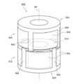
- Fig. 1 is a perspective view of a rotor unit.
- Fig. 2 is a longitudinal cross-sectional view of a motor.
- Fig. 3 is a perspective view of a first rotating body.
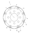
- Fig. 4 is a top view of the first rotating body.
- Fig. 5 is a perspective view of the first rotating body and a second rotating body.
- Fig. 6 is a partial side view of the first rotating body and the second rotating body.
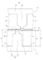
- Fig. 7 is a partial longitudinal cross-sectional view of the rotor unit.
- Fig. 8 is a flowchart showing manufacturing procedure of the rotor unit.
- Fig. 9 is a side view of a first rotating body, a second rotating body, and a central rotating body.
- Fig. 10 is a partial side view of the first rotating body, the second rotating body, and the central rotating body.
- each section will be described with each of the surfaces facing each other of a first rotating body and a second rotating body set to be a "top surface” and each of the surfaces which are turned away from each other set to be a "bottom surface”.
- these terms are those defined only for the convenience of explanation. These terms are not intended to limit the positions in use of a rotor unit and a rotating electrical machine which are related to the invention.
- Fig. 1 is a perspective view of a rotor unit 32A for a rotating electrical machine related to an embodiment of the invention.
- the rotor unit 32A includes two rotating bodies 41A and 42A.
- the two rotating bodies 41A and 42A are arranged along a central axis 9A.
- some hidden lines of the rotating body 41A are shown by dashed lines.
- Each of the two rotating bodies 41A and 42A has a rotor core 51A, a holder 52A, and a plurality of magnets 53A.
- the rotor core 51A is an annular member surrounding the central axis 9A.
- the plurality of magnets 53A is arranged in the circumferential direction around the rotor core 51A and held by the holder 52A.
- the holder 52A has a plurality of partitioning portions 60A each axially extending between the magnets 53A. As shown in Fig. 1, the axial dimension of each partitioning portion 60A is made longer than the axial dimension of the magnet 53A which is held by the partitioning portions 60A.
- the two rotating bodies 41A and 42A are disposed in a state where the circumferential positions of the plurality of magnets 53A are out of alignment. For this reason, the partitioning portion 60A restricts the axial movement of the magnet 53A. In this way, contact between the magnet 53A of the rotating body 41A on one side and the magnet 53A of the rotating body 42A on the other side is prevented. Therefore, damage to each magnet 53A is suppressed.
- the rotor core 51A is disposed inside a mold. Then, resin is injected into the inside of the mold. In this way, the holder 52A is insert-molded into a shape having the plurality of partitioning portions 60A.
- the holder 52A is molded such that the axial dimension of the partitioning portion 60A becomes longer than the axial dimension of the magnet 53A.
- both the molding of the holder 52A and the fixing of the rotor core 51A to the holder 52A are performed. For this reason, the process of manufacturing the rotor core 51A and the holder 52A is shortened.
- the magnet 53A is disposed between a pair of adjacent partitioning portions 60A. If insert molding is attempted including even the magnets, before the insert molding, it is necessary to fix the magnets to the rotor core at least once by adhesion or the like. In contrast to this, in this embodiment, the magnets 53A are positioned by using the holder 52A after molding is completed and hardening is then performed. For this reason, compared to the case of performing insert molding including even the magnets 53A, the plurality of magnets 53A can be easily and accurately positioned.
- the two rotating bodies 41A and 42A fabricated by the above process are arranged in the axial direction.
- the plurality of rotating bodies 41A and 42A is arranged in a state where the circumferential positions of the plurality of magnets 53A are out of alignment.
- Fig. 2 is a longitudinal cross-sectional view of a motor 1 that is one example of a rotating electrical machine.
- the motor 1 related to this embodiment is mounted on an automobile and generates the driving force of a power steering.
- the motor 1 includes a stationary section 2 and a rotating section 3.
- the rotating section 3 is supported so as to be able to rotate with respect to the stationary section 2.
- the stationary section 2 in this embodiment includes a housing 21, a lid section 22, an armature 23, a lower bearing section 24, and an upper bearing section 25.
- the housing 21 is a bottomed and approximately cylindrical case which accommodates the armature 23, the lower bearing section 24, and the rotating section 3 in the inside thereof.
- a concave portion 211 for retaining the lower bearing section 24 is formed.
- the lid section 22 is a plate-like member which blocks an opening of an upper portion of the housing 21.
- a circular hole 221 for retaining the upper bearing section 25 is formed.
- the armature 23 generates magnetic flux depending on a driving current.
- the armature 23 includes a stator core 26 and a coil 27.
- the stator core 26 is composed of laminated steel plates in which a plurality of steel plates is laminated in the axial direction (a direction along a central axis 9, hereinafter the same).
- the stator core 26 includes an annular core back 261 and a plurality of tooth portions 262 protruding from the core back 261 toward the inside in the radial direction (a direction perpendicular to the central axis 9, hereinafter the same).
- the core back 261 is fixed to the inner circumferential surface of a side wall of the housing 21.
- the coil 27 is constituted by a conducting wire wound on each tooth portion 262 of the stator core 26.
- the lower bearing section 24 and the upper bearing section 25 are mechanisms which rotatably support a shaft 31 on the rotating section 3 side.
- a ball bearing in which an outer race and an inner race are relatively rotated through a spherical body is used.
- another type of bearing such as a plain bearing or a fluid bearing may also be used.
- An outer race 241 of the lower bearing section 24 is fixed to the concave portion 211 of the housing 21. Further, an outer race 251 of the upper bearing section 25 is fixed to an edge of the circular hole 221 of the lid section 22.
- inner races 242 and 252 of the lower bearing section 24 and the upper bearing section 25 are fixed to the shaft 31. For this reason, the shaft 31 is supported so as to be able to rotate with respect to the housing 21 and the lid section 22.
- the rotating section 3 in this embodiment includes the shaft 31 and a rotor unit 32.
- the shaft 31 is an approximately columnar member extending in the up-and-down direction along the central axis 9.
- the shaft 31 rotates around the central axis 9 while being supported on the lower bearing section 24 and the upper bearing section 25 described above.
- the shaft 31 has a head portion 311 protruding above the lid section 22.
- the head portion 311 is connected to a steering gear of an automobile through a power transmission mechanism such as a gear.
- the rotor unit 32 is a unit which rotates along with the shaft 31 radially inside the armature 23.
- the rotor unit 32 includes a first rotating body 41, a second rotating body 42, and a cover 43.
- Each of the first rotating body 41 and the second rotating body 42 in this embodiment includes a rotor core 51, a magnet holder 52, and a plurality of magnets 53.
- the first rotating body 41 and the second rotating body 42 are arranged along the central axis 9 in a state where the top surfaces where the magnets 53 are exposed face each other and the bottom surfaces that are other end surfaces are turned away from each other.
- the cover 43 is an approximately cylindrical member which retains the rotor unit 32.
- the cover 43 covers the outer circumferential and a portion of each of both axial end surfaces of the rotor unit 32. In this way, the first rotating body 41 and the second rotating body 42 are maintained in the state of coming into contact with each other.
- the motor 1 if a driving current is imparted to the coil 27 of the stationary section 2, radial magnetic flux is generated in the plurality of tooth portions 262 of the stator core 26. Then, circumferential torque is generated by the action of the magnetic flux between each tooth portion 262 and each magnet 53. As a result, the rotating section 3 rotates around the central axis 9 with respect to the stationary section 2. If the rotating section 3 rotates, a driving force is transmitted to the steering gear connected to the shaft 31.
- the rotor unit 32 in this embodiment includes the first rotating body 41, the second rotating body 42, and the cover 43.
- first, the structures of the first rotating body 41 and the second rotating body 42 will be described.
- Fig. 3 is a perspective view of the first rotating body 41.
- Fig. 4 is a diagram showing the first rotating body 41 when viewed from the top surface side. As shown in Figs. 3 and 4, the first rotating body 41 includes the rotor core 51, the magnet holder 52, and the plurality of magnets 53.
- the rotor core 51 is an annular member surrounding the central axis 9. At the center of the rotor core 51, a through-hole 511 into which the shaft 31 is inserted is provided.
- the rotor core 51 is composed of laminated steel plates in which electromagnetic steel plates are laminated in the axial direction.
- the rotor core 51 in this embodiment has an outer circumferential surface of an approximately regular polygonal column shape. In the outer circumferential surface of the rotor core 51, a plurality of groove portions 512 extending in the axial direction is provided. Each groove portion 512 is radially inwardly recessed at a boundary portion between the flat surfaces constituting the outer circumferential surface of the rotor core 51.
- the magnet holder 52 is a member made of resin, which holds the magnets 53.
- the magnet holder 52 has a plurality of partitioning portions 60 and an annular connection portion 70 which connects end portions on the bottom surface side of the plurality of partitioning portions 60.
- the plurality of partitioning portions 60 is arranged at approximately regular intervals in the circumferential direction. Each partitioning portion 60 axially extends along the side surface of the rotor core 51 in the vicinity of the groove portion 512 of the rotor core 51.
- the partitioning portion 60 has an inner columnar portion 61 and an outer columnar portion 62.
- the inner columnar portion 61 axially extends in the groove portion 512, that is, further at the inside in the radial direction than the outer circumferential surface of the rotor core 51.
- an end portion on the top surface side of the inner columnar portion 61 is disposed at an axial position approximately equal to the top surface of the rotor core 51.
- the outer columnar portion 62 axially extends further at the outside in the radial direction than the outer circumferential surface of the rotor core 51.
- a convex portion 63 protruding further to the second rotating body 42 side than the top surface of the rotor core 51 is provided.
- the plurality of magnets 53 is arranged around the rotor core 51.
- Each magnet 53 has an approximately flat plate-like outer shape and is press-fitted between a pair of adjacent partitioning portions 60. An end portion on the bottom surface side of the magnet 53 comes into contact with the connection portion 70 of the magnet holder 52. That is, the connection portion 70 of the magnet holder 52 has a contact surface 71 which comes into contact with the end portion on the bottom surface side of the magnet 53.
- the radially outer surface of the magnet 53 becomes a magnetic pole face which faces the armature 23.
- the plurality of magnets 53 is disposed at regular intervals in the circumferential direction in such a manner that an N-pole magnetic pole face and an S-pole magnetic pole face are alternately arranged.
- an Nd-Fe-B alloy-based sintered magnet can be used as the magnet 53.
- the second rotating body 42 in this embodiment is disposed in a state where the top surface and the bottom surface are inverted.
- a structure itself is approximately the same as that of the first rotating body 41. That is, the second rotating body 42 includes the rotor core 51, the magnet holder 52, and the plurality of magnets 53 which are the same as those of the first rotating body 41. With respect to the details of each section of the second rotating body 42, overlapping explanation will be omitted.
- Fig. 5 is a perspective view of the first rotating body 41 and the second rotating body 42 which are disposed inside the cover 43.
- the first rotating body 41 and the second rotating body 42 are axially arranged in a state where the top surfaces face each other and the bottom surfaces are turned away from each other. Further, the first rotating body 41 and the second rotating body 42 are arranged in a state where the circumferential positions of the plurality of magnets 53 are out of alignment. In this manner, by making the circumferential positions of the plurality of magnets 53 be out of alignment, cogging or torque ripple of the motor 1 is reduced.
- the end portion on the top surface side of the inner columnar portion 61 is disposed at an axial position approximately equal to the top surface of the rotor core 51.
- the convex portion 63 (refer to Fig. 3) is provided at a position further to the outside in the radial direction than the outer circumferential surface of the rotor core 51.
- the circumferential positions of the first rotating body 41 and the second rotating body 42 can be made to be out of alignment while bringing the rotor cores 51 into contact with each other.
- the end portion on the top surface side of the inner columnar portion 61 may also be located further to the bottom surface side than the top surface of the rotor core 51.
- Fig. 6 is a partial side view of the first rotating body 41 and the second rotating body 42.
- the axial dimension d1 from the contact surface 71 of the connection portion 70 to an end portion on the top surface side of the convex portion 63 is longer than the axial dimension d2 of the magnet 53.
- the convex portion 63 of the partitioning portion 60 restricts axial movement of the magnet 53. In this way, contact between the magnets 53 is prevented. Therefore, damage to the magnet 53 can be suppressed.
- the rotor core 51 in this embodiment has an outer shape of an approximately regular polygonal column shape. Then, the rotor cores 51 of the two rotating bodies 41 and 42 are disposed in a state where the circumferential positions thereof are out of alignment. For this reason, corner portions of the rotor core 51 of the rotating body on one side protrude to the outside in the radial direction of the rotor core 51 on the other side and axially face the magnets 53 of the rotating body on the other side. Therefore, if axial movement of the magnet 53 is not restricted, contact between the corner portion of the rotor core 51 and the magnet 53 can occur.
- the convex portions 63 of each rotating body protrude further to the other rotating body side than the top surface of the rotor core 51. That is, the axial dimension d1 from the contact surface 71 to the end portion on the top surface side of the convex portion 63 is longer than the axial dimension d3 from the contact surface 71 to the top surface of the rotor core 51. Further, the axial dimension d2 of the magnet 53 is shorter than the axial dimension d3 from the contact surface 71 to the top surface of the rotor core 51.
- the partitioning portion 60 in this embodiment prevents not only contact between the magnets 53, but also contact between the rotor core 51 and the magnet 53. In this way, damage to the magnet 53 is further suppressed.
- the axial dimension d3 from the contact surface 71 to the top surface of the rotor core 51 is larger than the sum of the axial dimension d2 of the magnet 53 and the axial dimension d4 from the top surface of the rotor core 51 to the end portion on the top surface side of the convex portion 63. For this reason, a clearance is provided between the magnet 53 of the rotating body on one side and the convex portion 63 of the rotating body on the other side. Through this clearance, dimensional errors of each member can be absorbed.
- the rotor core 51 in this embodiment is composed of laminated steel plates.
- the axial dimension of the rotor core 51 is prone to varying. Therefore, approach of the magnets 53 to each other or approach of the rotor core 51 to the magnet 53 is prone to occurring.
- contact between the magnets 53 and contact between the rotor core 51 and the magnet 53 can be prevented.
- the cover 43 is made of a nonmagnetic metal such as iron or aluminum.
- the cover 43 is formed by, for example, press working or the like.
- Fig. 7 is a partial longitudinal cross-sectional view of the rotor unit 32. As shown in Fig. 7, the cover 43 has a cylindrical portion 431, a first annular swaged portion 432, and a second annular swaged portion 433.
- the cylindrical portion 431 surrounds the outer circumferential surfaces of the first rotating body 41 and the second rotating body 42.
- the cover 43 is not limited to nonmagnetic metal and may also be formed of nonmagnetic resin or the like.
- the first annular swaged portion 432 is an annular site folded radially inward along the bottom surface of the first rotating body 41.
- the first annular swaged portion 432 comes into contact with the bottom surface of the magnet holder 52 of the first rotating body 41.
- a plurality of cutouts 72 and 73 shown in Fig. 5 is provided in the bottom surface of the connection portion 70.
- a radially inner end portion of the first annular swaged portion 432 is further swaged so as to be fitted into the cutouts 72 and 73. In this way, relative circumferential rotation around the central axis 9 of the first rotating body 41 and the cover 43 is prevented.
- the plurality of cutouts 72 and 73 is provided at circumferential positions corresponding to the plurality of magnets 53, as shown in Fig. 5.
- the plurality of cutouts 72 and 73 in this embodiment include a rectangular cutout 72 and a semicircular cutout 73 and the cutouts 72 and 73 distinguishable in appearance are arranged alternately in the circumferential direction. Even after the cover 43 is attached, the cutouts 72 and 73 are visible from the outside of the rotor unit 32. Therefore, the positions of an N pole and an S pole of the rotor unit 32 can be confirmed on the basis of the cutouts 72 and 73.
- the second annular swaged portion 433 is folded radially inward along an edge of the bottom surface on the second rotating body 42 side.
- the second annular swaged portion 433 comes into contact with the bottom surface of the magnet holder 52 of the second rotating body 42.
- the radial dimension of the second annular swaged portion 433 is smaller than the radial dimension of the first annular swaged portion 432. In this way, occurrence of wrinkles in the second annular swaged portion 433 is suppressed.
- the first rotating body 41 and the second rotating body 42 are sandwiched in between the first annular swaged portion 432 and the second annular swaged portion 433 in a state where the first rotating body 41 and the second rotating body 42 respectively come into contact with the first annular swaged portion 432 and the second annular swaged portion 433. In this way, the first rotating body 41 and the second rotating body 42 are held in the state of coming into contact with each other. In this manner, the cover 43 in this embodiment easily and reliably fixes the first rotating body 41 and the second rotating body 42 by swaging both end portions.
- the structure of the cover 43 can be widely applied to fixing of a plurality of rotating bodies arranged axially, without being limited to the first rotating body 41 and the second rotating body 42 in this embodiment.
- Step S1 When manufacturing the rotor unit 32, first, a pair of molds and the prefabricated rotor core 51 are prepared (Step S1).
- the rotor core 51 is fabricated by axially laminating punching-worked steel plates, for example.
- the pair of molds forms a cavity corresponding to the shapes of the rotor core 51 and the magnet holder 52 in the inside thereof by bringing the opposed surfaces thereof into contact with each other.
- Step S2 the rotor core 51 is disposed inside the pair of molds.
- the rotor core 51 is disposed inside the mold on one side. Then, an upper portion of the above mold is blocked by the mold on the other side. In this way, a state is created where a cavity is formed inside the molds and the rotor core 51 is disposed in the cavity.
- Step S3 resin in a fluidized state is injected into the cavity formed inside the molds.
- resin in a fluidized state is injected into the cavity in the mold through a runner provided at the mold.
- Step S4 the resin in the mold is cooled and solidified.
- the resin in the mold is solidified, thereby being turned into the magnet holder 52. Further, the rotor core 51 and the magnet holder 52 are fixed to each other along with the solidification of the resin.
- the magnet holder 52 is molded so as to have the plurality of partitioning portions 60 and the connection portion 70 and satisfy the above-described dimensional relationship in Fig. 6.
- Steps S1 to S5 are procedure which becomes one example of insert molding.
- both the molding of the magnet holder 52 and the fixing of the rotor core 51 to the magnet holder 52 are performed. For this reason, compared to a case where the rotor core 51 and the magnet holder 52 are separately fabricated and fixed to each other, the process of manufacturing the rotor core 51 and the magnet holder 52 can be shortened.
- the rotor core 51 it is preferable to position the rotor core 51 by bringing the top surface of the rotor core 51 into contact with the mold on one side. That is, it is preferable to axially position the rotor core 51 inside the pair of molds with the top surface side as a standard. If the rotor core 51 is positioned with the top surface side as a standard, even if variation is present in the axial dimension of the rotor core 51, the thickness of the connection portion 70 of the magnet holder 52 is increased or decreased depending on the variation. Therefore, the dimensional relationship of d1 to d4 described above can be realized regardless of variation in the axial dimension of the rotor core 51.
- the magnet 53 is prepared and then press-fitted between a pair of adjacent outer columnar portions 62 (Step S6). Then, the bottom surface of the magnet 53 is brought into contact with the contact surface 71 of the connection portion 70. The axial and circumferential positions of the magnet 53 are determined by the contact surface 71 and the outer columnar portion 62 of the magnet holder 52.
- the structure of the mold is complicated in order to perform positioning of the magnets with respect to the rotor core. Or, it is necessary to fix the magnets to the rotor core once by adhesion or the like before insert molding.
- the magnet 53 is positioned by using the magnet holder 52 after the insert molding is completed and solidification is performed. For this reason, it is possible to easily and accurately position a plurality of magnets 53.
- Each of the first rotating body 41 and the second rotating body 42 is fabricated by the above Steps S1 to S6.
- the magnet holder 52 of the first rotating body 41 and the magnet holder 52 of the second rotating body 42 have approximately the same shape. For this reason, during the insert molding, it is possible to fabricate the magnet holder 52 of each of the rotating bodies 41 and 42 by using the same mold.
- Step S7 the first rotating body 41 and the second rotating body 42 are arranged axially.
- the first rotating body 41 and the second rotating body 42 are arranged in a state where the top surfaces of both the rotating bodies 41 and 42 face each other, the bottom surfaces of both the rotating bodies 41 and 42 are turned away from each other, and the circumferential positions of the plurality of magnets 53 are out of alignment.
- the cover 43 is attached to the first rotating body 41 and the second rotating body 42 (Step S8).
- both end portions of the cover 43 are swaged, thereby forming the first swaged portion 432 and the second swaged portion 433.
- the first rotating body 41 and the second rotating body 42 are fixed to each other in the state of coming into contact with each other.
- Fig. 9 is a side view of a rotor unit 32B related to another embodiment.
- illustration of the cover is omitted.
- the rotor unit 32B includes a first rotating body 41B, a second rotating body 42B, and a central rotating body 44B.
- each of the first rotating body 41B and the second rotating body 42B includes a rotor core 51B, a magnet holder 52B, and a plurality of magnets 53B, which are similar to those in the above-described embodiment. With respect to the details of each section, overlapping explanation will be omitted.
- the central rotating body 44B includes a central rotor core 54B, a central magnet holder 55B, and a plurality of central magnets 56B.
- a central rotor core 54B in this embodiment, a rotor core similar to the rotor core 51B of each of the first rotating body 41B and the second rotating body 42B is used.
- the central rotor core 54B is fixed to a shaft between a pair of rotor cores 51B.
- central magnet 56B in this embodiment, a magnet similar to the magnet 53B of each of the first rotating body 41B and the second rotating body 42B is used.
- the plurality of central magnets 56B is arranged at regular intervals around the central rotor core 54B.
- the number of central magnets 56B that the central rotating body 44B has is made to be the same as the number of magnets 53B that each of the first rotating body 41B and the second rotating body 42B has.
- the central magnet holder 55B is a member made of resin, which holds the central magnets 56B.
- the central magnet holder 55B is different from the magnet holders 52B of the first rotating body 41B and the second rotating body 42B in that the central magnet holder 55B has no connection portion 70B.
- the central magnet holder 55B has a plurality of central partitioning portions 90B. Each central partitioning portion 90B axially extends between the central magnets 56B adjacent to each other.
- a first convex portion 93B is provided at an end portion on the first rotating body 41B side of each central partitioning portion 90B.
- the first convex portion 93B protrudes further to the first rotating body 41B side than an end portion on the first rotating body 41B side of the central rotor core 54B.
- a second convex portion 94B is provided at an end portion on the second rotating body 42B side of each central partitioning portion 90B.
- the second convex portion 94B protrudes further to the second rotating body 42B side than an end portion on the second rotating body 42B side of the central rotor core 54B.
- the first rotating body 41B and the second rotating body 42B are axially arranged in a state where the top surfaces face each other and the bottom surfaces are turned away from each other.
- the central rotating body 44B is disposed between the first rotating body 41B and the second rotating body 42B.
- the first rotating body 41B, the central rotating body 44B, and the second rotating body 42B are arranged in a state where the circumferential positions of the plurality of magnets 53B and 56B are out of alignment. In this manner, by making the circumferential positions of the plurality of magnets 53B and 56B be out of alignment, cogging or torque ripple of a motor is reduced.
- Fig. 10 is a partial side view of the first rotating body 41B, the second rotating body 42B, and the central rotating body 44B.
- the axial dimension d5 of the central partitioning portion 90B that is, the axial dimension d5 from an end portion on the first rotating body 41B side of the first convex portion 93B to an end portion on the second rotating body 42B side of the second convex portion 94B is longer than the axial dimension d6 of the central rotor core 54B.
- the axial dimension d7 of the central magnet 56B is shorter than the axial dimension d6 of the central rotor core 54B.
- the central magnet 56B is disposed between a convex portion 63B provided at a partitioning portion 60B of the first rotating body 41B and a convex portion 63B provided at a partitioning portion 60B of the second rotating body 42B.
- the axial dimension d8 from a contact surface 71B to an end portion on the top surface side of the convex portion 63B is longer than the axial dimension d9 from the contact surface 71B to the top surface of the rotor core 51B.
- the axial dimension d10 of the magnet 53B is shorter than the axial dimension d9 from the contact surface 71B to the top surface of the rotor core 51B. Then, the magnet 53B is disposed between the contact surface 71B and the first convex portion 93B or the second convex portion 94B provided at the central partitioning portion 90B.
- a clearance is provided between the first convex portion 93B and the top surface of the magnet 53B of the first rotating body 41B.
- dimensional errors of each member are allowed.
- the end surface of the magnet 53B comes into contact with the first convex portion 93B.
- the first convex portion 93B of the central partitioning portions 90B restricts axial movement of the magnet 53B of the first rotating body 41B. In this way, damage to the magnet 53B is suppressed.
- the second convex portion 94B comes into contact with the top surface of the magnet 53B of the second rotating body 42B. That is, in this embodiment, the magnet 53B of the second rotating body 42B comes into contact with both the contact surface 71B of the second rotating body 42B and the second convex portion 94B. In this way, the shift itself of the axial position of the magnet 53B of the second rotating body 42B is prevented.
- the central rotating body 44B is fabricated by a manufacturing method based on the method of manufacturing the first rotating body 41B or the second rotating body 42B in the above-described embodiment.
- the central magnet holder 55B is insert-molded after the central rotor core 54B is disposed inside a mold.
- the end surface on the first rotating body 41B side of the central rotor core 54B is brought into contact with a mold on one side. That is, the central rotor core 54B is axially positioned inside a pair of molds with the end surface on the first rotating body 41B side as a standard. If doing so, it is possible to make the first convex portion 93B protrude from the end surface on the first rotating body 41B side of the central rotor core 54B regardless of variation in the axial dimension of the central rotor core 54B.
- the central rotor core 54B is positioned with the end surface on the first rotating body 41B side as a standard, a positional relationship between the end surface on the second rotating body 42B side of the central rotor core 54B and the end portion on the second rotating body 42B side of the second convex portion 94B is varied by variation in the axial dimension of the central rotor core 54B.
- the second convex portion 94B is molded longer than the first convex portion 93B such that the second convex portion 94B necessarily protrudes from the end surface on the second rotating body 42B side of the central rotor core 54B.
- the dimensions of the central rotor core 54B and the central magnet holder 55B are set such that the end surface on the second rotating body 42B side of the central rotor core 54B is disposed further to the second rotating body 42B side than a base end portion of the second convex portion 94B regardless of variation in the axial dimension of the central rotor core 54B. In this way, the end surface on the second rotating body 42B side of the central rotor core 54B and the top surface of the rotor core 51B of the second rotating body 42B are made to come into contact with each other.
- the outer circumferential surface of the rotor core may also be a polygonal column shape as described above, and as another example, a cylindrical shape is also acceptable. Further, the number of partitioning portions of the magnet holder or the number of magnets may also be a number different from that in the above-described embodiments.
- the partitioning portion may also wholly protrude further to the rotating body side on the other side than the top surface of the rotor core without having the convex portion as described above.
- the magnet holder may also be fabricated by insert molding, as described above, and may also be independently molded separately from the rotor core.
- the plurality of rotating bodies related to the embodiments of the invention may also have structures different from each other, and the rotor unit according to the invention may also have four or more of the rotating bodies.
- the central rotating bodies may also be disposed between the first rotating body and the second rotating body.
- the rotating electrical machine according to the invention may also be a motor for power steering as described above and may also be a motor which is used in another site of an automobile.
- the rotating electrical machine according to the invention may also be a motor for generating the driving force of the electric automobile.
- the rotating electrical machine according to the invention may also be a motor which is used in an electric power-assisted bicycle, an electric motorcycle, home electric appliances, office equipment, medical equipment, or the like.
- the rotating electrical machine according to the invention may also be an electric generator which is used in an automobile, an electric power-assisted bicycle, wind-power generation, or the like.
- the invention can be used in a rotor unit, a rotating electrical machine, and a method of manufacturing a rotor unit.
Landscapes
- Engineering & Computer Science (AREA)
- Power Engineering (AREA)
- Manufacturing & Machinery (AREA)
- Chemical & Material Sciences (AREA)
- Combustion & Propulsion (AREA)
- Transportation (AREA)
- Mechanical Engineering (AREA)
- Permanent Field Magnets Of Synchronous Machinery (AREA)
- Manufacture Of Motors, Generators (AREA)
Abstract
Description
The above and other elements, features, steps, characteristics and advantages of the present invention will become more apparent from the following detailed description of the preferred embodiments of the present invention with reference to the attached drawings.
As shown in Fig. 1, the
While preferred embodiments of the present invention have been described above, it is to be understood that variations and modifications will be apparent to those skilled in the art without departing from the scope and spirit of the present invention. The scope of the present invention, therefore, is to be determined solely by the following claims.
2: stationary section
3: rotating section
9, 9A: central axis
21: housing
22: lid section
23: armature
24: lower bearing section
25: upper bearing section
26: stator core
27: coil
31: shaft
32, 32A, 32B: rotor unit
41, 41A, 41B: first rotating body
42, 42A, 42B: second rotating body
43: cover
44B: central rotating body
51, 51A, 51B: rotor core
52, 52B: magnet holder
52A: holder
53, 53A, 53B: magnet
54B: central rotor core
55B: central magnet holder
56B: central magnet
60, 60A, 60B: partitioning portion
61: inner columnar portion
62: outer columnar portion
63, 63B: convex portion
70: connection portion
71, 71B: contact surface
90B: central partitioning portion
93B: first convex portion
94B: second convex portion
431: cylindrical portion
432: first annular swaged portion
433: second annular swaged portion
Claims (15)
- A rotor unit for a rotating electrical machine, comprising:
a plurality of rotating bodies which is arranged along a central axis,
wherein each of the plurality of rotating bodies includes:
an annular rotor core which surrounds the central axis,
a plurality of magnets which is arranged in a circumferential direction around the rotor core, and
a holder which holds the magnets,
the holder has a plurality of partitioning portions each axially extending between the magnets,
the axial dimension of the partitioning portion is longer than the axial dimension of the magnet which is held by the partitioning portions, and
the plurality of rotating bodies is disposed in a state where the circumferential positions of the plurality of magnets are out of alignment. - The rotor unit according to Claim 1, wherein the plurality of rotating bodies include a first rotating body and a second rotating body which are arranged along the central axis in a state where the top surfaces face each other and the bottom surfaces are turned away from each other,
a holder of each of the first rotating body and the second rotating body further has a connection portion which connects the plurality of partitioning portions,
the connection portion has a contact surface which comes into contact with an end portion on the bottom surface side of the magnet, and
an axial dimension from the contact surface to an end portion on the top surface side of the partitioning portion is longer than the axial dimension of the magnet. - The rotor unit according to Claim 2, wherein an axial dimension from the contact surface to an end portion on the top surface side of the rotor core is shorter than the axial dimension from the contact surface to the end portion on the top surface side of the partitioning portion and longer than the axial dimension of the magnet.
- The rotor unit according to Claim 3, wherein the rotor core has an outer circumferential surface of a regular polygonal column shape.
- The rotor unit according to Claim 3 or 4, wherein the partitioning portion has:
an inner columnar portion which is located further to the inside in a radial direction than the outer circumferential surface of the rotor core, and
an outer columnar portion which is located further to the outside in a radial direction than the outer circumferential surface of the rotor core,
an end portion on the top surface side of the inner columnar portion is disposed at an axial position which is equal to or further to the bottom surface side than the end portion on the top surface side of the rotor core, and
an end portion on the top surface side of the outer columnar portion is disposed further to the top surface side than the end portion on the top surface side of the rotor core. - The rotor unit according to any one of Claims 2 to 5, wherein the axial dimension from the contact surface to the end portion on the top surface side of the rotor core is larger than the sum of an axial dimension from the end portion on the top surface side of the rotor core to the end portion on the top surface side of the partitioning portion and the axial dimension of the magnet.
- The rotor unit according to any one of Claims 2 to 6, wherein the partitioning portion has a convex portion provided at an end portion thereof on the top surface side.
- The rotor unit according to any one of Claims 2 to 7, wherein the holder of the first rotating body and the holder of the second rotating body have the same shape as each other.
- The rotor unit according to any one of Claims 2 to 8, wherein the holder is a resin member, and
the holder is formed on the surface of the rotor core by insert molding. - The rotor unit according to any one of Claims 2 to 9, wherein the plurality of rotating bodies further includes a central rotating body which is disposed between the first rotating body and the second rotating body,
a magnet of the first rotating body is disposed between a contact surface of the first rotating body and a partitioning portion of the central rotating body,
a magnet of the central rotating body is disposed between a partitioning portion of the first rotating body and a partitioning portion of the second rotating body, and
a magnet of the second rotating body is disposed between a contact surface of the second rotating body and the partitioning portion of the central rotating body. - The rotor unit according to Claim 10, wherein the partitioning portion of the central rotating body has:
a first convex portion provided at an end portion thereof on the first rotating body side, and
a second convex portion provided at an end portion thereof on the second rotating body side. - The rotor unit according to Claim 11, wherein the first convex portion protrudes further to the first rotating body side than an end portion on the first rotating body side of a rotor core of the central rotating body,
the second convex portion protrudes further to the second rotating body side than an end portion on the second rotating body side of the rotor core of the central rotating body, and
the magnet of the second rotating body comes into contact with both the contact surface of the second rotating body and the second convex portion. - The rotor unit according to Claim 12, wherein the end portion on the second rotating body side of the rotor core of the central rotating body is disposed further to the second rotating body side than a base end portion of the second convex portion.
- A rotating electrical machine comprising:
a stationary section; and
a rotating section which is supported so as to be able to rotate with respect to the stationary section,
wherein the rotating section has:
the rotor unit according to any one of Claims 1 to 13, and
a shaft inserted inside the rotor core, and
the stationary section has:
bearing sections which rotatably support the shaft, and
an armature disposed on the outside in a radial direction of the rotor unit. - A method of manufacturing a rotor unit for a rotating electrical machine, which includes a plurality of rotating bodies each having an annular rotor core that surrounds a central axis, a plurality of magnets that is arranged in a circumferential direction around the rotor core, and a holder made of resin, that holds the magnets, the method comprising:
(a) a process of insert-molding the holder into a shape having a plurality of partitioning portions axially extending along the outer circumferential surface of the rotor core, by disposing the rotor core inside a mold and injecting resin into the inside of the mold;
(b) a process of disposing the magnet between a pair of adjacent partitioning portions after the process (a); and
(c) a process of axially arranging the plurality of rotating bodies fabricated by the processes (a) and (b),
wherein in the process (a), the holder is molded such that the axial dimension of the partitioning portion becomes longer than the axial dimension of the magnet, and
in the process (c), the plurality of rotating bodies is arranged in a state where the circumferential positions of the plurality of magnets are out of alignment.
Priority Applications (5)
| Application Number | Priority Date | Filing Date | Title |
|---|---|---|---|
| BR112013021483A BR112013021483A2 (en) | 2011-04-02 | 2012-04-02 | rotor unit, rotary electric machine and method of manufacturing rotor unit |
| DE112012001550.9T DE112012001550B4 (en) | 2011-04-02 | 2012-04-02 | Rotor unit, rotating electrical machine and method for producing a rotor unit |
| CN201280004127.XA CN103339830B (en) | 2011-04-02 | 2012-04-02 | Rotor unit, rotating electric machine and method of manufacturing rotor unit |
| US13/991,908 US9257874B2 (en) | 2011-04-02 | 2012-04-02 | Rotor unit, rotating electrical machine, and method of manufacturing rotor unit |
| KR1020137020009A KR101663552B1 (en) | 2011-04-02 | 2012-04-02 | Rotor unit, rotating electrical machine, and method of manufacturing rotor unit |
Applications Claiming Priority (2)
| Application Number | Priority Date | Filing Date | Title |
|---|---|---|---|
| JP2011-082323 | 2011-04-02 | ||
| JP2011082323A JP5720939B2 (en) | 2011-04-02 | 2011-04-02 | Rotor unit, rotating electric machine, and method of manufacturing rotor unit |
Publications (1)
| Publication Number | Publication Date |
|---|---|
| WO2012137465A1 true WO2012137465A1 (en) | 2012-10-11 |
Family
ID=46968876
Family Applications (1)
| Application Number | Title | Priority Date | Filing Date |
|---|---|---|---|
| PCT/JP2012/002274 Ceased WO2012137465A1 (en) | 2011-04-02 | 2012-04-02 | Rotor unit, rotating electrical machine, and method of manufacturing rotor unit |
Country Status (7)
| Country | Link |
|---|---|
| US (1) | US9257874B2 (en) |
| JP (1) | JP5720939B2 (en) |
| KR (1) | KR101663552B1 (en) |
| CN (2) | CN103339830B (en) |
| BR (1) | BR112013021483A2 (en) |
| DE (1) | DE112012001550B4 (en) |
| WO (1) | WO2012137465A1 (en) |
Cited By (1)
| Publication number | Priority date | Publication date | Assignee | Title |
|---|---|---|---|---|
| EP2876789A3 (en) * | 2013-11-20 | 2016-02-17 | Brose Fahrzeugteile GmbH & Co. Kommanditgesellschaft, Würzburg | Method for manufacturing a rotor |
Families Citing this family (32)
| Publication number | Priority date | Publication date | Assignee | Title |
|---|---|---|---|---|
| JP6008228B2 (en) * | 2011-12-26 | 2016-10-19 | 日本電産株式会社 | motor |
| JP6220544B2 (en) * | 2013-04-18 | 2017-10-25 | 日立オートモティブシステムズ株式会社 | motor |
| WO2015118682A1 (en) * | 2014-02-10 | 2015-08-13 | 三菱電機株式会社 | Rotor |
| US10742082B2 (en) * | 2014-12-31 | 2020-08-11 | Ingersoll-Rand Industrial U.S., Inc. | Fixation system for a permanent magnet rotor |
| KR102544529B1 (en) | 2016-03-02 | 2023-06-16 | 엘지이노텍 주식회사 | Rotor and motor having the same |
| KR102625594B1 (en) | 2016-03-02 | 2024-01-16 | 엘지이노텍 주식회사 | Rotor and motor having the same |
| US10910896B2 (en) | 2016-03-02 | 2021-02-02 | Lg Innotek Co., Ltd. | Rotor and motor comprising same |
| CN109792177A (en) * | 2016-09-29 | 2019-05-21 | 日本电产株式会社 | Rotor unit and motor |
| CN207504726U (en) * | 2017-07-21 | 2018-06-15 | 深圳市配天电机技术有限公司 | Electric vehicles, wheels, switched reluctance motors and their current detection circuits |
| CN109428413B (en) * | 2017-08-22 | 2020-11-06 | 西门子公司 | Magnetic steel fixing device, inclined pole rotor and assembling method thereof |
| KR102626024B1 (en) * | 2018-10-02 | 2024-01-18 | 엘지이노텍 주식회사 | Motor |
| CN111373634B (en) * | 2017-11-30 | 2023-04-04 | Lg伊诺特有限公司 | Rotor and motor comprising same |
| KR102510261B1 (en) * | 2017-11-30 | 2023-03-15 | 엘지이노텍 주식회사 | Rotor and motor having the same |
| CN108173364A (en) * | 2018-01-29 | 2018-06-15 | 珠海格力节能环保制冷技术研究中心有限公司 | Rotor structure and with its magneto |
| DE102018105249A1 (en) | 2018-03-07 | 2019-09-12 | Nidec Corporation | Rotor unit and electric motor |
| DE202018006077U1 (en) * | 2018-03-07 | 2019-02-20 | Nidec Corporation | Rotor unit and electric motor |
| JP7080704B2 (en) * | 2018-04-16 | 2022-06-06 | 株式会社ミツバ | Rotor, motor and brushless wiper motor |
| CN110535265B (en) | 2018-05-23 | 2022-04-15 | 德昌电机(深圳)有限公司 | Motor rotor |
| CN108711974A (en) * | 2018-05-28 | 2018-10-26 | 宁波德昌科技有限公司 | A kind of rotor for permanent magnetic brushless |
| JP2020022328A (en) * | 2018-08-03 | 2020-02-06 | 日本電産株式会社 | Rotor and motor |
| KR102626459B1 (en) | 2018-09-03 | 2024-01-18 | 엘지이노텍 주식회사 | Motor |
| CN112703662A (en) * | 2018-09-21 | 2021-04-23 | 三菱电机株式会社 | Rotating electric machine and method for manufacturing same |
| KR102635352B1 (en) * | 2019-01-17 | 2024-02-08 | 엘지이노텍 주식회사 | Rotor and motor having the same |
| DE102019213448A1 (en) * | 2019-09-04 | 2021-03-04 | Volkswagen Aktiengesellschaft | Rotor for an electrical machine with web-shaped holding elements |
| CN114846726B (en) * | 2019-12-23 | 2026-04-24 | Lg伊诺特有限公司 | motor |
| CN113054817B (en) * | 2019-12-27 | 2022-06-14 | 博世电动工具(中国)有限公司 | Electric tool, brushless motor and rotor |
| EP4203251B1 (en) * | 2020-08-20 | 2024-12-04 | Mitsubishi Electric Corporation | Rotor of rotating electric machine and rotating electric machine |
| KR102938742B1 (en) | 2020-09-21 | 2026-03-13 | 엘지이노텍 주식회사 | Motor |
| TWI780639B (en) * | 2021-03-25 | 2022-10-11 | 國立成功大學 | Magnetic gear and magnetic pole part thereof |
| US20240429760A1 (en) | 2021-10-20 | 2024-12-26 | Mitsubishi Electric Corporation | Rotor, rotating electric machine, and electric power steering device |
| DE102023205414A1 (en) * | 2023-06-12 | 2024-12-12 | Brose Fahrzeugteile SE & Co. Kommanditgesellschaft, Würzburg | rotor assembly for an electric motor |
| DE102023206494A1 (en) * | 2023-07-07 | 2023-09-14 | Vitesco Technologies GmbH | Rotor for an electric machine |
Citations (3)
| Publication number | Priority date | Publication date | Assignee | Title |
|---|---|---|---|---|
| EP0569594A1 (en) * | 1991-11-29 | 1993-11-18 | Fanuc Ltd. | Rotor of synchronous rotating machine |
| JP2010141993A (en) * | 2008-12-10 | 2010-06-24 | Mitsuba Corp | Magnet holder for rotary electric machine |
| WO2010090303A1 (en) * | 2009-02-09 | 2010-08-12 | 株式会社ジェイテクト | Electric motor and rotor |
Family Cites Families (11)
| Publication number | Priority date | Publication date | Assignee | Title |
|---|---|---|---|---|
| JPS6464548A (en) * | 1987-09-03 | 1989-03-10 | Fanuc Ltd | Rotor construction of synchronous motor |
| US5397951A (en) | 1991-11-29 | 1995-03-14 | Fanuc Ltd. | Rotor for a synchronous rotary machine |
| JP2001218403A (en) * | 1999-11-26 | 2001-08-10 | Asmo Co Ltd | Rotating magnetic field motor |
| JP4848580B2 (en) * | 2000-07-13 | 2011-12-28 | パナソニック株式会社 | Method for manufacturing permanent magnet motor |
| CN1985424B (en) | 2004-07-16 | 2010-07-07 | 株式会社美姿把 | Magnet fixing structure of rotating electric machine |
| US7157827B2 (en) * | 2004-09-21 | 2007-01-02 | A. O. Smith Corporation | Spoke permanent magnet rotor |
| CN100574052C (en) * | 2006-08-16 | 2009-12-23 | 台达电子工业股份有限公司 | Fan, motor and magnetic shell |
| JP5123008B2 (en) * | 2008-03-05 | 2013-01-16 | 株式会社ミツバ | Brushless motor |
| JP5058849B2 (en) * | 2008-03-05 | 2012-10-24 | 株式会社ミツバ | Brushless motor |
| JP5310109B2 (en) * | 2009-03-03 | 2013-10-09 | 日本精工株式会社 | Brushless motor rotor, brushless motor, electric power steering apparatus, and method for manufacturing brushless motor rotor |
| JP5479008B2 (en) * | 2009-09-18 | 2014-04-23 | 株式会社ミツバ | Brushless motor |
-
2011
- 2011-04-02 JP JP2011082323A patent/JP5720939B2/en active Active
-
2012
- 2012-04-02 KR KR1020137020009A patent/KR101663552B1/en active Active
- 2012-04-02 US US13/991,908 patent/US9257874B2/en active Active
- 2012-04-02 CN CN201280004127.XA patent/CN103339830B/en active Active
- 2012-04-02 WO PCT/JP2012/002274 patent/WO2012137465A1/en not_active Ceased
- 2012-04-02 DE DE112012001550.9T patent/DE112012001550B4/en active Active
- 2012-04-02 CN CN201610143557.XA patent/CN105762956B/en active Active
- 2012-04-02 BR BR112013021483A patent/BR112013021483A2/en active Search and Examination
Patent Citations (3)
| Publication number | Priority date | Publication date | Assignee | Title |
|---|---|---|---|---|
| EP0569594A1 (en) * | 1991-11-29 | 1993-11-18 | Fanuc Ltd. | Rotor of synchronous rotating machine |
| JP2010141993A (en) * | 2008-12-10 | 2010-06-24 | Mitsuba Corp | Magnet holder for rotary electric machine |
| WO2010090303A1 (en) * | 2009-02-09 | 2010-08-12 | 株式会社ジェイテクト | Electric motor and rotor |
Cited By (2)
| Publication number | Priority date | Publication date | Assignee | Title |
|---|---|---|---|---|
| EP2876789A3 (en) * | 2013-11-20 | 2016-02-17 | Brose Fahrzeugteile GmbH & Co. Kommanditgesellschaft, Würzburg | Method for manufacturing a rotor |
| US9673670B2 (en) | 2013-11-20 | 2017-06-06 | Brose Fahrzeugteile Gmbh & Co. Kommanditgesellschaft, Wuerzburg | Method for producing a rotor and electric machine having a rotor |
Also Published As
| Publication number | Publication date |
|---|---|
| DE112012001550B4 (en) | 2024-12-24 |
| KR101663552B1 (en) | 2016-10-07 |
| CN103339830A (en) | 2013-10-02 |
| BR112013021483A2 (en) | 2016-10-11 |
| DE112012001550T5 (en) | 2014-01-02 |
| CN103339830B (en) | 2016-04-06 |
| US20130257211A1 (en) | 2013-10-03 |
| US9257874B2 (en) | 2016-02-09 |
| KR20140004154A (en) | 2014-01-10 |
| CN105762956B (en) | 2018-08-10 |
| JP5720939B2 (en) | 2015-05-20 |
| JP2012222835A (en) | 2012-11-12 |
| CN105762956A (en) | 2016-07-13 |
Similar Documents
| Publication | Publication Date | Title |
|---|---|---|
| US9257874B2 (en) | Rotor unit, rotating electrical machine, and method of manufacturing rotor unit | |
| CN103250329B (en) | Rotor unit, rotating electrical machine and method for manufacturing rotor unit | |
| EP2696471B1 (en) | Rotor | |
| US20130119808A1 (en) | Motor | |
| WO2010064510A1 (en) | Axial gap motor and method of manufacturing rotor for same | |
| JP2013066314A (en) | Motor and motor manufacturing method | |
| CN102386739B (en) | Axial gap rotating electrical machine | |
| JP2008029142A (en) | Crotice type rotating electric machine and stator manufacturing method | |
| JP5501660B2 (en) | Electric motor and its rotor | |
| JP2004364494A (en) | Inner rotor type motor and method of manufacturing the same | |
| JP6070748B2 (en) | Rotor unit | |
| US20150015110A1 (en) | Electric Rotating Machine | |
| JP6399080B2 (en) | Rotor unit | |
| JP2006174637A (en) | Method for manufacturing stator of rotating electric machine | |
| JP2008199856A (en) | Stator core, rotating electric machine and rotating electric machine unit | |
| CN112583162A (en) | Holder, rotor, motor, and method for manufacturing rotor | |
| JP4482900B2 (en) | Axial gap type motor | |
| JP2011160509A (en) | Stator device | |
| JP2008199785A (en) | Stator core and rotating electric machine | |
| JP2007074844A (en) | Stator core, motor | |
| JP2010136501A (en) | Axial gap-type motor and its rotor manufacturing method | |
| JP5344749B2 (en) | Axial gap type motor and rotor manufacturing method thereof | |
| JP2010233395A (en) | Rotating electric machine stator and rotating electric machine | |
| JP2017103923A (en) | Stator manufacturing method |
Legal Events
| Date | Code | Title | Description |
|---|---|---|---|
| WWE | Wipo information: entry into national phase |
Ref document number: 201280004127.X Country of ref document: CN |
|
| 121 | Ep: the epo has been informed by wipo that ep was designated in this application |
Ref document number: 12768145 Country of ref document: EP Kind code of ref document: A1 |
|
| WWE | Wipo information: entry into national phase |
Ref document number: 13991908 Country of ref document: US |
|
| ENP | Entry into the national phase |
Ref document number: 20137020009 Country of ref document: KR Kind code of ref document: A |
|
| WWE | Wipo information: entry into national phase |
Ref document number: 1120120015509 Country of ref document: DE Ref document number: 112012001550 Country of ref document: DE |
|
| REG | Reference to national code |
Ref country code: BR Ref legal event code: B01A Ref document number: 112013021483 Country of ref document: BR |
|
| 122 | Ep: pct application non-entry in european phase |
Ref document number: 12768145 Country of ref document: EP Kind code of ref document: A1 |
|
| ENP | Entry into the national phase |
Ref document number: 112013021483 Country of ref document: BR Kind code of ref document: A2 Effective date: 20130822 |