WO2012137344A1 - 混合ガス生成装置 - Google Patents
混合ガス生成装置 Download PDFInfo
- Publication number
- WO2012137344A1 WO2012137344A1 PCT/JP2011/058895 JP2011058895W WO2012137344A1 WO 2012137344 A1 WO2012137344 A1 WO 2012137344A1 JP 2011058895 W JP2011058895 W JP 2011058895W WO 2012137344 A1 WO2012137344 A1 WO 2012137344A1
- Authority
- WO
- WIPO (PCT)
- Prior art keywords
- mixed gas
- cathode
- reduction catalyst
- electrolytic cell
- cathode chamber
- Prior art date
- Legal status (The legal status is an assumption and is not a legal conclusion. Google has not performed a legal analysis and makes no representation as to the accuracy of the status listed.)
- Ceased
Links
Images


Classifications
-
- C—CHEMISTRY; METALLURGY
- C25—ELECTROLYTIC OR ELECTROPHORETIC PROCESSES; APPARATUS THEREFOR
- C25B—ELECTROLYTIC OR ELECTROPHORETIC PROCESSES FOR THE PRODUCTION OF COMPOUNDS OR NON-METALS; APPARATUS THEREFOR
- C25B9/00—Cells or assemblies of cells; Constructional parts of cells; Assemblies of constructional parts, e.g. electrode-diaphragm assemblies; Process-related cell features
-
- C—CHEMISTRY; METALLURGY
- C01—INORGANIC CHEMISTRY
- C01B—NON-METALLIC ELEMENTS; COMPOUNDS THEREOF; METALLOIDS OR COMPOUNDS THEREOF NOT COVERED BY SUBCLASS C01C
- C01B32/00—Carbon; Compounds thereof
- C01B32/40—Carbon monoxide
-
- C—CHEMISTRY; METALLURGY
- C25—ELECTROLYTIC OR ELECTROPHORETIC PROCESSES; APPARATUS THEREFOR
- C25B—ELECTROLYTIC OR ELECTROPHORETIC PROCESSES FOR THE PRODUCTION OF COMPOUNDS OR NON-METALS; APPARATUS THEREFOR
- C25B1/00—Electrolytic production of inorganic compounds or non-metals
- C25B1/01—Products
- C25B1/02—Hydrogen or oxygen
- C25B1/04—Hydrogen or oxygen by electrolysis of water
-
- C—CHEMISTRY; METALLURGY
- C25—ELECTROLYTIC OR ELECTROPHORETIC PROCESSES; APPARATUS THEREFOR
- C25B—ELECTROLYTIC OR ELECTROPHORETIC PROCESSES FOR THE PRODUCTION OF COMPOUNDS OR NON-METALS; APPARATUS THEREFOR
- C25B15/00—Operating or servicing cells
- C25B15/02—Process control or regulation
-
- C—CHEMISTRY; METALLURGY
- C25—ELECTROLYTIC OR ELECTROPHORETIC PROCESSES; APPARATUS THEREFOR
- C25B—ELECTROLYTIC OR ELECTROPHORETIC PROCESSES FOR THE PRODUCTION OF COMPOUNDS OR NON-METALS; APPARATUS THEREFOR
- C25B3/00—Electrolytic production of organic compounds
- C25B3/20—Processes
- C25B3/25—Reduction
-
- Y—GENERAL TAGGING OF NEW TECHNOLOGICAL DEVELOPMENTS; GENERAL TAGGING OF CROSS-SECTIONAL TECHNOLOGIES SPANNING OVER SEVERAL SECTIONS OF THE IPC; TECHNICAL SUBJECTS COVERED BY FORMER USPC CROSS-REFERENCE ART COLLECTIONS [XRACs] AND DIGESTS
- Y02—TECHNOLOGIES OR APPLICATIONS FOR MITIGATION OR ADAPTATION AGAINST CLIMATE CHANGE
- Y02E—REDUCTION OF GREENHOUSE GAS [GHG] EMISSIONS, RELATED TO ENERGY GENERATION, TRANSMISSION OR DISTRIBUTION
- Y02E60/00—Enabling technologies; Technologies with a potential or indirect contribution to GHG emissions mitigation
- Y02E60/30—Hydrogen technology
- Y02E60/36—Hydrogen production from non-carbon containing sources, e.g. by water electrolysis
Definitions
- the present invention relates to a mixed gas generator. More specifically, the present invention relates to a mixed gas generating device that generates a mixed gas composed of H 2 and CO using an electrolytic device.
- Fossil fuels such as oil, coal, and natural gas are used as raw materials for heat and electricity generation and as transportation fuels, and support the modern energy consumption society.
- fossil fuels are used up and their reserves are limited. Therefore, it goes without saying that it is necessary to prepare for the depletion of fossil fuels.
- the release of CO 2 into the atmosphere due to the combustion of fossil fuels contributes to global warming. For this reason, reducing CO 2 emissions has become a challenge in recent years.
- Patent Literature 1 discloses a system for producing hydrocarbon fuel (HC) using CO 2 as a raw material.
- This system comprises an electrolyte cell having an oxygen ion conducting membrane composed of a solid oxide electrolyte, and a cathode and an anode respectively disposed on both sides thereof.
- CO gas and H 2 gas can be generated from CO 2 gas and water vapor, respectively.
- HC can be obtained by recovering the produced CO gas and H 2 gas from the electrolyte cell and subjecting them to a Fischer-Tropsch reaction (FT reaction) in a known production apparatus.
- FT reaction Fischer-Tropsch reaction
- Patent Document 2 discloses that the ratio of the amount of CO to H 2 in the raw material gas during the FT reaction is 1/4 ⁇ CO / H 2 ⁇ 2. If the substance amount ratio in the raw material gas is within the above range, HC can be produced with good energy efficiency (referred to the calorific value of the product with respect to the input energy; the same applies hereinafter).
- H 2 and CO that are HC source gases can be generated simultaneously from the electrolyte cell. Therefore, in order to produce energy efficiently HC, when co-produce CO and H 2 from the electrolytic cell, so that the ratio of the amounts of substances CO to H 2 is 1/4 ⁇ CO / H 2 ⁇ 2 Electrolysis is necessary.
- the amount of CO and H 2 produced in the electrolyte cell depends on the electrolysis conditions such as the amount of CO 2 gas and water vapor supplied to the electrolyte cell per unit time. Therefore, in order to simultaneously generate CO and H 2 at a desired substance amount ratio, it is necessary to make further improvements at the configuration level of the generator.
- an object of the present invention is to provide a mixed gas generating device capable of simultaneously generating CO and H 2 at a desired substance amount ratio.
- a first invention is a mixed gas generating device that electrolyzes carbon dioxide and water to generate a mixed gas containing carbon monoxide and hydrogen,
- An electrolytic aqueous solution containing a predetermined concentration of carbon dioxide, and an insoluble reduction catalyst that is insoluble in the electrolytic aqueous solution and functions as a catalyst at the time of the reduction reaction of carbon dioxide to carbon monoxide;
- An anode and a cathode provided in the electrolytic cell;
- Voltage applying means for applying a voltage between the anode and the cathode;
- a stirring means provided in the electrolytic cell for stirring the aqueous electrolyte solution in the electrolytic cell; It is characterized by providing.
- the second invention is the first invention, wherein
- the stirring unit includes a control unit that controls the stirring unit such that the insoluble reduction catalyst contacts the cathode.
- the third invention is the second invention, wherein A substance amount ratio acquisition means for acquiring a substance amount ratio of carbon monoxide to hydrogen in the mixed gas generated in the electrolytic cell;
- the control means changes the contact frequency of the insoluble reduction catalyst to the cathode according to the substance amount ratio.
- 4th invention is set in 3rd invention,
- the control means controls the agitation means so that the contact frequency increases when the substance amount ratio is smaller than a set ratio, and the agitation means when the substance amount ratio is larger than the set ratio. The control is stopped.
- a fifth invention is any one of the first to fourth inventions,
- the electrolytic cell includes a cathode chamber filled with the electrolyte aqueous solution, an anode chamber filled with water, and a proton-conductive diaphragm that separates the anode chamber and the cathode chamber.
- the sixth invention is the fifth invention, wherein The insoluble reduction catalyst and the stirring means are provided in the cathode chamber.
- the stirring means can be controlled by the control means so that the insoluble reduction catalyst contacts the cathode.
- CO 2 is reduced if an insoluble reduction catalyst comes into contact with the cathode during voltage application. Therefore, if the stirring means is further controlled when this voltage is applied, the contact frequency of the insoluble reduction catalyst to the cathode (hereinafter simply referred to as “contact frequency”) can be controlled.
- the insoluble reduction catalyst can be precipitated on the bottom surface of the electrolytic cell when the stirring means is not controlled to reduce the contact frequency, and can be dispersed in the electrolyte aqueous solution when the stirring means is controlled to increase the contact frequency. Therefore, according to the present invention, the progress of the reduction reaction of water and CO 2 can be controlled, so that CO and H 2 can be simultaneously generated at a desired substance amount ratio.
- the contact frequency can be changed according to the substance amount ratio acquired by the substance amount ratio acquisition means.
- the progress of the reduction reaction of water or CO 2 can be controlled by controlling the contact frequency. Therefore, if the contact frequency is changed according to the substance amount ratio acquired by the substance amount ratio acquisition means, the substance amount ratio of CO to H 2 in the mixed gas to be generated can be changed. Therefore, according to the present invention, the substance amount ratio of CO to H 2 can be adjusted to a desired substance amount ratio.
- the stirring unit when the substance amount ratio acquired by the substance amount ratio acquisition unit is smaller than the set ratio, the stirring unit can be controlled so that the contact frequency increases.
- the case where the ratio of the amount of CO to H 2 is smaller than the set ratio means that the amount of H 2 is large and the amount of CO is small. Therefore, if the stirring means is controlled so that the contact frequency increases, the progress of the CO 2 reduction reaction can be promoted and the amount of CO produced can be increased.
- the control of the stirring unit when the substance amount ratio acquired by the substance amount ratio acquisition unit is larger than the set ratio, the control of the stirring unit can be stopped.
- the case where the substance amount ratio of CO to H 2 is larger than the set ratio means that the substance amount of H 2 is small and the substance amount of CO is large. Therefore, if the control of the stirring means is stopped, only the reduction reaction of water proceeds and the amount of H 2 produced can be increased. From the above, according to the present invention, the substance amount ratio between CO and H 2 can be adjusted to be the set ratio.
- mixing of the electrolyte aqueous solution in the cathode chamber and the water in the anode chamber can be prevented by the proton conductive diaphragm. If mixing can be prevented by the proton-conducting diaphragm, control of the CO 2 concentration and proton concentration in the cathode chamber and control of the amount of water in the anode chamber are facilitated. Therefore, according to the present invention, the substance amount ratio of CO to H 2 in the mixed gas generated in the cathode chamber can be easily adjusted.
- the insoluble reduction catalyst and the stirring means are provided in the cathode chamber, the insoluble reduction catalyst can be reliably brought into contact with the cathode. Therefore, the accuracy of control of the contact frequency can be increased.
- FIG. 1 is an overall configuration diagram of a mixed gas generation device according to an embodiment of the present invention. It is the schematic of the electrolyzer 10 of FIG. It is a figure for demonstrating operation
- 4 is a flowchart illustrating catalyst agitation control executed by a control device 70 in the embodiment.
- FIG. 1 is an overall configuration diagram of a mixed gas generation apparatus according to an embodiment of the present invention.
- the mixed gas generation apparatus of this embodiment includes an electrolysis apparatus 10 that simultaneously generates CO gas and H 2 gas by electrolysis.
- the electrolyzer 10 is an electrolyzer with a temperature controller 12 that controls the temperature in the apparatus within a predetermined range.
- the detailed configuration of the electrolyzer 10 will be described in the description of FIG.
- a KHCO 3 tank 14 in which an aqueous potassium hydrogen carbonate (KHCO 3 ) solution is stored is provided on the upstream side of the electrolyzer 10.
- the KHCO 3 tank 14 is connected to the electrolysis device 10 via the flow path 16.
- a liquid feed pump 18 configured to supply the KHCO 3 aqueous solution stored in the KHCO 3 tank 14 to the flow path 16 at a predetermined pressure is provided.
- the KHCO 3 tank 14 is connected to a CO 2 tank 20 filled with CO 2 gas via a CO 2 valve 22.
- the CO 2 valve 22 is configured to supply the CO 2 gas in the CO 2 tank 20 into the KHCO 3 tank 14.
- the CO 2 valve 22 is constituted by an electromagnetic valve or the like, and its opening degree is controlled according to a control signal. By opening the CO 2 valve 22, and the CO 2 tank 20 and KHCO 3 tank 14 communicate with each other, the constant constantly CO 2 concentration of the aqueous KHCO 3 of KHCO 3 tank 14 (e.g., CO 2 saturation) Kept.
- a water tank 24 in which water is stored is provided on the upstream side of the electrolysis apparatus 10.
- the water tank 24 is connected to the electrolysis device 10 via the flow path 26.
- a liquid feed pump 28 configured to supply water stored in the water tank 24 to the flow path 26 at a predetermined pressure is provided.
- a gas-liquid separator 30 is provided on the downstream side of the electrolysis apparatus 10. As will be described later, CO, H 2 and H 2 O are generated in the cathode chamber of the electrolysis apparatus 10. These products are discharged from the electrolysis apparatus 10 in a state of being mixed with the KHCO 3 aqueous solution, and sent to the gas-liquid separator 30 for gas-liquid separation.
- a mixed gas tank 32 is provided on the downstream side of the gas-liquid separator 30.
- the mixed gas tank 32 is a pressure-resistant container (volume is known) having a sealed structure, and is connected to the gas-liquid separator 30 via a flow path 34.
- the flow path 34 is provided with a mixed gas valve 36 configured to control the opening degree.
- the mixed gas valve 36 is configured by an electromagnetic valve or the like, and its opening degree is controlled according to a control signal.
- the gas-liquid separator 30 is connected to the KHCO 3 tank 14 via the flow path 38.
- a concentration device 40 and a liquid feed pump 42 are provided on the flow path 38.
- Concentrator 40 which has a heating device and a cooling device therein, was removed by heating the product water considerable amount of water from the aqueous KHCO 3, then substantially equal to the temperature of aqueous KHCO 3 in the mixing tank 32 It is configured to cool to temperature.
- the liquid feed pump 42 is configured to supply the cooled KHCO 3 aqueous solution to the flow path 38 at a predetermined pressure.
- the liquid feed pumps 18 and 42 function as circulation pumps that circulate the KHCO 3 aqueous solution in the KHCO 3 tank 14, the electrolyzer 10, the gas-liquid separator 30, and the concentrator 40.
- the mixed gas generation apparatus of this embodiment further includes a control device 70.
- a concentration sensor 44 that detects the concentrations of CO and H 2 in the mixed gas tank 32 is connected to the input side of the control device 70.
- the electrolysis device 10, the temperature control device 12, the CO 2 valve 22, the liquid feed pumps 18, 28 and 42, the mixed gas valve 36 and the concentrating device 40 are connected to the output side of the control device 70.
- FIG. 2 is a schematic view of the electrolyzer 10 of FIG.
- the electrolysis apparatus 10 includes a three-electrode electrolytic tank 50.
- the electrolytic cell 50 includes a cathode chamber 52 filled with a KHCO 3 aqueous solution, an anode chamber 54 filled with water, and a diaphragm 56 that partitions the cathode chamber 52 and the anode chamber 54.
- the cathode chamber 52 is connected to the KHCO 3 tank 14 and the gas-liquid separator 30 shown in FIG.
- a working electrode (WE) 58 corresponds to the cathode of the electrolytic cell 50, and is made of a metal (for example, Pt) that is difficult to reduce CO 2 during electrolysis.
- the mixer 66 is a blade type stirring device that stirs the aqueous KHCO 3 solution in the cathode chamber 52.
- CO 2 reduction catalyst 68 which functions as a reduction catalyst for selectively reducing the CO to CO 2 is disposed in a state of precipitation.
- the CO 2 reduction catalyst 68 is a hydrophobic compound (that is, a compound insoluble in a KHCO 3 aqueous solution), and examples thereof include an organometallic complex disclosed in Japanese Unexamined Patent Publication No. 4-13883. Note that the CO 2 reduction catalyst 68 in the drawing is visualized for convenience of explanation, and does not necessarily precipitate as illustrated.
- the water tank 24 of FIG. 1 is connected to the anode chamber 54.
- a counter electrode (CE) 62 is disposed in the anode chamber 54.
- the CE 62 corresponds to the anode of the electrolytic cell 50, and is made of a metal (eg, Au, Pt) that does not dissolve during electrolysis.
- the diaphragm 56 has a function of transporting protons from the anode chamber 54 side to the cathode chamber 52 side, and is made of a polymer electrolyte such as NAFION (registered trademark).
- the electrolysis apparatus 10 includes a power source 64.
- the power source 64 is connected to the WE 58, RE 60, CE 62, and the control device 70 of FIG.
- the power supply 64 controls the value of the current that flows between the WE 58 and the CE 62 so that the voltage between the RE 60 and the WE 58 becomes a predetermined value.
- reaction of the above formula (1) proceeds at a location where the CO 2 reduction catalyst 68 electrically connected to the WE 58 by the drive of the mixer 66 is in contact with the KHCO 3 aqueous solution. Further, the reaction of the above formula (2) proceeds at a place where the main body portion of WE58 is in contact with the KHCO 3 aqueous solution. In addition, the reaction of the above formula (3) proceeds at a location where CE 62 is in contact with water.
- Protons can be continuously generated on the CE 62 by driving the liquid feed pump 28 and supplying water to the anode chamber 54 while passing an electric current between the WE 58 and the CE 62 (the above formula (3)). .
- the liquid feed pump 18 is driven to supply the aqueous KHCO 3 solution to the cathode chamber 52, CO 2 and protons can be continuously supplied to the cathode chamber 52. Therefore, if the liquid feed pumps 18 and 28 and the mixer 66 are driven while a current is passed between the WE 58 and the CE 62, CO and H 2 can be continuously generated on the WE 58 (the above formula (1)). (2)). Since CO and H 2 have low solubility in the aqueous KHCO 3 solution, almost all of the produced CO and H 2 will be present as gases.
- the FT reaction is known as a reaction for synthesizing HC from CO and H 2 .
- the driving of the mixer 66 is controlled based on the detection value of the concentration sensor 44 (catalyst stirring control).
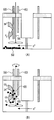
- FIG. 3 is a diagram for explaining the operation of the mixer 66 during the catalyst agitation control.
- 3A shows before the mixer 66 is driven
- FIG. 3B shows after the mixer 66 is driven.
- the CO 2 reduction catalyst 68 is a hydrophobic compound, and before the mixer 66 is stirred, they are collected and settled near the bottom surface of the cathode chamber 52 (FIG. 3A). Therefore, as shown in the figure, before the mixer 66 is stirred, only the proton reduction reaction proceeds on the WE 58 (the above formula (2)).
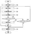
- FIG. 4 is a flowchart showing the catalyst agitation control executed by the control device 70 in the present embodiment. Note that the routine shown in FIG. 4 is repeatedly executed during operation of the mixed gas generation apparatus.
- the control device 70 starts stirring the mixer 66 (step 100). Thereby, the inside of the cathode chamber 52 is in the state shown in FIG. Subsequently, the control device 70 causes a current to flow between WE58 and CE62 so that the voltage between RE60 and WE58 becomes a predetermined value (step 110). Thus, the CO 2 reduction reaction (the above formula (1)) proceeds on the CO 2 reduction catalyst 68 in contact with the WE 58, and the proton reduction reaction (the above formula (2)) proceeds on the other WE 58. (Step 120). When executing the processing of steps 110 and 120, the control device 70 activates the temperature control device 12, the CO 2 valve 22, the liquid feed pumps 18, 28 and 42, and the mixed gas valve 36. As a result, the reactions of the above formulas (1) and (2) proceed continuously, so that CO gas and H 2 gas are generated and flow into the mixed gas tank 32.
- control device 70 detects the CO and H 2 concentrations in the mixed gas tank 32 from the concentration sensor 44 (step 130). Subsequently, the control device 70 obtains CO / H 2 from the CO and H 2 concentrations detected in step 130, and determines whether or not CO / H 2 > 1/2 is satisfied (step 140). As described above, since the volume of the mixed gas tank 32 is known, CO / H 2 can be obtained using the detection value from the concentration sensor 44.
- step 140 If it is determined in step 140 that CO / H 2 > 1/2, it can be determined that the amount of CO generated should be reduced and the amount of H 2 generated should be increased. Therefore, the control device 70 stops the stirring of the mixer 66 (step 150) and returns to step 110 again. If the procedure returns to step 110 with stirring of the mixer 66 stopped, the cathode chamber 52 is in the state shown in FIG. 3A, and therefore only H 2 can be generated on the WE 58. On the other hand, when it is determined in step 140 that CO / H 2 > 1/2 is not satisfied, the control device 70 determines whether CO / H 2 ⁇ 1/2 is satisfied (step 160). .
- CO / H 2 is obtained from the CO and H 2 concentrations obtained from the concentration sensor 44, and a KHCO 3 aqueous solution by the mixer 66 is obtained by comparing the obtained CO / H 2 with 1/2. Can be controlled. Therefore, CO / H 2 in the mixed gas tank 32 can always be maintained at 1 ⁇ 2.
- stirred for aqueous KHCO 3 may be other stirring device.
- a stirring bar such as a magnetic stirrer may be used instead of the mixer 66.
- a three-electrode electrolytic cell 50 is used, and a voltage is applied between RE 60 and WE 58 by a power source 64.
- CE 62 replaces RE 60.
- a two-electrode electrolytic cell that also serves as an electrode may be used. That is, any configuration that can apply a voltage between WE58 and CE62 can be applied as a modification of the electrolyzer 10 of the present embodiment.
- the diaphragm 56 is used between the cathode chamber 52 and the anode chamber 54, but the diaphragm 56 may be omitted.
- the KHCO 3 aqueous solution is circulated in the cathode chamber 52 and the like, but the circulated solution is not necessarily limited to this. That is, any liquid having CO 2 absorption characteristics to which a general electrolyte (supporting electrolyte) is added can be used instead of the KHCO 3 aqueous solution.
- water is provided in the anode chamber 54 and the like. However, any liquid that can generate protons by electrolysis can be used instead of water.
- the power source 64 corresponds to the “voltage applying means” in the first invention
- the mixer 66 corresponds to the “stirring means” in the first invention
- the control device 70 corresponds to the “control means” in the second invention.
- the concentration sensor 44 corresponds to the “substance amount acquisition unit” of the third aspect of the invention.
- Electrolyzer 12 Temperature controller 14 KHCO 3 tank 16, 26, 34, 38 Flow path 18, 28, 42 Liquid feed pump 20 CO 2 tank 22 CO 2 valve 24 Water tank 30 Gas-liquid separator 32 Mixed gas tank 36 Mixed gas valve 40 Concentrator 44 Concentration Sensor 50 Electrolyzer 52 Cathode Chamber 54 Anode Chamber 56 Diaphragm 58 Working Electrode 60 Reference Electrode 62 Counter Electrode 64 Power Source 66 Mixer 68 CO 2 Reduction Catalyst 70 Controller
Landscapes
- Chemical & Material Sciences (AREA)
- Organic Chemistry (AREA)
- Engineering & Computer Science (AREA)
- Chemical Kinetics & Catalysis (AREA)
- Electrochemistry (AREA)
- Materials Engineering (AREA)
- Metallurgy (AREA)
- Inorganic Chemistry (AREA)
- Automation & Control Theory (AREA)
- Electrolytic Production Of Non-Metals, Compounds, Apparatuses Therefor (AREA)
Abstract
この発明は、混合ガス生成装置に関し、所望の物質量比でCOおよびH2を同時生成可能な混合ガス生成装置を提供することを目的とする。 電解槽50は、KHCO3水溶液で満たされたカソード室52と、水で満たされたアノード室54とを備えている。カソード室52には、WE58、RE60およびミキサ66が配置されている。WE58は、電解槽50のカソードに相当するものであり、電気分解時にCO2を還元しにくい金属から構成されている。ミキサ66は、カソード室52内のKHCO3水溶液を撹拌する羽根型撹拌装置である。また、カソード室52の底面付近には、CO2を選択的にCOに還元する還元触媒として機能するCO2還元触媒68が沈殿した状態で配置されている。CO2還元触媒68は、疎水性の化合物であり、ミキサ66の駆動によりカソード室52内部に分散し、WE58の表面に接触する。
Description
この発明は、混合ガス生成装置に関する。より詳細には、電解装置を用いてH2、COからなる混合ガスを生成する混合ガス生成装置に関する。
石油、石炭、天然ガスといった化石燃料は、熱、電気の生成の原料や、運輸燃料として使用され、現代のエネルギー消費社会を支えている。しかし、このような化石燃料は使い切り燃料であり、その埋蔵量には限りがある。そのため、化石燃料が枯渇した場合の備えが必要であることは言うまでもない。また、化石燃料の燃焼によるCO2の大気中への放出は、地球温暖化の一要因となることが知られている。そのため、CO2の排出量を低減することが、近年の課題となっている。
これらの課題を解決する一つの手段として、CO2を原料とした代替燃料が検討されている。例えば、特許文献1には、CO2を原料として炭化水素系燃料(HC)を製造するシステムが開示されている。このシステムは、固体酸化物電解質から構成される酸素イオン伝導膜と、その両面にそれぞれ配置されたカソードおよびアノードと、を有する電解質セルを備えている。この電解質セルによれば、CO2ガスおよび水蒸気からCOガスおよびH2ガスをそれぞれ生成することができる。また、生成したCOガスおよびH2ガスを上記電解質セルから回収し、公知の製造装置内でフィッシャー・トロプシュ反応(FT反応)させればHCが得られる。
また、特許文献2には、FT反応時の原料ガス中のH2に対するCOの物質量比を1/4<CO/H2<2としたことが開示されている。原料ガス中の物質量比を上記範囲とすれば、エネルギー効率(投入エネルギーに対する生成物の発熱量をいう。以下同じ。)良くHCを製造できる。
上記特許文献1のシステムによれば、上記電解質セルからHCの原料ガスとなるH2およびCOを同時に生成できる。そのため、エネルギー効率良くHCを製造するためには、上記電解質セルからCOおよびH2を同時生成する際に、H2に対するCOの物質量比が1/4<CO/H2<2となるように電気分解すればよいことになる。しかし、上記電解質セルで生成するCOやH2の生成量は、上記電解質セルに供給するCO2ガスや水蒸気の単位時間当りの供給量といった電気分解条件に左右されてしまう。従って、所望の物質量比でCOおよびH2を同時生成するためには、その生成装置の構成レベルで更なる改良を行う必要があった。
この発明は、上述のような課題を解決するためになされたものである。即ち、所望の物質量比でCOおよびH2を同時生成可能な混合ガス生成装置を提供することを目的とする。
第1の発明は、上記の目的を達成するため、二酸化炭素と水とをそれぞれ電気分解して、一酸化炭素と水素とを含む混合ガスを生成する混合ガス生成装置であって、
所定濃度の二酸化炭素を含む電解質水溶液と、前記電解質水溶液に不溶であると共に、二酸化炭素の一酸化炭素への還元反応時に触媒として機能する不溶性還元触媒と、を内部に備える電解槽と、
前記電解槽に設けられたアノードおよびカソードと、
前記アノードおよびカソード間に電圧を印加する電圧印加手段と、
前記電解槽に設けられ前記電解槽内の電解質水溶液を撹拌する撹拌手段と、
を備えることを特徴とする。
所定濃度の二酸化炭素を含む電解質水溶液と、前記電解質水溶液に不溶であると共に、二酸化炭素の一酸化炭素への還元反応時に触媒として機能する不溶性還元触媒と、を内部に備える電解槽と、
前記電解槽に設けられたアノードおよびカソードと、
前記アノードおよびカソード間に電圧を印加する電圧印加手段と、
前記電解槽に設けられ前記電解槽内の電解質水溶液を撹拌する撹拌手段と、
を備えることを特徴とする。
また、第2の発明は、第1の発明において、
前記撹拌手段は、前記不溶性還元触媒が前記カソードに接触するように前記撹拌手段を制御する制御手段を備えることを特徴とする。
前記撹拌手段は、前記不溶性還元触媒が前記カソードに接触するように前記撹拌手段を制御する制御手段を備えることを特徴とする。
また、第3の発明は、第2の発明において、
前記電解槽で生成した混合ガス中の水素に対する一酸化炭素の物質量比を取得する物質量比取得手段を更に備え、
前記制御手段は、前記物質量比に応じて、前記不溶性還元触媒の前記カソードへの接触頻度を変更することを特徴とする。
前記電解槽で生成した混合ガス中の水素に対する一酸化炭素の物質量比を取得する物質量比取得手段を更に備え、
前記制御手段は、前記物質量比に応じて、前記不溶性還元触媒の前記カソードへの接触頻度を変更することを特徴とする。
また、第4の発明は、第3の発明において、
前記制御手段は、前記物質量比が設定比よりも小さい場合には前記接触頻度が増加するように前記撹拌手段を制御し、前記物質量比が前記設定比よりも大きい場合には前記撹拌手段の制御を停止することを特徴とする。
前記制御手段は、前記物質量比が設定比よりも小さい場合には前記接触頻度が増加するように前記撹拌手段を制御し、前記物質量比が前記設定比よりも大きい場合には前記撹拌手段の制御を停止することを特徴とする。
また、第5の発明は、第1乃至第4何れか1つの発明において、
前記電解槽は、前記電解質水溶液で満たされたカソード室と、水で満たされたアノード室と、前記アノード室と前記カソード室とを隔てるプロトン伝導性の隔膜と、を備えることを特徴とする。
前記電解槽は、前記電解質水溶液で満たされたカソード室と、水で満たされたアノード室と、前記アノード室と前記カソード室とを隔てるプロトン伝導性の隔膜と、を備えることを特徴とする。
また、第6の発明は、第5の発明において、
前記不溶性還元触媒および前記撹拌手段が、前記カソード室に設けられたことを特徴とする。
前記不溶性還元触媒および前記撹拌手段が、前記カソード室に設けられたことを特徴とする。
アノードおよびカソード間に電圧を印加すれば、電解質水溶液中の水が還元されてカソードにおいてH2が生成する。一方、電解質水溶液中のCO2は、電圧の印加だけでは還元され難いので、触媒の存在が必要となる。この点、第1の発明によれば、不溶性還元触媒を電解槽内に備えているので、電圧印加時に、その内の一部がカソードに接触することでCO2を還元できる。従って、本発明によれば、COおよびH2を同時に生成できる。
第2の発明によれば、制御手段によって、不溶性還元触媒がカソードに接触するように撹拌手段を制御できる。上述したように、電圧印加時に、不溶性還元触媒がカソードに接触すればCO2が還元される。そのため、この電圧印加時に更に撹拌手段を制御すれば、不溶性還元触媒のカソードへの接触頻度(以下、単に「接触頻度」と称す。)を制御できる。例えば、不溶性還元触媒を、撹拌手段の非制御時に電解槽の底面に沈殿させて接触頻度を低下させ、撹拌手段の制御時に電解質水溶液中に分散させて接触頻度を増加させることが可能となる。従って、本発明によれば、水やCO2の還元反応の進行を制御できるので、所望の物質量比でCOおよびH2を同時に生成できる。
第3の発明によれば、物質量比取得手段によって取得した物質量比に応じて、接触頻度を変更できる。上述したように、第2の発明によれば、接触頻度を制御して、水やCO2の還元反応の進行を制御できる。そのため、物質量比取得手段によって取得した物質量比に応じて接触頻度を変更すれば、生成する混合ガス中のH2に対するCOの物質量比を変更できる。従って、本発明によれば、H2に対するCOの物質量比を、所望の物質量比に調整できる。
第4の発明によれば、物質量比取得手段によって取得した物質量比が設定比よりも小さい場合には接触頻度が増加するように撹拌手段を制御できる。混合ガス中において、H2に対するCOの物質量比が設定比よりも小さい場合とは、H2の物質量が多くCOの物質量が少ないことを意味する。従って、接触頻度が増加するように撹拌手段を制御すれば、CO2の還元反応の進行を促進しCOの生成量を増やすことができる。また、第4の発明によれば、物質量比取得手段によって取得した物質量比が設定比よりも大きい場合には撹拌手段の制御を停止することができる。混合ガス中において、H2に対するCOの物質量比が設定比よりも大きい場合とは、H2の物質量が少なくCOの物質量が多いことを意味する。従って、撹拌手段の制御を停止すれば、水の還元反応のみ進行してH2の生成量を増やすことができる。以上のことから、本発明によれば、COとH2との物質量比が設定比となるように調整できる。
第5の発明によれば、プロトン伝導性の隔膜により、カソード室の電解質水溶液と、アノード室の水との混合を防止できる。プロトン伝導性の隔膜で混合を防止できれば、カソード室におけるCO2濃度やプロトン濃度の制御や、アノード室における水量の制御が容易となる。従って、本発明によれば、上記カソード室において生成する混合ガス中のH2に対するCOの物質量比を容易に調整できる。
第6の発明によれば、不溶性還元触媒および撹拌手段が上記カソード室に設けられているので、不溶性還元触媒をカソードへ確実に接触させることができる。従って、接触頻度の制御の精度を高めることができる。
[混合ガス生成装置の構成の説明]
以下、図1乃至図4を参照しながら、本発明の実施の形態について説明する。図1は、本発明の実施の形態の混合ガス生成装置の全体構成図である。図1に示すように、本実施形態の混合ガス生成装置は、電気分解によりCOガスおよびH2ガスを同時に生成する電解装置10を備えている。電解装置10は、その装置内温度を所定範囲内に制御する温度制御装置12付きの電気分解装置である。電解装置10の詳細な構成は、図2の説明の際に説明する。
以下、図1乃至図4を参照しながら、本発明の実施の形態について説明する。図1は、本発明の実施の形態の混合ガス生成装置の全体構成図である。図1に示すように、本実施形態の混合ガス生成装置は、電気分解によりCOガスおよびH2ガスを同時に生成する電解装置10を備えている。電解装置10は、その装置内温度を所定範囲内に制御する温度制御装置12付きの電気分解装置である。電解装置10の詳細な構成は、図2の説明の際に説明する。
電解装置10の上流側には、内部に炭酸水素カリウム(KHCO3)水溶液が貯留されたKHCO3タンク14が設けられている。KHCO3タンク14は、電解装置10と流路16を介して接続されている。流路16上には、KHCO3タンク14に貯留されたKHCO3水溶液を所定圧で流路16に供給するように構成された送液ポンプ18が設けられている。また、KHCO3タンク14は、内部にCO2ガスが充填されたCO2タンク20とCO2バルブ22を介して接続されている。
CO2バルブ22は、CO2タンク20内のCO2ガスをKHCO3タンク14内に供給するように構成されている。CO2バルブ22は電磁弁等により構成され、その開度は制御信号に応じて制御される。CO2バルブ22を開くことで、CO2タンク20とKHCO3タンク14とが相互に連通され、KHCO3タンク14内のKHCO3水溶液のCO2濃度が常時一定(例えば、CO2飽和状態)に保たれる。
また、電解装置10の上流側には、内部に水が貯留された水タンク24が設けられている。水タンク24は、電解装置10と流路26を介して接続されている。流路26上には、水タンク24に貯留された水を所定圧で流路26に供給するように構成された送液ポンプ28が設けられている。
一方、電解装置10の下流側には、気液分離器30が設けられている。後述するように、電解装置10のカソード室において、CO、H2およびH2Oが生成される。これらの生成物は、KHCO3水溶液と混合した状態で電解装置10から排出され、気液分離器30に送られて気液分離される。
気液分離器30の下流側には、混合ガスタンク32が設けられている。混合ガスタンク32は、密閉構造を有する耐圧容器(容積既知)であり、流路34を介して気液分離器30と接続されている。流路34には、開度を制御可能に構成された混合ガスバルブ36が設けられている。混合ガスバルブ36は、CO2バルブ22同様、電磁弁等により構成され、その開度は制御信号に応じて制御される。混合ガスバルブ36を開くことで、気液分離器30と混合ガスタンク32とが相互に連通され、気液分離器30で分離されたCO、H2からなる混合ガスが、混合ガスタンク32に流入する。
気液分離器30は、流路38を介してKHCO3タンク14に接続されている。流路38上には、濃縮装置40、送液ポンプ42が設けられている。濃縮装置40は、内部に加熱装置と冷却装置とを備えたものであり、KHCO3水溶液から生成水相当量の水分を加熱除去し、その後、混合ガスタンク32内のKHCO3水溶液の温度と略等しい温度まで冷却するように構成されている。送液ポンプ42は、冷却後のKHCO3水溶液を所定圧で流路38に供給するように構成されている。送液ポンプ18,42は、KHCO3タンク14、電解装置10、気液分離器30、濃縮装置40にKHCO3水溶液を循環させる循環ポンプとして機能する。
本実施形態の混合ガス生成装置は、更に、制御装置70を備えている。制御装置70の入力側には、上述した温度制御装置12の他、混合ガスタンク32内のCO、H2の濃度を検出する濃度センサ44が接続されている。また、制御装置70の出力側には、電解装置10、温度制御装置12、CO2バルブ22、送液ポンプ18,28,42、混合ガスバルブ36や濃縮装置40が接続されている。
[電解装置10の構成の説明]
次に、図2を参照しながら、電解装置10の構成について詳細に説明する。図2は、図1の電解装置10の概略図である。電解装置10は、3電極式の電解槽50を備えている。電解槽50は、KHCO3水溶液で満たされたカソード室52と、水で満たされたアノード室54と、カソード室52とアノード室54とを仕切る隔膜56とを備えている。
次に、図2を参照しながら、電解装置10の構成について詳細に説明する。図2は、図1の電解装置10の概略図である。電解装置10は、3電極式の電解槽50を備えている。電解槽50は、KHCO3水溶液で満たされたカソード室52と、水で満たされたアノード室54と、カソード室52とアノード室54とを仕切る隔膜56とを備えている。
カソード室52には、図1のKHCO3タンク14や気液分離器30が接続されている。また、カソード室52には、作用極(WE)58、参照極(RE)60およびミキサ66が配置されている。WE58は、電解槽50のカソードに相当するものであり、電気分解時にCO2を還元しにくい金属(例えば、Pt)から構成されている。ミキサ66は、カソード室52内のKHCO3水溶液を撹拌する羽根型撹拌装置である。
また、カソード室52の底面付近には、CO2を選択的にCOに還元する還元触媒として機能するCO2還元触媒68が沈殿した状態で配置されている。CO2還元触媒68は、疎水性の化合物(即ち、KHCO3水溶液に不溶な化合物)であり、例えば、日本特開平4-13883に開示された有機金属錯体が挙げられる。なお、図面中におけるCO2還元触媒68は、説明の便宜上可視化したものであり、必ずしも図示した様に沈殿するとは限らない。
また、アノード室54には、図1の水タンク24が接続されている。また、アノード室54には、対極(CE)62が配置されている。CE62は、電解槽50のアノードに相当するものであり、電気分解時に溶解しない金属(例えば、Au、Pt)から構成されている。
また、隔膜56は、アノード室54側からカソード室52側にプロトンを運搬する機能を有するものであり、例えばNAFION(登録商標)等の高分子電解質から構成されている。
また、電解装置10は、電源64を備えている。電源64は、WE58、RE60、CE62、図1の制御装置70に接続されている。電源64は、RE60とWE58の間の電圧が所定値となるようにWE58とCE62の間に流す電流値を制御する。
ここで、電解装置10における電気分解について説明する。ミキサ66を駆動してKHCO3水溶液を撹拌しつつ、電源64を制御してWE58とCE62の間に電流を流すと、WE58、CE62において、下記式(1)~(3)の電気化学反応が起こる。
WE58:CO2+2H++2e-→CO+H2O ・・・(1)
2H++2e-→H2 ・・・(2)
CE62:2H2O→O2+4H++4e- ・・・(3)
WE58:CO2+2H++2e-→CO+H2O ・・・(1)
2H++2e-→H2 ・・・(2)
CE62:2H2O→O2+4H++4e- ・・・(3)
上記式(1)の反応は、ミキサ66の駆動によりWE58と電気的に接続されたCO2還元触媒68が、KHCO3水溶液に接する箇所において進行する。また、上記式(2)の反応は、WE58の本体部分がKHCO3水溶液に接する箇所において進行する。また、上記式(3)の反応は、CE62が水に接する箇所において進行する。
WE58とCE62の間に電流を流しながら、送液ポンプ28を駆動して水をアノード室54に供給すれば、CE62上において、プロトンを連続的に生成することができる(上記式(3))。この際、送液ポンプ18を駆動してKHCO3水溶液をカソード室52に供給すれば、カソード室52にCO2、プロトンを連続的に供給できる。従って、WE58とCE62の間に電流を流しつつ送液ポンプ18,28およびミキサ66を駆動すれば、WE58上において、COおよびH2を連続的に生成し続けることができる(上記式(1)、(2))。COおよびH2は、KHCO3水溶液に対する溶解度が低いので、生成したCOおよびH2のほぼ全量は、ガスとして存在することになる。
[実施の形態の特徴]
上述したように、COおよびH2からHCを合成する反応としてFT反応が公知である。また、COとH2の混合比率を1/4<CO/H2<2とすればエネルギー効率よくHCを合成でき、CO/H2=1/2とすれば、特にエネルギー効率よくHCを合成できることが分かっている。この点、電解装置10によれば、WE58上でCOおよびH2を同時に生成できる。そのため、生成比率を予めCO/H2=1/2としておけば、原料生成と比率調整とを同時進行させることができる。原料生成と比率調整とを同時進行できれば、生成したCOおよびH2をそのままFT反応に投入できる。従って、HCを原料段階からエネルギー効率よく製造できる。
上述したように、COおよびH2からHCを合成する反応としてFT反応が公知である。また、COとH2の混合比率を1/4<CO/H2<2とすればエネルギー効率よくHCを合成でき、CO/H2=1/2とすれば、特にエネルギー効率よくHCを合成できることが分かっている。この点、電解装置10によれば、WE58上でCOおよびH2を同時に生成できる。そのため、生成比率を予めCO/H2=1/2としておけば、原料生成と比率調整とを同時進行させることができる。原料生成と比率調整とを同時進行できれば、生成したCOおよびH2をそのままFT反応に投入できる。従って、HCを原料段階からエネルギー効率よく製造できる。
ところで、本発明者らの知見によれば、RE60とWE58の間に定電位を印加すれば、H2に対するCOの生成比率を一定にできることが明らかとなっている。しかしながら、定電位での電気分解では、その電位に対応する生成比率に固定されてしまうので、目的の生成比率以外の生成比率となるような場合には、その微調整が必要となる。そこで、本実施の形態においては、濃度センサ44の検出値に基づいて、ミキサ66の駆動を制御することとした(触媒撹拌制御)。
図3は、触媒撹拌制御時におけるミキサ66の動作を説明するための図である。図3(A)はミキサ66の駆動前を、同図(B)はミキサ66の駆動後を、それぞれ示す。上述したように、CO2還元触媒68は疎水性の化合物であり、ミキサ66の撹拌前はそれらが集積しカソード室52の底面付近に沈殿した状態となる(図3(A))。従って、図中に示すように、ミキサ66の撹拌前においては、WE58上でプロトンの還元反応のみが進行する(上記式(2))。
一方、ミキサ66を駆動してKHCO3水溶液を撹拌すると、CO2還元触媒68がカソード室52内部に分散し、その一部はWE58の表面に接触することになる(図3(B))。従って、図中に示すように、ミキサ66の撹拌後においては、WE58に接触したCO2還元触媒68上でCO2の還元反応が進行し(上記式(1))、それ以外のWE58上でプロトンの還元反応が進行する(上記式(2))。
このようにミキサ66を作動させれば、ミキサ66の停止時にH2ガスのみを生成し、ミキサ66の駆動時にCOおよびH2を生成することができる。つまり、ミキサ66の駆動によりH2やCOの生成量を調整できる。そのため、例えば濃度センサ44の検出値によって、COの生成量が少ないと判断される場合に、ミキサ66の撹拌を継続させてCOの生成量を増加させることができる。従って、触媒撹拌制御によれば、H2に対するCOの生成比率を所望値に調整可能となるので、CO/H2=1/2への調整も容易に可能となる。
[実施の形態における具体的な処理]
次に、図4を参照しながら、上述した触媒撹拌制御を実現するための具体的処理について説明する。図4は、本実施形態において、制御装置70により実行される触媒撹拌制御を示すフローチャートである。なお、図4に示すルーチンは、混合ガス生成装置の稼働中に繰り返し実行されるものとする。
次に、図4を参照しながら、上述した触媒撹拌制御を実現するための具体的処理について説明する。図4は、本実施形態において、制御装置70により実行される触媒撹拌制御を示すフローチャートである。なお、図4に示すルーチンは、混合ガス生成装置の稼働中に繰り返し実行されるものとする。
図4に示すルーチンでは、先ず制御装置70は、ミキサ66の撹拌を開始する(ステップ100)。これにより、カソード室52内は図3(B)の状態となる。続いて、制御装置70は、RE60とWE58の間の電圧が所定値となるように、WE58とCE62の間に電流を流す(ステップ110)。これにより、WE58に接触したCO2還元触媒68上ではCO2の還元反応(上記式(1))が進行し、それ以外のWE58上ではプロトンの還元反応(上記式(2))が進行する(ステップ120)。なお、ステップ110、120の処理の実行に際し、制御装置70は、温度制御装置12、CO2バルブ22、送液ポンプ18,28,42や、混合ガスバルブ36を起動する。これにより、上記式(1)および(2)の反応が連続的に進行するので、COガス、H2ガスが発生し混合ガスタンク32内に流入する。
続いて、制御装置70は、濃度センサ44から、混合ガスタンク32内のCO、H2濃度を検出する(ステップ130)。続いて、制御装置70は、ステップ130で検出したCO、H2濃度からCO/H2を求め、CO/H2>1/2を満たすか否かを判定する(ステップ140)。上述したように、混合ガスタンク32は容積既知であるため、濃度センサ44からの検出値を利用して、CO/H2を求めることができる。
ステップ140において、CO/H2>1/2と判定された場合は、COの生成量を減らし、H2の生成量を増やせばよいと判断できる。従って、制御装置70は、ミキサ66の撹拌を停止し(ステップ150)、再びステップ110に戻る。ミキサ66の撹拌を停止した状態でステップ110に戻れば、カソード室52内は図3(A)の状態となるので、WE58上でH2のみを生成することができる。一方、ステップ140において、CO/H2>1/2を満たさないと判定された場合には、制御装置70は、CO/H2<1/2を満たすか否かを判定する(ステップ160)。
ステップ160において、CO/H2<1/2と判定された場合は、COの生成量を増やせばよいと判断できる。従って、制御装置70は、ステップ110に戻る。ステップ110に戻れば、カソード室52内は図3(B)の状態が維持されるので、WE58上でCOおよびH2を生成することができる。一方、CO/H2<1/2を満たさない、即ち、CO/H2=1/2と判定された場合は、COやH2の生成量の調整が不要と判断できるので、電気分解を終了する(ステップ170)。
以上、図4のルーチンによれば、濃度センサ44から取得したCO、H2濃度からCO/H2を求め、求めたCO/H2と1/2との比較によって、ミキサ66によるKHCO3水溶液の撹拌を制御することができる。従って、混合ガスタンク32内のCO/H2を、常に1/2に維持することが可能となる。
ところで、本実施の形態においては、ミキサ66を用いてカソード室52内のKHCO3水溶液を撹拌したが、KHCO3水溶液の撹拌は、他の撹拌装置を用いてもよい。例えば、ミキサ66の代わりに、マグネチックスターラーといった撹拌子を用いてもよい。
また、本実施の形態においては、3電極式の電解槽50を使用し、電源64によりRE60とWE58の間に電圧を印加したが、3電極式の電解槽50の代わりに、CE62がRE60を兼ねる2電極式の電解槽を使用してもよい。即ち、WE58とCE62の間に電圧を印加できる構成であれば、本実施の形態の電解装置10の変形例として適用が可能である。
また、本実施の形態においては、カソード室52とアノード室54との間に隔膜56を使用したが、隔膜56は省略されていてもよい。
また、本実施の形態においては、カソード室52等にKHCO3水溶液を循環させたが、循環させる溶液は必ずしもこれに限られない。即ち、一般的な電解質(支持電解質)が添加されたCO2吸収特性を有する液体であれば、KHCO3水溶液の代わりに用いることができる。同様に、本実施の形態においては、アノード室54等に水を設けたが、電気分解によりプロトンを生成可能な液体であれば、水の代わりに用いることができる。
なお、本実施の形態においては、電源64が上記第1の発明における「電圧印加手段」に、ミキサ66が上記第1の発明における「撹拌手段」にそれぞれ相当する。
また、本実施の形態においては、制御装置70が上記第2の発明における「制御手段」に、夫々相当する。
また、本実施の形態においては、濃度センサ44が上記第3の発明の「物質量比取得手段」に相当する。
また、本実施の形態においては、制御装置70が上記第2の発明における「制御手段」に、夫々相当する。
また、本実施の形態においては、濃度センサ44が上記第3の発明の「物質量比取得手段」に相当する。
10 電解装置
12 温度制御装置
14 KHCO3タンク
16,26,34,38 流路
18,28,42 送液ポンプ
20 CO2タンク
22 CO2バルブ
24 水タンク
30 気液分離器
32 混合ガスタンク
36 混合ガスバルブ
40 濃縮装置
44 濃度センサ
50 電解槽
52 カソード室
54 アノード室
56 隔膜
58 作用極
60 参照極
62 対極
64 電源
66 ミキサ
68 CO2還元触媒
70 制御装置
12 温度制御装置
14 KHCO3タンク
16,26,34,38 流路
18,28,42 送液ポンプ
20 CO2タンク
22 CO2バルブ
24 水タンク
30 気液分離器
32 混合ガスタンク
36 混合ガスバルブ
40 濃縮装置
44 濃度センサ
50 電解槽
52 カソード室
54 アノード室
56 隔膜
58 作用極
60 参照極
62 対極
64 電源
66 ミキサ
68 CO2還元触媒
70 制御装置
Claims (6)
- 二酸化炭素と水とをそれぞれ電気分解して、一酸化炭素と水素とを含む混合ガスを生成する混合ガス生成装置であって、
所定濃度の二酸化炭素を含む電解質水溶液と、前記電解質水溶液に不溶であると共に、二酸化炭素の一酸化炭素への還元反応時に触媒として機能する不溶性還元触媒と、を内部に備える電解槽と、
前記電解槽に設けられたアノードおよびカソードと、
前記アノードおよびカソード間に電圧を印加する電圧印加手段と、
前記電解槽に設けられ前記電解槽内の電解質水溶液を撹拌する撹拌手段と、
を備えることを特徴とする混合ガス生成装置。 - 前記撹拌手段は、前記不溶性還元触媒が前記カソードに接触するように前記撹拌手段を制御する制御手段を備えることを特徴とする請求項1に記載の混合ガス生成装置。
- 前記電解槽で生成した混合ガス中の水素に対する一酸化炭素の物質量比を取得する物質量比取得手段を更に備え、
前記制御手段は、前記物質量比に応じて、前記不溶性還元触媒の前記カソードへの接触頻度を変更することを特徴とする請求項2に記載の混合ガス生成装置。 - 前記制御手段は、前記物質量比が設定比よりも小さい場合には前記接触頻度が増加するように前記撹拌手段を制御し、前記物質量比が前記設定比よりも大きい場合には前記撹拌手段の制御を停止することを特徴とする請求項3に記載の混合ガス生成装置。
- 前記電解槽は、前記電解質水溶液で満たされたカソード室と、水で満たされたアノード室と、前記アノード室と前記カソード室とを隔てるプロトン伝導性の隔膜と、を備えることを特徴とする請求項1乃至4何れか1項に記載の混合ガス生成装置。
- 前記不溶性還元触媒および前記撹拌手段が、前記カソード室に設けられたことを特徴とする請求項5に記載の混合ガス生成装置。
Priority Applications (1)
| Application Number | Priority Date | Filing Date | Title |
|---|---|---|---|
| PCT/JP2011/058895 WO2012137344A1 (ja) | 2011-04-08 | 2011-04-08 | 混合ガス生成装置 |
Applications Claiming Priority (1)
| Application Number | Priority Date | Filing Date | Title |
|---|---|---|---|
| PCT/JP2011/058895 WO2012137344A1 (ja) | 2011-04-08 | 2011-04-08 | 混合ガス生成装置 |
Publications (1)
| Publication Number | Publication Date |
|---|---|
| WO2012137344A1 true WO2012137344A1 (ja) | 2012-10-11 |
Family
ID=46968779
Family Applications (1)
| Application Number | Title | Priority Date | Filing Date |
|---|---|---|---|
| PCT/JP2011/058895 Ceased WO2012137344A1 (ja) | 2011-04-08 | 2011-04-08 | 混合ガス生成装置 |
Country Status (1)
| Country | Link |
|---|---|
| WO (1) | WO2012137344A1 (ja) |
Cited By (7)
| Publication number | Priority date | Publication date | Assignee | Title |
|---|---|---|---|---|
| JP2017160476A (ja) * | 2016-03-08 | 2017-09-14 | 富士通株式会社 | 二酸化炭素還元装置 |
| US20180094355A1 (en) * | 2016-10-04 | 2018-04-05 | Johna Leddy | Carbon dioxide reduction and carbon compound electrochemistry in the presence of lanthanides |
| WO2019049476A1 (ja) * | 2017-09-05 | 2019-03-14 | 千代田化工建設株式会社 | 合成ガス生成システム |
| JP2020500258A (ja) * | 2016-08-29 | 2020-01-09 | ダイオキサイド マテリアルズ,インコーポレイティド | 再生可能燃料および化学品を製造するための装置および方法 |
| CN116637505A (zh) * | 2023-06-28 | 2023-08-25 | 郑州轻工业大学 | 一种流化催化气体还原反应器及其方法 |
| JP2023142159A (ja) * | 2022-03-24 | 2023-10-05 | 一般財団法人電力中央研究所 | Co2回収システム、発電設備 |
| CN117626300A (zh) * | 2023-12-04 | 2024-03-01 | 东南大学 | 基于管式透散电极的流动池反应系统及运行方法 |
Citations (3)
| Publication number | Priority date | Publication date | Assignee | Title |
|---|---|---|---|---|
| JPS6415388A (en) * | 1987-07-07 | 1989-01-19 | Terumo Corp | Electrode for reducing gaseous carbon dioxide |
| JPH0959791A (ja) * | 1995-08-24 | 1997-03-04 | Mitsui Mining & Smelting Co Ltd | 亜鉛電解液中の塩素濃度の低減法 |
| JP2004176129A (ja) * | 2002-11-27 | 2004-06-24 | Kotaro Ogura | 二酸化炭素からのエチレンの選択的製造方法 |
-
2011
- 2011-04-08 WO PCT/JP2011/058895 patent/WO2012137344A1/ja not_active Ceased
Patent Citations (3)
| Publication number | Priority date | Publication date | Assignee | Title |
|---|---|---|---|---|
| JPS6415388A (en) * | 1987-07-07 | 1989-01-19 | Terumo Corp | Electrode for reducing gaseous carbon dioxide |
| JPH0959791A (ja) * | 1995-08-24 | 1997-03-04 | Mitsui Mining & Smelting Co Ltd | 亜鉛電解液中の塩素濃度の低減法 |
| JP2004176129A (ja) * | 2002-11-27 | 2004-06-24 | Kotaro Ogura | 二酸化炭素からのエチレンの選択的製造方法 |
Cited By (12)
| Publication number | Priority date | Publication date | Assignee | Title |
|---|---|---|---|---|
| JP2017160476A (ja) * | 2016-03-08 | 2017-09-14 | 富士通株式会社 | 二酸化炭素還元装置 |
| JP2020500258A (ja) * | 2016-08-29 | 2020-01-09 | ダイオキサイド マテリアルズ,インコーポレイティド | 再生可能燃料および化学品を製造するための装置および方法 |
| US20180094355A1 (en) * | 2016-10-04 | 2018-04-05 | Johna Leddy | Carbon dioxide reduction and carbon compound electrochemistry in the presence of lanthanides |
| US10774430B2 (en) * | 2016-10-04 | 2020-09-15 | Johna Leddy | Carbon dioxide reduction and carbon compound electrochemistry in the presence of lanthanides |
| WO2019049476A1 (ja) * | 2017-09-05 | 2019-03-14 | 千代田化工建設株式会社 | 合成ガス生成システム |
| JP2019044238A (ja) * | 2017-09-05 | 2019-03-22 | 千代田化工建設株式会社 | 合成ガス生成システム |
| US11268198B2 (en) | 2017-09-05 | 2022-03-08 | Chiyoda Corporation | Synthesis gas production system |
| JP2023142159A (ja) * | 2022-03-24 | 2023-10-05 | 一般財団法人電力中央研究所 | Co2回収システム、発電設備 |
| CN116637505A (zh) * | 2023-06-28 | 2023-08-25 | 郑州轻工业大学 | 一种流化催化气体还原反应器及其方法 |
| CN117626300A (zh) * | 2023-12-04 | 2024-03-01 | 东南大学 | 基于管式透散电极的流动池反应系统及运行方法 |
| WO2025118952A1 (zh) * | 2023-12-04 | 2025-06-12 | 东南大学 | 基于管式透散电极的流动池反应系统及运行方法 |
| CN117626300B (zh) * | 2023-12-04 | 2025-12-26 | 东南大学 | 基于管式透散电极的流动池反应系统及运行方法 |
Similar Documents
| Publication | Publication Date | Title |
|---|---|---|
| Ross et al. | Designing materials for electrochemical carbon dioxide recycling | |
| WO2012137344A1 (ja) | 混合ガス生成装置 | |
| Kumari et al. | Synergistic plasma-assisted electrochemical reduction of nitrogen to ammonia | |
| Jones et al. | Electrochemical CO2 reduction: recent advances and current trends | |
| JPWO2012077198A1 (ja) | 燃料製造システム | |
| Tuomi et al. | Hydrogen production by methanol–water solution electrolysis with an alkaline membrane cell | |
| KR20210103780A (ko) | 수전해 시스템 및 그 제어방법 | |
| WO2012077199A1 (ja) | 混合ガス生成装置および混合ガス生成システム | |
| Anastasiadou et al. | Electrocatalytic synthesis of organic carbonates | |
| Islam et al. | The effects of power ultrasound (24 kHz) on the electrochemical reduction of CO2 on polycrystalline copper electrodes | |
| Zhang et al. | Unravelling the carbonate issue through the regulation of mass transport and charge transfer in mild acid | |
| Song et al. | Methane bubbled through seawater can be converted to methanol with high efficiency | |
| Lin et al. | Ampere-level plasma-electrosynthesis of ammonia via a Cu0/Cu+-enriched heterogeneous catalyst | |
| JP2015004112A (ja) | 電解合成装置 | |
| Li et al. | Elevated temperature and pressure driven ampere-level CO 2 electroreduction to CO in a membrane electrode assembly electrolyzer | |
| Ahn et al. | Pulsed laser-tuned ruthenium@ carbon interface for self-powered hydrogen production via zinc–hydrazine battery coupled hybrid electrolysis | |
| Lv et al. | In–depth understanding on the mechanism of ionic liquid-assisted enhancement of electrochemical CO2 reduction to formic acid | |
| Wu et al. | Oxygen vacancies enhance non-Faradaic deprotonation in furfural electro-oxidation | |
| JP2009079149A (ja) | エマルション燃料製造装置及びエマルション燃料の製造方法 | |
| Schalck et al. | The electrosynthesis of ethylene oxide in a tandem recycle flow reactor system | |
| Mahmoudian et al. | Improved chloralkaline reversible electrochemical cells featuring a catalytic-coating-free 3-D printed titanium gas diffusion electrode | |
| Carlesi et al. | Analysis of carbon dioxide-to-methanol direct electrochemical conversion mediated by an ionic liquid | |
| Frangini et al. | A novel process for solar hydrogen production based on water electrolysis in alkali molten carbonates | |
| JP2013256679A (ja) | 電解システム | |
| Cavaliere | Thermochemical Water Splitting Cycles |
Legal Events
| Date | Code | Title | Description |
|---|---|---|---|
| 121 | Ep: the epo has been informed by wipo that ep was designated in this application |
Ref document number: 11863177 Country of ref document: EP Kind code of ref document: A1 |
|
| NENP | Non-entry into the national phase |
Ref country code: DE |
|
| 122 | Ep: pct application non-entry in european phase |
Ref document number: 11863177 Country of ref document: EP Kind code of ref document: A1 |
|
| NENP | Non-entry into the national phase |
Ref country code: JP |