WO2012137327A1 - 携帯情報表示端末 - Google Patents
携帯情報表示端末 Download PDFInfo
- Publication number
- WO2012137327A1 WO2012137327A1 PCT/JP2011/058737 JP2011058737W WO2012137327A1 WO 2012137327 A1 WO2012137327 A1 WO 2012137327A1 JP 2011058737 W JP2011058737 W JP 2011058737W WO 2012137327 A1 WO2012137327 A1 WO 2012137327A1
- Authority
- WO
- WIPO (PCT)
- Prior art keywords
- state
- face
- user
- portable information
- orientation
- Prior art date
- Legal status (The legal status is an assumption and is not a legal conclusion. Google has not performed a legal analysis and makes no representation as to the accuracy of the status listed.)
- Ceased
Links
Images






Classifications
-
- G—PHYSICS
- G09—EDUCATION; CRYPTOGRAPHY; DISPLAY; ADVERTISING; SEALS
- G09G—ARRANGEMENTS OR CIRCUITS FOR CONTROL OF INDICATING DEVICES USING STATIC MEANS TO PRESENT VARIABLE INFORMATION
- G09G5/00—Control arrangements or circuits for visual indicators common to cathode-ray tube indicators and other visual indicators
-
- H—ELECTRICITY
- H04—ELECTRIC COMMUNICATION TECHNIQUE
- H04N—PICTORIAL COMMUNICATION, e.g. TELEVISION
- H04N21/00—Selective content distribution, e.g. interactive television or video on demand [VOD]
- H04N21/40—Client devices specifically adapted for the reception of or interaction with content, e.g. set-top-box [STB]; Operations thereof
- H04N21/43—Processing of content or additional data, e.g. demultiplexing additional data from a digital video stream; Elementary client operations, e.g. monitoring of home network or synchronising decoder's clock; Client middleware
- H04N21/442—Monitoring of processes or resources, e.g. detecting the failure of a recording device, monitoring the downstream bandwidth, the number of times a movie has been viewed, the storage space available from the internal hard disk
- H04N21/44213—Monitoring of end-user related data
- H04N21/44218—Detecting physical presence or behaviour of the user, e.g. using sensors to detect if the user is leaving the room or changes his face expression during a TV programme
-
- G—PHYSICS
- G06—COMPUTING OR CALCULATING; COUNTING
- G06F—ELECTRIC DIGITAL DATA PROCESSING
- G06F1/00—Details not covered by groups G06F3/00 - G06F13/00 and G06F21/00
- G06F1/16—Constructional details or arrangements
- G06F1/1613—Constructional details or arrangements for portable computers
- G06F1/1626—Constructional details or arrangements for portable computers with a single-body enclosure integrating a flat display, e.g. Personal Digital Assistants [PDAs]
-
- G—PHYSICS
- G06—COMPUTING OR CALCULATING; COUNTING
- G06F—ELECTRIC DIGITAL DATA PROCESSING
- G06F1/00—Details not covered by groups G06F3/00 - G06F13/00 and G06F21/00
- G06F1/16—Constructional details or arrangements
- G06F1/1613—Constructional details or arrangements for portable computers
- G06F1/1633—Constructional details or arrangements of portable computers not specific to the type of enclosures covered by groups G06F1/1615 - G06F1/1626
- G06F1/1684—Constructional details or arrangements related to integrated I/O peripherals not covered by groups G06F1/1635 - G06F1/1675
- G06F1/1694—Constructional details or arrangements related to integrated I/O peripherals not covered by groups G06F1/1635 - G06F1/1675 the I/O peripheral being a single or a set of motion sensors for pointer control or gesture input obtained by sensing movements of the portable computer
-
- G—PHYSICS
- G06—COMPUTING OR CALCULATING; COUNTING
- G06F—ELECTRIC DIGITAL DATA PROCESSING
- G06F3/00—Input arrangements for transferring data to be processed into a form capable of being handled by the computer; Output arrangements for transferring data from processing unit to output unit, e.g. interface arrangements
- G06F3/01—Input arrangements or combined input and output arrangements for interaction between user and computer
- G06F3/011—Arrangements for interaction with the human body, e.g. for user immersion in virtual reality
- G06F3/012—Head tracking input arrangements
-
- G—PHYSICS
- G06—COMPUTING OR CALCULATING; COUNTING
- G06F—ELECTRIC DIGITAL DATA PROCESSING
- G06F3/00—Input arrangements for transferring data to be processed into a form capable of being handled by the computer; Output arrangements for transferring data from processing unit to output unit, e.g. interface arrangements
- G06F3/01—Input arrangements or combined input and output arrangements for interaction between user and computer
- G06F3/03—Arrangements for converting the position or the displacement of a member into a coded form
- G06F3/0304—Detection arrangements using opto-electronic means
-
- G—PHYSICS
- G06—COMPUTING OR CALCULATING; COUNTING
- G06F—ELECTRIC DIGITAL DATA PROCESSING
- G06F3/00—Input arrangements for transferring data to be processed into a form capable of being handled by the computer; Output arrangements for transferring data from processing unit to output unit, e.g. interface arrangements
- G06F3/01—Input arrangements or combined input and output arrangements for interaction between user and computer
- G06F3/048—Interaction techniques based on graphical user interfaces [GUI]
-
- G—PHYSICS
- G09—EDUCATION; CRYPTOGRAPHY; DISPLAY; ADVERTISING; SEALS
- G09G—ARRANGEMENTS OR CIRCUITS FOR CONTROL OF INDICATING DEVICES USING STATIC MEANS TO PRESENT VARIABLE INFORMATION
- G09G3/00—Control arrangements or circuits, of interest only in connection with visual indicators other than cathode-ray tubes
- G09G3/20—Control arrangements or circuits, of interest only in connection with visual indicators other than cathode-ray tubes for presentation of an assembly of a number of characters, e.g. a page, by composing the assembly by combination of individual elements arranged in a matrix no fixed position being assigned to or needed to be assigned to the individual characters or partial characters
-
- G—PHYSICS
- G09—EDUCATION; CRYPTOGRAPHY; DISPLAY; ADVERTISING; SEALS
- G09G—ARRANGEMENTS OR CIRCUITS FOR CONTROL OF INDICATING DEVICES USING STATIC MEANS TO PRESENT VARIABLE INFORMATION
- G09G5/00—Control arrangements or circuits for visual indicators common to cathode-ray tube indicators and other visual indicators
- G09G5/36—Control arrangements or circuits for visual indicators common to cathode-ray tube indicators and other visual indicators characterised by the display of a graphic pattern, e.g. using an all-points-addressable [APA] memory
-
- H—ELECTRICITY
- H04—ELECTRIC COMMUNICATION TECHNIQUE
- H04N—PICTORIAL COMMUNICATION, e.g. TELEVISION
- H04N7/00—Television systems
- H04N7/16—Analogue secrecy systems; Analogue subscription systems
- H04N7/173—Analogue secrecy systems; Analogue subscription systems with two-way working, e.g. subscriber sending a programme selection signal
-
- G—PHYSICS
- G06—COMPUTING OR CALCULATING; COUNTING
- G06F—ELECTRIC DIGITAL DATA PROCESSING
- G06F2200/00—Indexing scheme relating to G06F1/04 - G06F1/32
- G06F2200/16—Indexing scheme relating to G06F1/16 - G06F1/18
- G06F2200/163—Indexing scheme relating to constructional details of the computer
- G06F2200/1637—Sensing arrangement for detection of housing movement or orientation, e.g. for controlling scrolling or cursor movement on the display of an handheld computer
Definitions
- the present invention relates to a portable information display terminal, and more particularly to a portable information display terminal including a display unit and a casing provided with the display unit.
- a portable information display terminal including a display unit and a casing provided with the display unit is known.
- Such a portable information display terminal is disclosed in, for example, Japanese Unexamined Patent Application Publication No. 2009-130816.
- Japanese Patent Laid-Open No. 2009-130816 discloses a display unit that displays a television broadcast video (screen display), a mobile phone body (housing) provided with a display unit on the surface, and a camera that can capture a user's face (imaging) A mobile phone (portable information display terminal).
- the mobile phone according to Japanese Patent Application Laid-Open No. 2009-130816 takes a user's face by using a camera when the user starts viewing a television broadcast video with the display unit while holding the mobile phone body.
- TV broadcast video is displayed on the display unit in a display direction corresponding to the orientation of the face.
- the present invention has been made to solve the above-described problems, and one object of the present invention is to display a screen with an appropriate display orientation even when the orientation of the user's face cannot be detected. It is to provide a portable information display terminal capable of displaying.
- a portable information display terminal includes a display unit for displaying information, a casing on which the display unit is provided, and at least a usage state of the casing and the display unit by detecting the tilt of the casing.
- a state detection sensor for detecting the image of the user, an imaging unit capable of imaging the user's face, and detecting the orientation of the face using the face detection function based on the user's face data captured by the imaging unit.
- a control unit that performs control to switch the screen display direction of the display unit based on the detection result of the direction and the detection result of the state detection sensor is provided.
- the screen of the display unit is based on the detection result of the face direction of the user detected by the face detection function and the detection result by the state detection sensor.
- the state detection sensor that detects the tilt of the housing can detect what state (posture) the housing is in.
- the control unit preferably detects the use state of the housing and the display unit by the state detection sensor, and then based on the detection result by the state detection sensor, Control is performed to determine whether or not to detect the face orientation.
- the state detection sensor it is necessary to detect the usage state of the housing and the display unit by the state detection sensor before starting the imaging unit, and to start the imaging unit according to the detection result by the state detection sensor. Can be determined.
- an operation process that unnecessarily activates the imaging unit is not performed. Can be done quickly.
- the control unit when a predetermined use state is detected by the state detection sensor, the control unit is more sensitive to the user's face than the use state detected by the state detection sensor.
- the orientation detection result is prioritized and the screen display orientation corresponding to the orientation of the user's face is switched. If configured in this way, in the case of a predetermined use state in which it is likely that the screen display direction based on the detection result of the user's face direction and the screen display direction based on the inclination by the state detection sensor are likely to occur. By giving priority to the detection result of the face orientation, it is possible to display the screen display orientation more suitable for the actual usage mode.
- the predetermined usage state is preferably used by gripping the housing by hand.
- the control unit prioritizes the detection result of the user's face direction over the use state detected by the state detection sensor when the use state in which the case is gripped by hand is detected.
- the screen display direction is switched to the direction of the user's face.
- the control unit converts the user's face data imaged by the imaging unit to If it is determined that the orientation of the user's face is tilted within a predetermined angle range with respect to a reference line along the vertical direction of the display unit, the screen display direction of the display unit is not switched. It is comprised so that the control to maintain may be performed.
- the predetermined angle range Is an angle range in which the orientation of the user's face is inclined substantially equally in the left-right direction orthogonal to the reference line.
- the imaging unit is arranged outside the display unit along the reference line.
- the orientation of the user's face by the imaging unit can be specified around the reference line along the vertical direction of the display unit, so the tilt direction of the user's face can be accurately detected. can do.
- the control unit grips the housing with the state detection sensor by hand.
- control is performed to switch the screen display orientation of the display unit based on the detection result of the state detection sensor.
- the casing is fixedly mounted on the mounting surface or the like.
- the orientation of the display unit and the orientation of the user's face when the user views the display unit are in a fixed relationship, In many cases, the user's face cannot be detected as compared with a case where the user's face is held and used. In this case, the detection result of the state detection sensor is used instead of the face detection function. By performing control to switch the screen display direction, the screen can be displayed in an appropriate display direction.
- the state detection sensor detects that the housing is not in a use state in which the housing is used by hand
- the detection by the state detection sensor is performed without activating the imaging unit. Based on a result, it is comprised so that control which switches the screen display direction of a display part may be performed. If comprised in this way, since the operation
- the state detection sensor detects the inclination of the housing.
- a first usage state in which the body and the display unit are used while being placed on the mounting surface; a second usage state in which the housing and the display unit are laid on the mounting surface; and a housing as a predetermined usage state. It is provided to detect which usage state is the third usage state that is held by hand and used, and the control unit detects that it is at least the third usage state by the state detection sensor.
- the state detection sensor uses the first use state or the second use state.
- the state detection sensor uses the first use state or the second use state.
- it is configured to perform control for switching the screen display of the orientation of the display unit. If comprised in this way, when a housing
- the state detection sensor includes at least a display unit in addition to the predetermined usage state Is configured to detect a state where the body is faced down so as to face the mounting surface, and the control unit is detected by the state detection sensor to be not in a predetermined use state in which the housing is gripped by the user, and When the tilt in the state where the display unit is faced down so as to face the placement surface is detected, the mode is shifted to the standby mode without using the face detection function, and the case is gripped by the user by the state detection sensor.
- the user's face is not shifted to the standby mode.
- Kino is configured to perform control to display on the display unit a screen display based on the detection result.
- the state detection sensor detects that the housing is not in a predetermined use state held by the user, and detects the inclination of the display unit so that the display unit faces the placement surface. In this case, it is considered that the user is not using the portable information display terminal. In this case, the mobile information display terminal can be saved in power by shifting to the standby mode.
- the user Is considered to be using a portable information display terminal (for example, looking at the display unit while lying on its back), in this case, based on the detection result of the user's face orientation,
- the screen can be displayed in an appropriate display orientation that matches the orientation.
- the control unit when the control unit performs control to display on the display unit a screen display based on the detection result of the user's face orientation without shifting to the standby mode, the casing and the display unit by the state detection sensor It is comprised so that the control which maintains the function to detect the use condition of may be performed.
- the state detection sensor that maintains the detection function even in a situation where the user cannot detect the orientation of the user's face when the housing is gripped by the user. Since the usage state (posture) of the housing and the display unit can be detected immediately after use, the operation of displaying the screen in an appropriate display direction can be reliably performed.
- the state detection sensor detects at least the inclination of the housing, A first use state in which the housing and the display unit are used while being placed on the placement surface, a second use state in which the housing and the display unit are placed on the placement surface, and a housing as a predetermined use state Is used to detect the use state of the third use state in which the first use state is used, and the housing is provided with a first inclination in the first use state and a second use state.
- the second inclination in the use state is configured to have an outer shape that can be installed on the placement surface so that the inclination is different from each other.
- a state detection sensor Based on the detection result, the first usage state and the second usage state can be easily identified and specified, and the display orientation is appropriate for the first usage state and the second usage state.
- a screen can be displayed.
- the housing is configured such that the first inclination and the second inclination are relatively different from each other by 90 degrees or more
- the control unit is configured to detect the housing obtained by the state detection sensor.
- the first use state and the second use state are configured to be able to be identified and specified based on the inclination of the casing that differs by 90 degrees or more between the first use state and the second use state based on the outer shape. Yes. If comprised in this way, a 1st use condition and a 2nd use condition can be discriminate
- control unit is preferably configured such that the control unit detects the user's face imaged by the imaging unit when a use state is detected in which the state detection sensor grips the housing by hand.
- the control unit detects the user's face imaged by the imaging unit when a use state is detected in which the state detection sensor grips the housing by hand.
- the screen can be displayed in an appropriate display orientation that matches the orientation of the user's face by maintaining the screen display orientation of the display unit without switching.
- the control unit cannot detect the orientation of the user's face from the user's face data imaged by the imaging unit
- the inclination value detected last time by the state detection sensor is detected previously.
- the face detection function is used to redetect the orientation of the user's face.
- the screen is displayed with an appropriate display orientation that matches the orientation of the user's face based on the detection result of the orientation of the user's face that has been detected again. Can be displayed.
- control unit performs control to maintain the function of detecting the use state of the housing and the display unit by the state detection sensor when detecting the orientation of the user's face by the face detection function.
- control unit determines that the orientation of the user's face cannot be detected as a result of performing control for re-detecting the orientation of the user's face using the face detection function, the control unit is based on the detection result of the state detection sensor.
- the display unit is configured to perform control for switching the screen display orientation.
- the portable information display terminal preferably further includes a storage unit that stores an inclination angle detected by the state detection sensor, and the state detection sensor detects at least the case by detecting the inclination of the case. And a first usage state in which the display unit is used while being placed on the mounting surface, a second usage state in which the housing and the display unit are laid on the mounting surface, and a housing as a predetermined usage state.
- the control unit is provided for detecting which usage state is the third usage state to be gripped and used by the control unit, and the control unit is configured to tilt the angle before the usage state stored in the storage unit is changed.
- the tilt angle after the usage state stored in the storage unit is changed, the first usage state and the second usage state are discriminated and specified, and the housing is held by hand 3rd usage state to use Determination to be configured to identify. If comprised in this way, based on the change of the inclination angle before and after a use condition is changed, the above-mentioned three kinds of use condition of a portable information display terminal can be discriminate
- control unit determines a third usage state in which the housing is used by being gripped by a hand when the inclination angle detected by the state detection sensor changes with time within a predetermined range. And when the inclination angle detected by the state detection sensor does not change with time within a predetermined range, the first use state or the second use state is determined and specified. Yes. If comprised in this way, the use condition of a portable information display terminal can be more correctly discriminate
- the state detection sensor preferably includes a tilt sensor. If comprised in this way, the inclination of a housing
- FIG. 2 is a perspective view showing a state in which a frame and a liquid crystal display unit of the portable information display terminal shown in FIG. It is a block diagram for demonstrating the internal structure of the portable information display terminal shown in FIG.
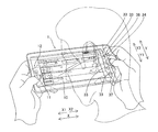
- FIG. 2 is a perspective view showing a state in which a frame and a liquid crystal display unit of the portable information display terminal shown in FIG. It is the perspective view which showed the state in which the transversal direction of the liquid crystal display part of the portable information display terminal shown in FIG. 1 and the up-down direction of a user's face substantially correspond.
- FIG. 2 is a perspective view showing a state in which a frame and a liquid crystal display unit of the portable information display terminal shown in FIG. It is the perspective view which showed the state in which the transversal direction of the liquid crystal display part of the portable information display terminal shown in FIG. 1 and the up-down direction of a user's face substantially correspond.
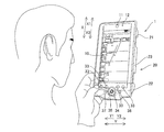
- FIG. 2 is a view showing a state in which the orientation of the user's face is inclined between about ⁇ 45 degrees and about +45 degrees with respect to the short direction of the liquid crystal display unit of the portable information display terminal shown in FIG. It is the perspective view which showed the state in which the longitudinal direction of the liquid crystal display part of the portable information display terminal shown in FIG. 1 and the up-down direction of a user's face correspond substantially.
- FIG. 2 is a view showing a state in which the orientation of the user's face is inclined between about ⁇ 45 degrees and about +45 degrees with respect to the longitudinal direction of the liquid crystal display section of the portable information display terminal shown in FIG.
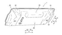
- a portable information display terminal 1 includes a liquid crystal display unit 10 (see FIG. 1) for displaying information, and a frame 20 on which the liquid crystal display unit 10 is provided. And is mainly composed.
- the liquid crystal display unit 10 is an example of the “display unit” in the present invention
- the frame 20 is an example of the “casing” in the present invention.
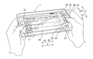
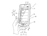
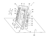
- the portable information display terminal 1 is configured to be usable in a state of being held by a user (see FIGS. 3 and 4), and in a state where the frame 20 and the liquid crystal display unit 10 are placed on the placement surface 100 (see FIG. 5), and the state in which the frame 20 and the liquid crystal display unit 10 are laid on the mounting surface 100 (see FIG. 6).
- the state held by the user is an example of the “predetermined use state” and the “third use state” of the present invention
- the state where the frame 20 and the liquid crystal display unit 10 are placed on the placement surface 100 is It is an example of the “first use state” of the present invention.
- the state where the frame 20 and the liquid crystal display unit 10 are laid on the mounting surface 100 is an example of the “second use state” of the present invention.
- the portable information display terminal 1 is configured to be connectable to the Internet, and is configured to be able to use streaming distribution reception and playback output functions, mail functions, video chat functions, and voice chat functions by connecting to the Internet. . Moreover, the portable information display terminal 1 is configured to be usable as a remote controller for a media player, a television device (not shown), etc., by shifting to the remote control mode even when not connected to the Internet. Moreover, the portable information display terminal 1 can display a calendar, a clock, etc. with a small-scale application software (gadget) in the state where the frame 20 and the liquid crystal display unit 10 are set up (see FIG. 5).
- a small-scale application software gadget
- the liquid crystal display unit 10 has a touch panel function, and can be operated according to an application program when the user presses the operation button 10 a displayed on the liquid crystal display unit 10. It is configured.
- a camera unit 11 is installed on the liquid crystal display unit 10 on the arrow X1 direction side.
- the camera unit 11 has a function of imaging the user's face, for example, when the portable information display terminal 1 is used while being held by the user.
- the camera unit 11 is an example of the “imaging unit” in the present invention.
- a microphone unit 12 is installed in the vicinity of the camera unit 11.
- the microphone unit 12 has a function of inputting voice during voice chat and video chat, for example.
- the frame 20 is made of resin.
- a plurality of protrusions 21, 22, and 23 are integrally provided on the surface of the frame 20 opposite to the surface on which the liquid crystal display unit 10 is provided.
- the protrusions 21 and 22 are provided in the vicinity of both ends in the longitudinal direction (X direction) of the frame 20 so as to extend in the short direction (Y direction) of the frame 20.
- the protrusions 21 (see FIG. 2) and 22 are respectively arranged from one end side (arrow Y1 direction side) in the short direction (Y direction) of the frame 20 to the other end side (arrow Y2). The thickness is gradually increased toward the direction side).
- the protrusions 21 and 22 are seen from the other side (arrow Y2 direction side) in the short direction of the frame 20 as viewed from the longitudinal direction of the frame 20 (arrow X1 direction and arrow X2 direction), respectively (arrow Y1). It is configured to have a wedge shape tapered toward the direction side.
- the portable information display terminal 1 is placed on the mounting surface 100 with the surfaces of the protrusions 21 and 22 on the arrow Y2 direction side down.
- the protrusions 21 and 22 can support the frame 20 in a state where the frame 20 and the liquid crystal display unit 10 are upright.
- the protrusions 21 (see FIG. 2) and 22 are arranged so that the frame 20 and the liquid crystal display unit 10 are laid at a predetermined angle ⁇ with respect to the mounting surface 100. Can be supported.
- the projections 21 and 22 are viewed from the user in the longitudinal direction (X direction) of the frame 20 and the liquid crystal display unit 10.
- the user can hold it horizontally with both hands.
- the protrusion 22 can be held with one hand (left hand) with the longitudinal direction (X direction) of the frame 20 and the liquid crystal display unit 10 in the vertical direction.
- the protrusion 23 is provided in the vicinity of the other end (the end in the arrow Y2 direction) in the short direction (Y direction) of the frame 20 and between the protrusions 21 and 22. ing. Inside the protrusion 23, a secondary battery (lithium ion battery) for supplying power to the portable information display terminal 1 is incorporated (stored).
- a secondary battery lithium ion battery
- infrared communication units 31 and 32 are built in the end surfaces on the other end side (arrow Y2 direction side) of the protrusions 21 and 22, respectively. These infrared communication units 31 and 32 are configured to emit infrared light including a predetermined signal (remote control signal) capable of operating a media player, a television device (not shown) and the like in a remote control mode to be described later. ing.
- a predetermined signal remote control signal
- various switches 33 for the information processing apparatus mode are provided in the longitudinal direction (X direction) portion of the liquid crystal display unit 10 on the arrow X2 direction side.
- the information processing device mode switches 33 are switches used in an information processing device mode for processing mail, video, voice chat, and the like.
- a four-way movement switch 34 selection switch
- a determination switch 35 is provided at the center of the four-way movement switch 34. The four-way movement switch 34 and the determination switch 35 are configured to be usable in both the remote control mode and the information processing apparatus mode, respectively.
- a remote control mode transition switch 36 capable of switching between the remote control mode and the information processing apparatus mode is provided on the arrow Y2 direction side of the four-way movement switch 34.
- an OSD-displayed operation screen on the display unit of a remote control operation target device (such as a television) in the remote control mode is used to return the current state to the previous state.
- a return function switch 37 is provided.
- connection unit 40 includes two USB connection units 41 and 42, an HDMI connection unit 43, an audio cable connection unit 44, and a power connector 45.
- the frame 20 of the portable information display terminal 1 is provided with a control unit (CPU) 51 that controls the portable information display terminal 1, a storage unit (memory) 52, and an inclination sensor 53. ing.
- the storage unit 52 stores an application program executed by the control unit 51.
- the tilt sensor 53 is an example of the “state detection sensor” in the present invention.
- the tilt sensor 53 has a function of acquiring the tilt of the frame 20 (see FIG. 1).
- the tilt sensor 53 is in a state where the frame 20 and the liquid crystal display unit 10 are used while being placed on the mounting surface 100 (hereinafter referred to as a standing state (see FIG. 5)), and the frame 20 and the liquid crystal display unit 10 are mounted.
- a state in which the frame 100 is laid on the surface 100 hereinafter referred to as a laid state (see FIG. 6)
- a hand-held state see FIGS. 3 and 4
- It is provided for detecting which state of use.
- the tilt sensor 53 is not only in a standing state (see FIG. 5), in a laid state (see FIG. 6) and in a hand-held state (see FIGS. 3 and 4), but also the frame 20 and the liquid crystal display unit 10 are placed on the mounting surface. It is configured to be able to detect a state (unused state) (see FIG. 8) that is faced to face 100.
- the control unit 51 can easily determine and identify each state based on the different inclinations of the frame 20 with respect to the mounting surface 100. Is possible.
- the tilt in a state where the frame 20 and the liquid crystal display unit 10 are used while standing on the mounting surface 100 is an example of the “first tilt” in the present invention, and the frame 20 and the liquid crystal display unit 10 are mounted on the mounting surface.
- the inclination in the state where the apparatus is laid down on 100 is an example of the “second inclination” in the present invention.
- the detection value detected by the tilt sensor 53 changes every detection time due to a slight movement of the user. It is possible to distinguish between a laid state and a lying state (non-use state). Further, the tilt sensor 53 is used in a vertical orientation in which the longitudinal direction of the frame 20 is used in the vertical direction (hereinafter, referred to as FIG. 4) even in the handheld state (see FIG. 3 and FIG. 4). )) And a horizontally used state in which the longitudinal direction of the frame 20 is used sideways (hereinafter referred to as a horizontally held state (refer to FIG. 3)). Further, as shown in FIGS. 3 and 4, in the vertically held state and the horizontally held state, the liquid crystal display unit 10 is rotated about 90 degrees, so that the tilt sensor 53 is different between the vertically held state and the horizontally held state. It is possible to easily identify and identify the inclination.
- the control unit 51 detects the use state of the frame 20 and the liquid crystal display unit 10 by the tilt sensor 53 or the detection result of the face down state (non-use state) and the face detection function of the camera unit 11. Based on the detection result of the user's face orientation detected by the above, the use state of the frame 20 and the liquid crystal display unit 10 or the face down state (non-use state) is determined and specified. .
- the control unit 51 is configured to perform control to switch the screen display direction of the liquid crystal display unit 10 based on the detection result of the tilt sensor 53 and the detection result of the user's face direction.
- the control unit 51 when the posture (state) of the portable information display terminal 1 is changed by the user, the control unit 51 is laid down based on the detection result by the tilt sensor 53 (see FIG. 5). It is configured to be able to identify and identify one of a state (see FIG. 6), a hand-held state (see FIGS. 3 and 4), and a face-down state (non-use state) (see FIG. 8). Then, when the control unit 51 determines and identifies the state of standing (see FIG. 5) or lying down (see FIG. 6) based on the detection result of the tilt sensor 53, the tilt sensor 53 is identified. The screen display orientation of the liquid crystal display unit 10 is switched in accordance with the detection result obtained by the method according to the standing state (see FIG.
- the control unit 51 is based on the detection result by the inclination sensor 53 when the inclination sensor 53 detects that the portable information display terminal 1 is not in the handheld state.
- the screen display direction of the liquid crystal display unit 10 is controlled to be switched.
- control unit 51 determines and identifies the hand-held state (see FIGS. 3 and 4) based on the detection result by the tilt sensor 53, the control unit 51 uses the hand-held state detected by the tilt sensor 53. In addition, priority is given to the detection result of the user's face orientation, and the screen display orientation corresponding to the user face orientation is switched. Specifically, as illustrated in FIGS. 9 and 10, the control unit 51 has a function of detecting the orientation of the user's face captured by the camera unit 11 using a face detection function. When it is determined that the vertical direction is substantially the same as the short direction (Y direction) of the liquid crystal display unit 10, the short direction (Y direction) of the liquid crystal display unit 10 is set to the vertical direction to display the screen. Is configured to display.
- the control unit 51 determines that the orientation of the user's face is between about ⁇ 45 degrees and about +45 degrees with respect to a reference line (dashed line) extending along the short direction (Y direction) of the liquid crystal display section 10 ( 10), the liquid crystal display unit 10 is configured to display the screen display by setting the short side direction (Y direction) to the vertical direction.
- the liquid crystal display unit 10 is configured to display a screen display by setting the longitudinal direction (X direction) of the display unit 10 in the vertical direction.
- control unit 51 determines that the orientation of the user's face is between about ⁇ 45 degrees and about +45 degrees with respect to a reference line (dashed line) extending along the longitudinal direction (X direction) of the liquid crystal display section 10 (FIG. 12).
- a reference line dashed line
- the longitudinal direction (X direction) of the liquid crystal display unit 10 is set to the vertical direction to display a screen display.
- the camera unit 11 is arranged outside the liquid crystal display unit 10 along a reference line extending along the longitudinal direction (X direction) of the liquid crystal display unit 10. That is, in the portable information display terminal 1, in particular, when the longitudinal direction (X direction) is set to the up and down direction, it is between about ⁇ 45 degrees and about +45 degrees in the left and right direction (Y direction) with respect to the camera unit 11. Even when the orientation of the user's face is inclined, the screen display is configured such that the vertical direction of the screen display corresponds to the longitudinal direction.
- control unit 51 is configured to automatically start an application program corresponding to the specified use state or to perform control to shift to the standby mode. Specifically, the control unit 51 is configured to start an application program that is not assumed to be operated by the user when it is identified that the control unit 51 is in the upright state (see FIG. 5). In addition, the control unit 51 is configured to activate an application program that is assumed to be operated by the user when it is specified that the user is in the laid state (see FIG. 6). In addition, the control unit 51 is configured to start an application program that is assumed to be operated by the user even when the handheld state (see FIGS. 3 and 4) is specified. The application program corresponding to the specified use state is set in advance by the user.
- control unit 51 determines whether or not the inclination value detected by the inclination sensor 53 is constantly changing in small increments, whereby the portable information display terminal 1 is placed on the placement surface 100 ( 5, 6, and 8) or a state of being gripped by the user (state of FIGS. 3 and 4).
- the control unit 51 determines that the portable information display terminal 1 is being held by the user.
- the control unit 51 is configured to determine that the portable information display terminal 1 is placed on the placement surface 100. Has been.
- control unit 51 is in a state in which the frame 20 and the liquid crystal display unit 10 are faced down so as to face the placement surface 100 by the inclination sensor 53 (non-use state) (see FIG. 8).
- the control unit 51 is configured not to start the application program used by the user, unlike in the use state (the standing state, the laying state, and the hand-held state).
- the control unit 51 when the tilt value in the hand-held state is detected by the tilt sensor 53, the control unit 51 detects the same tilt value as in the face-down state (non-use state) (see FIG. 8). Even in such a case, it is configured not to enter the standby mode.
- the control unit 51 is configured to perform control for causing the liquid crystal display unit 10 to display a screen display based on the detection result of the user's face orientation. That is, in a state where the user is holding the frame 20, the control unit 51 is in a standby state in any state including the case where the tilt of the face (unused state) is detected with respect to the frame 20. It is configured to perform control that does not shift to the mode.
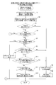
- step S1 the control unit 51 (see FIG. 7) recognizes (evaluates) the inclination value acquired from the inclination sensor 53, and the inclination value is stored in the storage unit 52.
- step S2 the portable information display terminal 1 is erected (see FIG. 5) and laid down (FIG. 6) based on the state of change between the stored past inclination value and the currently stored inclination value. (Refer to FIG. 8) and a hand-held state (refer to FIG. 3 and FIG. 4) are determined. That is, when the stored past inclination value and the currently stored inclination value change in small increments, it is determined that the hand is held.
- the It is determined as a state.
- the inclination value stored this time is within the range of the inclination value of the laying state, it is determined to be the laying down state, and the inclination value stored in the state where the inclination value stored this time is laid down (unused state). If it is within the range, it is determined to be in a face-down state (non-use state).
- step S3 the control unit 51 determines whether or not the determined state is changed from the state before the inclination value acquired by the inclination sensor 53 is changed (before the event occurs). If it is determined in step S3 that the determined state is not changed from the state before the inclination value acquired by the inclination sensor 53 is changed (before the event occurs), the process proceeds to step S4. In step S4, since the state is not changed, the application program is maintained as it is without changing the application program, and the process proceeds to step S5. In step S5, the display orientation displayed on the liquid crystal display unit 10 is also maintained without being changed, and the display orientation change and maintenance flow corresponding to the state of the portable information display terminal 1 is completed.
- step S6 the control unit 51 determines whether or not the changed state is a state in which the frame 20 is held and used by the user's hand (hand-held state (see FIGS. 3 and 4)). . If it is determined in step S6 that the changed state is the handheld state, the process proceeds to step S21 (see FIG. 14) described later. If it is determined in step S6 that the changed state is not a handheld state, the process proceeds to step S7.
- step S7 whether the state changed by the control unit 51 is a state in which the frame 20 and the liquid crystal display unit 10 face down so as to face the placement surface 100 (non-use state) (see FIG. 8). Is judged.
- step S7 if it is determined that the changed state is a cover-up state (non-use state), the process proceeds to step S8.
- step S8 the control unit 51 shifts to the standby mode, and the display orientation change and maintenance flow corresponding to the state of the portable information display terminal 1 ends.
- step S9 determines to the changed state is not a cover-up state (non-use state).
- step S6 the liquid crystal display unit 10 is based on the detection result by the tilt sensor 53 without starting the camera unit 11. Control for switching the screen display orientation is performed.
- step S9 the control unit 51 determines whether or not an application program corresponding to the changed state is set. That is, in step S9, it is determined whether or not an application program to be automatically activated for each of the standing state, the laying state, and the hand-held state is set by the user. If it is determined in step S9 that the application program corresponding to the changed state has not been set, the process proceeds to step S4 and step S5 described above, and the display orientation corresponding to the state of the portable information display terminal 1 The change and maintenance flow ends. If it is determined in step S9 that an application program corresponding to the changed state is set, the process proceeds to step S10.
- step S10 the control unit 51 determines whether the set application program is the same application program that is currently in use. If it is determined in step S10 that the set application program is the same application program as the currently used application program, there is no need to change the application program, so that the above-described steps S4 and S5 are performed. The display orientation change and maintenance flow corresponding to the state of the portable information display terminal 1 is completed. If it is determined in step S10 that the set application program is not the same application program as the currently used application program, the process proceeds to step S11.
- step S11 an application program set by the user corresponding to the changed state is activated, and the process proceeds to step S12.
- step S12 the display orientation corresponding to the state is changed or the display orientation is maintained, and the display orientation changing and maintaining flow corresponding to the state of the portable information display terminal 1 ends.
- the display orientation displayed on the liquid crystal display unit 10 is changed by being rotated 180 degrees.
- the display orientation displayed on the liquid crystal display unit 10 is changed by being rotated 90 degrees or 270 degrees.
- the display orientation displayed on the liquid crystal display unit 10 is maintained as it is without being changed.
- control unit 51 determines that the changed state is the handheld state in step S6 will be described in detail.
- step S21 when it is determined that the changed state in step S6 (see FIG. 13) is a handheld state, in step S21, the use state detection function by the tilt sensor 53 is maintained.
- the control unit 51 activates the camera unit 11. Then, the process proceeds to step S22.
- step S22 In the processing flow after step S22, even when the tilt sensor 53 detects a tilted state (unused state) with respect to the frame 20, the standby state as in step S8 (see FIG. 13) is performed. Control that switches the screen display orientation of the liquid crystal display unit 10 based on the detection result of the camera unit 11 is performed without shifting to the mode.
- step S22 the controller 51 determines whether or not the orientation of the user's face has been detected based on the data imaged by the camera unit 11. If it is determined in step S22 that the orientation of the user's face has been detected, the process proceeds to step S23.
- step S23 the control unit 51 changes or maintains the screen display displayed on the liquid crystal display unit 10 in the display direction corresponding to the orientation of the user's face, and the display direction corresponding to the state of the portable information display terminal 1.
- the change and maintenance flow ends. For example, when the standing state is changed to the hand-held state, the display orientation displayed on the liquid crystal display unit 10 is rotated by 180 degrees.
- the display orientation displayed on the liquid crystal display unit 10 is 90 degrees or 270 degrees. It is rotated. Further, when the state is changed from the laid state to the horizontally held state of the hand-held state, the display orientation displayed on the liquid crystal display unit 10 is maintained as it is without being changed.
- step S24 based on the inclination value detected by the inclination sensor 53 by the control unit 51, whether or not the detected inclination value has changed over a predetermined angle range from the previously detected inclination value. To be judged. That is, it is determined whether or not the user has moved the portable information display terminal 1 within a large angle range. If it is determined in step S24 that the detected tilt value has changed within the predetermined angle range from the previously detected tilt value, the process proceeds to step S25. In step S25, the screen display direction currently displayed on the liquid crystal display unit 10 is maintained without switching the screen display direction of the liquid crystal display unit 10, and the display corresponding to the state of the portable information display terminal 1 is performed. The direction change and maintenance flow ends.
- step S24 is executed. Proceed to S26.
- the control unit 51 uses the face detection function to detect the orientation of the user's face again.
- step S27 it is determined again whether or not the orientation of the user's face has been detected. If it is determined in step S27 that the orientation of the user's face has been detected, the process proceeds to step S23 described above.
- step S23 the screen display displayed on the liquid crystal display unit 10 is changed or maintained in the display direction corresponding to the orientation of the user's face, and the display orientation change and maintenance flow corresponding to the state of the portable information display terminal 1 is performed. Ends.
- step S27 If it is determined in step S27 that the orientation of the user's face cannot be detected, the process proceeds to step S28.
- step S28 the orientation of the screen display displayed on the liquid crystal display unit 10 is changed based on the inclination value detected by the inclination sensor 53 in a state where the detection function is maintained, and the portable information display terminal 1 is changed. The display orientation change and maintenance flow corresponding to the state is completed.
- the screen display orientation of the liquid crystal display unit 10 is switched based on the detection result of the user's face orientation detected by the face detection function and the detection result of the tilt sensor 53.
- the orientation of the user's face imaged by the camera unit 11 is changed. Even when it cannot be detected, it is possible to detect the state (posture) of the frame 20 by the inclination sensor 53 that detects the inclination of the frame 20. Thereby, even when the orientation of the user's face imaged by the camera unit 11 cannot be detected, the screen is displayed in an appropriate display orientation based on the state (posture) detected by the tilt sensor 53. Can do.
- the orientation of the user's face by the camera unit 11 is based on the detection result by the tilt sensor 53.
- the tilt sensor 53 determines the usage state of the frame 20 and the liquid crystal display unit 10 before the camera unit 11 is activated. It is possible to detect and determine whether it is necessary to activate the camera unit 11 according to the detection result by the tilt sensor 53.
- the orientation of the user's face is more than that of the use state detected by the tilt sensor 53.
- the screen display direction based on the detection result of the user's face direction and the screen display based on the tilt by the tilt sensor 53 are displayed.
- priority is given to the detection result of the face direction, so that the screen can be displayed in an orientation that more closely matches the actual usage mode. it can.
- the user's face is more than the use state detected by the tilt sensor 53.
- the tilt sensor Since it is difficult to determine how the user is viewing the screen from the detection result based on the inclination by 53, when the frame 20 is in a state of gripping with the hand, the orientation of the user's face is detected, By switching to the screen display orientation corresponding to the orientation of the user's face, the screen can be displayed in a more appropriate screen display orientation that matches the actual usage.
- the user's face orientation is the vertical direction of the liquid crystal display unit 10 (the Y direction in FIG. 10, FIG. 12).
- the liquid crystal display unit 10 is tilted within a predetermined angle range with respect to a reference line along the X direction of FIG. 10 and FIG. 12 (a dashed line shown on the liquid crystal display unit 10 in FIG. 12).
- a situation in which the orientation of the screen display is frequently switched by maintaining the orientation of the screen display without switching, so that the orientation of the user's face strictly reacts to a state where the orientation of the user's face does not completely match the vertical direction of the liquid crystal display unit 10 Can be avoided.
- the operability of the portable information display terminal 1 by the user can be improved by the amount that the frequent switching operation of the display screen is not performed.
- the predetermined angle range is configured as an angle range in which the orientation of the user's face is equally inclined at about 45 degrees in the left-right direction orthogonal to the reference line. Even if the orientation of the user's face is tilted in any of the left and right directions with respect to the reference line, it is possible to determine whether or not the screen display orientation can be switched with approximately the same sensitivity. Therefore, the operability of the portable information display terminal 1 can be made uniform without depending on the inclination direction of the face direction.
- the camera unit 11 is arranged outside the liquid crystal display unit 10 along the reference line, whereby the orientation of the user's face by the camera unit 11 is specified. Since the reference line along the vertical direction of 10 can be used as the center, the inclination direction of the user's face can be accurately detected.
- the tilt sensor 53 detects that the frame 20 is not in a use state (hand-held state) in which the frame 20 is used by hand
- the detection result by the tilt sensor 53 is displayed. Based on this, control for switching the screen display orientation of the liquid crystal display unit 10 is performed.
- the frame 20 is fixedly placed on the placement surface 100 or the like.
- the orientation of the liquid crystal display unit 10 and the orientation of the user's face when the user views the liquid crystal display unit 10 are constant.
- the detection result of the inclination sensor 53 is used without using the face detection function.
- the screen display direction of the liquid crystal display unit 10 the screen can be displayed in an appropriate display direction.
- the tilt sensor 53 when the tilt sensor 53 detects that the frame 20 is not being used by being held by hand, the tilt sensor 53 is not activated without starting the camera unit 11. Based on the detection result obtained by the above, control for switching the screen display orientation of the liquid crystal display unit 10 is performed. Thereby, since the operation
- the tilt sensor 53 when the tilt sensor 53 detects at least a hand-held state, priority is given to the detection result of the user's face direction, and the user's face direction is handled.
- the orientation of the screen display of the liquid crystal display unit 10 is switched to the orientation of the screen display, and when the tilt sensor 53 detects that the screen is in the upright state or the laying state, based on the detection result by the tilt sensor 53,
- the tilt sensor 53 By switching the screen display direction of the liquid crystal display unit 10, when the frame 20 is placed on the placement surface 100 in the upright state or in the laid state, the tilt sensor 53 causes an appropriate display direction. A screen can be displayed.
- the screen is displayed with an appropriate display orientation that matches the orientation of the user's face based on the detection result of the user's face orientation. Can do.
- the tilt sensor 53 detects that the frame 20 is not in a handheld state held by the user, and the liquid crystal display unit 10 is faced down so as to face the placement surface 100.
- the state shifts to the standby mode without using the face detection function, and is detected as being in a hand-held state by the inclination sensor 53 and is in a face-down state (non-use)
- a screen display based on the detection result of the user's face orientation is displayed on the liquid crystal display unit 10 without shifting to the standby mode.
- the mobile information display terminal 1 can save power by shifting to the standby mode.
- the tilt sensor 53 detects that the tilt is in the face down state (not in use)
- the user uses the portable information display terminal 1.
- the screen can be displayed in the display orientation.
- the frame 20 and the liquid crystal display by the tilt sensor 53 are displayed.
- the detection function can be used even under a situation where the camera unit 11 cannot detect the orientation of the user's face when the frame 20 is gripped by the user. Since the use state (posture) of the frame 20 and the liquid crystal display unit 10 can be immediately detected using the tilt sensor 53 in which the screen is maintained, the operation of displaying the screen in an appropriate display direction can be reliably performed. .
- the outer shape of the frame 20 that can be installed on the mounting surface 100 so that the inclination when the frame 20 is upright and the inclination when the frame 20 is laid down are different from each other. Since the frame 20 can be installed on the mounting surface 100 with different inclinations between the standing state and the laying state based on the outer shape of the frame 20, the detection by the inclination sensor 53 can be performed. Based on the result, it is possible to easily discriminate between the standing state and the laying state, and to display the screen in an appropriate display orientation corresponding to the standing state and the laying state.
- the standing state is based on the inclination of the frame 20 that is different from the standing state based on the outer shape of the frame 20 acquired by the tilt sensor 53 by 90 degrees or more.
- the tilt sensor 53 when it is determined that the tilt value detected this time is within a predetermined angle range from the previously detected tilt value, the screen display orientation of the liquid crystal display unit 10 is maintained without being switched.
- the inclination is changed to the previous time. Since the inclination does not change greatly from the inclination when the value is detected, it is considered that the relative positional relationship between the user and the portable information display terminal 1 does not change significantly.
- the screen by maintaining the screen display orientation of the liquid crystal display unit 10 without switching, the screen can be displayed in an appropriate display orientation that matches the orientation of the user's face.
- the tilt sensor 53 when it is detected that the tilt value detected this time has changed from the previously detected tilt value beyond a predetermined angle range, the face detection function of the camera unit 11 detects the orientation of the user's face. It is configured to fix.
- the screen is displayed with an appropriate display orientation that matches the orientation of the user's face based on the detection result of the orientation of the user's face that has been detected again. Can be displayed.
- the liquid crystal display is performed based on the detection result by the tilt sensor 53. Even when the camera unit 11 cannot re-detect the face orientation of the user when the frame 20 is held by the user, the screen display orientation of the unit 10 is switched. Since the use state (posture) of the frame 20 and the liquid crystal display unit 10 can be detected immediately using the tilt sensor 53, the operation of displaying the screen in an appropriate display direction can be performed without interruption.
- the inclination angle before the usage state stored in the storage unit (memory) 52 is changed and the inclination after the usage state stored in the storage unit 52 is changed.
- the use state is changed by discriminating and specifying the standing state and the laying state by comparing the angle, and by identifying and specifying the use state in which the frame 20 is gripped by hand. Based on the change in the tilt angle before and after, the above three usage states of the portable information display terminal 1 can be reliably discriminated and specified.
- the use state in which the frame 20 is gripped by hand is determined.
- the change in the inclination angle over time can be determined by determining and specifying the standing state or the laying state.
- the example in which the face detection function is used to detect the orientation of the user's face is shown only when the frame is in a hand-held state in which the user's hand is used. Not limited to. Even when the frame is in a state other than the hand-held state where the frame is held by the user's hand, the face detection function may be used to detect the user's face orientation.
- the tilt sensor 53 is used as an example of the state detection sensor of the present invention.
- the present invention is not limited to this.
- a sensor other than an inclination sensor such as an acceleration sensor may be used to detect the state of the portable information display terminal 1.
- the tilt sensor 53 is used in a state where the frame 20 and the liquid crystal display unit 10 are used while being placed on the mounting surface, and the frame 20 and the liquid crystal display unit 10 are used while lying on the mounting surface 100. Only a state in which the frame 20 is held and used by hand, or a state in which the frame 20 and the liquid crystal display unit 10 are faced down so as to face the mounting surface 100 (non-use state).
- the present invention is not limited to this.
- the portable information display terminal is hooked and held on the wall, so that it is standing, lying, handheld and lying You may make it detect states other than the state (non-use state).
- the tilt sensor 53 is used in a state where the frame 20 and the liquid crystal display unit 10 are used while being placed on the mounting surface 100, and the frame 20 and the liquid crystal display unit 10 are used while lying on the mounting surface 100.
- the frame 20 is configured in an outer shape that can be placed in a lying state
- the present invention is not limited to this.
- the tilt sensor 53 stands in a state where the frame 20 and the liquid crystal display unit 10 are used while being placed on the mounting surface 100, and the frame 20 and the liquid crystal display unit 10. May be placed on the placement surface 100 in a laid state for use.
- remote control of a control target device is performed by emitting infrared light including a remote control signal to the control target device in the remote control mode
- the present invention is not limited thereto.
- the remote control of the device to be controlled may be performed by using a wireless communication standard such as Bluetooth (registered trademark) or Zigbee (registered trademark).
- the processing operation of the control unit is described in an event-driven manner at the start, and the processing operation of the start transition is described using a flowchart described in a flow-driven manner. It is not limited to this.
- the processing operation of the control unit may be performed by a complete event drive type, may be performed by a complete flow drive type, or may be performed in parallel processing.
Landscapes
- Engineering & Computer Science (AREA)
- Theoretical Computer Science (AREA)
- General Engineering & Computer Science (AREA)
- Physics & Mathematics (AREA)
- General Physics & Mathematics (AREA)
- Computer Hardware Design (AREA)
- Human Computer Interaction (AREA)
- Multimedia (AREA)
- Signal Processing (AREA)
- Social Psychology (AREA)
- General Health & Medical Sciences (AREA)
- Health & Medical Sciences (AREA)
- Databases & Information Systems (AREA)
- Computer Networks & Wireless Communication (AREA)
- Controls And Circuits For Display Device (AREA)
- Telephone Function (AREA)
Abstract
Description
Claims (20)
- 情報を表示する表示部(10)と、
前記表示部が表面に設けられる筐体(20)と、
前記筐体の傾きを検知することにより前記筐体および前記表示部の少なくとも使用状態を検出するための状態検出センサ(53)と、
ユーザの顔を撮像可能な撮像部(11)と、
前記撮像部により撮像されたユーザの顔のデータに基づいて顔検出機能により顔の向きの検出を行うとともに、顔の向きの検出結果と、前記状態検出センサによる検出結果とに基づいて、前記表示部の画面表示の向きを切り替える制御を行う制御部(51)とを備えた、携帯情報表示端末(1)。 - 前記制御部は、前記状態検出センサにより前記筐体および前記表示部の使用状態を検出した後に、前記状態検出センサによる検出結果に基づいて、前記撮像部による前記ユーザの顔の向きの検出を行うか否かを判別する制御を行うように構成されている、請求項1に記載の携帯情報表示端末。
- 前記制御部は、前記状態検出センサにより所定の使用状態が検出された場合には、前記状態検出センサにより検出された使用状態よりも、前記ユーザの顔の向きの検出結果を優先させて、ユーザの顔の向きに対応する画面表示の向きに切り替える制御を行うように構成されている、請求項1に記載の携帯情報表示端末。
- 前記所定の使用状態は、前記筐体を手で把持して使用する使用状態であり、
前記制御部は、前記筐体を手で把持して使用する使用状態が検出された場合に、前記状態検出センサにより検出された使用状態よりも、前記ユーザの顔の向きの検出結果を優先させて、ユーザの顔の向きに対応する画面表示の向きに切り替える制御を行うように構成されている、請求項3に記載の携帯情報表示端末。 - 前記制御部は、前記撮像部により撮像された前記ユーザの顔のデータに基づいて、前記ユーザの顔の向きが前記表示部の上下方向に沿った基準線に対して所定の角度範囲以内で傾斜していると判断した場合には、前記表示部の画面表示の向きを切り替えずに維持する制御を行うように構成されている、請求項4に記載の携帯情報表示端末。
- 前記所定の角度範囲は、前記ユーザの顔の向きが前記基準線に対して直交する左右方向に略等しく傾けられた角度範囲である、請求項5に記載の携帯情報表示端末。
- 前記撮像部は、前記基準線に沿った前記表示部の外側に配置されている、請求項6に記載の携帯情報表示端末。
- 前記制御部は、前記状態検出センサにより前記筐体を手で把持して使用する使用状態ではないことが検出された場合には、前記状態検出センサによる検出結果に基づいて、前記表示部の画面表示の向きを切り替える制御を行うように構成されている、請求項4に記載の携帯情報表示端末。
- 前記制御部は、前記状態検出センサにより前記筐体を手で把持して使用する使用状態ではないことが検出された場合には、前記撮像部を起動することなく前記状態検出センサによる検出結果に基づいて、前記表示部の画面表示の向きを切り替える制御を行うように構成されている、請求項8に記載の携帯情報表示端末。
- 前記状態検出センサは、前記筐体の傾きを検知することにより、前記筐体および前記表示部を載置面に立てて使用する第1の使用状態と、前記筐体および前記表示部を載置面に寝かせて使用する第2の使用状態と、前記所定の使用状態としての前記筐体を手で把持して使用する第3の使用状態とのいずれの使用状態であるかを検出するために設けられており、
前記制御部は、前記状態検出センサにより少なくとも前記第3の使用状態であることが検出された場合に、前記ユーザの顔の向きの検出結果を優先させて、ユーザの顔の向きに対応する画面表示の向きに切り替えるとともに、前記状態検出センサにより前記第1の使用状態または前記第2の使用状態であることが検出された場合には、前記状態検出センサによる検出結果に基づいて、前記表示部の画面表示の向きを切り替える制御を行うように構成されている、請求項3に記載の携帯情報表示端末。 - 前記状態検出センサは、前記所定の使用状態に加えて、少なくとも前記表示部が載置面に対向するように伏せた状態を検出するように構成されており、
前記制御部は、前記状態検出センサにより前記筐体がユーザにより把持された前記所定の使用状態ではないと検出され、かつ、前記表示部が載置面に対向するように伏せた状態の傾きが検出された場合に、前記顔検出機能を使用せずにスタンバイモードに移行するとともに、前記状態検出センサによりユーザにより前記筐体が把持された前記所定の使用状態であると検出され、かつ、前記表示部が載置面に対向するように伏せた状態の傾きが検出された場合に、前記スタンバイモードに移行せずに前記ユーザの顔の向きの検出結果に基づく画面表示を前記表示部に表示させる制御を行うように構成されている、請求項3に記載の携帯情報表示端末。 - 前記制御部は、前記スタンバイモードに移行せずに前記ユーザの顔の向きの検出結果に基づく画面表示を前記表示部に表示させる制御を行う際、前記状態検出センサによる前記筐体および前記表示部の使用状態を検出する機能を維持する制御を行うように構成されている、請求項11に記載の携帯情報表示端末。
- 前記状態検出センサは、前記筐体の傾きを検知することにより、少なくとも前記筐体および前記表示部を載置面に立てて使用する第1の使用状態と、前記筐体および前記表示部を載置面に寝かせて使用する第2の使用状態と、前記所定の使用状態としての前記筐体を手で把持して使用する第3の使用状態とのいずれの使用状態であるかを検出するために設けられており、
前記筺体は、前記第1の使用状態での第1の傾きと、前記第2の使用状態での第2の傾きとが、互いに異なる傾きになるように載置面に設置可能な外形形状を有するように構成されている、請求項3に記載の携帯情報表示端末。 - 前記筺体は、前記第1の傾きと前記第2の傾きとが、相対的に90度以上異なるように構成されており、
前記制御部は、前記状態検出センサにより取得される前記筐体の外形形状に基づく前記第1の使用状態と前記第2の使用状態との前記90度以上異なる前記筺体の傾きに基づいて、前記第1の使用状態と前記第2の使用状態とを判別して特定可能に構成されている、請求項13に記載の携帯情報表示端末。 - 前記制御部は、前記状態検出センサにより前記筐体を手で把持して使用する使用状態が検出された際に、前記撮像部により撮像されたユーザの顔データからユーザの顔の向きを検出できない場合において、前記状態検出センサにより今回検出された傾き値が前回に検出された傾き値から所定の角度範囲内に収まっていると判断した場合には、前記表示部の画面表示の向きを切り替えずに維持する制御を行うように構成されている、請求項1に記載の携帯情報表示端末。
- 前記制御部は、前記撮像部により撮像されたユーザの顔データからユーザの顔の向きを検出できない場合において、前記状態検出センサにより今回検出された傾き値が前回に検出された傾き値から所定の角度範囲を超えて変化していると検出された場合には、前記顔検出機能によりユーザの顔の向きを検出し直す制御を行うように構成されている、請求項15に記載の携帯情報表示端末。
- 前記制御部は、前記顔検出機能により前記ユーザの顔の向きを検出する際に、前記状態検出センサによる前記筐体および前記表示部の使用状態を検出する機能を維持する制御を行うように構成されており、
前記制御部は、前記顔検出機能により前記ユーザの顔の向きを検出し直す制御を行った結果、前記ユーザの顔の向きを検出できないと判断した際、前記状態検出センサによる検出結果に基づいて、前記表示部の画面表示の向きを切り替える制御を行うように構成されている、請求項16に記載の携帯情報表示端末。 - 前記状態検出センサにより検出された傾き角度を記憶する記憶部(52)をさらに備え、
前記状態検出センサは、前記筐体の傾きを検知することにより、少なくとも前記筐体および前記表示部を載置面に立てて使用する第1の使用状態と、前記筐体および前記表示部を載置面に寝かせて使用する第2の使用状態と、前記所定の使用状態としての前記筐体を手で把持して使用する第3の使用状態とのいずれの使用状態であるかを検出するために設けられており、
前記制御部は、前記記憶部に記憶された使用状態が変更される前の傾き角度と、前記記憶部に記憶された使用状態が変更された後の傾き角度とを比較することにより、前記第1の使用状態および前記第2の使用状態を判別して特定するとともに、前記筐体を手で把持して使用する前記第3の使用状態を判別して特定するように構成されている、請求項1に記載の携帯情報表示端末。 - 前記制御部は、前記状態検出センサにより検出された前記傾き角度が所定の範囲内で時間とともに変化する場合に、前記筐体を手で把持して使用する前記第3の使用状態を判別して特定するとともに、前記状態検出センサにより検出された前記傾き角度が前記所定の範囲内で時間とともに変化しない場合に、前記第1の使用状態または前記第2の使用状態を判別して特定するように構成されている、請求項18に記載の携帯情報表示端末。
- 前記状態検出センサは、傾きセンサを含む、請求項1に記載の携帯情報表示端末。
Priority Applications (2)
| Application Number | Priority Date | Filing Date | Title |
|---|---|---|---|
| KR1020127027913A KR20130139746A (ko) | 2011-04-06 | 2011-04-06 | 휴대 정보 표시 단말기 |
| PCT/JP2011/058737 WO2012137327A1 (ja) | 2011-04-06 | 2011-04-06 | 携帯情報表示端末 |
Applications Claiming Priority (1)
| Application Number | Priority Date | Filing Date | Title |
|---|---|---|---|
| PCT/JP2011/058737 WO2012137327A1 (ja) | 2011-04-06 | 2011-04-06 | 携帯情報表示端末 |
Publications (1)
| Publication Number | Publication Date |
|---|---|
| WO2012137327A1 true WO2012137327A1 (ja) | 2012-10-11 |
Family
ID=46968763
Family Applications (1)
| Application Number | Title | Priority Date | Filing Date |
|---|---|---|---|
| PCT/JP2011/058737 Ceased WO2012137327A1 (ja) | 2011-04-06 | 2011-04-06 | 携帯情報表示端末 |
Country Status (2)
| Country | Link |
|---|---|
| KR (1) | KR20130139746A (ja) |
| WO (1) | WO2012137327A1 (ja) |
Cited By (3)
| Publication number | Priority date | Publication date | Assignee | Title |
|---|---|---|---|---|
| WO2015101126A1 (zh) * | 2013-12-31 | 2015-07-09 | 华为技术有限公司 | 一种在视频通话中适应屏幕方向切换的方法和装置 |
| JP2018156673A (ja) * | 2013-03-11 | 2018-10-04 | ソニー株式会社 | 端末装置、端末装置の制御方法およびプログラム |
| CN115482568A (zh) * | 2021-05-31 | 2022-12-16 | 联想(新加坡)私人有限公司 | 电子设备以及控制方法 |
Citations (5)
| Publication number | Priority date | Publication date | Assignee | Title |
|---|---|---|---|---|
| JP2005004210A (ja) * | 2003-06-14 | 2005-01-06 | Lg Electronics Inc | 移動通信端末機の画像傾き自動補正装置及びその方法 |
| JP2005100084A (ja) * | 2003-09-25 | 2005-04-14 | Toshiba Corp | 画像処理装置及び方法 |
| JP2006267456A (ja) * | 2005-03-23 | 2006-10-05 | Casio Hitachi Mobile Communications Co Ltd | 画像処理装置、その画像処理方法及びプログラム |
| JP2009049512A (ja) * | 2007-08-14 | 2009-03-05 | Toshiba Corp | 画面表示処理装置および方法 |
| JP2011034029A (ja) * | 2009-08-06 | 2011-02-17 | Nec Casio Mobile Communications Ltd | 電子機器 |
-
2011
- 2011-04-06 WO PCT/JP2011/058737 patent/WO2012137327A1/ja not_active Ceased
- 2011-04-06 KR KR1020127027913A patent/KR20130139746A/ko not_active Withdrawn
Patent Citations (5)
| Publication number | Priority date | Publication date | Assignee | Title |
|---|---|---|---|---|
| JP2005004210A (ja) * | 2003-06-14 | 2005-01-06 | Lg Electronics Inc | 移動通信端末機の画像傾き自動補正装置及びその方法 |
| JP2005100084A (ja) * | 2003-09-25 | 2005-04-14 | Toshiba Corp | 画像処理装置及び方法 |
| JP2006267456A (ja) * | 2005-03-23 | 2006-10-05 | Casio Hitachi Mobile Communications Co Ltd | 画像処理装置、その画像処理方法及びプログラム |
| JP2009049512A (ja) * | 2007-08-14 | 2009-03-05 | Toshiba Corp | 画面表示処理装置および方法 |
| JP2011034029A (ja) * | 2009-08-06 | 2011-02-17 | Nec Casio Mobile Communications Ltd | 電子機器 |
Cited By (3)
| Publication number | Priority date | Publication date | Assignee | Title |
|---|---|---|---|---|
| JP2018156673A (ja) * | 2013-03-11 | 2018-10-04 | ソニー株式会社 | 端末装置、端末装置の制御方法およびプログラム |
| WO2015101126A1 (zh) * | 2013-12-31 | 2015-07-09 | 华为技术有限公司 | 一种在视频通话中适应屏幕方向切换的方法和装置 |
| CN115482568A (zh) * | 2021-05-31 | 2022-12-16 | 联想(新加坡)私人有限公司 | 电子设备以及控制方法 |
Also Published As
| Publication number | Publication date |
|---|---|
| KR20130139746A (ko) | 2013-12-23 |
Similar Documents
| Publication | Publication Date | Title |
|---|---|---|
| JP5440334B2 (ja) | 携帯情報表示端末 | |
| JP5625462B2 (ja) | 携帯情報表示端末 | |
| EP3115868B1 (en) | Camera-based orientation fix from portrait to landscape | |
| KR101818573B1 (ko) | 얼굴 인식을 이용한 보기모드 표시 방법 및 장치 | |
| US9998665B2 (en) | Camera mode selection based on context | |
| WO2011125995A1 (ja) | 携帯情報表示端末 | |
| JP5445285B2 (ja) | 携帯情報表示端末 | |
| EP3182695A2 (en) | Mobile terminal and method for controlling the same | |
| KR102184122B1 (ko) | 화면 표시 방법, 장치, 프로그램 및 저장매체 | |
| WO2012120799A1 (ja) | 表示装置及び表示方向切替方法 | |
| KR20090101733A (ko) | 휴대 단말기 및 그의 얼굴 인식을 이용한 표시정보의 표시방법 | |
| KR20170138279A (ko) | 이동 단말기 및 그 제어방법 | |
| US20110050477A1 (en) | Electronic apparatus, control method thereof, remote control apparatus, and control method thereof | |
| JP2011141330A (ja) | 携帯情報表示端末 | |
| US11947757B2 (en) | Personal digital assistant | |
| KR20150122362A (ko) | 이동 단말기 | |
| CN104123075A (zh) | 控制终端的方法及装置 | |
| KR20130139746A (ko) | 휴대 정보 표시 단말기 | |
| KR20140117184A (ko) | 디스플레이 장치 및 이를 제어하는 원격 제어 장치 | |
| US20110021252A1 (en) | Portable communication apparatus with a user mode switching function | |
| KR20130119223A (ko) | 모바일 기기 및 그 동작 방법 | |
| WO2012018178A2 (ko) | 입체 메인화면이 표시되는 휴대단말기 | |
| KR101782476B1 (ko) | 사용자 시선 기반 디스플레이 출력 자동 회전 방법 |
Legal Events
| Date | Code | Title | Description |
|---|---|---|---|
| ENP | Entry into the national phase |
Ref document number: 20127027913 Country of ref document: KR Kind code of ref document: A |
|
| 121 | Ep: the epo has been informed by wipo that ep was designated in this application |
Ref document number: 11863058 Country of ref document: EP Kind code of ref document: A1 |
|
| NENP | Non-entry into the national phase |
Ref country code: DE |
|
| 122 | Ep: pct application non-entry in european phase |
Ref document number: 11863058 Country of ref document: EP Kind code of ref document: A1 |
|
| NENP | Non-entry into the national phase |
Ref country code: JP |