WO2012137285A1 - Presence detection system, presence detection method, and program - Google Patents
Presence detection system, presence detection method, and program Download PDFInfo
- Publication number
- WO2012137285A1 WO2012137285A1 PCT/JP2011/058528 JP2011058528W WO2012137285A1 WO 2012137285 A1 WO2012137285 A1 WO 2012137285A1 JP 2011058528 W JP2011058528 W JP 2011058528W WO 2012137285 A1 WO2012137285 A1 WO 2012137285A1
- Authority
- WO
- WIPO (PCT)
- Prior art keywords
- reception level
- person
- receiver
- interval
- determination unit
- Prior art date
Links
Images


Classifications
-
- G—PHYSICS
- G01—MEASURING; TESTING
- G01S—RADIO DIRECTION-FINDING; RADIO NAVIGATION; DETERMINING DISTANCE OR VELOCITY BY USE OF RADIO WAVES; LOCATING OR PRESENCE-DETECTING BY USE OF THE REFLECTION OR RERADIATION OF RADIO WAVES; ANALOGOUS ARRANGEMENTS USING OTHER WAVES
- G01S13/00—Systems using the reflection or reradiation of radio waves, e.g. radar systems; Analogous systems using reflection or reradiation of waves whose nature or wavelength is irrelevant or unspecified
- G01S13/02—Systems using reflection of radio waves, e.g. primary radar systems; Analogous systems
- G01S13/04—Systems determining presence of a target
-
- G—PHYSICS
- G01—MEASURING; TESTING
- G01S—RADIO DIRECTION-FINDING; RADIO NAVIGATION; DETERMINING DISTANCE OR VELOCITY BY USE OF RADIO WAVES; LOCATING OR PRESENCE-DETECTING BY USE OF THE REFLECTION OR RERADIATION OF RADIO WAVES; ANALOGOUS ARRANGEMENTS USING OTHER WAVES
- G01S13/00—Systems using the reflection or reradiation of radio waves, e.g. radar systems; Analogous systems using reflection or reradiation of waves whose nature or wavelength is irrelevant or unspecified
- G01S13/003—Bistatic radar systems; Multistatic radar systems
-
- G—PHYSICS
- G08—SIGNALLING
- G08B—SIGNALLING OR CALLING SYSTEMS; ORDER TELEGRAPHS; ALARM SYSTEMS
- G08B21/00—Alarms responsive to a single specified undesired or abnormal condition and not otherwise provided for
- G08B21/18—Status alarms
- G08B21/22—Status alarms responsive to presence or absence of persons
-
- G—PHYSICS
- G01—MEASURING; TESTING
- G01V—GEOPHYSICS; GRAVITATIONAL MEASUREMENTS; DETECTING MASSES OR OBJECTS; TAGS
- G01V8/00—Prospecting or detecting by optical means
- G01V8/10—Detecting, e.g. by using light barriers
- G01V8/20—Detecting, e.g. by using light barriers using multiple transmitters or receivers
Definitions
- the present invention relates to a location detection system, a location detection method, and a program for detecting whether or not a person is present in a predetermined space.
- a microwave with high straightness such as 10.5 GHz
- a system for detecting the presence or absence of a person by directly irradiating the human body and receiving a reflected wave has been proposed.
- a microwave is used, a dedicated transmitter and receiver are required, and the entire system becomes expensive.
- the detection range is limited only to the direction in which the device emits the microwave. For this reason, this system is not suitable for applications such as detecting the presence of the entire room.
- a human behavior detection system uses radio waves transmitted from a wireless system that provides services with constant transmission power, such as TV broadcast waves, as a transmission source.
- This system uses the principle that the reception level of radio waves varies according to changes in the indoor multipath environment caused by the movement of a person, and detects the person's location by constantly detecting the fluctuation range of the reception level of radio waves. .
- a dedicated location detection system can be realized using a wireless communication device installed indoors for other purposes without requiring dedicated hardware.
- this system uses not only the radio wave transmitted directly from the transmitter to the receiver but also the reflected wave propagating throughout the room, it is possible to detect the presence of a wide room.
- the transmission function and the reception function in the located area detection system be mounted on battery-powered equipment such as a home appliance remote control and sensor equipment. This is because if these functions are installed in the remote control of the home appliance, it becomes easy to control the home appliance based on the location detection information.
- the present invention has been made in view of the above circumstances, and provides a located area detection system, a located area detection method, and a program that can easily and widely detect the person's area while reducing power consumption. For the purpose.
- a location detection system includes a transmitter that transmits a multipath radio signal in a predetermined space, and a location of a person by receiving the transmitted radio signal. And a receiver for detection.
- the first determination unit determines whether or not there is a change in the presence / absence state of the person based on the reception level of the radio signal received intermittently at the first interval.
- the second determination unit varies the reception level of the radio signal received at a second interval shorter than the first interval. Based on the above, the presence / absence of the person is determined.
- the interval for receiving the radio signal is shortened to be in the service area. Receives detection signals continuously. This eliminates the need to constantly receive a radio signal, so that it is possible to easily and widely detect the person's location while reducing power consumption.
- FIG. 1 It is a schematic diagram which shows schematic structure of the located area detection system which concerns on Embodiment 1 of this invention. It is a block diagram which shows the structure of the receiver of FIG. It is a graph which shows a reception level. 3 is a flowchart (part 1) illustrating an operation of the receiver of FIG. 6 is a flowchart (part 2) illustrating an operation of the receiver of FIG. It is a schematic diagram which shows schematic structure of the located area detection system which concerns on Embodiment 2 of this invention. It is a block diagram which shows the structure of the receiver of FIG.
- Embodiment 1 FIG. First, a first embodiment of the present invention will be described.
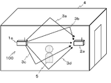
- FIG. 1 shows the configuration of a location detection system 100 according to Embodiment 1 of the present invention.
- the located area detection system 100 includes a transmitter 1a and a receiver 2a.
- the transmitter 1a transmits a location detection signal that is a multipath radio signal.
- the receiver 2a receives the transmitted area detection signal and detects the person's area. Both the transmitter 1a and the receiver 2a are installed in the in-zone detection area 4 as a predetermined space.
- the transmitter 1a is, for example, a wireless LAN (Local Area Network) base station or a home controller, and periodically transmits a beacon signal.
- the transmitter 1a can be used as long as it periodically transmits radio waves with a constant transmission output. For example, a broadcast wave of television or radio may be received and transferred into the in-zone detection area 4.
- the in-zone detection area 4 in which the transmitter 1a and the transmitter 2a are arranged is a predetermined space in a range where the person 5 enters and exits and the person 5 is detected.
- the location detection area 4 may be, for example, a single room or may extend over a plurality of rooms.
- the radio wave transmitted from the transmitter 1a is repeatedly reflected, transmitted, and diffracted by a wall surface, a ceiling, a floor in the in-zone detection area 4, or a fixture arranged in the in-zone detection area 4, for example, a propagation path
- the signal reaches the receiver 2a as a multipath radio signal via 3a, 3b, 3c, 3d and the like.
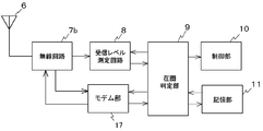
- FIG. 2 shows the configuration of the receiver 2a.
- the receiver 2 a includes an antenna 6, a radio circuit 7 a, a reception level measurement circuit 8, a located area determination unit 9, a control unit 10, and a storage unit 11.
- the antenna 6 receives a multipath radio signal transmitted from the transmitter 1a.
- the antenna 6 is an antenna with a small directivity, such as a dipole antenna, in order to facilitate reception of multipath radio signals.
- the radio signal received by the antenna 6 is input to the radio circuit 7a.
- the radio circuit 7a includes, for example, a filter that limits the band of the radio signal, an LNP (Low Noise Amp) that amplifies the radio signal, a mixer that converts the radio signal into an IF (Intermediate Frequency) stage, and the like.
- the output of the radio circuit 7a is input to the reception level measurement circuit 8.
- the reception level measurement circuit 8 measures the reception level of the radio signal based on the output of the radio circuit 7a.
- the reception level measured by the reception level measurement circuit 8 is output to the in-zone determination unit 9.
- the in-zone determination unit 9 functions as a first determination unit and a second determination unit.
- the location determination unit 9 determines whether or not the presence / absence state of the person 5 has changed based on the reception level of the radio signal intermittently received at the first interval (location detection interval T1). judge.
- the located area determination unit 9 receives the radio signal received at the located area detection interval T2 as the second interval shorter than the located area detection interval T1. Based on the variation in the reception level, the presence / absence of the person 5 is determined.
- the control unit 10 performs overall control of the entire receiver 2a.
- the control unit 10 controls the timing for operating the radio circuit 7a and the reception level measurement circuit 8. That is, the control unit 10 switches the timing at which the radio circuit 7a and the reception level measurement circuit 8 operate between the first reception interval and the second reception interval according to the determination result of the in-zone determination unit 9. .
- the storage unit 11 stores data used for determination by the in-zone determination unit 9, determination results, and the like.
- the located area determination unit 9 and the control unit 10 are, for example, microcomputers, and each function is realized by the CPU executing a program stored in the memory.
- the storage unit 11 includes, for example, a flash memory or a RAM (Random Access Memory).
- the transmitter 1a When the transmitter 1a starts operation, the transmitter 1a periodically transmits a beacon signal.
- a beacon signal For example, when the transmitter 1a is a wireless LAN base station, beacon signals are generally transmitted at intervals of about 100 ms.
- the beacon signal transmitted from the transmitter 1a reaches the receiver 2a via the propagation paths 3a, 3b, 3c, 3d and the like.
- the reception level at the receiver 2a is stable and becomes a substantially constant value.
- any of the propagation paths 3 a, 3 b, 3 c, 3 d, etc. is blocked or reflected by the person 5, so that the reception level at the receiver 2 a is lowered. It becomes larger than necessary or fluctuates according to the movement of the person 5.
- the receiver 2a parameters relating to the operation of the receiver 2a are set in advance.
- the setting of the receiver 2a will be described with reference to FIG.
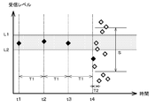
- the upper limit value and the lower limit value of the fluctuation range of the reception level when no person is present are set in the storage unit 11 of the receiver 2a.
- the difference between the upper limit value and the lower limit value is a value of about 5 dB to 10 dB, although it depends on the environment where the in-zone detection system 100 is installed.
- the median reception level when the person is absent is adjusted using the measurement result when the receiver 2a determines that the person is absent.
- the control unit 10 sets the average value of the reception levels of radio signals when a person is absent for a predetermined number of times as the median value of the reception levels.
- the upper limit value and the lower limit value can be updated based on the measurement result when it is determined that the person is absent.
- the in-zone detection interval T1 is set according to the device to be controlled.
- the in-zone detection interval T1 is set to an interval of several minutes in a low-urgency application in which the operation of home appliances such as an air conditioner is stopped in the absence.
- the operation of the receiver 2a is different depending on whether the previous presence detection result in the receiver 2a is determined to be present or not. First, the operation when it is determined that the previous location detection result is absent will be described with reference to FIGS. 3 and 4.
- FIG. 3 shows an example of the measurement result of the reception level determined by the location determination unit 9 when it is determined that the previous location detection result is absent.
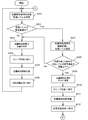
- FIG. 4 shows a flowchart showing processing when it is determined that the previous location detection result in the receiver 2a is absent.
- the reception level measurement circuit 8 receives the in-zone detection signal transmitted by the transmitter 1a once and measures the reception level (step S101).
- the in-zone detection signal received by the antenna 6 is input to the reception level measurement circuit 8 via the radio circuit 7a.
- the reception level measurement circuit 8 measures the reception level of the received beacon signal.
- the measured reception level is input to the in-zone determination unit 9.
- the area determination unit 9 determines whether the reception level of the received area detection signal is equal to or lower than the upper limit L1 and lower limit L2 of the fluctuation range of the reception level when no person is present, that is, within the set range. It is determined whether or not (step S102).
- the control unit 10 Leaves the in-zone detection result absent, and does not update the in-zone detection result (step S103). Such processing is performed at the reception levels at times t1, t2, and t3 in FIG.
- control unit 10 shifts the receiver 2a to the sleep state (step S104).
- the control unit 10 turns off the power of the wireless circuit 7a and the reception level measurement circuit 8.
- the control part 10 sets the located area detection part 9 and its operation mode to the low power consumption mode of a microcomputer, for example.
- control unit 10 operates a timer (not shown) in the sleep state, and waits for the set in-zone detection interval T1 to elapse (step S105).
- control unit 10 shifts the entire receiver 2a to the reception standby state (step S106) and returns to step S101.
- the control unit 10 increases the reception frequency of the in-zone detection signal by the radio circuit 7a and the reception level measurement circuit 8 for a certain period of time (that is, the reception interval is set as the second in-zone detection interval T2), The reception level is measured continuously (step S107).
- the in-zone detection interval T2 is an interval of several hundred ms to several sec, and is sufficiently shorter than the in-zone detection interval T1.
- the area determination unit 9 calculates the standard deviation S of the area detection signal continuously received with an increased reception frequency, and the standard deviation S of the calculated measurement result determines the person's area. It is determined whether or not the threshold is equal to or greater than (step S108). When the standard deviation S is less than the threshold (step S108; No), the located area determination unit 9 leaves the located area detection result of the receiver 2a absent and does not update the located area detection result (step S103).
- step S108 when the calculated standard deviation S is greater than or equal to the threshold (step S108; Yes), the location determination unit 9 updates the location detection result of the receiver 2a to the location (step S109). Here, as necessary, the control unit 10 notifies the control target device of the person's location.
- step S110 the control unit 10 shifts the receiver 2a to the sleep state (step S110), waits for the set in-zone detection interval T1 to elapse (step S111), and when the in-zone detection interval T1 elapses. Then, the entire receiver 2a is shifted to the reception standby state (step S112). After step S112 is completed, the process proceeds to step S201 in FIG.
- the receiver 2a receives the location detection signal transmitted from the transmitter 1a and measures the reception level (step S201). At this time, a process of receiving and averaging the in-zone detection signal a plurality of times may be performed.
- the location determination unit 9 determines whether or not the reception level of the received location detection signal is within a variation range of the reception level when the installed person is absent, that is, the upper limit value L1 or less and the lower limit value L2 or more. Is determined (step S202).
- the location determination unit 9 keeps the location detection result of the receiver 2a as the location, The detection result is not updated (step S203).
- control unit 10 causes the entire receiver 2a to transition to the sleep state (step S204).
- control unit 10 operates the timer and causes the entire receiver 2a to wait for a time corresponding to the set location detection interval T1 (step S205).
- the control unit 10 shifts the receiver 2a to the reception standby state (step S206). Thereafter, the receiver 2a returns to Step S201.
- the control unit 10 determines that the radio circuit 7a and the reception level measurement circuit 8 are present for a certain period of time.
- the reception frequency of the area detection signal is increased (that is, the reception interval is set as the area detection interval T2), the area detection signal is continuously received, and the reception level measurement circuit 8 measures the reception level (step S207).
- the area determination unit 9 calculates the standard deviation S of the area detection signal continuously received with an increased reception frequency, and the standard deviation S of the calculated measurement result determines the person's area. It is determined whether it is below the threshold value (step S208). When the standard deviation S is larger than the threshold (step S208; No), the located area determination unit 9 leaves the located area detection result of the receiver 2a absent and does not update the located area detection result (step S203).
- the in-zone determination unit 9 updates the in-zone detection result of the receiver 2a to absence (step S209).
- the control unit 10 notifies the device to be controlled of the absence of a person.
- step S210 the control unit 10 shifts the receiver 2a to the sleep state (step S210), waits for the set in-zone detection interval T1 to elapse (step S211), and when the in-zone detection interval T1 elapses. Then, the entire receiver 2a is shifted to the reception standby state (step S212). After step S212 ends, the process returns to step S101 in FIG.
- the receiver 2a receives the multipath presence detection signal at the location detection interval T1 having a long interval, and the reception level has changed. Only when it is detected, the interval detection signal reception interval is shortened to T2 to continuously receive the location detection signal. As a result, it is not necessary to constantly receive the in-zone detection signal, so that it is possible to detect a person's zone in a simple and wide range while reducing power consumption.
- the location detection system 100 can be constructed simply and at low cost without using a dedicated device for location detection in the transmitter 1a for the location detection signal.
- the home appliance can be controlled based on the result of the area detection using the area detection system, the convenience for the user is increased.
- Embodiment 2 FIG. Next, a second embodiment of the present invention will be described.
- a beacon signal transmitted from the transmitter 1a is used as the location detection signal.
- a remote controller or a sensor device is used for the transmitter 1a. More specifically, a location detection signal is transmitted from a parent device of a sensor device that performs wireless communication with the remote controller or the sensor device, or a home appliance that is operated by the remote controller.
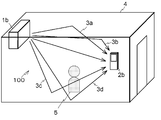
- FIG. 6 shows the configuration of the located area detection system 100 according to the second embodiment.
- the transmitter 1b is a parent device of a sensor device that performs wireless communication with a remote controller or a controller, or a home appliance that is operated with the remote controller.
- Other configurations are the same as those of the first embodiment.
- the receiver 2 b includes an antenna 6, a radio circuit 7 b, a reception level measurement circuit 8, a located area determination unit 9, a control unit 10, a storage unit 11, and a modem unit 17.
- the radio circuit 7 is connected to the reception level measurement circuit 8 and the modem 17.
- the modem 17 has a function of modulating / demodulating communication signals.
- the radio circuit 7b includes a reception circuit and a transmission circuit composed of PA (Power Amp.) And the like. Other configurations are the same as those of the first embodiment.
- the transmitter 1b When the transmitter 1b starts operating, it waits for access from the receiver 2b.
- the location determination unit 9 transmits a request for acquiring the location detection intervals T1 and T2 and the next location detection signal transmission time to the transmitter 1b.
- the transmitted request is modulated by the modem unit 17 and wirelessly transmitted via the wireless circuit 7 b and the antenna 6.
- the request transmitted wirelessly is received by the transmitter 1b.
- the transmitter 1b transmits the in-zone detection interval T1 and the next in-zone detection signal transmission time to the receiver 2b.
- the data transmitted from the transmitter 1b is input to the location detection unit 9 via the antenna 6, the radio circuit 7b, and the modem unit 17 of the receiver 2b.
- the in-zone detection unit 9 writes the in-zone detection interval T1 in the storage unit 11, and shifts the receiver 2b to the sleep state by the timer control until the next in-zone detection signal transmission time.
- the receiver 2b shifts to the reception standby state and receives the located area detection signal transmitted from the transmitter 1b.
- the transmitter 1b and the receiver 2b need to have accurate clocks.
- a ceramic oscillator mainly used as a clock for consumer equipment has a clock accuracy of about 0.1%. This is an error of 60 msec at a time interval of 1 minute. Therefore, it is necessary to lengthen the reception waiting time of the presence detection signal on the receiver 2b side in accordance with the clock error. Further, error accumulation can be reduced by correcting the clock error according to the reception timing of the in-zone detection signal.
- the in-zone detection signal received by the antenna 6 is input to the reception level measurement circuit 8 via the radio circuit 7a.
- the reception level of the located area detection signal transmitted by the transmitter 1 b is measured and input to the located area determination unit 9. At this time, a process of receiving and averaging the in-zone detection signal a plurality of times may be performed.
- the reception level input to the location determination unit 9 is compared with the upper limit value and the lower limit value of the fluctuation range of the reception level when no person is present.
- the upper limit value and the lower limit value of the fluctuation range of the reception level are set and adjusted in advance in the receiver 2b as in the first embodiment.
- the location determination unit 9 of the receiver 2b When the previous location detection result in the receiver 2b is absent, when the reception level is higher than the upper limit value or lower than the lower limit value, the location determination unit 9 of the receiver 2b Then, a continuous transmission request for the presence detection signal is transmitted.
- the location determination unit 9 of the receiver 2b sends the transmitter 1b On the other hand, a continuous transmission request for the presence detection signal is transmitted.
- the transmitter 1b that has received the continuous transmission request for the location detection signal continuously transmits the location detection signal. Other operations are the same as those in the first embodiment.
- a radio signal is received only when a multipath radio signal is received at a long-range in-zone detection interval T1 and a change in the reception level is detected.
- the interval detection signal is shortened to T2 to continuously receive the in-zone detection signal. This eliminates the need to constantly receive a radio signal, so that it is possible to easily and widely detect the person's location while reducing power consumption.
- the in-zone detection signal is transmitted with low frequency, and only when there is a request from the receiver 2b, the in-zone detection signal is transmitted with an increased frequency.
- the power consumption of the machine 1b can be reduced.
- the home appliance can be controlled based on the location detection information using the location detection system, the convenience for the user is increased.
- the reception level measurement result is equal to or lower than the upper limit value L1 and lower limit value L2 of the fluctuation range of the reception level when no person is present, or is greater than the upper limit value L1 or smaller than the lower limit value L2.
- This determination is made by receiving the in-zone detection signal once, but it may be determined by the result of receiving the in-zone detection signal a plurality of times. In this case, for example, the determination may be made by majority decision of a plurality of received results, or may be determined using an average value. In this way, the determination reliability can be further improved.
- the upper limit value L1 and the lower limit value L2 of the fluctuation range of the reception level when no person is present are the absolute values of the reception level. You may make it make a deviation into a threshold value. In this way, the determination reliability can be further improved.
- the program to be executed is a computer-readable recording medium such as a flexible disk, a CD-ROM (Compact Disc-Read-Only Memory), a DVD (Digital Versatile Disc), and an MO (Magneto-Optical Disc).
- a system that executes the above-described thread may be configured by storing and distributing the program in a medium and installing the program.
- the program may be stored in a disk device or the like of a predetermined server device on a communication network such as the Internet, and may be downloaded, for example, superimposed on a carrier wave.
- This invention is suitable for detecting whether or not there is a person in a predetermined space.
Abstract
Description
まず、この発明の実施の形態1について説明する。
First, a first embodiment of the present invention will be described.
次に、この発明の実施の形態2について説明する。 Embodiment 2. FIG.
Next, a second embodiment of the present invention will be described.
2a、2b 受信機
3a、3b、3c、3d 伝搬経路
4 在圏検知エリア
5 人
6 アンテナ
7a、7b 無線回路
8 受信レベル測定回路
9 在圏判定部
10 制御部
11 記憶部
17 モデム部
100 在圏検知システム 1a,
Claims (11)
- 所定の空間内において、マルチパスの無線信号を送信する送信機と、送信された無線信号を受信して人物の在圏を検知する受信機とを備え、
前記受信機は、
第1の間隔で間欠的に受信される前記無線信号の受信レベルに基づいて、人物の在圏/不在の状態に変化があったか否かを判定する第1の判定部と、
前記第1の判定部で前記無線信号の受信レベルが変化したと判定された場合に、前記第1の間隔よりも短い第2の間隔で受信される前記無線信号の受信レベルのばらつきに基づいて、人物の在圏/不在を判定する第2の判定部と、
を備える在圏検知システム。 In a predetermined space, a transmitter that transmits a multipath radio signal, and a receiver that receives the transmitted radio signal and detects a person's location,
The receiver
A first determination unit that determines whether or not there is a change in the presence / absence state of the person based on the reception level of the wireless signal received intermittently at a first interval;
When it is determined by the first determination unit that the reception level of the wireless signal has changed, based on a variation in the reception level of the wireless signal received at a second interval shorter than the first interval A second determination unit for determining presence / absence of a person;
In-zone detection system equipped with. - 前記送信機は、
所定の空間内に設置され一定の送信電力で前記無線信号を送信する所定の無線通信サービスに用いられる送信機である、
請求項1に記載の在圏検知システム。 The transmitter is
A transmitter used in a predetermined wireless communication service installed in a predetermined space and transmitting the wireless signal with a constant transmission power;
The location detection system according to claim 1. - 前記送信機は、
前記第1の間隔及び前記第2の間隔のいずれかで前記無線信号を送信可能であり、
前記受信機からの要求により、送信間隔を前記第1の間隔から前記第2の間隔に切り替え、
前記受信機は、
前記第1の判定部で、人物の在圏/不在の状態に変化があったと判定された場合に、前記送信機に、送信頻度を上げる要求を送信する、
請求項1又は2に記載の在圏検知システム。 The transmitter is
The wireless signal can be transmitted at either the first interval or the second interval;
In response to a request from the receiver, the transmission interval is switched from the first interval to the second interval,
The receiver
When the first determination unit determines that there is a change in the presence / absence state of the person, a request to increase the transmission frequency is transmitted to the transmitter.
The in-zone detection system according to claim 1 or 2. - 前記第1の判定部は、
前記無線信号の受信レベルに関するデータが、人物不在時の受信レベルの変動範囲内に収まっているか否かにより、人物の在圏/不在の状態に変化があったと判定する、
請求項1乃至3のいずれか一項に記載の在圏検知システム。 The first determination unit includes:
It is determined that there has been a change in the presence / absence state of the person depending on whether or not the data regarding the reception level of the wireless signal is within the fluctuation range of the reception level when the person is absent.
The in-zone detection system according to any one of claims 1 to 3. - 過去に測定された前記無線信号の受信レベルに基づいて、人物不在時の受信レベルの変動範囲を調整する調整部をさらに備える、
請求項4に記載の在圏検知システム。 Based on the reception level of the wireless signal measured in the past, further comprising an adjustment unit that adjusts the fluctuation range of the reception level when the person is absent.
The in-zone detection system according to claim 4. - 前記第1の判定部は、
複数回受信された前記無線信号の受信レベルの平均値が、人物不在時の受信レベルの変動範囲内に収まっているか否かにより、人物の在圏/不在の状態に変化があったと判定する、
請求項4又は5に記載の在圏検知システム。 The first determination unit includes:
It is determined that there is a change in the presence / absence state of the person depending on whether the average value of the reception level of the wireless signal received a plurality of times is within the fluctuation range of the reception level when the person is absent,
The in-zone detection system according to claim 4 or 5. - 前記第1の判定部は、
複数回受信された前記無線信号の受信レベルのうち、人物不在時の受信レベルの変動範囲内に収まっていないものの数が半数を上回るか否かにより、人物の在圏/不在の状態に変化があったと判定する、
請求項4又は5に記載の在圏検知システム。 The first determination unit includes:
The presence / absence state of the person changes depending on whether or not the number of reception levels of the radio signal received a plurality of times does not fall within the fluctuation range of the reception level when the person is absent exceeds half. Judge that there was
The in-zone detection system according to claim 4 or 5. - 前記第2の判定部は、
複数回受信された前記無線信号の受信レベルの標準偏差が、閾値を超える場合に、人物の在圏/不在を判定する、
請求項4に記載の在圏検知システム。 The second determination unit includes:
Determining the presence / absence of a person when the standard deviation of the reception level of the radio signal received a plurality of times exceeds a threshold;
The located area detection system according to claim 4. - 前記閾値を、
過去に測定された前記無線信号の受信レベルに基づいて調整する調整部をさらに備える、
請求項8に記載の在圏検知システム。 The threshold is
An adjustment unit configured to adjust based on a reception level of the wireless signal measured in the past;
The located area detection system according to claim 8. - 所定の空間内において、マルチパスの無線信号を送信する送信機と、送信された無線信号を受信して人物の在圏を検知する受信機とを備えるシステムを用いた在圏検知方法であって、
前記受信機により、第1の間隔で間欠的に受信される前記無線信号の受信レベルに基づいて、人物の在圏/不在の状態に変化があったか否かを判定する第1の判定工程と、
前記第1の判定工程において前記無線信号の受信レベルが変化したと判定された場合に、前記受信機により、前記第1の間隔よりも短い第2の間隔で受信される前記無線信号の受信レベルのばらつきに基づいて、人物の在圏/不在を判定する第2の判定工程と、
を含む在圏検知方法。 A location detection method using a system including a transmitter that transmits a multipath wireless signal and a receiver that receives a transmitted wireless signal and detects a person's location within a predetermined space. ,
A first determination step of determining whether or not the presence / absence state of the person has changed based on a reception level of the wireless signal intermittently received at a first interval by the receiver;
The reception level of the radio signal received by the receiver at a second interval shorter than the first interval when the reception level of the radio signal is determined to have changed in the first determination step. A second determination step of determining the presence / absence of a person based on the variation of
Location detection method including - 所定の空間内において、送信機から送信されるマルチパスの無線信号を受信して人物の在圏を検知する受信機を制御するコンピュータを、
前記受信機により、第1の間隔で間欠的に受信される前記無線信号の受信レベルに基づいて、人物の在圏/不在の状態に変化があったか否かを判定する第1の判定部、
前記第1の判定部で前記無線信号の受信レベルが変化したと判定された場合に、前記受信機により、前記第1の間隔よりも短い第2の間隔で受信される前記無線信号の受信レベルのばらつきに基づいて、人物の在圏/不在を判定する第2の判定部、
として機能させるプログラム。 In a predetermined space, a computer that controls a receiver that receives a multipath radio signal transmitted from a transmitter and detects a person's location,
A first determination unit configured to determine whether or not the presence / absence state of the person has changed based on a reception level of the wireless signal that is intermittently received by the receiver at a first interval;
The reception level of the radio signal received by the receiver at a second interval shorter than the first interval when the first determination unit determines that the reception level of the radio signal has changed. A second determination unit for determining the presence / absence of a person based on the variation of
Program to function as.
Priority Applications (5)
| Application Number | Priority Date | Filing Date | Title |
|---|---|---|---|
| EP11863171.2A EP2696332B1 (en) | 2011-04-04 | 2011-04-04 | Presence detection system, presence detection method, and program |
| PCT/JP2011/058528 WO2012137285A1 (en) | 2011-04-04 | 2011-04-04 | Presence detection system, presence detection method, and program |
| US14/009,343 US9383438B2 (en) | 2011-04-04 | 2011-04-04 | Presence detection system, presence detection method, and program |
| CN201180069819.8A CN103460263B (en) | 2011-04-04 | 2011-04-04 | In room detection system, at room detection method |
| JP2013508647A JPWO2012137285A1 (en) | 2011-04-04 | 2011-04-04 | Area detection system, area detection method and program |
Applications Claiming Priority (1)
| Application Number | Priority Date | Filing Date | Title |
|---|---|---|---|
| PCT/JP2011/058528 WO2012137285A1 (en) | 2011-04-04 | 2011-04-04 | Presence detection system, presence detection method, and program |
Publications (1)
| Publication Number | Publication Date |
|---|---|
| WO2012137285A1 true WO2012137285A1 (en) | 2012-10-11 |
Family
ID=46968726
Family Applications (1)
| Application Number | Title | Priority Date | Filing Date |
|---|---|---|---|
| PCT/JP2011/058528 WO2012137285A1 (en) | 2011-04-04 | 2011-04-04 | Presence detection system, presence detection method, and program |
Country Status (5)
| Country | Link |
|---|---|
| US (1) | US9383438B2 (en) |
| EP (1) | EP2696332B1 (en) |
| JP (1) | JPWO2012137285A1 (en) |
| CN (1) | CN103460263B (en) |
| WO (1) | WO2012137285A1 (en) |
Cited By (12)
| Publication number | Priority date | Publication date | Assignee | Title |
|---|---|---|---|---|
| WO2015025527A1 (en) * | 2013-08-23 | 2015-02-26 | パナソニックIpマネジメント株式会社 | Object detection device for vehicle |
| JP2015144796A (en) * | 2014-02-03 | 2015-08-13 | 株式会社ギガテック | Human body detection by microwave doppler sensor and biological monitoring method |
| WO2016103394A1 (en) * | 2014-12-25 | 2016-06-30 | 三菱電機株式会社 | State detection system, air-conditioning control system and state detection method |
| WO2016157779A1 (en) * | 2015-03-27 | 2016-10-06 | 株式会社デンソー | Object detection apparatus |
| WO2017013760A1 (en) * | 2015-07-22 | 2017-01-26 | 三菱電機株式会社 | Wireless communication device, presence detection system, method, and program |
| JP2019507999A (en) * | 2016-02-04 | 2019-03-22 | エアリアル テクノロジーズ インコーポレイテッド | System and method for detecting the environment of wireless communication signals |
| JP2019510960A (en) * | 2016-01-05 | 2019-04-18 | ロシックス・インコーポレイテッド | System and method for monitoring an environment using radio frequency signals and sensors |
| JP2019090548A (en) * | 2017-11-13 | 2019-06-13 | 三菱電機株式会社 | Air conditioning control system, remote control device and air conditioning control method |
| JP2020511654A (en) * | 2017-03-16 | 2020-04-16 | コグニティヴ システムズ コーポレイション | Storage of modem parameters for motion detection |
| JP2021501308A (en) * | 2017-10-31 | 2021-01-14 | コグニティヴ システムズ コーポレイション | Motion detection based on grouping of statistical parameters of wireless signals |
| JP2022028703A (en) * | 2016-04-14 | 2022-02-16 | オリジン ワイヤレス, インコーポレイテッド | Object tracking method, device, server and system |
| WO2023286489A1 (en) * | 2021-07-16 | 2023-01-19 | ソニーセミコンダクタソリューションズ株式会社 | Communication processing device, communication system, and communication processing method |
Families Citing this family (41)
| Publication number | Priority date | Publication date | Assignee | Title |
|---|---|---|---|---|
| US10361585B2 (en) | 2014-01-27 | 2019-07-23 | Ivani, LLC | Systems and methods to allow for a smart device |
| DE102014208386A1 (en) * | 2014-05-06 | 2015-11-12 | Robert Bosch Gmbh | Method and device for monitoring an immobile spatial area |
| FR3031194B1 (en) * | 2014-12-29 | 2018-04-06 | Centre National De La Recherche Scientifique | METHOD AND DEVICE FOR DETECTING AND LOCATING INDIVIDUALS OR OBJECTS |
| US10028220B2 (en) | 2015-01-27 | 2018-07-17 | Locix, Inc. | Systems and methods for providing wireless asymmetric network architectures of wireless devices with power management features |
| KR102314833B1 (en) * | 2015-03-26 | 2021-10-19 | 한국전자통신연구원 | Apparatus and Method for Recognizing Object using Spatial Electronic Wave |
| US9474042B1 (en) | 2015-09-16 | 2016-10-18 | Ivani, LLC | Detecting location within a network |
| US10321270B2 (en) | 2015-09-16 | 2019-06-11 | Ivani, LLC | Reverse-beacon indoor positioning system using existing detection fields |
| US10665284B2 (en) | 2015-09-16 | 2020-05-26 | Ivani, LLC | Detecting location within a network |
| US10455357B2 (en) | 2015-09-16 | 2019-10-22 | Ivani, LLC | Detecting location within a network |
| US11350238B2 (en) | 2015-09-16 | 2022-05-31 | Ivani, LLC | Systems and methods for detecting the presence of a user at a computer |
| US11533584B2 (en) | 2015-09-16 | 2022-12-20 | Ivani, LLC | Blockchain systems and methods for confirming presence |
| US10382893B1 (en) | 2015-09-16 | 2019-08-13 | Ivani, LLC | Building system control utilizing building occupancy |
| US11030902B2 (en) | 2016-01-05 | 2021-06-08 | Locix, Inc. | Systems and methods for using radio frequency signals and sensors to monitor environments |
| US10504364B2 (en) | 2016-01-05 | 2019-12-10 | Locix, Inc. | Systems and methods for using radio frequency signals and sensors to monitor environments |
| US9523760B1 (en) | 2016-04-15 | 2016-12-20 | Cognitive Systems Corp. | Detecting motion based on repeated wireless transmissions |
| US9584974B1 (en) | 2016-05-11 | 2017-02-28 | Cognitive Systems Corp. | Detecting motion based on reference signal transmissions |
| US10129853B2 (en) | 2016-06-08 | 2018-11-13 | Cognitive Systems Corp. | Operating a motion detection channel in a wireless communication network |
| US10455350B2 (en) | 2016-07-10 | 2019-10-22 | ZaiNar, Inc. | Method and system for radiolocation asset tracking via a mesh network |
| US9524628B1 (en) | 2016-08-04 | 2016-12-20 | Cognitive Systems Corp. | Detecting signal modulation for motion detection |
| US9927519B1 (en) | 2017-03-16 | 2018-03-27 | Cognitive Systems Corp. | Categorizing motion detected using wireless signals |
| US10111228B2 (en) | 2017-03-16 | 2018-10-23 | Cognitive Systems Corp. | Selecting wireless communication channels based on signal quality metrics |
| US9989622B1 (en) | 2017-03-16 | 2018-06-05 | Cognitive Systems Corp. | Controlling radio states for motion detection |
| US10380870B2 (en) * | 2017-05-05 | 2019-08-13 | Hubbell Incorporated | Device and method for controlling Bluetooth™ enabled occupancy sensors |
| DE102017109935A1 (en) | 2017-05-09 | 2018-11-15 | Miele & Cie. Kg | Method for operating a household appliance |
| US10056129B1 (en) | 2017-08-10 | 2018-08-21 | Micron Technology, Inc. | Cell bottom node reset in a memory array |
| US10051414B1 (en) | 2017-08-30 | 2018-08-14 | Cognitive Systems Corp. | Detecting motion based on decompositions of channel response variations |
| US10109167B1 (en) | 2017-10-20 | 2018-10-23 | Cognitive Systems Corp. | Motion localization in a wireless mesh network based on motion indicator values |
| US10228439B1 (en) | 2017-10-31 | 2019-03-12 | Cognitive Systems Corp. | Motion detection based on filtered statistical parameters of wireless signals |
| US9933517B1 (en) * | 2017-11-03 | 2018-04-03 | Cognitive Systems Corp. | Time-alignment of motion detection signals using buffers |
| US10109168B1 (en) | 2017-11-16 | 2018-10-23 | Cognitive Systems Corp. | Motion localization based on channel response characteristics |
| US10108903B1 (en) * | 2017-12-08 | 2018-10-23 | Cognitive Systems Corp. | Motion detection based on machine learning of wireless signal properties |
| US11057862B2 (en) | 2018-08-26 | 2021-07-06 | Celeno Communications (Israel) Ltd. | Wi-Fi radar detection using synchronized wireless access point |
| WO2020141417A1 (en) | 2018-12-31 | 2020-07-09 | Celeno Communications (Israel) Ltd. | Coherent wi-fi radar using wireless access point |
| US11102750B2 (en) | 2019-01-01 | 2021-08-24 | Celeno Communications (Israel) Ltd. | Positioning system based on distributed transmission and reception of Wi-Fi signals |
| BE1027136B1 (en) * | 2019-03-21 | 2020-10-19 | Rombit Nv | Method, system and computer program product for determining a position relative to a bounded space |
| RU2726012C1 (en) * | 2019-07-01 | 2020-07-08 | Российская Федерация, от имени которой выступает Государственная корпорация по атомной энергии "Росатом" (Госкорпорация "Росатом") | Radio-beam device with volumetric detection zone for perimeters and rooms |
| US11570712B2 (en) | 2019-10-31 | 2023-01-31 | Cognitive Systems Corp. | Varying a rate of eliciting MIMO transmissions from wireless communication devices |
| CN114599991A (en) | 2019-10-31 | 2022-06-07 | 认知系统公司 | Causing MIMO transmissions from a wireless communication device |
| US11385344B2 (en) * | 2020-03-20 | 2022-07-12 | Aptiv Technologies Limited | Frequency-modulated continuous-wave (FMCW) radar-based detection of living objects |
| US11070399B1 (en) | 2020-11-30 | 2021-07-20 | Cognitive Systems Corp. | Filtering channel responses for motion detection |
| WO2022149621A1 (en) * | 2021-01-05 | 2022-07-14 | 엘지전자 주식회사 | Method and apparatus for performing wireless sensing by collecting empty data on basis of wireless sensing |
Citations (4)
| Publication number | Priority date | Publication date | Assignee | Title |
|---|---|---|---|---|
| JPH0879840A (en) * | 1994-08-31 | 1996-03-22 | Sharp Corp | Home control system |
| JPH1020925A (en) * | 1996-07-05 | 1998-01-23 | Toshiba Corp | Plant diagnostic device |
| JP2003230174A (en) * | 2003-02-14 | 2003-08-15 | Nippon Telegr & Teleph Corp <Ntt> | Method for position detection |
| JP2006221213A (en) | 2005-02-08 | 2006-08-24 | Masahiro Nishi | Figure existence detection system |
Family Cites Families (22)
| Publication number | Priority date | Publication date | Assignee | Title |
|---|---|---|---|---|
| JPS50142057A (en) * | 1974-05-01 | 1975-11-15 | ||
| JPS63181587A (en) * | 1987-01-23 | 1988-07-26 | Toshiba Corp | Invasion monitoring device |
| JP3001730B2 (en) * | 1992-09-22 | 2000-01-24 | 九州電力株式会社 | Moving object detection method and apparatus |
| JP3469956B2 (en) * | 1995-03-27 | 2003-11-25 | マスプロ電工株式会社 | Shoplifter |
| JP3337872B2 (en) * | 1995-06-13 | 2002-10-28 | セイコープレシジョン株式会社 | Object detection device |
| FR2745093B1 (en) * | 1996-02-21 | 1998-04-24 | Legrand Sa | METHOD AND DEVICE FOR DETECTING THE PRESENCE OF A LIVING BEING OF A PARTICULAR SPECIES IN A SPACE MONITORED BY A DOPPLER SENSOR |
| US5969595A (en) * | 1996-07-22 | 1999-10-19 | Trimble Navigation Limited | Security for transport vehicles and cargo |
| US6239736B1 (en) * | 1999-04-21 | 2001-05-29 | Interlogix, Inc. | Range-gated radar motion detector |
| JP4513154B2 (en) * | 2000-02-14 | 2010-07-28 | ソニー株式会社 | Reception circuit and security system using the same |
| US6281797B1 (en) * | 2000-04-04 | 2001-08-28 | Marconi Data Systems Inc. | Method and apparatus for detecting a container proximate to a transportation vessel hold |
| US6437702B1 (en) * | 2000-04-14 | 2002-08-20 | Qualcomm, Inc. | Cargo sensing system and method |
| EP1239421B1 (en) * | 2001-03-08 | 2008-10-15 | EM Microelectronic-Marin SA | Passage detection system for individuals or objects through an entrance-exit with a limited space |
| US20030210139A1 (en) * | 2001-12-03 | 2003-11-13 | Stephen Brooks | Method and system for improved security |
| US7088236B2 (en) * | 2002-06-26 | 2006-08-08 | It University Of Copenhagen | Method of and a system for surveillance of an environment utilising electromagnetic waves |
| US20050055568A1 (en) * | 2003-08-12 | 2005-03-10 | Agrawala Ashok K. | Method and system for providing physical security in an area of interest |
| US7019683B2 (en) * | 2004-03-05 | 2006-03-28 | General Electric Company | Shipping container security system |
| JP4301080B2 (en) * | 2004-05-24 | 2009-07-22 | 船井電機株式会社 | Monitoring system |
| CN100440264C (en) * | 2005-11-30 | 2008-12-03 | 中国科学院声学研究所 | Supersonic invasion detection method and detection device |
| US7884727B2 (en) * | 2007-05-24 | 2011-02-08 | Bao Tran | Wireless occupancy and day-light sensing |
| US8525725B2 (en) * | 2010-03-09 | 2013-09-03 | Lockheed Martin Corporation | Method and system for position and track determination |
| JP2011215031A (en) * | 2010-03-31 | 2011-10-27 | Toshiba Corp | Human detection sensor and air conditioner |
| US8816895B2 (en) * | 2011-04-15 | 2014-08-26 | Raytheon Company | Target-tracking radar classifier with glint detection and method for target classification using measured target epsilon and target glint information |
-
2011
- 2011-04-04 EP EP11863171.2A patent/EP2696332B1/en active Active
- 2011-04-04 WO PCT/JP2011/058528 patent/WO2012137285A1/en active Application Filing
- 2011-04-04 CN CN201180069819.8A patent/CN103460263B/en active Active
- 2011-04-04 US US14/009,343 patent/US9383438B2/en active Active
- 2011-04-04 JP JP2013508647A patent/JPWO2012137285A1/en active Pending
Patent Citations (4)
| Publication number | Priority date | Publication date | Assignee | Title |
|---|---|---|---|---|
| JPH0879840A (en) * | 1994-08-31 | 1996-03-22 | Sharp Corp | Home control system |
| JPH1020925A (en) * | 1996-07-05 | 1998-01-23 | Toshiba Corp | Plant diagnostic device |
| JP2003230174A (en) * | 2003-02-14 | 2003-08-15 | Nippon Telegr & Teleph Corp <Ntt> | Method for position detection |
| JP2006221213A (en) | 2005-02-08 | 2006-08-24 | Masahiro Nishi | Figure existence detection system |
Cited By (21)
| Publication number | Priority date | Publication date | Assignee | Title |
|---|---|---|---|---|
| JP2015040837A (en) * | 2013-08-23 | 2015-03-02 | パナソニックIpマネジメント株式会社 | Vehicular article detection device |
| CN105474038A (en) * | 2013-08-23 | 2016-04-06 | 松下知识产权经营株式会社 | Object detection device for vehicle |
| WO2015025527A1 (en) * | 2013-08-23 | 2015-02-26 | パナソニックIpマネジメント株式会社 | Object detection device for vehicle |
| JP2015144796A (en) * | 2014-02-03 | 2015-08-13 | 株式会社ギガテック | Human body detection by microwave doppler sensor and biological monitoring method |
| WO2016103394A1 (en) * | 2014-12-25 | 2016-06-30 | 三菱電機株式会社 | State detection system, air-conditioning control system and state detection method |
| JPWO2016103394A1 (en) * | 2014-12-25 | 2017-06-15 | 三菱電機株式会社 | State detection system, air conditioning control system, and state detection method |
| US10677904B2 (en) | 2015-03-27 | 2020-06-09 | Denso Corporation | Object detection apparatus |
| WO2016157779A1 (en) * | 2015-03-27 | 2016-10-06 | 株式会社デンソー | Object detection apparatus |
| JP2016186456A (en) * | 2015-03-27 | 2016-10-27 | 株式会社日本自動車部品総合研究所 | Object detection device |
| WO2017013760A1 (en) * | 2015-07-22 | 2017-01-26 | 三菱電機株式会社 | Wireless communication device, presence detection system, method, and program |
| JPWO2017013760A1 (en) * | 2015-07-22 | 2017-11-02 | 三菱電機株式会社 | Wireless communication apparatus, presence detection system, method, and program |
| JP2019510960A (en) * | 2016-01-05 | 2019-04-18 | ロシックス・インコーポレイテッド | System and method for monitoring an environment using radio frequency signals and sensors |
| JP2019507999A (en) * | 2016-02-04 | 2019-03-22 | エアリアル テクノロジーズ インコーポレイテッド | System and method for detecting the environment of wireless communication signals |
| JP2022028703A (en) * | 2016-04-14 | 2022-02-16 | オリジン ワイヤレス, インコーポレイテッド | Object tracking method, device, server and system |
| JP7365593B2 (en) | 2016-04-14 | 2023-10-20 | オリジン ワイヤレス, インコーポレイテッド | Methods, devices, servers and systems for object tracking |
| JP2020511654A (en) * | 2017-03-16 | 2020-04-16 | コグニティヴ システムズ コーポレイション | Storage of modem parameters for motion detection |
| JP7003146B2 (en) | 2017-03-16 | 2022-01-20 | コグニティヴ システムズ コーポレイション | Memory of modem parameters for motion detection |
| JP2021501308A (en) * | 2017-10-31 | 2021-01-14 | コグニティヴ システムズ コーポレイション | Motion detection based on grouping of statistical parameters of wireless signals |
| JP7249337B2 (en) | 2017-10-31 | 2023-03-30 | コグニティヴ システムズ コーポレイション | Motion Detection Based on Grouping of Statistical Parameters of Wireless Signals |
| JP2019090548A (en) * | 2017-11-13 | 2019-06-13 | 三菱電機株式会社 | Air conditioning control system, remote control device and air conditioning control method |
| WO2023286489A1 (en) * | 2021-07-16 | 2023-01-19 | ソニーセミコンダクタソリューションズ株式会社 | Communication processing device, communication system, and communication processing method |
Also Published As
| Publication number | Publication date |
|---|---|
| EP2696332A4 (en) | 2014-09-17 |
| EP2696332A1 (en) | 2014-02-12 |
| JPWO2012137285A1 (en) | 2014-07-28 |
| CN103460263B (en) | 2015-12-09 |
| EP2696332B1 (en) | 2020-05-06 |
| US20140015706A1 (en) | 2014-01-16 |
| US9383438B2 (en) | 2016-07-05 |
| CN103460263A (en) | 2013-12-18 |
Similar Documents
| Publication | Publication Date | Title |
|---|---|---|
| WO2012137285A1 (en) | Presence detection system, presence detection method, and program | |
| KR101738760B1 (en) | Method and system for optimized bluetooth low energy communications | |
| US10514704B2 (en) | Systems and methods for using radio frequency signals and sensors to monitor environments | |
| KR100850445B1 (en) | Wireless system with transmission power control | |
| US9952569B2 (en) | Association of a portable sensor device in a building management system | |
| WO2018216088A1 (en) | Human position detection device, human position detection system, human position detection method, and program | |
| US20150002271A1 (en) | Variable listen duration and/or synchronized wake-up of asset tags | |
| US8552838B2 (en) | Passive wireless system | |
| US11297592B2 (en) | Electronic beacon for a localization system | |
| JP4572305B2 (en) | Person presence detection system | |
| JP6355761B2 (en) | State detection system, air conditioning control system, and state detection method | |
| JP6925241B2 (en) | Air conditioning control system, remote control device and air conditioning control method | |
| JP6342077B2 (en) | Wireless communication apparatus, presence detection system, method, and program | |
| CN103363625A (en) | Intelligent remote control with Doppler microwave sensor | |
| EP2511785B1 (en) | Devices, methods, and systems for occupancy detection | |
| KR20110020677A (en) | Wireless parking detector using multiple antennas and its detecting methods | |
| JPWO2020012743A1 (en) | Receiver and control method of receiver | |
| US20230232252A1 (en) | Configuration module for configuring a network device of a radiofrequency sensing network | |
| WO2023280783A1 (en) | Configuring radiofrequency sensing nodes |
Legal Events
| Date | Code | Title | Description |
|---|---|---|---|
| 121 | Ep: the epo has been informed by wipo that ep was designated in this application |
Ref document number: 11863171 Country of ref document: EP Kind code of ref document: A1 |
|
| ENP | Entry into the national phase |
Ref document number: 2013508647 Country of ref document: JP Kind code of ref document: A |
|
| WWE | Wipo information: entry into national phase |
Ref document number: 14009343 Country of ref document: US |
|
| NENP | Non-entry into the national phase |
Ref country code: DE |
|
| WWE | Wipo information: entry into national phase |
Ref document number: 2011863171 Country of ref document: EP |