WO2012137257A1 - Railway bogie - Google Patents
Railway bogie Download PDFInfo
- Publication number
- WO2012137257A1 WO2012137257A1 PCT/JP2011/002072 JP2011002072W WO2012137257A1 WO 2012137257 A1 WO2012137257 A1 WO 2012137257A1 JP 2011002072 W JP2011002072 W JP 2011002072W WO 2012137257 A1 WO2012137257 A1 WO 2012137257A1
- Authority
- WO
- WIPO (PCT)
- Prior art keywords
- leaf spring
- spring
- bogie
- supported
- rear direction
- Prior art date
Links
Images


Classifications
-
- B—PERFORMING OPERATIONS; TRANSPORTING
- B61—RAILWAYS
- B61F—RAIL VEHICLE SUSPENSIONS, e.g. UNDERFRAMES, BOGIES OR ARRANGEMENTS OF WHEEL AXLES; RAIL VEHICLES FOR USE ON TRACKS OF DIFFERENT WIDTH; PREVENTING DERAILING OF RAIL VEHICLES; WHEEL GUARDS, OBSTRUCTION REMOVERS OR THE LIKE FOR RAIL VEHICLES
- B61F5/00—Constructional details of bogies; Connections between bogies and vehicle underframes; Arrangements or devices for adjusting or allowing self-adjustment of wheel axles or bogies when rounding curves
- B61F5/26—Mounting or securing axle-boxes in vehicle or bogie underframes
- B61F5/30—Axle-boxes mounted for movement under spring control in vehicle or bogie underframes
-
- B—PERFORMING OPERATIONS; TRANSPORTING
- B61—RAILWAYS
- B61F—RAIL VEHICLE SUSPENSIONS, e.g. UNDERFRAMES, BOGIES OR ARRANGEMENTS OF WHEEL AXLES; RAIL VEHICLES FOR USE ON TRACKS OF DIFFERENT WIDTH; PREVENTING DERAILING OF RAIL VEHICLES; WHEEL GUARDS, OBSTRUCTION REMOVERS OR THE LIKE FOR RAIL VEHICLES
- B61F3/00—Types of bogies
- B61F3/02—Types of bogies with more than one axle
- B61F3/04—Types of bogies with more than one axle with driven axles or wheels
-
- B—PERFORMING OPERATIONS; TRANSPORTING
- B61—RAILWAYS
- B61C—LOCOMOTIVES; MOTOR RAILCARS
- B61C9/00—Locomotives or motor railcars characterised by the type of transmission system used; Transmission systems specially adapted for locomotives or motor railcars
- B61C9/38—Transmission systems in or for locomotives or motor railcars with electric motor propulsion
- B61C9/48—Transmission systems in or for locomotives or motor railcars with electric motor propulsion with motors supported on vehicle frames and driving axles, e.g. axle or nose suspension
- B61C9/50—Transmission systems in or for locomotives or motor railcars with electric motor propulsion with motors supported on vehicle frames and driving axles, e.g. axle or nose suspension in bogies
-
- B—PERFORMING OPERATIONS; TRANSPORTING
- B61—RAILWAYS
- B61F—RAIL VEHICLE SUSPENSIONS, e.g. UNDERFRAMES, BOGIES OR ARRANGEMENTS OF WHEEL AXLES; RAIL VEHICLES FOR USE ON TRACKS OF DIFFERENT WIDTH; PREVENTING DERAILING OF RAIL VEHICLES; WHEEL GUARDS, OBSTRUCTION REMOVERS OR THE LIKE FOR RAIL VEHICLES
- B61F5/00—Constructional details of bogies; Connections between bogies and vehicle underframes; Arrangements or devices for adjusting or allowing self-adjustment of wheel axles or bogies when rounding curves
- B61F5/26—Mounting or securing axle-boxes in vehicle or bogie underframes
- B61F5/30—Axle-boxes mounted for movement under spring control in vehicle or bogie underframes
- B61F5/301—Axle-boxes mounted for movement under spring control in vehicle or bogie underframes incorporating metal springs
- B61F5/302—Leaf springs
-
- B—PERFORMING OPERATIONS; TRANSPORTING
- B61—RAILWAYS
- B61F—RAIL VEHICLE SUSPENSIONS, e.g. UNDERFRAMES, BOGIES OR ARRANGEMENTS OF WHEEL AXLES; RAIL VEHICLES FOR USE ON TRACKS OF DIFFERENT WIDTH; PREVENTING DERAILING OF RAIL VEHICLES; WHEEL GUARDS, OBSTRUCTION REMOVERS OR THE LIKE FOR RAIL VEHICLES
- B61F5/00—Constructional details of bogies; Connections between bogies and vehicle underframes; Arrangements or devices for adjusting or allowing self-adjustment of wheel axles or bogies when rounding curves
- B61F5/38—Arrangements or devices for adjusting or allowing self- adjustment of wheel axles or bogies when rounding curves, e.g. sliding axles, swinging axles
-
- B—PERFORMING OPERATIONS; TRANSPORTING
- B61—RAILWAYS
- B61F—RAIL VEHICLE SUSPENSIONS, e.g. UNDERFRAMES, BOGIES OR ARRANGEMENTS OF WHEEL AXLES; RAIL VEHICLES FOR USE ON TRACKS OF DIFFERENT WIDTH; PREVENTING DERAILING OF RAIL VEHICLES; WHEEL GUARDS, OBSTRUCTION REMOVERS OR THE LIKE FOR RAIL VEHICLES
- B61F5/00—Constructional details of bogies; Connections between bogies and vehicle underframes; Arrangements or devices for adjusting or allowing self-adjustment of wheel axles or bogies when rounding curves
- B61F5/50—Other details
- B61F5/52—Bogie frames
Definitions
- the present invention relates to a railcar bogie that omits side beams.
- the axle box containing the bearings supporting the wheel shafts is located above and below the carriage frame. It is supported by a shaft box support device so that it can be displaced in the direction.
- the bogie frame includes a lateral beam extending in the lateral direction and a pair of left and right side beams extending in the front-rear direction from both ends of the lateral beam, and the axle box support device is located above the axle box.
- a shaft spring comprising a coil spring interposed between the side beams is provided (see Patent Document 1).
- an object of the present invention is to provide a railcar bogie that can realize a suitable spring constant without increasing the thickness of the leaf spring.
- a railway vehicle bogie includes a lateral wall for supporting a vehicle body of the railway vehicle, and a lateral direction in front and rear of the lateral wall.
- a pair of front and rear axles disposed; bearings provided on both lateral sides of the axle for rotatably supporting the axle; bearing housings for housing the bearings; and lateral ends of the lateral beam
- a leaf spring extending in the front-rear direction and supported by the bearing housing, and the bearing housing includes a case portion for housing the bearing, and the leaf spring. The leaf spring is supported by the support portion on the center side in the front-rear direction with respect to the axle.
- the length of the leaf spring can be shortened, even when the vehicle weight is large.
- a suitable spring constant can be realized without excessively increasing the thickness of the leaf spring.
- the position where the leaf spring is supported by the bearing housing is shifted to the center in the front-rear direction from the axle, the distance between the leaf spring and the ground can be prevented from being too close, which affects travel.
- the leaf spring can be provided at a low position to reduce the lateral load, and the vehicle body can be lowered. It is also possible.
- FIG. 2 is a side view of the railway vehicle carriage shown in FIG. 1.
- FIG. 3 is a cross-sectional view of the railway vehicle carriage shown in FIG. 1 taken along the line III-III.
- FIG. 4 is a cross-sectional view taken along the line IV-IV in the holder shown in FIG. 2 and its periphery. It is a principal part enlarged view of the bogie for rail vehicles shown in FIG.
- FIG. 6 is a cross-sectional view of the bearing housing shown in FIG. 5 taken along the line VI-VI. It is drawing which shows the modification of the bearing container shown in FIG. It is a schematic diagram explaining the elastic deformation of the leaf spring for connection shown in FIG.
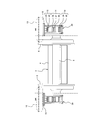
- FIG. 1 is a plan view of a railway vehicle carriage 1 according to a first embodiment of the present invention.
- FIG. 2 is a side view of the railway vehicle carriage 1 shown in FIG.
- FIG. 3 is a cross-sectional view taken along line III-III of the railway vehicle carriage 1 shown in FIG.
- the railcar bogie 1 includes a horizontal beam 4 that extends in the horizontal direction as a vehicle frame 3 for supporting the vehicle body 2. There is no extending side beam.
- a pair of front and rear axles 5 is disposed along the lateral direction in front and rear of the lateral beam 4, and wheels 6 are fixed to both lateral sides of the axle 5.
- Bearings 7 that rotatably support the axle 5 are provided at both lateral ends of the axle 5 so as to be laterally outer than the wheels 6, and the bearings 7 are accommodated in a bearing housing 8.
- An electric motor 11 is attached to the side beam 4.
- An output shaft of the electric motor 11 is connected to a gear box 12 in which a reduction gear that transmits power to the axle 5 is accommodated.
- the electric motor 11 and the gear box 12 are connected with some play and elasticity so that the axle 5 can be slightly displaced with respect to the lateral beam 4.
- the horizontal beam 4 is also provided with a brake device (not shown) for braking the rotation of the wheel 6.
- a plurality of leaf springs 9 extending in the front-rear direction are bridged between the side beam 4 and the bearing housing 8, and the center portion in the front-rear direction of the plate spring 9 is supported at both ends in the lateral direction of the side beam 4. Then, both end portions in the front-rear direction of the leaf spring 9 are supported by the bearing housing 8. That is, a plurality of leaf springs 9 have both the function of a primary suspension and the function of a conventional side beam (the bearing housing 8 is connected to both lateral ends of the lateral beam 4 using only the leaf spring 9. ing.). These plate springs 9 are arranged at intervals below a plurality of middle plate springs 14, a plurality of upper plate springs 15 disposed above the middle plate springs 14 and spaced apart from the middle plate springs 14. And a lower plate spring 16.
- the upper plate spring 15 includes one connecting plate spring 25 whose both ends in the front-rear direction are connected to the bearing housing 8 and one unconnected plate that is not restrained from moving in the front-rear direction.
- the non-connecting plate spring 23 is laminated in surface contact with the upper surface of the connecting plate spring 25.
- the lower plate spring 16 includes one connecting plate spring 26 whose both ends in the front-rear direction are connected to the bearing housing 8 and one non-connecting plate that is not restrained from moving in the front-rear direction.
- the non-connecting plate spring 24 is stacked in surface contact with the upper surface of the connecting plate spring 26.
- the middle plate spring 14 has three non-connecting plate springs 20 to 22 that are not restrained from moving in the front-rear direction at both ends in the front-rear direction, and these non-connecting plate springs 20 to 22 are in surface contact with each other. It is laminated in a state. That is, the middle plate spring 14 is not provided with a connecting plate spring.
- the overall spring constant of the non-connecting leaf springs 20 to 24 is larger than the overall spring constant of the connecting leaf springs 25 and 26.
- the connecting leaf springs 25 and 26 are made of metal, and the non-connecting leaf springs 20 to 24 are made of fiber reinforced resin. However, some or all of the non-connecting leaf springs 20 to 24 may be made of metal.
- each leaf spring 9 is curved in a substantially arc shape so as to protrude upward in a side view when the passenger is not in the vehicle body 2. That is, each leaf spring 9 is formed in a warped state such that both end portions in the front-rear direction are positioned below the center portion in the front-rear direction. Moreover, even when the boarding rate to the vehicle body 2 becomes 100% and the plate spring 9 is bent, the plate spring 9 is maintained in a curved state so as to be convex upward in a side view.
- the spring constant of the whole spring 9 is set.
- the connecting leaf springs 25 and 26 connect the front bearing housing 8 and the rear bearing housing 8, and the front bearing housing 8 and the rear bearing housing 8 are relative to each other in the front-rear direction. Since it is movable, the connecting leaf springs 25 and 26 on the left side of the carriage 1 and the connecting leaf springs 25 and 26 on the right side of the carriage 1 can be elastically deformed with different curvatures according to the load.
- the center portions of the leaf springs 9 in the front-rear direction are positioned and held by a holder 30, and the holders 30 are attached to holder support portions 10 provided at both lateral ends of the side beam 4.
- An air spring 13 that functions as a secondary suspension is placed on the holder support portion 10, and the vehicle body 2 is placed on the air spring 13.
- the lower plate spring 16 is provided with a partial cover 70 that covers the lower plate spring 16 in order to prevent an obstacle (for example, a stepping stone) from hitting it.
- an overall cover 71 that covers the entire bearing housing 8 and the leaf springs 14 to 16 from the outside in the lateral direction may be provided on the carriage 1. According to the entire cover 71, the obstacle countermeasure can be taken and the design of the carriage 1 can be improved.
- FIG. 4 is an enlarged view of a main part of the cross section taken along the line IV-IV in the holder 30 shown in FIG. 2 and its periphery.
- the holder 30 positions and holds the central portions of the plurality of leaf springs 9 in the front-rear direction, and is fixed to the holder support portion 10 of the lateral beam 4 with bolts 32.
- the holder 30 includes a frame portion 43 having an inverted U-shaped cross section that is open at the bottom, a bolt 45 that protrudes downward from the lower end portion of the frame portion 43, and a spacer that is disposed in a space surrounded by the frame portion 43. 33 to 35 and rubber plates 36 to 42, a closing plate 44 through which the lower end of the frame portion 43 is inserted so as to close the lower end opening of the frame portion 43, and a bolt 45 so that the closing plate 44 faces upward. And a nut 46.
- a rubber plate 36, a spacer 33, and a rubber plate 37 are interposed between the upper wall portion of the frame portion 43 and the upper plate spring 15 in this order stacked from above.
- a rubber plate 38, a spacer 34 and a rubber plate 39 are interposed in this order from above, and the middle plate spring 14, the lower plate spring 16, and the like.
- a rubber plate 40, a spacer 35, and a rubber plate 41 are interposed between the lower plate spring 16 and the closing plate 44.
- the rubber plate 42 is interposed between the lower plate spring 16 and the closing plate 44. It is installed.
- the holder 30 holds the plurality of leaf springs 9 at predetermined positions, and the holder 30 and the plurality of leaf springs 9 constitute a subassembly.
- the rubber plate 36 may be omitted.
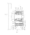
- FIG. 5 is an enlarged view of a main part of the railway vehicle carriage 1 shown in FIG.
- FIG. 6 is a cross-sectional view taken along the line VI-VI of the bearing housing 8 shown in FIG.
- the bearing housing 8 is provided between the axle box 50 that accommodates the bearing 7, the axle box receiver 52 that supports the axle box 50, and between the axle box 50 and the axle box receiver 52.
- a cylindrical rubber block 51 that is an elastic member that is mounted and elastically deformable in the front-rear direction and the lateral direction.
- a clearance is formed between the housing 52 and the housing 50 so that the housing 52 can be displaced in the front-rear direction and the lateral direction with respect to the housing 50.
- the axle box receiver 52 includes a case part 53 that accommodates the axle box 50, and a pair of plate parts that protrude from both lateral sides of the case part 53 toward the center in the front-rear direction of the carriage 1 (left side in FIGS. 5 and 6). 54, and pins 56 to 58 (support portions) made of a columnar metal bridged between the pair of plate portions 54 so as to protrude laterally from the plate portion 54.
- the case portion 53 of the bearing housing 52 accommodates the bearing 7 indirectly by accommodating the housing 50. That is, the shaft box 50 and the case portion 53 constitute a case portion that accommodates the bearing 7 of the bearing housing 8.
- the horizontal interval between the pair of plate portions 54 is set to be slightly larger than the horizontal width of the plate spring 9.
- the pins 56 to 58 are attached to the plate portion 54 at a position where they overlap in a plan view, and are provided at a height that overlaps a height range H between the upper end and the lower end of the case portion 53. Yes.
- the pin 56 and the pin 58 may be arranged so as not to overlap the pins 57 and 58 in a plan view in a state where the pin 57 and the pin 58 overlap in a plan view.
- the pins 56 to 58 may be provided at a height that protrudes upward or downward from the height range H according to design requirements.
- the sleeve 59 includes a cylindrical portion 59a that fits into the pins 57 and 58, and a flange portion 59b that protrudes radially outward from the laterally outer end of the cylindrical portion 59a.
- the flange portion 59b is connected to the sleeve 59a.
- the plate springs 25 and 26 are disposed between the cylinder portions 25 a and 26 a and the plate portion 54. In this way, the cylindrical portions 25a and 26a of the connecting plate springs 25 and 26 are rotatably connected to the pins 57 and 58 with the horizontal direction as the rotation axis, and the pins 57 and 58 are connected to the connecting plate springs 25 and 25, respectively. 26 is supported.
- the middle plate springs 14 are all composed of non-connecting plate springs 20-22.
- the front and rear ends of the lowermost unconnected leaf spring 20 among the middle leaf springs 14 formed of leaf spring groups stacked on each other are supported by the middle pins 56 so as to be movable back and forth. That is, none of the leaf springs 20 to 22 of the middle stage leaf spring 14 is connected to the pin 56.
- the plurality of leaf springs 9 are supported by pins 56 to 58 (support portions) on the center side in the front-rear direction of the carriage 1 with respect to the axle 5. That is, the longitudinal length of the leaf spring 9 is shorter than the distance between the front and rear axles 5.
- the pins 56 to 58 are provided at a height that overlaps a height range H between the upper end and the lower end of the case portion 53 of the bearing housing 8, and the uppermost leaf spring 23 and the lowermost leaf spring 26. The vertical distance between is also short.
- the plate spring 9 is curved in a substantially arc shape so as to protrude upward in a side view, and both end portions in the front-rear direction supported by the pins 56 to 58 of the plate spring 9 are plate springs 9.
- the leaf spring 9 is located below the center part in the front-rear direction supported by the holder 30.
- the leaf spring 9 is elastically deformed so as to approach a straight line in a side view, thereby increasing the distance in the front-rear direction between the front and rear axles 5.
- the entire thickness of the middle plate spring 14 is larger than the total thickness of the upper plate spring 15 and larger than the total thickness of the lower plate spring 16.
- the thickness of each of the non-connecting plate springs 20 to 24 is larger than the thickness of each of the connecting plate springs 25 and 26.
- the leaf spring 9 is supported by the pins 56 to 58 of the bearing housing 8 on the center side in the front-rear direction with respect to the axle 5, so that the length of the leaf spring 9 in the front-rear direction is shortened.
- This makes it possible to achieve a suitable spring constant without increasing the thickness of the leaf spring 9 even when the weight of the vehicle body is large.
- the position where the leaf spring 9 is supported by the bearing housing 8 is not directly below the axle 5 but on the side of the case portion 53 shifted to the center in the front-rear direction with respect to the axle 5. It is possible to prevent the distance between the ground 26 and the ground from being too close, and there is no influence on traveling such as an obstacle coming into contact with the leaf spring 26.
- the position at which the leaf spring 9 is supported by the bearing housing 8 is not directly above the axle 5 but on the side of the case portion 53 that is shifted from the axle 5 toward the center in the front-rear direction.
- the spring 23 can be provided at a low position so that the lateral beam 4 can be lowered, and the vehicle body 2 can be lowered.
- the position of the pin 56 ′ supporting the non-connecting leaf springs 20 to 22 with respect to the axle box receiver 52 ′ is changed from the original position A (the position of the pin 56 in FIG. 5) in the front-rear direction.
- the spring constants of the non-connecting leaf springs 20 to 22 can be changed only by changing the movement without changing other members. For example, if the position of the pin 56 is moved to the center side of the carriage in the front-rear direction, the front-rear direction length of the portion contributing to the elastic force of the middle plate spring 14 is shortened, and the rigidity of the middle plate spring 14 is increased, A spring constant suitable for a cart having a large sprung weight (for example, a cart used for an electric vehicle) is realized.
- the length of the middle plate spring 14 in the front-rear direction becomes longer and the rigidity of the middle plate spring 14 becomes lower.
- a spring constant suitable for a truck with a small sprung weight for example, a truck used in an accompanying car
- the pin position change is not limited to the pin 56 for the middle plate spring 14, but the same effect can be obtained by changing the position of the pin 57 for the upper plate spring 15 and / or the pin 58 for the lower plate spring 16. Obtainable. However, in that case, it is necessary to change the longitudinal length of the connecting leaf springs 25 and 26.
- the leaf springs 25 and 26 curved so as to protrude upward in a side view have a small curvature in a side view when a downward load applied to the center portion in the front-rear direction is increased.
- the longitudinal distance between the front and rear axles 5 increases from the normal distance L0 to the distance L1 (for example, L1-L0 ⁇ 20 mm).
- the plate spring 9 is elastically deformed so that the curvature is increased in side view, and the front-rear distance between the front and rear axles 5 is a distance from the normal distance L0.
- L2 (for example, L0 ⁇ L2 ⁇ 20 mm).
- L2 for example, L0 ⁇ L2 ⁇ 20 mm.
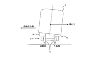
- FIGS. 9 and 10 when the railway vehicle carriage 1 travels along a curve and a centrifugal force acts on the vehicle body 2, the wheel weight of the inner wheel 6 on the curve (inner gauge side) is changed to the inner wheel 6 (outside of the curve).
- the load on the leaf spring 9 on the outer track side becomes larger than the load on the leaf spring 9 on the inner track side. Therefore, the distance L1 between the axles on the outer gauge side is larger than the distance L2 between the axles on the inner gauge side, and the self-steering function of the wheels 6 is exhibited, so that the lateral pressure of the wheels 6 during curve traveling can be reduced, and the curve passing performance is achieved. Will improve.
- the connecting leaf springs 25 and 26 are rotatably supported by the pins 57 and 58, the elastic deformation of the leaf spring 9 becomes smooth.
- the pins 57 and 58 and the cylindrical portions 25a and 26a are made of metal and the sleeve 59 is made of resin, the resistance of the rotational sliding of the cylindrical portions 25a and 26a with respect to the pins 57 and 58 can be reduced.
- the spring constant of the entire leaf spring 9 can be easily adjusted without increasing the thickness of the connecting leaf springs 25 and 26.
- the non-connecting leaf springs 21 to 24 are laminated in surface contact with the upper surfaces of the other leaf springs 20, 21, 25, and 26, the plate springs 9 are in surface contact with each other when the entire leaf spring 9 is bent. Sliding friction is generated between the springs 20 to 26, and an appropriate damping effect can be obtained.
- the overall spring constant of the non-connecting leaf springs 20 to 24 is larger than the overall spring constant of the connecting leaf springs 25 and 26, and the thickness of the connecting leaf springs 25 and 26 is not excessive.
- the workability of the springs 25 and 26 is improved, and the spring constant can be easily adjusted by the non-connecting plate springs 20 to 24.
- the connecting plate springs 25 and 26 are made of metal and the non-connecting plate springs 20 to 24 are made of fiber reinforced resin, the plate springs are improved while improving the workability of the connecting plate springs 25 and 26. The whole 9 can be reduced in weight.
- the middle plate spring 14, the upper plate spring 15 and the lower plate spring 16 are positioned and held by the holder 30 in a state of being spaced apart from each other, the holder 30 and the entire plate spring 9 are modularized. As a result, the assembly workability is improved. Furthermore, since the holder 30 can adjust the force for holding the leaf spring 9 only by adjusting the nut 46, the maintenance of the leaf spring 9 can be facilitated.
- the sleeves fitted around the pins 57 and 58 have a special shape to adjust individual wheel weights in the carriage (required that each wheel weight in the same vehicle be within a certain range).
- the spring constant corresponding to the secular change of the leaf spring may be adjusted.
- the pin holes 25b, 26b of the cylindrical portions 25a, 26a of the connecting leaf springs 25, 26 are increased in diameter, and a sleeve 159 having a pin hole 159a eccentric in the vertical direction is replaced with the cylindrical portion 25a,
- the spring constants of the leaf springs 25 and 26 can be adjusted by adjusting the height of the cylindrical portions 25a and 26a with respect to the pins 57 and 58.
- a locking structure (not shown) may be provided so that the sleeve 159 does not rotate with respect to the cylindrical portions 25a and 26a.
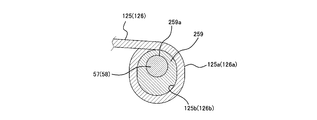
- the cylindrical portions 125a and 126a of the connecting leaf springs 125 and 126 are formed in a vertically long oval shape, and an oval sleeve 259 having a pin hole 259a eccentric in the vertical direction is formed in the cylindrical portion 125a.
- 126a may be adjusted to adjust the spring constants of the leaf springs 125, 126 by adjusting the height of the cylindrical portions 125a, 126a with respect to the pins 57, 58. In this case, the sleeve 259 does not rotate with respect to the cylindrical portions 125a and 126a without providing a locking structure. Further, as shown in FIG.
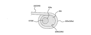
- the cylindrical portions 225a and 226a of the connecting leaf springs 225 and 226 are formed in a horizontally long oval shape, and an oval shape having a pin hole 359a eccentric in the front-rear direction (left and right direction in the figure).
- the sleeve 359 may be inserted into the cylindrical portions 225a and 226a to adjust the front and rear positions of the cylindrical portions 225a and 226a with respect to the pins 57 and 58, thereby adjusting the spring constants of the leaf springs 225 and 226.
- FIG. 14 is a drawing corresponding to FIG. 5 of a railway vehicle bogie according to a second embodiment of the present invention.
- symbol is attached
- the case portion 153 of the bearing housing 108 is divided into two parts in a side view.
- the case portion 153 includes a substantially semicircular first divided body 153A and a second divided body 153B, and the divided bodies 153A and 153B are combined and fastened with a bolt 160 to form a substantially cylindrical shape.
- a case portion 153 is configured.
- the dividing line PL of the case portion 153 is inclined at a predetermined angle ⁇ (for example, 10 ° to 30 °) with respect to the vertical line VL.
- a plate part 154 protrudes from the second divided body 153B on the center side in the front-rear direction of the carriage toward the center side in the front-rear direction, and circular cross-section pins 57 and 58 extending in the lateral direction on the plate part 154 and a cross-section square.
- a shaped support plate 156 is provided.
- the middle plate spring 114 has two non-connecting plate springs 20, 21, and is supported so as to be movable back and forth while both end portions of the lowermost non-connecting plate spring 20 are in surface contact with the support plate 156. Yes.
- the upper plate spring 115 and the lower plate spring 116 have connecting plate springs 25 and 26 and non-connecting plate springs 123 and 124, respectively, and both end portions 123a and 124a of the non-connecting plate springs 123 and 124 are cylindrical portions 25a. , 26a are arcuate. Since other configurations are the same as those of the first embodiment described above, detailed description thereof is omitted.
- FIG. 15 is a side view of a railway vehicle carriage 201 according to the third embodiment of the present invention.
- symbol is attached
- the carriage 201 of this embodiment is provided with holders 230 that hold a plurality of leaf springs 209 at both lateral ends of the transverse beam 204 of the carriage frame from which side beams are omitted.
- 209 includes one connecting leaf spring 220 and a plurality of non-connecting leaf springs 221 to 224 stacked thereon.
- the leaf springs 220 to 224 are curved in a substantially arc shape so as to protrude upward in a side view, and the length in the front-rear direction gradually decreases toward the upper layer, and both end portions in the front-rear direction are stepped. Is formed. Both end portions 220 a of the connecting plate spring 220 are connected to the bearing housing 208.
- the case portion 253 of the bearing housing 208 is vertically divided into two in a side view.
- the case portion 253 includes a substantially semicircular lower divided body 253A and an upper divided body 253B, and these divided bodies 253A and 253B are combined and fastened with bolts 260 and 261 to form a substantially cylindrical shape.
- the case portion 253 is configured.
- a support plate 254 protrudes from the lower divided body 253A toward the center in the front-rear direction, and both end portions 220a of the connecting plate spring 220 are supported by the support plate 254.
- the support plate 254 is located on the center side in the front-rear direction from the axle 5 and is provided at a height that overlaps the height range between the upper end and the lower end of the case portion 253.
- the railcar bogie according to the present invention has an excellent effect of optimizing the spring constant of the leaf spring, and it is beneficial to be widely applied to railcars that can demonstrate the significance of this effect.
Abstract
Description
図1は、本発明の第1実施形態に係る鉄道車両用台車1の平面図である。図2は、図1に示す鉄道車両用台車1の側面図である。図3は、図1に示す鉄道車両用台車1のIII-III線断面図である。図1~3に示すように、鉄道車両用台車1は、車体2を支持するための台車枠3として横方向に延びる横ばり4を備えているが、横ばり4の両端部から前後方向に延びる側ばりを備えていない。横ばり4の前方及び後方には、横方向に沿って前後一対の車軸5が配置されており、車軸5の横方向両側には車輪6が固定されている。車軸5の横方向両端部には、車輪6よりも横方向外側にて車軸5を回転自在に支持する軸受7が設けられ、その軸受7は軸受収容体8に収容されている。横ばり4には、電動機11が取り付けられており、その電動機11の出力軸には、車軸5に動力を伝達する減速ギヤが収容されたギヤボックス12が接続されている。なお、電動機11とギヤボックス12とは、車軸5が横ばり4に対して若干変位できるように若干の遊びや弾性をもって接続されている。また、横ばり4には、車輪6の回転を制動するためのブレーキ装置(図示せず)も設けられている。 (First embodiment)
FIG. 1 is a plan view of a
図14は、本発明の第2実施形態に係る鉄道車両用台車の図5相当の図面である。なお、第1実施形態と共通する構成については同一符号を付して説明を省略する。図14に示すように、本実施形態の台車では、軸受収容体108のケース部153が側面視で二分割されている。具体的には、ケース部153は、それぞれ略半円状の第1分割体153A及び第2分割体153Bを備え、これら分割体153A,153Bを合わせてボルト160で締結することで略円筒状のケース部153が構成される。ケース部153の分割線PLは、鉛直線VLに対して所定角θ(例えば、10°~30°)で傾斜している。 (Second Embodiment)
FIG. 14 is a drawing corresponding to FIG. 5 of a railway vehicle bogie according to a second embodiment of the present invention. In addition, about the structure which is common in 1st Embodiment, the same code | symbol is attached | subjected and description is abbreviate | omitted. As shown in FIG. 14, in the cart of this embodiment, the
図15は、本発明の第3実施形態に係る鉄道車両用台車201の側面図である。なお、第1実施形態と共通する構成については同一符号を付して説明を省略する。図15に示すように、本実施形態の台車201は、側ばりを省略した台車枠の横ばり204の横方向両端部に複数の板バネ209を保持するホルダ230が取り付けられており、板バネ209は、1つの連結用板バネ220と、それに積層された複数の非連結用板バネ221~224とからなる。板バネ220~224は、側面視で上方に向けて凸となるように略円弧状に湾曲しており、上層にいくにつれて前後方向の長さが漸減するようにして前後方向両端部を階段状に形成している。連結用板バネ220の両端部220aは、軸受収容体208に連結されている。軸受収容体208のケース部253は、側面視で上下に二分割されている。 (Third embodiment)
FIG. 15 is a side view of a
2 車体
4 横ばり
5 車軸
7 軸受
8 軸受収容体
9 板バネ
14 中段板バネ
15 上段板バネ
16 下段板バネ
20~24 非連結用板バネ
25,26 連結用板バネ
25a,26a 筒部
25b,26b ピン孔
30 ホルダ
50 軸箱
51 ゴムブロック(弾性部材)
52 軸箱受け
53 ケース部
54 板部
56~58 ピン(支持部)
59 スリーブ DESCRIPTION OF
52
59 sleeve
Claims (16)
- 鉄道車両の車体を支持するための横ばりと、
前記横ばりの前方及び後方において横方向に沿って配置された前後一対の車軸と、
前記車軸の横方向両側に設けられて、前記車軸を回転自在に支持する軸受と、
前記軸受を収容する軸受収容体と、
前記横ばりの横方向の両端部に支持された状態で前後方向に延びて、その端部が前記軸受収容体に支持された板バネと、を備え、
前記軸受収容体は、前記軸受を収容するケース部と、前記板バネを支持する支持部とを有し、前記板バネは、前記車軸よりも前後方向中央側にて前記支持部に支持されている、鉄道車両用台車。 A side to support the body of the railway vehicle,
A pair of front and rear axles arranged along the lateral direction at the front and rear of the side beam;
Bearings provided on both lateral sides of the axle, and rotatably supporting the axle;
A bearing housing for housing the bearing;
A leaf spring that extends in the front-rear direction in a state of being supported at both lateral ends of the lateral beam, and whose end is supported by the bearing housing,
The bearing housing includes a case portion that accommodates the bearing and a support portion that supports the leaf spring, and the leaf spring is supported by the support portion on the center side in the front-rear direction with respect to the axle. There is a bogie for rail cars. - 前記板バネのうち前記支持部に支持される部位は、前記板バネのうち前記横ばりに支持される部位よりも下方に位置している、請求項1に記載の鉄道車両用台車。 The railway vehicle carriage according to claim 1, wherein a portion of the leaf spring supported by the support portion is located below a portion of the leaf spring supported by the lateral beam.
- 前記板バネは、その前後方向における中央部が前記横ばりに支持され、その前後方向における両端部が前記支持部に支持され、
前記板バネは、側面視で上方に向けて凸となるように略円弧状に湾曲している、請求項2に記載の鉄道車両用台車。 The leaf spring has a central portion in the front-rear direction supported by the lateral beam, and both end portions in the front-rear direction are supported by the support portion,
The bogie for a railway vehicle according to claim 2, wherein the leaf spring is curved in a substantially arc shape so as to protrude upward in a side view. - 前記板バネは、前側の前記軸受収容体と後側の前記軸受収容体とを連結する連結用板バネを有し、
前記前側の軸受収容体と前記後側の軸受収容体との間の距離が、前記連結用板バネの荷重に応じた弾性変形により変化する、請求項2又は3に記載の鉄道車両用台車。 The leaf spring has a connecting leaf spring for connecting the bearing housing body on the front side and the bearing housing body on the rear side,
4. The railcar bogie according to claim 2, wherein a distance between the front bearing housing and the rear bearing housing changes due to elastic deformation according to a load of the connecting leaf spring. 5. - 前記板バネは、連結用板バネを有し、
前記連結用板バネの両端部は、横方向を回動軸線として回動自在に前記支持部に連結支持されている、請求項1乃至4のいずれかに記載の鉄道車両用台車。 The leaf spring has a connecting leaf spring,
The bogie for a railway vehicle according to any one of claims 1 to 4, wherein both end portions of the connecting plate spring are connected and supported by the support portion so as to be rotatable about a horizontal direction as a rotation axis. - 前記連結用板バネの前記両端部には、折り返すように湾曲してピン孔を形成する筒部が設けられ、
前記軸受収容体は、前記ケース部から前記台車の前後方向中央側に突出する板部をさらに有し、
前記支持部は、前記板部から横方向に突出するピンを有し、
前記ピンが前記ピン孔に回動自在に挿入されることで、前記連結用板バネの前記両端部が前記支持部に連結支持されている、請求項5に記載の鉄道車両用台車。 Cylindrical portions that are bent so as to be folded back to form pin holes are provided at the both ends of the connecting leaf spring,
The bearing housing further includes a plate portion projecting from the case portion toward the front-rear direction center side of the carriage,
The support part has a pin that protrudes laterally from the plate part,
The bogie for a railway vehicle according to claim 5, wherein the both ends of the connecting plate spring are connected and supported by the support portion by the pin being rotatably inserted into the pin hole. - 前記ピンと前記筒部との間には、スリーブが介装されており、
前記ピン及び前記筒部は金属からなり、前記スリーブは樹脂からなる、請求項6に記載の鉄道車両用台車。 A sleeve is interposed between the pin and the cylindrical portion,
The bogie for a railway vehicle according to claim 6, wherein the pin and the cylindrical portion are made of metal, and the sleeve is made of resin. - 前記板バネは、その端部が前後方向に拘束されていない非連結用板バネをさらに有している、請求項4乃至7のいずれかに記載の鉄道車両用台車。 The railcar bogie according to any one of claims 4 to 7, wherein the leaf spring further includes a non-connecting leaf spring whose end is not restrained in the front-rear direction.
- 前記非連結用板バネのうち少なくとも1つは、前記連結用板バネと上下に間隔をあけて配置され、その端部が前記支持部に前後移動自在に支持されている、請求項8に記載の鉄道車両用台車。 The at least one of the non-connecting leaf springs is disposed at a distance from the connecting leaf spring in the vertical direction, and an end portion thereof is supported by the support portion so as to be movable back and forth. Trolley car trolley.
- 前記非連結用板バネのうち少なくとも1つは、前記連結用板バネの上面に面接触して積層されている、請求項8又は9に記載の鉄道車両用台車。 10. The railcar bogie according to claim 8 or 9, wherein at least one of the non-connecting leaf springs is laminated in surface contact with an upper surface of the connecting leaf spring.
- 前記非連結用板バネの全体のバネ定数は、前記連結用板バネの全体のバネ定数よりも大きい、請求項8乃至10のいずれかに記載の鉄道車両用台車。 11. The bogie for a railway vehicle according to claim 8, wherein an overall spring constant of the non-connecting leaf spring is larger than an overall spring constant of the connecting leaf spring.
- 前記連結用板バネは、金属からなり、
前記非連結用板バネは、繊維強化樹脂からなる板バネを含んでいる、請求項8乃至11のいずれかに記載の鉄道車両用台車。 The connecting leaf spring is made of metal,
The railcar bogie according to any one of claims 8 to 11, wherein the non-connecting leaf spring includes a leaf spring made of fiber reinforced resin. - 前記板バネは、互いに上下に間隔をあけた複数の板バネを有し、
前記複数の板バネには、それらの前後方向における中央部をまとめて位置決め保持するホルダが取り付けられ、
前記ホルダが、前記横ばりの前記両端部に固定されている、請求項1乃至12のいずれかに記載の鉄道車両用台車。 The leaf spring has a plurality of leaf springs spaced apart from each other vertically,
The plurality of leaf springs are attached with a holder for positioning and holding the central portions in the front-rear direction,
The bogie for railway vehicles according to any one of claims 1 to 12, wherein the holder is fixed to the both end portions of the side beam. - 前記板バネは、中段板バネと、前記中段板バネの上方に間隔をあけて配置された上段板バネと、前記中段板バネの下方に間隔をあけて配置された下段板バネとを有し、
前記上段板バネ及び前記下段板バネは、少なくとも前記連結用板バネを含み、
前記中段板バネは、前記非連結用板バネからなる、請求項8乃至13のいずれかに記載の鉄道車両用台車。 The leaf spring includes a middle leaf spring, an upper leaf spring disposed above the middle leaf spring, and a lower leaf spring disposed below the middle leaf spring. ,
The upper plate spring and the lower plate spring include at least the connecting plate spring,
The bogie for a railway vehicle according to any one of claims 8 to 13, wherein the middle plate spring comprises the non-connecting plate spring. - 前記軸受収容体は、前記軸受を収容する軸箱と、前記軸箱を支持する軸箱受けと、前記軸箱と前記軸箱受けとの間に介装されて前後方向及び横方向に弾性変形可能な弾性部材とを備えている、請求項1乃至14のいずれかに記載の鉄道車両用台車。 The bearing housing is interposed between the axle box that accommodates the bearing, the axle box support that supports the axle box, and the axle box and the axle box receiver, and is elastically deformed in the front-rear direction and the lateral direction. The bogie for railway vehicles according to any one of claims 1 to 14, comprising a possible elastic member.
- 前記支持部は、前記ケース部の上端から下端までの間の高さ範囲に重なる高さに設けられている、請求項1乃至15のいずれかに記載の鉄道車両用台車。 The railway vehicle carriage according to any one of claims 1 to 15, wherein the support portion is provided at a height that overlaps a height range between an upper end and a lower end of the case portion.
Priority Applications (7)
| Application Number | Priority Date | Filing Date | Title |
|---|---|---|---|
| PCT/JP2011/002072 WO2012137257A1 (en) | 2011-04-07 | 2011-04-07 | Railway bogie |
| KR1020127016613A KR101347310B1 (en) | 2011-04-07 | 2011-04-07 | Railcar bogie |
| CN201180040186.8A CN103052554B (en) | 2011-04-07 | 2011-04-07 | Railcar bogie |
| JP2012521810A JP5433080B2 (en) | 2011-04-07 | 2011-04-07 | Railcar bogie |
| EP11863099.5A EP2695791B1 (en) | 2011-04-07 | 2011-04-07 | Railway bogie |
| US13/501,190 US8656839B2 (en) | 2011-04-07 | 2011-04-07 | Railcar bogie |
| TW100119537A TWI421183B (en) | 2011-04-07 | 2011-06-03 | Railway vehicles with trolleys |
Applications Claiming Priority (1)
| Application Number | Priority Date | Filing Date | Title |
|---|---|---|---|
| PCT/JP2011/002072 WO2012137257A1 (en) | 2011-04-07 | 2011-04-07 | Railway bogie |
Publications (1)
| Publication Number | Publication Date |
|---|---|
| WO2012137257A1 true WO2012137257A1 (en) | 2012-10-11 |
Family
ID=46968702
Family Applications (1)
| Application Number | Title | Priority Date | Filing Date |
|---|---|---|---|
| PCT/JP2011/002072 WO2012137257A1 (en) | 2011-04-07 | 2011-04-07 | Railway bogie |
Country Status (7)
| Country | Link |
|---|---|
| US (1) | US8656839B2 (en) |
| EP (1) | EP2695791B1 (en) |
| JP (1) | JP5433080B2 (en) |
| KR (1) | KR101347310B1 (en) |
| CN (1) | CN103052554B (en) |
| TW (1) | TWI421183B (en) |
| WO (1) | WO2012137257A1 (en) |
Cited By (7)
| Publication number | Priority date | Publication date | Assignee | Title |
|---|---|---|---|---|
| JP2014088176A (en) * | 2011-07-14 | 2014-05-15 | Kawasaki Heavy Ind Ltd | Truck for railroad vehicle |
| JP2014172437A (en) * | 2013-03-06 | 2014-09-22 | Kawasaki Heavy Ind Ltd | Steering truck of parallel cardan driving system |
| WO2014203450A1 (en) * | 2013-06-19 | 2014-12-24 | 川崎重工業株式会社 | Leaf spring cover and rail car carriage provided with same |
| JP2016113064A (en) * | 2014-12-17 | 2016-06-23 | 川崎重工業株式会社 | Truck for railroad vehicle |
| US9688292B2 (en) | 2013-04-24 | 2017-06-27 | Kawasaki Jukogyo Kabushiki Kaisha | Railcar bogie |
| WO2017110042A1 (en) * | 2015-12-25 | 2017-06-29 | 川崎重工業株式会社 | Bogie for railway vehicle |
| WO2018203367A1 (en) * | 2017-05-01 | 2018-11-08 | 川崎重工業株式会社 | Railway vehicle bogie provided with protective film and leaf spring provided with protective film |
Families Citing this family (17)
| Publication number | Priority date | Publication date | Assignee | Title |
|---|---|---|---|---|
| USD749984S1 (en) * | 2012-05-15 | 2016-02-23 | Kawasaki Jukogyo Kabushiki Kaisha | Bogie for railcar |
| CN102963388B (en) * | 2012-07-10 | 2015-06-24 | 南车南京浦镇车辆有限公司 | Flexible direct-drive type steering rack |
| US9090296B2 (en) * | 2013-08-29 | 2015-07-28 | Deere & Company | Resilient track frame pivot mechanism |
| JP6247494B2 (en) * | 2013-10-09 | 2017-12-13 | 川崎重工業株式会社 | Method for manufacturing leaf spring for railway vehicle bogie |
| CN104527698A (en) * | 2014-12-17 | 2015-04-22 | 济南轨道交通装备有限责任公司 | Radial device of plate-spring-type bogie |
| JP6506630B2 (en) * | 2015-06-03 | 2019-04-24 | 川崎重工業株式会社 | Leaf spring unit and truck for railway vehicle |
| JP6944765B2 (en) * | 2016-05-16 | 2021-10-06 | 川崎重工業株式会社 | Assembling method of railroad car bogie, measuring jig and railroad car bogie |
| DE102016123784A1 (en) | 2016-12-08 | 2018-06-14 | CG Rail - Chinesisch-Deutsches Forschungs- und Entwicklungszentrum für Bahn- und Verkehrstechnik Dresden GmbH | Bogie of a rail vehicle with at least two axles mounted in axle bearings and at least one cross member |
| CN111348066B (en) * | 2018-12-20 | 2021-07-30 | 中车唐山机车车辆有限公司 | Framework, bogie and rail vehicle |
| CN112298254B (en) * | 2019-08-02 | 2022-05-17 | 中车唐山机车车辆有限公司 | Installation foundation device of bogie |
| CN112298253B (en) * | 2019-08-02 | 2022-05-17 | 中车唐山机车车辆有限公司 | Side beam of bogie |
| CN112298251B (en) * | 2019-08-02 | 2022-07-26 | 中车唐山机车车辆有限公司 | Steering frame |
| CN112644541B (en) * | 2019-10-10 | 2022-07-26 | 中车唐山机车车辆有限公司 | Primary suspension device, bogie and rail vehicle |
| CN111232009B (en) * | 2020-01-17 | 2022-04-08 | 中车株洲电力机车有限公司 | Side beam, framework and bogie |
| DE102020109930A1 (en) | 2020-04-09 | 2021-10-14 | CG Rail - Chinesisch-Deutsches Forschungs- und Entwicklungszentrum für Bahn- und Verkehrstechnik Dresden GmbH | Bogie for a rail vehicle with anti-roll support |
| CN111959550A (en) * | 2020-08-24 | 2020-11-20 | 中车株洲电力机车有限公司 | Framework and bogie thereof |
| DE102020133694B3 (en) | 2020-12-16 | 2022-05-05 | CG Rail - Chinesisch-Deutsches Forschungs- und Entwicklungszentrum für Bahn- und Verkehrstechnik Dresden GmbH | Arrangement of a kinematic package and a spring lever for a bogie |
Citations (11)
| Publication number | Priority date | Publication date | Assignee | Title |
|---|---|---|---|---|
| JPS4940801B1 (en) * | 1970-04-14 | 1974-11-05 | ||
| JPS5547950A (en) | 1978-09-27 | 1980-04-05 | Sumitomo Metal Ind | Truck for railway rolling stock that side beam is omitted |
| JPS55161754U (en) * | 1979-05-11 | 1980-11-20 | ||
| JPS56152763U (en) * | 1980-04-14 | 1981-11-16 | ||
| JPH01168562A (en) * | 1987-12-23 | 1989-07-04 | Railway Technical Res Inst | Truck for rolling stock |
| JPH04119266U (en) * | 1991-04-01 | 1992-10-26 | 日本車輌製造株式会社 | Railway vehicle trolley |
| EP0601677A1 (en) * | 1992-12-08 | 1994-06-15 | INSTITUT FÜR SCHIENENFAHRZEUGE GmbH | Twin axle drive |
| JP2799078B2 (en) | 1991-01-24 | 1998-09-17 | 川崎重工業株式会社 | Axle box support device |
| JP2000502974A (en) * | 1997-07-24 | 2000-03-14 | アーベーベー・ダイムラー―ベンツ・トランスポルタツイオーン(テクノロジー)・ゲゼルシャフト・ミト・ベシュレンクテル・ハフツング | Track device traveling equipment |
| WO2001032490A1 (en) * | 1999-11-03 | 2001-05-10 | Schaefer Enkeler Andreas | Bogie for rail vehicles |
| US6305297B1 (en) * | 1998-06-18 | 2001-10-23 | Alstom Transport Sa | Railway vehicle bogie and process for manufacturing a side member of such a bogie |
Family Cites Families (9)
| Publication number | Priority date | Publication date | Assignee | Title |
|---|---|---|---|---|
| US1508954A (en) * | 1922-03-07 | 1924-09-16 | Broussouse Fernand Louis | Bogie for rolling stock |
| DE601713C (en) | 1932-02-06 | 1934-08-25 | Ettore Bugatti | Bogie with at least three axles for rail vehicles |
| GB1307268A (en) * | 1970-08-05 | 1973-02-14 | British Leyland Truck & Bus | Bogie suspensions |
| US3945325A (en) * | 1971-06-04 | 1976-03-23 | Swiss Aluminium Ltd. | Railway bogie |
| JPS58124840A (en) * | 1982-01-22 | 1983-07-25 | Toho Rayon Co Ltd | Laminated spring |
| US4487133A (en) * | 1982-09-24 | 1984-12-11 | The Budd Company | Primary suspension system for providing low vertical and longitudinal spring rates in a railway cap |
| JPH07102810B2 (en) * | 1987-09-16 | 1995-11-08 | 株式会社日立製作所 | Railcar axle box support device |
| US20040084822A1 (en) * | 2002-11-05 | 2004-05-06 | Collyer Brent R. | Bushing with performance tuning features |
| CN101659264B (en) * | 2009-09-18 | 2011-07-20 | 武桥重工集团股份有限公司 | Plate-spring straddle-type four-shaft steering rack used for railway crane |
-
2011
- 2011-04-07 US US13/501,190 patent/US8656839B2/en not_active Expired - Fee Related
- 2011-04-07 WO PCT/JP2011/002072 patent/WO2012137257A1/en active Application Filing
- 2011-04-07 KR KR1020127016613A patent/KR101347310B1/en active IP Right Grant
- 2011-04-07 CN CN201180040186.8A patent/CN103052554B/en not_active Expired - Fee Related
- 2011-04-07 EP EP11863099.5A patent/EP2695791B1/en active Active
- 2011-04-07 JP JP2012521810A patent/JP5433080B2/en not_active Expired - Fee Related
- 2011-06-03 TW TW100119537A patent/TWI421183B/en not_active IP Right Cessation
Patent Citations (11)
| Publication number | Priority date | Publication date | Assignee | Title |
|---|---|---|---|---|
| JPS4940801B1 (en) * | 1970-04-14 | 1974-11-05 | ||
| JPS5547950A (en) | 1978-09-27 | 1980-04-05 | Sumitomo Metal Ind | Truck for railway rolling stock that side beam is omitted |
| JPS55161754U (en) * | 1979-05-11 | 1980-11-20 | ||
| JPS56152763U (en) * | 1980-04-14 | 1981-11-16 | ||
| JPH01168562A (en) * | 1987-12-23 | 1989-07-04 | Railway Technical Res Inst | Truck for rolling stock |
| JP2799078B2 (en) | 1991-01-24 | 1998-09-17 | 川崎重工業株式会社 | Axle box support device |
| JPH04119266U (en) * | 1991-04-01 | 1992-10-26 | 日本車輌製造株式会社 | Railway vehicle trolley |
| EP0601677A1 (en) * | 1992-12-08 | 1994-06-15 | INSTITUT FÜR SCHIENENFAHRZEUGE GmbH | Twin axle drive |
| JP2000502974A (en) * | 1997-07-24 | 2000-03-14 | アーベーベー・ダイムラー―ベンツ・トランスポルタツイオーン(テクノロジー)・ゲゼルシャフト・ミト・ベシュレンクテル・ハフツング | Track device traveling equipment |
| US6305297B1 (en) * | 1998-06-18 | 2001-10-23 | Alstom Transport Sa | Railway vehicle bogie and process for manufacturing a side member of such a bogie |
| WO2001032490A1 (en) * | 1999-11-03 | 2001-05-10 | Schaefer Enkeler Andreas | Bogie for rail vehicles |
Cited By (12)
| Publication number | Priority date | Publication date | Assignee | Title |
|---|---|---|---|---|
| JP2014088176A (en) * | 2011-07-14 | 2014-05-15 | Kawasaki Heavy Ind Ltd | Truck for railroad vehicle |
| JP2014172437A (en) * | 2013-03-06 | 2014-09-22 | Kawasaki Heavy Ind Ltd | Steering truck of parallel cardan driving system |
| EP2965966A4 (en) * | 2013-03-06 | 2016-12-14 | Kawasaki Heavy Ind Ltd | Parallel cardan drive-type steering bogie |
| US9902407B2 (en) | 2013-03-06 | 2018-02-27 | Kawasaki Jukogyo Kabushiki Kaisha | Parallel cardan driving system steering bogie |
| US9688292B2 (en) | 2013-04-24 | 2017-06-27 | Kawasaki Jukogyo Kabushiki Kaisha | Railcar bogie |
| WO2014203450A1 (en) * | 2013-06-19 | 2014-12-24 | 川崎重工業株式会社 | Leaf spring cover and rail car carriage provided with same |
| JP2015003559A (en) * | 2013-06-19 | 2015-01-08 | 川崎重工業株式会社 | Plate spring cover and railway vehicle truck with the same |
| JP2016113064A (en) * | 2014-12-17 | 2016-06-23 | 川崎重工業株式会社 | Truck for railroad vehicle |
| WO2017110042A1 (en) * | 2015-12-25 | 2017-06-29 | 川崎重工業株式会社 | Bogie for railway vehicle |
| WO2018203367A1 (en) * | 2017-05-01 | 2018-11-08 | 川崎重工業株式会社 | Railway vehicle bogie provided with protective film and leaf spring provided with protective film |
| CN110891842A (en) * | 2017-05-01 | 2020-03-17 | 川崎重工业株式会社 | Railway vehicle bogie with protective film and plate spring with protective film |
| CN110891842B (en) * | 2017-05-01 | 2022-04-29 | 川崎重工业株式会社 | Railway vehicle bogie with protective film and plate spring with protective film |
Also Published As
| Publication number | Publication date |
|---|---|
| US20120279416A1 (en) | 2012-11-08 |
| US8656839B2 (en) | 2014-02-25 |
| JP5433080B2 (en) | 2014-03-05 |
| EP2695791A1 (en) | 2014-02-12 |
| CN103052554B (en) | 2016-02-03 |
| CN103052554A (en) | 2013-04-17 |
| TWI421183B (en) | 2014-01-01 |
| TW201240855A (en) | 2012-10-16 |
| KR20120132470A (en) | 2012-12-05 |
| JPWO2012137257A1 (en) | 2014-07-28 |
| KR101347310B1 (en) | 2014-01-15 |
| EP2695791A4 (en) | 2015-03-25 |
| EP2695791B1 (en) | 2020-05-13 |
Similar Documents
| Publication | Publication Date | Title |
|---|---|---|
| JP5433080B2 (en) | Railcar bogie | |
| JP5883488B2 (en) | Railcar bogie | |
| JP6703965B2 (en) | Electric truck drive | |
| CN111994120B (en) | Rail vehicle | |
| CN102414070B (en) | Low-floor rolling stock and low-floor rolling stock provided therewith | |
| WO2014174787A1 (en) | Railway vehicle truck | |
| JP6034254B2 (en) | Railcar bogie | |
| KR101867446B1 (en) | Bogie for railway vehicle | |
| WO2015056560A1 (en) | Travel carriage, and vehicle for track-based transport system | |
| CN111994114B (en) | Framework, bogie and rail vehicle | |
| WO2015079734A1 (en) | Vehicular suspension device, traveling truck, and vehicle | |
| JPH043347B2 (en) | ||
| JP2015009572A (en) | Carriage for railway vehicle | |
| JP2018076031A (en) | Axle box suspension for railway vehicle | |
| CN111994113B (en) | Bogie and rail vehicle | |
| JP5180143B2 (en) | Railcar bogie | |
| CN111376940B (en) | Bogie assembly, rail vehicle and rail transit system | |
| CN111994115B (en) | Steering frame | |
| JP5869403B2 (en) | Railway vehicle carriage and method of manufacturing the same | |
| CN112455243B (en) | Trolley bus running system and trolley bus | |
| CN111196289B (en) | Bogie and rail vehicle | |
| CN205930745U (en) | Steering frame | |
| JP2023159783A (en) | Railway vehicle bogie | |
| JP2017024536A (en) | Truck for railway vehicle | |
| JP2019034582A (en) | On-board element support device for railway vehicle and truck unit provided with the same |
Legal Events
| Date | Code | Title | Description |
|---|---|---|---|
| WWE | Wipo information: entry into national phase |
Ref document number: 201180040186.8 Country of ref document: CN |
|
| WWE | Wipo information: entry into national phase |
Ref document number: 13501190 Country of ref document: US |
|
| ENP | Entry into the national phase |
Ref document number: 2012521810 Country of ref document: JP Kind code of ref document: A |
|
| ENP | Entry into the national phase |
Ref document number: 20127016613 Country of ref document: KR Kind code of ref document: A |
|
| 121 | Ep: the epo has been informed by wipo that ep was designated in this application |
Ref document number: 11863099 Country of ref document: EP Kind code of ref document: A1 |
|
| NENP | Non-entry into the national phase |
Ref country code: DE |
|
| WWE | Wipo information: entry into national phase |
Ref document number: 2011863099 Country of ref document: EP |