WO2012137247A1 - Internal combustion engine equipped with burner apparatus - Google Patents
Internal combustion engine equipped with burner apparatus Download PDFInfo
- Publication number
- WO2012137247A1 WO2012137247A1 PCT/JP2011/002014 JP2011002014W WO2012137247A1 WO 2012137247 A1 WO2012137247 A1 WO 2012137247A1 JP 2011002014 W JP2011002014 W JP 2011002014W WO 2012137247 A1 WO2012137247 A1 WO 2012137247A1
- Authority
- WO
- WIPO (PCT)
- Prior art keywords
- exhaust gas
- fuel
- exhaust
- catalyst
- fuel supply
- Prior art date
Links
Images


Classifications
-
- F—MECHANICAL ENGINEERING; LIGHTING; HEATING; WEAPONS; BLASTING
- F01—MACHINES OR ENGINES IN GENERAL; ENGINE PLANTS IN GENERAL; STEAM ENGINES
- F01N—GAS-FLOW SILENCERS OR EXHAUST APPARATUS FOR MACHINES OR ENGINES IN GENERAL; GAS-FLOW SILENCERS OR EXHAUST APPARATUS FOR INTERNAL COMBUSTION ENGINES
- F01N3/00—Exhaust or silencing apparatus having means for purifying, rendering innocuous, or otherwise treating exhaust
- F01N3/02—Exhaust or silencing apparatus having means for purifying, rendering innocuous, or otherwise treating exhaust for cooling, or for removing solid constituents of, exhaust
- F01N3/021—Exhaust or silencing apparatus having means for purifying, rendering innocuous, or otherwise treating exhaust for cooling, or for removing solid constituents of, exhaust by means of filters
- F01N3/023—Exhaust or silencing apparatus having means for purifying, rendering innocuous, or otherwise treating exhaust for cooling, or for removing solid constituents of, exhaust by means of filters using means for regenerating the filters, e.g. by burning trapped particles
- F01N3/025—Exhaust or silencing apparatus having means for purifying, rendering innocuous, or otherwise treating exhaust for cooling, or for removing solid constituents of, exhaust by means of filters using means for regenerating the filters, e.g. by burning trapped particles using fuel burner or by adding fuel to exhaust
-
- F—MECHANICAL ENGINEERING; LIGHTING; HEATING; WEAPONS; BLASTING
- F01—MACHINES OR ENGINES IN GENERAL; ENGINE PLANTS IN GENERAL; STEAM ENGINES
- F01N—GAS-FLOW SILENCERS OR EXHAUST APPARATUS FOR MACHINES OR ENGINES IN GENERAL; GAS-FLOW SILENCERS OR EXHAUST APPARATUS FOR INTERNAL COMBUSTION ENGINES
- F01N3/00—Exhaust or silencing apparatus having means for purifying, rendering innocuous, or otherwise treating exhaust
- F01N3/02—Exhaust or silencing apparatus having means for purifying, rendering innocuous, or otherwise treating exhaust for cooling, or for removing solid constituents of, exhaust
- F01N3/021—Exhaust or silencing apparatus having means for purifying, rendering innocuous, or otherwise treating exhaust for cooling, or for removing solid constituents of, exhaust by means of filters
- F01N3/033—Exhaust or silencing apparatus having means for purifying, rendering innocuous, or otherwise treating exhaust for cooling, or for removing solid constituents of, exhaust by means of filters in combination with other devices
- F01N3/035—Exhaust or silencing apparatus having means for purifying, rendering innocuous, or otherwise treating exhaust for cooling, or for removing solid constituents of, exhaust by means of filters in combination with other devices with catalytic reactors, e.g. catalysed diesel particulate filters
-
- F—MECHANICAL ENGINEERING; LIGHTING; HEATING; WEAPONS; BLASTING
- F01—MACHINES OR ENGINES IN GENERAL; ENGINE PLANTS IN GENERAL; STEAM ENGINES
- F01N—GAS-FLOW SILENCERS OR EXHAUST APPARATUS FOR MACHINES OR ENGINES IN GENERAL; GAS-FLOW SILENCERS OR EXHAUST APPARATUS FOR INTERNAL COMBUSTION ENGINES
- F01N3/00—Exhaust or silencing apparatus having means for purifying, rendering innocuous, or otherwise treating exhaust
- F01N3/08—Exhaust or silencing apparatus having means for purifying, rendering innocuous, or otherwise treating exhaust for rendering innocuous
- F01N3/10—Exhaust or silencing apparatus having means for purifying, rendering innocuous, or otherwise treating exhaust for rendering innocuous by thermal or catalytic conversion of noxious components of exhaust
- F01N3/18—Exhaust or silencing apparatus having means for purifying, rendering innocuous, or otherwise treating exhaust for rendering innocuous by thermal or catalytic conversion of noxious components of exhaust characterised by methods of operation; Control
- F01N3/20—Exhaust or silencing apparatus having means for purifying, rendering innocuous, or otherwise treating exhaust for rendering innocuous by thermal or catalytic conversion of noxious components of exhaust characterised by methods of operation; Control specially adapted for catalytic conversion ; Methods of operation or control of catalytic converters
- F01N3/2006—Periodically heating or cooling catalytic reactors, e.g. at cold starting or overheating
- F01N3/2033—Periodically heating or cooling catalytic reactors, e.g. at cold starting or overheating using a fuel burner or introducing fuel into exhaust duct
-
- F—MECHANICAL ENGINEERING; LIGHTING; HEATING; WEAPONS; BLASTING
- F01—MACHINES OR ENGINES IN GENERAL; ENGINE PLANTS IN GENERAL; STEAM ENGINES
- F01N—GAS-FLOW SILENCERS OR EXHAUST APPARATUS FOR MACHINES OR ENGINES IN GENERAL; GAS-FLOW SILENCERS OR EXHAUST APPARATUS FOR INTERNAL COMBUSTION ENGINES
- F01N2340/00—Dimensional characteristics of the exhaust system, e.g. length, diameter or volume of the apparatus; Spatial arrangements of exhaust apparatuses
- F01N2340/02—Dimensional characteristics of the exhaust system, e.g. length, diameter or volume of the apparatus; Spatial arrangements of exhaust apparatuses characterised by the distance of the apparatus to the engine, or the distance between two exhaust treating apparatuses
-
- F—MECHANICAL ENGINEERING; LIGHTING; HEATING; WEAPONS; BLASTING
- F01—MACHINES OR ENGINES IN GENERAL; ENGINE PLANTS IN GENERAL; STEAM ENGINES
- F01N—GAS-FLOW SILENCERS OR EXHAUST APPARATUS FOR MACHINES OR ENGINES IN GENERAL; GAS-FLOW SILENCERS OR EXHAUST APPARATUS FOR INTERNAL COMBUSTION ENGINES
- F01N3/00—Exhaust or silencing apparatus having means for purifying, rendering innocuous, or otherwise treating exhaust
- F01N3/02—Exhaust or silencing apparatus having means for purifying, rendering innocuous, or otherwise treating exhaust for cooling, or for removing solid constituents of, exhaust
- F01N3/021—Exhaust or silencing apparatus having means for purifying, rendering innocuous, or otherwise treating exhaust for cooling, or for removing solid constituents of, exhaust by means of filters
- F01N3/023—Exhaust or silencing apparatus having means for purifying, rendering innocuous, or otherwise treating exhaust for cooling, or for removing solid constituents of, exhaust by means of filters using means for regenerating the filters, e.g. by burning trapped particles
- F01N3/025—Exhaust or silencing apparatus having means for purifying, rendering innocuous, or otherwise treating exhaust for cooling, or for removing solid constituents of, exhaust by means of filters using means for regenerating the filters, e.g. by burning trapped particles using fuel burner or by adding fuel to exhaust
- F01N3/0253—Exhaust or silencing apparatus having means for purifying, rendering innocuous, or otherwise treating exhaust for cooling, or for removing solid constituents of, exhaust by means of filters using means for regenerating the filters, e.g. by burning trapped particles using fuel burner or by adding fuel to exhaust adding fuel to exhaust gases
- F01N3/0256—Exhaust or silencing apparatus having means for purifying, rendering innocuous, or otherwise treating exhaust for cooling, or for removing solid constituents of, exhaust by means of filters using means for regenerating the filters, e.g. by burning trapped particles using fuel burner or by adding fuel to exhaust adding fuel to exhaust gases the fuel being ignited by electrical means
-
- Y—GENERAL TAGGING OF NEW TECHNOLOGICAL DEVELOPMENTS; GENERAL TAGGING OF CROSS-SECTIONAL TECHNOLOGIES SPANNING OVER SEVERAL SECTIONS OF THE IPC; TECHNICAL SUBJECTS COVERED BY FORMER USPC CROSS-REFERENCE ART COLLECTIONS [XRACs] AND DIGESTS
- Y02—TECHNOLOGIES OR APPLICATIONS FOR MITIGATION OR ADAPTATION AGAINST CLIMATE CHANGE
- Y02T—CLIMATE CHANGE MITIGATION TECHNOLOGIES RELATED TO TRANSPORTATION
- Y02T10/00—Road transport of goods or passengers
- Y02T10/10—Internal combustion engine [ICE] based vehicles
- Y02T10/12—Improving ICE efficiencies
Definitions
- the present invention relates to an internal combustion engine, and more particularly to an internal combustion engine provided with a burner device for increasing exhaust gas temperature.
- fuel is combusted in the engine body.
- fuel is combusted in the engine body.
- Exhaust gas containing is discharged.
- An exhaust treatment device including the above is provided in the internal combustion engine.
- these exhaust treatment devices require suitable operating conditions in terms of temperature, amount of reducing agent, and the like in order to perform their respective functions.
- this operating condition can be achieved in a short time.
- a burner device is provided on the upstream side of the exhaust treatment device, and the exhaust gas temperature is increased by using the heated gas generated by the burner device.
- a technique for making a processable active state is known (see, for example, Patent Document 1).
- the burner device disclosed in Patent Document 1 is disposed on the upstream side of the exhaust treatment device, has a smaller cross-sectional area than the exhaust gas passage of the engine, and a small oxidation catalyst in which a part of the exhaust gas flows.
- the fuel supply means supplies fuel toward the small oxidation catalyst in the exhaust gas passage, and the ignition means ignites and burns the supplied fuel.
- an internal combustion engine provided with the burner device described in Patent Document 1 has a glow plug for igniting and burning the fuel supplied from the fuel supply valve. And it is described that such a fuel supply valve supplies or stops fuel toward the small oxidation catalyst, and a glow plug disposed between the fuel supply valve and the small oxidation catalyst heats or stops the surroundings. . More specifically, in the operation region where ignition is possible, the first control state in which the fuel supplied by igniting by the ignition means is heated, or the third in which the fuel is supplied but the heating by the ignition means is stopped. On the other hand, in the operation region where ignition is impossible, control is performed to the second control state in which fuel is supplied and heating is performed by the ignition means but the fuel is not ignited, or the third control state described above. Is disclosed.
- the operation is controlled so as to be in the first control state or the third control state and cannot be ignited.
- the first control state, the second control state, and the third control are performed according to the state of the exhaust gas or the state of the exhaust treatment device.
- the exhaust gas flow is disturbed when the exhaust gas flow rate is higher than a predetermined value, the exhaust gas swirl flow when the turbocharger exhaust turbine exists upstream of the burner device, or the exhaust pipe upstream of the burner device Due to the drift of the exhaust gas when there is a bent portion, the arrival behavior of the fuel spray becomes noticeable and the ignitability or combustibility is lowered, making it difficult to maintain stable combustion.
- the present invention provides an internal combustion engine provided with a burner device that solves such problems and can stably and reliably ignite or burn fuel spray and achieve suitable operating conditions of an exhaust treatment device in a short time. With the goal.
- An embodiment of an internal combustion engine including a burner device according to the present invention that achieves the above object is provided in an exhaust gas passage, and an exhaust treatment device that purifies exhaust gas, and in the exhaust gas passage, Is also a burner device arranged upstream, a fuel supply means for supplying fuel to the exhaust gas flow, and arranged between the exhaust treatment device and the fuel supply means for igniting the fuel supplied from the fuel supply means And a rectifying catalyst device disposed upstream of the burner device in the exhaust gas passage.
- the exhaust gas discharged from the engine flows into the burner device including the fuel supply means and the ignition means through the rectifying catalyst device disposed upstream of the burner device.
- the rectifying catalyst device is preferably an oxidation catalyst.
- the base material supporting the catalyst may be either a straight flow type or a wall flow type as long as the flow at the outlet of the rectifying catalyst device is rectified.
- the one aspect further includes a turbulent flow generation structure that is disposed downstream of the ignition means in the exhaust gas passage and upstream of the exhaust treatment device, and causes turbulence of the exhaust gas.
- a turbulent flow generation structure that is disposed downstream of the ignition means in the exhaust gas passage and upstream of the exhaust treatment device, and causes turbulence of the exhaust gas.
- the turbulent flow generating structure include a turbulent flow generator such as a swirler and a mixer, or a bent structure of the exhaust pipe itself.
- the distance from the ignition means to the exhaust treatment device or the distance from the turbulent flow generation structure to the exhaust treatment device is longer than the distance from the rectifying catalyst device to the ignition means. According to this configuration, since the distance from the rectifying catalyst device to the ignition means is short, the attenuation of the rectifying effect by the rectifying catalyst device is suppressed and its ignitability or flammability is improved. Since the distance from the generation structure to the exhaust treatment device is longer, the diffusibility of the combustion gas is enhanced and the generation of smoke is suppressed.
- the one aspect further includes control means for controlling the fuel supply means and the ignition means, and the control means does not burn the supplied fuel when the flow rate of the exhaust gas in the exhaust gas passage exceeds a predetermined value.
- the fuel supply means and the ignition means may be controlled. According to this configuration, the fuel supply means and the ignition means are controlled so that the supplied fuel burns only at a low flow rate condition in which the flow rate of the exhaust gas in the exhaust gas passage does not exceed a predetermined value. And combustion can be performed under flammability.
- the one aspect further includes a combustion performance detection means that is disposed downstream of the ignition means in the exhaust gas passage and upstream of the exhaust treatment device, and detects the combustion performance of the ignited fuel,
- the control means for controlling the increase while maintaining the amount of exhaust gas below the predetermined amount, or increasing the oxygen concentration or oxygen amount of the exhaust gas.
- Control means may be further provided.
- the turbulent flow of the combustion gas downstream of the ignition means is increased by controlling the increase while maintaining the amount of the exhaust gas below the predetermined amount, and the combustion Is improved.
- the combustion performance is below a predetermined value, by increasing the oxygen concentration or oxygen amount of the exhaust gas, the combustion speed of the combustion gas downstream from the ignition means is increased, turbulence is increased, and the combustibility is increased. More improved.
- the exhaust treatment device, the oxidation catalyst, of of the NO X catalyst and the particulate filter may comprise at least one.
- an internal combustion engine including a burner device that can stably and surely ignite or burn fuel spray and achieve a suitable operating state of the exhaust treatment device in a short time.
- 1 is a schematic diagram showing the entirety of an internal combustion engine including a burner device according to the present invention. It is sectional drawing which shows 1st Embodiment of the vicinity structure of a burner apparatus. It is sectional drawing which shows 2nd Embodiment of the vicinity structure of a burner apparatus. It is sectional drawing which shows 3rd Embodiment of the vicinity structure of a burner apparatus. It is sectional drawing which shows 4th Embodiment of the vicinity structure of a burner apparatus. It is a graph which shows the relationship between the flow rate of exhaust gas, and combustion performance. It is a flowchart which shows an example of the temperature rising control of exhaust gas in embodiment of this invention.
- FIG. 1 is a schematic view showing an entire internal combustion engine equipped with a burner device according to the present invention.
- a diesel engine which is a compression ignition type internal combustion engine will be described as an example.
- the internal combustion engine includes an engine main body 100.
- the engine main body 100 includes a combustion chamber 102 for each cylinder, an electronically controlled fuel injection valve 104 for injecting fuel into each combustion chamber 102, an intake manifold 106, and the like. , And an exhaust manifold 108.
- the intake manifold 106 is connected to the outlet of the compressor 112a of the turbocharger 112 through the intake duct 110.
- An inlet of the compressor 112 a is connected to an air cleaner 116 via an air flow meter 114.
- the air flow meter 114 detects the amount of intake air (or exhaust gas flow rate) flowing into the engine body 100 per unit time.
- an electric throttle valve 118 driven by an electric motor or the like is disposed in the intake duct 110, and an intercooler 120 for cooling the intake air flowing in the intake duct 110 is disposed around the intake duct 110. ing.
- the engine cooling water is guided into the intercooler 120, and the intake air is cooled by the engine cooling water.
- the exhaust manifold 108 is connected to the inlet of the exhaust turbine 112b of the turbocharger 112.
- the outlet of the exhaust turbine 112 b is connected to the exhaust pipe 122.
- an EGR passage 124 for performing exhaust gas recirculation (EGR) is disposed between the exhaust manifold 108 and the intake manifold 106.
- An electronically controlled EGR valve 126 is disposed in the EGR passage 124.
- an EGR cooler 128 for cooling the EGR gas flowing in the EGR passage 124 is disposed around the EGR passage 124. In the embodiment shown in FIG. 1, the engine cooling water is guided into the EGR cooler 128, and the EGR gas is cooled by the engine cooling water.
- each fuel injection valve 104 is connected to a common rail 132 via a fuel supply pipe 130.
- the common rail 132 is connected to the fuel tank 136 via an electronically controlled variable discharge amount fuel pump 134.
- the fuel stored in the fuel tank 136 is supplied into the common rail 132 by the fuel pump 134.
- the fuel supplied into the common rail 132 is supplied to the fuel injection valve 104 through each fuel supply pipe 130.
- a rectifying catalyst device 140 which will be described in detail later, is disposed in the exhaust gas passage immediately downstream of the outlet of the exhaust turbine 112b.
- a burner device 150 including a fuel supply valve 152 as a fuel supply means for supplying fuel to the gas flow and a glow plug 154 as an ignition means for igniting the fuel supplied from the fuel supply valve 152 is disposed.
- the burner apparatus 150 is provided with the turbulent flow generator 156 explained in full detail downstream from the glow plug 154 later.
- the downstream of the burner device 150 is connected to an oxidation catalyst 160 as an exhaust purification catalyst that is disposed in the exhaust gas passage and purifies the exhaust gas.
- a particulate filter (hereinafter referred to as DPF) 162 for collecting particulates in the exhaust gas is disposed.
- DPF162 in the embodiment shown in FIG. 1, chosen as the NOx catalyst reduction type NO X catalyst (SCR: Selective Catalytic Reduction) with 164 it is arranged, after the upstream A urea addition valve 166 described in detail in FIG.
- the selective reduction type NO X catalyst 164 has a surface of a base material such as zeolite or alumina supported by a noble metal such as Pt, or a surface of the base material supported by ion exchange of a transition metal such as Cu, Examples thereof include those in which a titania / vanadium catalyst (V 2 O 5 / WO 3 / TiO 2 ) is supported on the substrate surface.
- a titania / vanadium catalyst V 2 O 5 / WO 3 / TiO 2
- the catalyst temperature is in the active temperature region, and, when the urea as a reducing agent is added to reduce and purify NOx.
- urea When urea is added to the selective reduction type NO X catalyst 164 is injected through the urea addition valve 166, ammonia is generated on the catalyst, NOx is reduced by reacting the ammonia with NOx.
- oxidation catalysts 160, DPF162 and selective reduction type NO X catalyst 164 constitute an exhaust treatment apparatus having a function for purifying exhaust.
- the oxidation catalyst 160 reacts unburned components such as HC and CO with O 2 to make CO, CO 2 , H 2 O, and the like.
- the catalyst material for example, Pt / CeO 2 , Mn / CeO 2 , Fe / CeO 2 , Ni / CeO 2 , Cu / CeO 2 or the like can be used.
- the NOx catalyst in place of the selective reduction type NO X catalyst 164 described above the NOx storage reduction catalyst (NSR: NOx Storage Reduction) may be used.
- NSR NOx Storage Reduction
- This NOx storage reduction catalyst stores NOx in the exhaust gas when the oxygen concentration of the inflowing exhaust gas is high, the oxygen concentration of the inflowing exhaust gas is reduced, and there are reducing components (for example, fuel). Sometimes it has the function of releasing and reducing the stored NOx.
- the DPF 162 may be a continuous regeneration type in which a catalyst made of a noble metal is supported and the collected fine particles are continuously removed by oxidative combustion. Further, the DPF 162 may be disposed at least downstream of the oxidation catalyst 160 and upstream or downstream of the NOx catalyst.
- a first temperature sensor 171 for detecting the temperature there is disposed downstream of the turbulent flow generator 156 (or upstream of the oxidation catalyst 160).
- a second temperature sensor 172 that detects the temperature of the oxidation catalyst 160 is disposed downstream of the oxidation catalyst 160 in order to determine the degree of activity requirement of the exhaust treatment device.
- a differential pressure sensor (not shown) for detecting the differential pressure across the DPF 162 is attached to the DPF 162.
- an electronic control unit (hereinafter referred to as ECU) 200 for controlling various devices in accordance with the operating state of the engine body 100, the driver's request, and the like is also provided.
- This ECU 200 inputs and outputs signals to and from the CPU that executes various arithmetic processes related to engine control, a ROM that stores programs and data necessary for the control, a RAM that temporarily stores CPU calculation results, and the like. It is mainly composed of a microcomputer provided with an input / output port for the purpose.
- the ECU 200 includes a crank angle sensor for detecting the crank angle of the engine body 100, and an electric power corresponding to the amount of depression of the accelerator pedal.
- Various sensors including an accelerator opening sensor that outputs a signal are connected via electric wiring, and these output signals are input to an input port of the ECU 200 via a corresponding AD converter.
- the output port is connected to the fuel injection valve 104, the electric motor for driving the electric throttle valve 118, the EGR valve 126, the fuel pump 134, and the like through corresponding drive circuits. Furthermore, the output port is connected to various devices including a fuel supply valve 152, a glow plug 154, and a urea addition valve 166 via corresponding drive circuits, and these are controlled by the ECU 200.
- the ECU 200 detects the intake air amount (that is, the exhaust gas amount) Ga based on the output value of the air flow meter 114, detects the engine speed based on the output value of the crank angle sensor, and outputs the output value of the accelerator opening sensor. The required load on the engine main body 100 can be detected based on the above.
- the ECU 200 operates the fuel supply valve 152 and the glow plug 154 when the exhaust gas temperature raising control using the burner device 150 is performed. That is, the ECU 200 appropriately opens (turns on) the fuel supply valve 152 to inject fuel from the fuel supply valve 152. In addition, the ECU 200 energizes the glow plug 154 as appropriate so that the temperature is sufficiently high.
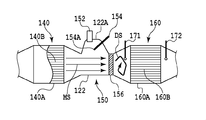
- the burner device 150 is configured such that a fuel supply valve 152 and a glow plug 154 are arranged with respect to a dome-shaped bulging portion 122A formed in a cylindrical exhaust pipe 122.
- the fuel supply valve 152 has one or a plurality of injection ports, and the injection ports are formed so as to supply fuel toward the center of the cylindrical exhaust pipe 122.
- the injection port of the fuel supply valve 152 in the present embodiment is formed so as to inject fuel in a conical shape.
- the fuel injected from fuel supply valve 152 is light oil that is the fuel of engine body 100.
- the fuel is not limited to this form, and a fuel different from the fuel of the engine body may be supplied.
- the glow plug 154 is disposed so as to heat or ignite the fuel supplied from the fuel supply valve 152.
- the glow plug 154 is formed such that the temperature of the heat generating portion 154A at the front end is increased, and downstream of the fuel supply valve 152 so that the fuel injected from the fuel supply valve 152 contacts the heat generating portion 154A at the front end. Placed in position.
- the glow plug 154 and the fuel supply valve 152 in the present embodiment are each formed in a rod shape, and are arranged so that the fuel spray from the fuel supply valve 152 appropriately reaches the tip heating portion 154A of the glow plug 154. Has been.
- the glow plug 154 is placed in the dome-shaped bulged portion 122A of the exhaust pipe 122 so that the tip heat generating portion 154A is located in a region deviated from the main flow of the exhaust gas indicated by the arrow MS in FIG. Inserted and installed.
- the glow plug 154 and the fuel supply valve 152 are not limited to a rod shape and may have any shape as long as the above-described requirements are satisfied.
- the glow plug 154 is connected to an in-vehicle DC power source via a booster circuit (not shown), and the heat generating portion 154A at the tip generates heat when energized. With the heat generated in the heat generating part 154A, the fuel supplied from the fuel supply valve 152 is ignited to generate a flame.
- a rectifying catalyst device 140 is disposed upstream of the burner device 150 described above.
- the outlet of the exhaust turbine 112b is disposed upstream of the rectifying catalyst device 140 as described above.
- a straight flow type base material 140B is supported on a cylindrical casing 140A, and a noble metal catalyst such as platinum Pt, rhodium Rd, or palladium Pd is supported on the base material. Is an supported oxidation catalyst.
- the rectifying catalyst device 140 used in the present invention a model in which the base material held in the cylindrical casing 140A described above is a metal base material, or a model in which the base material is a ceramic base material is used. May be used.
- a metal base material for example, a metal thin flat plate and a metal thin corrugated plate are laminated, and these are wound into a cylindrical shape and brazed.
- a noble metal catalyst such as platinum Pt, rhodium Rd, or palladium Pd may be supported on the catalyst carrier layer.
- the base material in the type that is a ceramic base material, the base material may be formed, for example, in a honeycomb structure from, for example, zeolite or cordierite, and the above-described noble metal catalyst may be supported thereon.
- Each of the rectifying catalyst devices 140 is a so-called straight flow type having a plurality of independent cells extending linearly from the upstream end to the downstream end.
- the base material supporting the catalyst may be either a straight flow type or a wall flow type as long as the flow at the outlet of the rectifying catalyst device 140 is rectified.
- a turbulent flow generator 156 is disposed in the exhaust gas passage downstream of the glow plug 154 and upstream of the oxidation catalyst 160.
- the oxidation catalyst 160 is an exhaust purification oxidation catalyst having a volume larger than that of the rectifying catalyst device 140.
- the oxidation catalyst 160 includes, for example, a base material 160B having a partition wall extending in the exhaust gas flow direction inside a cylindrical casing 160A.
- the base material 160B is formed in a honeycomb structure, for example.
- a coating layer made of, for example, a porous oxide powder is formed on the surface of the substrate 160B, and a noble metal catalyst such as platinum Pt is supported on the coating layer.
- the first temperature sensor 171 is disposed upstream of the oxidation catalyst 160 and the second temperature sensor 172 is disposed downstream of the oxidation catalyst 160.
- the exhaust gas discharged from the engine passes through the rectifying catalyst device 140 disposed on the upstream side of the burner device 150, and the fuel supply valve 152 and the glow plug 154 are exhausted. Flows into the burner device 150 including Since the rectifying catalyst device 140 is an oxidation catalyst, the rectifying catalyst device can be used even when the temperature of the exhaust gas is low, such as during cold start, or when the exhaust gas contains moisture. 140 removes such moisture and raises the temperature of the exhaust gas to some extent. At the same time, the exhaust gas flowing into the burner device 150 is rectified by the rectifying catalyst device 140.
- the exhaust gas passes through an exhaust treatment device typified by a burner device 150, a turbulent flow generator 156, and an oxidation catalyst 160 downstream of the rectifying catalyst device 140.
- the temperature Tc of the oxidation catalyst 160 is measured using the second temperature sensor 172. This is to determine whether or not temperature raising control for raising the temperature of the exhaust gas is required.
- this measured temperature Tc is lower than a predetermined value, it is considered that the temperature of the exhaust treatment device represented by the oxidation catalyst 160 is low and not activated, so that the exhaust gas is to be activated early.
- the temperature increase control is executed in the ECU 200. This temperature increase control may be terminated when the temperature Tc of the oxidation catalyst 160 reaches a predetermined value and the temperature increase control request is satisfied. Arbitrary conditions can be adopted for the end timing of the temperature increase control.
- step S702 it is determined whether or not the exhaust gas flow rate Ga exceeds a predetermined value G2. This is determined, for example, by determining the exhaust gas flow rate Ga from the amount of intake air based on the output value of the air flow meter 114, and whether the exhaust gas flow rate Ga is equal to or less than a predetermined value G2 suitable for ignition.
- the process proceeds to step S703, and fuel injection from the fuel supply valve 152 is started.
- step S704 fuel injection from the fuel supply valve 152 is not performed immediately (indicated in FIG. 7 as “stop fuel injection”).
- the fuel is ignited and a flame is generated by injecting fuel from the fuel supply valve 152 to the glow plug 154 heated to a high temperature. That is, the process shifts to the flame generation control state.
- the exhaust gas flowing into the burner device 150 is rectified by the rectifying catalyst device 140 as shown in FIG. 2 as the mainstream MS, so that the fuel spray injected from the fuel supply valve 152 is exhausted. It reaches the heat generating part 154A at the tip of the glow plug 154 stably without being affected by the gas flow. As a result, the ignitability or combustibility is improved.
- the fuel injection from the fuel supply valve 152 may be continuous or intermittent (pulsed).
- the temperature of the glow plug 154 may not increase immediately after energization. Therefore, the fuel injection from the fuel supply valve 152 is performed after the energization of the glow plug 154 is started. It may be performed after a predetermined time for raising the temperature of itself (this state is hereinafter referred to as a standby control state). However, even in this standby control state, the exhaust gas can be gently heated by the amount of heat generated by the glow plug 154, and the temperature of the oxidation catalyst 160 can be slightly increased.
- the flame generated by the burner device 150 is, together with the exhaust gas, downstream of the glow plug 154 and upstream of the oxidation catalyst 160 of the exhaust treatment device.
- a swirler or mixer is used. Through the turbulence generator 156 and downstream. Even if unburned HC or the like is generated in the burner device 150 without reaching complete combustion, the turbulent flow generator 156 generates a turbulent flow indicated by an arrow DS in FIG. It is diffused, mixed with oxygen and burned away. Therefore, the occurrence of smoke is suppressed.
- the temperature of the exhaust gas becomes high, and the high-temperature exhaust gas can be sent downstream.
- the oxidation catalyst 160 when the oxidation catalyst 160 is lower than the activation temperature, the temperature can be raised to the activation temperature in a short time, and when the oxidation catalyst 160 is higher than the activation temperature, the temperature is raised in a short time.
- the oxidation ability of the catalyst can be increased.
- the fuel is reformed by generating a flame, and a reducing agent such as HC or CO is generated.
- a reducing agent such as HC or CO is generated.
- This second embodiment is different from the first embodiment described above in the distance from the rectifying catalyst device 140 to the glow plug 154 as the ignition means, the distance from the glow plug 154 to the exhaust treatment device, or turbulent flow. Since the only difference is that the relationship with the distance from the generator 156 to the exhaust treatment device is determined, the same structural parts are denoted by the same reference numerals to avoid redundant description.
- the most upstream of the exhaust treatment device from the glow plug 154 is larger than the distance D from the outlet of the rectifying catalyst device 140 to the glow plug 154 (strictly speaking, the heat generating portion 154A at the tip).
- the exhaust passage is set so that the distance d1 to the oxidation catalyst 160 or the distance d2 from the turbulent flow generator 156 to the most upstream oxidation catalyst 160 of the exhaust treatment device is longer.
- the distance D from the rectifying catalyst device 140 to the glow plug 154 is short, attenuation of the rectifying effect by the rectifying catalyst device 140 is suppressed and its ignitability or combustibility is improved. Since the distance d1 from the plug 154 to the uppermost oxidation catalyst 160 of the exhaust treatment device or the distance d2 from the turbulent flow generator 156 to the uppermost oxidation catalyst 160 of the exhaust treatment device is longer, the diffusion of the combustion gas Performance is enhanced and the occurrence of smoke is suppressed.
- the turbulent flow generator 156 such as a swirler or a mixer is used as the turbulent flow generation structure in the first and second embodiments described above, whereas the exhaust pipe 122 that forms an exhaust passage is used. Since the only difference is that the bent pipe 122B is used, the same reference numerals are assigned to the same structural parts to avoid redundant description.
- the drift of the exhaust gas occurs in the bent pipe 122B of the exhaust pipe 122 that forms the exhaust passage, and thereby the turbulence in the exhaust gas flow occurs. Therefore, as in the case of the turbulent flow generator 156, unburned HC generated in the burner device 150 is conveniently diffused, mixed with oxygen, and removed by combustion, so that the generation of smoke is suppressed. .
- FIG. 6 shows a graph for explaining the relationship between the exhaust gas flow velocity (proportional to the flow rate) and the combustion performance.
- the horizontal axis is the exhaust gas flow velocity (flow rate), and the vertical axis is the combustion performance.
- the exhaust gas flow velocity V described here corresponds to the above-described exhaust gas flow rate Ga having a proportional relationship
- the second predetermined value V2 corresponds to the above-described predetermined value G2 of the exhaust gas flow rate.
- this decrease in combustion performance is detected by the first temperature sensor 171 as combustion performance detection means provided upstream of the oxidation catalyst 160, and the flow velocity V of the exhaust gas is determined. Control is performed so as to exceed the first predetermined value V1. Specifically, when the exhaust gas temperature downstream of the burner device 150 detected by the first temperature sensor 171 is equal to or lower than a predetermined value, it is determined that the combustion performance has deteriorated, and the flow rate Ga of the exhaust gas is set to a predetermined value G2.
- the increase control is performed while maintaining the following. That is, the exhaust gas flow rate Ga is controlled to increase so that the exhaust gas flow rate Ga exceeds a predetermined value G1 corresponding to the first predetermined value V1 of the exhaust gas flow velocity V, so that the combustion performance is improved.
- the increase control can be performed, for example, by adjusting the opening degree of the electric throttle valve 118 or by adjusting the EGR valve 126 arranged in the recirculation flow path of the engine body 100.
- the flow rate of the exhaust gas flowing into the burner device 150 can be increased by temporarily reducing the exhaust gas recirculation flow rate.
- This increase control is performed by controlling the above-described electric throttle valve 118 or EGR valve 126 by the ECU 200.
- the burner device 150 is provided with an air supply valve 155 connected to an air supply source as an air supply means.
- air is supplied from the air supply valve 155, assuming that the combustion performance is degraded. As a result, the oxygen concentration of the exhaust gas is increased.
- the heat generating portion 154A of the glow plug 154 that is, the ignition source
- the combustion speed in the vicinity is improved, and the turbulent flow DS of the exhaust gas is increased by improving the speed of combustion diffusion downstream thereof, thereby further improving the combustibility.
- the glow plug is adopted as the ignition means.
- the present invention is not limited to this form, and any ignition device capable of igniting the supplied fuel can be adopted.
- a spark plug or a ceramic heater may be employed.
- oxidation catalyst, DPF, and the NO X catalyst described by taking as an example but not limited to this embodiment the present invention to any device for purifying exhaust can do.
- a diesel engine is taken as an example of the internal combustion engine, but the present invention can also be applied to a spark ignition internal combustion engine (gasoline engine) equipped with an optional burner device.
- a spark ignition internal combustion engine gasoline engine
Abstract
An internal combustion engine equipped with a burner apparatus is provided with: an exhaust processing apparatus disposed in an exhaust gas passageway and configured to purify exhaust gas; a burner apparatus disposed upstream of the exhaust processing apparatus in the exhaust gas passageway and including a fuel supply valve for supplying fuel to an exhaust gas flow, and an igniting apparatus disposed between the exhaust processing apparatus and the fuel supply valve and configured to ignite the fuel supplied from the fuel supply valve; and a rectification catalyst apparatus disposed upstream of the burner apparatus in the exhaust gas passageway. This configuration enables sprayed fuel to be ignited or combusted more stably and reliably, so that preferable operating conditions for the exhaust processing apparatus can be achieved in a short time.
Description
本発明は、内燃機関、特に排気ガス温度上昇用のバーナー装置を備える内燃機関に関する。
The present invention relates to an internal combustion engine, and more particularly to an internal combustion engine provided with a burner device for increasing exhaust gas temperature.
ディーゼルエンジンやガソリンエンジンなどの内燃機関では、機関本体で燃料が燃焼され、例えば、一酸化炭素(CO)、未燃炭化水素(HC)、窒素酸化物(NOX)またはパティキュレート(PM)などを含む排気ガスが排出される。このような排気ガスを浄化するために、一酸化炭素、未燃炭化水素などを酸化するための酸化触媒、窒素酸化物を除去するためのNOX触媒、パティキュレートを除去するためのパティキュレートフィルタ等を含む排気処理装置が内燃機関に設けられている。
In an internal combustion engine such as a diesel engine or a gasoline engine, fuel is combusted in the engine body. For example, carbon monoxide (CO), unburned hydrocarbon (HC), nitrogen oxide (NO x ), or particulate (PM) Exhaust gas containing is discharged. To purify such exhaust gases, carbon monoxide, unburned hydrocarbons oxidation catalyst for oxidizing the like, NO X catalyst for removing nitrogen oxides, particulate filter for removing particulates An exhaust treatment device including the above is provided in the internal combustion engine.
ところで、これらの排気処理装置は、それぞれの機能を発揮するためには、温度や還元剤の量などにおいて好適な運転条件を必要とする。内燃機関から排出される排気ガスの浄化が必要なときには、この運転条件を短時間に達成できることが好ましい。このために、内燃機関の排気ガス通路において、排気処理装置の上流側にバーナー装置を設け、該バーナー装置で生成された加熱ガスを利用して排気ガス温度を上昇させることによって、排気処理装置を処理可能な活性状態にする技術が知られている(例えば、特許文献1参照)。
By the way, these exhaust treatment devices require suitable operating conditions in terms of temperature, amount of reducing agent, and the like in order to perform their respective functions. When it is necessary to purify the exhaust gas discharged from the internal combustion engine, it is preferable that this operating condition can be achieved in a short time. For this purpose, in the exhaust gas passage of the internal combustion engine, a burner device is provided on the upstream side of the exhaust treatment device, and the exhaust gas temperature is increased by using the heated gas generated by the burner device. A technique for making a processable active state is known (see, for example, Patent Document 1).
この特許文献1に記載のバーナー装置は、排気処理装置よりも上流側に配置され、機関の排気ガス通路より小さな断面積を有して、排気ガスの一部が内部を流通する小型酸化触媒と、排気ガス通路内の該小型酸化触媒に向けて燃料を供給する燃料供給手段と、供給された燃料を着火し燃焼させる着火手段とを備えている。
The burner device disclosed in Patent Document 1 is disposed on the upstream side of the exhaust treatment device, has a smaller cross-sectional area than the exhaust gas passage of the engine, and a small oxidation catalyst in which a part of the exhaust gas flows. The fuel supply means supplies fuel toward the small oxidation catalyst in the exhaust gas passage, and the ignition means ignites and burns the supplied fuel.
ところで、上記特許文献1に記載のバーナー装置を備える内燃機関においては、燃料供給弁から供給された燃料を着火し燃焼させるためのグロープラグを有している。そして、かかる燃料供給弁が小型酸化触媒に向けて燃料を供給又は停止し、燃料供給弁と小型酸化触媒との間に配置されたグロープラグが周りを加熱し又は停止する旨、記載されている。より詳しくは、着火が可能な運転領域において、着火手段による加熱を行って供給された燃料を着火させる第1の制御状態、又は燃料の供給を行うが着火手段による加熱が停止している第3の制御状態に制御する一方、着火が不可能な運転領域においては、燃料の供給を行い着火手段による加熱を行うが燃料は着火しない第2の制御状態、又は上記の第3の制御状態に制御することが開示されている。
Incidentally, an internal combustion engine provided with the burner device described in Patent Document 1 has a glow plug for igniting and burning the fuel supplied from the fuel supply valve. And it is described that such a fuel supply valve supplies or stops fuel toward the small oxidation catalyst, and a glow plug disposed between the fuel supply valve and the small oxidation catalyst heats or stops the surroundings. . More specifically, in the operation region where ignition is possible, the first control state in which the fuel supplied by igniting by the ignition means is heated, or the third in which the fuel is supplied but the heating by the ignition means is stopped. On the other hand, in the operation region where ignition is impossible, control is performed to the second control state in which fuel is supplied and heating is performed by the ignition means but the fuel is not ignited, or the third control state described above. Is disclosed.
このように、上記特許文献1に記載のバーナー装置を備える内燃機関においては、着火が可能な運転領域において、第1の制御状態または第3の制御状態に制御して、着火が不可能な運転領域において、第2の制御状態または第3の制御状態に制御することにより、排気ガスの状態や排気処理装置の状態に応じて、第1の制御状態、第2の制御状態および第3の制御状態で運転を行うことにより、排気処理装置の好適な運転条件を短時間で達成することができるとしている。
As described above, in the internal combustion engine including the burner device described in Patent Document 1, in the operation region where ignition is possible, the operation is controlled so as to be in the first control state or the third control state and cannot be ignited. In the region, by controlling to the second control state or the third control state, the first control state, the second control state, and the third control are performed according to the state of the exhaust gas or the state of the exhaust treatment device. By operating in the state, it is said that a suitable operating condition of the exhaust treatment device can be achieved in a short time.
しかしながら、上述のようなバーナー装置においては、喩え着火が可能な運転領域においても、排気ガス流れの影響を受けて着火が確実に行われなくなる場合があることが判明した。すなわち、燃料は燃料供給弁からグロープラグに向けて噴射供給されるが、しかし、この噴射された燃料噴霧は、排気ガス流れの影響を受けて流されるために、グロープラグへの到達挙動が変動し、その着火性ないしは燃焼性が変動するからである。例えば、排気ガスの流速が所定値を超えて高い場合における排気ガス流れの乱れ、バーナー装置の上流にターボチャージャの排気タービンが存する場合などにおける排気ガスの旋回流れ、又はバーナー装置の上流に排気管の曲がり部が存する場合などにおける排気ガスの偏流によって、燃料噴霧の到達挙動の変動が顕著となり、着火性ないしは燃焼性が低下して安定した燃焼を維持することが困難となるのである。
However, it has been found that, in the burner apparatus as described above, even in an operation region where ignition is possible, ignition may not be performed reliably due to the influence of the exhaust gas flow. That is, the fuel is injected and supplied from the fuel supply valve toward the glow plug. However, since the injected fuel spray is flowed by the influence of the exhaust gas flow, the behavior of reaching the glow plug varies. This is because its ignitability or flammability varies. For example, the exhaust gas flow is disturbed when the exhaust gas flow rate is higher than a predetermined value, the exhaust gas swirl flow when the turbocharger exhaust turbine exists upstream of the burner device, or the exhaust pipe upstream of the burner device Due to the drift of the exhaust gas when there is a bent portion, the arrival behavior of the fuel spray becomes noticeable and the ignitability or combustibility is lowered, making it difficult to maintain stable combustion.
また、排気ガスの温度が低い場合(例えば、150℃以下)や排気ガスが水分を含むような場合にも着火が確実に行われず、安定した燃焼を維持できなくなる恐れがあることも判明した。
Also, it has been found that even when the temperature of the exhaust gas is low (for example, 150 ° C. or lower) or when the exhaust gas contains moisture, ignition is not reliably performed and stable combustion may not be maintained.
本発明は、このような問題を解消し、燃料噴霧の着火ないしは燃焼をより安定して確実に行い排気処理装置の好適な運転条件を短時間で達成できるバーナー装置を備える内燃機関を提供することを目的とする。
The present invention provides an internal combustion engine provided with a burner device that solves such problems and can stably and reliably ignite or burn fuel spray and achieve suitable operating conditions of an exhaust treatment device in a short time. With the goal.
上記目的を達成する本発明に係るバーナー装置を備える内燃機関の一形態は、排気ガス通路内に配置され、排気ガスの浄化を行う排気処理装置と、排気ガス通路内において、該排気処理装置よりも上流側に配置されたバーナー装置であって、排気ガス流に燃料を供給する燃料供給手段と、排気処理装置と燃料供給手段との間に配置され、燃料供給手段から供給された燃料を着火させる着火手段とを含むバーナー装置と、排気ガス通路内において、該バーナー装置よりも上流側に配置された整流用触媒装置と、を備えることを特徴とする。
An embodiment of an internal combustion engine including a burner device according to the present invention that achieves the above object is provided in an exhaust gas passage, and an exhaust treatment device that purifies exhaust gas, and in the exhaust gas passage, Is also a burner device arranged upstream, a fuel supply means for supplying fuel to the exhaust gas flow, and arranged between the exhaust treatment device and the fuel supply means for igniting the fuel supplied from the fuel supply means And a rectifying catalyst device disposed upstream of the burner device in the exhaust gas passage.
この一形態によれば、燃料供給手段と着火手段とを含むバーナー装置に対して、該バーナー装置よりも上流側に配置された整流用触媒装置を通して、機関から排出された排気ガスが流入することになる。この流入する排気ガスは整流用触媒装置によって整流されているので、燃料供給手段から噴射された燃料噴霧は排気ガスの流れの影響をそれほど受けず、着火手段に安定して到達する。この結果、その着火性ないしは燃焼性が向上する。また、排気ガスの温度が低い場合や排気ガスが水分を含むような場合であっても、整流用触媒装置によってかかる水分が除去されることから、排気ガスの温度が上昇され、着火性ないしは燃焼性をより安定して向上させることができる。このために、整流用触媒装置は酸化触媒であることが好ましい。また、その触媒を担持する基材は、整流用触媒装置の出口での流れが整流されている限り、ストレートフロー型又はウォールフロー型のいずれであってもよい。
According to this aspect, the exhaust gas discharged from the engine flows into the burner device including the fuel supply means and the ignition means through the rectifying catalyst device disposed upstream of the burner device. become. Since the inflowing exhaust gas is rectified by the rectifying catalyst device, the fuel spray injected from the fuel supply means is not significantly affected by the flow of the exhaust gas and reaches the ignition means stably. As a result, the ignitability or combustibility is improved. Further, even when the temperature of the exhaust gas is low or when the exhaust gas contains moisture, the moisture is removed by the rectifying catalyst device, so that the temperature of the exhaust gas is raised and the ignitability or combustion is increased. The property can be improved more stably. For this reason, the rectifying catalyst device is preferably an oxidation catalyst. Further, the base material supporting the catalyst may be either a straight flow type or a wall flow type as long as the flow at the outlet of the rectifying catalyst device is rectified.
ここで、上記一形態は、排気ガス通路内において、着火手段の下流であって、排気処理装置よりも上流側に配置され、排気ガスの乱れを生じさせる乱流生成構造をさらに備えることが好ましい。この形態によれば、着火手段の下流において着火された燃焼ガスは乱流生成構造によって拡散されるので、スモークの発生を抑制することができる。なお、この乱流生成構造としては、スワラーやミキサーのような乱流生成器、又は排気管そのものの曲がり構造を挙げることができる。
Here, it is preferable that the one aspect further includes a turbulent flow generation structure that is disposed downstream of the ignition means in the exhaust gas passage and upstream of the exhaust treatment device, and causes turbulence of the exhaust gas. . According to this aspect, since the combustion gas ignited downstream of the ignition means is diffused by the turbulent flow generation structure, the generation of smoke can be suppressed. Examples of the turbulent flow generating structure include a turbulent flow generator such as a swirler and a mixer, or a bent structure of the exhaust pipe itself.
また、上記一形態において、整流用触媒装置から着火手段までの距離よりも、着火手段から排気処理装置までの距離、又は乱流生成構造から排気処理装置までの距離の方が長いことが好ましい。この構成によれば、整流用触媒装置から着火手段までの距離が短いので、整流用触媒装置による整流効果の減衰が抑制されその着火性ないしは燃焼性が向上するのに対し、着火手段又は乱流生成構造から排気処理装置までの距離の方が長いことから、燃焼ガスの拡散性が高められ、スモークの発生が抑制される。
In the above embodiment, it is preferable that the distance from the ignition means to the exhaust treatment device or the distance from the turbulent flow generation structure to the exhaust treatment device is longer than the distance from the rectifying catalyst device to the ignition means. According to this configuration, since the distance from the rectifying catalyst device to the ignition means is short, the attenuation of the rectifying effect by the rectifying catalyst device is suppressed and its ignitability or flammability is improved. Since the distance from the generation structure to the exhaust treatment device is longer, the diffusibility of the combustion gas is enhanced and the generation of smoke is suppressed.
ここで、上記一形態は燃料供給手段及び着火手段の制御を行う制御手段をさらに備え、該制御手段は、排気ガス通路内における排気ガスの流速が所定値を超えるときは、供給燃料が燃焼しないように、燃料供給手段及び着火手段を制御するようにしてもよい。この構成によれば、排気ガス通路内における排気ガスの流速が所定値を超えない低流速条件でのみ供給燃料が燃焼するように、燃料供給手段及び着火手段が制御されるので、安定した着火性及び燃焼性の下に燃焼を行わせることができる。
Here, the one aspect further includes control means for controlling the fuel supply means and the ignition means, and the control means does not burn the supplied fuel when the flow rate of the exhaust gas in the exhaust gas passage exceeds a predetermined value. As described above, the fuel supply means and the ignition means may be controlled. According to this configuration, the fuel supply means and the ignition means are controlled so that the supplied fuel burns only at a low flow rate condition in which the flow rate of the exhaust gas in the exhaust gas passage does not exceed a predetermined value. And combustion can be performed under flammability.
また、上記一形態は、排気ガス通路内において、着火手段の下流であって、排気処理装置よりも上流側に配置され、着火された燃料の燃焼性能を検出する燃焼性能検出手段をさらに備え、該燃焼性能検出手段により検出された燃焼性能が所定値以下のときに、排気ガスの量を所定量以下に維持しつつ増量制御する制御手段、又は排気ガスの酸素濃度又は酸素量を増加制御する制御手段を、さらに備えてもよい。この構成によれば、燃焼性能が所定値以下のときに、排気ガスの量を所定量以下に維持しつつ増量制御することによって、着火手段の下流における燃焼ガスの乱流が増大されて、燃焼性が向上される。または、燃焼性能が所定値以下のときに、排気ガスの酸素濃度又は酸素量を増加制御することによって、着火手段の下流における燃焼ガスの燃焼速度が高められ乱流が増大されて、燃焼性がより向上される。
Further, the one aspect further includes a combustion performance detection means that is disposed downstream of the ignition means in the exhaust gas passage and upstream of the exhaust treatment device, and detects the combustion performance of the ignited fuel, When the combustion performance detected by the combustion performance detecting means is below a predetermined value, the control means for controlling the increase while maintaining the amount of exhaust gas below the predetermined amount, or increasing the oxygen concentration or oxygen amount of the exhaust gas. Control means may be further provided. According to this configuration, when the combustion performance is less than or equal to the predetermined value, the turbulent flow of the combustion gas downstream of the ignition means is increased by controlling the increase while maintaining the amount of the exhaust gas below the predetermined amount, and the combustion Is improved. Alternatively, when the combustion performance is below a predetermined value, by increasing the oxygen concentration or oxygen amount of the exhaust gas, the combustion speed of the combustion gas downstream from the ignition means is increased, turbulence is increased, and the combustibility is increased. More improved.
なお、上記発明において、排気処理装置は、酸化触媒、NOX触媒およびパティキュレートフィルタのうちの、少なくとも1つを含んでもよい。
In the above invention, the exhaust treatment device, the oxidation catalyst, of of the NO X catalyst and the particulate filter may comprise at least one.
本発明によれば、燃料噴霧の着火ないしは燃焼をより安定して確実に行い、排気処理装置の好適な運転状態を短時間で達成できるバーナー装置を備える内燃機関を提供することができる。
According to the present invention, it is possible to provide an internal combustion engine including a burner device that can stably and surely ignite or burn fuel spray and achieve a suitable operating state of the exhaust treatment device in a short time.
以下、添付図面を参照して、本発明に係るバーナー装置を備える内燃機関の実施の形態について説明する。
Hereinafter, an embodiment of an internal combustion engine provided with a burner device according to the present invention will be described with reference to the accompanying drawings.
図1は、本発明に係るバーナー装置を備える内燃機関の全体を示す模式図である。以下においては、圧縮着火式の内燃機関であるディーゼルエンジンを例に取り上げて説明する。内燃機関は、エンジン本体100を備え、エンジン本体100は、各気筒の燃焼室102と、各燃焼室102内に夫々燃料を噴射するための電子制御式の燃料噴射弁104と、吸気マニホールド106と、排気マニホールド108とを含んでいる。
FIG. 1 is a schematic view showing an entire internal combustion engine equipped with a burner device according to the present invention. In the following, a diesel engine which is a compression ignition type internal combustion engine will be described as an example. The internal combustion engine includes an engine main body 100. The engine main body 100 includes a combustion chamber 102 for each cylinder, an electronically controlled fuel injection valve 104 for injecting fuel into each combustion chamber 102, an intake manifold 106, and the like. , And an exhaust manifold 108.
吸気マニホールド106は、吸気ダクト110を介してターボチャージャ112のコンプレッサ112aの出口に連結されている。コンプレッサ112aの入口は、エアフローメータ114を介してエアクリーナ116に連結されている。このエアフローメータ114により、エンジン本体100に単位時間当たりに流入する吸入空気量(ないしは、排気ガス流量)が検出される。さらに、吸気ダクト110内には電動モータなどにより駆動される電制スロットルバルブ118が配置され、更に吸気ダクト110の周りには吸気ダクト110内を流れる吸入空気を冷却するためのインタークーラー120が配置されている。なお、図1に示される実施形態では機関冷却水がインタークーラー120内に導かれ、機関冷却水によって吸入空気が冷却される。
The intake manifold 106 is connected to the outlet of the compressor 112a of the turbocharger 112 through the intake duct 110. An inlet of the compressor 112 a is connected to an air cleaner 116 via an air flow meter 114. The air flow meter 114 detects the amount of intake air (or exhaust gas flow rate) flowing into the engine body 100 per unit time. Further, an electric throttle valve 118 driven by an electric motor or the like is disposed in the intake duct 110, and an intercooler 120 for cooling the intake air flowing in the intake duct 110 is disposed around the intake duct 110. ing. In the embodiment shown in FIG. 1, the engine cooling water is guided into the intercooler 120, and the intake air is cooled by the engine cooling water.
一方、排気マニホールド108は、ターボチャージャ112の排気タービン112bの入口に連結されている。排気タービン112bの出口は、排気管122に接続されている。また、排気マニホールド108と吸気マニホールド106との間には、排気ガス再循環(EGR)を行うためのEGR通路124が配置されている。EGR通路124内には電子制御式のEGRバルブ126が配置されている。また、EGR通路124の周りにはEGR通路124内を流れるEGRガスを冷却するためのEGRクーラー128が配置されている。図1に示された実施形態では機関冷却水がEGRクーラー128内に導かれ、機関冷却水によってEGRガスが冷却される。
On the other hand, the exhaust manifold 108 is connected to the inlet of the exhaust turbine 112b of the turbocharger 112. The outlet of the exhaust turbine 112 b is connected to the exhaust pipe 122. Further, an EGR passage 124 for performing exhaust gas recirculation (EGR) is disposed between the exhaust manifold 108 and the intake manifold 106. An electronically controlled EGR valve 126 is disposed in the EGR passage 124. Further, an EGR cooler 128 for cooling the EGR gas flowing in the EGR passage 124 is disposed around the EGR passage 124. In the embodiment shown in FIG. 1, the engine cooling water is guided into the EGR cooler 128, and the EGR gas is cooled by the engine cooling water.
さらに、それぞれの燃料噴射弁104は、燃料供給管130を介してコモンレール132に連結されている。このコモンレール132は、電子制御式の吐出量可変な燃料ポンプ134を介して燃料タンク136に連結されている。燃料タンク136内に貯蔵されている燃料は、燃料ポンプ134によってコモンレール132内に供給される。コモンレール132内に供給された燃料は、それぞれの燃料供給管130を介して燃料噴射弁104に供給される。
Furthermore, each fuel injection valve 104 is connected to a common rail 132 via a fuel supply pipe 130. The common rail 132 is connected to the fuel tank 136 via an electronically controlled variable discharge amount fuel pump 134. The fuel stored in the fuel tank 136 is supplied into the common rail 132 by the fuel pump 134. The fuel supplied into the common rail 132 is supplied to the fuel injection valve 104 through each fuel supply pipe 130.
一方、排気タービン112bの出口よりも下流の排気管122においては、排気タービン112bの出口の直ぐ下流の排気ガス通路内に、後で詳述する整流用触媒装置140が配置され、その下流に排気ガス流に燃料を供給する燃料供給手段としての燃料供給弁152と燃料供給弁152から供給された燃料を着火させる着火手段としてのグロープラグ154とを含むバーナー装置150が配置されている。そして、本実施形態では、バーナー装置150はグロープラグ154よりも下流に後で詳述する乱流発生器156を備えている。
On the other hand, in the exhaust pipe 122 downstream of the outlet of the exhaust turbine 112b, a rectifying catalyst device 140, which will be described in detail later, is disposed in the exhaust gas passage immediately downstream of the outlet of the exhaust turbine 112b. A burner device 150 including a fuel supply valve 152 as a fuel supply means for supplying fuel to the gas flow and a glow plug 154 as an ignition means for igniting the fuel supplied from the fuel supply valve 152 is disposed. And in this embodiment, the burner apparatus 150 is provided with the turbulent flow generator 156 explained in full detail downstream from the glow plug 154 later.
さらに、バーナー装置150の下流は、排気ガス通路内に配置され排気ガスの浄化を行う排気浄化触媒としての酸化触媒160に連結されている。酸化触媒160の下流の排気ガス通路内には、排気ガス中のパティキュレートを捕集するためのパティキュレートフィルタ(以下、DPFと称す)162が配置されている。また、このDPF162の下流の排気ガス通路内には、図1に示される実施形態では、NOx触媒として選択還元型NOX触媒(SCR: Selective Catalytic Reduction)164が配置されると共に、その上流に後で詳述する尿素添加弁166が設けられている。選択還元型NOX触媒164は、ゼオライト又はアルミナなどの基材表面にPtなどの貴金属が担持されたものや、その基材表面にCuなどの遷移金属をイオン交換して担持させたもの、その基材表面にチタニヤ/バナジウム触媒(V2O5/WO3/TiO2)を担持させたものなどを例示することができる。選択還元型NOX触媒164は、その触媒温度が活性温度域にあり、且つ、還元剤としての尿素が添加されているときに、NOxを還元浄化する。尿素が尿素添加弁166から噴射されて選択還元型NOX触媒164に添加されると、触媒上でアンモニアが生成され、このアンモニアがNOxと反応してNOxが還元される。これらの酸化触媒160、DPF162および選択還元型NOX触媒164は、排気を浄化する機能を有する排気処理装置を構成している。
Further, the downstream of the burner device 150 is connected to an oxidation catalyst 160 as an exhaust purification catalyst that is disposed in the exhaust gas passage and purifies the exhaust gas. In the exhaust gas passage downstream of the oxidation catalyst 160, a particulate filter (hereinafter referred to as DPF) 162 for collecting particulates in the exhaust gas is disposed. Further, in the downstream of the exhaust gas passage of the DPF162, in the embodiment shown in FIG. 1, chosen as the NOx catalyst reduction type NO X catalyst (SCR: Selective Catalytic Reduction) with 164 it is arranged, after the upstream A urea addition valve 166 described in detail in FIG. The selective reduction type NO X catalyst 164 has a surface of a base material such as zeolite or alumina supported by a noble metal such as Pt, or a surface of the base material supported by ion exchange of a transition metal such as Cu, Examples thereof include those in which a titania / vanadium catalyst (V 2 O 5 / WO 3 / TiO 2 ) is supported on the substrate surface. Selective reduction type NO X catalyst 164, the catalyst temperature is in the active temperature region, and, when the urea as a reducing agent is added to reduce and purify NOx. When urea is added to the selective reduction type NO X catalyst 164 is injected through the urea addition valve 166, ammonia is generated on the catalyst, NOx is reduced by reacting the ammonia with NOx. These oxidation catalysts 160, DPF162 and selective reduction type NO X catalyst 164 constitute an exhaust treatment apparatus having a function for purifying exhaust.
ここで、酸化触媒160は、HC,COなどの未燃成分をO2と反応させて、CO,CO2,H2O等とする。触媒物質としては、例えばPt/CeO2、Mn/CeO2、Fe/CeO2、Ni/CeO2、Cu/CeO2等を用いることができる。なお、NOx触媒としては上述の選択還元型NOX触媒164に替えて、吸蔵還元型NOx触媒(NSR: NOx Storage Reduction)を用いてもよい。この吸蔵還元型NOx触媒は、流入する排気ガスの酸素濃度が高いときは排気ガス中のNOxを吸蔵し、流入する排気ガスの酸素濃度が低下し且つ還元成分(例えば、燃料等)が存在するときは吸蔵していたNOxを放出して還元する機能を有する。
Here, the oxidation catalyst 160 reacts unburned components such as HC and CO with O 2 to make CO, CO 2 , H 2 O, and the like. As the catalyst material, for example, Pt / CeO 2 , Mn / CeO 2 , Fe / CeO 2 , Ni / CeO 2 , Cu / CeO 2 or the like can be used. As the NOx catalyst in place of the selective reduction type NO X catalyst 164 described above, the NOx storage reduction catalyst (NSR: NOx Storage Reduction) may be used. This NOx storage reduction catalyst stores NOx in the exhaust gas when the oxygen concentration of the inflowing exhaust gas is high, the oxygen concentration of the inflowing exhaust gas is reduced, and there are reducing components (for example, fuel). Sometimes it has the function of releasing and reducing the stored NOx.
なお、DPF162は、貴金属からなる触媒が担持され、捕集した微粒子を連続的に酸化燃焼により除去する連続再生式のものであってもよい。また、DPF162は、少なくとも酸化触媒160の下流側であって、且つNOx触媒の上流側若しくは下流側に配置されてもよい。
The DPF 162 may be a continuous regeneration type in which a catalyst made of a noble metal is supported and the collected fine particles are continuously removed by oxidative combustion. Further, the DPF 162 may be disposed at least downstream of the oxidation catalyst 160 and upstream or downstream of the NOx catalyst.
さらに、乱流発生器156の下流(ないしは、酸化触媒160の上流)にはバーナー装置150での燃焼性能を判定するために、そこの温度を検出する第1の温度センサ171が配置されている。また、酸化触媒160の下流には、排気処理装置の活性要求度を判定するために、酸化触媒160の温度を検出する第2の温度センサ172が配置されている。なお、DPF162には、DPF162の前後差圧を検出するための不図示の差圧センサが取付けられている。
Further, in order to determine the combustion performance in the burner device 150 downstream of the turbulent flow generator 156 (or upstream of the oxidation catalyst 160), a first temperature sensor 171 for detecting the temperature there is disposed. . Further, a second temperature sensor 172 that detects the temperature of the oxidation catalyst 160 is disposed downstream of the oxidation catalyst 160 in order to determine the degree of activity requirement of the exhaust treatment device. Note that a differential pressure sensor (not shown) for detecting the differential pressure across the DPF 162 is attached to the DPF 162.
さらに、図1に示すように、エンジン本体100の運転状態や運転者の要求等に応じて各種デバイスを制御するための電子制御ユニット(以下、ECUという)200が併設されている。このECU200は、エンジン制御に係る各種演算処理を実行するCPU、その制御に必要なプログラムやデータを記憶するROM、CPUの演算結果等を一時記憶するRAM、外部との間で信号を入出力するための入出力ポート等を備えるマイクロコンピュータを主体として構成されている。
Furthermore, as shown in FIG. 1, an electronic control unit (hereinafter referred to as ECU) 200 for controlling various devices in accordance with the operating state of the engine body 100, the driver's request, and the like is also provided. This ECU 200 inputs and outputs signals to and from the CPU that executes various arithmetic processes related to engine control, a ROM that stores programs and data necessary for the control, a RAM that temporarily stores CPU calculation results, and the like. It is mainly composed of a microcomputer provided with an input / output port for the purpose.
ECU200には、上述した第1及び第2の温度センサ171及び172、差圧センサ及びエアフローメータ114の他、エンジン本体100のクランク角を検出するクランク角センサ、アクセルペダルの踏み込み量に応じた電気信号を出力するアクセル開度センサを含む各種センサ類が、電気配線を介して接続され、これらの出力信号が対応するAD変換器を介してECU200の入力ポートに入力される。
In addition to the first and second temperature sensors 171 and 172, the differential pressure sensor and the air flow meter 114 described above, the ECU 200 includes a crank angle sensor for detecting the crank angle of the engine body 100, and an electric power corresponding to the amount of depression of the accelerator pedal. Various sensors including an accelerator opening sensor that outputs a signal are connected via electric wiring, and these output signals are input to an input port of the ECU 200 via a corresponding AD converter.
一方、出力ポートは、対応する駆動回路を介して燃料噴射弁104、電制スロットルバルブ118の駆動用電動モータ、EGRバルブ126および燃料ポンプ134などに接続されている。さらに、出力ポートは、対応する駆動回路を介して燃料供給弁152およびグロープラグ154及び尿素添加弁166を含む各種デバイスが電気配線を介して接続され、これらがECU200によって制御される。ECU200は、エアフローメータ114の出力値に基づいて吸入空気量(すなわち、排気ガス量)Gaを検出し、クランク角センサの出力値に基づいて機関回転数を検出し、アクセル開度センサの出力値に基づいてエンジン本体100への要求負荷を検出することができる。
On the other hand, the output port is connected to the fuel injection valve 104, the electric motor for driving the electric throttle valve 118, the EGR valve 126, the fuel pump 134, and the like through corresponding drive circuits. Furthermore, the output port is connected to various devices including a fuel supply valve 152, a glow plug 154, and a urea addition valve 166 via corresponding drive circuits, and these are controlled by the ECU 200. The ECU 200 detects the intake air amount (that is, the exhaust gas amount) Ga based on the output value of the air flow meter 114, detects the engine speed based on the output value of the crank angle sensor, and outputs the output value of the accelerator opening sensor. The required load on the engine main body 100 can be detected based on the above.
本実施形態では、バーナー装置150を用いた排気ガスの昇温制御を実施する際に、ECU200が燃料供給弁152およびグロープラグ154を作動させる。すなわち、ECU200は、燃料供給弁152を適宜開弁駆動(オン)し、燃料供給弁152から適宜燃料を噴射させる。またECU200は、グロープラグ154を適宜通電して十分な高温とする。
In the present embodiment, the ECU 200 operates the fuel supply valve 152 and the glow plug 154 when the exhaust gas temperature raising control using the burner device 150 is performed. That is, the ECU 200 appropriately opens (turns on) the fuel supply valve 152 to inject fuel from the fuel supply valve 152. In addition, the ECU 200 energizes the glow plug 154 as appropriate so that the temperature is sufficiently high.
図2を参照して、バーナー装置150の近傍構成の第1の実施形態を説明する。この第1の実施形態においては、バーナー装置150は筒状の排気管122に形成されているドーム状の膨出部122Aに対して、燃料供給弁152及びグロープラグ154が配置されて構成されている。燃料供給弁152は単数又は複数の噴射口を有し、噴射口は筒状の排気管122の中心部に向けて燃料を供給するように形成されている。本実施の形態における燃料供給弁152の噴射口は、燃料を円錐状に噴射する様に形成されている。そして、本実施の形態において、燃料供給弁152から噴射される燃料は、エンジン本体100の燃料である軽油である。但し、燃料については、この形態に限られず機関本体の燃料とは異なる燃料が供給されても構わない。
Referring to FIG. 2, a first embodiment of the configuration near the burner device 150 will be described. In the first embodiment, the burner device 150 is configured such that a fuel supply valve 152 and a glow plug 154 are arranged with respect to a dome-shaped bulging portion 122A formed in a cylindrical exhaust pipe 122. Yes. The fuel supply valve 152 has one or a plurality of injection ports, and the injection ports are formed so as to supply fuel toward the center of the cylindrical exhaust pipe 122. The injection port of the fuel supply valve 152 in the present embodiment is formed so as to inject fuel in a conical shape. In the present embodiment, the fuel injected from fuel supply valve 152 is light oil that is the fuel of engine body 100. However, the fuel is not limited to this form, and a fuel different from the fuel of the engine body may be supplied.
グロープラグ154は、燃料供給弁152から供給される燃料を加熱ないしは着火するように配置されている。グロープラグ154は、先端の発熱部154Aの温度が上昇するように形成されており、この先端の発熱部154Aに燃料供給弁152から噴射される燃料が衝接するように、燃料供給弁152より下流位置に配置されている。本実施の形態におけるグロープラグ154および燃料供給弁152は、それぞれが棒状に形成されており、燃料供給弁152からの燃料噴霧がグロープラグ154の先端発熱部154Aに適切に到達するように、配置されている。そして、グロープラグ154は、その先端発熱部154Aが、図1に矢印MSで示した排気ガスの主流から外れた領域に位置されるように、排気管122のドーム状の膨出部122A内に挿入されて取付けられている。なお、グロープラグ154および燃料供給弁152は、上述の要件を満たす限り、棒状に限らず任意の形状のものが用いられても構わない。グロープラグ154は、図示しない昇圧回路を経て車載の直流電源に接続されており、通電された際に先端の発熱部154Aが発熱する。発熱部154Aで発生した熱により、燃料供給弁152から供給された燃料を着火させて火炎を生じさせる。
The glow plug 154 is disposed so as to heat or ignite the fuel supplied from the fuel supply valve 152. The glow plug 154 is formed such that the temperature of the heat generating portion 154A at the front end is increased, and downstream of the fuel supply valve 152 so that the fuel injected from the fuel supply valve 152 contacts the heat generating portion 154A at the front end. Placed in position. The glow plug 154 and the fuel supply valve 152 in the present embodiment are each formed in a rod shape, and are arranged so that the fuel spray from the fuel supply valve 152 appropriately reaches the tip heating portion 154A of the glow plug 154. Has been. The glow plug 154 is placed in the dome-shaped bulged portion 122A of the exhaust pipe 122 so that the tip heat generating portion 154A is located in a region deviated from the main flow of the exhaust gas indicated by the arrow MS in FIG. Inserted and installed. Note that the glow plug 154 and the fuel supply valve 152 are not limited to a rod shape and may have any shape as long as the above-described requirements are satisfied. The glow plug 154 is connected to an in-vehicle DC power source via a booster circuit (not shown), and the heat generating portion 154A at the tip generates heat when energized. With the heat generated in the heat generating part 154A, the fuel supplied from the fuel supply valve 152 is ignited to generate a flame.
そして、上述のバーナー装置150の上流には、整流用触媒装置140が配置されている。なお、この整流用触媒装置140の上流には、図2には示されないが、排気タービン112bの出口が配置されていること前述の通りである。第1の実施形態で用いられている整流用触媒装置140は、円筒状ケーシング140Aにストレートフロー型の基材140Bが支持され、この基材に白金Pt、ロジウムRd、パラジウムPdのような貴金属触媒が担持されている酸化触媒である。
Further, a rectifying catalyst device 140 is disposed upstream of the burner device 150 described above. Although not shown in FIG. 2, the outlet of the exhaust turbine 112b is disposed upstream of the rectifying catalyst device 140 as described above. In the rectifying catalyst device 140 used in the first embodiment, a straight flow type base material 140B is supported on a cylindrical casing 140A, and a noble metal catalyst such as platinum Pt, rhodium Rd, or palladium Pd is supported on the base material. Is an supported oxidation catalyst.
ここで、本発明で用いられる整流用触媒装置140としては、上述の円筒状ケーシング140Aの内部に保持される基材が金属製の基材である型式や、セラミック製の基材である型式が用いられてもよい。
Here, as the rectifying catalyst device 140 used in the present invention, a model in which the base material held in the cylindrical casing 140A described above is a metal base material, or a model in which the base material is a ceramic base material is used. May be used.
金属製の基材である型式の場合には、例えば、金属薄肉平板と金属薄肉波形板とを積層して、これらを円柱状に巻いてロー付けを施した基材を有している。この基材の表面上には、例えばアルミナからなる触媒担体層が形成されている。そして、この触媒担体層上に、白金Pt、ロジウムRd、パラジウムPdのような貴金属触媒が担持されてもよい。
In the case of a model that is a metal base material, for example, a metal thin flat plate and a metal thin corrugated plate are laminated, and these are wound into a cylindrical shape and brazed. A catalyst carrier layer made of alumina, for example, is formed on the surface of the substrate. A noble metal catalyst such as platinum Pt, rhodium Rd, or palladium Pd may be supported on the catalyst carrier layer.
他方、セラミック製の基材である型式では、この基材が、例えばゼオライトやコージュライトなどから例えばハニカム構造に形成され、これらに上述の貴金属触媒が担持されて構成されてもよい。これらの整流用触媒装置140は、いずれも、上流端から下流端に直線的に延びた複数の独立セルを有する所謂ストレートフロー型である。但し、かかる触媒を担持する基材は、整流用触媒装置140の出口での流れが整流される限り、ストレートフロー型又はウォールフロー型のいずれであってもよい。
On the other hand, in the type that is a ceramic base material, the base material may be formed, for example, in a honeycomb structure from, for example, zeolite or cordierite, and the above-described noble metal catalyst may be supported thereon. Each of the rectifying catalyst devices 140 is a so-called straight flow type having a plurality of independent cells extending linearly from the upstream end to the downstream end. However, the base material supporting the catalyst may be either a straight flow type or a wall flow type as long as the flow at the outlet of the rectifying catalyst device 140 is rectified.
さらに、第1の実施形態では、排気ガス通路内において、グロープラグ154の下流であって、酸化触媒160よりも上流側に乱流生成器156が配置されている。そして、この酸化触媒160は、整流用触媒装置140よりも体積の大きな排気浄化用の酸化触媒である。酸化触媒160は、例えば、円筒形状のケーシング160Aの内部に排気ガスの流れ方向に伸びる隔壁を有する基材160Bを備える。基材160Bは、例えばハニカム構造に形成されている。基材160Bの表面には、例えば多孔質酸化物粉末よりなるコート層が形成され、このコート層に白金Pt等の貴金属触媒が担持されている。なお、第1の実施形態では、前述のように、酸化触媒160の上流に第1の温度センサ171及び酸化触媒160の下流に第2の温度センサ172が配置されている。
Furthermore, in the first embodiment, a turbulent flow generator 156 is disposed in the exhaust gas passage downstream of the glow plug 154 and upstream of the oxidation catalyst 160. The oxidation catalyst 160 is an exhaust purification oxidation catalyst having a volume larger than that of the rectifying catalyst device 140. The oxidation catalyst 160 includes, for example, a base material 160B having a partition wall extending in the exhaust gas flow direction inside a cylindrical casing 160A. The base material 160B is formed in a honeycomb structure, for example. A coating layer made of, for example, a porous oxide powder is formed on the surface of the substrate 160B, and a noble metal catalyst such as platinum Pt is supported on the coating layer. In the first embodiment, as described above, the first temperature sensor 171 is disposed upstream of the oxidation catalyst 160 and the second temperature sensor 172 is disposed downstream of the oxidation catalyst 160.
次に、この第1の実施の形態の作動を説明する。この第1の実施の形態において、エンジンがスタートした後は、バーナー装置150よりも上流側に配置された整流用触媒装置140を通して、エンジンから排出された排気ガスが燃料供給弁152及びグロープラグ154を含むバーナー装置150に対して流入する。そして、この整流用触媒装置140は酸化触媒であることから、冷間スタート時などのような排気ガスの温度が低い場合や排気ガスが水分を含むような場合であっても、整流用触媒装置140によってかかる水分が除去されると共に多少は排気ガスの温度が上昇される。同時に、このバーナー装置150に流入する排気ガスは整流用触媒装置140によって整流されている。
Next, the operation of the first embodiment will be described. In the first embodiment, after the engine is started, the exhaust gas discharged from the engine passes through the rectifying catalyst device 140 disposed on the upstream side of the burner device 150, and the fuel supply valve 152 and the glow plug 154 are exhausted. Flows into the burner device 150 including Since the rectifying catalyst device 140 is an oxidation catalyst, the rectifying catalyst device can be used even when the temperature of the exhaust gas is low, such as during cold start, or when the exhaust gas contains moisture. 140 removes such moisture and raises the temperature of the exhaust gas to some extent. At the same time, the exhaust gas flowing into the burner device 150 is rectified by the rectifying catalyst device 140.
エンジンの例えばスタート直後の冷機時は、排気ガスは、整流用触媒装置140の下流の不作動状態のバーナー装置150、乱流生成器156、酸化触媒160に代表される排気処理装置を通過する。そしてこのとき、第2の温度センサ172を用いて酸化触媒160の温度Tcが計測される。これは、排気ガスの温度を上昇させる昇温制御が要求されているか否かを判定するためである。この計測された温度Tcが所定値未満の温度であるときには、酸化触媒160に代表される排気処理装置の温度が低く活性化されていないとみなされるので、その早期の活性化を図るべく排気ガスの昇温制御がECU200において実行されることになる。なお、この昇温制御については、酸化触媒160の温度Tcが所定値に到達し、昇温制御要求が満たされたら終了すればよい。この昇温制御の終了時期については、任意の条件を採用することができる。
For example, when the engine is cold immediately after starting, the exhaust gas passes through an exhaust treatment device typified by a burner device 150, a turbulent flow generator 156, and an oxidation catalyst 160 downstream of the rectifying catalyst device 140. At this time, the temperature Tc of the oxidation catalyst 160 is measured using the second temperature sensor 172. This is to determine whether or not temperature raising control for raising the temperature of the exhaust gas is required. When this measured temperature Tc is lower than a predetermined value, it is considered that the temperature of the exhaust treatment device represented by the oxidation catalyst 160 is low and not activated, so that the exhaust gas is to be activated early. The temperature increase control is executed in the ECU 200. This temperature increase control may be terminated when the temperature Tc of the oxidation catalyst 160 reaches a predetermined value and the temperature increase control request is satisfied. Arbitrary conditions can be adopted for the end timing of the temperature increase control.
この排気ガスの昇温制御の一例を図7のフローチャートを参照して説明する。昇温制御がスタートすると、ステップS701においてグロープラグ154の通電が開始される。そして、ステップS702に進み、排気ガス流量Gaが所定値G2を超えているか否かが判定される。これは、例えばエアフローメータ114の出力値に基づく吸入空気量から排気ガス流量Gaが求められ、この排気ガス流量Gaが着火に適した所定値G2以下か否かにより判定される。排気ガス流量Gaが所定値G2以下と判定されると、ステップS703に進み、燃料供給弁152からの燃料の噴射が開始される。一方、排気ガス流量Gaが所定値G2を超えるときは、整流用触媒装置140で整流されているといえども、その下流のバーナー装置150では排気ガスの流速が大きく、乱れによって着火性ないしは燃焼性が悪いので、直ぐには燃料供給弁152からの燃料の噴射が行なわれないステップS704(図7には燃料噴射停止と表示されている)に進む。
An example of the exhaust gas temperature increase control will be described with reference to the flowchart of FIG. When the temperature raising control is started, energization of the glow plug 154 is started in step S701. Then, the process proceeds to step S702, and it is determined whether or not the exhaust gas flow rate Ga exceeds a predetermined value G2. This is determined, for example, by determining the exhaust gas flow rate Ga from the amount of intake air based on the output value of the air flow meter 114, and whether the exhaust gas flow rate Ga is equal to or less than a predetermined value G2 suitable for ignition. When the exhaust gas flow rate Ga is determined to be equal to or less than the predetermined value G2, the process proceeds to step S703, and fuel injection from the fuel supply valve 152 is started. On the other hand, when the exhaust gas flow rate Ga exceeds the predetermined value G2, the flow rate of the exhaust gas is large in the downstream burner device 150 even though it is rectified by the rectifying catalyst device 140, and is ignitable or combustible due to turbulence. Therefore, the process proceeds to step S704 where fuel injection from the fuel supply valve 152 is not performed immediately (indicated in FIG. 7 as “stop fuel injection”).
この燃料供給弁152からの燃料の噴射を高温に加熱されているグロープラグ154に対し行なうことにより、燃料は着火され火炎が生成される。すなわち、火炎生成制御状態に移行する。本実施形態においては、このバーナー装置150に流入する排気ガスは、整流用触媒装置140によって図2に主流MSとして示すように整流されているので、燃料供給弁152から噴射された燃料噴霧は排気ガスの流れの影響をそれほど受けず、グロープラグ154先端の発熱部154Aに安定して到達する。この結果、その着火性ないしは燃焼性が向上する。なお、燃料供給弁152からの燃料の噴射は、連続的でも間欠的(パルス状)であってもよい。
The fuel is ignited and a flame is generated by injecting fuel from the fuel supply valve 152 to the glow plug 154 heated to a high temperature. That is, the process shifts to the flame generation control state. In the present embodiment, the exhaust gas flowing into the burner device 150 is rectified by the rectifying catalyst device 140 as shown in FIG. 2 as the mainstream MS, so that the fuel spray injected from the fuel supply valve 152 is exhausted. It reaches the heat generating part 154A at the tip of the glow plug 154 stably without being affected by the gas flow. As a result, the ignitability or combustibility is improved. The fuel injection from the fuel supply valve 152 may be continuous or intermittent (pulsed).
なお、上述のグロープラグ154においては、通電の直後はそれ自体の温度が上昇していない恐れがあるので、上述の燃料供給弁152からの燃料の噴射は、グロープラグ154への通電開始からそれ自体の温度を上昇させるための所定時間を待って行なわれてもよい(以下、この状態を待機制御状態と称す)。但し、この待機制御状態においても、グロープラグ154の発する熱量により、緩やかに排気ガスを加熱することができて、排気ガス延いては酸化触媒160の温度を多少は上昇させることができる。
In the above-described glow plug 154, the temperature of the glow plug 154 may not increase immediately after energization. Therefore, the fuel injection from the fuel supply valve 152 is performed after the energization of the glow plug 154 is started. It may be performed after a predetermined time for raising the temperature of itself (this state is hereinafter referred to as a standby control state). However, even in this standby control state, the exhaust gas can be gently heated by the amount of heat generated by the glow plug 154, and the temperature of the oxidation catalyst 160 can be slightly increased.
このバーナー装置150で生成された火炎は、排気ガスと共に、グロープラグ154の下流であって、排気処理装置の酸化触媒160よりも上流側に配置された本第1の実施形態ではスワラーやミキサーのような乱流生成器156を通り、その下流に流れる。仮にバーナー装置150で完全燃焼に至らずに未燃HCなどが生成されたとしても、この乱流生成器156によって、図2に矢印DSで示される乱流が生成され、この未燃HCなどは拡散されて酸素と混合され燃焼除去される。したがって、スモークの発生が抑制される。
The flame generated by the burner device 150 is, together with the exhaust gas, downstream of the glow plug 154 and upstream of the oxidation catalyst 160 of the exhaust treatment device. In the first embodiment, a swirler or mixer is used. Through the turbulence generator 156 and downstream. Even if unburned HC or the like is generated in the burner device 150 without reaching complete combustion, the turbulent flow generator 156 generates a turbulent flow indicated by an arrow DS in FIG. It is diffused, mixed with oxygen and burned away. Therefore, the occurrence of smoke is suppressed.
図2に示す第1の実施形態では、上述の火炎を生成する火炎生成制御状態で運転することにより、排気ガスの温度が高くなって、下流側に高温の排気ガスを送ることができる。この結果、酸化触媒160、DPF162、またはNOX触媒164等の下流側に配置されている構成部材を短時間で加熱することができる。これにより、酸化触媒160が活性化温度未満の場合には、短時間で活性化温度まで昇温させることができ、酸化触媒160が活性化温度以上の場合には、短時間で昇温することにより触媒の酸化能力を高めることができる。
In the first embodiment shown in FIG. 2, by operating in the flame generation control state that generates the above-described flame, the temperature of the exhaust gas becomes high, and the high-temperature exhaust gas can be sent downstream. As a result, it is possible to heat the components disposed on the downstream side of such an oxidation catalyst 160, DPF162 or NO X catalyst 164, in a short time. Accordingly, when the oxidation catalyst 160 is lower than the activation temperature, the temperature can be raised to the activation temperature in a short time, and when the oxidation catalyst 160 is higher than the activation temperature, the temperature is raised in a short time. Thus, the oxidation ability of the catalyst can be increased.
さらに、火炎を生成することにより燃料の改質が行なわれ、例えば、HCやCO等の還元剤が生成される。この還元剤が下流の酸化触媒160に送られると、酸化触媒160が活性化温度以上の場合には、この還元剤の酸化反応熱により酸化触媒160の温度を素早く上昇させることができる。
Furthermore, the fuel is reformed by generating a flame, and a reducing agent such as HC or CO is generated. When this reducing agent is sent to the downstream oxidation catalyst 160, when the oxidation catalyst 160 is at an activation temperature or higher, the temperature of the oxidation catalyst 160 can be quickly raised by the oxidation reaction heat of the reducing agent.
次に、図3を参照して、バーナー装置150の近傍構成の第2の実施形態を説明する。この第2の実施形態は、上述の第1の実施形態に対し、整流用触媒装置140から着火手段であるグロープラグ154までの距離と、グロープラグ154から排気処理装置までの距離、又は乱流生成器156から排気処理装置までの距離との関係を定めた点において異なるのみであるから、同一構造部品には同一符号を付して重複説明を回避するものとする。
Next, with reference to FIG. 3, a second embodiment of the configuration near the burner device 150 will be described. This second embodiment is different from the first embodiment described above in the distance from the rectifying catalyst device 140 to the glow plug 154 as the ignition means, the distance from the glow plug 154 to the exhaust treatment device, or turbulent flow. Since the only difference is that the relationship with the distance from the generator 156 to the exhaust treatment device is determined, the same structural parts are denoted by the same reference numerals to avoid redundant description.
すなわち、この第2の実施形態では、整流用触媒装置140の出口からグロープラグ154(厳密には、先端の発熱部154A)までの距離Dよりも、グロープラグ154から排気処理装置の最上流の酸化触媒160までの距離d1、又は乱流生成器156から排気処理装置の最上流の酸化触媒160までの距離d2の方が長くなるように排気通路が設定されている。
That is, in the second embodiment, the most upstream of the exhaust treatment device from the glow plug 154 is larger than the distance D from the outlet of the rectifying catalyst device 140 to the glow plug 154 (strictly speaking, the heat generating portion 154A at the tip). The exhaust passage is set so that the distance d1 to the oxidation catalyst 160 or the distance d2 from the turbulent flow generator 156 to the most upstream oxidation catalyst 160 of the exhaust treatment device is longer.
この構成によれば、整流用触媒装置140からグロープラグ154までの距離Dが短いので、整流用触媒装置140による整流効果の減衰が抑制されその着火性ないしは燃焼性が向上するのに対し、グロープラグ154から排気処理装置の最上流の酸化触媒160までの距離d1、又は乱流生成器156から排気処理装置の最上流の酸化触媒160までの距離d2の方が長いことから、燃焼ガスの拡散性が高められ、スモークの発生が抑制される。
According to this configuration, since the distance D from the rectifying catalyst device 140 to the glow plug 154 is short, attenuation of the rectifying effect by the rectifying catalyst device 140 is suppressed and its ignitability or combustibility is improved. Since the distance d1 from the plug 154 to the uppermost oxidation catalyst 160 of the exhaust treatment device or the distance d2 from the turbulent flow generator 156 to the uppermost oxidation catalyst 160 of the exhaust treatment device is longer, the diffusion of the combustion gas Performance is enhanced and the occurrence of smoke is suppressed.
次に、図4を参照して、バーナー装置150の近傍構成の第3の実施形態を説明する。この第3の実施形態は、上述の第1及び第2の実施形態が乱流発生構造としてスワラーやミキサーのような乱流生成器156を用いたのに対し、排気通路を形成する排気管122に曲がり管122Bを用いている点が異なるのみであるから、同一構造部品には同一符号を付して重複説明を回避するものとする。
Next, with reference to FIG. 4, a third embodiment of the configuration near the burner device 150 will be described. In the third embodiment, the turbulent flow generator 156 such as a swirler or a mixer is used as the turbulent flow generation structure in the first and second embodiments described above, whereas the exhaust pipe 122 that forms an exhaust passage is used. Since the only difference is that the bent pipe 122B is used, the same reference numerals are assigned to the same structural parts to avoid redundant description.
この構成によれば、排気通路を形成する排気管122の曲がり管122Bにおいて排気ガスの偏流が生じ、これにより排気ガス流れに乱れが生ずる。したがって、前述の乱流生成器156の場合と同様に、バーナー装置150で発生した未燃HCなどは都合よく拡散されて酸素と混合され燃焼除去されるので、スモークの発生が抑制されるのである。
According to this configuration, the drift of the exhaust gas occurs in the bent pipe 122B of the exhaust pipe 122 that forms the exhaust passage, and thereby the turbulence in the exhaust gas flow occurs. Therefore, as in the case of the turbulent flow generator 156, unburned HC generated in the burner device 150 is conveniently diffused, mixed with oxygen, and removed by combustion, so that the generation of smoke is suppressed. .
ここで、図6に、排気ガスの流速(流量に比例する)と燃焼性能との関係を説明するグラフを示す。横軸は排気ガスの流速(流量)であり、縦軸が燃焼性能である。このグラフが示すように、排気ガスの流速Vが第1の所定値V1よりも下回るとき、及び第1の所定値V1よりも大きい第2の所定値V2を超えるときは、いずれも燃焼性能が低下する。なお、ここに述べた排気ガスの流速Vは比例関係にある前述の排気ガス流量Gaに対応し、第2の所定値V2は前述の排気ガス流量の所定値G2に対応する。
Here, FIG. 6 shows a graph for explaining the relationship between the exhaust gas flow velocity (proportional to the flow rate) and the combustion performance. The horizontal axis is the exhaust gas flow velocity (flow rate), and the vertical axis is the combustion performance. As shown in this graph, when the exhaust gas flow velocity V is lower than the first predetermined value V1 and exceeds the second predetermined value V2 larger than the first predetermined value V1, the combustion performance is all. descend. The exhaust gas flow velocity V described here corresponds to the above-described exhaust gas flow rate Ga having a proportional relationship, and the second predetermined value V2 corresponds to the above-described predetermined value G2 of the exhaust gas flow rate.
そこで、上述した第1ないし第3の実施形態では、この燃焼性能の低下を酸化触媒160の上流に設けた燃焼性能検出手段としての第1の温度センサ171により検出し、排気ガスの流速Vが第1の所定値V1を超えるように制御している。具体的には、第1の温度センサ171により検出されたバーナー装置150より下流の排気ガス温度が所定値以下のときは、燃焼性能が低下しているとして、排気ガスの流量Gaを所定値G2以下に維持しつつ増量制御するようにしている。すなわち、排気ガスの流速Vの第1の所定値V1に対応する排気ガス流量Gaの所定値G1を超えるように、排気ガスの流量Gaが増量制御され燃焼性能の向上が図られるのである。
Therefore, in the first to third embodiments described above, this decrease in combustion performance is detected by the first temperature sensor 171 as combustion performance detection means provided upstream of the oxidation catalyst 160, and the flow velocity V of the exhaust gas is determined. Control is performed so as to exceed the first predetermined value V1. Specifically, when the exhaust gas temperature downstream of the burner device 150 detected by the first temperature sensor 171 is equal to or lower than a predetermined value, it is determined that the combustion performance has deteriorated, and the flow rate Ga of the exhaust gas is set to a predetermined value G2. The increase control is performed while maintaining the following. That is, the exhaust gas flow rate Ga is controlled to increase so that the exhaust gas flow rate Ga exceeds a predetermined value G1 corresponding to the first predetermined value V1 of the exhaust gas flow velocity V, so that the combustion performance is improved.
この増量制御は、例えば、電制スロットルバルブ118の開度を調整すること、又はエンジン本体100の再循環流路に配置されているEGRバルブ126を調整することにより行うことができる。例えば、一時的に排気ガスの再循環流量を減らすことにより、バーナー装置150に流入する排気ガスの流量を増やすことができる。なお、この増量制御は、ECU200により上述の電制スロットルバルブ118又はEGRバルブ126が制御されて行われる。
The increase control can be performed, for example, by adjusting the opening degree of the electric throttle valve 118 or by adjusting the EGR valve 126 arranged in the recirculation flow path of the engine body 100. For example, the flow rate of the exhaust gas flowing into the burner device 150 can be increased by temporarily reducing the exhaust gas recirculation flow rate. This increase control is performed by controlling the above-described electric throttle valve 118 or EGR valve 126 by the ECU 200.
また、燃焼性能の低下は、排気ガスの酸素濃度又は酸素量が低いことによっても生ずる。したがって、これに対応すべく、図5に示す第4の実施形態では、これに対応すべく、バーナー装置150にエア供給手段としてエア供給源に接続されたエア供給弁155が設けられている。上述の実施形態と同様に、第1の温度センサ171により検出されたバーナー装置150より下流の温度が所定値以下のときは、燃焼性能が低下しているとして、エア供給弁155よりエアが供給されて排気ガスの酸素濃度が高められる。
Also, the deterioration of the combustion performance is caused by the low oxygen concentration or oxygen amount of the exhaust gas. Therefore, in the fourth embodiment shown in FIG. 5, to cope with this, the burner device 150 is provided with an air supply valve 155 connected to an air supply source as an air supply means. Similarly to the above-described embodiment, when the temperature downstream of the burner device 150 detected by the first temperature sensor 171 is equal to or lower than a predetermined value, air is supplied from the air supply valve 155, assuming that the combustion performance is degraded. As a result, the oxygen concentration of the exhaust gas is increased.
このように、燃焼性能が所定値以下のときに、エア供給弁155よりエアを供給して排気ガスの酸素濃度又は酸素量を増加制御すると、グロープラグ154の発熱部154A、すなわち、着火源近傍での燃焼速度が向上すると共に、その下流における燃焼拡散の速度向上により排気ガスの乱流DSが増大されて、燃焼性がより向上される。
As described above, when air is supplied from the air supply valve 155 to increase the oxygen concentration or the oxygen amount of the exhaust gas when the combustion performance is less than or equal to the predetermined value, the heat generating portion 154A of the glow plug 154, that is, the ignition source The combustion speed in the vicinity is improved, and the turbulent flow DS of the exhaust gas is increased by improving the speed of combustion diffusion downstream thereof, thereby further improving the combustibility.
なお、上記説明においては、着火手段としてグロープラグが採用されているが、この形態に限られず、供給される燃料を着火することが出来る任意の着火装置を採用することができる。例えば、点火プラグまたはセラミックヒーターなどを採用してもよい。
In the above description, the glow plug is adopted as the ignition means. However, the present invention is not limited to this form, and any ignition device capable of igniting the supplied fuel can be adopted. For example, a spark plug or a ceramic heater may be employed.
また、本実施の形態における排気処理装置としては、酸化触媒、DPF,及びNOX触媒を例に取り上げて説明したがこの形態に限られず、排気を浄化するための任意の装置に本発明を適用することができる。また、それぞれの排気処理装置を単独または複数組み合わせて配置してもよい。
As the exhaust treatment device of the present embodiment is applied, oxidation catalyst, DPF, and the NO X catalyst described by taking as an example but not limited to this embodiment, the present invention to any device for purifying exhaust can do. Moreover, you may arrange | position each exhaust processing apparatus individually or in combination.
さらに、本実施の形態においては、内燃機関としてディーゼルエンジンを例に取り上げて説明したが、任意のバーナー装置を備える火花点火式内燃機関(ガソリンエンジン)にも本発明を適用することができる。但し、この場合には、排気ガス通路に三元触媒が設けられるのが好ましく、これら酸化触媒、NOx触媒、DPFおよび三元触媒が、本発明の排気処理装置に該当する。
Furthermore, in the present embodiment, a diesel engine is taken as an example of the internal combustion engine, but the present invention can also be applied to a spark ignition internal combustion engine (gasoline engine) equipped with an optional burner device. However, in this case, it is preferable to provide a three-way catalyst in the exhaust gas passage, and these oxidation catalyst, NOx catalyst, DPF and three-way catalyst correspond to the exhaust treatment apparatus of the present invention.
100 エンジン本体
118 電制スロットルバルブ
122 排気管
126 EGRバルブ
140 整流用触媒装置
150 バーナー装置
152 燃料供給弁
154 グロープラグ
156 乱流発生器
160 酸化触媒
162 パティキュレートフィルタ(DPF)
164 選択還元型NOX触媒
166 尿素添加弁
171 第1の温度センサ
172 第2の温度センサ
200 電子制御ユニット(ECU) DESCRIPTION OFSYMBOLS 100 Engine body 118 Electric throttle valve 122 Exhaust pipe 126 EGR valve 140 Rectification catalyst device 150 Burner device 152 Fuel supply valve 154 Glow plug 156 Turbulence generator 160 Oxidation catalyst 162 Particulate filter (DPF)
164 Selective reduction type NO Xcatalyst 166 Urea addition valve 171 First temperature sensor 172 Second temperature sensor 200 Electronic control unit (ECU)
118 電制スロットルバルブ
122 排気管
126 EGRバルブ
140 整流用触媒装置
150 バーナー装置
152 燃料供給弁
154 グロープラグ
156 乱流発生器
160 酸化触媒
162 パティキュレートフィルタ(DPF)
164 選択還元型NOX触媒
166 尿素添加弁
171 第1の温度センサ
172 第2の温度センサ
200 電子制御ユニット(ECU) DESCRIPTION OF
164 Selective reduction type NO X
Claims (7)
- 排気ガス通路内に配置され、排気ガスの浄化を行う排気処理装置と、
排気ガス通路内において、該排気処理装置よりも上流側に配置されたバーナー装置であって、排気ガス流に燃料を供給する燃料供給手段と、前記排気処理装置と燃料供給手段との間に配置され、前記燃料供給手段から供給された燃料を着火させる着火手段とを含むバーナー装置と、
排気ガス通路内において、該バーナー装置よりも上流側に配置された整流用触媒装置と、を備えることを特徴とするバーナー装置を備える内燃機関。 An exhaust treatment device that is disposed in the exhaust gas passage and purifies the exhaust gas;
A burner device disposed upstream of the exhaust treatment device in the exhaust gas passage, the fuel supply unit supplying fuel to the exhaust gas flow, and disposed between the exhaust treatment device and the fuel supply unit And an ignition means for igniting the fuel supplied from the fuel supply means,
An internal combustion engine comprising a burner device, comprising: a rectifying catalyst device disposed upstream of the burner device in an exhaust gas passage. - 排気ガス通路内において、前記着火手段の下流であって、前記排気処理装置よりも上流側に配置され、排気ガスの乱れを生じさせる乱流生成構造を、さらに備えることを特徴とする請求項1に記載のバーナー装置を備える内燃機関。 2. The exhaust gas passage further comprising a turbulent flow generation structure that is disposed downstream of the ignition means and upstream of the exhaust treatment device and causes turbulence of the exhaust gas. An internal combustion engine comprising the burner device described in 1.
- 前記整流用触媒装置から前記着火手段までの距離よりも、前記着火手段から前記排気処理装置までの距離が長いことを特徴とする請求項1又は2に記載のバーナー装置を備える内燃機関。 The internal combustion engine having a burner device according to claim 1 or 2, wherein a distance from the ignition means to the exhaust treatment device is longer than a distance from the rectifying catalyst device to the ignition means.
- 前記整流用触媒装置から前記着火手段までの距離よりも、前記乱流生成構造から前記排気処理装置までの距離が長いことを特徴とする請求項2に記載のバーナー装置を備える内燃機関。 3. An internal combustion engine comprising a burner device according to claim 2, wherein a distance from the turbulent flow generation structure to the exhaust treatment device is longer than a distance from the rectifying catalyst device to the ignition means.
- 前記燃料供給手段及び前記着火手段の制御を行う制御手段をさらに備え、
前記制御手段は、排気ガス通路内における排気ガスの流速が所定値を超えるときは、供給燃料が燃焼しないように、前記燃料供給手段及び前記着火手段を制御することを特徴とする請求項1ないし4のいずれかに記載のバーナー装置を備える内燃機関。 And further comprising control means for controlling the fuel supply means and the ignition means,
The control means controls the fuel supply means and the ignition means so that the supplied fuel does not burn when the flow rate of the exhaust gas in the exhaust gas passage exceeds a predetermined value. An internal combustion engine comprising the burner device according to any one of 4 above. - 排気ガス通路内において、前記着火手段の下流であって、前記排気処理装置よりも上流側に配置され、着火された燃料の燃焼性能を検出する燃焼性能検出手段をさらに備え、
該燃焼性能検出手段により検出された燃焼性能が所定値以下のときに、排気ガスの量を所定量以下に維持しつつ増量制御する制御手段を、さらに備えることを特徴とする請求項1又は2に記載のバーナー装置を備える内燃機関。 In the exhaust gas passage, further comprising a combustion performance detection means that is disposed downstream of the ignition means and upstream of the exhaust treatment device and detects the combustion performance of the ignited fuel,
3. A control means for controlling the increase while maintaining the amount of exhaust gas below a predetermined amount when the combustion performance detected by the combustion performance detecting means is below a predetermined value. An internal combustion engine comprising the burner device described in 1. - 排気ガス通路内において、前記着火手段の下流であって、前記排気処理装置よりも上流側に配置され、着火された燃料の燃焼性能を検出する燃焼性能検出手段をさらに備え、
該燃焼性能検出手段により検出された燃焼性能が所定値以下のときに、排気ガスの量を所定量以下に維持しつつ排気ガスの酸素濃度又は酸素量を増加制御する制御手段を、さらに備えることを特徴とする請求項1又は2に記載のバーナー装置を備える内燃機関。 In the exhaust gas passage, further comprising a combustion performance detection means that is disposed downstream of the ignition means and upstream of the exhaust treatment device and detects the combustion performance of the ignited fuel,
When the combustion performance detected by the combustion performance detection means is less than a predetermined value, the control apparatus further includes a control means for controlling to increase the oxygen concentration or oxygen amount of the exhaust gas while maintaining the amount of the exhaust gas below the predetermined amount An internal combustion engine comprising the burner device according to claim 1 or 2.
Priority Applications (1)
| Application Number | Priority Date | Filing Date | Title |
|---|---|---|---|
| PCT/JP2011/002014 WO2012137247A1 (en) | 2011-04-04 | 2011-04-04 | Internal combustion engine equipped with burner apparatus |
Applications Claiming Priority (1)
| Application Number | Priority Date | Filing Date | Title |
|---|---|---|---|
| PCT/JP2011/002014 WO2012137247A1 (en) | 2011-04-04 | 2011-04-04 | Internal combustion engine equipped with burner apparatus |
Publications (1)
| Publication Number | Publication Date |
|---|---|
| WO2012137247A1 true WO2012137247A1 (en) | 2012-10-11 |
Family
ID=46968697
Family Applications (1)
| Application Number | Title | Priority Date | Filing Date |
|---|---|---|---|
| PCT/JP2011/002014 WO2012137247A1 (en) | 2011-04-04 | 2011-04-04 | Internal combustion engine equipped with burner apparatus |
Country Status (1)
| Country | Link |
|---|---|
| WO (1) | WO2012137247A1 (en) |
Cited By (2)
| Publication number | Priority date | Publication date | Assignee | Title |
|---|---|---|---|---|
| JP2014047689A (en) * | 2012-08-30 | 2014-03-17 | Ihi Corp | Exhaust system |
| JP2014047685A (en) * | 2012-08-30 | 2014-03-17 | Ihi Corp | Exhaust system |
Citations (3)
| Publication number | Priority date | Publication date | Assignee | Title |
|---|---|---|---|---|
| JPH11324650A (en) * | 1998-05-08 | 1999-11-26 | Mitsubishi Heavy Ind Ltd | Black smoke removing device |
| JP2006274875A (en) * | 2005-03-29 | 2006-10-12 | Yanmar Co Ltd | Exhaust emission control device |
| JP2010096005A (en) * | 2008-10-14 | 2010-04-30 | Bosch Corp | Exhaust emission control device for internal combustion engine |
-
2011
- 2011-04-04 WO PCT/JP2011/002014 patent/WO2012137247A1/en active Application Filing
Patent Citations (3)
| Publication number | Priority date | Publication date | Assignee | Title |
|---|---|---|---|---|
| JPH11324650A (en) * | 1998-05-08 | 1999-11-26 | Mitsubishi Heavy Ind Ltd | Black smoke removing device |
| JP2006274875A (en) * | 2005-03-29 | 2006-10-12 | Yanmar Co Ltd | Exhaust emission control device |
| JP2010096005A (en) * | 2008-10-14 | 2010-04-30 | Bosch Corp | Exhaust emission control device for internal combustion engine |
Cited By (2)
| Publication number | Priority date | Publication date | Assignee | Title |
|---|---|---|---|---|
| JP2014047689A (en) * | 2012-08-30 | 2014-03-17 | Ihi Corp | Exhaust system |
| JP2014047685A (en) * | 2012-08-30 | 2014-03-17 | Ihi Corp | Exhaust system |
Similar Documents
| Publication | Publication Date | Title |
|---|---|---|
| JP5605441B2 (en) | Exhaust gas heating burner device | |
| US8353151B2 (en) | Exhaust gas control apparatus for internal combustion engine | |
| JP4706757B2 (en) | Exhaust gas purification device for internal combustion engine | |
| JP5018723B2 (en) | Exhaust gas purification device for internal combustion engine | |
| US8776507B2 (en) | System and method for regenerating gasoline particulate filter | |
| WO2012004831A1 (en) | Internal combustion engine | |
| JP5152413B2 (en) | Internal combustion engine | |
| WO2012066606A1 (en) | Exhaust gas purification device for internal combustion engine | |
| WO2011101896A1 (en) | Exhaust purifying device for internal combustion engine | |
| JP5218663B2 (en) | Exhaust gas purification device for internal combustion engine | |
| JP5120503B2 (en) | Internal combustion engine | |
| JP5206884B2 (en) | Internal combustion engine | |
| WO2012137247A1 (en) | Internal combustion engine equipped with burner apparatus | |
| JP5510480B2 (en) | Exhaust gas purification device for internal combustion engine | |
| JP2011247208A (en) | Internal combustion engine | |
| JP5206885B2 (en) | Internal combustion engine | |
| JP5282851B2 (en) | Internal combustion engine | |
| JP5387984B2 (en) | Internal combustion engine | |
| JP2011252438A (en) | Internal combustion engine | |
| JP2012241624A (en) | Internal combustion engine having burner device | |
| JP2011236852A (en) | Internal combustion engine | |
| JP2012012985A (en) | Exhaust apparatus of internal combustion engine |
Legal Events
| Date | Code | Title | Description |
|---|---|---|---|
| 121 | Ep: the epo has been informed by wipo that ep was designated in this application |
Ref document number: 11862887 Country of ref document: EP Kind code of ref document: A1 |
|
| NENP | Non-entry into the national phase |
Ref country code: DE |
|
| 122 | Ep: pct application non-entry in european phase |
Ref document number: 11862887 Country of ref document: EP Kind code of ref document: A1 |
|
| NENP | Non-entry into the national phase |
Ref country code: JP |