WO2012133249A1 - 電力管理システム及び電力管理方法 - Google Patents
電力管理システム及び電力管理方法 Download PDFInfo
- Publication number
- WO2012133249A1 WO2012133249A1 PCT/JP2012/057642 JP2012057642W WO2012133249A1 WO 2012133249 A1 WO2012133249 A1 WO 2012133249A1 JP 2012057642 W JP2012057642 W JP 2012057642W WO 2012133249 A1 WO2012133249 A1 WO 2012133249A1
- Authority
- WO
- WIPO (PCT)
- Prior art keywords
- power
- unit
- threshold
- power threshold
- amount
- Prior art date
- Legal status (The legal status is an assumption and is not a legal conclusion. Google has not performed a legal analysis and makes no representation as to the accuracy of the status listed.)
- Ceased
Links
Images



Classifications
-
- H—ELECTRICITY
- H02—GENERATION; CONVERSION OR DISTRIBUTION OF ELECTRIC POWER
- H02J—ELECTRIC POWER NETWORKS; CIRCUIT ARRANGEMENTS OR SYSTEMS FOR SUPPLYING OR DISTRIBUTING ELECTRIC POWER; SYSTEMS FOR STORING ELECTRIC ENERGY
- H02J13/00—Circuit arrangements for providing remote monitoring or remote control of equipment in a power distribution network
- H02J13/13—Circuit arrangements for providing remote monitoring or remote control of equipment in a power distribution network characterised by the transmission of data to equipment in the power network
- H02J13/1337—Circuit arrangements for providing remote monitoring or remote control of equipment in a power distribution network characterised by the transmission of data to equipment in the power network involving the use of Internet protocols
-
- H—ELECTRICITY
- H02—GENERATION; CONVERSION OR DISTRIBUTION OF ELECTRIC POWER
- H02J—ELECTRIC POWER NETWORKS; CIRCUIT ARRANGEMENTS OR SYSTEMS FOR SUPPLYING OR DISTRIBUTING ELECTRIC POWER; SYSTEMS FOR STORING ELECTRIC ENERGY
- H02J13/00—Circuit arrangements for providing remote monitoring or remote control of equipment in a power distribution network
- H02J13/13—Circuit arrangements for providing remote monitoring or remote control of equipment in a power distribution network characterised by the transmission of data to equipment in the power network
- H02J13/1311—Circuit arrangements for providing remote monitoring or remote control of equipment in a power distribution network characterised by the transmission of data to equipment in the power network using the power network as support for the transmission
- H02J13/1313—Circuit arrangements for providing remote monitoring or remote control of equipment in a power distribution network characterised by the transmission of data to equipment in the power network using the power network as support for the transmission using pulsed signals
-
- H—ELECTRICITY
- H02—GENERATION; CONVERSION OR DISTRIBUTION OF ELECTRIC POWER
- H02J—ELECTRIC POWER NETWORKS; CIRCUIT ARRANGEMENTS OR SYSTEMS FOR SUPPLYING OR DISTRIBUTING ELECTRIC POWER; SYSTEMS FOR STORING ELECTRIC ENERGY
- H02J13/00—Circuit arrangements for providing remote monitoring or remote control of equipment in a power distribution network
- H02J13/18—Circuit arrangements for providing remote monitoring or remote control of equipment in a power distribution network characterised by the remotely-controlled equipment, e.g. converters or transformers
- H02J13/333—Circuit arrangements for providing remote monitoring or remote control of equipment in a power distribution network characterised by the remotely-controlled equipment, e.g. converters or transformers the equipment forming part of substations
-
- H—ELECTRICITY
- H02—GENERATION; CONVERSION OR DISTRIBUTION OF ELECTRIC POWER
- H02J—ELECTRIC POWER NETWORKS; CIRCUIT ARRANGEMENTS OR SYSTEMS FOR SUPPLYING OR DISTRIBUTING ELECTRIC POWER; SYSTEMS FOR STORING ELECTRIC ENERGY
- H02J3/00—Circuit arrangements for AC mains or AC distribution networks
- H02J3/38—Arrangements for feeding a single network from two or more generators or sources in parallel; Arrangements for feeding already energised networks from additional generators or sources in parallel
- H02J3/381—Dispersed generators
-
- H—ELECTRICITY
- H04—ELECTRIC COMMUNICATION TECHNIQUE
- H04Q—SELECTING
- H04Q9/00—Arrangements in telecontrol or telemetry systems for selectively calling a substation from a main station, in which substation desired apparatus is selected for applying a control signal thereto or for obtaining measured values therefrom
-
- H—ELECTRICITY
- H02—GENERATION; CONVERSION OR DISTRIBUTION OF ELECTRIC POWER
- H02J—ELECTRIC POWER NETWORKS; CIRCUIT ARRANGEMENTS OR SYSTEMS FOR SUPPLYING OR DISTRIBUTING ELECTRIC POWER; SYSTEMS FOR STORING ELECTRIC ENERGY
- H02J2101/00—Supply or distribution of decentralised, dispersed or local electric power generation
- H02J2101/20—Dispersed power generation using renewable energy sources
- H02J2101/22—Solar energy
- H02J2101/24—Photovoltaics
-
- H—ELECTRICITY
- H04—ELECTRIC COMMUNICATION TECHNIQUE
- H04Q—SELECTING
- H04Q2209/00—Arrangements in telecontrol or telemetry systems
- H04Q2209/80—Arrangements in the sub-station, i.e. sensing device
- H04Q2209/82—Arrangements in the sub-station, i.e. sensing device where the sensing device takes the initiative of sending data
- H04Q2209/823—Arrangements in the sub-station, i.e. sensing device where the sensing device takes the initiative of sending data where the data is sent when the measured values exceed a threshold, e.g. sending an alarm
-
- H—ELECTRICITY
- H04—ELECTRIC COMMUNICATION TECHNIQUE
- H04Q—SELECTING
- H04Q2209/00—Arrangements in telecontrol or telemetry systems
- H04Q2209/80—Arrangements in the sub-station, i.e. sensing device
- H04Q2209/88—Providing power supply at the sub-station
- H04Q2209/886—Providing power supply at the sub-station using energy harvesting, e.g. solar, wind or mechanical
-
- Y—GENERAL TAGGING OF NEW TECHNOLOGICAL DEVELOPMENTS; GENERAL TAGGING OF CROSS-SECTIONAL TECHNOLOGIES SPANNING OVER SEVERAL SECTIONS OF THE IPC; TECHNICAL SUBJECTS COVERED BY FORMER USPC CROSS-REFERENCE ART COLLECTIONS [XRACs] AND DIGESTS
- Y02—TECHNOLOGIES OR APPLICATIONS FOR MITIGATION OR ADAPTATION AGAINST CLIMATE CHANGE
- Y02E—REDUCTION OF GREENHOUSE GAS [GHG] EMISSIONS, RELATED TO ENERGY GENERATION, TRANSMISSION OR DISTRIBUTION
- Y02E10/00—Energy generation through renewable energy sources
- Y02E10/50—Photovoltaic [PV] energy
- Y02E10/56—Power conversion systems, e.g. maximum power point trackers
-
- Y—GENERAL TAGGING OF NEW TECHNOLOGICAL DEVELOPMENTS; GENERAL TAGGING OF CROSS-SECTIONAL TECHNOLOGIES SPANNING OVER SEVERAL SECTIONS OF THE IPC; TECHNICAL SUBJECTS COVERED BY FORMER USPC CROSS-REFERENCE ART COLLECTIONS [XRACs] AND DIGESTS
- Y02—TECHNOLOGIES OR APPLICATIONS FOR MITIGATION OR ADAPTATION AGAINST CLIMATE CHANGE
- Y02E—REDUCTION OF GREENHOUSE GAS [GHG] EMISSIONS, RELATED TO ENERGY GENERATION, TRANSMISSION OR DISTRIBUTION
- Y02E40/00—Technologies for an efficient electrical power generation, transmission or distribution
- Y02E40/70—Smart grids as climate change mitigation technology in the energy generation sector
-
- Y—GENERAL TAGGING OF NEW TECHNOLOGICAL DEVELOPMENTS; GENERAL TAGGING OF CROSS-SECTIONAL TECHNOLOGIES SPANNING OVER SEVERAL SECTIONS OF THE IPC; TECHNICAL SUBJECTS COVERED BY FORMER USPC CROSS-REFERENCE ART COLLECTIONS [XRACs] AND DIGESTS
- Y02—TECHNOLOGIES OR APPLICATIONS FOR MITIGATION OR ADAPTATION AGAINST CLIMATE CHANGE
- Y02E—REDUCTION OF GREENHOUSE GAS [GHG] EMISSIONS, RELATED TO ENERGY GENERATION, TRANSMISSION OR DISTRIBUTION
- Y02E60/00—Enabling technologies; Technologies with a potential or indirect contribution to GHG emissions mitigation
-
- Y—GENERAL TAGGING OF NEW TECHNOLOGICAL DEVELOPMENTS; GENERAL TAGGING OF CROSS-SECTIONAL TECHNOLOGIES SPANNING OVER SEVERAL SECTIONS OF THE IPC; TECHNICAL SUBJECTS COVERED BY FORMER USPC CROSS-REFERENCE ART COLLECTIONS [XRACs] AND DIGESTS
- Y04—INFORMATION OR COMMUNICATION TECHNOLOGIES HAVING AN IMPACT ON OTHER TECHNOLOGY AREAS
- Y04S—SYSTEMS INTEGRATING TECHNOLOGIES RELATED TO POWER NETWORK OPERATION, COMMUNICATION OR INFORMATION TECHNOLOGIES FOR IMPROVING THE ELECTRICAL POWER GENERATION, TRANSMISSION, DISTRIBUTION, MANAGEMENT OR USAGE, i.e. SMART GRIDS
- Y04S10/00—Systems supporting electrical power generation, transmission or distribution
- Y04S10/12—Monitoring or controlling equipment for energy generation units, e.g. distributed energy generation [DER] or load-side generation
- Y04S10/123—Monitoring or controlling equipment for energy generation units, e.g. distributed energy generation [DER] or load-side generation the energy generation units being or involving renewable energy sources
-
- Y—GENERAL TAGGING OF NEW TECHNOLOGICAL DEVELOPMENTS; GENERAL TAGGING OF CROSS-SECTIONAL TECHNOLOGIES SPANNING OVER SEVERAL SECTIONS OF THE IPC; TECHNICAL SUBJECTS COVERED BY FORMER USPC CROSS-REFERENCE ART COLLECTIONS [XRACs] AND DIGESTS
- Y04—INFORMATION OR COMMUNICATION TECHNOLOGIES HAVING AN IMPACT ON OTHER TECHNOLOGY AREAS
- Y04S—SYSTEMS INTEGRATING TECHNOLOGIES RELATED TO POWER NETWORK OPERATION, COMMUNICATION OR INFORMATION TECHNOLOGIES FOR IMPROVING THE ELECTRICAL POWER GENERATION, TRANSMISSION, DISTRIBUTION, MANAGEMENT OR USAGE, i.e. SMART GRIDS
- Y04S40/00—Systems for electrical power generation, transmission, distribution or end-user application management characterised by the use of communication or information technologies, or communication or information technology specific aspects supporting them
- Y04S40/12—Systems for electrical power generation, transmission, distribution or end-user application management characterised by the use of communication or information technologies, or communication or information technology specific aspects supporting them characterised by data transport means between the monitoring, controlling or managing units and monitored, controlled or operated electrical equipment
- Y04S40/121—Systems for electrical power generation, transmission, distribution or end-user application management characterised by the use of communication or information technologies, or communication or information technology specific aspects supporting them characterised by data transport means between the monitoring, controlling or managing units and monitored, controlled or operated electrical equipment using the power network as support for the transmission
Definitions
- the present invention relates to a power management system and power including a power supply unit represented by a solar cell, a measurement unit that measures a power generation environment of the power supply unit, and a communication unit that transmits information measured by the measurement unit. It relates to the management method.
- EMS Energy Management System
- Such EMS performs control (reverse power flow control) or the like that outputs power generated by the solar cell to the power system side.
- the measurement means is, for example, a pyranometer that measures the amount of solar radiation, a thermometer that measures the temperature, a thermocouple that measures the temperature of the solar cell, and the like.
- the measurement unit is preferably arranged in the vicinity of the solar cell, a communication unit that transmits information measured by the measurement unit to the EMS is used.
- the power supply means represented by a solar cell is used as a power source for the measurement means and the communication means.
- the amount of power generated by the power supply means such as a solar cell, that is generated by itself is affected by the weather. Therefore, when using a power supply unit typified by a solar cell as a power source for the measurement unit and the communication unit, it is not possible to stably supply power to the measurement unit and the communication unit.
- the power management system includes power supply means (for example, the solar cell 10), measurement means (measurement means 20) for measuring the power generation environment of the power supply means, and the measurement. And communication means (communication means 43) for transmitting information measured by the means.
- the power management system includes a control unit (control unit 42) that controls the measurement unit and the communication unit.
- the power supply means is used as a power source for the measurement means and the communication means.
- the control unit sets a first power threshold used for determining whether or not to switch the operating state of the measuring unit and a second power threshold used for determining whether or not to switch the operating state of the communication unit.
- the control unit switches the operating state of the measurement unit based on a comparison result between the supplied power amount and the first power threshold, and based on a comparison result between the supplied power amount and the second power threshold, The operation state of the communication means is switched.
- a solar cell is provided as the power supply means.
- the second power threshold is larger than the first power threshold.
- the first power threshold is used for determining whether or not to stop the operation of the first operation start power threshold used for determining whether or not to start the operation of the measurement unit.
- the second power threshold is a second operation start power threshold used for determining whether to start the operation of the communication means and a second operation stop power threshold used for determining whether to stop the operation of the communication means. It is.
- the control unit sets a threshold lower than the second operation start power threshold as the first operation start power threshold, and sets a threshold lower than the second operation stop power threshold as the first operation stop power threshold. Set.
- the control unit switches the operation state of the measurement unit based on the comparison result between the supplied power amount and the first power threshold value, and determines the operation state of the communication unit based on the comparison result between the supply power amount and the second power threshold value. Switch.
- control unit uses a real-time power generation amount generated by the power supply means as the power supply amount.
- the power management system further includes a storage battery that stores the power generated by the power supply means.
- the said control part uses the electrical storage amount accumulate
- the power management system further includes a storage battery that stores the power generated by the power supply means.
- the control unit uses a real-time power generation amount generated by the power supply unit and a power storage amount stored in the storage battery as the power supply amount.
- the first power threshold value is used to determine whether or not to shorten the measurement period of the first extension power threshold value and the measurement means used to determine whether or not to extend the measurement period of the measurement means. It is the 1st shortening electric power threshold value to be used.
- the second power threshold is a second extended power threshold used to determine whether to extend the transmission cycle of the communication means and a second reduced power threshold used to determine whether to shorten the transmission cycle of the communication means. It is.
- the control unit sets a threshold lower than the second extended power threshold as the first extended power threshold, and sets a threshold lower than the second reduced power threshold as the first reduced power threshold.
- control unit supplies a current smaller than a predetermined threshold to the measurement unit during a period in which the measurement unit does not operate.
- the power management system further includes an auxiliary solar cell that can be used as a power source for the measurement unit and the communication unit.
- the control unit uses the amount of power supplied from the auxiliary solar cell as the amount of supplied power.
- the power management system includes power supply means, measurement means for measuring the power generation environment of the power supply means, and communication means for transmitting information measured by the measurement means.
- the power management system includes a control unit that controls the measurement unit and the communication unit. The control unit controls the communication unit to transmit information indicating switching of the operating state of the measuring unit or information indicating switching of the operating state of the communication unit.
- a power management method is a power management system including a power supply unit, a measurement unit that measures a power generation environment of the power supply unit, and a communication unit that transmits information measured by the measurement unit. This method is used.
- the power supply means is used as a power source for the measurement means and the communication means.
- the power management method switches the first power threshold used for determining whether or not to switch the operation state of the measurement unit and the operation state of the communication unit based on the amount of power supplied from the power supply unit.
- a solar cell is provided as the power supply means.
- the second power threshold is larger than the first power threshold.
- the first power threshold is used for determining whether or not to stop the first operation start power threshold used for determining whether or not to start the operation of the measuring unit and whether or not to stop the operation of the measuring unit.
- the second power threshold is a second operation start power threshold used for determining whether to start the operation of the communication means and a second operation stop power threshold used for determining whether to stop the operation of the communication means. It is.
- the power management method includes a step of setting a threshold lower than the second operation start power threshold as the first operation start power threshold, and a lower than the second operation stop power threshold as the first operation stop power threshold. Setting a threshold value.
- the method includes a step of using a real-time power generation amount generated by the power supply means as the power supply amount.
- stores the electric power generated by the said electric power supply means is provided.
- the power management method includes a step of using an amount of stored electricity stored in the storage battery as the amount of supplied power.
- stores the electric power generated by the said electric power supply means is provided.
- the power management method includes a step of using a real-time power generation amount generated by the power supply means and a power storage amount stored in the storage battery as the power supply amount.
- the first power threshold value is used to determine whether or not to shorten the measurement period of the first extension power threshold value and the measurement means used to determine whether or not to extend the measurement period of the measurement means. It is the 1st shortening electric power threshold value to be used.
- the second power threshold is a second extended power threshold used to determine whether to extend the transmission cycle of the communication means and a second reduced power threshold used to determine whether to shorten the transmission cycle of the communication means. It is.
- the power management method sets a threshold lower than the second extended power threshold as the first extended power threshold, and sets a threshold lower than the second reduced power threshold as the first shortened power threshold. Steps.
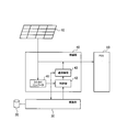
- FIG. 1 is a diagram illustrating a power management system 100 according to the first embodiment.
- FIG. 2 is a diagram illustrating the connection box 40 according to the first embodiment.
- FIG. 3 is a diagram illustrating a circuit for controlling the measuring unit 20 according to the first embodiment.
- FIG. 4 is a diagram illustrating an example of control of the operation state according to the first embodiment.
- FIG. 5 is a diagram illustrating a connection box 40 according to the first modification.
- FIG. 6 is a diagram illustrating a control example of the operation state according to the first modification.
- FIG. 7 is a diagram illustrating a control example of the operation state according to the second modification.
- FIG. 8 is a diagram illustrating a connection box 40 according to the third modification.
- FIG. 9 is a diagram illustrating a connection box 40 according to the third modification.
- the power management system includes a power supply unit, a measurement unit that measures a power generation environment of the power supply unit, and a communication unit that transmits information measured by the measurement unit.
- the power management system includes a control unit that controls the measurement unit and the communication unit.
- a power supply means is used as a power source for the measurement means and the communication means.
- the control unit determines whether or not to switch the first power threshold value used for determining whether or not to switch the operation state of the measurement unit and whether or not to switch the operation state of the communication unit based on the amount of power supplied from the power supply unit.
- a second power threshold value used for determination is set.
- control unit sets the first power threshold and the second power threshold based on the amount of power supplied from the power supply means.
- the operating state of the measuring means is switched according to the comparison result between the supplied power amount and the first power threshold value.
- operation state of the communication unit is switched according to the comparison result between the supplied power amount and the second power threshold value.
- the operation of the measuring means and the communication means can be appropriately controlled.
- the power supply means in the present invention is a means capable of generating power by itself, such as a solar cell, a wind power generator, and a hydroelectric generator.
- a solar cell is exemplified as the power supply means.
- FIG. 1 is a diagram illustrating a power management system 100 according to the first embodiment.
- the power management system 100 includes a plurality of solar cells 10, a measuring unit 20, a conversion unit 30, a plurality of connection boxes 40, a plurality of PCSs 50, an AC current collector panel 60, and a separation unit.
- a device 70, a measurement processing device 80, a communication network 110, and a server 120 are included.
- the plurality of solar cells 10 includes a solar cell group 10 1 (solar cell 10A 1 to 10X 1 ) belonging to the first group and a solar cell group 10 2 (solar cell) belonging to the second group. 10A 2 to solar cell 10X 2 ), and ... a solar cell group 10 n belonging to the nth group (solar cell 10A n to solar cell 10X n ).
- the solar cell 10 is an example of power supply means for supplying power. Specifically, the solar cell 10 generates electric power according to light such as sunlight.
- the measuring means 20 is a measuring instrument such as a sensing device, a measuring block, or a measuring instrument.
- the measuring unit 20 is, for example, a sensor that measures the power generation environment of the solar cell 10.
- the measuring means 20 is provided in the vicinity of the solar cell 10 and includes, for example, a pyranometer 20A, a thermometer 20B, and a thermocouple 20C.
- the solar radiation meter 20 ⁇ / b> A measures the amount of solar radiation applied to the solar cell 10.
- the thermometer 20 ⁇ / b> B measures the temperature in the vicinity of the solar cell 10.
- the thermocouple 20 ⁇ / b> C measures the temperature of the solar cell 10.
- the measuring means 20 may be any one of a pyranometer 20A, a thermometer 20B, and a thermocouple 20C.
- the measuring means 20 may be a measuring instrument other than the pyranometer 20A, the thermometer 20B, and the thermocouple 20C.
- the solar cell 10 is used as a power source for the measuring means 20.
- the solar cell group 10 1 it is utilized.
- the conversion unit 30 converts the information measured by the measuring means 20. Specifically, the conversion unit 30 samples the analog signal output from the measurement unit 20 and converts the analog signal into a digital signal.
- the conversion unit 30 is connected to the connection box 40 1, and outputs the measured by the measuring means 20 information on connection box 40 1.
- Each of the plurality of connection boxes 40 corresponds to each group of solar cells 10. Specifically, a plurality of junction boxes 40, a junction box 40 1 corresponding to the solar cell group 10 1, a connection box 40 2 corresponding to the solar cell group 10 2, corresponding to ... solar cell group 10 n connected and a box 40 n.
- the circuit group accommodated in each connection box 40 collects power lines extending from the plurality of solar cells 10 connected to the connection box 40. Moreover, the circuit group accommodated in each connection box 40 detects the output (output voltage and output current) of the several solar cell 10 connected to the connection box 40 separately.
- connection boxes 40 are connected to each other wirelessly or by wire.
- the outputs (output voltage and output current) of the solar cell 10 detected by the circuit groups accommodated in each connection box 40 are exchanged among the circuit groups accommodated in the plurality of connection boxes 40.
- the circuit group to be accommodated in the junction box 40 1 is connected to the conversion unit 30 obtains the measured in the measuring means 20 information from the converter 30. Further, the circuit group to be accommodated in the connection box 40 1 is connected to the measurement processing unit 80 in a wireless or wired, and transmits the measured in the measuring means 20 information to the measurement processing unit 80. In the first embodiment, communication between the connection box 40 1 and the measurement processing device 80 is performed by a PLC (Power Line Communications) utilizing a power line.
- PLC Power Line Communications
- connection box 40 The details of the circuit group accommodated in the connection box 40 will be described later (see FIG. 2).
- the solar cell 10, the measuring means 20, the conversion unit 30, and the connection box 40 are provided outdoors, for example.
- Each of the plurality of PCSs 50 corresponds to each of the plurality of connection boxes 40.
- a plurality of PCS50 has a PCS50 1 corresponding to the connection box 40 1, and PCS50 2 corresponding to the connection box 40 2, and a PCS50 n corresponding to ... connection box 40 n.
- Each PCS 50 is a device (Power Conditioning System) that converts DC power into AC power. Specifically, the PCS 50 converts the DC power supplied from the solar cell 10 into AC power, and supplies the AC power to the power system side.
- Power Conditioning System Power Conditioning System
- the PCS 50 may have a function of converting AC power into DC power.
- the PCS 50 may convert AC power supplied from the power system side into DC current and supply DC power to a storage battery (not shown).
- AC collector board 60 collects power lines extending from a plurality of PCSs 50.
- the AC current collector panel 60 supplies the AC power converted by the plurality of PCSs 50 to the power system side.
- the separation device 70 separates the signal superimposed on the current flowing through the power line.
- the separation device 70 is connected to the measurement processing device 80 wirelessly or by wire.
- the separation device 70 transmits a signal separated from the current flowing through the power line to the measurement processing device 80.
- the separation device 70 is connected via a junction box 40 1 and PCS50 1 and the power line. Separator 70 separates a signal superimposed on the current through junction box 40 1 (i.e., information measured by the measuring means 20).
- the measurement processing device 80 is a device that receives a signal from the separation device 70 and a signal from the PCS 50. For example, the measurement processing device 80 transmits information measured by the measurement unit 20 to the server 120 via the communication network 110.
- the measurement processing device 80 may include a plurality of PCSs 50.
- the measurement processing device 80 may include a plurality of PCSs 50 and an AC current collector panel 60.
- the measurement processing device 80 is a device (Energy Management System) that controls the interconnection between the plurality of solar cells 10 and the power system, and is connected to an indoor load to control the connected load. May be.
- the PCS 50, the AC current collector 60, the separation device 70, and the measurement processing device 80 are provided indoors, for example.
- the communication network 110 is a network such as the Internet, for example.
- the server 120 has a function of predicting the power generation amount of a solar cell provided in each facility.
- the server 120 controls the amount of power (reverse flow rate) output from solar cells provided in each facility.
- FIG. 2 is a diagram illustrating a circuit group accommodated in the connection box 40 according to the first embodiment.
- the connection box 40 in the first embodiment, the connection box 40 1
- the connection box 40 1 that houses a circuit group that communicates with the measurement processing device 80 will be described.
- connection box 40 includes a DC / DC converter 41, a control unit 42, and communication means 43. It should be noted that the power supplied from the solar cell 10 is supplied to the DC / DC converter 41 and the PCS 50 as shown in FIG.
- the DC / DC converter 41 is a circuit that transforms the power supplied from the solar cell 10.
- the electric power transformed by the DC / DC converter 41 is supplied to the measuring unit 20 (hereinafter including the conversion unit 30), the control unit 42, and the communication unit 43.
- the control unit 42 controls the measurement unit 20 and the communication unit 43. Specifically, the control unit 42 controls the operation state of the measurement unit 20 and the operation state of the communication unit 43 based on the amount of power supplied from the solar cell 10.
- control unit 42 detects the amount of power supplied from the solar cell 10. In the first embodiment, the control unit 42 detects the real-time power generation amount generated by the solar cell 10 as the power supply amount.
- control unit 42 sets a first power threshold used for determining whether to switch the operating state of the measuring unit 20 and a second power threshold used for determining whether to switch the operating state of the communication unit 43. To do.
- the first power threshold value may be a first operation start power threshold value used for determining whether to start the operation of the measuring unit 20, and to determine whether to stop the operation of the measuring unit 20.
- the first operation stop power threshold value may be used. Note that the first operation start power threshold and the first operation stop power threshold may be different from each other.
- the first power threshold value may be a first extended power threshold value used for determining whether or not to extend the measurement cycle of the measuring unit 20, and determining whether or not to shorten the measurement cycle of the measuring unit 20 It may be a first shortened power threshold value used for.
- the first extended power threshold and the first shortened power threshold may be different from each other.
- the second power threshold value may be a second operation start power threshold value used for determining whether or not to start the operation of the communication unit 43, and for determining whether or not to stop the operation of the communication unit 43.
- the second operation stop power threshold value may be used. Note that the second operation start power threshold and the second operation stop power threshold may be different from each other.
- the operating state of the communication unit 43 may be, for example, a state where the transmission cycle of the communication unit 43 is long (extended state) and a state where the transmission cycle of the communication unit 43 is short (shortened state).
- the second power threshold may be a second extended power threshold used for determining whether or not to extend the transmission cycle of the communication unit 43, and determining whether or not to shorten the transmission cycle of the communication unit 43. It may be a second shortened power threshold value used in the above. Note that the second extended power threshold and the second shortened power threshold may be different from each other.
- the power consumption of the communication means 43 is generally larger than the power consumption of the measurement means 20.
- control unit 42 sets a threshold lower than the second operation start power threshold as the first operation start power threshold, and sets a threshold lower than the second operation stop power threshold as the first operation stop power threshold. It is preferable. Alternatively, the control unit 42 preferably sets a threshold lower than the second extended power threshold as the first extended power threshold and sets a threshold lower than the second reduced power threshold as the first reduced power threshold.
- control unit 42 switches the operation state of the measurement unit 20 based on the comparison result between the supplied power amount (real-time power generation amount in the first embodiment) and the first power threshold value.
- control unit 42 switches the operation state of the measurement unit 20 to the ON state when the supplied power amount exceeds the first operation start power threshold value.
- control unit 42 switches the operation state of the measurement unit 20 to the OFF state when the supplied power amount is lower than the first operation stop power threshold value.
- control unit 42 switches the operation state of the measurement unit 20 to the shortened state when the supplied power amount exceeds the first shortened power threshold value.
- control part 42 switches the operation state of the measurement means 20 to an extended state, when supply electric energy is less than a 1st extended power threshold value.
- control unit 42 switches the operation state of the communication unit 43 to the ON state when the supplied power amount exceeds the second operation start power threshold value. Or the control part 42 switches the operation state of the communication means 43 to an OFF state, when supply electric energy is less than a 2nd operation stop electric power threshold value. Alternatively, the control unit 42 switches the operation state of the communication unit 43 to the shortened state when the supplied power amount exceeds the second shortened power threshold value. Or the control part 42 switches the operation state of the communication means 43 to an extended state, when supply electric energy is less than a 2nd extended power threshold value.
- the communication unit 43 is a communication device such as a communication device, a communication block, or a communication device. Specifically, the communication unit 43 transmits information measured by the measurement unit 20 to the measurement processing device 80. As described above, when the communication between the connection box 40 1 and the measurement processing device 80 performed by the PLC, the communication means 43 is such as a PLC adapter.
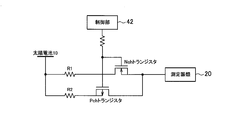
- FIG. 3 is a diagram illustrating a circuit for controlling the measuring unit 20 according to the first embodiment.
- solar cell 10 includes a power supply unit serving as a circuit for supplying a stable voltage.
- control unit 42 is connected to both the gate of the Nch transistor and the gate of the Pch transistor, and controls the gate voltage of the Nch transistor and the gate voltage of the Pch transistor at the same time.
- the resistance values of the resistor R1 and the resistor R2 are different from each other (for example, R2 ⁇ R1).
- the Nch transistor when the gate voltage of the Nch transistor and the gate voltage of the Pch transistor are larger than the threshold value, the Nch transistor is ON and the Pch transistor is OFF. Accordingly, the current flowing through the resistor R1 is supplied to the measuring means 20. That is, since the resistance value of the resistor R1 is small, a large current is supplied to the measuring means 20.
- the Nch transistor when the gate voltage of the Nch transistor and the gate voltage of the Pch transistor are smaller than the threshold value, the Nch transistor is OFF and the Pch transistor is ON. Accordingly, the current flowing through the resistor R2 is supplied to the measuring means 20. That is, a small current having a large resistance value of the resistor R2 is supplied to the measuring means 20.
- the measuring means 20 can be controlled by disposing the resistors R1 and R2 having appropriate resistance values.
- an ON state, an OFF state, an extended state, a shortened state, and the like can be considered. In any operating state, there is a period during which the measuring means 20 is not operating.
- control unit 42 controls the gate voltage of the Nch transistor and the gate voltage of the Pch transistor, thereby reducing the current (microcurrent) smaller than the predetermined threshold value. Is supplied to the measuring means 20. Thereby, failure of the measuring means 20 can be prevented.
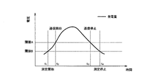
- FIG. 4 is a diagram illustrating an example of control of the operation state according to the first embodiment.
- the threshold A is the second operation start power threshold and the second operation stop power threshold
- the threshold B is the first operation start power threshold and the first operation stop power threshold.
- a real-time power generation amount generated by the solar cell 10 is used as the power supply amount.
- the control unit 42 since the power generation amount exceeds the threshold value B at time t 1 , the control unit 42 starts the operation of the measurement unit 20. Since the power generation amount exceeds the threshold A at time t 2 , the control unit 42 starts the operation of the communication unit 43. At time t 3 , since the amount of power generation falls below the threshold A, the control unit 42 stops the operation of the communication unit 43. At time t 4, the amount of power generation for below the threshold B, the control unit 42 stops the operation of the measuring means 20.
- control unit 42 sets the first power threshold value and the second power threshold value based on the supplied power amount (power generation amount) supplied from the solar cell 10.
- the operating state of the measuring means 20 is switched according to the comparison result between the supplied power amount (power generation amount) and the first power threshold value.
- the operation state of the communication unit 43 is switched according to the comparison result between the supplied power amount (power generation amount) and the second power threshold value.
- the solar cell 10 when used as a power source for the measuring means 20 and the communication means 43, the operations of the measuring means 20 and the communication means 43 can be appropriately controlled.
- the supplied power amount (power generation amount) becomes small, it is possible to control to stop the operation of the measuring unit 20 and to control the operation of the communication unit 43.
- the supplied power amount (power generation amount) becomes small, it is possible to control to extend the measurement cycle of the measuring unit 20 and to control to extend the transmission cycle of the communication unit 43.
- control unit 42 sets a threshold lower than the second operation start power threshold as the first operation start power threshold, and is lower than the second operation stop power threshold as the first operation stop power threshold. Set the threshold.
- the communication unit 43 that consumes power larger than the power consumption of the measurement unit 20 starts operating after the measurement unit 20, and the communication unit 43 stops operating before the measurement unit 20. Accordingly, it is possible to stabilize the operation of the communication unit 43 that consumes a large amount of power.
- control unit 42 sets a threshold lower than the second extended power threshold as the first extended power threshold, and sets a threshold lower than the second reduced power threshold as the first reduced power threshold.
- the communication unit 43 that consumes power larger than the power consumption of the measuring unit 20 starts the shortened state after the measuring unit 20, and the communication unit 43 stops the shortened state before the measuring unit 20. Accordingly, it is possible to stabilize the operation of the communication unit 43 that consumes a large amount of power.
- connection box 40 includes a storage battery 44 in addition to the configuration shown in FIG. 2.
- the storage battery 44 stores the electric power generated by the solar battery 10.
- FIG. 6 is a diagram illustrating a control example of the operation state according to the first modification.
- the threshold A is the second operation start power threshold and the second operation stop power threshold
- the threshold B is the first operation start power threshold and the first operation stop power threshold.
- the amount of power stored in the storage battery 44 is used as the amount of supplied power.
- the control unit 42 starts the operation of the measuring unit 20.
- the control unit 42 starts the operation of the communication unit 43.
- the control unit 42 stops the operation of the communication unit 43.
- the control unit 42 stops the operation of the measuring unit 20.
- the amount of power stored in the storage battery 44 is used as the amount of supplied power.
- both the real-time power generation amount generated by the solar battery 10 and the power storage amount stored in the storage battery 44 are used as the power supply amount.
- FIG. 7 is a diagram illustrating a control example of the operation state according to the second modification.
- the threshold A is the second operation start power threshold and the second operation stop power threshold
- the threshold B is the first operation start power threshold and the first operation stop power threshold.
- a real-time power generation amount generated by the solar cell 10 and a power storage amount stored in the storage battery 44 are used as the power supply amount.
- the first power threshold is compared with the amount of power stored in the storage battery 44.
- the second power threshold is compared with the real-time power generation amount generated by the solar cell 10.
- the control unit 42 starts the operation of the measurement unit 20. Since the power generation amount exceeds the threshold A at time t 2 , the control unit 42 starts the operation of the communication unit 43. At time t 3 , since the amount of power generation falls below the threshold A, the control unit 42 stops the operation of the communication unit 43. At time t 4 , since the amount of stored electricity falls below the threshold value B, the control unit 42 stops the operation of the measuring unit 20.
- control unit 42 switches the operation state of the measurement unit 20 based on the comparison result between the first power threshold value and the storage amount, and the control unit 42 compares the second power threshold value with the power generation amount. Based on the above, the operating state of the communication means 43 is switched.
- the operation state of the communication unit 43 that consumes power larger than the power consumption of the measuring unit 20 is controlled based on the real-time power generation amount generated by the solar cell 10. Accordingly, since the communication unit 43 operates in a state where the power is stable, it is possible to stabilize the operation of the communication unit 43 that consumes a large amount of power.
- connection box 40 has a memory 45 in addition to the configuration shown in FIG.
- the memory 45 stores information measured by the measuring unit 20.
- the memory 45 stores information measured by the measuring unit 20 during a period when the measuring unit 20 is operating and the communication unit 43 is not operating (for example, at night).
- the communication unit 43 transmits information stored in the memory 45 to the measurement processing device 80 when the operation of the communication unit 43 is performed.
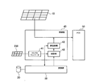
- Modification 4 illustrates a case where an auxiliary solar cell that can be used as a power source for the measurement means and the communication means is further provided.
- an auxiliary solar cell 200 that can be used as a power source for the measurement unit 20 and the communication unit 43 is provided.
- the auxiliary solar cell 200 is connected to the measurement unit 20 and the communication unit 43 and is not connected to the PCS 50.
- the auxiliary solar cell 200 is used exclusively as a power source for the measurement unit 20 and the communication unit 43.
- the power generation capability of the auxiliary solar cell 200 may be lower than the power generation capability of the solar cell 10. That is, the auxiliary solar cell 200 may be smaller than the solar cell 10.
- an auxiliary solar cell 200 that is exclusively used as a power source for the measurement unit 20 and the communication unit 43 is provided. Therefore, it is possible to stably supply power to the measurement unit 20 and the communication unit 43 regardless of the amount of power to be supplied to the PCS 50.
- control unit 42 controls the communication unit 43 to transmit information indicating the switching of the operation state of the measurement unit 20 (hereinafter, a first state flag) to the measurement processing device 80.
- control unit 42 controls the communication unit 43 to transmit information indicating the switching of the operation state of the communication unit 43 (hereinafter, a second state flag) to the measurement processing device 80.
- the first status flag is composed of 1 bit.
- the first state flag in which “0” is set is transmitted to the measurement processing device 80.
- the first state flag in which “1” is set is transmitted to the measurement processing device 80.
- the first state flag in which “0” is set is transmitted to the measurement processing device 80.
- the first state flag in which “1” is set is transmitted to the measurement processing device 80.
- the second status flag is composed of 1 bit.
- the second state flag in which “0” is set is transmitted to the measurement processing device 80.
- the second state flag in which “1” is set is transmitted to the measurement processing device 80.
- the second state flag in which “0” is set is transmitted to the measurement processing device 80.
- the second state flag in which “1” is set is transmitted to the measurement processing device 80.
- control unit 42 may control the communication unit 43 to transmit only the first state flag.
- the control unit 42 may control the communication unit 43 so as to transmit only the second state flag.
- the control unit 42 may control the communication unit 43 so as to transmit both the first state flag and the second state flag.
- the timing for transmitting the first status flag may be after the timing for switching the state of the measuring means 20.
- the timing which transmits a 1st status flag may be before the timing which the state of the measurement means 20 switches.
- the timing at which the second state flag is transmitted may be after the timing at which the state of the communication means 43 is switched. Or the timing which transmits a 2nd status flag may be before the timing which the state of the communication means 43 switches.
- the second state flag is transmitted before the timing at which the communication unit 43 switches from the ON state to the OFF state.
- the second state flag is transmitted after the timing at which the communication unit 43 is switched from the OFF state to the ON state.
- control unit 42 controls the communication unit 43 to transmit information (first state flag) indicating the switching of the operation state of the measurement unit 20 to the measurement processing device 80.
- control unit 42 controls the communication unit 43 to transmit information (second state flag) indicating switching of the operation state of the communication unit 43 to the measurement processing device 80.
- the measurement processing device 80 can determine whether an abnormality has occurred in the measurement means 20 or the communication means 43 (connection box 40) provided outdoors. Specifically, when the information on the scheduled time is not measured by the measuring unit 20, it can be determined that an abnormality has occurred in the measuring unit 20. Moreover, when information is not received at the scheduled time, it can be determined that an abnormality has occurred in the communication means 43 (connection box 40). Alternatively, when information is not received at a scheduled time, it can be determined that an abnormality has occurred in a wired or wireless communication line.
- junction box 40 for accommodating a circuit group that communicates with the measurement processing unit 80 exemplified for connection box 40 1 alone is case.
- connection box 40 1 other connection box 40 may be accommodated a circuit group for communicating with the measuring apparatus 80.
- the total of the real-time power generation amount generated by the solar cell 10 and the power storage amount stored in the storage battery 44 may be used as the power supply amount.
- the case where the power consumption is suppressed by stopping the operation of the measurement unit 20 or the communication unit 43 or extending the measurement cycle or the transmission cycle when the predetermined threshold is not exceeded has been described.
- the current supplied to the measuring means 20 and the communication means 43 may be reduced by using the circuit disclosed in FIG.
Landscapes
- Engineering & Computer Science (AREA)
- Power Engineering (AREA)
- Computer Networks & Wireless Communication (AREA)
- Charge And Discharge Circuits For Batteries Or The Like (AREA)
- Supply And Distribution Of Alternating Current (AREA)
- Remote Monitoring And Control Of Power-Distribution Networks (AREA)
- Power Sources (AREA)
Abstract
Description
実施形態に係る電力管理システムは、電力供給手段と、電力供給手段の発電環境を測定する測定手段と、測定手段によって測定された情報を送信する通信手段とを備える。電力管理システムは、測定手段及び通信手段を制御する制御部を備える。測定手段及び通信手段の電源として、電力供給手段が利用される。制御部は、電力供給手段から供給される供給電力量に基づいて、測定手段の動作状態を切り替えるか否かの判定に用いる第1電力閾値、及び、通信手段の動作状態を切り替えるか否かの判定に用いる第2電力閾値を設定する。
(電力管理システムの構成)
以下において、第1実施形態に係る電力管理システムについて、図面を参照しながら説明する。図1は、第1実施形態に係る電力管理システム100を示す図である。
以下において、第1実施形態に係る接続箱について、図面を参照しながら説明する。図2は、第1実施形態に係る接続箱40に収容される回路群を示す図である。ここでは、計測処理装置80と通信を行う回路群を収容する接続箱40(第1実施形態では、接続箱401)について説明することに留意すべきである。
以下において、第1実施形態に係る測定手段の制御例について説明する。図3は、第1実施形態に係る測定手段20を制御するための回路を示す図である。なお、本図面では「太陽電池10」と図示したが、「太陽電池10」には安定した電圧を供給するための回路となる電源部を含むものとする。
以下において、第1実施形態に係る動作状態の制御例について説明する。図4は、第1実施形態に係る動作状態の制御例を示す図である。
第1実施形態では、制御部42は、太陽電池10から供給される供給電力量(発電量)に基づいて、第1電力閾値及び第2電力閾値を設定する。言い換えると、供給電力量(発電量)と第1電力閾値との比較結果に応じて、測定手段20の動作状態が切り替わる。また、供給電力量(発電量)と第2電力閾値との比較結果に応じて、通信手段43の動作状態が切り替わる。
以下において、第1実施形態の変更例1について説明する。以下においては、第1実施形態に対する相違点について主として説明する。
以下において、変更例1に係る動作状態の制御例について説明する。図6は、変更例1に係る動作状態の制御例を示す図である。
上述したように、太陽電池10によって発電されるリアルタイムの発電量に代えて、蓄電池44に蓄積される蓄電量を用いても、第1実施形態と同様の効果が得られる。
以下において、第1実施形態の変更例2について説明する。以下においては、変更例1に対する相違点について主として説明する。
以下において、変更例2に係る動作状態の制御例について説明する。図7は、変更例2に係る動作状態の制御例を示す図である。
上述したように、太陽電池10によって発電されるリアルタイムの発電量及び蓄電池44に蓄積される蓄電量の双方を用いても、第1実施形態と同様の効果が得られる。
以下において、第1実施形態の変更例3について説明する。以下においては、第1実施形態に対する相違点について主として説明する。
以下において、第1実施形態の変更例4について説明する。以下においては、第1実施形態に対する相違点について主として説明する。
変更例4では、測定手段20及び通信手段43の電源として専用で利用する補助的太陽電池200が設けられる。従って、PCS50に供給すべき電力量に左右されずに、測定手段20及び通信手段43に対して安定的に電力を供給することができる。
以下において、第1実施形態の変更例5について説明する。以下においては、第1実施形態に対する相違点について主として説明する。
変更例5では、制御部42は、測定手段20の動作状態の切り替わりを示す情報(第1状態フラグ)を計測処理装置80に送信するように通信手段43を制御する。或いは、制御部42は、通信手段43の動作状態の切り替わりを示す情報(第2状態フラグ)を計測処理装置80に送信するように通信手段43を制御する。
本発明は上述した実施形態によって説明したが、この開示の一部をなす論述及び図面は、この発明を限定するものであると理解すべきではない。この開示から当業者には様々な代替実施形態、実施例及び運用技術が明らかとなろう。
Claims (20)
- 電力供給手段と、前記電力供給手段の発電環境を測定する測定手段と、前記測定手段によって測定された情報を送信する通信手段とを備える電力管理システムであって、
前記測定手段及び前記通信手段を制御する制御部を備え、
前記測定手段及び前記通信手段の電源として、前記電力供給手段が利用されており、
前記制御部は、前記電力供給手段から供給される供給電力量に基づいて、前記測定手段の動作状態を切り替えるか否かの判定に用いる第1電力閾値、及び、前記通信手段の動作状態を切り替えるか否かの判定に用いる第2電力閾値を設定し、
前記制御部は、前記供給電力量と前記第1電力閾値との比較結果に基づいて、前記測定手段の動作状態を切り替え、前記供給電力量と前記第2電力閾値との比較結果に基づいて、前記通信手段の動作状態を切り替えることを特徴とする電力管理システム。 - 前記電力供給手段として、太陽電池が設けられることを特徴とする請求項1に記載の電力管理システム。
- 前記第2電力閾値が前記第1電力閾値よりも大きいことを特徴とする請求項1に記載の電力管理システム。
- 前記第1電力閾値は、前記測定手段の動作を開始するか否かの判定に用いる第1動作開始電力閾値及び前記測定手段の動作を停止するか否かの判定に用いる第1動作停止電力閾値であり、
前記第2電力閾値は、前記通信手段の動作を開始するか否かの判定に用いる第2動作開始電力閾値及び前記通信手段の動作を停止するか否かの判定に用いる第2動作停止電力閾値であり、
前記制御部は、
前記第1動作開始電力閾値として、前記第2動作開始電力閾値よりも低い閾値を設定し、
前記第1動作停止電力閾値として、前記第2動作停止電力閾値よりも低い閾値を設定することを特徴とする請求項1に記載の電力管理システム。 - 前記制御部は、前記供給電力量として、前記電力供給手段によって発電されるリアルタイムの発電量を用いることを特徴とする請求項1に記載の電力管理システム。
- 前記電力供給手段によって発電される電力を蓄積する蓄電池をさらに備え、
前記制御部は、前記供給電力量として、前記蓄電池に蓄積される蓄電量を用いることを特徴とする請求項1に記載の電力管理システム。 - 前記電力供給手段によって発電される電力を蓄積する蓄電池をさらに備え、
前記制御部は、前記供給電力量として、前記電力供給手段によって発電されるリアルタイムの発電量及び前記蓄電池に蓄積される蓄電量を用いることを特徴とする請求項1に記載の電力管理システム。 - 前記第1電力閾値は、前記測定手段の測定周期を延長するか否かの判定に用いる第1延長電力閾値及び前記測定手段の測定周期を短縮するか否かの判定に用いる第1短縮電力閾値であり、
前記第2電力閾値は、前記通信手段の送信周期を延長するか否かの判定に用いる第2延長電力閾値及び前記通信手段の送信周期を短縮するか否かの判定に用いる第2短縮電力閾値であり、
前記制御部は、
前記第1延長電力閾値として、前記第2延長電力閾値よりも低い閾値を設定し、
前記第1短縮電力閾値として、前記第2短縮電力閾値よりも低い閾値を設定することを特徴とする請求項1に記載の電力管理システム。 - 前記制御部は、前記測定手段が動作しない期間において、所定閾値よりも小さい電流を前記測定手段に供給することを特徴とする請求項3に記載の電力管理システム。
- 前記制御部は、前記測定手段が動作しない期間において、所定閾値よりも小さい電流を前記測定手段に供給することを特徴とする請求項7に記載の電力管理システム。
- 前記測定手段及び前記通信手段の電源として利用可能な補助的太陽電池をさらに備え、
前記制御部は、前記供給電力量として、前記補助的太陽電池から供給される電力量を用いることを特徴とする請求項1に記載の電力管理システム。 - 前記測定手段及び前記通信手段の電源として利用可能な補助的太陽電池をさらに備え、
前記制御部は、前記供給電力量として、前記補助的太陽電池から供給される電力量を用いることを特徴とする請求項2に記載の電力管理システム。 - 電力供給手段と、前記電力供給手段の発電環境を測定する測定手段と、前記測定手段によって測定された情報を送信する通信手段とを備える電力管理システムであって、
前記測定手段及び前記通信手段を制御する制御部を備え、
前記制御部は、前記測定手段の動作状態の切り替わりを示す情報、或いは、前記通信手段の動作状態の切り替わりを示す情報を送信するように、前記通信手段を制御することを特徴とする電力管理システム。 - 電力供給手段と、前記電力供給手段の発電環境を測定する測定手段と、前記測定手段によって測定された情報を送信する通信手段とを備える電力管理システムで用いる電力管理方法であって、
前記測定手段及び前記通信手段の電源として、前記電力供給手段が利用されており、
前記電力供給手段から供給される供給電力量に基づいて、前記測定手段の動作状態を切り替えるか否かの判定に用いる第1電力閾値、及び、前記通信手段の動作状態を切り替えるか否かの判定に用いる第2電力閾値を設定するステップと、
前記供給電力量と前記第1電力閾値との比較結果に基づいて、前記測定手段の動作状態を切り替え、前記供給電力量と前記第2電力閾値との比較結果に基づいて、前記通信手段の動作状態を切り替えるステップとを備えることを特徴とする電力管理方法。 - 前記電力供給手段として、太陽電池が設けられることを特徴とする請求項14に記載の電力管理方法。
- 前記第2電力閾値が前記第1電力閾値よりも大きいことを特徴とする請求項14に記載の電力管理方法。
- 前記第1電力閾値は、前記測定手段の動作を開始するか否かの判定に用いる第1動作開始電力閾値及び前記測定手段の動作を停止するか否かの判定に用いる第1動作停止電力閾値であり、
前記第2電力閾値は、前記通信手段の動作を開始するか否かの判定に用いる第2動作開始電力閾値及び前記通信手段の動作を停止するか否かの判定に用いる第2動作停止電力閾値であり、
前記第1動作開始電力閾値として、前記第2動作開始電力閾値よりも低い閾値を設定するステップと、
前記第1動作停止電力閾値として、前記第2動作停止電力閾値よりも低い閾値を設定するステップとを備えることを特徴とする請求項14に記載の電力管理方法。 - 前記電力供給手段によって発電される電力を蓄積する蓄電池が設けられており、
前記供給電力量として、前記蓄電池に蓄積される蓄電量を用いるステップを備えることを特徴とする請求項14に記載の電力管理方法。 - 前記電力供給手段によって発電される電力を蓄積する蓄電池が設けられており、
前記供給電力量として、前記電力供給手段によって発電されるリアルタイムの発電量及び前記蓄電池に蓄積される蓄電量を用いるステップを備えることを特徴とする請求項14に記載の電力管理方法。 - 前記第1電力閾値は、前記測定手段の測定周期を延長するか否かの判定に用いる第1延長電力閾値及び前記測定手段の測定周期を短縮するか否かの判定に用いる第1短縮電力閾値であり、
前記第2電力閾値は、前記通信手段の送信周期を延長するか否かの判定に用いる第2延長電力閾値及び前記通信手段の送信周期を短縮するか否かの判定に用いる第2短縮電力閾値であり、
前記第1延長電力閾値として、前記第2延長電力閾値よりも低い閾値を設定するステップと、
前記第1短縮電力閾値として、前記第2短縮電力閾値よりも低い閾値を設定するステップとを備えることを特徴とする請求項13に記載の電力管理方法。
Priority Applications (4)
| Application Number | Priority Date | Filing Date | Title |
|---|---|---|---|
| JP2013507540A JPWO2012133249A1 (ja) | 2011-03-25 | 2012-03-23 | 電力管理システム及び電力管理方法 |
| US14/006,947 US9755431B2 (en) | 2011-03-25 | 2012-03-23 | Power management system and power management method |
| DE112012001446.4T DE112012001446B4 (de) | 2011-03-25 | 2012-03-23 | Energiemanagementsystem und Energiemanagementverfahren |
| CN201280014596.XA CN103444050B (zh) | 2011-03-25 | 2012-03-23 | 电力管理系统以及电力管理方法 |
Applications Claiming Priority (2)
| Application Number | Priority Date | Filing Date | Title |
|---|---|---|---|
| JP2011-067987 | 2011-03-25 | ||
| JP2011067987 | 2011-03-25 |
Publications (1)
| Publication Number | Publication Date |
|---|---|
| WO2012133249A1 true WO2012133249A1 (ja) | 2012-10-04 |
Family
ID=46930971
Family Applications (1)
| Application Number | Title | Priority Date | Filing Date |
|---|---|---|---|
| PCT/JP2012/057642 Ceased WO2012133249A1 (ja) | 2011-03-25 | 2012-03-23 | 電力管理システム及び電力管理方法 |
Country Status (5)
| Country | Link |
|---|---|
| US (1) | US9755431B2 (ja) |
| JP (2) | JPWO2012133249A1 (ja) |
| CN (1) | CN103444050B (ja) |
| DE (1) | DE112012001446B4 (ja) |
| WO (1) | WO2012133249A1 (ja) |
Cited By (4)
| Publication number | Priority date | Publication date | Assignee | Title |
|---|---|---|---|---|
| JP2015079799A (ja) * | 2013-10-15 | 2015-04-23 | パナソニックIpマネジメント株式会社 | 発電監視装置及び発電監視システム |
| JP2016163487A (ja) * | 2015-03-04 | 2016-09-05 | シャープ株式会社 | 充電器および充電器付きモバイル電子機器用カバー |
| JP2017022508A (ja) * | 2015-07-09 | 2017-01-26 | ローム株式会社 | 環境発電システム |
| JP2017520051A (ja) * | 2014-06-18 | 2017-07-20 | ノキア テクノロジーズ オーユー | 電子デバイス電源用の方法及び装置 |
Families Citing this family (8)
| Publication number | Priority date | Publication date | Assignee | Title |
|---|---|---|---|---|
| WO2015115654A1 (ja) | 2014-01-31 | 2015-08-06 | 株式会社フジクラ | センサノード、及びセンサノードの制御方法 |
| US9379615B2 (en) * | 2014-09-17 | 2016-06-28 | Stmicroelectronics S.R.L. | High-efficiency energy harvesting interface and corresponding energy harvesting system |
| CN106160234B (zh) * | 2016-08-27 | 2018-07-17 | 扬州科宇电力有限公司 | 一种二遥型开关监控控制器 |
| US11894715B2 (en) | 2017-09-07 | 2024-02-06 | Toyota Jidosha Kabushiki Kaisha | Charge control system and charge control method |
| JP6953997B2 (ja) * | 2017-09-07 | 2021-10-27 | トヨタ自動車株式会社 | 充電制御システム及び充電制御方法 |
| US10950313B1 (en) * | 2019-08-28 | 2021-03-16 | Micron Technology, Inc. | Responding to changes in available power supply |
| CN113489126B (zh) * | 2021-09-08 | 2021-11-16 | 成都信息工程大学 | 一种高效毫瓦级光伏能量收集控制电路 |
| EP4583346A4 (en) * | 2022-10-31 | 2025-11-12 | Contemporary Amperex Technology Hong Kong Ltd | MIXED BATTERY SYSTEM AND CONTROL METHOD AND RELATED CONTROL DEVICE, AND STORAGE SUPPORT |
Citations (3)
| Publication number | Priority date | Publication date | Assignee | Title |
|---|---|---|---|---|
| JP2003346271A (ja) * | 2002-05-28 | 2003-12-05 | Toshiba Corp | 発電付き測定通信装置 |
| JP2004221479A (ja) * | 2003-01-17 | 2004-08-05 | Kyocera Corp | 太陽光発電装置 |
| JP2010239517A (ja) * | 2009-03-31 | 2010-10-21 | Yamatake Corp | 無線センサ |
Family Cites Families (3)
| Publication number | Priority date | Publication date | Assignee | Title |
|---|---|---|---|---|
| JP2004295688A (ja) | 2003-03-27 | 2004-10-21 | Kyocera Corp | 太陽光発電装置 |
| JP4967592B2 (ja) * | 2006-10-20 | 2012-07-04 | 富士ゼロックス株式会社 | 管理システム、端末装置、情報処理装置およびプログラム |
| JP2008292319A (ja) * | 2007-05-24 | 2008-12-04 | Kobe Steel Ltd | 振動センサシステム |
-
2012
- 2012-03-23 US US14/006,947 patent/US9755431B2/en active Active
- 2012-03-23 DE DE112012001446.4T patent/DE112012001446B4/de not_active Expired - Fee Related
- 2012-03-23 WO PCT/JP2012/057642 patent/WO2012133249A1/ja not_active Ceased
- 2012-03-23 CN CN201280014596.XA patent/CN103444050B/zh not_active Expired - Fee Related
- 2012-03-23 JP JP2013507540A patent/JPWO2012133249A1/ja active Pending
-
2015
- 2015-04-06 JP JP2015077804A patent/JP5973612B2/ja not_active Expired - Fee Related
Patent Citations (3)
| Publication number | Priority date | Publication date | Assignee | Title |
|---|---|---|---|---|
| JP2003346271A (ja) * | 2002-05-28 | 2003-12-05 | Toshiba Corp | 発電付き測定通信装置 |
| JP2004221479A (ja) * | 2003-01-17 | 2004-08-05 | Kyocera Corp | 太陽光発電装置 |
| JP2010239517A (ja) * | 2009-03-31 | 2010-10-21 | Yamatake Corp | 無線センサ |
Cited By (4)
| Publication number | Priority date | Publication date | Assignee | Title |
|---|---|---|---|---|
| JP2015079799A (ja) * | 2013-10-15 | 2015-04-23 | パナソニックIpマネジメント株式会社 | 発電監視装置及び発電監視システム |
| JP2017520051A (ja) * | 2014-06-18 | 2017-07-20 | ノキア テクノロジーズ オーユー | 電子デバイス電源用の方法及び装置 |
| JP2016163487A (ja) * | 2015-03-04 | 2016-09-05 | シャープ株式会社 | 充電器および充電器付きモバイル電子機器用カバー |
| JP2017022508A (ja) * | 2015-07-09 | 2017-01-26 | ローム株式会社 | 環境発電システム |
Also Published As
| Publication number | Publication date |
|---|---|
| JP2015188308A (ja) | 2015-10-29 |
| CN103444050B (zh) | 2016-08-10 |
| CN103444050A (zh) | 2013-12-11 |
| JP5973612B2 (ja) | 2016-08-23 |
| US20140008978A1 (en) | 2014-01-09 |
| US9755431B2 (en) | 2017-09-05 |
| JPWO2012133249A1 (ja) | 2014-07-28 |
| DE112012001446T5 (de) | 2014-01-09 |
| DE112012001446B4 (de) | 2022-08-25 |
Similar Documents
| Publication | Publication Date | Title |
|---|---|---|
| JP5973612B2 (ja) | 電力管理システム及び電力管理方法 | |
| US9651971B2 (en) | Control device, power control system, and power control method | |
| CN102104257B (zh) | 公寓楼的储能系统、集成电力管理系统及系统控制方法 | |
| JP6081125B2 (ja) | 太陽光発電装置および電力管理システム、並びに、そのための電力負荷と計測装置 | |
| TWI524618B (zh) | 電能管理裝置及其操作方法 | |
| JP5475387B2 (ja) | 電力供給システムの電源最適化装置 | |
| US9300166B2 (en) | Battery management system and driving method thereof | |
| US20130207473A1 (en) | Method, system and apparatus for redirecting use of any inverter or uninterruptable power supply with improved solar power management | |
| JP2012039821A (ja) | 発電システムの電力変動緩和装置および電力変動緩和方法 | |
| KR20160023865A (ko) | 전기화학 에너지 축전기들에 전기 에너지를 저장하기 위한 방법 및 장치 | |
| KR20160001249A (ko) | 태양광 발전과 에너지 저장 시스템을 이용한 홈 에너지 관리 시스템 | |
| CN104937808B (zh) | 用于电能量存储器系统的操控设备 | |
| AU2013201284A1 (en) | A PROCESS AND APPARATUS FOR THE EFFICIENT POWER MANAGEMENT AND CONTROL OF DISTRIBUTED ENERGY SYSTEMS. The process embodies particular unique methods for capturing energy from multiple sources, primarily renewables, converting and distributing this energy into precise quanties and qualities to maximize storage efficiency and onward deployment of captured electrical energy. This process uses DC at 400-600 volts to achieve adaptability and efficiency goals. This high voltage method distribution process is unique in the invention. | |
| CN119298221A (zh) | 一种基于光伏发电的自动化调度控制系统 | |
| JP5956517B2 (ja) | エネルギー管理システム | |
| JP4711023B2 (ja) | 電圧設定装置、太陽光発電システム、および電圧設定装置の制御方法 | |
| JP4561928B1 (ja) | 電圧設定装置、太陽光発電システム、および電圧設定装置の制御方法 | |
| US9929571B1 (en) | Integrated energy storage system | |
| JP4631995B1 (ja) | 電圧設定装置、太陽光発電システム、および電圧設定装置の制御方法 | |
| KR20150011856A (ko) | 듀얼 인버터를 구비한 독립형 태양광발전 시스템 및 이로 구성되는 소규모 전력망의 전력을 계통전원과 연계하여 제어하는 중앙제어시스템 | |
| WO2015178154A1 (ja) | パワーコンディショナ及び蓄電制御方法 | |
| JP6199640B2 (ja) | 制御装置、制御システム、分電盤及び制御方法 | |
| Ribeiro et al. | Fault diagnosis in a multi-input power interface for a photovoltaic wind supply system for telecommunications | |
| KR20110063182A (ko) | 태양광 발전 시스템의 부하제어 장치 및 방법 | |
| JP2026053167A (ja) | 出力制御装置及び分散型電源システム |
Legal Events
| Date | Code | Title | Description |
|---|---|---|---|
| 121 | Ep: the epo has been informed by wipo that ep was designated in this application |
Ref document number: 12763289 Country of ref document: EP Kind code of ref document: A1 |
|
| ENP | Entry into the national phase |
Ref document number: 2013507540 Country of ref document: JP Kind code of ref document: A |
|
| WWE | Wipo information: entry into national phase |
Ref document number: 14006947 Country of ref document: US |
|
| WWE | Wipo information: entry into national phase |
Ref document number: 112012001446 Country of ref document: DE Ref document number: 1120120014464 Country of ref document: DE |
|
| 122 | Ep: pct application non-entry in european phase |
Ref document number: 12763289 Country of ref document: EP Kind code of ref document: A1 |