WO2012132994A1 - Absolute encoder device and motor - Google Patents
Absolute encoder device and motor Download PDFInfo
- Publication number
- WO2012132994A1 WO2012132994A1 PCT/JP2012/057005 JP2012057005W WO2012132994A1 WO 2012132994 A1 WO2012132994 A1 WO 2012132994A1 JP 2012057005 W JP2012057005 W JP 2012057005W WO 2012132994 A1 WO2012132994 A1 WO 2012132994A1
- Authority
- WO
- WIPO (PCT)
- Prior art keywords
- magnetic
- permanent magnet
- magnetic sensor
- encoder device
- pattern
- Prior art date
Links
Images


Classifications
-
- H—ELECTRICITY
- H02—GENERATION; CONVERSION OR DISTRIBUTION OF ELECTRIC POWER
- H02K—DYNAMO-ELECTRIC MACHINES
- H02K11/00—Structural association of dynamo-electric machines with electric components or with devices for shielding, monitoring or protection
- H02K11/20—Structural association of dynamo-electric machines with electric components or with devices for shielding, monitoring or protection for measuring, monitoring, testing, protecting or switching
- H02K11/21—Devices for sensing speed or position, or actuated thereby
- H02K11/215—Magnetic effect devices, e.g. Hall-effect or magneto-resistive elements
-
- H—ELECTRICITY
- H02—GENERATION; CONVERSION OR DISTRIBUTION OF ELECTRIC POWER
- H02K—DYNAMO-ELECTRIC MACHINES
- H02K11/00—Structural association of dynamo-electric machines with electric components or with devices for shielding, monitoring or protection
-
- G—PHYSICS
- G01—MEASURING; TESTING
- G01B—MEASURING LENGTH, THICKNESS OR SIMILAR LINEAR DIMENSIONS; MEASURING ANGLES; MEASURING AREAS; MEASURING IRREGULARITIES OF SURFACES OR CONTOURS
- G01B7/00—Measuring arrangements characterised by the use of electric or magnetic techniques
- G01B7/30—Measuring arrangements characterised by the use of electric or magnetic techniques for measuring angles or tapers; for testing the alignment of axes
-
- G—PHYSICS
- G01—MEASURING; TESTING
- G01D—MEASURING NOT SPECIALLY ADAPTED FOR A SPECIFIC VARIABLE; ARRANGEMENTS FOR MEASURING TWO OR MORE VARIABLES NOT COVERED IN A SINGLE OTHER SUBCLASS; TARIFF METERING APPARATUS; MEASURING OR TESTING NOT OTHERWISE PROVIDED FOR
- G01D5/00—Mechanical means for transferring the output of a sensing member; Means for converting the output of a sensing member to another variable where the form or nature of the sensing member does not constrain the means for converting; Transducers not specially adapted for a specific variable
- G01D5/12—Mechanical means for transferring the output of a sensing member; Means for converting the output of a sensing member to another variable where the form or nature of the sensing member does not constrain the means for converting; Transducers not specially adapted for a specific variable using electric or magnetic means
- G01D5/14—Mechanical means for transferring the output of a sensing member; Means for converting the output of a sensing member to another variable where the form or nature of the sensing member does not constrain the means for converting; Transducers not specially adapted for a specific variable using electric or magnetic means influencing the magnitude of a current or voltage
- G01D5/142—Mechanical means for transferring the output of a sensing member; Means for converting the output of a sensing member to another variable where the form or nature of the sensing member does not constrain the means for converting; Transducers not specially adapted for a specific variable using electric or magnetic means influencing the magnitude of a current or voltage using Hall-effect devices
- G01D5/145—Mechanical means for transferring the output of a sensing member; Means for converting the output of a sensing member to another variable where the form or nature of the sensing member does not constrain the means for converting; Transducers not specially adapted for a specific variable using electric or magnetic means influencing the magnitude of a current or voltage using Hall-effect devices influenced by the relative movement between the Hall device and magnetic fields
-
- G—PHYSICS
- G01—MEASURING; TESTING
- G01D—MEASURING NOT SPECIALLY ADAPTED FOR A SPECIFIC VARIABLE; ARRANGEMENTS FOR MEASURING TWO OR MORE VARIABLES NOT COVERED IN A SINGLE OTHER SUBCLASS; TARIFF METERING APPARATUS; MEASURING OR TESTING NOT OTHERWISE PROVIDED FOR
- G01D5/00—Mechanical means for transferring the output of a sensing member; Means for converting the output of a sensing member to another variable where the form or nature of the sensing member does not constrain the means for converting; Transducers not specially adapted for a specific variable
- G01D5/12—Mechanical means for transferring the output of a sensing member; Means for converting the output of a sensing member to another variable where the form or nature of the sensing member does not constrain the means for converting; Transducers not specially adapted for a specific variable using electric or magnetic means
- G01D5/244—Mechanical means for transferring the output of a sensing member; Means for converting the output of a sensing member to another variable where the form or nature of the sensing member does not constrain the means for converting; Transducers not specially adapted for a specific variable using electric or magnetic means influencing characteristics of pulses or pulse trains; generating pulses or pulse trains
- G01D5/245—Mechanical means for transferring the output of a sensing member; Means for converting the output of a sensing member to another variable where the form or nature of the sensing member does not constrain the means for converting; Transducers not specially adapted for a specific variable using electric or magnetic means influencing characteristics of pulses or pulse trains; generating pulses or pulse trains using a variable number of pulses in a train
- G01D5/2454—Encoders incorporating incremental and absolute signals
Definitions
- the present invention relates to an absolute encoder device and a motor.
- An absolute encoder device is a device that controls the rotation of the motor.
- the absolute encoder device can be used for detecting the rotational direction, rotational speed, rotational position of the motor, and the like.
- the absolute encoder device includes a magnetic type and an optical type. The magnetic type is less expensive than the optical type and has excellent environmental resistance.
- a magnetic absolute encoder device is configured by installing a magnetic sensor opposite to a two-pole permanent magnet fixed to a rotating shaft.
- a magnetic sensor a sensor using a spin valve type giant magnetoresistive element (SV-GMR) which is a magnetoresistive element is known (for example, see Patent Document 1).
- the SV-GMR type magnetic sensor has a fixed layer and a free layer, the fixed layer magnetization direction is fixed, and the free layer magnetization direction changes according to the external magnetic field direction.
- a sinusoidal signal having a phase different from each other is output when the rotation axis rotates once by a resistance change including the free layer and the fixed layer.
- the magnetization direction of the free layer rotates according to the external magnetic field, so the magnetization direction of the fixed layer used as the reference direction and the coupling of each layer (magnetostatic coupling) It is impossible to fully saturate the magnetic field of the free layer without affecting the etc.). Therefore, the operation is performed with an external magnetic field below the saturation magnetic field, and the resistance change rate is limited.
- an anisotropic magnetoresistive element which is a magnetoresistive element is provided with a bias magnet (for example, see Patent Document 2).
- AMR anisotropic magnetoresistive element
- the magnetization direction in the reference direction is a magnetic field of a stable permanent magnet, and since it is a single layer, it does not affect the coupling of each layer.
- problems such as a low resistance change rate as compared with the SV-GMR type magnetic sensor. Therefore, it is difficult to obtain high resolution and high accuracy in an absolute encoder device using only two-pole permanent magnets regardless of the type of magnetic sensor.
- Patent Document 3 and 4 there is also known an apparatus that achieves higher resolution and higher accuracy of an encoder device by using a configuration of a permanent magnet or the like instead of a type of sensor.
- a rotational position detection magnet (PG magnet) is provided on the outer peripheral surface of a rotating substrate formed in a disk shape, and a magnetic pole position detection magnet (pole magnet) is provided on the upper surface of the rotating substrate. Is provided.
- a first track that is multi-pole magnetized is formed on the outer peripheral surface of the disk-shaped rotator, and a single-pole magnet is magnetized on the lower surface of the disk-shaped rotator.
- a second track is formed.
- the devices of Patent Documents 3 and 4 are intended to obtain higher resolution and higher accuracy than the absolute encoder device using only two permanent magnets by combining two kinds of magnetic patterns. Yes.
- a position detection element that detects a magnetic field from a rotational position detection magnet separately from a substrate that supports a magnetic pole position detection element (Hall element) that detects a magnetic field from the magnetic pole position detection magnet.
- All element magnetic pole position detection element
- a substrate or a support member for supporting (MR element) is required.
- MR element magnetic pole position detection element that generates a strong magnetic field
- the magnetic field from the magnetic pole position detection magnet detects the magnetic field of the rotational position detection magnet and the magnetic field from the magnet. The detection element is affected.
- a magnetic shield plate is installed as a separate member between the magnetic pole position detection magnet and the rotation position detection magnet.
- the second track that generates a strong magnetic field is provided on the lower surface of the disk-shaped rotating body, and therefore the magnetic field from the second track is the magnetic field of the first track and the first track.
- This has a structure that affects the magnetic detection element for detecting the magnetic field from the track.
- a support member that supports the magnetic detection element that detects the magnetic field from the first track is required separately from the substrate that supports the magnetic detection element that detects the magnetic field from the second track.
- the apparatus of Patent Document 3 is configured such that the magnetic pole position detection element detects the energization position of the motor driving coil with a few pulses per rotation from the magnetic field from the magnetic pole position detection magnet.
- the magnetic detection element for detecting the magnetic field from the second track is configured to output an index signal, that is, a Z-phase signal once per rotation.
- a position detection element (Patent Document 3) and a first sensor for detecting a magnetic field from a rotational position detection magnet are used.
- Complicated arithmetic processing is required for the incremental output signal acquired from the magnetic detection element (Patent Document 4) that detects the magnetic field from the track, and components for this arithmetic processing must be provided separately.
- a counter and a battery are provided in order to hold necessary multi-rotation information.
- a counter and a battery are required to make the device of Patent Document 4 function as an absolute encoder device that detects an absolute position within one rotation.
- an object of the present invention is to provide an absolute encoder device and a motor that can be easily assembled at low cost while maintaining high resolution and high accuracy.
- One aspect of the present invention has a first magnetic pattern composed of two poles and a second magnetic pattern composed of multiple poles, a permanent magnet fixed to a rotating shaft, and the first magnetism
- the absolute angle position of the rotating shaft is determined from the first magnetic sensor for detecting the magnetic field of the pattern, the second magnetic sensor for detecting the magnetic field of the second magnetic pattern, and the output signal of the first magnetic sensor.
- An absolute angle signal indicating the relative angle position of the rotating shaft is obtained from the output signal of the second magnetic sensor, and the absolute angle signal of the rotating shaft is obtained from the absolute angle signal and the relative angle signal.
- An absolute encoder device comprising: a signal processing circuit that calculates a typical rotation angle; and a single substrate that is disposed opposite to the permanent magnet and fixes the first and second magnetic sensors and the signal processing circuit.
- said The first magnetic pattern is formed by magnetizing different polarities along the rotation direction on a surface extending in a direction intersecting the axial direction inside the concave portion formed on the surface of the permanent magnet facing the substrate,
- the magnetic pattern is formed by alternately magnetizing different polarities along the circumferential direction on the outer peripheral surface of the permanent magnet.
- “multipolar” means 4 or more.
- the first magnetic sensor is configured to output a signal having a different phase at a period in which the NS pole can be discriminated, and the second magnetic sensor outputs a signal having a phase different from the period in which the NS pole is not discriminated.
- the distance between the permanent magnet and the single substrate and the thickness of the permanent magnet are selected according to the characteristics of the first and second magnetic sensors.
- the first and second magnetic sensors include a bridge circuit constituted by a plurality of magnetoresistive elements.
- the first magnetic sensor includes a plurality of Hall elements.
- the single substrate has a flat surface extending in one direction, and the first and second sensors are directly mounted on the same plane, that is, another support member between the substrate and each sensor. It may be implemented without going through.
- the first magnetic pattern is formed in a circular shape, and the first magnetic sensor is disposed on the axis of the rotating shaft.
- the first magnetic pattern is formed in a ring shape, and the first magnetic sensor is disposed at a position offset from the axis of the rotating shaft.
- the circular shape includes a substantially circular shape having a predetermined gap between the semicircular N-pole portion and the semicircular S-pole portion.
- the ring shape includes a substantially ring shape having a predetermined gap between the half-ring-shaped N-pole portion and the half-ring-shaped S-pole portion.
- a ring-shaped magnetic body may be provided inside the permanent magnet.
- Another aspect of the present invention is a motor including the above-described absolute encoder device, and the rotating shaft is a motor driving mechanism.
- the absolute angle obtained from the first magnetic pattern by detecting the magnetic field of the first magnetic pattern composed of two poles and the magnetic field of the second magnetic pattern composed of multiple poles.
- a relative angle signal obtained from the second magnetic pattern in addition to the signal, higher resolution and higher accuracy of the encoder device are realized.
- the first magnetic pattern is formed on the surface extending in the direction intersecting the axial direction inside the concave portion of the permanent magnet and the second magnetic pattern is formed on the outer peripheral surface of the permanent magnet, the leakage of the magnetic patterns is caused. The problem of interference due to a magnetic field is reduced, and there is no need to install another member such as a magnetic shield. Therefore, it is possible to facilitate the assembly and reduce the cost.
- the first and second magnetic sensors and the signal processing circuit are fixed to a single substrate. Therefore, compared with the case where a plurality of substrates or other support members are used to support the first and second magnetic sensors and the signal processing circuit, it is possible to further contribute to the ease of assembly and cost reduction. .
- the invention according to claim 1 can realize an absolute encoder device that is easy to assemble and can be manufactured at low cost while maintaining high resolution and high accuracy.
- a signal having a different phase is output from the first magnetic sensor at a period in which the NS pole can be determined, and a signal having a different phase is output from the second magnetic sensor at a period in which the NS pole is not determined. It is configured to do. Therefore, an absolute angle signal can be obtained from signals having different phases of the first magnetic sensor, and a relative angle signal can be obtained from signals having different phases from the second magnetic sensor, so that complicated calculation processing is not required. The absolute rotation angle of the rotation axis can be obtained. In addition, it is not necessary to separately provide components for complicated arithmetic processing, which contributes to downsizing and cost reduction of the entire apparatus.
- the single of the first and second magnetic sensors can be selected.
- Each sensor and permanent magnet can be adjusted by adjusting the distance between the permanent magnet and the single substrate, adjusting the thickness of the permanent magnet, or adjusting both without changing the fixing position on the substrate.
- the magnetic field strength suitable for each sensor can be obtained. Therefore, it is possible to further facilitate the assembling work in the manufacturing process of the encoder device.
- the first and second magnetic sensors are directly mounted on the same plane of a single substrate. Therefore, when the first and second magnetic sensors are fixed to a single substrate, for example, mechanical assembly by a mounting machine (mounter) is possible, and the assembly can be further facilitated.
- the invention according to claim 4 can be applied to an absolute encoder device having a structure in which a permanent magnet is fixed to the tip of a rotating shaft.
- the invention according to claim 5 can be applied to an absolute encoder device having a rotary shaft penetrating structure.
- the invention according to claim 6 it is possible to realize a structure strong against an external stray magnetic field.
- the invention according to claim 7 can realize a motor with an absolute encoder device to which the invention according to claims 1 to 6 is applied.
- FIG. 3A is a structural diagram of a first magnetic sensor according to the first embodiment.
- B It is an equivalent circuit diagram of the structure shown in (a).
- (A) It is a wave form diagram which shows the output signal of a 1st magnetic sensor with respect to a rotation angle.
- (B) Lissajous waveform of the output signal of the first magnetic sensor.
- (C) It is a graph which shows the angle value obtained by the arc tangent from the output signal of the 1st magnetic sensor.
- (A) It is a structural diagram of the element which comprises a 2nd magnetic sensor.
- (B) It is an equivalent circuit diagram of the structure shown in (a). It is a perspective view of the permanent magnet for showing the magnetic field which a 2nd magnetic sensor detects.
- (A) It is a top view of the permanent magnet for demonstrating the detection principle of a 2nd magnetic sensor.
- FIG. (A) It is a perspective view of the absolute encoder apparatus which shows the positional relationship of the magnetic field from a 2nd magnetic pattern, and a 2nd magnetic sensor.
- FIG. (B) A perspective view of an absolute encoder device showing the positional relationship between the magnetic field from the second magnetic pattern and the second magnetic sensor when the permanent magnet shown in FIG. (A) is displaced in the axial direction of the rotating shaft. is there. It is a block diagram of the signal processing circuit which concerns on 1st Embodiment.
- (A) It is a wave form diagram which shows the output signal from a 2nd magnetic sensor.
- FIG. It is a block diagram of the motor which attached the absolute encoder apparatus which concerns on 1st Embodiment. It is sectional drawing of the absolute encoder apparatus which concerns on 2nd Embodiment. It is a top view of the absolute encoder apparatus shown in FIG.
- FIG. 6 is a structural diagram of a second magnetic sensor according to another embodiment.
- A) It is a structural diagram of the 2nd magnetic sensor which concerns on other embodiment.
- B) It is an equivalent circuit diagram of the structure shown in (a).
- (A) It is a structure figure of the 1st magnetic sensor concerning other embodiments.
- (B) It is an equivalent circuit diagram of the structure shown in (a).
- (A) It is a block diagram of the 1st magnetic sensor which concerns on other embodiment.
- (B) It is a circuit diagram of the sensor shown in (a). It is a perspective view of the permanent magnet which concerns on other embodiment. It is sectional drawing of the permanent magnet for showing the other fixing method of a rotating shaft and a permanent magnet.
- FIG. 1 is a sectional view of an absolute encoder device according to a first embodiment of the present invention
- FIG. 2 is a plan view of the encoder device shown in FIG.
- the encoder device 1 includes a substrate 8 that supports a permanent magnet 4 fixed to a rotating shaft 2, a first magnetic sensor 5, a second magnetic sensor 6, and a signal processing circuit 7.
- the permanent magnet 4 protrudes from the disc-shaped main body portion 11 having a cup shape with a protrusion formed on the lower side along the periphery and a stepped portion on the rotating shaft 2 side from the central portion of the upper surface of the main body portion 11.
- a rotating shaft fixing part 12 is provided.
- the permanent magnet 4 is fixed to the rotary shaft 2 by inserting the tip of the rotary shaft 2 into a recess provided in the central axis of the rotary shaft fixing portion 12 of the permanent magnet 4 and pressing or bonding. is doing.
- the substrate 8 is a single substrate, and is a substrate having a plane 8a extending in one direction on the same plane.
- the first and second magnetic sensors 5 and 6 are fixed on the same plane 8 a of the substrate 8.
- the substrate 8 is disposed to face the lower surface side of the permanent magnet 4 so as to cover the cup-shaped recess 13 of the permanent magnet main body 11.
- a first magnetic pattern 14 is formed on the inner upper surface 11a of the main body 11 of the permanent magnet 4 along the rotational direction of the rotation shaft toward the lower surface, and the outer peripheral surface of the main body 11 is formed along the circumferential direction.
- a second magnetic pattern 16 is formed.
- the first magnetic sensor 5 is placed on one surface 8a of the substrate 8 so as to face the first magnetic pattern 14 so as to detect the magnetic field from the first magnetic pattern 14, and the second magnetic sensor 6 is Opposed to the second magnetic pattern 16 so as to detect a magnetic field from the second magnetic pattern 16, and is disposed on the one surface 8a of the substrate 8 with a constant interval on the outer peripheral side of the permanent magnet 4. ing.
- a signal processing circuit 7 is fixed to the other surface of the substrate 8.
- FIG. 3 is a perspective view of the permanent magnet 4.
- the main body 11 of the permanent magnet 4 is configured in a cup shape in which a recess 13 is formed inside the lower surface of the disk in the positional relationship shown in FIG. A surface 11a extending in a direction intersecting the axial direction inside the permanent magnet 4 (in the positional relationship shown in FIG. 1, the concave inner surface 11a facing the substrate 8, that is, in the positional relationship shown in FIG.
- a first magnetic pattern 14 composed of two poles along the rotational direction is formed on the inner bottom surface 11a) (see FIG.
- the first magnetic pattern 14 and the second magnetic pattern 16 are formed by surface magnetization.
- the surface magnetization is a method of magnetizing a yoke close to only a surface to be magnetized.
- the second magnetic pattern 16 is formed by alternately magnetizing the south pole and the north pole in the circumferential direction on the outer peripheral surface 11b of the permanent magnet 4 in the circumferential direction.
- the magnetization method of the present embodiment is performed by surface magnetization in which only one surface is magnetized instead of double-sided magnetization in which the front and back surfaces are magnetized. That is, surface magnetization is performed only on the outer peripheral surface 11 b of the main body, and is not magnetized on the inner peripheral surface of the main body that defines the side surface of the recess 13. By surface magnetization only on the outer peripheral surface 11b of the main body, a magnetic field is generated only from the outer peripheral surface 11b of the main body, and no magnetic field is generated from the inner peripheral surface of the main body.
- the magnetic field from the second magnetic pattern 16 that is surface-magnetized on the outer peripheral surface 11 b of the main body is less likely to leak into the recess 13 of the main body 11.
- the demagnetizing field inside the resin magnet generated by the surface magnetization on the outer peripheral surface 11b of the main body is shown by a curve in FIG. Since the demagnetizing field of the second magnetic pattern 16 is generated inside the permanent magnet 4 as shown in FIG. 4, the magnetic field of the second magnetic pattern 16 magnetized on the outer peripheral surface 11 b is the cup shape of the main body 11. Leakage to the inside can be reduced.
- the first magnetic pattern 14 is not formed on the lower surface or the upper surface of the permanent magnet 4 but is formed by surface magnetization on the surface 11 a extending in the direction intersecting the axial direction inside the recess 13 formed in the permanent magnet 4. ing. Similarly to the surface magnetization of the second magnetic pattern 16, this surface magnetization is a surface magnetization that magnetizes only one surface, and the first magnetic pattern 14 is magnetized only on the surface 11a. Accordingly, the leakage magnetic field from the first magnetic pattern 14 to the outside of the main body 11 is reduced. Therefore, the leakage magnetic field of the first magnetic pattern 14 does not interfere with the second magnetic sensor 6, and the leakage magnetic field of the second magnetic pattern 16 does not interfere with the first magnetic sensor 5.
- the thickness of the permanent magnet 4 can be adjusted according to the characteristics of the first and second magnetic sensors 5 and 6. For example, when the first magnetic sensor 5 needs a stronger magnetic force, the first magnetic sensor 5 and the permanent magnet 4 are formed on the inner sides of the recesses by reducing the thickness of the permanent magnet 4. When the second magnetic sensor 6 requires a stronger magnetic force, the permanent magnet 4 can be made thicker by forming the permanent magnet 4 thicker. The magnetized area of the second magnetic pattern 16 can be increased.
- the first magnetic sensor 5 is a magnetic sensor that outputs signals having different phases at a period in which the NS pole can be determined.
- an SV-GMR type magnetic sensor is used for the first magnetic sensor 5.
- FIG. 5A is a structural diagram showing the magnetosensitive surface areas (e1 to e8) of the SV-GMR constituting the first magnetic sensor 5 and the magnetization directions (m1 to m8) of the fixed layer. ) Is a diagram showing an equivalent circuit thereof.
- the groups to be configured are arranged at 90 ° intervals on the same circumference.
- the change in resistance value in the magnetic sensitive surface area is obtained by the following equation (1).
- R R0 ⁇ Rcos ( ⁇ pin) (1)
- R0 resistance value when no external magnetic field is applied to SV-GMR
- ⁇ R resistance value change
- ⁇ magnetization direction of external magnetic field (magnetic field direction of free layer)
- ⁇ pin Magnetization direction of fixed layer
- the first magnetic sensor 5 detects the magnetic field of the first magnetic pattern 14 and outputs a two-phase sine wave signal having a phase difference of 90 degrees by one rotation for one cycle. This output becomes an absolute angle signal (absolute signal) without requiring complicated arithmetic processing.
- the first magnetic sensor 5 has output characteristics shown in FIG. 6 according to the strength of the external magnetic field. 6A shows the output of the first magnetic sensor 5 with respect to the rotation angle, FIG. 6B shows the Lissajous waveform of the output of the first magnetic sensor 5, and FIG. 2 shows an absolute angle signal obtained by converting position information obtained from one magnetic sensor 5 into an angle by arc tangent (Arctan).
- an output signal when the first magnetic sensor 5 and the first magnetic pattern 14 approach each other is indicated by a dotted line, and the first magnetic sensor 5 and the first magnetic pattern 14 are shown.
- the output signal when is separated is indicated by a solid line.
- FIG. 7A is a structural diagram of elements constituting the second magnetic sensor 6, and FIG. 7B is an equivalent circuit diagram of the structure shown in FIG. 7A.
- the second magnetic sensor 6 includes a plurality of elements shown in FIG. 7A as will be described later.
- This element has a shape in which a magnetoresistive effect element 21 having a R1 resistance formed in a vertical grid pattern and a magnetoresistive effect element 22 formed in a horizontal grid pattern having a R2 resistance are connected in series. The end of the magnetoresistive element 22 is connected to the electrode 23.
- the extending direction of the magnetoresistive effect element 22 is substantially perpendicular to the extending direction of the magnetoresistive effect element 21, and therefore the vertical direction that gives the largest resistance value change to the magnetoresistive effect element 21.
- the magnetic field in the direction is a magnetic field that gives a minimum resistance value change to the magnetoresistive element 22.
- the resistance values R1 and R2 of the magnetoresistive elements 21 and 22 are given by the following equations.
- R1 R0 ⁇ Rsin 2 ⁇ (2)
- R2 R0 ⁇ Rcos 2 ⁇ (3)
- the output Vout from the equivalent circuit is given by Substituting (2) and (3) into (4) and rearranging (5) is established.
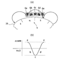
- FIG. 9A is a view of the relationship between the second magnetic pattern 16 and the magnetic field shown in FIG. 8 as viewed from the upper surface of the permanent magnet 4.
- FIG. 9A five elements (elements 6a to 6e) shown in FIG.
- a thin arrow extending in a circular arc shape from the second magnetic pattern 16 indicates a magnetic field exiting from the second magnetic pattern shown in FIG. 7, and the thick arrow shown on each element 6a to 6e. Indicates magnetic fields applied to the elements 6a to 6e.
- FIG. 9B shows signal waveforms output from the elements 6a to 6e in the positional relationship between the elements 6a to 6e and the second magnetic pattern 16 shown in FIG. 9A. Only the waveform of one of the two-phase output signals output from 6a to 6e is shown).
- the second magnetic sensor 6 is a magnetic sensor including four elements 6a to 6d arranged at positions a to d, so that the element 6a has cos and the element 6b has -Sin, -cos can be obtained from the element 6c, and a sin waveform signal can be obtained from the element 6d.
- each of the elements 6a to 6d is composed of two magnetoresistive elements whose extending directions are different from each other by about 90 degrees, and therefore, when the second magnetic pattern 16 rotates.
- the second magnetic sensor 6 outputs a two-phase sine wave signal having a phase difference of 90 degrees at a period not identifying the NS pole.
- FIG. 11 illustrates the positional relationship between the permanent magnet 4 and the second magnetic sensor 6 as viewed from the side of the encoder device 1. Since the permanent magnet 4 rotates together with the rotating shaft 2, the distance from the substrate 8 that supports the second sensor 6 may change. For example, the permanent magnet 4 having the distance g1 with the substrate 8 in FIG. 11A is shifted in the direction away from the substrate 8 and is larger than the distance g1 with respect to the substrate 8 as shown in FIG. 11B. The case where it moves to the position which has g2 is assumed. In this case, since the substrate 8 supports the magnetic sensor 6, the distance between the permanent magnet 4 and the magnetic sensor 6 varies.
- the distance between the permanent magnet 4 and the substrate 8 can be adjusted according to the characteristics of the first and second magnetic sensors 5 and 6. For example, when the first magnetic sensors 5 and 6 require a stronger magnetic force, the distance between the permanent magnet 4 and the substrate 8 may be set short.
- the first magnetic sensors 5 and 6 are mechanically mounted on the same plane 8a of the substrate 8 by a mounting machine (mounter) (see FIG. 1). When the first magnetic sensors 5 and 6 are attached, no other support member is required between the substrate 8 and the first magnetic sensors 5 and 6.
- FIG. 12 shows the configuration of the signal processing circuit 7 that executes this interpolation processing.
- the signal processing circuit 7 is realized using a CPU as an example.
- the signal processing circuit 7 receives the output of the first magnetic sensor 5 and the output of the second magnetic sensor 6.
- FIG. 13A shows the waveforms of the outputs A2 and B2 of the second magnetic sensor 6, and
- FIG. 13C shows the outputs A1 and B1 of the first magnetic sensor 5.
- the A-phase and B-phase signals having a 90-degree phase shown in FIGS. 13A and 13C are sampled at predetermined cycles, respectively, and converted into digital signals by the A / D converter 7a of the signal processing circuit 7. .
- 10-bit (2 10 ) A / D conversion is performed.
- the arc tangent calculation unit 7b obtains arc tangent (arctan) from the obtained digital signal, thereby obtaining angle data ⁇ 1 based on the output from the first sensor 5 and angle data based on the output from the second sensor 6. ⁇ 2 is calculated.
- the output signal waveform of ⁇ 2 is shown in FIG. 13B, and the output waveform signal of ⁇ 1 is shown in FIG.
- the absolute angle calculation unit 7c calculates the absolute angle data ⁇ by calculating the absolute rotation angle of the rotating shaft 2 from the angle data ⁇ 1 and the angle data ⁇ 2.
- the relationship between the angle data ⁇ 1 and the angle data ⁇ 2 is shown in FIG. If the second magnetic pattern 16 has 32 poles ( 25 poles), as shown in FIG.
- the period n of the angle data ⁇ 2 can be calculated based on the first magnetic sensor angle, that is, the value obtained by dividing the angle data ⁇ 1 by 32.
- the absolute encoder device 1 in the present embodiment detects the magnetic field of the first magnetic pattern 14 composed of two poles and the magnetic field of the second magnetic pattern 16 composed of multiple poles, By using the relative angle signal obtained from the second magnetic pattern 16 in addition to the absolute angle signal obtained from the first magnetic pattern 14, high resolution is realized, and the entire encoder device is highly accurate. .
- the first and second magnetic sensors 5 and 6 and the signal processing circuit 7 are fixed to the single substrate 8, a plurality of substrates or others are used to support the magnetic sensors 5 and 6 and the signal processing circuit 7. As compared with the case of using this support member, the assembly is facilitated and the cost is reduced.
- the permanent magnet 4 has a cup shape, the first magnetic pattern 14 is formed on the inner side of the permanent magnet 4, and the second magnetic pattern 16 is formed on the outer peripheral surface of the permanent magnet 4. The problem of interference due to the leakage magnetic field is reduced, and there is no need to install another member such as a magnetic shield. Therefore, the assembling can be facilitated and the cost can be reduced by the arrangement relationship of the two types of magnetic patterns 14 and 16 in the permanent magnet 4.
- both the first magnetic pattern 14 and the second magnetic pattern 16 are placed on the outer peripheral surface of the permanent magnet 4.
- the first magnetic sensor 5 disposed to face the first magnetic pattern 14 is in a positional relationship in which the permanent magnet 4 and the substrate 8 are accommodated in the recess 13 of the permanent magnet 4 when they are close to each other. This also contributes to the downsizing of the encoder device 1.
- the adjustment of the positional relationship between the first and second magnetic sensors 5, 6 and the permanent magnet 4 adjusts the distance between the permanent magnet 4 and the single substrate 8a to which the sensors 5, 6 are fixed. It is possible by adjusting the thickness of the permanent magnet 4 or adjusting both. Therefore, it is not necessary to change the fixing position of the first and second magnetic sensors 5 and 6 on the single substrate 8a for adjusting the positional relationship, and the assembling work is further facilitated.
- the encoder device 1 is an absolute encoder device that is easy to assemble and can be manufactured at low cost while maintaining high resolution and high accuracy.
- FIG. 15 shows the configuration of the motor and encoder device 1 when the rotating shaft 2 in the first embodiment is a motor drive mechanism. As shown in FIG. 15, by assembling the encoder device 1 to the rotating shaft 2 of the motor 30, a small motor with an absolute encoder device capable of detecting the rotating speed and rotating shaft position of the motor can be realized.
- FIG. 16 is a cross-sectional view of an absolute encoder device according to a second embodiment of the present invention
- FIG. 17 is a plan view of the encoder device shown in FIG. 16 as viewed from above.
- constituent elements corresponding to the constituent elements of the encoder apparatus 1 in the first embodiment are denoted by the same reference numerals as those in the first embodiment.
- the encoder device 31 according to the second embodiment has a structure in which the rotating shaft 2 penetrates the substrate 8. The tip of the rotating shaft 2 is inserted into the through hole 12a formed in the rotating shaft fixing portion 12 from the inside of the permanent magnet 4 through the through hole 8b formed in the center of the substrate 8, and the permanent magnet 4 is screwed. Fixed to.
- the configuration of the first magnetic pattern 14 in the encoder device 31 is shown in FIG.
- the 1st magnetic pattern 14 is formed in the ring shape along the through-hole 12a in which the rotating shaft 2 is inserted.
- the first magnetic sensor 5 is disposed at a position offset from the axis of the rotary shaft 2 while avoiding the through hole 12 a.
- FIG. 19A shows a magnetic field when the magnetized surface of the first magnetic pattern is circular
- FIG. 19B shows a magnetic field when the magnetized surface of the first magnetic pattern is ring-shaped.
- the horizontal magnetic field that the first magnetic sensor 5 needs for magnetic sensing extends to the outside of the magnetized pattern. Therefore, even if the first magnetic sensor 5 is disposed at a position offset from the axis of the rotating shaft 2, the output of the first magnetic sensor 5 is not greatly affected.
- the encoder device 31 according to the second embodiment has the same configuration as that of the encoder device 1 according to the first embodiment, except that the rotating shaft 2 penetrates the inside of the substrate 8 and the permanent magnet 4. Therefore, the encoder device 1 according to the first embodiment has the same advantages as those described above.
- the present invention is not limited to the above-described embodiments, and various modifications and changes can be made based on the technical idea of the present invention.
- the extending directions of the magnetoresistive elements 21 and 22 (see FIG. 7) in the elements 6a to 6d (see FIG. 10) constituting the second magnetic sensor 6 are formed as shown in FIG. 20 (a). You may do it.
- the magnetoresistive effect element 41 (resistance value R1) and the magnetoresistive effect element 42 (resistance value R2) have an angle of about 45 degrees with respect to the virtual center line CL.
- FIG. 20B shows an equivalent circuit corresponding to the configuration of the element shown in FIG. Since the extending directions of the magnetoresistive effect element 41 and the magnetoresistive effect element 42 are different from each other by about 90 degrees, the element shown in FIG. 20A has a phase of 90 degrees as in the element shown in FIG. Different sine wave signals are output.
- FIG. 21 shows a configuration of the second magnetic sensor 46 including four elements (46a to 46d) shown in FIG. The arrangement positions of the elements 46a to 46d are the same as the arrangement positions of the elements 6a to 6d shown in FIG.
- the second magnetic sensor 56 shown in FIG. 22 may be adopted as the second magnetic sensor.
- the structure of the second magnetic sensor 56 is shown in FIG. 22A, and its equivalent circuit is shown in 22B.
- the second magnetic sensor 56 is arranged by rotating eight magnetoresistive effect elements having outputs different in phase from each other by 45 degrees, and as shown in FIG. It has two full bridge circuits each having four magnetoresistive elements.
- cos output is obtained from the third and fifth elements whose stretching directions are different from each other by 90 degrees, and similarly, the first is different from the stretching direction by 90 degrees.
- the -cos output is obtained from the 7th element.
- the sensor group of four even-numbered elements is at a position rotated by 45 degrees with respect to the sensor group of four odd-numbered elements. Therefore, it is possible to obtain a sin output from the 6th and 8th elements whose stretching directions are 90 degrees different from each other, and similarly to obtain a ⁇ sin output from the 2nd and 4th elements whose stretching directions are 90 degrees different from each other. it can. Therefore, the output of the first full bridge circuit composed of the elements identified by the even numbers of 2, 4, 6, and 8 shown in FIG.
- each magnetoresistive element is arranged irrespective of the pitch (P) of the second magnetic pattern 16
- the second magnetic sensor 56 is also applied to the second magnetic pattern 16 having a different pitch (P). It has the advantage of being able to.
- the magnetization directions m5 to m8 shown in FIG. 5A may be 180 degrees different from the direction shown in FIG. 5A, and the magnetization directions m1 to m4 are different from those shown in FIG.
- the direction may be 180 degrees different from the direction shown in a), and all the magnetization directions m1 to m8 may be 180 degrees different from the direction shown in FIG.
- FIG. 23 (a) is a structural diagram of the AMR magnetic sensor 25 showing the AMR magnetosensitive surface area (e1 to e8) and the magnetization direction (m1 to m4) of the bias magnet
- FIG. 23 (b) is an equivalent circuit thereof.
- the groups to be configured are arranged on the same circumference at intervals of 90 degrees.
- the AMR type magnetic sensor 25 utilizes different magnetization directions that radiate from the center of the magnetic pole surface of one bias magnet. Similar to the first magnetic sensor 5, the first magnetic sensor 25 can also determine the NS pole and obtain signals with different phases in the same period as the magnetic field period.
- the first magnetic sensors 5 and 25 described above are composed of magnetoresistive elements, but the first magnetic sensor may be composed of Hall elements.
- the first magnetic sensor 35 is configured by arranging four Hall elements h1 to h4 on the same circumference at intervals of 90 degrees.
- FIG. 24B is a circuit diagram of the first magnetic sensor 35 shown in FIG. Also from the first magnetic sensor 35, NS poles can be discriminated and signals having different phases can be obtained with the same period as the magnetic field period.
- the permanent magnet 4 shown in FIG. 25 includes a ring-shaped magnetic body 50 fixed to the cup-shaped inner surface. By providing this magnetic body 50, the permanent magnet 4 has a structure that is strong against stray magnetic fields from the outside.
- FIG. 26 another fixing method of the permanent magnet 4 and the rotating shaft 2 is shown in FIG.
- a screw hole may be formed at the center, and the rotary shaft 2 may be fixed by a screw 52 from the inside of the cup shape of the permanent magnet 4.
Landscapes
- Physics & Mathematics (AREA)
- General Physics & Mathematics (AREA)
- Engineering & Computer Science (AREA)
- Power Engineering (AREA)
- Microelectronics & Electronic Packaging (AREA)
- Transmission And Conversion Of Sensor Element Output (AREA)
Abstract
Description
以下、本発明の実施の形態を添付の図により説明する。図1は、本発明の第1の実施形態に係るアブソリュートエンコーダ装置の断面図であり、図2は図1に示すエンコーダ装置を上から見た平面図である。エンコーダ装置1は、回転軸2に固定された永久磁石4と、第1の磁気センサ5と第2の磁気センサ6と信号処理回路7とを支持する基板8を備えている。永久磁石4は周縁に沿って下部側に突条部を形成したカップ形状を有する円板状の本体部11と本体部11上面中央部から回転軸2の側に段差部を形成して突出する回転軸固定部12を有している。本実施形態においては、回転軸2の先端を永久磁石4の回転軸固定部12の中心軸に設けられた凹部に挿入して、圧着又は接着することにより、永久磁石4を回転軸2に固定している。 [First Embodiment]
Embodiments of the present invention will be described below with reference to the accompanying drawings. FIG. 1 is a sectional view of an absolute encoder device according to a first embodiment of the present invention, and FIG. 2 is a plan view of the encoder device shown in FIG. The
R=R0-ΔRcos(θ-θpin)・・・(1)
R0:SV-GMRに外部磁界が印加されていない時の抵抗値
ΔR:抵抗値変化
θ:外部磁界の磁化方向(自由層の磁界方向)
θpin:固定層の磁化方向
上記(1)式の抵抗変化を有する感磁エリアを図5(a)に示すように配置することで、磁界周期と同じ周期で、NS極が判別でき且つ位相の異なる信号が得られる。 The change in resistance value in the magnetic sensitive surface area is obtained by the following equation (1).
R = R0−ΔRcos (θ−θpin) (1)
R0: resistance value when no external magnetic field is applied to SV-GMR ΔR: resistance value change θ: magnetization direction of external magnetic field (magnetic field direction of free layer)
θpin: Magnetization direction of fixed layer By arranging the magnetosensitive area having the resistance change of the above formula (1) as shown in FIG. 5A, the NS pole can be discriminated with the same period as the magnetic field period and the phase Different signals are obtained.
R1=R0-ΔRsin2 θ …(2)
R2=R0-ΔRcos2 θ …(3)
等価回路からの出力Voutは次式で与えられる

(4)式に(2)、(3)式を代入し整理すると

の(5)式が成立する。 Next, the second
R1 = R0−ΔRsin 2 θ (2)
R2 = R0−ΔRcos 2 θ (3)
The output Vout from the equivalent circuit is given by
Substituting (2) and (3) into (4) and rearranging
(5) is established.
θ=1024×(n-1)+θ2・・・(6)
n:第2の磁気センサ6からの出力信号の周期
なお、周期nは、第2の磁気センサ6からの出力信号の周期が何番目であるかを示すものであり、本実施形態では、n=1~32の整数値をとる。例えば、図14に示すように、角度データθ2が2周期目の値800である場合、1024×(2-1)+800=1824となり、1824の値が得られる。角度データθ2の周期nは、第1の磁気センサ角度、すなわち、角度データθ1を32で割った値に基づいて算出することができる。このように、本実施形態では、32極(25極)の第2の磁気パターン16を用いて、10ビットの内挿処理を行うことにより、25×210=215の絶対角度信号を得ることが出来る。 The arc
θ = 1024 × (n−1) + θ2 (6)
n: cycle of the output signal from the second
このように、エンコーダ装置1は、高分解能及び高精度を維持しながら、組み付けが容易であり安価に製造可能なアブソリュートエンコーダ装置となっている。 Further, when the first and second
Thus, the
図16は、本発明の第2の実施形態に係るアブソリュートエンコーダ装置の断面図であり、図17は図16に示すエンコーダ装置を上から見た平面図である。図16及び17に示すエンコーダ装置31において、第1の実施形態におけるエンコーダ装置1の構成要素と対応する構成要素には、第1の実施形態における符号と同様の符号を付している。第2の実施形態に係るエンコーダ装置31は、第1の実施形態に係るエンコーダ装置1と異なり、回転軸2が基板8を貫通する構造を有している。回転軸2の先端は、基板8の中心に形成された貫通孔8bを通って永久磁石4の内側から、回転軸固定部12に形成された貫通孔12aに挿入され、ネジ32によって永久磁石4に固定される。 [Second Embodiment]
16 is a cross-sectional view of an absolute encoder device according to a second embodiment of the present invention, and FIG. 17 is a plan view of the encoder device shown in FIG. 16 as viewed from above. In the
以上、本発明の実施形態について述べたが、本発明は既述の実施形態に限定されるものではなく、本発明の技術的思想に基づいて各種の変形及び変更が可能である。例えば、第2の磁気センサ6を構成するエレメント6a~6d(図10参照)の各エレメントにおける磁気抵抗効果素子21,22(図7参照)の延伸方向を図20(a)に示すように形成しても良い。図20(a)に示すエレメントにおいて、磁気抵抗効果素子41(抵抗値R1)と磁気抵抗効果素子42(抵抗値R2)は仮想中心線CLに対してそれぞれ、約45度の角度を有して延伸し、磁気抵抗効果素子42の端部は電極43と接続している。図20(a)に示すエレメントの構成に対応する等価回路を図20(b)に示す。磁気抵抗効果素子41と磁気抵抗効果素子42の延伸方向は、約90度異なっているため、図20(a)に示すエレメントからも図7(a)に示すエレメントと同様に、90度位相の異なる正弦波信号が出力される。図21に図20に示すエレメント4個(46a~46d)からなる第2の磁気センサ46の構成を示す。各エレメント46a~46dの配置位置は図10に示す各エレメント6a~6dの配置位置と同じである。 [Other Embodiments]
Although the embodiments of the present invention have been described above, the present invention is not limited to the above-described embodiments, and various modifications and changes can be made based on the technical idea of the present invention. For example, the extending directions of the
2 回転軸
4 永久磁石
5,25,35 第1の磁気センサ
6,46,56 第2の磁気センサ
7 信号処理回路
8 基板
11 永久磁石の本体部
11a 本体部の内側底面
11b 本体部の外周面
12 永久磁石の回転軸固定部
14 第1の磁気パターン
16 第2の磁気パターン DESCRIPTION OF
Claims (7)
- 2極から構成される第1の磁気パターンと、多極から構成される第2の磁気パターンとを有し、回転軸に固定された永久磁石と、
前記第1の磁気パターンの磁界を検出する第1の磁気センサと、
前記第2の磁気パターンの磁界を検出する第2の磁気センサと、
前記第1の磁気センサの出力信号から、前記回転軸の絶対角度位置を示す絶対角度信号を取得し、前記第2の磁気センサの出力信号から前記回転軸の相対角度位置を示す相対角度信号を取得し、前記絶対角度信号と前記相対角度信号から、前記回転軸の絶対的な回転角度を算出する信号処理回路と、
前記永久磁石に対向して配置され、前記第1及び第2の磁気センサと前記信号処理回路とを固定する単一基板と
を備え、
前記第1の磁気パターンは前記永久磁石の前記基板と対向する面に形成された凹部内側において軸方向と交わる方向に延びる面上に回転方向に沿って異なる極性を着磁して形成され、前記第2の磁気パターンは前記永久磁石の外周面に円周方向に沿って異なる極性を交互に着磁して形成されるアブソリュートエンコーダ装置。 A permanent magnet having a first magnetic pattern composed of two poles and a second magnetic pattern composed of multiple poles and fixed to a rotating shaft;
A first magnetic sensor for detecting a magnetic field of the first magnetic pattern;
A second magnetic sensor for detecting a magnetic field of the second magnetic pattern;
An absolute angle signal indicating the absolute angular position of the rotating shaft is obtained from the output signal of the first magnetic sensor, and a relative angle signal indicating the relative angular position of the rotating shaft is obtained from the output signal of the second magnetic sensor. A signal processing circuit for obtaining and calculating an absolute rotation angle of the rotary shaft from the absolute angle signal and the relative angle signal;
A single substrate disposed opposite to the permanent magnet and fixing the first and second magnetic sensors and the signal processing circuit;
The first magnetic pattern is formed by magnetizing different polarities along a rotational direction on a surface extending in a direction intersecting the axial direction inside a concave portion formed on a surface of the permanent magnet facing the substrate, An absolute encoder device in which the second magnetic pattern is formed by alternately magnetizing different polarities along the circumferential direction on the outer peripheral surface of the permanent magnet. - 前記第1の磁気センサは、NS極を判別できる周期で位相の異なる信号を出力するように構成され、前記第2の磁気センサは、NS極を判別しない周期で位相の異なる信号を出力するように構成され、
前記第1及び第2の磁気センサの特性に応じて、前記永久磁石と前記単一基板との間の距離と、前記永久磁石の厚さを選択したことを特徴とする請求項1に記載のアブソリュートエンコーダ装置。 The first magnetic sensor is configured to output a signal having a different phase at a period in which the NS pole can be discriminated, and the second magnetic sensor is configured to output a signal having a phase different from the period in which the NS pole is not discriminated. Composed of
The distance between the permanent magnet and the single substrate and the thickness of the permanent magnet are selected according to the characteristics of the first and second magnetic sensors. Absolute encoder device. - 前記単一基板は一方向に延びる面一の平面を有し、前記第1及び第2の磁気センサは、同一の前記平面上に直接実装されることを特徴とする請求項1に記載のアブソリュートエンコーダ装置。 The absolute circuit according to claim 1, wherein the single substrate has a flat surface extending in one direction, and the first and second magnetic sensors are directly mounted on the same flat surface. Encoder device.
- 前記第1の磁気パターンは円形状に形成され、前記第1の磁気センサは前記回転軸の軸線上に配置されていることを特徴とする請求項1に記載のアブソリュートエンコーダ装置。 The absolute encoder device according to claim 1, wherein the first magnetic pattern is formed in a circular shape, and the first magnetic sensor is disposed on an axis of the rotating shaft.
- 前記第1の磁気パターンはリング状に形成され、前記第1の磁気センサは前記回転軸の軸線上からオフセットされた位置に配置されていることを特徴とする請求項1に記載のアブソリュートエンコーダ装置。 2. The absolute encoder device according to claim 1, wherein the first magnetic pattern is formed in a ring shape, and the first magnetic sensor is disposed at a position offset from an axis of the rotating shaft. .
- 前記永久磁石の内側にリング状の磁性体を備えることを特徴とする請求項1に記載のアブソリュートエンコーダ装置。 The absolute encoder device according to claim 1, further comprising a ring-shaped magnetic body inside the permanent magnet.
- 前記回転軸はモータの駆動機構であり、請求項1~6のいずれか1項に記載のアブソリュートエンコーダ装置を備えることを特徴とするモータ。 The motor having the absolute encoder device according to any one of claims 1 to 6, wherein the rotating shaft is a motor driving mechanism.
Priority Applications (5)
| Application Number | Priority Date | Filing Date | Title |
|---|---|---|---|
| CN201280013871.6A CN103443590B (en) | 2011-03-31 | 2012-03-19 | Absolute encoder device and motor |
| ES12763244.6T ES2634588T3 (en) | 2011-03-31 | 2012-03-19 | Absolute encoding device and motor |
| EP12763244.6A EP2693169B1 (en) | 2011-03-31 | 2012-03-19 | Absolute encoder device and motor |
| KR1020137024249A KR101597639B1 (en) | 2011-03-31 | 2012-03-19 | Absolute encoder device and motor |
| US14/001,924 US9379598B2 (en) | 2011-03-31 | 2012-03-19 | Absolute encoder device and motor |
Applications Claiming Priority (2)
| Application Number | Priority Date | Filing Date | Title |
|---|---|---|---|
| JP2011-079530 | 2011-03-31 | ||
| JP2011079530A JP5840374B2 (en) | 2011-03-31 | 2011-03-31 | Absolute encoder device and motor |
Publications (1)
| Publication Number | Publication Date |
|---|---|
| WO2012132994A1 true WO2012132994A1 (en) | 2012-10-04 |
Family
ID=46930726
Family Applications (1)
| Application Number | Title | Priority Date | Filing Date |
|---|---|---|---|
| PCT/JP2012/057005 WO2012132994A1 (en) | 2011-03-31 | 2012-03-19 | Absolute encoder device and motor |
Country Status (8)
| Country | Link |
|---|---|
| US (1) | US9379598B2 (en) |
| EP (1) | EP2693169B1 (en) |
| JP (1) | JP5840374B2 (en) |
| KR (1) | KR101597639B1 (en) |
| CN (1) | CN103443590B (en) |
| ES (1) | ES2634588T3 (en) |
| TW (1) | TWI579533B (en) |
| WO (1) | WO2012132994A1 (en) |
Families Citing this family (48)
| Publication number | Priority date | Publication date | Assignee | Title |
|---|---|---|---|---|
| CN103968860B (en) * | 2013-02-01 | 2017-07-04 | 江苏多维科技有限公司 | Absolute type magnetic rotary encoder |
| JP6049570B2 (en) * | 2013-08-27 | 2016-12-21 | アルプス電気株式会社 | Rotation detector |
| JP2015129700A (en) * | 2014-01-08 | 2015-07-16 | アルプス電気株式会社 | Magnetic field rotation detection sensor and magnetic encoder |
| JP6281688B2 (en) * | 2014-02-04 | 2018-02-21 | 日立オートモティブシステムズ株式会社 | Motor control device and power steering device |
| DE102014207139A1 (en) * | 2014-04-14 | 2015-10-15 | Robert Bosch Gmbh | Measuring device for a contactless rotation angle detection |
| DE102014218060A1 (en) * | 2014-09-10 | 2016-03-10 | Robert Bosch Gmbh | Electric machine with an anchor |
| EP2950057B1 (en) * | 2014-11-18 | 2016-10-26 | Espros Photonics AG | Rotation angle sensor system |
| CN104776789A (en) * | 2015-03-26 | 2015-07-15 | 中国人民解放军国防科学技术大学 | Non-contact type two-freedom-degree position sensor |
| DE102015206108A1 (en) * | 2015-04-02 | 2016-10-20 | Bühler Motor GmbH | Magnetic donor funds |
| KR102127750B1 (en) | 2015-08-04 | 2020-06-29 | 엘지이노텍 주식회사 | Circuit board, motor and electronic power steering system |
| DE102015219865A1 (en) * | 2015-10-13 | 2017-04-13 | Lenze Drives Gmbh | Electric drive |
| TWI612278B (en) * | 2015-11-18 | 2018-01-21 | 國立清華大學 | Ring magnetic encoder, manufacturing device for ring magnetic encoder, rotary shaft offset detecting method, and human-machine interface device thereof |
| WO2017090163A1 (en) * | 2015-11-26 | 2017-06-01 | 三菱電機株式会社 | Magnetic sensor and rotation device |
| JP6755665B2 (en) * | 2016-01-21 | 2020-09-16 | キヤノン株式会社 | Motor drive, motor system and imaging device |
| DE102016101542A1 (en) * | 2016-01-28 | 2017-08-03 | Infineon Technologies Ag | sensor housing |
| FR3049704B1 (en) * | 2016-03-31 | 2020-06-05 | Ntn-Snr Roulements | SENSOR FOR DETECTION OF A PERIODIC MAGNETIC FIELD |
| US10393499B2 (en) * | 2016-05-04 | 2019-08-27 | Fastech Co., Ltd. | Angle determinating method using encoder signal with noise suppression, adjusting method for output signal of encoder and absolute encoder |
| KR101885275B1 (en) | 2016-05-04 | 2018-09-10 | 성균관대학교산학협력단 | Angle determinating method using encoder signal with noise suppression, adjusting method for output signal of encoder and absolute encoder |
| CN105958735B (en) * | 2016-06-12 | 2018-07-06 | 浙江湖州森富机电有限责任公司 | A kind of absolute encoder of tube shaped electric machine |
| WO2018025261A1 (en) * | 2016-08-02 | 2018-02-08 | Servosense (Smc) Ltd. | High resolution absolute encoder |
| US10591274B2 (en) | 2016-09-28 | 2020-03-17 | Infineon Technologies Ag | External field robust angle sensing with differential magnetic field |
| CN106787465A (en) * | 2017-02-09 | 2017-05-31 | 湖南天富机电科技有限公司 | A kind of motor rotor position detecting system based on angular transducer |
| JP6877168B2 (en) * | 2017-02-14 | 2021-05-26 | 日本電産サンキョー株式会社 | Rotary encoder and its absolute angle position detection method |
| JP6906196B2 (en) * | 2017-05-30 | 2021-07-21 | パナソニックIpマネジメント株式会社 | Electric tool |
| DE102017210675A1 (en) * | 2017-06-26 | 2018-12-27 | Bayerische Motoren Werke Aktiengesellschaft | Electric motor assembly |
| WO2019022147A1 (en) * | 2017-07-25 | 2019-01-31 | 株式会社スマートロボティクス | Reduction gear |
| CN108562326B (en) * | 2018-01-22 | 2020-06-16 | 北京玻迅基业科技有限公司 | Rotating shaft angle and speed measuring device |
| JP6996995B2 (en) * | 2018-02-02 | 2022-01-17 | Ntn株式会社 | Rotation angle detector |
| JP7067141B2 (en) * | 2018-03-08 | 2022-05-16 | Tdk株式会社 | Manufacturing method of magnet structure, rotation angle detector, electric power steering device, and magnet structure |
| US20210255003A1 (en) * | 2018-06-28 | 2021-08-19 | Agency For Science, Technology, And Research | A magnetic encoder |
| JP7255099B2 (en) * | 2018-07-09 | 2023-04-11 | 株式会社デンソー | motor |
| JP6784283B2 (en) * | 2018-09-19 | 2020-11-11 | Tdk株式会社 | Angle sensor system |
| DE102018007952B4 (en) * | 2018-10-09 | 2022-05-05 | Baumer Ivo Gmbh & Co. Kg | Device for sensory detection of rotational movements |
| DE102018219142A1 (en) * | 2018-11-09 | 2020-05-14 | Hiwin Mikrosystem Corp. | MAGNETIC ENCODER AND DEVICE WITH THE SAME |
| DE102018219144A1 (en) * | 2018-11-09 | 2020-05-14 | Hiwin Mikrosystem Corp. | MAGNETIC ENCODER AND DEVICE WITH THE SAME |
| TWI803545B (en) * | 2018-12-06 | 2023-06-01 | 日商和諧驅動系統股份有限公司 | Dual absolute encoder assembly and actuator assembly using the same |
| CN113383209B (en) | 2018-12-06 | 2024-03-29 | 谐波传动系统有限公司 | Double absolute encoder |
| CN111664778B (en) * | 2019-03-06 | 2021-10-26 | 英飞凌科技股份有限公司 | External field robust angle sensing using differential magnetic fields |
| KR102054617B1 (en) * | 2019-04-26 | 2019-12-12 | 프레스토라이트아시아 주식회사 | Sensor system having small size |
| JPWO2021044758A1 (en) * | 2019-09-05 | 2021-03-11 | ||
| CN114096797B (en) * | 2020-01-31 | 2024-03-22 | 日本精工株式会社 | Rotation angle sensor, electric power steering device, and method for manufacturing rotation angle sensor |
| KR20210115864A (en) | 2020-03-16 | 2021-09-27 | 한화테크윈 주식회사 | Magnetic sensor assembly for sensing rotational positions of a camera module |
| US11637482B2 (en) | 2020-10-08 | 2023-04-25 | Analog Devices International Unlimited Company | Magnetic sensor system for motor control |
| DE102020135115A1 (en) * | 2020-12-30 | 2022-06-30 | Webasto SE | Electric motor with position detection |
| US11460323B2 (en) | 2021-02-05 | 2022-10-04 | Analog Devices International Unlimited Company | Magnetic field sensor package |
| CN113028962B (en) * | 2021-03-09 | 2023-06-02 | 浙江禾川科技股份有限公司 | Encoder |
| WO2023118012A1 (en) * | 2021-12-20 | 2023-06-29 | Analog Devices International Unlimited Company | A magnetic sensor system |
| DE102022004808A1 (en) * | 2022-01-27 | 2023-07-27 | Sew-Eurodrive Gmbh & Co Kg | Electric motor with angle sensor |
Citations (10)
| Publication number | Priority date | Publication date | Assignee | Title |
|---|---|---|---|---|
| JPH05141911A (en) * | 1991-11-16 | 1993-06-08 | Yamaha Corp | Rotary encoder |
| JPH0610813U (en) * | 1992-07-09 | 1994-02-10 | 株式会社三協精機製作所 | Encoder device |
| JPH1070325A (en) | 1996-05-15 | 1998-03-10 | Siemens Ag | Sensor for detecting external magnetic field |
| WO2000040419A1 (en) * | 1999-01-07 | 2000-07-13 | Seiko Epson Corporation | Sensing mechanism, carriage monitor device, and printer comprising the same |
| JP2001004405A (en) | 1999-06-22 | 2001-01-12 | Sankyo Seiki Mfg Co Ltd | Magnetic encoder device |
| JP2001343206A (en) * | 2000-05-31 | 2001-12-14 | Koyo Seiko Co Ltd | Rotation angle detector, brushless motor and motor- driven power steering device |
| JP2004004028A (en) * | 2002-04-12 | 2004-01-08 | Ntn Corp | Bearing with absolute encoder |
| JP2004144497A (en) | 2002-10-22 | 2004-05-20 | Iai:Kk | Magnetic encoder and electric actuator |
| JP2006208025A (en) | 2005-01-25 | 2006-08-10 | Hamamatsu Koden Kk | Magnetic sensor |
| JP2008128740A (en) * | 2006-11-17 | 2008-06-05 | Furukawa Electric Co Ltd:The | Rotation sensor |
Family Cites Families (12)
| Publication number | Priority date | Publication date | Assignee | Title |
|---|---|---|---|---|
| US5097209A (en) * | 1990-02-21 | 1992-03-17 | The Torrington Company | Magnetic encoder and sensor system for internal combustion engines |
| JPH0610813A (en) | 1992-06-25 | 1994-01-21 | Mitsubishi Electric Corp | Starter motor |
| JP2957130B2 (en) * | 1996-06-06 | 1999-10-04 | 日立金属株式会社 | Rotational position detector |
| US6492911B1 (en) * | 1999-04-19 | 2002-12-10 | Netzer Motion Sensors Ltd. | Capacitive displacement encoder |
| JP4605352B2 (en) * | 2004-08-17 | 2011-01-05 | Nok株式会社 | Pulsar ring for magnetic rotary encoder |
| JP2006138738A (en) * | 2004-11-12 | 2006-06-01 | Yaskawa Electric Corp | Magnetic type encoder device |
| JP4706407B2 (en) * | 2005-09-14 | 2011-06-22 | 株式会社安川電機 | Magnetic encoder device |
| JP2007113931A (en) * | 2005-10-18 | 2007-05-10 | Harmonic Drive Syst Ind Co Ltd | Magnetic encoder |
| JPWO2007055135A1 (en) * | 2005-11-14 | 2009-04-30 | 株式会社安川電機 | Magnetic encoder device |
| JP5041722B2 (en) * | 2006-03-31 | 2012-10-03 | 光洋電子工業株式会社 | Absolute encoder |
| WO2008136054A1 (en) * | 2007-04-24 | 2008-11-13 | Harmonic Drive Systems Inc. | Magnetic encoder and method of detecting absolute rotational position |
| WO2009153839A1 (en) | 2008-06-20 | 2009-12-23 | 株式会社ハーモニック・ドライブ・システムズ | Magnetic encoder and actuator |
-
2011
- 2011-03-31 JP JP2011079530A patent/JP5840374B2/en active Active
-
2012
- 2012-03-19 WO PCT/JP2012/057005 patent/WO2012132994A1/en active Application Filing
- 2012-03-19 US US14/001,924 patent/US9379598B2/en active Active
- 2012-03-19 KR KR1020137024249A patent/KR101597639B1/en active IP Right Grant
- 2012-03-19 CN CN201280013871.6A patent/CN103443590B/en active Active
- 2012-03-19 EP EP12763244.6A patent/EP2693169B1/en active Active
- 2012-03-19 ES ES12763244.6T patent/ES2634588T3/en active Active
- 2012-03-28 TW TW101110798A patent/TWI579533B/en active
Patent Citations (10)
| Publication number | Priority date | Publication date | Assignee | Title |
|---|---|---|---|---|
| JPH05141911A (en) * | 1991-11-16 | 1993-06-08 | Yamaha Corp | Rotary encoder |
| JPH0610813U (en) * | 1992-07-09 | 1994-02-10 | 株式会社三協精機製作所 | Encoder device |
| JPH1070325A (en) | 1996-05-15 | 1998-03-10 | Siemens Ag | Sensor for detecting external magnetic field |
| WO2000040419A1 (en) * | 1999-01-07 | 2000-07-13 | Seiko Epson Corporation | Sensing mechanism, carriage monitor device, and printer comprising the same |
| JP2001004405A (en) | 1999-06-22 | 2001-01-12 | Sankyo Seiki Mfg Co Ltd | Magnetic encoder device |
| JP2001343206A (en) * | 2000-05-31 | 2001-12-14 | Koyo Seiko Co Ltd | Rotation angle detector, brushless motor and motor- driven power steering device |
| JP2004004028A (en) * | 2002-04-12 | 2004-01-08 | Ntn Corp | Bearing with absolute encoder |
| JP2004144497A (en) | 2002-10-22 | 2004-05-20 | Iai:Kk | Magnetic encoder and electric actuator |
| JP2006208025A (en) | 2005-01-25 | 2006-08-10 | Hamamatsu Koden Kk | Magnetic sensor |
| JP2008128740A (en) * | 2006-11-17 | 2008-06-05 | Furukawa Electric Co Ltd:The | Rotation sensor |
Non-Patent Citations (1)
| Title |
|---|
| See also references of EP2693169A4 * |
Also Published As
| Publication number | Publication date |
|---|---|
| JP2012215415A (en) | 2012-11-08 |
| EP2693169A1 (en) | 2014-02-05 |
| US9379598B2 (en) | 2016-06-28 |
| CN103443590B (en) | 2016-04-13 |
| US20140015384A1 (en) | 2014-01-16 |
| JP5840374B2 (en) | 2016-01-06 |
| TW201303266A (en) | 2013-01-16 |
| TWI579533B (en) | 2017-04-21 |
| ES2634588T3 (en) | 2017-09-28 |
| KR20130135918A (en) | 2013-12-11 |
| KR101597639B1 (en) | 2016-02-25 |
| EP2693169B1 (en) | 2017-05-03 |
| CN103443590A (en) | 2013-12-11 |
| EP2693169A4 (en) | 2014-08-27 |
Similar Documents
| Publication | Publication Date | Title |
|---|---|---|
| JP5840374B2 (en) | Absolute encoder device and motor | |
| JP5120384B2 (en) | Rotation angle detection device, rotator, and rotation angle detection method | |
| JP5666886B2 (en) | Rotary encoder | |
| EP3184954B1 (en) | Magnetoresistive angle sensor | |
| JP4324813B2 (en) | Rotation angle detector and rotating machine | |
| US8400096B2 (en) | Magnetic encoder and actuator | |
| JP4319153B2 (en) | Magnetic sensor | |
| JP5893134B2 (en) | Magnetic rotation angle detector | |
| US20100301845A1 (en) | Absolute measurement steering angle sensor arrangement | |
| GB2505226A (en) | Arrangement, method and sensor for measuring an absolute angular position using a multi-pole magnet | |
| JP5131537B2 (en) | Angle detector | |
| JPWO2007055135A1 (en) | Magnetic encoder device | |
| JP5201493B2 (en) | Position detection device and linear drive device | |
| US8928313B2 (en) | Magnetic encoder with improved resolution | |
| JP4900838B2 (en) | Position detection device and linear drive device | |
| JP2009244044A (en) | Magnetic rotational position detection device | |
| JP2015072253A (en) | Rotation detection sensor and manufacturing method thereof | |
| JP2003262537A (en) | Rotational angle sensor | |
| JP2005172441A (en) | Angle and angular velocity integrated detector | |
| JP2005030959A (en) | Magnetic encoder device | |
| JP2005017056A (en) | Magnetic encoder device | |
| JP2012145525A (en) | Rotary encoder and motor |
Legal Events
| Date | Code | Title | Description |
|---|---|---|---|
| 121 | Ep: the epo has been informed by wipo that ep was designated in this application |
Ref document number: 12763244 Country of ref document: EP Kind code of ref document: A1 |
|
| WWE | Wipo information: entry into national phase |
Ref document number: 14001924 Country of ref document: US |
|
| ENP | Entry into the national phase |
Ref document number: 20137024249 Country of ref document: KR Kind code of ref document: A |
|
| NENP | Non-entry into the national phase |
Ref country code: DE |
|
| REEP | Request for entry into the european phase |
Ref document number: 2012763244 Country of ref document: EP |
|
| WWE | Wipo information: entry into national phase |
Ref document number: 2012763244 Country of ref document: EP |