WO2012132481A1 - Color conversion device, color conversion method, program, and color separation device - Google Patents
Color conversion device, color conversion method, program, and color separation device Download PDFInfo
- Publication number
- WO2012132481A1 WO2012132481A1 PCT/JP2012/050049 JP2012050049W WO2012132481A1 WO 2012132481 A1 WO2012132481 A1 WO 2012132481A1 JP 2012050049 W JP2012050049 W JP 2012050049W WO 2012132481 A1 WO2012132481 A1 WO 2012132481A1
- Authority
- WO
- WIPO (PCT)
- Prior art keywords
- color
- granularity
- conversion
- unit
- target value
- Prior art date
Links
Images


Classifications
-
- H—ELECTRICITY
- H04—ELECTRIC COMMUNICATION TECHNIQUE
- H04N—PICTORIAL COMMUNICATION, e.g. TELEVISION
- H04N1/00—Scanning, transmission or reproduction of documents or the like, e.g. facsimile transmission; Details thereof
- H04N1/40—Picture signal circuits
- H04N1/40012—Conversion of colour to monochrome
-
- H—ELECTRICITY
- H04—ELECTRIC COMMUNICATION TECHNIQUE
- H04N—PICTORIAL COMMUNICATION, e.g. TELEVISION
- H04N1/00—Scanning, transmission or reproduction of documents or the like, e.g. facsimile transmission; Details thereof
- H04N1/46—Colour picture communication systems
- H04N1/56—Processing of colour picture signals
- H04N1/60—Colour correction or control
- H04N1/6016—Conversion to subtractive colour signals
- H04N1/6022—Generating a fourth subtractive colour signal, e.g. under colour removal, black masking
Definitions
- the present invention relates to a color conversion device, a color conversion method, a program, and a color separation device for converting the color of a printed matter formed using a plurality of types of color materials.
- CMYK ink CMYK ink
- Japanese Patent Application Laid-Open No. 2000-78418 discloses a method and apparatus for determining a use amount of K toner by predicting an image quality prediction value related to the image quality of an image printed out from a detected predetermined color signal. .
- Japanese Unexamined Patent Application Publication No. 2009-241609 discloses an apparatus and method for determining whether or not to form chromatic (or achromatic) dots based on an input signal. For example, it is described that dots are formed using light K ink instead of dark K ink in a color region where the dot shape is conspicuous and graininess deteriorates.
- the present invention has been made to solve the above-described problems, and an object of the present invention is to provide a color conversion device, a color conversion method, and a program capable of forming a printed material that achieves both improved graininess and reduced cost.
- the color conversion device is a device for converting the color of a printed matter formed using a plurality of types of color materials, and for inputting a device color signal associated with the amount of use of each color material.
- a target value setting unit that sets a target value of the granularity for each granularity adjustment region extracted by the adjustment region extraction unit, and a granularity calculation unit that calculates the granularity in each granularity adjustment region
- the granularity calculated by the granularity calculating unit is closer to the target value set by the target value setting unit than before the conversion, and the same color in the device-independent color space Fit in range So that the, and having a color matching conversion section for converting the device color signal of the granularity adjustment region to the new device color signal.
- the adjustment area extraction unit that extracts at least one granularity adjustment area for adjusting the granularity of the image from the image area represented by the input device color signal, and each of the extracted granularity adjustment areas.
- the color matching conversion unit converts the device color signal so that the total use amount of each color material in the granularity adjustment region is larger than that before the conversion. Is preferred.
- the plurality of types of color materials include an achromatic color material and a plurality of chromatic color materials, and the color on the printed matter by the achromatic color material can be reproduced by combining the plurality of chromatic color materials.
- the color matching unit reduces the amount of the achromatic color material used in the granularity adjustment region before conversion, and converts the total amount of the chromatic color materials in the granularity adjustment region. It is preferable to convert the device color signal so as to increase more than before. In this way, by increasing the total amount of each color material used for the formation of the printed material, the desired granularity adjustment region while appropriately reducing the granularity and appropriately increasing the amount of color material used. Can be obtained.
- the color matching conversion unit converts the device color signal so that the total amount of each color material used in the granularity adjustment region is smaller than that before conversion. Is preferred.
- the plurality of types of color materials include an achromatic color material and a plurality of chromatic color materials, and the color on the printed matter by the achromatic color material can be reproduced by combining the plurality of chromatic color materials.
- the color matching unit increases the usage amount of the achromatic color material in the granularity adjustment region before conversion, and converts the total usage amount of the plurality of chromatic color materials in the granularity adjustment region. It is preferable to convert the device color signal so that it is smaller than before. In this way, by reducing the total amount of each color material used to form the printed material, the granularity is appropriately increased, and the amount of the color material used is appropriately decreased, while being desired in the granularity adjustment region. Can be obtained.
- the adjustment area extraction unit extracts a face area as the granularity adjustment area.
- the adjustment area extraction unit extracts an achromatic flat area whose saturation is lower than the first threshold and whose spatial frequency is lower than the second threshold as the granularity adjustment area.
- the color conversion method is a method for converting the color of a printed matter formed using a plurality of types of color materials, and is an input for inputting device color signals respectively associated with the usage amounts of the color materials.
- An extraction step of extracting at least one granularity adjustment region for adjusting the granularity of the image from the image region represented by the input device color signal, and for each of the extracted granularity adjustment regions A setting step for setting each target value of the granularity, a calculation step for calculating the granularity in each granularity adjustment region, and the calculated granularity is set to the target before the conversion.
- a program according to the present invention is a program for converting the color of a printed matter formed using a plurality of types of color materials, and the computer outputs device color signals respectively associated with the usage amounts of the color materials.
- An input color signal input unit an adjustment region extraction unit that extracts at least one granularity adjustment region for adjusting the granularity of an image from the image region represented by the device color signal input by the color signal input unit;
- a target value setting unit that sets a target value of the granularity for each granularity adjustment region extracted by the adjustment region extraction unit, and a granularity calculation unit that calculates the granularity in each granularity adjustment region
- the granularity calculated by the granularity calculating unit is closer to the target value set by the target value setting unit than before conversion, and is a device-independent color. To fit the color matching range over between, characterized in that to function as the color matching conversion section for converting the device color signal of the granularity adjustment region to the new device color signal.
- the plate separation apparatus includes an adjustment region extraction unit that extracts at least one granularity adjustment region for adjusting the granularity of an image from an image region represented by an input device color signal, and the adjustment region extraction A target value setting unit that sets a target value of the granularity for each granularity adjustment region extracted by a unit, a granularity calculation unit that calculates the granularity in each granularity adjustment region, Separation that determines one separation condition information from among a plurality of separation condition information that separates the input device color signal into device color signals that are associated with the usage amounts of multiple types of color materials.
- a condition determining unit wherein the color separation condition determining unit is configured such that the granularity calculated by the granularity calculating unit is set by the target value setting unit more than other color separation conditions. The one minute so that it is close to the value And determining the condition information.
- At least one granularity adjustment region for adjusting the granularity of an image is extracted from the image region represented by the input device color signal, and extracted.
- a target value of the granularity is set for each of the granularity adjustment areas, and the granularity in each granularity adjustment area is calculated, and the granularity is closer to the target value than before the conversion.
- the device color signal in the degree adjustment area was converted.
- At least one granularity adjustment region for adjusting the granularity of the image is extracted from the image region represented by the input device color signal, and each of the extracted granularities is extracted.
- a granularity target value is set for each of the adjustment areas, the granularity is calculated in each granularity adjustment area, and a plurality of color separations are made so as to be closer to the target value than other color separation conditions.
- One separation condition information was decided from the condition information.
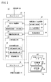
- FIG. 1 is an electrical schematic block diagram of a color conversion apparatus according to a first embodiment.
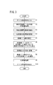
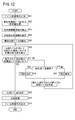
- 3 is a flowchart for explaining the operation of the color conversion apparatus shown in FIG. 2.
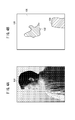
- FIG. 4A is a schematic diagram in which an image represented by a device color signal is visualized.
- FIG. 4B is a schematic explanatory diagram showing the result of extracting the granularity adjustment region by the adjustment region extraction unit of FIG.
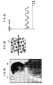
- FIG. 5A is a schematic explanatory diagram showing a correspondence relationship between ink types and their usage before each conversion.
- FIG. 5B is a schematic explanatory diagram showing the correspondence between the ink type after GCR conversion and the amount of use.
- FIG. 5C is a schematic explanatory diagram showing the correspondence between the ink type after IGCR conversion and the amount used.
- FIG. 6A is a schematic explanatory diagram showing a uniform color range on a device-independent color space.
- FIG. 6B is a schematic explanatory diagram illustrating a specification example of a candidate table group.
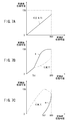
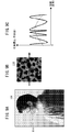
- FIG. 7A is a graph illustrating conversion characteristics of a normal color conversion table that reproduces the gray color.
- FIG. 7B is a graph illustrating the conversion characteristics of the GCR conversion table that reproduces the gray color.
- FIG. 7C is a graph illustrating conversion characteristics of an IGCR conversion table that reproduces the gray color.
- FIG. 8A is a schematic explanatory diagram showing a rectangular area outside the granularity adjustment area.
- FIG. 8A is a schematic explanatory diagram showing a rectangular area outside the granularity adjustment area.
- FIG. 8B is a partially enlarged view of the rectangular area shown in FIG. 8A.
- FIG. 8C is a graph showing a microscopic density profile along the arrow shown in FIG. 8B.
- FIG. 9A is a schematic explanatory diagram showing a rectangular area in the granularity adjustment area.
- FIG. 9B is a partially enlarged view of the rectangular area shown in FIG. 9A.
- FIG. 9C is a graph showing a microscopic density profile along the arrow shown in FIG. 9B.
- It is an electrical schematic block diagram of the plate separation apparatus which concerns on 2nd Embodiment. 12 is a flowchart provided for explaining the operation of the plate separation apparatus shown in FIG.
- FIG. 1 is a schematic explanatory diagram of a printing system 10 incorporating a color conversion device 12 according to the first embodiment (or a color separation device 12A according to the second embodiment).
- the printing system 10 basically includes a color conversion device 12, an image forming device 14, a DTP (Desktop Publishing) device 16, and a database server 18.
- the color conversion device 12, the DTP device 16, and the database server 18 are electrically connected to each other by wire or wireless.
- the color converter 12 converts input image data (device color signal or page description data) from an external device into a device color signal suitable for printing by the image forming apparatus 14. Further, the color conversion device 12 outputs the converted device color signal to the image forming device 14 side.
- the device color signal means a color signal defined by device-dependent data. For example, raster format data (TIFF, bitmap, RAW) having four (CMYK) or three (RGB) color channels. Etc.).
- raster format data TIFF, bitmap, RAW
- CMYK color signal
- RGB three
- the image forming apparatus 14 is electrically connected to the color conversion apparatus 12.
- a serial interface such as USB (Universal Serial Bus), IEEE 1394, Ethernet (registered trademark), a wireless network, or a parallel interface such as Centronics can be applied.
- the image forming apparatus 14 is a so-called inkjet printer that forms an image on the medium by ejecting ink droplets from the recording head 20 while conveying a medium (recording medium) (not shown) in a predetermined direction.
- a medium recording medium
- the substrate of the media paper such as synthetic paper, cardboard, and aluminum vapor-deposited paper, resin such as vinyl chloride and PET, tarpaulin, and the like can be used.
- the recording head 20 has four types of color materials of different colors ⁇ C ink 22c (chromatic color material), M ink 22m (chromatic color material), Y ink 22y (chromatic color material), and K ink 22k (achromatic color material) ⁇ .
- C ink 22c chromatic color material
- M ink 22m chromatic color material
- Y ink 22y chromatic color material
- K ink 22k achromatic color material
- Each line head 24c, 24m, 24y, 24k is formed with a plurality of nozzles (not shown) arranged along the width direction of the medium.
- the C ink 22c, M ink 22m, Y ink 22y, and K ink 22k are accommodated in ink tanks 26c, 26m, 26y, and 26k as containers, respectively.
- the line head 24c discharges the C ink 22c supplied from the ink tank 26c through the plurality of nozzles.
- the line head 24m discharges the M ink 22m supplied from the ink tank 26m through the plurality of nozzles.
- the line head 24y discharges the Y ink 22y supplied from the ink tank 26y through the plurality of nozzles.
- the line head 24k discharges the K ink 22k supplied from the ink tank 26k through the plurality of nozzles.
- various methods can be adopted as a mechanism for ejecting the droplets of the ink 22 by the recording head 20.
- a method of ejecting ink 22 droplets by deformation of an actuator constituted by a piezoelectric element (piezoelectric element) or the like may be applied.
- a thermal jet method may be applied in which bubbles are generated by heating the ink 22 through a heating element such as a heater and the droplets of the ink 22 are ejected with the pressure.
- the recording head 20 is not limited to a line head, and may be a multi-pass method in which an image is formed while reciprocating scanning in the width direction of the medium.
- the DTP device 16 can edit a material composed of characters, figures, patterns, photographs, and the like, and generates an electronic manuscript in a page description language (hereinafter referred to as PDL) by arranging the material for each page.
- PDL is a language that describes image information such as text, graphics, and other format information, position information, and color information (including density information) within a “page” that is an output unit for printing and display.
- the DTP device 16 performs rasterization processing on the electronic document in the PDL format. This rasterization processing includes rasterization processing for converting from the PDL format to the raster format, and color conversion processing using an ICC (International Color Consortium) profile.
- ICC International Color Consortium
- the database server 18 is a device for managing data such as a job ticket for an electronic document ⁇ eg, JDF (Job Definition Format) file ⁇ , color sample data, target profile, or a printing profile suitable for a combination of the image forming apparatus 14 and media. It is.
- JDF Job Definition Format
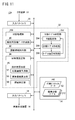
- FIG. 2 is an electrical schematic block diagram of the color conversion device 12 shown in FIG.
- the color conversion device 12 includes an input interface 30 (color signal input unit), a control unit 32, a memory 34 (recording medium), and an output interface 36.
- the memory 34 stores a program for causing the color conversion device 12 (the color separation device 12A) according to the first embodiment (or the second embodiment) to function.
- the input interface 30 receives an electrical signal from an external device. For example, device color signals and PDL data edited and created by the DTP device 16 are acquired. Further, various information such as an ICC profile stored in the database server 18 is acquired.
- the output interface 36 transmits an electrical signal to an external device.
- the device color signal subjected to the color conversion processing according to the present invention is supplied to the image forming apparatus 14.
- This color conversion process is a process for converting only the signal value of the device color signal without changing the type of color plate (for example, CMYK signal data).
- the device color signal before conversion may be referred to as “pre-conversion color signal”
- the device color signal after conversion may be referred to as “post-conversion color signal”.
- the input / output device color signals are associated with the amount of ink 22 used in the image forming apparatus 14. This association can be arbitrarily designed for each color channel. For example, a usage amount of 0% may be assigned at the lowest gradation level, a usage amount of 100% may be assigned at the highest gradation level, and a usage amount may be assigned linearly at an intermediate level.
- the control unit 32 configured by an information processing device such as a CPU includes a rasterization processing unit 38, an analysis image data creation unit 40, an adjustment region extraction unit 42, a target value setting unit 44, and a granularity calculation unit 46.
- the color conversion table determination unit 48 and the color matching conversion unit 50 are provided.
- the rasterization processing unit 38 has the same rasterization function as the DTP device 16.
- the rasterization processing unit 38 performs rasterization processing on the input data according to the type of input data. When the device color signal is directly input to the input interface 30 side, the rasterizing process by this component is not necessary.
- the analysis image data creation unit 40 creates analysis image data from the pre-conversion color signal acquired from the input interface 30 or the rasterization processing unit 38. Specifically, the analysis image data creation unit 40 performs color conversion processing for converting the pre-conversion color signal into device-independent data.
- the device-independent data is data defined by a color system such as HSV (Hue-Saturation-Value), HLS (Hue-Lightness-Saturation), CIELAB, CIEUV, and XYZ.
- the analysis image data creation unit 40 creates L * a * b * data, YCC data, and the like from the pre-conversion color signal using, for example, a print profile corresponding to the image forming apparatus 14.
- the adjustment area extraction unit 42 extracts a granularity adjustment area for adjusting the granularity of the image (hereinafter sometimes simply referred to as “granularity GR”) from a predetermined image area.
- granularity GR a granularity adjustment area for adjusting the granularity of the image
- the target value setting unit 44 sets the target value Gt of the granularity GR for each of the granularity adjustment regions extracted by the adjustment region extraction unit 42.
- the target value Gt may be set according to the attribute of the granularity adjustment region, or may be set with an input operation by the user via the GUI.
- the granularity calculation unit 46 calculates the granularity GR in the granularity adjustment region based on the device color signal and the output characteristics of the image forming apparatus 14.
- the granularity calculation unit 46 predicts the print density (microscopic density profile) based on the device color signal and the output characteristics of the image forming apparatus 14, and the print density prediction unit 52.
- the standard deviation calculation unit 54 that calculates the standard deviation of the print density in a predetermined image area based on the microscopic density profile predicted in step S5, and the standard deviation of the print density calculated by the standard deviation calculation unit 54 is corrected.
- the visual correction unit 56 is configured to acquire the granularity GR as an index associated with the visibility (granularity) of the image.
- the color conversion table determination unit 48 designates a plurality of color conversion tables (hereinafter may be referred to as candidate tables) that can be used for color conversion processing, and also stores a plurality of candidate tables (hereinafter referred to as candidate table groups). Select and determine one color conversion table from among them.
- the color conversion table determination unit 48 includes a granularity comparison unit 58 that compares and evaluates the granularity GR calculated by the granularity calculation unit 46 and the target value Gt set by the target value setting unit 44.
- a table selection unit 60 that selects one color conversion table from the candidate table group based on the comparison / evaluation result in the granularity comparison unit 58 is further provided.
- the color matching conversion unit 50 uses a color conversion table having a predetermined data format to generate a new device color to output the input device color signal so as to be within the color matching range on the device independent color space. Convert to signal. Depending on the type of the color conversion table, either IGCR (Inverse Gray-Component Replacement) conversion, GCR (Gray-Component Replacement) conversion, or equivalent conversion is executed. As in the image forming apparatus 14 shown in FIG. 1, by combining a plurality of chromatic color materials C ink 22c, M ink 22m, and Y ink 22y, the color on the printed matter 28 by the K ink 22k that is an achromatic color material is changed. If reproducible, IGCR conversion and GCR conversion are effective. Details of GCR conversion and IGCR conversion will be described later.
- the memory 34 records print profile data 62 suitable for the image forming apparatus 14, an IGCR conversion table 64 used for IGCR conversion, and a GCR conversion table 66 used for GCR conversion.
- the memory 34 may record pre-conversion color signals, post-conversion color signals, analysis image data, and various types of information necessary for color conversion processing according to the present invention.
- the color conversion device 12 according to the first embodiment is configured as described above. Next, the operation of the color conversion device 12 will be described with reference to the flowchart of FIG.
- the color conversion device 12 inputs a device color signal via the input interface 30 (step S1). For example, two input forms are assumed.
- the DTP device 16 performs a rasterization process on a PDL-format electronic document created through a predetermined editing process, thereby providing a device color signal (that is, CMYK signal data) used for printing. Is created in advance. Then, the color conversion device 12 inputs the device color signal supplied from the DTP device 16 via the input interface 30.
- a device color signal that is, CMYK signal data
- the DTP device 16 creates an electronic document in PDL format through a predetermined editing process, and supplies the electronic document to the image forming apparatus 14 side in the PDL format.
- the rasterization processing unit 38 reads the print profile data 62 stored in the memory 34 and performs a rasterization process on the input electronic document (PDL format), whereby a device color signal (that is, a print color data) , CMYK signal data).
- the analysis image data creation unit 40 creates analysis image data by performing a predetermined color conversion process on the input device color signal (step S2).
- the analysis image data creation unit 40 creates, for example, YCC data used for a face detection process described later, L * a * b * data used for a color matching conversion process described later, and the like.
- the input device color signal and the generated analysis image data are temporarily recorded in the memory 34.
- the adjustment area extraction unit 42 extracts a granularity adjustment area for adjusting the granularity GR of the image from the image area represented by the device color signal (step S3).
- the adjustment area extraction unit 42 reads the device color signal and the analysis image data from the memory 34, and then extracts the granularity adjustment area by applying various area detection algorithms. A specific example of the algorithm will be described below.
- the detected face area may be set as the granularity adjustment area. This is because the human face is a typical object that is easily evaluated for its quality.
- various known image processing techniques disclosed in Japanese Patent Application Laid-Open Nos. 2006-285959 and 2007-148537 may be applied.
- the type of analysis image data used for this detection is not limited.
- a known detection method mounted in an input device such as a digital camera can be applied as it is.
- an achromatic flat region may be set as the granularity adjustment region.
- the human standard visual response characteristic (contrast resolution) is maximized because the color is gray and the spatial frequency band is around 1 Cy / mm.
- the achromatic color flat region refers to an image region whose saturation is smaller than the first threshold and whose spatial frequency is lower than the second threshold.
- the first threshold value may be 5 and the second threshold value may be 1.0 Cy / mm (the number of corresponding pixels varies depending on the resolution).
- You may set to arbitrary values according to printing conditions or observation conditions.
- a flat image area having a memory color may be set as the granularity adjustment area.
- the memory color means a color that is associatively stored and recalled by a human being as a viewer. For example, in addition to the skin color for the face described above, dark orange for sunset, pink for cherry, and the like can be mentioned. In this case, detection may be performed in consideration of not only the color of the image area but also the attributes of the scene.
- a known pattern detection algorithm including a pattern matching and a statistical method may be used in addition to a Fourier transform and a wavelet transform. Moreover, it can detect as a pixel cluster by performing a connected component labeling process with respect to the image data for analysis (or device color signal).
- FIG. 4A is a schematic diagram in which an image represented by a device color signal is visualized.
- image area 100 a natural picture in which the upper body of an upright woman is drawn in the approximate center is shown.
- FIG. 4B is a schematic explanatory diagram showing the result of extracting the granularity adjustment regions 102 and 104 by the adjustment region extraction unit 42.
- the granularity adjustment region 102 present at substantially the center of the image region 100 corresponds to the detected face region.
- the granularity adjustment region 104 present in the lower right part of the image region 100 corresponds to the detected achromatic flat region.
- a region indicated by a margin is a residual image region 106 obtained by excluding the granularity adjustment regions 102 and 104 from the image region 100.
- the adjustment area extraction unit 42 supplies the area attribute information (whether or not the granularity adjustment areas 102 and 104 belong) in each pixel of the image area 100 to the memory 34 and temporarily records them.
- the adjustment area extraction unit 42 extracts at least one of the granularity adjustment areas 102 and 104 from the image area 100 (step S3).
- the granularity adjustment region extraction method is not limited to the case where the face region detected as a so-called region of interest is a granularity adjustment region.
- the remaining image area 106 excluding the region of interest (granularity adjustment areas 102 and 104 in the example of FIG. 4B) from the image area 100 may be used as the granularity adjustment area.
- the target value setting unit 44 sets the target value Gt of the granularity GR for each of the granularity adjustment regions 102 and 104 extracted by the adjustment region extraction unit 42 (step S4).
- the target value setting unit 44 may set the target value Gt according to the attributes of the granularity adjustment regions 102 and 104. For example, it is preferable that a small target value Gt is set in an image area having a high image quality requirement level, and a large target value Gt is set in an image area having a low image quality requirement level.
- the target value setting unit 44 may set a target value Gt associated with the object attribute for the granularity adjustment region 102 extracted as an object (face region). Further, the granularity adjustment region 104 extracted as a flat region is associated with the color or spatial frequency of the flat region while taking into account human standard visual response characteristics (color separation performance, spatial separation performance). The target value Gt may be set. On the other hand, the target value Gt for the granularity adjustment regions 102 and 104 may be set in accordance with an input operation by the user via the GUI.
- the color conversion table determination unit 48 designates a candidate table group that can be used for the color conversion process (step S5).
- the color conversion table determination unit 48 designates a plurality of IGCR conversion tables 64 and a plurality of GCR conversion tables 66 recorded in the memory 34 as candidate table groups.
- GCR conversion and IGCR conversion will be described with reference to FIGS. 5A to 7C.
- FIG. 5A is a schematic explanatory diagram showing the correspondence between the ink types and their usage before each conversion.
- FIG. 5B is a schematic explanatory diagram showing the correspondence between the ink type after GCR conversion and the amount of use.
- FIG. 5C is a schematic explanatory diagram showing the correspondence between the ink type after IGCR conversion and the amount used.
- the amounts of C ink 22c, M ink 22m, and Y ink 22y are increased by ⁇ C, ⁇ M, and ⁇ Y, respectively, as compared to FIG. 5A.
- the K ink 22k is decreased by ⁇ K in order to cancel out the density increase caused by the increase in the amount of each ink 22.
- FIG. 6A is a schematic explanatory diagram showing a color matching range R on a device-independent color space.
- ink 22 there are four types of ink 22, CMYK, but for convenience of explanation, they are represented as three types of CMK in this figure.
- P be the point corresponding to the device color signal value before conversion.
- the color difference ⁇ e from the color value corresponding to the point P is 0.5 or less (this numerical range may be changed as appropriate).
- a certain range is defined as a color matching range R. That is, in this color conversion process, any device color signal within the color matching range R is treated as being the same color as the point P.
- a color that is within the same color range R of the point P and has the maximum K value (unit%) is defined as a point Q1.
- the GCR conversion table 66 is created by determining the point Q1 for each point P on the device-dependent color space. Further, a color that is within the same color range R of the point P and has the smallest K value (unit%) is defined as a point Q2.
- the IGCR conversion table 64 is created by determining the point Q2 for each point P on the device-dependent color space.
- the candidate points S1 to S7 may be determined so that the K value decreases at equal intervals along the path 108 from the point Q1 to the point Q2.
- seven types of color conversion tables (candidate tables) for converting (mapping) from the point P to the candidate points S1 to S7 are created.
- the candidate table corresponding to the candidate points S1 to S3 is the GCR conversion table. 66.
- the candidate table corresponding to the candidate points S5 to S7 is the IGCR conversion table 64. It is.
- the candidate table corresponding to the candidate point S4 (point P) is an equivalence conversion table that does not change the device color signal.
- the optimal CMYK combination that satisfies the constraint conditions is determined. Good.
- the determination may be made in consideration of not only the color approximation but also the gradation characteristics (for example, the continuity / smoothness of the gradation curve).
- 7A to 7C are graphs showing the conversion characteristics of the color conversion tables expressing the gray system colors.
- the horizontal axis of each graph represents the color signal value (unit%) before conversion, and the vertical axis of each graph represents the color signal value (unit%) after conversion.
- FIG. 7B is a graph illustrating the conversion characteristics of the GCR conversion table 66.
- K ⁇ Th1 the slope of the curve becomes steep and saturates in a state close to 100 (%) in a range where the color signal value is high.
- C value equivalence conversion
- K ⁇ Th1 the slope of the curve becomes gentle and increases monotonously up to the maximum range (100%).
- the ratio of K is larger than the ratio of other colors (C, M, Y). That is, as understood from FIG. 7B, the GCR conversion table 66 has the effect of reducing the total amount of ink 22 used in the range of Th1 to 100 (%).
- FIG. 7C is a graph illustrating the conversion characteristics of the IGCR conversion table 64.
- the K value is always 0 (%) in the range of 0 ⁇ K ⁇ Th2.
- K ⁇ Th2 it becomes non-zero and increases rapidly.
- other colors for example, C value
- C value in the range of 0 ⁇ C ⁇ Th2
- K ⁇ Th2 it decreases gradually.
- the ratio of K is smaller than the ratio of other colors (C, M, Y) over the entire range. That is, as understood from FIG. 7C, the IGCR conversion table 64 has an effect of increasing the total amount of ink 22 used in the range of 0 to 100 (%).
- the color conversion table determination unit 48 increases the total usage amount of the ink 22, thereby reducing the granularity GR in the granularity adjustment regions 102 and 104, and the total use of the ink 22.
- the GCR conversion table 66 that increases the granularity GR in the granularity adjustment regions 102 and 104 by decreasing the amount is designated as a candidate table group (step S5).
- the type or number of color conversion tables specified as the candidate table group may be variously changed according to the set target value Gt. For example, when the target value Gt is small, it is effective to increase the number of IGCR conversion tables 64 and reduce the number of GCR conversion tables 66. When the target value Gt is large, it is effective to reduce the number of IGCR conversion tables 64 and increase the number of GCR conversion tables 66.
- the granularity calculation unit 46 calculates the granularity GR in the granularity adjustment regions 102 and 104 when color conversion processing is performed using each designated candidate table (step S6).
- this calculation method will be described in detail.
- the analysis image data creation unit 40 uses the device color signal for executing the color conversion process and the color conversion table to be evaluated to analyze image data (CMYK signal data) for calculating the granularity GR. ) Thereafter, the print density prediction unit 52 uses the CMYK signal data acquired from the analysis image data creation unit 40 and the output characteristics of the image forming apparatus 14 to print colors (here) on the printed matter 28 (see FIG. 1). Then, the printing density is predicted.
- the output characteristics of the image forming apparatus 14 include various information relating to the formation of the print density, such as dot color / shape / size, print mode type, apparatus-specific characteristics, media type, and the like.
- the print density prediction unit 52 reproduces a microscopic density profile by simulating the color and shape of dots formed on the printed matter 28 by each ink 22 based on the CMYK signal data.
- Various mathematical models including a Neugebauer model can be applied to this color reproduction.
- FIG. 8A is a schematic explanatory diagram showing a rectangular area 112 outside the granularity adjustment area 102 (see FIG. 4B).
- FIG. 8B is a partially enlarged view of the rectangular area 112 shown in FIG. 8A.
- FIG. 8C is a graph showing a microscopic density profile along the arrow shown in FIG. 8B.
- an image having a relatively flat density is formed by forming a large number of dots of four colors (CMYK). Further, as shown in FIGS. 8B and 8C, the density is low at a part where no dot is formed, and the density is high at a part where a dot is formed. That is, a density profile that is macroscopically flat and microscopically fluctuates regularly around the average density shown by the broken line is obtained.
- FIG. 9A is a schematic explanatory diagram showing a rectangular area 114 in the granularity adjustment area 102 (see FIG. 4B).
- FIG. 9B is a partially enlarged view of the rectangular area 114 shown in FIG. 9A.
- FIG. 9C is a graph showing a microscopic density profile along the arrow shown in FIG. 9B.
- an image having a large density undulation is formed by forming a large number of dots of four colors (CMYK). Further, as shown in FIGS. 9B and 9C, microscopically, a density profile that regularly changes around a curved density trend shown by a broken line is obtained.
- the standard deviation calculator 54 calculates the standard deviation of the print density from the prediction results (microscopic density profiles) shown in FIGS. 8C and 9C.
- the index representing the amount of variation in print density is not limited to the standard deviation, and various statistical values such as maximum amplitude and variance can be applied.
- the visual correction unit 56 corrects the standard deviation acquired from the standard deviation calculation unit 54, thereby acquiring the granularity GR associated with the visibility (graininess) of the image.
- This association may be determined based on the result of sensory evaluation performed in advance, or may be a conversion formula based on a mathematical model.
- the granularity comparison unit 58 compares and evaluates the granularity GR calculated by the granularity calculation unit 46 and the target value Gt (step S7).
- the values calculated for the granularity GR are G1 to G7, respectively.
- the table selection unit 60 selects one color conversion table from the candidate table group (step S8).
- FIG. 10 is a schematic explanatory diagram showing the relationship between the granularity GR in the granularity adjustment region 102 and the set target value Gt when color conversion is performed using each candidate table.
- the granularity GR takes the largest value (G1).
- the value of the granularity GR gradually decreases as the usage amount of the K ink 22k is gradually decreased.
- the granularity GR takes the smallest value (G7).
- the table selection unit 60 may select a color conversion table corresponding to the value G5 closest to the target value Gt. Further, the target value Gt may be interpreted as an allowable upper limit value, and the table selection unit 60 may select a color conversion table corresponding to the closest value G6 that does not exceed the target value Gt.
- the table selection unit 60 may determine and determine comprehensively by appropriately weighting the evaluation result of the granularity GR for each region. .
- the color matching unit 50 converts the device color signal using the one color conversion table selected and determined by the color conversion table determination unit 48 (step S9).
- conversion may be performed for all the pixels in the image area 100, or conversion may be limited to the pixels in the granularity adjustment area 102.
- the color conversion apparatus 12 outputs the converted device color signal (CMYK signal data) to the image forming apparatus 14 side via the output interface 36 (step S10).
- the image forming apparatus 14 converts the supplied device color signal into a control signal used for controlling the ejection of the ink 22 by the recording head 20, and ejects a droplet of the ink 22 based on the control signal.
- An image (printed matter 28) is printed by attaching droplets of ink 22 to the surface of a medium (not shown) and forming a large number of dots on the medium.
- At least one granularity adjustment region 102 or 104 for adjusting the granularity GR of the image is extracted from the image region 100 represented by the input device color signal, and each extracted granularity adjustment region is extracted.
- the target value Gt of the granularity GR is set for 102 and 104, respectively, and the granularities G1 to G7 in the respective granularity adjustment regions 102 and 104 are calculated, so that they are closer to the target value Gt than before conversion (G4).
- the device color signals in the granularity adjustment regions 102 and 104 are converted to the above.
- FIGS. 11 and 12 The configuration of this printing system is basically the same as that of the first embodiment (see FIG. 1). However, in place of the color conversion device 12, color separation is performed to separate into device color signals having different color plate types. The difference is that the device 12A is provided.
- FIG. 11 is an electrical schematic block diagram of a plate separation apparatus 12A according to the second embodiment.
- the color separation device 12A lacks the components of the rasterization processing unit 38, the color conversion table determination unit 48, and the color matching conversion unit 50, as compared with the color conversion device 12 (see FIG. 2). Instead, the color separation device 12A separates the input device color signal into a device color signal having a different color plate type from the device color signal, and the color separation processing unit 200. And a separation table determining unit 202 (separation condition determining unit) that determines a separation table (separation condition information) to be used for the separation process.
- the separation condition information means various information for determining the separation condition.
- the color separation condition information includes, for example, the type and number of color plates of input and output signals, a color separation table (conversion LUT), coefficients of a conversion matrix, form / coefficients of conversion equations, learning model variables, and the like. The following description is based on the assumption that a separation table is used as the separation condition information.
- the color separation processing unit 200 separates an arbitrary color plate type (for example, RGB signal data) into CMYK signal data. Note that it is desirable that the device color signal after the color separation matches the type of device color signal used for control of the image forming apparatus 14 (CMYK in the example of FIG. 1).
- the separation table determination unit 202 determines one separation table from a plurality of separation tables.
- the color separation table determination unit 202 sets a K value of the color separation table to be created in advance, and a color separation table based on the K value set by the K value setting unit 204.
- the granularity GR calculated by the color separation table creation unit 206, the granularity calculation unit 46, and the target value Gt set by the target value setting unit 44 are compared and evaluated, and the suitability of the separation table is determined.
- a standard separation table 212 used for standard separation processing is recorded.
- the plate separation device 12A according to the second embodiment is configured as described above. Next, the operation of the plate separation apparatus 12A will be described with reference to the flowchart of FIG. For convenience of explanation, detailed description of steps for performing the same operation as in the first embodiment (see FIG. 3) is omitted.
- steps S11 to S14 the operation from the device color signal input operation to the operation for setting the target value Gt of the granularity GR is the same as that in steps S1 to S4 (see FIG. 3).
- the device color signal input in step S11 is a color plate (for example, RGB signal data) different from the color plate used for printing in the image forming apparatus 14.
- the granularity calculation unit 46 performs the separation in the granularity adjustment region 102 and the like when the color separation processing is performed using this standard color separation table.
- the granularity GR is calculated (step S16).
- the analysis image data creation unit 40 uses the device color signal for executing the color separation process and the color separation table to be evaluated to use the analysis image data (CMYK signal) for calculating the granularity GR. Data).
- the method of calculating the granularity GR in the granularity adjustment region 102 or the like may be the same as in the first embodiment.
- the table suitability determination unit 208 determines whether or not the granularity GR calculated by the granularity calculation unit 46 is sufficiently close to the target value Gt (step S17).
- one color conversion table is selected by performing relative evaluation on a plurality of color conversion tables (candidate tables).
- an allowable range for the target value Gt is determined in advance, and it is determined whether or not the calculated granularity GR is within the allowable range.
- the table suitability determination unit 208 supplies the value of the granularity GR and the target value Gt to the K value setting unit 204 together with the determination result. .
- the K value setting unit 204 determines the magnitude relationship between the granularity GR and the target value Gt (step S18).
- the K value setting unit 204 subtracts a predetermined value from the K value in the current color separation table (initial color separation table 212) (step S19).
- the K value setting unit 204 adds a predetermined value to the K value in the current separation table (initial separation table 212 for the first time) ( Step S20).
- the color separation table creating unit 206 creates a new color separation table based on the K value newly set by the K value setting unit 204 (step S21). In this case, various known creation algorithms for the separation table may be applied. Thereafter, the process returns to step S16, and thereafter, steps S16 to S21 are sequentially repeated until the table suitability determination unit 208 determines that the granularity GR is sufficiently close to the target value Gt.
- the color separation table determination unit 202 determines the current color separation table as a color separation table to be subjected to the color separation processing (step). S22). Then, the color separation processing unit 200 separates the input RGB signal data into CMYK signal data (step S23).
- the color conversion device 12 outputs the device color signal after separation (CMYK signal data) to the image forming device 14 side via the output interface 36 (step S24).
- one separation table is determined from a plurality of separation tables (separation condition information) so that the calculated granularity GR is closer to the target value Gt than other separation conditions. Even if the plate separation process is performed, the same effect can be obtained.
- color conversion processing is performed using a color conversion table (LUT).
- LUT color conversion table
- the processing mode is not limited to, for example, a learning model such as a neural network or the like as well as a conversion matrix and a conversion formula. May be.
- the print color predicted by the print density prediction unit 52 is not limited to the print density, and may be various colorimetric values.
- colorimetric values not only tristimulus values XYZ and values L * a * b * on a uniform color space, but also distributions of optical physical properties with respect to wavelength, such as spectral radiation distribution (spectral distribution), spectral sensitivity distribution, Spectral reflectance or spectral transmittance may be used.
- CMYK four color plates
- the design can be changed to any color plate type and plate number without being limited thereto.
- a standard ink of CMYK may be combined with an optional ink such as light colors such as LC and LM and W (white).
- the image forming apparatus 14 is not limited to an ink jet printer, and it is needless to say that the present invention can be applied to any system that forms dots by attaching a coloring material on a medium.
Abstract
The present invention relates to a color conversion device, a color conversion method, a program, and a color separation device. A target value (Gt) of granularity (GR) is set with respect to each of the granularity adjusting regions (102, 104) where granularity of an image is to be adjusted. Device color signals in each of the granularity adjusting regions (102, 104) are converted such that calculated granularity (GR) is closer to the target value (Gt) compared with the granularity obtained prior to the conversion, and that the calculated granularity is within an isochromatic range (R) in a device-independent color space.
Description
この発明は、複数種の色材を用いて形成される印刷物の色を変換する色変換装置、色変換方法、プログラム及び分版装置に関する。
The present invention relates to a color conversion device, a color conversion method, a program, and a color separation device for converting the color of a printed matter formed using a plurality of types of color materials.
近時、インクジェット技術の飛躍的進歩に伴い、インクジェット方式の画像形成装置による高速・高画質を両立したカラー大判印刷が可能になりつつある。この装置は、特にサイン・ディスプレイ用途において幅広い分野で用いられ、例えば、店頭POP(Point Of Purchase)や壁面ポスター、屋外広告・看板等の印刷にも適用可能である。インクジェット方式では、印刷媒体上に複数種のインク(例えばCMYKインク)の液滴を吐出して多数のドット(径は概ね数十μm程度)を形成することで、印刷物を得ることができる。
Recently, with the dramatic advancement of inkjet technology, color large format printing that achieves both high speed and high image quality using an inkjet image forming apparatus is becoming possible. This apparatus is used in a wide range of fields especially for sign / display applications, and can be applied to, for example, printing of storefront POP (Point Of Of Purchase), wall posters, outdoor advertisements / signboards, and the like. In the inkjet method, a printed matter can be obtained by ejecting droplets of a plurality of types of ink (for example, CMYK ink) on a print medium to form a large number of dots (having a diameter of about several tens of μm).
ところで、人間の標準視覚応答特性によれば、グレー系統の色を最も識別し易いことが知られている。すなわち、各色のドットが同サイズである場合、Kインクで形成されるドットは、他のC、M、Yインクでのドットと比べて視認し易い。そのため、Kインクの使用量を多くして形成した画像では、個々のドットを識別できないまでも、画像全体としてザラツキ感(粒状性の悪化)が目立ってしまう。
By the way, according to human standard visual response characteristics, it is known that the color of the gray system is most easily identified. That is, when the dots of each color have the same size, the dots formed with K ink are easier to visually recognize than the dots with other C, M, and Y inks. For this reason, in an image formed by increasing the amount of K ink used, even when the individual dots cannot be identified, a rough feeling (deterioration in graininess) is conspicuous as a whole image.
これに対し、C、M、Yインクを混色させてグレー(コンポジットブラック)を形成することで、各色のドットの重畳に伴う平滑化効果により、画像の粒状性を改善することができる。しかし、1色に代替して3色のインクを用いることから、インクの総使用量が増加するので、ランニングコスト(以下、単にコストという。)が高騰する。
On the other hand, by mixing C, M, and Y inks to form gray (composite black), the graininess of the image can be improved due to the smoothing effect associated with the overlapping of dots of each color. However, since three colors of ink are used instead of one color, the total amount of ink used increases, so the running cost (hereinafter simply referred to as cost) increases.
すなわち、インクジェット方式において、粒状性とコストとはトレードオフの関係下にあり、両者のバランスを取るような画像設計が重要である。そこで、略等色を維持しつつ、ドット記録率を微調整することで、色材(インク、トナー等)の総使用量を適切に制御する色変換技術が種々提案されている。
In other words, in the inkjet method, graininess and cost are in a trade-off relationship, and image design that balances both is important. Therefore, various color conversion techniques for appropriately controlling the total amount of color materials (ink, toner, etc.) by finely adjusting the dot recording rate while maintaining substantially the same color have been proposed.
特開2000-78418号公報には、検出された所定の色信号からプリントアウトされる画像の画質に関する画質予測値を予測して、Kトナーの使用量を決定する方法及び装置が開示されている。
Japanese Patent Application Laid-Open No. 2000-78418 discloses a method and apparatus for determining a use amount of K toner by predicting an image quality prediction value related to the image quality of an image printed out from a detected predetermined color signal. .
特開2009-241609号公報には、入力信号に基づいて有彩色(又は無彩色)のドットを形成するか否かを判断する装置及び方法が開示されている。例えば、ドット形状が目立って粒状性が悪化する色領域には、濃いKインクに代替して淡いKインクを用いてドットを形成する旨が記載されている。
Japanese Unexamined Patent Application Publication No. 2009-241609 discloses an apparatus and method for determining whether or not to form chromatic (or achromatic) dots based on an input signal. For example, it is described that dots are formed using light K ink instead of dark K ink in a color region where the dot shape is conspicuous and graininess deteriorates.
ところで、印刷しようとする入力信号の属性・種類は多種多様である。1つの画像領域の中には、目立ち易い色成分が多い部位もあれば、目立ち難い色成分が多い部位もある。また、1つの画像領域の中には、低空間周波数成分が多い部位もあれば、高空間周波数成分が多い部位もある。
By the way, there are various attributes and types of input signals to be printed. In one image area, there are a part with many color components that are easily noticeable, and a part with many color components that are not noticeable. In addition, in one image area, there are a part with many low spatial frequency components and a part with many high spatial frequency components.
しかしながら、特開2000-78418号公報及び特開2009-241609号公報に開示された装置及び方法では、色領域の属否に応じて色材の組合せを変更するにすぎず、入力画像の特性によっては粒状性とコストとのバランスがいずれか一方に偏重する場合もあり、好ましくない。
However, in the apparatuses and methods disclosed in Japanese Patent Application Laid-Open Nos. 2000-78418 and 2009-241609, the combination of color materials is merely changed according to whether the color region belongs or not, depending on the characteristics of the input image. Is not preferable because the balance between graininess and cost may be concentrated on either side.
本発明は上記した問題を解決するためになされたもので、粒状性向上とコスト低減とを両立した印刷物を形成可能な色変換装置、色変換方法及びプログラムを提供することを目的とする。
The present invention has been made to solve the above-described problems, and an object of the present invention is to provide a color conversion device, a color conversion method, and a program capable of forming a printed material that achieves both improved graininess and reduced cost.
本発明に係る色変換装置は、複数種の色材を用いて形成される印刷物の色を変換する装置であって、前記各色材の使用量とそれぞれ対応付けられたデバイス色信号を入力する色信号入力部と、前記色信号入力部により入力された前記デバイス色信号が表す画像領域の中から、画像の粒状度を調整する粒状度調整領域を少なくとも1つ抽出する調整領域抽出部と、前記調整領域抽出部により抽出された前記各粒状度調整領域に対して前記粒状度の目標値をそれぞれ設定する目標値設定部と、前記各粒状度調整領域における前記粒状度を算出する粒状度算出部と、前記粒状度算出部により算出される前記粒状度が、変換前よりも、前記目標値設定部により設定された前記目標値に近くなるように、且つ、デバイス非依存色空間上で等色範囲に収まるように、前記粒状度調整領域内の前記デバイス色信号を新たなデバイス色信号に変換する等色変換部とを有することを特徴とする。
The color conversion device according to the present invention is a device for converting the color of a printed matter formed using a plurality of types of color materials, and for inputting a device color signal associated with the amount of use of each color material. A signal input unit; and an adjustment region extraction unit that extracts at least one granularity adjustment region for adjusting the granularity of an image from the image region represented by the device color signal input by the color signal input unit; A target value setting unit that sets a target value of the granularity for each granularity adjustment region extracted by the adjustment region extraction unit, and a granularity calculation unit that calculates the granularity in each granularity adjustment region And the granularity calculated by the granularity calculating unit is closer to the target value set by the target value setting unit than before the conversion, and the same color in the device-independent color space Fit in range So that the, and having a color matching conversion section for converting the device color signal of the granularity adjustment region to the new device color signal.
このように、入力されたデバイス色信号が表す画像領域の中から、画像の粒状度を調整する粒状度調整領域を少なくとも1つ抽出する調整領域抽出部と、抽出された前記各粒状度調整領域に対して前記粒状度の目標値をそれぞれ設定する目標値設定部と、前記各粒状度調整領域における前記粒状度を算出する目標値設定部と、変換前よりも前記目標値に近くなるように前記粒状度調整領域内のデバイス色信号を変換する等色変換部とを設けたので、画像領域に応じて各色材の総使用量を選択的に増加及び/又は低減することで、粒状性向上とコスト低減とを両立した印刷物を形成できる。
As described above, the adjustment area extraction unit that extracts at least one granularity adjustment area for adjusting the granularity of the image from the image area represented by the input device color signal, and each of the extracted granularity adjustment areas. A target value setting unit for setting the target value of the granularity for each, a target value setting unit for calculating the granularity in each granularity adjustment region, and closer to the target value than before conversion Since there is provided a color matching unit that converts the device color signal in the granularity adjustment area, the granularity is improved by selectively increasing and / or reducing the total amount of each color material depending on the image area. And printed matter that achieves both cost reduction.
また、前記等色変換部は、変換前後にわたって前記粒状度を小さくする場合、前記粒状度調整領域における前記各色材の総使用量が変換前よりも増加するように前記デバイス色信号を変換することが好ましい。
Further, when the granularity is reduced before and after the conversion, the color matching conversion unit converts the device color signal so that the total use amount of each color material in the granularity adjustment region is larger than that before the conversion. Is preferred.
さらに、前記複数種の色材には無彩色材と複数の有彩色材とが含まれ、該複数の有彩色材を組み合せることで前記無彩色材による前記印刷物上の色を再現可能である場合、前記等色変換部は、前記粒状度調整領域における前記無彩色材の使用量が変換前よりも減少し、且つ、前記粒状度調整領域における前記複数の有彩色材の総使用量が変換前よりも増加するように前記デバイス色信号を変換することが好ましい。このように、印刷物の形成に用いる各色材の総使用量を増加させることで、粒状度を適度に小さくしながら、且つ、色材の使用量を適度に増加しながら、粒状度調整領域において所望の画質水準が得られる。
Further, the plurality of types of color materials include an achromatic color material and a plurality of chromatic color materials, and the color on the printed matter by the achromatic color material can be reproduced by combining the plurality of chromatic color materials. In this case, the color matching unit reduces the amount of the achromatic color material used in the granularity adjustment region before conversion, and converts the total amount of the chromatic color materials in the granularity adjustment region. It is preferable to convert the device color signal so as to increase more than before. In this way, by increasing the total amount of each color material used for the formation of the printed material, the desired granularity adjustment region while appropriately reducing the granularity and appropriately increasing the amount of color material used. Can be obtained.
また、前記等色変換部は、変換前後にわたって前記粒状度を大きくする場合、前記粒状度調整領域における前記各色材の総使用量が変換前よりも減少するように前記デバイス色信号を変換することが好ましい。
Further, when the granularity is increased before and after conversion, the color matching conversion unit converts the device color signal so that the total amount of each color material used in the granularity adjustment region is smaller than that before conversion. Is preferred.
さらに、前記複数種の色材には無彩色材と複数の有彩色材とが含まれ、該複数の有彩色材を組み合せることで前記無彩色材による前記印刷物上の色を再現可能である場合、前記等色変換部は、前記粒状度調整領域における前記無彩色材の使用量が変換前よりも増加し、且つ、前記粒状度調整領域における前記複数の有彩色材の総使用量が変換前よりも減少するように前記デバイス色信号を変換することが好ましい。このように、印刷物の形成に用いる各色材の総使用量を減少させることで、粒状度を適度に大きくしながら、且つ、色材の使用量を適度に減少しながら、粒状度調整領域において所望の画質水準が得られる。
Further, the plurality of types of color materials include an achromatic color material and a plurality of chromatic color materials, and the color on the printed matter by the achromatic color material can be reproduced by combining the plurality of chromatic color materials. In this case, the color matching unit increases the usage amount of the achromatic color material in the granularity adjustment region before conversion, and converts the total usage amount of the plurality of chromatic color materials in the granularity adjustment region. It is preferable to convert the device color signal so that it is smaller than before. In this way, by reducing the total amount of each color material used to form the printed material, the granularity is appropriately increased, and the amount of the color material used is appropriately decreased, while being desired in the granularity adjustment region. Can be obtained.
さらに、前記調整領域抽出部は、顔領域を前記粒状度調整領域として抽出することが好ましい。
Furthermore, it is preferable that the adjustment area extraction unit extracts a face area as the granularity adjustment area.
さらに、前記調整領域抽出部は、彩度が第1閾値よりも小さく、且つ、空間周波数が第2閾値よりも低い無彩色平坦領域を前記粒状度調整領域として抽出することが好ましい。
Further, it is preferable that the adjustment area extraction unit extracts an achromatic flat area whose saturation is lower than the first threshold and whose spatial frequency is lower than the second threshold as the granularity adjustment area.
本発明に係る色変換方法は、複数種の色材を用いて形成される印刷物の色を変換する方法であって、前記各色材の使用量とそれぞれ対応付けられたデバイス色信号を入力する入力ステップと、入力された前記デバイス色信号が表す画像領域の中から、画像の粒状度を調整する粒状度調整領域を少なくとも1つ抽出する抽出ステップと、抽出された前記各粒状度調整領域に対して前記粒状度の目標値をそれぞれ設定する設定ステップと、前記各粒状度調整領域における前記粒状度を算出する算出ステップと、算出される前記粒状度が、変換前よりも、設定された前記目標値に近くなるように、且つ、デバイス非依存色空間上で等色範囲に収まるように、前記粒状度調整領域内の前記デバイス色信号を新たなデバイス色信号に変換する変換ステップとを備えることを特徴とする。
The color conversion method according to the present invention is a method for converting the color of a printed matter formed using a plurality of types of color materials, and is an input for inputting device color signals respectively associated with the usage amounts of the color materials. An extraction step of extracting at least one granularity adjustment region for adjusting the granularity of the image from the image region represented by the input device color signal, and for each of the extracted granularity adjustment regions A setting step for setting each target value of the granularity, a calculation step for calculating the granularity in each granularity adjustment region, and the calculated granularity is set to the target before the conversion. A conversion step for converting the device color signal in the granularity adjustment region into a new device color signal so as to be close to the value and within a uniform color range in the device-independent color space. Characterized in that it comprises a flop.
本発明に係るプログラムは、複数種の色材を用いて形成される印刷物の色を変換するためのプログラムであって、コンピュータを、前記各色材の使用量とそれぞれ対応付けられたデバイス色信号を入力する色信号入力部、前記色信号入力部により入力された前記デバイス色信号が表す画像領域の中から、画像の粒状度を調整する粒状度調整領域を少なくとも1つ抽出する調整領域抽出部、前記調整領域抽出部により抽出された前記各粒状度調整領域に対して前記粒状度の目標値をそれぞれ設定する目標値設定部、前記各粒状度調整領域における前記粒状度を算出する粒状度算出部、前記粒状度算出部により算出される前記粒状度が、変換前よりも、前記目標値設定部により設定された前記目標値に近くなるように、且つ、デバイス非依存色空間上で等色範囲に収まるように、前記粒状度調整領域内の前記デバイス色信号を新たなデバイス色信号に変換する等色変換部として機能させることを特徴とする。
A program according to the present invention is a program for converting the color of a printed matter formed using a plurality of types of color materials, and the computer outputs device color signals respectively associated with the usage amounts of the color materials. An input color signal input unit; an adjustment region extraction unit that extracts at least one granularity adjustment region for adjusting the granularity of an image from the image region represented by the device color signal input by the color signal input unit; A target value setting unit that sets a target value of the granularity for each granularity adjustment region extracted by the adjustment region extraction unit, and a granularity calculation unit that calculates the granularity in each granularity adjustment region The granularity calculated by the granularity calculating unit is closer to the target value set by the target value setting unit than before conversion, and is a device-independent color. To fit the color matching range over between, characterized in that to function as the color matching conversion section for converting the device color signal of the granularity adjustment region to the new device color signal.
本発明に係る分版装置は、入力されたデバイス色信号が表す画像領域の中から、画像の粒状度を調整する粒状度調整領域を少なくとも1つ抽出する調整領域抽出部と、前記調整領域抽出部により抽出された前記各粒状度調整領域に対して前記粒状度の目標値をそれぞれ設定する目標値設定部と、前記各粒状度調整領域における前記粒状度を算出する粒状度算出部と、前記入力されたデバイス色信号を、複数種の色材の使用量とそれぞれ対応付けられたデバイス色信号に分版する複数の分版条件情報の中から、一の分版条件情報を決定する分版条件決定部と、を有し、前記分版条件決定部は、前記粒状度算出部により算出される前記粒状度が、他の分版条件よりも、前記目標値設定部により設定された前記目標値に近くなるように前記一の分版条件情報を決定することを特徴とする。
The plate separation apparatus according to the present invention includes an adjustment region extraction unit that extracts at least one granularity adjustment region for adjusting the granularity of an image from an image region represented by an input device color signal, and the adjustment region extraction A target value setting unit that sets a target value of the granularity for each granularity adjustment region extracted by a unit, a granularity calculation unit that calculates the granularity in each granularity adjustment region, Separation that determines one separation condition information from among a plurality of separation condition information that separates the input device color signal into device color signals that are associated with the usage amounts of multiple types of color materials. A condition determining unit, wherein the color separation condition determining unit is configured such that the granularity calculated by the granularity calculating unit is set by the target value setting unit more than other color separation conditions. The one minute so that it is close to the value And determining the condition information.
本発明に係る色変換装置、色変換方法及びプログラムによれば、入力されたデバイス色信号が表す画像領域の中から、画像の粒状度を調整する粒状度調整領域を少なくとも1つ抽出し、抽出された前記各粒状度調整領域に対して前記粒状度の目標値をそれぞれ設定し、前記各粒状度調整領域における前記粒状度を算出し、変換前よりも前記目標値に近くなるように前記粒状度調整領域内のデバイス色信号を変換するようにした。
According to the color conversion device, the color conversion method, and the program according to the present invention, at least one granularity adjustment region for adjusting the granularity of an image is extracted from the image region represented by the input device color signal, and extracted. A target value of the granularity is set for each of the granularity adjustment areas, and the granularity in each granularity adjustment area is calculated, and the granularity is closer to the target value than before the conversion. The device color signal in the degree adjustment area was converted.
本発明に係る分版装置によれば、入力されたデバイス色信号が表す画像領域の中から、画像の粒状度を調整する粒状度調整領域を少なくとも1つ抽出し、抽出された前記各粒状度調整領域に対して前記粒状度の目標値をそれぞれ設定し、前記各粒状度調整領域における前記粒状度を算出し、他の分版条件よりも前記目標値に近くなるように、複数の分版条件情報の中から一の分版条件情報を決定するようにした。
According to the color separation device according to the present invention, at least one granularity adjustment region for adjusting the granularity of the image is extracted from the image region represented by the input device color signal, and each of the extracted granularities is extracted. A granularity target value is set for each of the adjustment areas, the granularity is calculated in each granularity adjustment area, and a plurality of color separations are made so as to be closer to the target value than other color separation conditions. One separation condition information was decided from the condition information.
これにより、画像領域に応じて各色材の総使用量を選択的に増加及び/又は低減することで、粒状性向上とコスト低減とを両立した印刷物を形成できる。
Thereby, by selectively increasing and / or reducing the total use amount of each color material according to the image area, it is possible to form a printed matter that achieves both improved graininess and reduced cost.
以下、本発明に係る色変換方法についてそれを実施する色変換装置(分版装置)及び印刷システムとの関係において好適な実施形態を挙げ、添付の図面を参照しながら詳細に説明する。本明細書において、画像を形成することを「印刷」という場合がある。
Hereinafter, preferred embodiments of the color conversion method according to the present invention in relation to a color conversion apparatus (a color separation apparatus) and a printing system that implement the color conversion method will be described in detail with reference to the accompanying drawings. In this specification, forming an image may be referred to as “printing”.
先ず、第1実施形態に係る色変換装置について、図1~図10を参照しながら説明する。
First, the color conversion apparatus according to the first embodiment will be described with reference to FIGS.
図1は、第1実施形態に係る色変換装置12(又は、第2実施形態に係る分版装置12A)を組み込んだ印刷システム10の概略説明図である。印刷システム10は、色変換装置12と、画像形成装置14と、DTP(Desktop Publishing)装置16と、データベースサーバ18とを基本的に備える。色変換装置12、DTP装置16及びデータベースサーバ18は、有線又は無線によって相互に電気的に接続されている。
FIG. 1 is a schematic explanatory diagram of a printing system 10 incorporating a color conversion device 12 according to the first embodiment (or a color separation device 12A according to the second embodiment). The printing system 10 basically includes a color conversion device 12, an image forming device 14, a DTP (Desktop Publishing) device 16, and a database server 18. The color conversion device 12, the DTP device 16, and the database server 18 are electrically connected to each other by wire or wireless.
色変換装置12は、外部装置からの入力画像データ(デバイス色信号又はページ記述データ)を、画像形成装置14での印刷に適したデバイス色信号に変換する。また、色変換装置12は、変換された前記デバイス色信号を画像形成装置14側に出力する。ここで、デバイス色信号とは、デバイス依存データで定義された色信号を意味し、例えば、4色(CMYK)或いは3色(RGB)のカラーチャンネルを有するラスタ形式データ(TIFF、ビットマップ、RAW等)である。また、画像形成装置14に供給されるデバイス色信号として、任意のヘッダを付加した独自のフォーマットデータを用いてもよい。
The color converter 12 converts input image data (device color signal or page description data) from an external device into a device color signal suitable for printing by the image forming apparatus 14. Further, the color conversion device 12 outputs the converted device color signal to the image forming device 14 side. Here, the device color signal means a color signal defined by device-dependent data. For example, raster format data (TIFF, bitmap, RAW) having four (CMYK) or three (RGB) color channels. Etc.). In addition, as the device color signal supplied to the image forming apparatus 14, unique format data with an arbitrary header added may be used.
画像形成装置14は、色変換装置12に電気的に接続されている。この接続には、例えば、USB(Universal Serial Bus)、IEEE1394、イーサネット(登録商標)、無線ネットワーク等のシリアルインターフェイスや、セントロニクス等のパラレルインターフェイスを適用することができる。
The image forming apparatus 14 is electrically connected to the color conversion apparatus 12. For this connection, for example, a serial interface such as USB (Universal Serial Bus), IEEE 1394, Ethernet (registered trademark), a wireless network, or a parallel interface such as Centronics can be applied.
画像形成装置14は、図示しないメディア(記録媒体)を所定方向に搬送させながら、記録ヘッド20からインクの液滴を吐出させることで前記メディア上に画像を形成する、いわゆるインクジェットプリンタである。前記メディアの基材には、合成紙・厚紙・アルミ蒸着紙等の紙類、塩化ビニル・PET等の樹脂やターポリン等を用いることができる。
The image forming apparatus 14 is a so-called inkjet printer that forms an image on the medium by ejecting ink droplets from the recording head 20 while conveying a medium (recording medium) (not shown) in a predetermined direction. As the substrate of the media, paper such as synthetic paper, cardboard, and aluminum vapor-deposited paper, resin such as vinyl chloride and PET, tarpaulin, and the like can be used.
記録ヘッド20は、色が異なる4種類の色材{Cインク22c(有彩色材)、Mインク22m(有彩色材)、Yインク22y(有彩色材)、Kインク22k(無彩色材)}の液滴を吐出するための4つのラインヘッド24c、24m、24y、24kで構成される。以下、Cインク22c、Mインク22m、Yインク22y、Kインク22kを総称してインク22という場合がある。
The recording head 20 has four types of color materials of different colors {C ink 22c (chromatic color material), M ink 22m (chromatic color material), Y ink 22y (chromatic color material), and K ink 22k (achromatic color material)}. Are composed of four line heads 24c, 24m, 24y, and 24k for discharging the droplets. Hereinafter, the C ink 22c, the M ink 22m, the Y ink 22y, and the K ink 22k may be collectively referred to as the ink 22.
各ラインヘッド24c、24m、24y、24kには、前記メディアの幅方向に沿って配設された図示しない複数のノズルが形成されている。Cインク22c、Mインク22m、Yインク22y、Kインク22kは、容器としてのインクタンク26c、26m、26y、26kにそれぞれ収容されている。ラインヘッド24cは、インクタンク26cから供給されたCインク22cを前記複数のノズルを介して吐出させる。ラインヘッド24mは、インクタンク26mから供給されたMインク22mを前記複数のノズルを介して吐出させる。ラインヘッド24yは、インクタンク26yから供給されたYインク22yを前記複数のノズルを介して吐出させる。ラインヘッド24kは、インクタンク26kから供給されたKインク22kを前記複数のノズルを介して吐出させる。
Each line head 24c, 24m, 24y, 24k is formed with a plurality of nozzles (not shown) arranged along the width direction of the medium. The C ink 22c, M ink 22m, Y ink 22y, and K ink 22k are accommodated in ink tanks 26c, 26m, 26y, and 26k as containers, respectively. The line head 24c discharges the C ink 22c supplied from the ink tank 26c through the plurality of nozzles. The line head 24m discharges the M ink 22m supplied from the ink tank 26m through the plurality of nozzles. The line head 24y discharges the Y ink 22y supplied from the ink tank 26y through the plurality of nozzles. The line head 24k discharges the K ink 22k supplied from the ink tank 26k through the plurality of nozzles.
なお、記録ヘッド20によるインク22の液滴の吐出機構として、種々の方式を採り得る。例えば、ピエゾ素子(圧電素子)等で構成されるアクチュエータの変形によってインク22の液滴を吐出する方式を適用してもよい。また、ヒータ等の発熱体を介してインク22を加熱することで気泡を発生させ、その圧力でインク22の液滴を吐出するサーマルジェット方式を適用してもよい。また、記録ヘッド20は、ラインヘッドに限定されることなく、前記メディアの幅方向に往復走査しながら画像を形成させるマルチパス方式であってもよい。
It should be noted that various methods can be adopted as a mechanism for ejecting the droplets of the ink 22 by the recording head 20. For example, a method of ejecting ink 22 droplets by deformation of an actuator constituted by a piezoelectric element (piezoelectric element) or the like may be applied. Further, a thermal jet method may be applied in which bubbles are generated by heating the ink 22 through a heating element such as a heater and the droplets of the ink 22 are ejected with the pressure. The recording head 20 is not limited to a line head, and may be a multi-pass method in which an image is formed while reciprocating scanning in the width direction of the medium.
DTP装置16は、文字、図形、絵柄や写真等から構成される素材を編集可能であり、該素材をページ毎に配置することで、ページ記述言語(以下、PDLという。)による電子原稿を生成する。ここで、PDLとは、印刷や表示等の出力単位である「ページ」内で文字、図形等の書式情報、位置情報、色情報(濃度情報を含む)等の画像情報を記述する言語である。DTP装置16は、PDL形式の電子原稿に対してラスタライズ処理を施す。このラスタライズ処理には、PDL形式からラスタ形式に変換するラスタライズ処理と、ICC(International Color Consortium)プロファイルを用いた色変換処理とが含まれる。
The DTP device 16 can edit a material composed of characters, figures, patterns, photographs, and the like, and generates an electronic manuscript in a page description language (hereinafter referred to as PDL) by arranging the material for each page. To do. Here, PDL is a language that describes image information such as text, graphics, and other format information, position information, and color information (including density information) within a “page” that is an output unit for printing and display. . The DTP device 16 performs rasterization processing on the electronic document in the PDL format. This rasterization processing includes rasterization processing for converting from the PDL format to the raster format, and color conversion processing using an ICC (International Color Consortium) profile.
データベースサーバ18は、電子原稿のジョブチケット{例えば、JDF(Job Definition Format)ファイル}、色見本データ、ターゲットプロファイル、又は画像形成装置14及びメディアの組合せに適した印刷プロファイル等のデータ管理を行う装置である。
The database server 18 is a device for managing data such as a job ticket for an electronic document {eg, JDF (Job Definition Format) file}, color sample data, target profile, or a printing profile suitable for a combination of the image forming apparatus 14 and media. It is.
図2は、図1に示す色変換装置12の電気的な概略ブロック図である。
FIG. 2 is an electrical schematic block diagram of the color conversion device 12 shown in FIG.
色変換装置12は、入力インターフェイス30(色信号入力部)と、制御部32と、メモリ34(記録媒体)と、出力インターフェイス36とを備える。メモリ34には、第1実施形態(又は第2実施形態)に係る色変換装置12(分版装置12A)として機能させるためのプログラムが格納されている。
The color conversion device 12 includes an input interface 30 (color signal input unit), a control unit 32, a memory 34 (recording medium), and an output interface 36. The memory 34 stores a program for causing the color conversion device 12 (the color separation device 12A) according to the first embodiment (or the second embodiment) to function.
入力インターフェイス30は、外部装置からの電気信号を受信する。例えば、DTP装置16で編集・作成されたデバイス色信号やPDLデータを取得する。また、データベースサーバ18で記憶されたICCプロファイル等の各種情報を取得する。
The input interface 30 receives an electrical signal from an external device. For example, device color signals and PDL data edited and created by the DTP device 16 are acquired. Further, various information such as an ICC profile stored in the database server 18 is acquired.
出力インターフェイス36は、外部装置に電気信号を送信する。例えば、本発明に係る色変換処理が施されたデバイス色信号を画像形成装置14に供給する。この色変換処理は、色版の種類(例えばCMYK信号データ)を変更することなくデバイス色信号の信号値のみを変換する処理である。以下、この変換前のデバイス色信号を「変換前色信号」といい、この変換後のデバイス色信号を「変換後色信号」という場合がある。
The output interface 36 transmits an electrical signal to an external device. For example, the device color signal subjected to the color conversion processing according to the present invention is supplied to the image forming apparatus 14. This color conversion process is a process for converting only the signal value of the device color signal without changing the type of color plate (for example, CMYK signal data). Hereinafter, the device color signal before conversion may be referred to as “pre-conversion color signal”, and the device color signal after conversion may be referred to as “post-conversion color signal”.
また、入出力されるデバイス色信号(変換前色信号及び変換後色信号)は、画像形成装置14での各インク22の使用量とそれぞれ対応付けられている。この対応付けは、カラーチャンネル毎に任意に設計することができる。例えば、最低の階調レベルでは使用量0%を割り当て、最高の階調レベルでは使用量100%を割り当て、その中間レベルでは使用量を線形的に割り当ててもよい。
The input / output device color signals (pre-conversion color signal and post-conversion color signal) are associated with the amount of ink 22 used in the image forming apparatus 14. This association can be arbitrarily designed for each color channel. For example, a usage amount of 0% may be assigned at the lowest gradation level, a usage amount of 100% may be assigned at the highest gradation level, and a usage amount may be assigned linearly at an intermediate level.
CPU等の情報処理装置で構成される制御部32は、ラスタライズ処理部38と、解析用画像データ作成部40と、調整領域抽出部42と、目標値設定部44と、粒状度算出部46と、色変換テーブル決定部48と、等色変換部50とを備える。
The control unit 32 configured by an information processing device such as a CPU includes a rasterization processing unit 38, an analysis image data creation unit 40, an adjustment region extraction unit 42, a target value setting unit 44, and a granularity calculation unit 46. The color conversion table determination unit 48 and the color matching conversion unit 50 are provided.
ラスタライズ処理部38は、DTP装置16と同様のラスタライズ機能を有する。ラスタライズ処理部38は、入力データの種類に応じて該入力データにラスタライズ処理を施す。なお、デバイス色信号が入力インターフェイス30側に直接入力された場合、本構成要素によるラスタライズ処理は不要である。
The rasterization processing unit 38 has the same rasterization function as the DTP device 16. The rasterization processing unit 38 performs rasterization processing on the input data according to the type of input data. When the device color signal is directly input to the input interface 30 side, the rasterizing process by this component is not necessary.
解析用画像データ作成部40は、入力インターフェイス30又はラスタライズ処理部38から取得した変換前色信号から解析用画像データを作成する。具体的には、解析用画像データ作成部40は、前記変換前色信号をデバイス非依存データに変換する色変換処理を行う。ここで、デバイス非依存データとは、HSV(Hue-Saturation-Value)、HLS(Hue-Lightness-Saturation)、CIELAB、CIELUV、XYZ等の表色系で定義されるデータである。
The analysis image data creation unit 40 creates analysis image data from the pre-conversion color signal acquired from the input interface 30 or the rasterization processing unit 38. Specifically, the analysis image data creation unit 40 performs color conversion processing for converting the pre-conversion color signal into device-independent data. Here, the device-independent data is data defined by a color system such as HSV (Hue-Saturation-Value), HLS (Hue-Lightness-Saturation), CIELAB, CIEUV, and XYZ.
解析用画像データ作成部40は、例えば、画像形成装置14に応じた印刷プロファイルを用いて、前記変換前色信号から、L*a*b*データ、YCCデータ等を作成する。
The analysis image data creation unit 40 creates L * a * b * data, YCC data, and the like from the pre-conversion color signal using, for example, a print profile corresponding to the image forming apparatus 14.
調整領域抽出部42は、所定の画像領域内から画像の粒状度(以下、単に「粒状度GR」という場合がある。)を調整する粒状度調整領域を抽出する。この調整には、粒状性を良化させる場合のみならず、粒状性を悪化させる場合をも含む。以下、本明細書において、粒状度GRは、この値が小さくなるほど粒状性が良好であるものとする。
The adjustment area extraction unit 42 extracts a granularity adjustment area for adjusting the granularity of the image (hereinafter sometimes simply referred to as “granularity GR”) from a predetermined image area. This adjustment includes not only the case where graininess is improved but also the case where graininess is deteriorated. Hereinafter, in this specification, it is assumed that the granularity GR has a better granularity as this value decreases.
目標値設定部44は、調整領域抽出部42により抽出された粒状度調整領域に対して、粒状度GRの目標値Gtをそれぞれ設定する。目標値Gtは、粒状度調整領域の属性に応じて設定してもよいし、ユーザによるGUIを介した入力操作を伴って設定してもよい。
The target value setting unit 44 sets the target value Gt of the granularity GR for each of the granularity adjustment regions extracted by the adjustment region extraction unit 42. The target value Gt may be set according to the attribute of the granularity adjustment region, or may be set with an input operation by the user via the GUI.
粒状度算出部46は、デバイス色信号及び画像形成装置14の出力特性に基づいて、粒状度調整領域における粒状度GRを算出する。ここで、粒状度算出部46は、デバイス色信号及び画像形成装置14の出力特性に基づいて印刷濃度(微視的な濃度プロファイル)を予測する印刷濃度予測部52と、該印刷濃度予測部52で予測された微視的な濃度プロファイルに基づいて所定の画像領域における印刷濃度の標準偏差を算出する標準偏差算出部54と、該標準偏差算出部54により算出された印刷濃度の標準偏差を補正することで、画像の視認性(粒状感)と対応付けられた指標としての粒状度GRを取得する視覚補正部56とから構成される。
The granularity calculation unit 46 calculates the granularity GR in the granularity adjustment region based on the device color signal and the output characteristics of the image forming apparatus 14. Here, the granularity calculation unit 46 predicts the print density (microscopic density profile) based on the device color signal and the output characteristics of the image forming apparatus 14, and the print density prediction unit 52. The standard deviation calculation unit 54 that calculates the standard deviation of the print density in a predetermined image area based on the microscopic density profile predicted in step S5, and the standard deviation of the print density calculated by the standard deviation calculation unit 54 is corrected. By doing so, the visual correction unit 56 is configured to acquire the granularity GR as an index associated with the visibility (granularity) of the image.
色変換テーブル決定部48は、色変換処理に使用され得る色変換テーブル(以下、候補テーブルという場合がある。)を複数指定するとともに、複数の前記候補テーブル(以下、候補テーブル群という。)の中から一の色変換テーブルを選択・決定する。ここで、色変換テーブル決定部48は、粒状度算出部46により算出された粒状度GR、及び目標値設定部44により設定された目標値Gtを比較・評価する粒状度比較部58と、該粒状度比較部58での比較・評価結果に基づいて前記候補テーブル群の中から一の色変換テーブルを選択するテーブル選択部60とをさらに備える。
The color conversion table determination unit 48 designates a plurality of color conversion tables (hereinafter may be referred to as candidate tables) that can be used for color conversion processing, and also stores a plurality of candidate tables (hereinafter referred to as candidate table groups). Select and determine one color conversion table from among them. Here, the color conversion table determination unit 48 includes a granularity comparison unit 58 that compares and evaluates the granularity GR calculated by the granularity calculation unit 46 and the target value Gt set by the target value setting unit 44. A table selection unit 60 that selects one color conversion table from the candidate table group based on the comparison / evaluation result in the granularity comparison unit 58 is further provided.
等色変換部50は、所定のデータ形式からなる色変換テーブルを用いて、デバイス非依存色空間上で等色範囲に収まるように、入力されたデバイス色信号を出力しようとする新たなデバイス色信号に変換する。色変換テーブルの種類に応じて、IGCR(Inverse Gray-Component Replacement)変換、GCR(Gray-Component Replacement)変換、又は等値変換のいずれかが実行される。図1に示す画像形成装置14のように、複数の有彩色材であるCインク22c、Mインク22m、Yインク22yを組み合わせることで、無彩色材であるKインク22kによる印刷物28上の色を再現可能である場合、IGCR変換及びGCR変換は効果的である。なお、GCR変換及びIGCR変換の詳細については後述する。
The color matching conversion unit 50 uses a color conversion table having a predetermined data format to generate a new device color to output the input device color signal so as to be within the color matching range on the device independent color space. Convert to signal. Depending on the type of the color conversion table, either IGCR (Inverse Gray-Component Replacement) conversion, GCR (Gray-Component Replacement) conversion, or equivalent conversion is executed. As in the image forming apparatus 14 shown in FIG. 1, by combining a plurality of chromatic color materials C ink 22c, M ink 22m, and Y ink 22y, the color on the printed matter 28 by the K ink 22k that is an achromatic color material is changed. If reproducible, IGCR conversion and GCR conversion are effective. Details of GCR conversion and IGCR conversion will be described later.
メモリ34は、画像形成装置14に適した印刷プロファイルデータ62、IGCR変換に供されるIGCR変換テーブル64及びGCR変換に供されるGCR変換テーブル66を記録する。メモリ34は、そのほか、変換前色信号、変換後色信号、解析用画像データ、本発明に係る色変換処理に要する各種情報を記録してもよい。
The memory 34 records print profile data 62 suitable for the image forming apparatus 14, an IGCR conversion table 64 used for IGCR conversion, and a GCR conversion table 66 used for GCR conversion. In addition, the memory 34 may record pre-conversion color signals, post-conversion color signals, analysis image data, and various types of information necessary for color conversion processing according to the present invention.
第1実施形態に係る色変換装置12は以上のように構成される。続いて、色変換装置12の動作について、図3のフローチャートを参照しながら説明する。
The color conversion device 12 according to the first embodiment is configured as described above. Next, the operation of the color conversion device 12 will be described with reference to the flowchart of FIG.
先ず、色変換装置12は、入力インターフェイス30を介して、デバイス色信号を入力する(ステップS1)。例えば、2つの入力形態が想定される。
First, the color conversion device 12 inputs a device color signal via the input interface 30 (step S1). For example, two input forms are assumed.
第1の形態として、DTP装置16は、所定の編集処理を経て作成したPDL形式の電子原稿に対し、さらにラスタライズ処理を施すことで、印刷に供されるデバイス色信号(すなわち、CMYK信号データ)を予め作成しておく。そして、色変換装置12は、入力インターフェイス30を介して、DTP装置16から供給されたデバイス色信号を入力する。
As a first form, the DTP device 16 performs a rasterization process on a PDL-format electronic document created through a predetermined editing process, thereby providing a device color signal (that is, CMYK signal data) used for printing. Is created in advance. Then, the color conversion device 12 inputs the device color signal supplied from the DTP device 16 via the input interface 30.
第2の形態として、DTP装置16は、所定の編集処理を経てPDL形式の電子原稿を作成し、該電子原稿をPDL形式のまま画像形成装置14側に供給する。その後、ラスタライズ処理部38は、メモリ34に格納された印刷プロファイルデータ62を読み出し、入力された電子原稿(PDL形式)に対してラスタライズ処理を施すことで、印刷に供されるデバイス色信号(すなわち、CMYK信号データ)を作成する。
As a second mode, the DTP device 16 creates an electronic document in PDL format through a predetermined editing process, and supplies the electronic document to the image forming apparatus 14 side in the PDL format. After that, the rasterization processing unit 38 reads the print profile data 62 stored in the memory 34 and performs a rasterization process on the input electronic document (PDL format), whereby a device color signal (that is, a print color data) , CMYK signal data).
次いで、解析用画像データ作成部40は、入力されたデバイス色信号に対して所定の色変換処理を行うことで、解析用画像データを作成する(ステップS2)。解析用画像データ作成部40は、例えば、後述する顔検出処理に供されるYCCデータや、後述する等色変換処理に供されるL*a*b*データ等を作成する。
Next, the analysis image data creation unit 40 creates analysis image data by performing a predetermined color conversion process on the input device color signal (step S2). The analysis image data creation unit 40 creates, for example, YCC data used for a face detection process described later, L * a * b * data used for a color matching conversion process described later, and the like.
このようにして、入力されたデバイス色信号及び作成された解析用画像データは、メモリ34に一時的に記録される。
In this way, the input device color signal and the generated analysis image data are temporarily recorded in the memory 34.
次いで、調整領域抽出部42は、デバイス色信号が表す画像領域から、画像の粒状度GRを調整する粒状度調整領域を抽出する(ステップS3)。調整領域抽出部42は、メモリ34からデバイス色信号及び解析用画像データを読み出した後、種々の領域検出アルゴリズムを適用することで、前記粒状度調整領域を抽出する。以下、アルゴリズムの具体例について説明する。
Next, the adjustment area extraction unit 42 extracts a granularity adjustment area for adjusting the granularity GR of the image from the image area represented by the device color signal (step S3). The adjustment area extraction unit 42 reads the device color signal and the analysis image data from the memory 34, and then extracts the granularity adjustment area by applying various area detection algorithms. A specific example of the algorithm will be described below.
第1に、検出された顔領域を粒状度調整領域として設定してもよい。特に人間の顔は、画質の良し悪しが評価され易い代表的なオブジェクトだからである。
First, the detected face area may be set as the granularity adjustment area. This is because the human face is a typical object that is easily evaluated for its quality.
この顔領域の検出には、特開2006-285959号公報、特開2007-148537号公報等に開示された公知の画像処理技術を種々適用してもよい。この検出に供される解析用画像データの種類は問わない。例えば、YCCデータを用いることで、デジタルカメラ等の入力デバイスに搭載された公知の検出手法をそのまま適用できる。
For the detection of the face area, various known image processing techniques disclosed in Japanese Patent Application Laid-Open Nos. 2006-285959 and 2007-148537 may be applied. The type of analysis image data used for this detection is not limited. For example, by using YCC data, a known detection method mounted in an input device such as a digital camera can be applied as it is.
第2に、無彩色平坦領域を粒状度調整領域として設定してもよい。人間の標準視覚応答特性(コントラスト分解能)が最大となるのは、色がグレーであって、且つ、1Cy/mm付近の空間周波数帯域だからである。ここで、無彩色平坦領域とは、彩度が第1閾値よりも小さく、且つ、空間周波数が第2閾値よりも低い画像領域をいう。具体的には、第1閾値を5とし、第2閾値を1.0Cy/mm(解像度に応じて対応画素数は変化する。)としてもよい。また、これらの値に限定されず、印刷条件又は観察条件に応じて、任意の値に設定してもよい。
Second, an achromatic flat region may be set as the granularity adjustment region. The human standard visual response characteristic (contrast resolution) is maximized because the color is gray and the spatial frequency band is around 1 Cy / mm. Here, the achromatic color flat region refers to an image region whose saturation is smaller than the first threshold and whose spatial frequency is lower than the second threshold. Specifically, the first threshold value may be 5 and the second threshold value may be 1.0 Cy / mm (the number of corresponding pixels varies depending on the resolution). Moreover, it is not limited to these values, You may set to arbitrary values according to printing conditions or observation conditions.
第3に、記憶色を有する平坦な画像領域を粒状度調整領域として設定してもよい。ここで、記憶色とは、看者としての人間により連想的に記憶・想起される色を意味する。例えば、前述した顔に対する肌色の他、夕焼けに対する濃いオレンジ色、桜に対するピンク色等が挙げられる。この場合、単に画像領域の色だけでなく、シーンの属性をも考慮して検出してもよい。
Third, a flat image area having a memory color may be set as the granularity adjustment area. Here, the memory color means a color that is associatively stored and recalled by a human being as a viewer. For example, in addition to the skin color for the face described above, dark orange for sunset, pink for cherry, and the like can be mentioned. In this case, detection may be performed in consideration of not only the color of the image area but also the attributes of the scene.
第2及び第3例において、平坦領域を検出する手法として、フーリエ変換、ウェーブレット変換の他、パターンマッチング、統計的手法を含む公知のパターン検出アルゴリズムを用いてもよい。また、解析用画像データ(又はデバイス色信号)に対して連結成分ラベリング処理を施すことで、画素クラスタとして検出可能である。
In the second and third examples, as a method for detecting a flat region, a known pattern detection algorithm including a pattern matching and a statistical method may be used in addition to a Fourier transform and a wavelet transform. Moreover, it can detect as a pixel cluster by performing a connected component labeling process with respect to the image data for analysis (or device color signal).
このようにして、図4A例に示す画像領域100から、粒状度調整領域102、104が抽出される。図4Aは、デバイス色信号が表す画像を可視化した模式図である。画像領域100には、直立した女性の上半身が略中央に描かれた自然画が表記されている。
In this way, the granularity adjustment regions 102 and 104 are extracted from the image region 100 shown in the example of FIG. 4A. FIG. 4A is a schematic diagram in which an image represented by a device color signal is visualized. In the image area 100, a natural picture in which the upper body of an upright woman is drawn in the approximate center is shown.
これに対し、図4Bは、調整領域抽出部42により粒状度調整領域102、104を抽出した結果を表す概略説明図である。画像領域100の略中央部に存在する粒状度調整領域102は、検出された顔領域に相当する。画像領域100の右下部に存在する粒状度調整領域104は、検出された無彩色平坦領域に相当する。一方、余白で表記した領域は、画像領域100から粒状度調整領域102、104を除外した残余の画像領域106である。
On the other hand, FIG. 4B is a schematic explanatory diagram showing the result of extracting the granularity adjustment regions 102 and 104 by the adjustment region extraction unit 42. The granularity adjustment region 102 present at substantially the center of the image region 100 corresponds to the detected face region. The granularity adjustment region 104 present in the lower right part of the image region 100 corresponds to the detected achromatic flat region. On the other hand, a region indicated by a margin is a residual image region 106 obtained by excluding the granularity adjustment regions 102 and 104 from the image region 100.
そして、調整領域抽出部42は、画像領域100の各画素における領域属性情報(粒状度調整領域102、104の属否)をメモリ34に供給し、一時的に記録させる。
Then, the adjustment area extraction unit 42 supplies the area attribute information (whether or not the granularity adjustment areas 102 and 104 belong) in each pixel of the image area 100 to the memory 34 and temporarily records them.
このようにして、調整領域抽出部42は、画像領域100の中から粒状度調整領域102、104を少なくとも1つ抽出する(ステップS3)。
In this way, the adjustment area extraction unit 42 extracts at least one of the granularity adjustment areas 102 and 104 from the image area 100 (step S3).
なお、本発明において、粒状度調整領域の抽出方法は、いわゆる関心領域として検出された前記顔領域等を粒状度調整領域とする場合に限定されない。逆に、画像領域100から前記関心領域(図4B例での粒状度調整領域102、104)を除外した残余の画像領域106を粒状度調整領域としてもよい。
In the present invention, the granularity adjustment region extraction method is not limited to the case where the face region detected as a so-called region of interest is a granularity adjustment region. Conversely, the remaining image area 106 excluding the region of interest ( granularity adjustment areas 102 and 104 in the example of FIG. 4B) from the image area 100 may be used as the granularity adjustment area.
次いで、目標値設定部44は、調整領域抽出部42で抽出された粒状度調整領域102、104に対し、粒状度GRの目標値Gtをそれぞれ設定する(ステップS4)。目標値設定部44は、粒状度調整領域102、104の属性に応じて目標値Gtを設定してもよい。例えば、画質の要求レベルが高い画像領域では小さい値の目標値Gtが設定され、画質の要求レベルが低い画像領域では大きい値の目標値Gtが設定されることが好ましい。
Next, the target value setting unit 44 sets the target value Gt of the granularity GR for each of the granularity adjustment regions 102 and 104 extracted by the adjustment region extraction unit 42 (step S4). The target value setting unit 44 may set the target value Gt according to the attributes of the granularity adjustment regions 102 and 104. For example, it is preferable that a small target value Gt is set in an image area having a high image quality requirement level, and a large target value Gt is set in an image area having a low image quality requirement level.
また、目標値設定部44は、オブジェクト(顔領域)として抽出された粒状度調整領域102に対し、そのオブジェクト属性と紐付けられた目標値Gtを設定してもよい。さらに、平坦領域として抽出された粒状度調整領域104に対し、人間の標準視覚応答特性(色分解性能、空間分解性能)を考慮しつつ、前記平坦領域が有する色又は空間周波数と紐付けられた目標値Gtを設定してもよい。一方、GUIを介したユーザによる入力操作に応じて、粒状度調整領域102、104に対する目標値Gtをそれぞれ設定可能に構成してもよい。
Further, the target value setting unit 44 may set a target value Gt associated with the object attribute for the granularity adjustment region 102 extracted as an object (face region). Further, the granularity adjustment region 104 extracted as a flat region is associated with the color or spatial frequency of the flat region while taking into account human standard visual response characteristics (color separation performance, spatial separation performance). The target value Gt may be set. On the other hand, the target value Gt for the granularity adjustment regions 102 and 104 may be set in accordance with an input operation by the user via the GUI.
次いで、色変換テーブル決定部48は、色変換処理に使用され得る候補テーブル群を指定する(ステップS5)。色変換テーブル決定部48は、例えば、メモリ34に記録された複数のIGCR変換テーブル64及び複数のGCR変換テーブル66を、候補テーブル群として指定する。以下、GCR変換及びIGCR変換の概要について、図5A~図7Cを参照しながら説明する。
Next, the color conversion table determination unit 48 designates a candidate table group that can be used for the color conversion process (step S5). For example, the color conversion table determination unit 48 designates a plurality of IGCR conversion tables 64 and a plurality of GCR conversion tables 66 recorded in the memory 34 as candidate table groups. Hereinafter, an overview of GCR conversion and IGCR conversion will be described with reference to FIGS. 5A to 7C.
図5Aは、各変換前におけるインク種類とその使用量との対応関係を表す概略説明図である。図5Bは、GCR変換後におけるインク種類とその使用量との対応関係を表す概略説明図である。図5Cは、IGCR変換後におけるインク種類とその使用量との対応関係を表す概略説明図である。
FIG. 5A is a schematic explanatory diagram showing the correspondence between the ink types and their usage before each conversion. FIG. 5B is a schematic explanatory diagram showing the correspondence between the ink type after GCR conversion and the amount of use. FIG. 5C is a schematic explanatory diagram showing the correspondence between the ink type after IGCR conversion and the amount used.
図5Bでは、図5Aと比べて、Cインク22c、Mインク22m及びYインク22yをそれぞれΔC、ΔM及びΔYだけ減量させている。そして、各インク22の減量に起因する濃度低下を相殺するため、Kインク22kをΔKだけ増量させている。これにより、印刷物28(図1参照)上での色再現を略一定にしつつも、(ΔC+ΔM+ΔY-ΔK)だけインク22の総使用量を減らすことができる。
In FIG. 5B, the amounts of C ink 22c, M ink 22m, and Y ink 22y are reduced by ΔC, ΔM, and ΔY, respectively, as compared to FIG. 5A. Then, the K ink 22k is increased by ΔK in order to cancel out the decrease in density caused by the decrease in each ink 22. This makes it possible to reduce the total amount of ink 22 used by (ΔC + ΔM + ΔY−ΔK) while making the color reproduction on the printed matter 28 (see FIG. 1) substantially constant.
図5Cでは、図5Aと比べて、Cインク22c、Mインク22m及びYインク22yをそれぞれΔC、ΔM及びΔYだけ増量させている。そして、各インク22の増量に起因する濃度上昇を相殺するため、Kインク22kをΔKだけ減量させている。これにより、印刷物28(図1参照)上での色再現を略一定にしつつも、(ΔC+ΔM+ΔY-ΔK)だけインク22の総使用量が増える。これにより、形成されるドットの被覆率が高くなることで、総じて粒状性が抑制される。
In FIG. 5C, the amounts of C ink 22c, M ink 22m, and Y ink 22y are increased by ΔC, ΔM, and ΔY, respectively, as compared to FIG. 5A. The K ink 22k is decreased by ΔK in order to cancel out the density increase caused by the increase in the amount of each ink 22. This increases the total amount of ink 22 used by (ΔC + ΔM + ΔY−ΔK) while making the color reproduction on the printed matter 28 (see FIG. 1) substantially constant. As a result, the coverage of the dots to be formed is increased, so that the graininess is generally suppressed.
図6Aは、デバイス非依存色空間上での等色範囲Rを表す概略説明図である。第1実施形態において、インク22の種類はCMYKの4種類であるが、説明の便宜上、本図ではCMKの3種類として表記する。
FIG. 6A is a schematic explanatory diagram showing a color matching range R on a device-independent color space. In the first embodiment, there are four types of ink 22, CMYK, but for convenience of explanation, they are represented as three types of CMK in this figure.
変換前のデバイス色信号値に相当する点をPとする。デバイス非依存空間上(例えば、L*a*b*色空間)において、点Pに対応する色値との色差Δeが0.5以下(この数値範囲は、適宜変更してもよい。)である範囲を等色範囲Rとする。すなわち、この色変換処理において、等色範囲R内の任意のデバイス色信号は、点Pと等色であるものと取り扱う。
Let P be the point corresponding to the device color signal value before conversion. In a device-independent space (for example, L * a * b * color space), the color difference Δe from the color value corresponding to the point P is 0.5 or less (this numerical range may be changed as appropriate). A certain range is defined as a color matching range R. That is, in this color conversion process, any device color signal within the color matching range R is treated as being the same color as the point P.
本図に示すように、点Pの等色範囲R内であって、且つ、K値(単位%)が最大となる色を点Q1とする。デバイス依存色空間上の各点Pに対する点Q1をそれぞれ決定することで、GCR変換テーブル66が作成される。また、点Pの等色範囲R内であって、且つ、K値(単位%)が最小となる色を点Q2とする。デバイス依存色空間上の各点Pに対する点Q2をそれぞれ決定することで、IGCR変換テーブル64が作成される。
As shown in the figure, a color that is within the same color range R of the point P and has the maximum K value (unit%) is defined as a point Q1. The GCR conversion table 66 is created by determining the point Q1 for each point P on the device-dependent color space. Further, a color that is within the same color range R of the point P and has the smallest K value (unit%) is defined as a point Q2. The IGCR conversion table 64 is created by determining the point Q2 for each point P on the device-dependent color space.
図6Bに示すように、点Q1から点Q2までのパス108に沿って、K値が等間隔で減少するように、候補点S1~S7を決定してもよい。この場合、点Pから候補点S1~S7にそれぞれ変換(写像)する7種類の色変換テーブル(候補テーブル)が作成される。ここで、変換前信号値(点P)に対して変換後信号値(候補点S1~S3)のK値が大きくなっているので、候補点S1~S3に対応する候補テーブルは、GCR変換テーブル66である。また、変換前信号値(点P)に対して変換後信号値(候補点S5~S7)のK値が小さくなっているので、候補点S5~S7に対応する候補テーブルは、IGCR変換テーブル64である。なお、候補点S4(点P)に対応する候補テーブルは、デバイス色信号を変更しない等値変換テーブルである。
As shown in FIG. 6B, the candidate points S1 to S7 may be determined so that the K value decreases at equal intervals along the path 108 from the point Q1 to the point Q2. In this case, seven types of color conversion tables (candidate tables) for converting (mapping) from the point P to the candidate points S1 to S7 are created. Here, since the K value of the post-conversion signal values (candidate points S1 to S3) is larger than the pre-conversion signal value (point P), the candidate table corresponding to the candidate points S1 to S3 is the GCR conversion table. 66. Further, since the K value of the post-conversion signal values (candidate points S5 to S7) is smaller than the pre-conversion signal value (point P), the candidate table corresponding to the candidate points S5 to S7 is the IGCR conversion table 64. It is. The candidate table corresponding to the candidate point S4 (point P) is an equivalence conversion table that does not change the device color signal.
なお、候補点S1~S7を決定する方法は、公知の探索アルゴリズムを種々採用してもよい。例えば、印刷プロファイルデータ62(図2参照)を用いて、点Pのすべての近傍色についてL*a*b*色値を算出した上で、制約条件を満たす最適なCMYK組合せを決定してもよい。その際、色の近似性のみならず、階調特性(例えば、階調カーブの連続性・滑らかさ)をも考慮して決定してもよい。
Note that various known search algorithms may be adopted as a method of determining the candidate points S1 to S7. For example, even if the L * a * b * color values are calculated for all neighboring colors of the point P using the print profile data 62 (see FIG. 2), the optimal CMYK combination that satisfies the constraint conditions is determined. Good. In this case, the determination may be made in consideration of not only the color approximation but also the gradation characteristics (for example, the continuity / smoothness of the gradation curve).
このようにして得られたGCR変換テーブル66及びIGCR変換テーブル64の特性について説明する。図7A~図7Cは、グレー系統の色を表現する各色変換テーブルの変換特性を表すグラフである。各グラフの横軸は変換前の色信号値(単位%)を表しており、各グラフの縦軸は変換後の色信号値(単位%)を表す。
The characteristics of the GCR conversion table 66 and the IGCR conversion table 64 thus obtained will be described. 7A to 7C are graphs showing the conversion characteristics of the color conversion tables expressing the gray system colors. The horizontal axis of each graph represents the color signal value (unit%) before conversion, and the vertical axis of each graph represents the color signal value (unit%) after conversion.
図7Aは、通常の色変換テーブルの変換特性を例示するグラフである。このグラフは、等値変換(Y=X)ではなく、勾配が1よりも僅かに小さい直線を示す。これは、インク22の総使用量を400%未満に制限しているためである。グレーの各階調レベルにおいて、各インク22の使用量は同じである。
FIG. 7A is a graph illustrating conversion characteristics of a normal color conversion table. This graph shows a straight line with a slope slightly less than 1 rather than an equality transformation (Y = X). This is because the total amount of ink 22 used is limited to less than 400%. The usage amount of each ink 22 is the same at each gray level.
図7Bは、GCR変換テーブル66の変換特性を例示するグラフである。K値に関して、0≦K≦Th1の範囲では、等値変換(Y=X)である。K≧Th1では曲線の勾配が急になり、色信号値が高い範囲において100(%)に近い状態で飽和する。他色(例えばC値)に関して、0≦C≦Th1の範囲では、等値変換(Y=X)である。K≧Th1では曲線の勾配が緩やかになり、最大範囲(100%)まで単調に増加する。Th1を超える範囲では、Kの比率が、他色(C、M、Y)の比率よりも大きくなっている。つまり、図7Bから諒解されるように、GCR変換テーブル66は、Th1~100(%)の範囲において、インク22の総使用量を低減させる効果を有する。
FIG. 7B is a graph illustrating the conversion characteristics of the GCR conversion table 66. With respect to the K value, equivalence conversion (Y = X) is performed in the range of 0 ≦ K ≦ Th1. When K ≧ Th1, the slope of the curve becomes steep and saturates in a state close to 100 (%) in a range where the color signal value is high. With respect to other colors (for example, C value), equivalence conversion (Y = X) is performed in the range of 0 ≦ C ≦ Th1. When K ≧ Th1, the slope of the curve becomes gentle and increases monotonously up to the maximum range (100%). In the range exceeding Th1, the ratio of K is larger than the ratio of other colors (C, M, Y). That is, as understood from FIG. 7B, the GCR conversion table 66 has the effect of reducing the total amount of ink 22 used in the range of Th1 to 100 (%).
図7Cは、IGCR変換テーブル64の変換特性を例示するグラフである。K値に関して、0≦K≦Th2の範囲では、常に0(%)である。K≧Th2では非0となり、急激に増大する。他色(例えばC値)に関して、0≦C≦Th2の範囲では、上に凸状の単調増加関数であり、C=Th2で最大値(100%)となる。そして、K≧Th2では緩やかに減少する。全範囲にわたって、Kの比率が、他色(C、M、Y)の比率よりも小さくなっている。つまり、図7Cから諒解されるように、IGCR変換テーブル64は、0~100(%)の範囲において、インク22の総使用量を増加させる効果を有する。
FIG. 7C is a graph illustrating the conversion characteristics of the IGCR conversion table 64. The K value is always 0 (%) in the range of 0 ≦ K ≦ Th2. When K ≧ Th2, it becomes non-zero and increases rapidly. Regarding other colors (for example, C value), in the range of 0 ≦ C ≦ Th2, it is a monotonously increasing function that is convex upward, and the maximum value (100%) is obtained when C = Th2. When K ≧ Th2, it decreases gradually. The ratio of K is smaller than the ratio of other colors (C, M, Y) over the entire range. That is, as understood from FIG. 7C, the IGCR conversion table 64 has an effect of increasing the total amount of ink 22 used in the range of 0 to 100 (%).
このようにして、色変換テーブル決定部48は、インク22の総使用量を増加することで粒状度調整領域102、104での粒状度GRを低減させるIGCR変換テーブル64と、インク22の総使用量を減少することで粒状度調整領域102、104での粒状度GRを増加させるGCR変換テーブル66とを候補テーブル群として指定する(ステップS5)。
In this way, the color conversion table determination unit 48 increases the total usage amount of the ink 22, thereby reducing the granularity GR in the granularity adjustment regions 102 and 104, and the total use of the ink 22. The GCR conversion table 66 that increases the granularity GR in the granularity adjustment regions 102 and 104 by decreasing the amount is designated as a candidate table group (step S5).
なお、設定された目標値Gtに応じて、候補テーブル群として指定する色変換テーブルの種類又は数を種々変更してもよい。例えば、目標値Gtが小さい場合では、IGCR変換テーブル64の数を増やし、GCR変換テーブル66の数を減らすのが効果的である。また、目標値Gtが大きい場合では、IGCR変換テーブル64の数を減らし、GCR変換テーブル66の数を増やすのが効果的である。
Note that the type or number of color conversion tables specified as the candidate table group may be variously changed according to the set target value Gt. For example, when the target value Gt is small, it is effective to increase the number of IGCR conversion tables 64 and reduce the number of GCR conversion tables 66. When the target value Gt is large, it is effective to reduce the number of IGCR conversion tables 64 and increase the number of GCR conversion tables 66.
次いで、粒状度算出部46は、指定された各候補テーブルを用いて色変換処理をした場合における、粒状度調整領域102、104での粒状度GRをそれぞれ算出する(ステップS6)。以下、この算出方法について詳細に説明する。
Next, the granularity calculation unit 46 calculates the granularity GR in the granularity adjustment regions 102 and 104 when color conversion processing is performed using each designated candidate table (step S6). Hereinafter, this calculation method will be described in detail.
先ず、解析用画像データ作成部40は、色変換処理を実行するデバイス色信号と、評価対象である色変換テーブルとを用いて、粒状度GRを算出するための解析用画像データ(CMYK信号データ)を得る。その後、印刷濃度予測部52は、解析用画像データ作成部40から取得したCMYK信号データと、画像形成装置14の出力特性とを用いて、印刷物28(図1参照)上での印刷色(ここでは、印刷濃度)を予測する。画像形成装置14の出力特性には、ドットの色・形状・サイズ、印字モードの種類、装置固有の特性、メディアの種類等、印刷濃度の形成に関する各種情報が含まれる。
First, the analysis image data creation unit 40 uses the device color signal for executing the color conversion process and the color conversion table to be evaluated to analyze image data (CMYK signal data) for calculating the granularity GR. ) Thereafter, the print density prediction unit 52 uses the CMYK signal data acquired from the analysis image data creation unit 40 and the output characteristics of the image forming apparatus 14 to print colors (here) on the printed matter 28 (see FIG. 1). Then, the printing density is predicted. The output characteristics of the image forming apparatus 14 include various information relating to the formation of the print density, such as dot color / shape / size, print mode type, apparatus-specific characteristics, media type, and the like.
例えば、印刷濃度予測部52は、各インク22により印刷物28上に形成されるドットの色及び形状をCMYK信号データに基づいて模擬することで、微視的な濃度プロファイルを再現する。この色再現には、ノイゲバウアモデルを含む種々の数理モデルを適用し得る。
For example, the print density prediction unit 52 reproduces a microscopic density profile by simulating the color and shape of dots formed on the printed matter 28 by each ink 22 based on the CMYK signal data. Various mathematical models including a Neugebauer model can be applied to this color reproduction.
図8Aは、粒状度調整領域102(図4B参照)の外にある矩形領域112を表す概略説明図である。図8Bは、図8Aに示す矩形領域112の一部拡大図である。図8Cは、図8Bに示す矢印に沿った微視的な濃度プロファイルを表すグラフである。
FIG. 8A is a schematic explanatory diagram showing a rectangular area 112 outside the granularity adjustment area 102 (see FIG. 4B). FIG. 8B is a partially enlarged view of the rectangular area 112 shown in FIG. 8A. FIG. 8C is a graph showing a microscopic density profile along the arrow shown in FIG. 8B.
図8A及び図8Bに示すように、矩形領域112では、4色(CMYK)のドットが多数形成されることで、濃度が比較的平坦な画像が形成されている。また、図8B及び図8Cに示すように、ドットが形成されない部位では濃度が低くなり、ドットが形成された部位では濃度が高くなっている。すなわち、巨視的には平坦であるとともに、微視的には、破線で図示する平均濃度を中心として規則的に変動する濃度プロファイルが得られる。
As shown in FIGS. 8A and 8B, in the rectangular area 112, an image having a relatively flat density is formed by forming a large number of dots of four colors (CMYK). Further, as shown in FIGS. 8B and 8C, the density is low at a part where no dot is formed, and the density is high at a part where a dot is formed. That is, a density profile that is macroscopically flat and microscopically fluctuates regularly around the average density shown by the broken line is obtained.
図9Aは、粒状度調整領域102(図4B参照)の中にある矩形領域114を表す概略説明図である。図9Bは、図9Aに示す矩形領域114の一部拡大図である。図9Cは、図9Bに示す矢印に沿った微視的な濃度プロファイルを表すグラフである。
FIG. 9A is a schematic explanatory diagram showing a rectangular area 114 in the granularity adjustment area 102 (see FIG. 4B). FIG. 9B is a partially enlarged view of the rectangular area 114 shown in FIG. 9A. FIG. 9C is a graph showing a microscopic density profile along the arrow shown in FIG. 9B.
図9A及び図9Bに示すように、矩形領域114では、4色(CMYK)のドットが多数形成されることで、濃度の起伏が大きい画像が形成されている。また、図9B及び図9Cに示すように、微視的には、破線で図示する曲線的な濃度トレンドを中心として規則的に変動する濃度プロファイルが得られる。
As shown in FIGS. 9A and 9B, in the rectangular region 114, an image having a large density undulation is formed by forming a large number of dots of four colors (CMYK). Further, as shown in FIGS. 9B and 9C, microscopically, a density profile that regularly changes around a curved density trend shown by a broken line is obtained.
図2に戻って、標準偏差算出部54は、図8C及び図9Cに示す予測結果(微視的な濃度プロファイル)から、印刷濃度の標準偏差を算出する。なお、印刷濃度の変動量を表す指標は、標準偏差に限定されることなく、最大振幅、分散等の種々の統計値を適用できることは言うまでもない。
2, the standard deviation calculator 54 calculates the standard deviation of the print density from the prediction results (microscopic density profiles) shown in FIGS. 8C and 9C. Needless to say, the index representing the amount of variation in print density is not limited to the standard deviation, and various statistical values such as maximum amplitude and variance can be applied.
その後、視覚補正部56は、標準偏差算出部54から取得した標準偏差を補正することで、画像の視認性(粒状感)と対応付けられた粒状度GRを取得する。この対応付けは、予め実施された官能評価の結果に基づいて決定してもよいし、数理モデルに基づいた変換式であってもよい。
Thereafter, the visual correction unit 56 corrects the standard deviation acquired from the standard deviation calculation unit 54, thereby acquiring the granularity GR associated with the visibility (graininess) of the image. This association may be determined based on the result of sensory evaluation performed in advance, or may be a conversion formula based on a mathematical model.
次いで、粒状度比較部58は、粒状度算出部46で算出した粒状度GRと、目標値Gtとを比較・評価する(ステップS7)。図6B例のように、候補点S1~S7に対応する候補テーブル群(7種類の候補テーブル)に関し、粒状度GRをそれぞれ算出した値をそれぞれG1~G7とする。
Next, the granularity comparison unit 58 compares and evaluates the granularity GR calculated by the granularity calculation unit 46 and the target value Gt (step S7). As in the example of FIG. 6B, regarding the candidate table group (seven types of candidate tables) corresponding to the candidate points S1 to S7, the values calculated for the granularity GR are G1 to G7, respectively.
次いで、テーブル選択部60は、候補テーブル群の中から一の色変換テーブルを選択する(ステップS8)。
Next, the table selection unit 60 selects one color conversion table from the candidate table group (step S8).
図10は、各候補テーブルを用いて色変換した場合における、粒状度調整領域102での粒状度GRと、設定された目標値Gtとの関係を表す概略説明図である。既に説明した通り、Kインク22kの使用量が最も多い候補点S1では、粒状度GRは最も大きい値(G1)を取る。そして、候補点S1を基準として、Kインク22kの使用量を徐々に少なくするにつれて、粒状度GRの値が徐々に小さくなっていく。Kインク22kの使用量が最も少ない候補点S7では、粒状度GRは最も小さい値(G7)を取る。
FIG. 10 is a schematic explanatory diagram showing the relationship between the granularity GR in the granularity adjustment region 102 and the set target value Gt when color conversion is performed using each candidate table. As already described, at the candidate point S1 where the usage amount of the K ink 22k is the largest, the granularity GR takes the largest value (G1). Then, with the candidate point S1 as a reference, the value of the granularity GR gradually decreases as the usage amount of the K ink 22k is gradually decreased. At the candidate point S7 where the usage amount of the K ink 22k is the smallest, the granularity GR takes the smallest value (G7).
これに対し、目標値Gtは、値G1~G7との関係において、G6<Gt<G5であり、且つ、(G5-Gt)<(Gt-G6)の関係を満たすものとする。このとき、テーブル選択部60は、目標値Gtに最も近い値G5に対応する色変換テーブルを選択してもよい。また、目標値Gtを許容される上限値と解釈してもよく、テーブル選択部60は、目標値Gtを超えない、最も近い値G6に対応する色変換テーブルを選択してもよい。
On the other hand, it is assumed that the target value Gt satisfies the relationship of G6 <Gt <G5 and (G5-Gt) <(Gt-G6) in relation to the values G1 to G7. At this time, the table selection unit 60 may select a color conversion table corresponding to the value G5 closest to the target value Gt. Further, the target value Gt may be interpreted as an allowable upper limit value, and the table selection unit 60 may select a color conversion table corresponding to the closest value G6 that does not exceed the target value Gt.
なお、複数の粒状度調整領域102、104が抽出されている場合は、テーブル選択部60は、各領域に対する粒状度GRの評価結果を適宜重み付けして総合的に判断し、決定してもよい。
When a plurality of granularity adjustment regions 102 and 104 have been extracted, the table selection unit 60 may determine and determine comprehensively by appropriately weighting the evaluation result of the granularity GR for each region. .
次いで、等色変換部50は、色変換テーブル決定部48で選択・決定された一の色変換テーブルを用いて、デバイス色信号を変換する(ステップS9)。この場合、画像領域100内のすべての画素に対して変換してもよいし、粒状度調整領域102内の画素に限定して変換してもよい。
Next, the color matching unit 50 converts the device color signal using the one color conversion table selected and determined by the color conversion table determination unit 48 (step S9). In this case, conversion may be performed for all the pixels in the image area 100, or conversion may be limited to the pixels in the granularity adjustment area 102.
最後に、色変換装置12は、出力インターフェイス36を介して、変換後のデバイス色信号(CMYK信号データ)を画像形成装置14側に出力する(ステップS10)。
Finally, the color conversion apparatus 12 outputs the converted device color signal (CMYK signal data) to the image forming apparatus 14 side via the output interface 36 (step S10).
そして、画像形成装置14は、供給されたデバイス色信号を、記録ヘッド20によるインク22の吐出制御に供される制御信号に変換し、該制御信号に基づいてインク22の液滴を吐出する。図示しないメディアの表面にインク22の液滴を付着させ、前記メディア上に多数のドットを形成することで、画像(印刷物28)が印刷される。
Then, the image forming apparatus 14 converts the supplied device color signal into a control signal used for controlling the ejection of the ink 22 by the recording head 20, and ejects a droplet of the ink 22 based on the control signal. An image (printed matter 28) is printed by attaching droplets of ink 22 to the surface of a medium (not shown) and forming a large number of dots on the medium.
以上のように、入力されたデバイス色信号が表す画像領域100の中から、画像の粒状度GRを調整する粒状度調整領域102、104を少なくとも1つ抽出し、抽出された各粒状度調整領域102、104に対して粒状度GRの目標値Gtをそれぞれ設定し、各粒状度調整領域102、104における粒状度G1~G7を算出し、変換前(G4)よりも目標値Gtに近くなるように粒状度調整領域102、104内のデバイス色信号を変換するようにした。これにより、画像領域100に応じて各インク22の総使用量を選択的に増加及び/又は低減することで、粒状性向上とコスト低減とを両立した印刷物28を形成できる。
As described above, at least one granularity adjustment region 102 or 104 for adjusting the granularity GR of the image is extracted from the image region 100 represented by the input device color signal, and each extracted granularity adjustment region is extracted. The target value Gt of the granularity GR is set for 102 and 104, respectively, and the granularities G1 to G7 in the respective granularity adjustment regions 102 and 104 are calculated, so that they are closer to the target value Gt than before conversion (G4). The device color signals in the granularity adjustment regions 102 and 104 are converted to the above. Thereby, by selectively increasing and / or reducing the total usage amount of each ink 22 in accordance with the image region 100, it is possible to form a printed matter 28 that achieves both improved graininess and reduced cost.
続いて、第2実施形態に係る印刷システムについて、図11及び図12を参照しながら説明する。この印刷システムの構成は、第1実施形態(図1参照)と基本的には同様であるが、色変換装置12に代替して、色版の種類が異なるデバイス色信号に分版する分版装置12Aが設けられている点が異なる。
Subsequently, a printing system according to the second embodiment will be described with reference to FIGS. 11 and 12. The configuration of this printing system is basically the same as that of the first embodiment (see FIG. 1). However, in place of the color conversion device 12, color separation is performed to separate into device color signals having different color plate types. The difference is that the device 12A is provided.
図11は、第2実施形態に係る分版装置12Aの電気的な概略ブロック図である。
FIG. 11 is an electrical schematic block diagram of a plate separation apparatus 12A according to the second embodiment.
分版装置12Aは、色変換装置12(図2参照)と比べて、ラスタライズ処理部38、色変換テーブル決定部48及び等色変換部50の構成要素を欠く。その代わりに、分版装置12Aは、入力されたデバイス色信号を、該デバイス色信号とは色版の種類が異なるデバイス色信号に分版する分版処理部200と、該分版処理部200による分版処理に供される分版テーブル(分版条件情報)を決定する分版テーブル決定部202(分版条件決定部)とを備える。
The color separation device 12A lacks the components of the rasterization processing unit 38, the color conversion table determination unit 48, and the color matching conversion unit 50, as compared with the color conversion device 12 (see FIG. 2). Instead, the color separation device 12A separates the input device color signal into a device color signal having a different color plate type from the device color signal, and the color separation processing unit 200. And a separation table determining unit 202 (separation condition determining unit) that determines a separation table (separation condition information) to be used for the separation process.
ここで、分版条件情報とは、分版条件を決定する各種情報を意味する。分版条件情報には、例えば、入力及び出力信号の色版の種類や数、分版テーブル(変換LUT)、変換行列の係数、変換式の形・係数、学習モデルの変数等が含まれる。以下、分版条件情報として、分版テーブルを用いることを前提に説明する。
Here, the separation condition information means various information for determining the separation condition. The color separation condition information includes, for example, the type and number of color plates of input and output signals, a color separation table (conversion LUT), coefficients of a conversion matrix, form / coefficients of conversion equations, learning model variables, and the like. The following description is based on the assumption that a separation table is used as the separation condition information.
分版処理部200は、任意の色版の種類(例えば、RGB信号データ)をCMYK信号データに分版する。なお、分版後のデバイス色信号は、画像形成装置14の制御に供されるデバイス色信号の種類(図1例では、CMYK)と一致させることが望ましい。
The color separation processing unit 200 separates an arbitrary color plate type (for example, RGB signal data) into CMYK signal data. Note that it is desirable that the device color signal after the color separation matches the type of device color signal used for control of the image forming apparatus 14 (CMYK in the example of FIG. 1).
分版テーブル決定部202は、複数の分版テーブルの中から、一の分版テーブルを決定する。ここで、分版テーブル決定部202は、作成しようとする分版テーブルのK値を予め設定するK値設定部204と、該K値設定部204で設定されたK値に基づいて分版テーブルを作成する分版テーブル作成部206と、粒状度算出部46により算出された粒状度GR、及び目標値設定部44により設定された目標値Gtを比較・評価し、前記分版テーブルの適否を判別するテーブル適否判別部208とを備える。
The separation table determination unit 202 determines one separation table from a plurality of separation tables. Here, the color separation table determination unit 202 sets a K value of the color separation table to be created in advance, and a color separation table based on the K value set by the K value setting unit 204. The granularity GR calculated by the color separation table creation unit 206, the granularity calculation unit 46, and the target value Gt set by the target value setting unit 44 are compared and evaluated, and the suitability of the separation table is determined. A table suitability judging unit 208 for judging;
メモリ34には、標準的な分版処理に使用される標準分版テーブル212が記録されている。
In the memory 34, a standard separation table 212 used for standard separation processing is recorded.
第2実施形態に係る分版装置12Aは以上のように構成される。続いて、分版装置12Aの動作について、図12のフローチャートを参照しながら説明する。なお、説明の便宜のため、第1実施形態(図3参照)と同様の動作を行うステップに関しては、その詳細な説明を省略する。
The plate separation device 12A according to the second embodiment is configured as described above. Next, the operation of the plate separation apparatus 12A will be described with reference to the flowchart of FIG. For convenience of explanation, detailed description of steps for performing the same operation as in the first embodiment (see FIG. 3) is omitted.
先ず、ステップS11~S14において、デバイス色信号の入力動作から、粒状度GRの目標値Gtを設定する動作までは、ステップS1~S4(図3参照)と同様である。なお、ステップS11で入力されるデバイス色信号は、画像形成装置14での印刷に供される色版とは異なる色版(例えばRGB信号データ)である。
First, in steps S11 to S14, the operation from the device color signal input operation to the operation for setting the target value Gt of the granularity GR is the same as that in steps S1 to S4 (see FIG. 3). The device color signal input in step S11 is a color plate (for example, RGB signal data) different from the color plate used for printing in the image forming apparatus 14.
次いで、メモリ34から標準分版テーブル212を読み出した後(ステップS15)、粒状度算出部46は、この標準分版テーブルを用いて分版処理をした場合における、粒状度調整領域102等での粒状度GRをそれぞれ算出する(ステップS16)。このとき、解析用画像データ作成部40は、分版処理を実行するデバイス色信号と、評価対象である分版テーブルとを用いて、粒状度GRを算出するための解析用画像データ(CMYK信号データ)を得る。その後、粒状度調整領域102等での粒状度GRを算出する手法は、第1実施形態と同様であってもよい。
Next, after reading the standard color separation table 212 from the memory 34 (step S15), the granularity calculation unit 46 performs the separation in the granularity adjustment region 102 and the like when the color separation processing is performed using this standard color separation table. The granularity GR is calculated (step S16). At this time, the analysis image data creation unit 40 uses the device color signal for executing the color separation process and the color separation table to be evaluated to use the analysis image data (CMYK signal) for calculating the granularity GR. Data). Thereafter, the method of calculating the granularity GR in the granularity adjustment region 102 or the like may be the same as in the first embodiment.
次いで、テーブル適否判別部208は、粒状度算出部46により算出された粒状度GRが目標値Gtに十分近いか否かを判別する(ステップS17)。第1実施形態では、複数の色変換テーブル(候補テーブル)に対して相対的な評価を行うことで、一の色変換テーブルを選択している。一方、第2実施形態では、目標値Gtに対する許容範囲を予め決定しておき、算出された粒状度GRが前記許容範囲内に収まるか否かで判別する。
Next, the table suitability determination unit 208 determines whether or not the granularity GR calculated by the granularity calculation unit 46 is sufficiently close to the target value Gt (step S17). In the first embodiment, one color conversion table is selected by performing relative evaluation on a plurality of color conversion tables (candidate tables). On the other hand, in the second embodiment, an allowable range for the target value Gt is determined in advance, and it is determined whether or not the calculated granularity GR is within the allowable range.
粒状度GRが目標値Gtに十分に近くないと判別された場合、テーブル適否判別部208は、その判別結果と併せて、粒状度GRの値及び目標値GtをK値設定部204に供給する。
When it is determined that the granularity GR is not sufficiently close to the target value Gt, the table suitability determination unit 208 supplies the value of the granularity GR and the target value Gt to the K value setting unit 204 together with the determination result. .
次いで、K値設定部204は、粒状度GRと目標値Gtとの大小関係を判別する(ステップS18)。粒状度GRが目標値Gtよりも大きい場合、K値設定部204は、現時点の分版テーブル(初回は、標準分版テーブル212)でのK値に対して所定の値だけ減算する(ステップS19)。一方、粒状度GRが目標値Gtよりも小さい場合、K値設定部204は、現在の分版テーブル(初回は、標準分版テーブル212)でのK値に対して所定の値だけ加算する(ステップS20)。
Next, the K value setting unit 204 determines the magnitude relationship between the granularity GR and the target value Gt (step S18). When the granularity GR is larger than the target value Gt, the K value setting unit 204 subtracts a predetermined value from the K value in the current color separation table (initial color separation table 212) (step S19). ). On the other hand, when the granularity GR is smaller than the target value Gt, the K value setting unit 204 adds a predetermined value to the K value in the current separation table (initial separation table 212 for the first time) ( Step S20).
次いで、分版テーブル作成部206は、K値設定部204で新たに設定されたK値に基づいて分版テーブルを新たに作成する(ステップS21)。この場合、分版テーブルについての公知の作成アルゴリズムを種々適用してもよい。その後、ステップS16に戻って、以下、テーブル適否判別部208により粒状度GRが目標値Gtに十分に近いと判別されるまでステップS16~S21を順次繰り返す。
Next, the color separation table creating unit 206 creates a new color separation table based on the K value newly set by the K value setting unit 204 (step S21). In this case, various known creation algorithms for the separation table may be applied. Thereafter, the process returns to step S16, and thereafter, steps S16 to S21 are sequentially repeated until the table suitability determination unit 208 determines that the granularity GR is sufficiently close to the target value Gt.
そして、粒状度GRが目標値Gtに十分に近いと判別された場合、分版テーブル決定部202は、現時点での分版テーブルを、分版処理に供される分版テーブルとして決定する(ステップS22)。そして、分版処理部200は、入力されたRGB信号データをCMYK信号データに分版する(ステップS23)。
When it is determined that the granularity GR is sufficiently close to the target value Gt, the color separation table determination unit 202 determines the current color separation table as a color separation table to be subjected to the color separation processing (step). S22). Then, the color separation processing unit 200 separates the input RGB signal data into CMYK signal data (step S23).
最後に、色変換装置12は、出力インターフェイス36を介して、分版後のデバイス色信号(CMYK信号データ)を画像形成装置14側に出力する(ステップS24)。
Finally, the color conversion device 12 outputs the device color signal after separation (CMYK signal data) to the image forming device 14 side via the output interface 36 (step S24).
以上のように、算出された粒状度GRが他の分版条件よりも目標値Gtに近くなるように、複数の分版テーブル(分版条件情報)の中から一の分版テーブルを決定した上で分版処理を行っても、同様の作用効果を得ることができる。
As described above, one separation table is determined from a plurality of separation tables (separation condition information) so that the calculated granularity GR is closer to the target value Gt than other separation conditions. Even if the plate separation process is performed, the same effect can be obtained.
なお、この発明は、上述した実施形態に限定されるものではなく、この発明の主旨を逸脱しない範囲で自由に変更できることは勿論である。
It should be noted that the present invention is not limited to the above-described embodiment, and it is needless to say that the present invention can be freely changed without departing from the gist of the present invention.
例えば、第1実施形態では色変換テーブル(LUT)を用いて色変換処理を行っているが、処理形態は問わず、例えば、変換行列、変換式のみならず、ニューラルネットワーク等の学習モデルであってもよい。
For example, in the first embodiment, color conversion processing is performed using a color conversion table (LUT). However, the processing mode is not limited to, for example, a learning model such as a neural network or the like as well as a conversion matrix and a conversion formula. May be.
また、印刷濃度予測部52により予測される印刷色は、印刷濃度に限られず、種々の測色値であってもよい。測色値として、三刺激値XYZ、均等色空間上の各値L*a*b*等のみならず、波長に対する光学物性値の分布、例えば、分光放射分布(分光分布)、分光感度分布、分光反射率又は分光透過率を用いてよい。
Further, the print color predicted by the print density prediction unit 52 is not limited to the print density, and may be various colorimetric values. As colorimetric values, not only tristimulus values XYZ and values L * a * b * on a uniform color space, but also distributions of optical physical properties with respect to wavelength, such as spectral radiation distribution (spectral distribution), spectral sensitivity distribution, Spectral reflectance or spectral transmittance may be used.
さらに、第1及び第2実施形態では主にCMYK(4つの色版)を中心に説明したが、これに限定されることなく、任意の色版の種類及び版数に設計変更できる。例えば、CMYKの標準インクと、LC、LM等の淡色やW(白色)等のオプションインクとを組み合わせてもよい。
Furthermore, in the first and second embodiments, the description has mainly focused on CMYK (four color plates), but the design can be changed to any color plate type and plate number without being limited thereto. For example, a standard ink of CMYK may be combined with an optional ink such as light colors such as LC and LM and W (white).
さらに、画像形成装置14は、インクジェットプリンタに限られず、メディア上に色材を付着させてドットを形成する方式であれば、本発明を適用できることはいうまでもない。
Furthermore, the image forming apparatus 14 is not limited to an ink jet printer, and it is needless to say that the present invention can be applied to any system that forms dots by attaching a coloring material on a medium.
Claims (10)
- 複数種の色材(22c、22k、22m、22y)を用いて形成される印刷物(28)の色を変換する色変換装置(12)であって、
前記各色材(22c、22k、22m、22y)の使用量とそれぞれ対応付けられたデバイス色信号を入力する色信号入力部(30)と、
前記色信号入力部(30)により入力された前記デバイス色信号が表す画像領域(100)の中から、画像の粒状度(GR)を調整する粒状度調整領域(102、104)を少なくとも1つ抽出する調整領域抽出部(42)と、
前記調整領域抽出部(42)により抽出された前記各粒状度調整領域(102、104)に対して前記粒状度(GR)の目標値(Gt)をそれぞれ設定する目標値設定部(44)と、
前記各粒状度調整領域(102、104)における前記粒状度(GR)を算出する粒状度算出部(46)と、
前記粒状度算出部(46)により算出される前記粒状度(GR)が、変換前よりも、前記目標値設定部(44)により設定された前記目標値(Gt)に近くなるように、且つ、デバイス非依存色空間上で等色範囲(R)に収まるように、前記粒状度調整領域(102、104)内の前記デバイス色信号を新たなデバイス色信号に変換する等色変換部(50)と
を有することを特徴とする色変換装置(12)。 A color conversion device (12) for converting the color of a printed matter (28) formed using a plurality of types of color materials (22c, 22k, 22m, 22y),
A color signal input unit (30) for inputting device color signals respectively associated with usage amounts of the color materials (22c, 22k, 22m, 22y);
At least one granularity adjustment region (102, 104) for adjusting the granularity (GR) of the image from the image region (100) represented by the device color signal input by the color signal input unit (30). An adjustment area extraction unit (42) to extract;
A target value setting unit (44) for setting a target value (Gt) of the granularity (GR) for each of the granularity adjustment regions (102, 104) extracted by the adjustment region extraction unit (42); ,
A granularity calculation unit (46) for calculating the granularity (GR) in each of the granularity adjustment regions (102, 104);
The granularity (GR) calculated by the granularity calculation unit (46) is closer to the target value (Gt) set by the target value setting unit (44) than before conversion, and A color matching unit (50) that converts the device color signal in the granularity adjustment region (102, 104) into a new device color signal so as to fall within the color matching range (R) on the device independent color space. And a color conversion device (12). - 請求項1記載の色変換装置(12)において、
前記等色変換部(50)は、変換前後にわたって前記粒状度(GR)を小さくする場合、前記粒状度調整領域(102、104)における前記各色材(22c、22k、22m、22y)の総使用量が変換前よりも増加するように前記デバイス色信号を変換することを特徴とする色変換装置(12)。 The color conversion device (12) according to claim 1, wherein
When the color matching unit (50) reduces the granularity (GR) before and after conversion, the total use of the color materials (22c, 22k, 22m, 22y) in the granularity adjustment region (102, 104) A color conversion apparatus (12) characterized in that the device color signal is converted so that the amount is larger than that before conversion. - 請求項2記載の色変換装置(12)において、
前記複数種の色材(22c、22k、22m、22y)には無彩色材(22k)と複数の有彩色材(22c、22m、22y)とが含まれ、該複数の有彩色材(22c、22m、22y)を組み合せることで前記無彩色材(22k)による前記印刷物(28)上の色を再現可能である場合、
前記等色変換部(50)は、前記粒状度調整領域(102、104)における前記無彩色材(22k)の使用量が変換前よりも減少し、且つ、前記粒状度調整領域(102、104)における前記複数の有彩色材(22c、22m、22y)の総使用量が変換前よりも増加するように前記デバイス色信号を変換する
ことを特徴とする色変換装置(12)。 The color conversion device (12) according to claim 2,
The plurality of kinds of color materials (22c, 22k, 22m, 22y) include an achromatic color material (22k) and a plurality of chromatic color materials (22c, 22m, 22y), and the plurality of chromatic color materials (22c, 22m, 22y), when the color on the printed matter (28) by the achromatic color material (22k) can be reproduced,
In the color matching unit (50), the amount of the achromatic color material (22k) used in the granularity adjustment area (102, 104) is smaller than that before conversion, and the granularity adjustment area (102, 104). The color conversion device (12), wherein the device color signal is converted so that a total use amount of the plurality of chromatic color materials (22c, 22m, 22y) in (1) is larger than that before the conversion. - 請求項1記載の色変換装置(12)において、
前記等色変換部(50)は、変換前後にわたって前記粒状度(GR)を大きくする場合、前記粒状度調整領域(102、104)における前記各色材(22c、22k、22m、22y)の総使用量が変換前よりも減少するように前記デバイス色信号を変換することを特徴とする色変換装置(12)。 The color conversion device (12) according to claim 1, wherein
When the color matching unit (50) increases the granularity (GR) before and after the conversion, the total use of the color materials (22c, 22k, 22m, 22y) in the granularity adjustment region (102, 104) A color conversion device (12), wherein the device color signal is converted so that the amount is smaller than that before conversion. - 請求項4記載の色変換装置(12)において、
前記複数種の色材(22c、22k、22m、22y)には無彩色材(22k)と複数の有彩色材(22c、22m、22y)とが含まれ、該複数の有彩色材(22c、22m、22y)を組み合せることで前記無彩色材(22k)による前記印刷物(28)上の色を再現可能である場合、
前記等色変換部(50)は、前記粒状度調整領域(102、104)における前記無彩色材(22k)の使用量が変換前よりも増加し、且つ、前記粒状度調整領域(102、104)における前記複数の有彩色材(22c、22m、22y)の総使用量が変換前よりも減少するように前記デバイス色信号を変換する
ことを特徴とする色変換装置(12)。 The color conversion device (12) according to claim 4,
The plurality of kinds of color materials (22c, 22k, 22m, 22y) include an achromatic color material (22k) and a plurality of chromatic color materials (22c, 22m, 22y), and the plurality of chromatic color materials (22c, 22m, 22y), when the color on the printed matter (28) by the achromatic color material (22k) can be reproduced,
In the color matching conversion unit (50), the amount of the achromatic color material (22k) used in the granularity adjustment region (102, 104) is larger than that before conversion, and the granularity adjustment region (102, 104). The color conversion device (12), wherein the device color signal is converted so that a total usage amount of the plurality of chromatic color materials (22c, 22m, 22y) in (1) is smaller than that before the conversion. - 請求項1~5のいずれか1項に記載の色変換装置(12)において、
前記調整領域抽出部(42)は、顔領域を前記粒状度調整領域(102)として抽出することを特徴とする色変換装置(12)。 The color conversion device (12) according to any one of claims 1 to 5,
The color conversion device (12), wherein the adjustment area extraction unit (42) extracts a face area as the granularity adjustment area (102). - 請求項1~6のいずれか1項に記載の色変換装置(12)において、
前記調整領域抽出部(42)は、彩度が第1閾値よりも小さく、且つ、空間周波数が第2閾値よりも低い無彩色平坦領域を前記粒状度調整領域(104)として抽出することを特徴とする色変換装置(12)。 The color conversion device (12) according to any one of claims 1 to 6,
The adjustment area extraction unit (42) extracts, as the granularity adjustment area (104), an achromatic flat area whose saturation is lower than the first threshold and whose spatial frequency is lower than the second threshold. A color conversion device (12). - 複数種の色材(22c、22k、22m、22y)を用いて形成される印刷物(28)の色を変換する色変換方法であって、
前記各色材(22c、22k、22m、22y)の使用量とそれぞれ対応付けられたデバイス色信号を入力する入力ステップと、
入力された前記デバイス色信号が表す画像領域(100)の中から、画像の粒状度(GR)を調整する粒状度調整領域(102、104)を少なくとも1つ抽出する抽出ステップと、
抽出された前記各粒状度調整領域(102、104)に対して前記粒状度(GR)の目標値(Gt)をそれぞれ設定する設定ステップと、
前記各粒状度調整領域(102、104)における前記粒状度(GR)を算出する算出ステップと、
算出される前記粒状度(GR)が、変換前よりも、設定された前記目標値(Gt)に近くなるように、且つ、デバイス非依存色空間上で等色範囲(R)に収まるように、前記粒状度調整領域(102、104)内の前記デバイス色信号を新たなデバイス色信号に変換する変換ステップと
を備えることを特徴とする色変換方法。 A color conversion method for converting the color of a printed material (28) formed using a plurality of types of color materials (22c, 22k, 22m, 22y),
An input step of inputting device color signals respectively associated with the usage amounts of the color materials (22c, 22k, 22m, 22y);
An extraction step of extracting at least one granularity adjustment region (102, 104) for adjusting the granularity (GR) of the image from the image region (100) represented by the input device color signal;
A setting step of setting a target value (Gt) of the granularity (GR) for each of the extracted granularity adjustment regions (102, 104);
A calculation step of calculating the granularity (GR) in each granularity adjustment region (102, 104);
The calculated granularity (GR) is closer to the set target value (Gt) than before the conversion, and is within the same color range (R) in the device-independent color space. A color conversion method comprising: a conversion step of converting the device color signal in the granularity adjustment region (102, 104) into a new device color signal. - 複数種の色材(22c、22k、22m、22y)を用いて形成される印刷物(28)の色を変換するためのプログラムであって、
コンピュータを、
前記各色材(22c、22k、22m、22y)の使用量とそれぞれ対応付けられたデバイス色信号を入力する色信号入力部(30)、
前記色信号入力部(30)により入力された前記デバイス色信号が表す画像領域(100)の中から、画像の粒状度(GR)を調整する粒状度調整領域(102、104)を少なくとも1つ抽出する調整領域抽出部(42)、
前記調整領域抽出部(42)により抽出された前記各粒状度調整領域(102、104)に対して前記粒状度(GR)の目標値(Gt)をそれぞれ設定する目標値設定部(44)、
前記各粒状度調整領域(102、104)における前記粒状度(GR)を算出する粒状度算出部(46)、
前記粒状度算出部(46)により算出される前記粒状度(GR)が、変換前よりも、前記目標値設定部(44)により設定された前記目標値(Gt)に近くなるように、且つ、デバイス非依存色空間上で等色範囲(R)に収まるように、前記粒状度調整領域(102、104)内の前記デバイス色信号を新たなデバイス色信号に変換する等色変換部(50)
として機能させることを特徴とするプログラム。 A program for converting the color of a printed material (28) formed using a plurality of types of color materials (22c, 22k, 22m, 22y),
Computer
A color signal input unit (30) for inputting device color signals respectively associated with usage amounts of the color materials (22c, 22k, 22m, 22y);
At least one granularity adjustment region (102, 104) for adjusting the granularity (GR) of the image from the image region (100) represented by the device color signal input by the color signal input unit (30). An adjustment area extraction unit (42) to extract,
A target value setting unit (44) for setting a target value (Gt) of the granularity (GR) for each granularity adjustment region (102, 104) extracted by the adjustment region extraction unit (42);
A granularity calculation unit (46) for calculating the granularity (GR) in each granularity adjustment region (102, 104);
The granularity (GR) calculated by the granularity calculation unit (46) is closer to the target value (Gt) set by the target value setting unit (44) than before conversion, and A color matching unit (50) that converts the device color signal in the granularity adjustment region (102, 104) into a new device color signal so as to fall within the color matching range (R) on the device independent color space. )
A program characterized by functioning as - 入力されたデバイス色信号が表す画像領域(100)の中から、画像の粒状度(GR)を調整する粒状度調整領域(102、104)を少なくとも1つ抽出する調整領域抽出部(42)と、
前記調整領域抽出部(42)により抽出された前記各粒状度調整領域(102、104)に対して前記粒状度(GR)の目標値(Gt)をそれぞれ設定する目標値設定部(44)と、
前記各粒状度調整領域(102、104)における前記粒状度(GR)を算出する粒状度算出部(46)と、
前記入力されたデバイス色信号を、複数種の色材(22c、22k、22m、22y)の使用量とそれぞれ対応付けられたデバイス色信号に分版する複数の分版条件情報の中から、一の分版条件情報を決定する分版条件決定部(202)と、を有し、
前記分版条件決定部(202)は、前記粒状度算出部(46)により算出される前記粒状度(GR)が、他の分版条件よりも、前記目標値設定部(44)により設定された前記目標値(Gt)に近くなるように前記一の分版条件情報を決定する
ことを特徴とする分版装置(12A)。 An adjustment region extraction unit (42) for extracting at least one granularity adjustment region (102, 104) for adjusting the granularity (GR) of the image from the image region (100) represented by the input device color signal; ,
A target value setting unit (44) for setting a target value (Gt) of the granularity (GR) for each of the granularity adjustment regions (102, 104) extracted by the adjustment region extraction unit (42); ,
A granularity calculation unit (46) for calculating the granularity (GR) in each of the granularity adjustment regions (102, 104);
One of the plurality of color separation condition information for separating the input device color signal into device color signals respectively associated with usage amounts of a plurality of types of color materials (22c, 22k, 22m, 22y). A separation condition determination unit (202) for determining the separation condition information of
In the color separation condition determination unit (202), the granularity (GR) calculated by the granularity calculation unit (46) is set by the target value setting unit (44) more than other color separation conditions. The color separation condition information is determined so as to be close to the target value (Gt). A color separation device (12A).
Priority Applications (2)
| Application Number | Priority Date | Filing Date | Title |
|---|---|---|---|
| JP2013507206A JP5604000B2 (en) | 2011-03-28 | 2012-01-05 | Color conversion device, color conversion method, program, and color separation device |
| US14/039,508 US8848265B2 (en) | 2011-03-28 | 2013-09-27 | Color conversion device, color conversion method, recording medium, and color separation device |
Applications Claiming Priority (2)
| Application Number | Priority Date | Filing Date | Title |
|---|---|---|---|
| JP2011069268 | 2011-03-28 | ||
| JP2011-069268 | 2011-03-28 |
Related Child Applications (1)
| Application Number | Title | Priority Date | Filing Date |
|---|---|---|---|
| US14/039,508 Continuation US8848265B2 (en) | 2011-03-28 | 2013-09-27 | Color conversion device, color conversion method, recording medium, and color separation device |
Publications (1)
| Publication Number | Publication Date |
|---|---|
| WO2012132481A1 true WO2012132481A1 (en) | 2012-10-04 |
Family
ID=46930249
Family Applications (1)
| Application Number | Title | Priority Date | Filing Date |
|---|---|---|---|
| PCT/JP2012/050049 WO2012132481A1 (en) | 2011-03-28 | 2012-01-05 | Color conversion device, color conversion method, program, and color separation device |
Country Status (3)
| Country | Link |
|---|---|
| US (1) | US8848265B2 (en) |
| JP (1) | JP5604000B2 (en) |
| WO (1) | WO2012132481A1 (en) |
Families Citing this family (4)
| Publication number | Priority date | Publication date | Assignee | Title |
|---|---|---|---|---|
| JP5918176B2 (en) * | 2013-07-26 | 2016-05-18 | 京セラドキュメントソリューションズ株式会社 | Image forming apparatus |
| JP5856594B2 (en) * | 2013-08-30 | 2016-02-10 | 富士フイルム株式会社 | Color separation apparatus, color separation method, and color separation program |
| JP2018069593A (en) * | 2016-10-31 | 2018-05-10 | 京セラドキュメントソリューションズ株式会社 | Monochromatic image formation apparatus |
| CN116704092B (en) * | 2023-08-09 | 2023-12-22 | 广州市乐淘动漫设计有限公司 | Cartoon scene real-time rendering system |
Citations (4)
| Publication number | Priority date | Publication date | Assignee | Title |
|---|---|---|---|---|
| JP2002374425A (en) * | 2001-06-13 | 2002-12-26 | Sharp Corp | Image processing method, image processing program, image processor, and image forming device equipped with image processor |
| JP2005094085A (en) * | 2003-09-12 | 2005-04-07 | Ricoh Co Ltd | Image processor and color conversion adjustment method |
| JP2006264144A (en) * | 2005-03-24 | 2006-10-05 | Seiko Epson Corp | Printing controller, printing control method, and printing control program |
| JP2008118191A (en) * | 2006-10-31 | 2008-05-22 | Canon Inc | Image processor and image processing method thereof |
Family Cites Families (8)
| Publication number | Priority date | Publication date | Assignee | Title |
|---|---|---|---|---|
| US5374954A (en) * | 1990-10-11 | 1994-12-20 | Harry E. Mowry | Video system for producing video image simulating the appearance of motion picture or other photographic film |
| US6207360B1 (en) * | 1997-05-12 | 2001-03-27 | Fuji Photo Film Co., Ltd. | Method for image formation and apparatus for development processing |
| JP3767189B2 (en) | 1998-08-27 | 2006-04-19 | 富士ゼロックス株式会社 | Color image processing method and apparatus |
| US7136542B2 (en) * | 2002-01-30 | 2006-11-14 | Fuji Photo Film Co., Ltd. | Image retrieval method |
| US7432986B2 (en) * | 2005-02-16 | 2008-10-07 | Lsi Corporation | Method and apparatus for masking of video artifacts and/or insertion of film grain in a video decoder |
| JP4749884B2 (en) | 2005-03-07 | 2011-08-17 | 富士フイルム株式会社 | Learning method of face discriminating apparatus, face discriminating method and apparatus, and program |
| JP4880292B2 (en) | 2005-11-24 | 2012-02-22 | 富士フイルム株式会社 | Image processing method, image processing program, and image processing apparatus |
| JP2009241609A (en) | 2009-07-27 | 2009-10-22 | Seiko Epson Corp | Printing control device, printer, and printing control method |
-
2012
- 2012-01-05 JP JP2013507206A patent/JP5604000B2/en not_active Expired - Fee Related
- 2012-01-05 WO PCT/JP2012/050049 patent/WO2012132481A1/en active Application Filing
-
2013
- 2013-09-27 US US14/039,508 patent/US8848265B2/en not_active Expired - Fee Related
Patent Citations (4)
| Publication number | Priority date | Publication date | Assignee | Title |
|---|---|---|---|---|
| JP2002374425A (en) * | 2001-06-13 | 2002-12-26 | Sharp Corp | Image processing method, image processing program, image processor, and image forming device equipped with image processor |
| JP2005094085A (en) * | 2003-09-12 | 2005-04-07 | Ricoh Co Ltd | Image processor and color conversion adjustment method |
| JP2006264144A (en) * | 2005-03-24 | 2006-10-05 | Seiko Epson Corp | Printing controller, printing control method, and printing control program |
| JP2008118191A (en) * | 2006-10-31 | 2008-05-22 | Canon Inc | Image processor and image processing method thereof |
Also Published As
| Publication number | Publication date |
|---|---|
| JP5604000B2 (en) | 2014-10-08 |
| JPWO2012132481A1 (en) | 2014-07-24 |
| US20140029060A1 (en) | 2014-01-30 |
| US8848265B2 (en) | 2014-09-30 |
Similar Documents
| Publication | Publication Date | Title |
|---|---|---|
| US8792136B2 (en) | Processing condition selecting apparatus, processing condition selecting method, and storage medium | |
| JP5014475B2 (en) | Image processing apparatus and image processing method | |
| US7365878B2 (en) | Color adjustment apparatus, print control apparatus, color adjustment method, and color adjustment program product | |
| US9066054B2 (en) | Image indexed rendering of images for tuning images from single or multiple print engines | |
| JP2005348053A (en) | Color conversion device; method, device, and program for print control unit; method, device, and program for generating color conversion data; and recording medium on which color conversion data is recorded | |
| JP5634154B2 (en) | Image processing apparatus and image processing method | |
| JP5604000B2 (en) | Color conversion device, color conversion method, program, and color separation device | |
| US8773741B2 (en) | Color reproduction predicting apparatus, color reproduction predicting method, and recording medium | |
| JP6417191B2 (en) | Image processing apparatus and image processing method | |
| JP4458234B2 (en) | Print control apparatus, print control method, and print control program | |
| JP7246885B2 (en) | Information processing device, method, and program | |
| US9767397B2 (en) | Color separation condition determining apparatus, method and non-transitory storage medium | |
| JP6095623B2 (en) | Color conversion method and apparatus, program, and color conversion system | |
| US8462385B2 (en) | Color matching for color management systems | |
| US10511744B2 (en) | Image processing apparatus and method that suppress difference in colors printed in forward and backward scans, and storage medium | |
| JP5606150B2 (en) | Image processing apparatus and image processing method | |
| JP5685306B2 (en) | Color conversion apparatus, color conversion method and program | |
| JP5769465B2 (en) | Color conversion apparatus, color conversion method and program | |
| US8478031B2 (en) | Image processing using colored colorant amounts and colorless colorant amounts | |
| JP6151673B2 (en) | Print color prediction method and apparatus, profile generation method and apparatus, and program | |
| JP7362365B2 (en) | Image processing device, image processing method and program | |
| JP2013135243A (en) | Printing control device, program, and printer | |
| JP2020060793A (en) | Image forming apparatus | |
| JP2011024054A (en) | Image processing apparatus and method |
Legal Events
| Date | Code | Title | Description |
|---|---|---|---|
| 121 | Ep: the epo has been informed by wipo that ep was designated in this application |
Ref document number: 12764791 Country of ref document: EP Kind code of ref document: A1 |
|
| ENP | Entry into the national phase |
Ref document number: 2013507206 Country of ref document: JP Kind code of ref document: A |
|
| NENP | Non-entry into the national phase |
Ref country code: DE |
|
| 122 | Ep: pct application non-entry in european phase |
Ref document number: 12764791 Country of ref document: EP Kind code of ref document: A1 |