JP6417191B2 - Image processing apparatus and image processing method - Google Patents
Image processing apparatus and image processing method Download PDFInfo
- Publication number
- JP6417191B2 JP6417191B2 JP2014226402A JP2014226402A JP6417191B2 JP 6417191 B2 JP6417191 B2 JP 6417191B2 JP 2014226402 A JP2014226402 A JP 2014226402A JP 2014226402 A JP2014226402 A JP 2014226402A JP 6417191 B2 JP6417191 B2 JP 6417191B2
- Authority
- JP
- Japan
- Prior art keywords
- lookup table
- ink
- value
- grid point
- recording
- Prior art date
- Legal status (The legal status is an assumption and is not a legal conclusion. Google has not performed a legal analysis and makes no representation as to the accuracy of the status listed.)
- Active
Links
Images


Classifications
-
- G—PHYSICS
- G06—COMPUTING; CALCULATING OR COUNTING
- G06K—GRAPHICAL DATA READING; PRESENTATION OF DATA; RECORD CARRIERS; HANDLING RECORD CARRIERS
- G06K15/00—Arrangements for producing a permanent visual presentation of the output data, e.g. computer output printers
- G06K15/02—Arrangements for producing a permanent visual presentation of the output data, e.g. computer output printers using printers
- G06K15/18—Conditioning data for presenting it to the physical printing elements
- G06K15/1867—Post-processing of the composed and rasterized print image
- G06K15/1872—Image enhancement
- G06K15/1878—Adjusting colours
-
- G—PHYSICS
- G06—COMPUTING; CALCULATING OR COUNTING
- G06K—GRAPHICAL DATA READING; PRESENTATION OF DATA; RECORD CARRIERS; HANDLING RECORD CARRIERS
- G06K15/00—Arrangements for producing a permanent visual presentation of the output data, e.g. computer output printers
- G06K15/02—Arrangements for producing a permanent visual presentation of the output data, e.g. computer output printers using printers
- G06K15/18—Conditioning data for presenting it to the physical printing elements
- G06K15/1848—Generation of the printable image
- G06K15/1856—Generation of the printable image characterized by its workflow
- G06K15/186—Generation of the printable image characterized by its workflow taking account of feedback from an output condition, e.g. available inks, time constraints
-
- H—ELECTRICITY
- H04—ELECTRIC COMMUNICATION TECHNIQUE
- H04N—PICTORIAL COMMUNICATION, e.g. TELEVISION
- H04N1/00—Scanning, transmission or reproduction of documents or the like, e.g. facsimile transmission; Details thereof
- H04N1/46—Colour picture communication systems
- H04N1/56—Processing of colour picture signals
- H04N1/60—Colour correction or control
- H04N1/6016—Conversion to subtractive colour signals
- H04N1/6019—Conversion to subtractive colour signals using look-up tables
-
- H—ELECTRICITY
- H04—ELECTRIC COMMUNICATION TECHNIQUE
- H04N—PICTORIAL COMMUNICATION, e.g. TELEVISION
- H04N1/00—Scanning, transmission or reproduction of documents or the like, e.g. facsimile transmission; Details thereof
- H04N1/46—Colour picture communication systems
- H04N1/56—Processing of colour picture signals
- H04N1/60—Colour correction or control
- H04N1/6097—Colour correction or control depending on the characteristics of the output medium, e.g. glossy paper, matt paper, transparency or fabrics
-
- G—PHYSICS
- G06—COMPUTING; CALCULATING OR COUNTING
- G06K—GRAPHICAL DATA READING; PRESENTATION OF DATA; RECORD CARRIERS; HANDLING RECORD CARRIERS
- G06K2215/00—Arrangements for producing a permanent visual presentation of the output data
- G06K2215/0082—Architecture adapted for a particular function
- G06K2215/0094—Colour printing
Description
本発明は画像処理装置及び画像処理方法に関し、特に、画像信号をインクやトナーなどのインク信号に変換する際に用いられる色分解テーブル(以下、LUT)の作成方法に関する。 The present invention relates to an image processing apparatus and an image processing method, and more particularly to a method for creating a color separation table (hereinafter referred to as LUT) used when converting an image signal into an ink signal such as ink or toner.
従来のインクジェット記録装置は、ある色空間により表現された画像信号を入力し、これをインク色で表現する画像信号に変換し、この画像信号に基づいてインクを記録ヘッドから記録媒体に吐出して記録を行っている。その記録媒体上では複数のインクの組み合わせとそのインク量により所望の色が表現され、画像が形成される。上記の画像信号の変換処理では、記録方法や記録媒体に応じ、予め変換用のルックアップテーブル(LUT)を保持し、そのLUTの格子点を参照して補間処理を行う。 A conventional inkjet recording apparatus receives an image signal expressed in a certain color space, converts it into an image signal expressed in ink color, and discharges ink from the recording head to a recording medium based on the image signal. We are recording. On the recording medium, a desired color is expressed by a combination of a plurality of inks and the amount of ink, and an image is formed. In the above image signal conversion processing, a conversion look-up table (LUT) is held in advance according to the recording method and recording medium, and interpolation processing is performed with reference to the lattice points of the LUT.
図13はLUTの例を示す図である。LUT101は一般的に3次元ルックアップテーブル(3DLUT)の構造をしており、LUT101の格子点102にインク種類の組み合わせとそのインク信号値を記憶する。格子点102とは、図13のメッシュが交差するすべての点を示しており、LUT101の代表点となる点のことである。
FIG. 13 is a diagram illustrating an example of an LUT. The
また、LUTに設定するインク量を示す情報をより多くすることで一般的に発色性を向上させることができる。しかしながら、過度にインク量を増加させると、実際の記録においてインクの滲みや溢れが発生する等の原因となる。このような滲み・溢れの発生を回避するため、記録媒体の特性、インク特性、記録品位等に応じてインク量の制限値(最大インク量)が決定されている。従って、LUTを作成する際は、設定された最大のインク量制限値以内となるようインク種類の組み合わせパターンとインク量を示す情報量を決定しなければならない。 In addition, color development can generally be improved by increasing the information indicating the ink amount set in the LUT. However, if the amount of ink is increased excessively, it causes ink bleeding or overflow in actual recording. In order to avoid the occurrence of such bleeding / overflow, a limit value (maximum ink amount) of the ink amount is determined in accordance with the characteristics of the recording medium, ink characteristics, recording quality, and the like. Therefore, when creating the LUT, the ink type combination pattern and the information amount indicating the ink amount must be determined so as to be within the set maximum ink amount limit value.
ところで、近年のユーザは、プリンタメーカが提供する正規の用紙以外のユーザが好む印刷用紙(ユーザ用紙)を用いて画像を記録する場合がある。このようなニーズに対応するため、プリンタメーカは最大インク量が異なるLUTを複数を用意している。ユーザはこれらのLUTを使用して指定チャートを記録し、インクの滲み・溢れをチェックすることで、ユーザ用紙に最適なLUTを選択することができる。このため、プリンタメーカが提供する複数のLUTが多い方がLUTの選択肢が広がり、ユーザ用紙に対してより最適なLUTを適用することができる。しかしながら、プリンタメーカがより多くのLUTを用意するには、膨大な時間とこれらのLUTを格納する大容量のメモリが必要となる。このような問題を解決するため、予め作成された任意の最大インク量が設定されたLUTに基づいて自動的に最大インク量の異なるLUTを作成できれば、ユーザ用紙により最適なLUTを提供できる。 By the way, a recent user may record an image using printing paper (user paper) preferred by a user other than regular paper provided by a printer manufacturer. In order to meet such needs, printer manufacturers have prepared a plurality of LUTs with different maximum ink amounts. The user can select a LUT most suitable for the user paper by recording a specified chart using these LUTs and checking ink bleeding / overflow. For this reason, as the number of LUTs provided by the printer manufacturer is larger, the choices of LUTs are broadened, and a more optimal LUT can be applied to user paper. However, in order for the printer manufacturer to prepare more LUTs, a huge amount of time and a large capacity memory for storing these LUTs are required. In order to solve such a problem, if an LUT having a different maximum ink amount can be automatically created based on an LUT in which an arbitrary maximum ink amount is set in advance, an optimum LUT can be provided for user sheets.
このようにしてLUTを自動生成する方法は従来から提案されている。例えば、特許文献1によれば、予め作成されたLUT(以下、基準LUT)とその最大インク値(以下、基準最大値)と自動生成するLUTの最大値(以下、生成最大値)に基づいて、1次、2次、3次色以上のインク量飽和度を算出する。そして、その飽和度を用いてLUTの各格子点のインク量を自動生成するのである。また、特許文献2は、基準最大値と生成最大値とに基づいて調整量を算出し、その調整量に基づいて基準テーブルを調整し、LUTを自動生成することを提案している。
A method for automatically generating an LUT in this way has been proposed. For example, according to
しかしながら上記いずれの特許文献においても、最大インク量のみで総インク量の制限をしており、そのLUTを用いて記録を行うと、格子点によっては記録画像に光沢にムラが発生する場合がある。光沢性のムラの発生原因の詳細については後述する。 However, in any of the above patent documents, the total ink amount is limited only by the maximum ink amount, and when recording is performed using the LUT, unevenness in gloss may occur in the recorded image depending on the lattice points. . Details of the cause of uneven glossiness will be described later.
本発明は上記従来例に鑑みてなされたもので、画像記録に用いられた場合に、その画像に光沢ムラを生じさせず高品位な画像を記録することが可能なルックアップテーブルを自動生成する画像処理装置及び画像処理方法を提供することを目的としている。 The present invention has been made in view of the above conventional example, and when used in image recording, automatically generates a look-up table capable of recording a high-quality image without causing gloss unevenness in the image. An object of the present invention is to provide an image processing apparatus and an image processing method.
上記目的を達成するために本発明の画像処理装置は次のような構成を有する。 In order to achieve the above object, the image processing apparatus of the present invention has the following configuration.
即ち、用いる記録媒体と前記記録媒体への記録に用いる記録剤量に応じた3次元のルックアップテーブルを作成し、該作成されたルックアップテーブルを用いて入力された画像データを変換する画像処理装置であって、前記記録媒体の種類に応じた基準のルックアップテーブルと前記作成されるルックアップテーブルの各格子点に設定可能な制限値とを保持する保持手段と、用いる記録媒体の種類と最大の記録剤量とを設定する設定手段と、前記保持手段に保持された基準のルックアップテーブルと前記設定手段によって設定された記録媒体の種類と最大の記録剤量とに基づいて仮のルックアップテーブルを作成する作成手段と、前記作成手段により作成された仮のルックアップテーブルの各格子点の値と前記各格子点に設定可能な制限値とを比較する比較手段と、前記比較手段による比較の結果に基づいて、各格子点の値が前記各格子点に設定可能な制限値以下となるようにルックアップテーブルを生成する生成手段と、前記生成手段により生成されたルックアップテーブルを用いて前記入力された画像データを変換する変換手段とを有することを特徴とする。 That is, image processing for creating a three-dimensional lookup table corresponding to a recording medium to be used and a recording agent amount used for recording on the recording medium, and converting input image data using the created lookup table A holding means for holding a reference lookup table according to the type of the recording medium and a limit value that can be set at each grid point of the created lookup table, and a type of the recording medium to be used A provisional look based on a setting means for setting the maximum recording agent amount, a reference lookup table held in the holding means, the type of recording medium set by the setting means and the maximum recording agent amount; Creating means for creating an up-table, a value of each grid point of the temporary lookup table created by the creating means, and a limit value that can be set for each grid point; Comparing means for comparing, generating means for generating a lookup table based on a result of comparison by the comparing means, so that a value of each grid point is not more than a limit value that can be set for each grid point, and the generation Conversion means for converting the inputted image data using a lookup table generated by the means.
また本発明を別の側面から見れば、コンピュータに上記構成の画像処理装置の各手段として機能させるためのプログラムを備える。 In another aspect of the present invention, a program for causing a computer to function as each unit of the image processing apparatus having the above configuration is provided.
さらに本発明を別の側面から見れば、用いる記録媒体と前記記録媒体への記録に用いる記録剤量に応じた3次元のルックアップテーブルを作成し、該作成されたルックアップテーブルを用いて入力された画像データを変換する画像処理装置の画像処理方法であって、前記記録媒体の種類に応じた基準のルックアップテーブルと前記作成されるルックアップテーブルの各格子点に設定可能な制限値とを保持する保持工程と、用いる記録媒体の種類と最大の記録剤量とを設定する設定工程と、前記保持工程において保持された基準のルックアップテーブルと前記設定工程において設定された記録媒体の種類と最大の記録剤量とに基づいて仮のルックアップテーブルを作成する作成工程と、前記作成工程において作成された仮のルックアップテーブルの各格子点の値と前記各格子点に設定可能な制限値とを比較する比較工程と、前記比較工程における比較の結果に基づいて、各格子点の値が前記各格子点に設定可能な制限値以下となるようにルックアップテーブルを生成する生成工程と、前記生成工程において生成されたルックアップテーブルを用いて前記入力された画像データを変換する変換工程とを有することを特徴とする画像処理方法を備える。 Further, from another aspect of the present invention, a three-dimensional lookup table corresponding to the recording medium to be used and the amount of the recording agent used for recording on the recording medium is created and input using the created lookup table. An image processing method for an image processing apparatus for converting the image data, a reference lookup table corresponding to the type of the recording medium, and a limit value that can be set for each grid point of the created lookup table; Holding process, setting process for setting the type of recording medium to be used and the maximum amount of recording agent, reference lookup table held in the holding process, and type of recording medium set in the setting process Creating a temporary lookup table based on the maximum recording agent amount and the temporary lookup table created in the creation step A comparison step for comparing the value of each grid point with the limit value that can be set for each grid point, and the value of each grid point can be set for each grid point based on the comparison result in the comparison step An image comprising: a generation step for generating a lookup table so as to be equal to or less than a limit value; and a conversion step for converting the input image data using the lookup table generated in the generation step. A processing method is provided.
従って本発明によれば、ルックアップテーブルの各格子点値が各格子点に設定可能な制限値以下となるように自動生成されるので、そのルックアップテーブルを用いて画像処理を行なって記録を行なっても記録剤量の使用が制限されるという効果があり。これにより記録された画像には光沢ムラなど発生せず、良好な画像記録が達成される。また、記録に用いられる記録剤の消費を抑えることができるという利点もある。 Therefore, according to the present invention, since each grid point value of the lookup table is automatically generated so as to be equal to or less than a limit value that can be set for each grid point, image processing is performed using the lookup table for recording. Even if it is carried out, there is an effect that the use of the amount of the recording agent is limited. Thereby, gloss unevenness does not occur in the recorded image, and good image recording is achieved. There is also an advantage that consumption of the recording agent used for recording can be suppressed.
以下添付図面を参照して本発明の好適な実施例について、さらに具体的かつ詳細に説明する。 Hereinafter, preferred embodiments of the present invention will be described more specifically and in detail with reference to the accompanying drawings.
なお、この明細書において、「記録」(「プリント」という場合もある)とは、文字、図形等有意の情報を形成する場合のみならず、有意無意を問わない。さらに人間が視覚で知覚し得るように顕在化したものであるか否かも問わず、広く記録媒体上に画像、模様、パターン等を形成する、または媒体の加工を行う場合も表すものとする。 In this specification, “recording” (sometimes referred to as “printing”) is not limited to the case of forming significant information such as characters and graphics, but may be significant. Furthermore, it also represents a case where an image, a pattern, a pattern, or the like is widely formed on a recording medium or a medium is processed regardless of whether or not it is manifested so that a human can perceive it visually.
また、「記録媒体」とは、一般的な記録装置で用いられる紙のみならず、広く、布、プラスチック・フィルム、金属板、ガラス、セラミックス、木材、皮革等、インクを受容可能なものも表すものとする。 “Recording medium” refers not only to paper used in general recording apparatuses but also widely to cloth, plastic film, metal plate, glass, ceramics, wood, leather, and the like that can accept ink. Shall.
さらに、「インク」(「液体」と言う場合もある)とは、上記「記録(プリント)」の定義と同様広く解釈されるべきものである。従って、記録媒体上に付与されることによって、画像、模様、パターン等の形成または記録媒体の加工、或いはインクの処理(例えば記録媒体に付与されるインク中の色剤の凝固または不溶化)に供され得る液体を表すものとする。 Further, “ink” (sometimes referred to as “liquid”) should be interpreted widely as in the definition of “recording (printing)”. Therefore, by being applied on the recording medium, it is used for formation of images, patterns, patterns, etc., processing of the recording medium, or ink processing (for example, solidification or insolubilization of colorant in the ink applied to the recording medium). It shall represent a liquid that can be made.
図1は本発明の代表的な実施例に従う印刷システムの構成を示すブロック図である。 FIG. 1 is a block diagram showing the configuration of a printing system according to an exemplary embodiment of the present invention.
図1(a)に示すように印刷システムは、画像処理装置として機能するコンピュータ(以下、ホスト装置)201とインクジェット記録装置(以下、記録装置)208とを備える。記録装置208は、シアン(C)、マゼンタ(M)、イエロ(Y)、ブラック(K)の4色のインクを吐出する記録ヘッド(不図示)をする。なお、記録ヘッドはシアン、マゼンタ、イエロ、ブラックの4色に加え、淡シアン、淡マゼンタ、グレイの7色のインクを吐出するタイプのものや、さらにレッド、グリーン、ブルーの3色を加えた10色のインクを吐出するタイプのものを搭載するものでもよい。
As shown in FIG. 1A, the printing system includes a computer (hereinafter referred to as a host device) 201 that functions as an image processing device and an inkjet recording device (hereinafter referred to as a recording device) 208. The
ホスト装置201はオペレーティングシステム(OS)配下でアプリケーションプログラム(以下、アプリケーション)202を実行する。アプリケーション202はそのユーザインタフェース(UI)を後述するディスプレイに表示する。ユーザはUIを操作し画像データをホスト装置201に取得させる。なお、画像データは、例えば、メモリカードやメモリカードリーダを介し、入力することもできる。入力された画像データはアプリケーション202を通じ、印刷の指示がなされる。さらに、その画像データは印刷指示に応じてオペレーティングシステム配下で動作するプリンタドライバ206に転送される。プリンタドライバ206はカラーマッチング処理203を実行し、画像データを別の色空間で表現される画像データに変換する。このカラーマッチング処理では、記録装置の表現色域に応じて、sRGBデータを記録装置に依存した色域のRGBデータに変換する。
The
なお、画像データの変換は一般的に3次元のLUT(ルックアップテーブル)を参照し、四面体補間処理等を行うことで実現している。 Note that image data conversion is generally realized by referring to a three-dimensional LUT (look-up table) and performing tetrahedral interpolation processing or the like.
次に、プリンタドライバ206は、インク分解処理204を実行し、カラーマッチング処理により変換されたRGBデータをCMYKのインク信号データに変換する。インク分解処理テーブルもカラーマッチング処理同様に3次元のLUTを用いて実行される。また、インク分解テーブル保持部207には予め作成されたLUTが保持されており、さらに後述する自動生成処理により生成されたLUTを追加することが可能である。そして、プリンタドライバ206はハーフトーン処理205を実行する。ハーフトーン処理により画像データは量子化され印刷データが生成される。この量子化処理には、例えば、誤差拡散処理が適用される。
Next, the
そして、記録装置208では、ホスト装置201から入力された印刷データに基づいて記録処理部210でドット配置処理やマスク処理等を実行し、印刷を行う。また、前述したカラーマッチング処理203、インク分解処理204、ハーフトーン処理205を記録装置208で実行しても良い。その場合、ホスト装置201のアプリケーション202で処理された画像情報が記録装置208に転送され、画像処理部209がカラーマッチング処理とインク分解処理とハーフトーン処理とを実行し記録処理部210がドット配置処理やマスク処理等を実行する。
In the
図1(b)に示されているように、ホスト装置201のマイクロプロセッサ(CPU)209はRAM212を用いてOS、プリンタドライバ206、アプリケーション202等のプログラムを実行する。なお、OS、プリンタドライバ206、アプリケーション202等のプログラムや各LUTは、ROM213やHDD214に格納されている。CPU211はシステムバス215を介してインタフェース216を制御し、各種データを入出力する。また、ビデオカード217を介してディスプレイ218にUIなどを表示し、インタフェース(I/F)216を介し記録装置208との間でデータを送受信することができる。
As shown in FIG. 1B, the microprocessor (CPU) 209 of the
また、後述するLUT自動生成処理は、各画素各インク色を8ビットで表現するインク信号値を用いて説明する。 Further, the LUT automatic generation processing to be described later will be described using an ink signal value representing each pixel ink color by 8 bits.
図2はインク信号とインク量の関係とインク量の定義を説明する図である。 FIG. 2 is a diagram for explaining the relationship between the ink signal and the ink amount and the definition of the ink amount.
図2(a)は8ビットのインク信号値とインク量の関係を示した例である。この場合、インク信号値は“0”〜“255”の256の値をとることができる。そして、図2(a)に示されているように、各値にインク量が対応付けられる。 FIG. 2A shows an example of the relationship between the 8-bit ink signal value and the ink amount. In this case, the ink signal value can take a value of 256 from “0” to “255”. As shown in FIG. 2A, the ink amount is associated with each value.
ここで、インク量とは、単位面積当たりのインク使用量を指す。例えば図2(b)に示すように、3.5plのインクを解像度600dpi×600dpiの画素に1滴記録した場合をインク量25%、2滴記録した場合をインク量50%、3滴記録した場合をインク量75%、4滴記録した場合をインク量100%と定義する。このように何滴のインク液滴でその画素が記録されるのかによりインク信号値を設定することで、記録媒体上に吐出するインク量を制御することができる。
Here, the ink amount refers to the amount of ink used per unit area. For example, as shown in FIG. 2B, when one drop of 3.5 pl ink is recorded on a pixel having a resolution of 600 dpi × 600 dpi, the ink amount is 25%, and when two drops are recorded, the ink amount is 50% and three drops are recorded. The case where the ink amount is 75% and the case where four drops are recorded is defined as the
図3は記録ヘッドによる画像記録動作の様子と記録ヘッドのノズル構成を説明する図である。図3(a)はインクジェット方式に従う記録ヘッド402をシリアル走査して画像を記録用紙などの記録媒体401に記録する様子を示す図である。一方、図3(b)はインクジェット方式に従う記録ヘッド402のノズル構成を示す図である。
FIG. 3 is a diagram for explaining the state of the image recording operation by the recording head and the nozzle configuration of the recording head. FIG. 3A is a diagram illustrating a state in which an image is recorded on a
記録ヘッド402は、インクを吐出するための複数のノズル403が配列されたノズル列が複数、配置されている。その列は使用するインクの色数分だけ存在する。例えば、シアン(C)インクを吐出するノズル列、マゼンタ(M)インクを吐出するノズル列、イエロ(Y)インクを吐出するノズル列、ブラック(K)インクを吐出するノイズ列である。記録ヘッド402が記録媒体401を図1に示すように、左右に(主走査方向)移動しながら画像の記録を行なう。さらに、記録ヘッド402が主走査方向に走査する毎に、記録媒体が副走査方向に搬送される。これを繰り返すことにより記録媒体上に画像が形成される。
The
また、本発明の印刷システムは、インクジェット方式に従う記録装置に限定されるものではなく、トナーを用いて記録する電子写真方式に従う記録装置や、銀塩方式に従う記録装置、昇華型記録装置などを用いても良い。従って、以下の説明で言及するインク量は、例えば、電子写真方式に従う記録装置ではトナー量となり、インク量はトナー量は一般的な記録剤量と表現できる。 Further, the printing system of the present invention is not limited to the recording apparatus according to the ink jet method, but uses a recording apparatus according to the electrophotographic method for recording using toner, a recording device according to the silver salt method, a sublimation type recording device, or the like. May be. Therefore, the ink amount referred to in the following description is, for example, a toner amount in a recording apparatus according to an electrophotographic system, and the ink amount can be expressed as a general recording agent amount.
<光沢性のムラの発生原理と対策>
LUTの格子点のインク使用量を設定する際には、発色、滲み、溢れ以外の画質も考慮しなければならない。その画質の1つとして光沢性のムラが挙げられる。
<Glossy unevenness generation principle and countermeasures>
When setting the amount of ink used at the grid points of the LUT, image quality other than coloring, bleeding and overflow must be taken into consideration. One of the image quality is gloss unevenness.
ここでは、光沢のムラの発生メカニズムとその対処方法について述べる。 Here, the mechanism of occurrence of uneven gloss and the countermeasures for it will be described.
図4は光沢ムラの発生原因と対処方法を説明する図である。 FIG. 4 is a diagram for explaining the cause of occurrence of gloss unevenness and a countermeasure.
(1)光沢のムラの発生メカニズム
図4(a)は各インク種類の光沢性を数値化した図であり、各インク種類(シアンインク、マゼンタインク、イエロインク、ブラックインク)の各インク使用量(0%,20%,40%,…,100%)に対する光沢性の例を示したものである。図4(a)に示すように、各インク種類やインク使用量によって光沢性が異なることが分かる。
(1) Gloss unevenness generation mechanism FIG. 4A is a diagram in which the glossiness of each ink type is quantified. Each ink usage amount of each ink type (cyan ink, magenta ink, yellow ink, black ink). An example of glossiness for (0%, 20%, 40%,..., 100%) is shown. As shown in FIG. 4A, it can be seen that the glossiness varies depending on the type of ink and the amount of ink used.
また、図4(b)は、図4(a)に示す特性をもったインクを用いてLUTを作成した際のグラデーションにおけるインク使用量の総量と光沢性の数値をグラフ化した例を示す図である。 FIG. 4B is a diagram showing an example in which the total amount of ink used and the numerical value of glossiness in a gradation when a LUT is created using ink having the characteristics shown in FIG. It is.
図4(b)において、実線501と破線502はそれぞれ、グラデーションの各値におけるインク総量であり、格子点のインク量を制限し、光沢性にムラが発生している場合における光沢性(実線501)、インク総量(破線502)を示す。また、実線503と破線504はそれぞれ、グラデーション各値において、格子点のインク量を調整し、光沢性のムラを回避している場合における、光沢性(実線503)、インク総量(破線504)を示している。
In FIG. 4B, a
(2)光沢ムラの調整
実線501と破線502から分かるように、グラデーションの各値に対して同一のインク総量を設定すると光沢性が均一にならず、光沢性のムラを招いてしまう。これは、先述のように光沢性がインク種類やインク使用量によって大きく異なるからに他ならない。これに対処するため、実線503のようにグラデーション各値においてインク総量を調整する方法がある。
(2) Adjustment of gloss unevenness As can be seen from the
このようにすると、LUTの格子点において、インク総量を低減しつつ、光沢の変化が小さくなり、光沢ムラを回避することができる。つまり、光沢ムラを回避するためには、特に光沢性が低下しやすい格子点において、前述した最大インク量とは別の格子点固有の制限インク値を設け、グラデーション各値における光沢性の滑らかさを重視しなければならない。また、格子点固有の制限インク値を設け、格子点毎にインク総量を制限することで、光沢性のムラ以外にも、例えば、インクの無駄な使用を回避することができる。ここでいうインクの無駄な使用とは、インクを増加させても発色性が向上しない場合にさらにインク量を多く設定することであり、これもまた格子点ごとに異なる。従って、格子点毎にインク総量を制限することで、無駄なインク消費を回避することができる。 In this way, the change in gloss can be reduced and the uneven gloss can be avoided while reducing the total amount of ink at the lattice points of the LUT. In other words, in order to avoid uneven glossiness, at the grid points where glossiness tends to decrease, a limited ink value unique to the grid points different from the maximum ink amount described above is provided, and the smoothness of glossiness at each gradation value is set. Must be emphasized. In addition to the uneven glossiness, for example, wasteful use of ink can be avoided by providing limited ink values specific to the grid points and limiting the total ink amount for each grid point. The wasteful use of ink here is to set a larger amount of ink when the color developability is not improved even if the ink is increased, and this also differs for each grid point. Therefore, wasteful ink consumption can be avoided by limiting the total amount of ink for each grid point.
次に、以上説明した印刷システムの特にホスト装置201において実行される色分解テーブルの自動作成処理の実施例について説明する。
Next, an embodiment of automatic color separation table creation processing executed in the
この実施例では、ホスト装置201が色分解テーブルの自動生成処理を実行する。ユーザは、ディスプレイ218などのUIを介しアプリケーション202を起動する。このアプリケーションは、ハードディスク(HDD)214に格納されている。
In this embodiment, the
以下、フローチャートを参照して実行される色分解テーブルの自動生成処理について説明する。なお、色分解テーブルはLUT形式で表現される。 Hereinafter, the automatic color separation table generation process executed with reference to the flowchart will be described. Note that the color separation table is expressed in the LUT format.
図5はLUT自動生成処理を示すフローチャートである。 FIG. 5 is a flowchart showing the LUT automatic generation processing.
ステップS601は、LUTの自動生成のために必要な各種生成条件を入力する。 In step S601, various generation conditions necessary for automatic generation of the LUT are input.
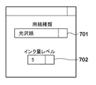
図6は色分解テーブル(LUT)の自動生成を行うアプリケーションのGUIを示す図である。図6を参照して説明すると、ユーザは印刷用紙選択部701より該当の印刷用紙を選択し、最大インク量選択部702より所望の最大インク量レベルを選択する。ここで、印刷用紙とは、例えば、光沢紙A、光沢紙B、光沢紙C等を指し、ユーザが所望の印刷用紙を選択する。所望の最大インク量レベルとは、例えば、レベル1、2、3、4、5などを示し、これらの値は順にインク制限値120%、140%、160%、180%、200%に対応する。
FIG. 6 is a diagram showing a GUI of an application that automatically generates a color separation table (LUT). Referring to FIG. 6, the user selects a corresponding print sheet from the print
ステップS602では、ステップS601において設定された条件に応じてハードディスク(HDD)214のデータ領域から選択された用紙種類に対応する基準LUTと格子点制限値を読み出す。用紙種類に対応する基準LUTとは、例えば、普通紙、アート紙、光沢紙といった用紙種類ごとに予め最適化された基準LUTである。同様に、格子点制限値とは普通紙、アート紙、光沢紙といった用紙種類ごとの格子点毎の制限値である。 In step S602, the reference LUT and the lattice point limit value corresponding to the selected paper type are read from the data area of the hard disk (HDD) 214 according to the conditions set in step S601. The reference LUT corresponding to the paper type is a reference LUT optimized in advance for each paper type such as plain paper, art paper, and glossy paper. Similarly, the grid point limit value is a limit value for each grid point for each paper type such as plain paper, art paper, and glossy paper.
ここで、格子点制限値について具体的に説明する。前述したとおり、光沢性のムラや無駄なインク消費を回避するためには、LUTの各格子点毎にインク制限値を設定する必要がある。そこで、その制限値を印刷種類の各格子点ごとに設定可能な最大値として設定したものが格子点制限値である。 Here, the lattice point limit value will be specifically described. As described above, in order to avoid uneven glossiness and unnecessary ink consumption, it is necessary to set an ink limit value for each grid point of the LUT. Therefore, the grid point limit value is set as the maximum value that can be set for each grid point of the print type.
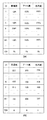
図7は用紙種類に応じたLUTの各格子点の値を示す図であり、図7(a)は各格子点でのインク制限値を表わした表であり、図7(b)は各格子点でのインク信号値を表わした表である。 FIG. 7 is a diagram showing the values of each grid point of the LUT according to the paper type, FIG. 7A is a table showing the ink limit values at each grid point, and FIG. 6 is a table showing ink signal values at points.
各格子点でのインク制限値の具体的な例を示す図7(a)において、IDはLUTの各格子点の番号を示し、この例では、729個の格子点から構成されたLUTを例に挙げ図示している。図7(a)に示すように、全体のインク制限量は別の各格子点ID毎にインク制限値が設定されている。つまり、各格子点においてこのインク制限値以内でLUTを生成することで各格子点において光沢性のムラや無駄なインク消費を抑制することができる。 In FIG. 7A showing a specific example of the ink limit value at each lattice point, ID indicates the number of each lattice point of the LUT. In this example, an LUT composed of 729 lattice points is taken as an example. Are shown in the figure. As shown in FIG. 7A, an ink limit value is set for each grid point ID as the entire ink limit amount. That is, by generating the LUT within the ink limit value at each grid point, uneven glossiness and wasteful ink consumption can be suppressed at each grid point.
また、図7(b)は、図7(a)に示したインク制限値をインク信号値に変換して表わした表である。この実施例では、図7(b)を用いて、後述する格子点ごとのインク量制限処理を実行する。なお、この実施例では、色分解テーブル(LUT)を構成するすべての格子点にインク制限値を設定したが、色分解テーブル(LUT)の1つ以上の格子点にインク制限値を設定する構成であってもよい。また、インク信号値をインク量に変換し、後述する処理を行う構成であってもよい。 FIG. 7B is a table showing the ink limit values shown in FIG. 7A converted into ink signal values. In this embodiment, an ink amount restriction process for each lattice point, which will be described later, is executed using FIG. In this embodiment, the ink limit value is set for all grid points constituting the color separation table (LUT). However, the ink limit value is set for one or more grid points of the color separation table (LUT). It may be. Moreover, the structure which converts an ink signal value into the amount of ink, and performs the process mentioned later may be sufficient.
ステップS603では、基準LUTとステップS601で設定された最大インク量レベルに応じて、最大インク量が増減された仮LUTを作成する。この仮LUTは、指定された最大インク量レベル以内のLUTであり、光沢ムラ回避のための格子点ごとの制限値が考慮されていないLUTである。 In step S603, a temporary LUT in which the maximum ink amount is increased or decreased according to the reference LUT and the maximum ink amount level set in step S601 is created. This temporary LUT is an LUT that is within a specified maximum ink amount level, and does not consider the limit value for each grid point for avoiding gloss unevenness.
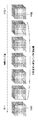
図8は基準LUTから仮LUTを経て値が制限されたLUTを作成する過程の例を示す図である。 FIG. 8 is a diagram illustrating an example of a process of creating an LUT whose value is limited from a reference LUT through a temporary LUT.
具体的な仮LUTの作成方法は次の通りである。即ち、最大インク量base_maxの任意の格子点の基準LUTのシアン、マゼンタ、イエロ、ブラックのインク信号値をそれぞれ、base_ink_c、base_ink_m、base_ink_y、base_ink_kとする。また、その最大インク量レベルのインク量をlevel_inkとする。この場合、仮LUTの任意の格子点の各インク信号値tmp_ink_c、tmp_ink_m、tmp_ink_y、tmp_ink_kは、例えば、以下の式を用いて算出する。 A specific provisional LUT creation method is as follows. That is, the cyan, magenta, yellow, and black ink signal values of the reference LUT at an arbitrary lattice point of the maximum ink amount base_max are set as base_ink_c, base_ink_m, base_ink_y, and base_ink_k, respectively. Further, the ink amount at the maximum ink amount level is assumed to be level_ink. In this case, the ink signal values tmp_ink_c, tmp_ink_m, tmp_ink_y, and tmp_ink_k at arbitrary lattice points of the temporary LUT are calculated using, for example, the following equations.
即ち、
tmp_ink_c = base_ink_c+(level_ink/base_max)*ink_c
tmp_ink_m = base_ink_m+(level_ink/base_max)*ink_m
tmp_ink_y = base_ink_y+(level_ink/base_max)*ink_y
tmp_ink_k = base_ink_k+(level_ink/base_max)*ink_k
である。
That is,
tmp_ink_c = base_ink_c + (level_ink / base_max) * ink_c
tmp_ink_m = base_ink_m + (level_ink / base_max) * ink_m
tmp_ink_y = base_ink_y + (level_ink / base_max) * ink_y
tmp_ink_k = base_ink_k + (level_ink / base_max) * ink_k
It is.
そして、上記式に従って全格子点(この実施例では、729個)における仮LUTのインク信号値を算出する。例えば、この方法に従って最大インク量100%(インク信号値合計255)の基準LUTを基に作成した最大インク量160%(インク信号値合計408)の仮LUTの関係は、例えば、図8(a)に示すような結果となる。図8(a)は、基準LUTの最大インク量が仮LUTの最大インク量よりも少ない場合の例である。また、この方法に従って最大インク量200%(インク信号値合計510)の基準LUTを基に作成した最大インク量160%(インク信号値合計408)の仮LUTの関係は、例えば、図8(b)に示すような結果となる。図8(b)は、基準LUTの最大インク量が仮LUTの最大インク量よりも多い場合の例である。なお、この方法では、比率計算により仮LUTの各インク量を変更したが、例えば、比率計算した結果のインク総量となるように、淡インク量と濃インク量の配分を変更しても良い。 Then, the ink signal values of the temporary LUT are calculated at all grid points (729 in this embodiment) according to the above formula. For example, the relationship of the temporary LUT having the maximum ink amount of 160% (ink signal value total 408) created based on the reference LUT having the maximum ink amount of 100% (ink signal value total 255) according to this method is shown in FIG. ). FIG. 8A shows an example in which the maximum ink amount of the reference LUT is smaller than the maximum ink amount of the temporary LUT. Further, the relationship of the temporary LUT having the maximum ink amount of 160% (ink signal value total 408) created based on the reference LUT having the maximum ink amount of 200% (ink signal value total 510) according to this method is shown in FIG. ). FIG. 8B shows an example in which the maximum ink amount of the reference LUT is larger than the maximum ink amount of the temporary LUT. In this method, each ink amount of the temporary LUT is changed by the ratio calculation. For example, the distribution of the light ink amount and the dark ink amount may be changed so that the total ink amount as a result of the ratio calculation is obtained.
ステップS604は、ステップ603において作成された仮LUTを格子点毎に該当の格子点のインク制限値以下となるようにインク信号値を制限する。 In step S604, the ink signal value is limited so that the temporary LUT created in step 603 is equal to or less than the ink limit value of the corresponding grid point for each grid point.
図9はステップS604における格子点毎のインク量を制限する処理の詳細を示すフローチャートである。 FIG. 9 is a flowchart showing details of the process of limiting the ink amount for each grid point in step S604.
そのフローチャートによれば、まず、ステップS1001では、ハードディスク(HDD)214に記憶された仮LUTと格子点制限値を読み出す。これにより、任意の格子点IDに対応する格子点における仮LUTの各インクのインク信号値とその格子点の格子点制限値が取得できる。 According to the flowchart, first, in step S1001, the temporary LUT and the lattice point limit value stored in the hard disk (HDD) 214 are read. Thereby, the ink signal value of each ink of the temporary LUT at the lattice point corresponding to the arbitrary lattice point ID and the lattice point limit value of the lattice point can be acquired.
次にステップS1002では、該当格子点における仮LUTのインク信号の合計値と格子点制限値とを比較する。ここで、格子点制限値がインク信号の合計値以上の場合、光沢性の低下や無駄なインク消費が発生しないインク信号値(インク量)と判断し、処理はステップS1004に進み、仮LUTの値をそのまま制限後のLUTのインク信号として該当の格子点に格納する。これに対して、仮LUTの信号値の合計値が格子点制限値より大きい場合、光沢の低下や無駄なインク消費が発生する格子点と判断し、処理はステップS1003に進む。そして、ステップS1003では、仮LUTのインク信号値の合計値が格子点制限値以内となるように仮LUTのインク信号値を制限する。その後、処理はステップS1004に進み、制限後のインク信号値を該当の格子点に格納する。 In step S1002, the total value of the temporary LUT ink signals at the corresponding grid point is compared with the grid point limit value. If the grid point limit value is greater than or equal to the total value of the ink signals, it is determined that the ink signal value (ink amount) does not cause a decrease in glossiness or wasteful ink consumption, and the process advances to step S1004 to determine the temporary LUT. The value is stored in the corresponding grid point as the limited LUT ink signal. On the other hand, if the total value of the signal values of the temporary LUT is larger than the lattice point limit value, it is determined as a lattice point where gloss reduction or wasteful ink consumption occurs, and the process proceeds to step S1003. In step S1003, the ink signal value of the temporary LUT is limited so that the total value of the ink signal values of the temporary LUT is within the lattice point limit value. Thereafter, the process proceeds to step S1004, and the restricted ink signal value is stored in the corresponding grid point.
ここで実行するインク量制限処理では、例えば、仮LUTのインク信号値の合計と格子点制限値の差分とその格子点を構成するインク種類とその割合を用いて制限する。 In the ink amount restriction process executed here, the restriction is performed using, for example, the difference between the sum of the ink signal values of the temporary LUT and the lattice point restriction value, the type of ink constituting the lattice point, and the ratio thereof.
ここで、任意の格子点の仮LUTのシアン、マゼンタ、イエロ、ブラックのインク信号値を夫々、tmp_ink_c、tmp_ink_m、tmp_ink_y、tmp_ink_kとする。また、そのインク信号値をtmp_ink_sum、格子点制限値をLim_inkとする。この場合、格子点のインク制限後の各インク信号値rest_ink_c、rest_ink_m、rest_ink_y、rest_ink_kは、以下の式を用いて制限する。即ち、
rest_ink_c=tmp_ink_c+{(Lim_ink−tmp_ink_Sum)/(tmp_ink_Sum)}*tmp_ink_c
rest_ink_m=tmp_ink_m+{(Lim_ink−tmp_ink_Sum)/(tmp_ink_Sum)}*tmp_ink_m
rest_ink_y=tmp_ink_y+{(Lim_ink−tmp_ink_Sum)/(tmp_ink_Sum)}*tmp_ink_y
rest_ink_k=tmp_ink_k+{(Lim_ink−tmp_ink_Sum)/(tmp_ink_Sum)}*tmp_ink_k
である。
Here, the cyan, magenta, yellow, and black ink signal values of the temporary LUT at an arbitrary lattice point are set to tmp_ink_c, tmp_ink_m, tmp_ink_y, and tmp_ink_k, respectively. Further, the ink signal value is tmp_ink_sum, and the lattice point limit value is Lim_ink. In this case, each ink signal value rest_ink_c, rest_ink_m, rest_ink_y, rest_ink_k after the ink restriction of the grid points is restricted using the following expression. That is,
rest_ink_c = tmp_ink_c + {(Lim_ink-tmp_ink_Sum) / (tmp_ink_Sum)} * tmp_ink_c
rest_ink_m = tmp_ink_m + {(Lim_ink-tmp_ink_Sum) / (tmp_ink_Sum)} * tmp_ink_m
rest_ink_y = tmp_ink_y + {(Lim_ink-tmp_ink_Sum) / (tmp_ink_Sum)} * tmp_ink_y
rest_ink_k = tmp_ink_k + {(Lim_ink-tmp_ink_Sum) / (tmp_ink_Sum)} * tmp_ink_k
It is.
また、格子点制限値が仮LUTの格子点のインク信号値の合計値以上の場合、仮LUTのインク信号値の合計値を制限値格子点の制限値まで増加させてもよい。つまり、画質に影響がない限界までインク量を増加させ発色を向上させることができる。この場合でも、上記の計算式を用いて各インク量を算出することができる。 When the grid point limit value is equal to or greater than the total value of the ink signal values of the temporary LUT grid points, the total value of the temporary LUT ink signal values may be increased to the limit value of the limit grid points. That is, the amount of ink can be increased to the limit that does not affect the image quality, and color development can be improved. Even in this case, each ink amount can be calculated using the above-described calculation formula.
そして、ステップS1105では、LUTを構成する全格子点(この実施例では、729個)に関する処理が終了したかどうかを調べ、処理続行と判断するなら、処理はステップS1001に戻り、そうでなければ処理は終了する。 In step S1105, it is checked whether or not the processing for all grid points constituting the LUT (729 in this embodiment) has been completed. If it is determined that the processing is to be continued, the processing returns to step S1001, otherwise. The process ends.
図8(c)と図8(d)は、ステップS601による生成条件の選択にて光沢紙Cを選択した場合の光沢紙Cの制限処理を適用した際に仮LUTに対して値を制限後のLUTの例を示す図である。図8(c)は図8(a)に示した仮LUTのインク量を制限した結果を示しており、図8(d)は図8(b)に示した仮LUTのインク量を制御した結果を示している。 FIG. 8C and FIG. 8D show values after limiting the value for the temporary LUT when applying the glossy paper C restriction process when the glossy paper C is selected in the selection of the generation condition in step S601. It is a figure which shows the example of LUT. FIG. 8C shows the result of limiting the ink amount of the temporary LUT shown in FIG. 8A, and FIG. 8D shows the ink amount of the temporary LUT shown in FIG. 8B controlled. Results are shown.
従って以上説明した実施例に従えば、各格子点のインク量の値を制限したLUTを適用することで、ユーザが所望の最大インク量以内のLUTを自動生成ができる。このようにして、各インク信号値に対応した格子点毎にインク量が制限されるので、記録画像に光沢ムラの発生することが防止され、さらには無駄なインク消費を防止することができる。 Therefore, according to the embodiment described above, the LUT within the maximum ink amount desired by the user can be automatically generated by applying the LUT in which the ink amount value at each grid point is limited. In this way, since the ink amount is limited for each grid point corresponding to each ink signal value, it is possible to prevent the occurrence of uneven glossiness in the recorded image and further to prevent wasteful ink consumption.
この実施例では、格子点制限値の代わりに基準LUTとは異なる制限インク量の基準LUTを保持するようにし、2つのLUTを用いて、格子点毎に制限値以内のインク信号値となるように色分解テーブル自動生成処理を実行する例について説明する。なお、ここでは、この実施例に特徴的な部分のみを説明し、実施例1で既に説明したのと共通の部分についてその説明を省略する。 In this embodiment, instead of the grid point limit value, a reference LUT having a limited ink amount different from the reference LUT is held, and two LUTs are used so that the ink signal value is within the limit value for each grid point. Next, an example of executing the color separation table automatic generation process will be described. Here, only the characteristic part of this embodiment will be described, and the description of the parts common to those already described in the first embodiment will be omitted.
図10は自動生成可能な制限インク値の範囲と2つの基準LUTとの関係を示す図である。この実施例では、図10に示すように、自動生成可能な制限インク量の範囲に対し、その両端である最大インク量が上限となるLUT(以下、上位LUT)1101と最大インク量が下限となるLUT(以下、下位LUT)1102とを予め作成する。ここで、上位LUT1101は、最大インク量が最も多い場合に、格子点毎のインク信号値が最適化され、光沢性にムラや無駄なインク消費が発生しないLUTである。従って、上位LUTの各格子点のインク信号値は、格子点毎のインク制限値と同値となる。
FIG. 10 is a diagram showing the relationship between the range of limit ink values that can be automatically generated and two reference LUTs. In this embodiment, as shown in FIG. 10, with respect to the range of the limited ink amount that can be automatically generated, the maximum ink amount at both ends of the range is an LUT (hereinafter referred to as upper LUT) 1101 and the maximum ink amount is the lower limit. LUT (hereinafter referred to as “lower LUT”) 1102 is created in advance. Here, the
以上を踏まえ、フローチャートを参照し、実施例2に従う色分解テーブル(LUT)自動生成処理について説明する。 Based on the above, the color separation table (LUT) automatic generation processing according to the second embodiment will be described with reference to a flowchart.
図11は実施例2に従うLUT自動生成処理を示すフローチャートである。 FIG. 11 is a flowchart showing LUT automatic generation processing according to the second embodiment.
ステップS1201では、実施例1におけるステップS601と同様に自動生成に関する生成条件を入力する。次にステップS1202では、ステップS1201において設定された条件に応じて、ハードディスク(HDD)214のデータ領域から該当の用紙種類に対応する2つのLUTを読み込む。ここでは、例えば、普通紙、アート紙、光沢紙といった用紙種類毎に予め最適化された2つの基準LUTとして上位LUTと下位LUTとを読み出す。 In step S1201, generation conditions related to automatic generation are input as in step S601 in the first embodiment. Next, in step S1202, two LUTs corresponding to the corresponding paper type are read from the data area of the hard disk (HDD) 214 in accordance with the conditions set in step S1201. Here, for example, the upper LUT and the lower LUT are read as two reference LUTs optimized in advance for each paper type such as plain paper, art paper, and glossy paper.
さらにステップS1203では、実施例1のステップS603で説明したのと同様の方法で、仮LUTを作成する。ただし、この仮LUT生成において使用する基準LUTは実施例1とは異なり、上位LUTと下位LUTの2つの基準LUTのうちのいずれかを選択し使用することができる。 In step S1203, a temporary LUT is created by the same method as described in step S603 of the first embodiment. However, unlike the first embodiment, the reference LUT used in the provisional LUT generation can select and use one of the two reference LUTs, the upper LUT and the lower LUT.
基準LUTの使い分けは、例えば、ステップS1201で選択設定した最大インク量レベルに応じて使い分ける。具体的には、選択されたインク制限レベルが比較的大きい場合は、上位LUTを使用し、選択されたインク制限レベルが比較的小さい場合は、下位LUTを使用する。 For example, the reference LUT is selectively used according to the maximum ink amount level selected and set in step S1201. Specifically, when the selected ink restriction level is relatively large, the upper LUT is used, and when the selected ink restriction level is relatively small, the lower LUT is used.
また別の選択方法として、2つの基準LUTを加重平均して、新たに基準LUTを生成し、その生成した基準LUTを用いて仮LUTを用いても良い。一般的に最大インク量が異なる複数のLUTを作成する場合、最大インク量が多いLUTと少ないLUTとではLUTで使用するインクの組み合わせやインク量の割合は異なる。最大インク量が多いLUTは、インク制限量に余裕があるため4色のインクを用いる記録装置であれば、CインクとMインクとYインクとを組み合わせたプロセスグレイ使用し、粒状性の向上を図る。また、淡インクを使用する記録装置であれば、淡インクを多く使用することで、粒状性等の向上を図る。一方、最大インク量が少ないLUTは、インク制限量に余裕がないためプロセスグレイ、淡インクを使用すると発色性が十分に確保できない。従って、プロセスグレイ、淡インクの使用量を抑えるようにする。 As another selection method, two reference LUTs may be weighted and averaged to newly generate a reference LUT, and a temporary LUT may be used by using the generated reference LUT. In general, when a plurality of LUTs having different maximum ink amounts are created, the combination of inks used in the LUT and the ratio of the ink amount are different between the LUT having a large maximum ink amount and the LUT having a small maximum ink amount. LUTs with a large maximum ink amount have a sufficient amount of ink limit, so if the recording device uses four colors of ink, use process gray that combines C ink, M ink, and Y ink to improve graininess. Plan. In the case of a recording apparatus that uses light ink, the graininess and the like are improved by using a large amount of light ink. On the other hand, a LUT with a small maximum ink amount does not have a sufficient amount of ink limit, so that color development cannot be sufficiently secured when process gray or light ink is used. Therefore, the use amount of process gray and light ink is suppressed.
以上のように、選択された最大インク量レベルに応じて基準LUTを切り替え、最大インク量レベルに応じてより最適なLUTを作成することができる。 As described above, it is possible to switch the reference LUT according to the selected maximum ink amount level and create a more optimal LUT according to the maximum ink amount level.
ステップS1204では、ステップS1203において作成された仮LUTの値を格子点毎に該当の格子点の格子点制限値以下となるようにインク量を制限する。 In step S1204, the ink amount is limited so that the value of the temporary LUT created in step S1203 is equal to or less than the lattice point limit value of the corresponding lattice point for each lattice point.
図12はステップS1204における格子点毎のインク量を制限する処理の詳細を示すフローチャートである。図12と図9とを比較すると分かるように、実施例2と実施例1との違いは、実施例1で用いた格子点制限値の代わりに上位LUTの各格子点のインク信号を制限値として使用する点にある。前述したように、上位LUTの各格子点のインク信号の合計値は格子点制限値と同値であるため、代用可能となるのである。 FIG. 12 is a flowchart showing details of the process of limiting the ink amount for each grid point in step S1204. As can be seen from a comparison between FIG. 12 and FIG. 9, the difference between the second embodiment and the first embodiment is that the ink signal of each grid point of the upper LUT is replaced by the limit value instead of the grid point limit value used in the first embodiment. It is in point to use as. As described above, since the total value of the ink signals at each grid point of the upper LUT is the same value as the grid point limit value, it can be substituted.
そのフローチャートによれば、ステップS1301では、ハードディスク(HDD)214に記憶された仮LUTと上位LUTを読み出す。これにより、任意の格子点IDに対応する格子点における仮LUTの各インクのインク量とその格子点の上位LUTの各インクのインク信号値とを取得する。 According to the flowchart, in step S1301, the temporary LUT and the upper LUT stored in the hard disk (HDD) 214 are read. Thereby, the ink amount of each ink in the temporary LUT at the lattice point corresponding to the arbitrary lattice point ID and the ink signal value of each ink in the upper LUT of the lattice point are acquired.
次に、ステップS1302では該当格子点における仮LUTのインク信号値の合計と上位LUTのインク信号値の合計とを比較する。ここで、上位LUTのインク信号値の合計値が仮LUTのインク信号値の合計値以上である場合は、光沢性の低下が発生しないインク量と判断し、処理はステップS1304に進む。そして、ステップS1304では、仮LUTのインク信号値をそのまま、制限後のLUTのインク信号値として該当の格子点に格納する。 In step S1302, the sum of the ink signal values of the temporary LUT at the corresponding grid point is compared with the sum of the ink signal values of the upper LUT. Here, when the total value of the ink signal values of the upper LUT is equal to or larger than the total value of the ink signal values of the temporary LUT, it is determined that the ink amount does not cause a decrease in glossiness, and the process proceeds to step S1304. In step S1304, the ink signal value of the temporary LUT is stored as it is at the corresponding grid point as the ink signal value of the limited LUT.
これに対して、仮LUTのインク信号値の合計値が上位LUTのインク信号値の合計値より大きい場合は、光沢の低下が発生する格子点と判断し、処理はステップS1303に進む。ステップS1303では、上位LUTのインク信号値の合計以内となるように仮LUTのインク信号値を制限する。そして、ステップS1304では、制限後のインク信号値を該当の格子点に格納する。 On the other hand, when the total value of the ink signal values of the temporary LUT is larger than the total value of the ink signal values of the upper LUT, it is determined as a lattice point where gloss reduction occurs, and the process proceeds to step S1303. In step S1303, the ink signal value of the temporary LUT is limited to be within the total of the ink signal values of the upper LUT. In step S1304, the restricted ink signal value is stored in the corresponding grid point.
ここで実行するインク量制限処理では、例えば、仮LUTの総インク量と上位LUTの総インク量との間の差分とその格子点を構成するインク種類とその割合とを用いて制限する。 In the ink amount restriction process executed here, the restriction is performed using, for example, the difference between the total ink amount of the temporary LUT and the total ink amount of the upper LUT, the ink types constituting the lattice points, and the ratio thereof.
具体的には、任意の格子点の仮LUTのシアン、マゼンタ、イエロ、ブラックのインク信号値をそれぞれ、tmp_ink_c、tmp_ink_m、tmp_ink_y、tmp_ink_kとする。また、その合計値をtmp_ink_sum、また上位LUTの該当格子点のインク信号値をmax_ink_sumとする。その場合、インク制限後の各格子点の各インク信号値rest_ink_c、rest_ink_m、rest_ink_y、rest_ink_kは、以下の式を用いて制限する。 Specifically, cyan, magenta, yellow, and black ink signal values of a temporary LUT at an arbitrary grid point are set to tmp_ink_c, tmp_ink_m, tmp_ink_y, and tmp_ink_k, respectively. The total value is tmp_ink_sum, and the ink signal value of the corresponding grid point of the upper LUT is max_ink_sum. In that case, each ink signal value rest_ink_c, rest_ink_m, rest_ink_y, rest_ink_k at each grid point after ink restriction is restricted using the following equation.
即ち、
rest_ink_c=tmp_ink_c+{(max_ink_Sum−tmp_ink_sum)/tmp_ink_sum}*tmp_ink_c
rest_ink_m=tmp_ink_m+{(max_ink_Sum−tmp_ink_sum)/tmp_ink_sum}*tmp_ink_m
rest_ink_y=tmp_ink_y+{(max_ink_Sum−tmp_ink_sum)/tmp_ink_sum}*tmp_ink_y
rest_ink_k=tmp_ink_k+{(max_ink_Sum−tmp_ink_sum)/tmp_ink_sum}*tmp_ink_k
である。
That is,
rest_ink_c = tmp_ink_c + {(max_ink_Sum-tmp_ink_sum) / tmp_ink_sum} * tmp_ink_c
rest_ink_m = tmp_ink_m + {(max_ink_Sum-tmp_ink_sum) / tmp_ink_sum} * tmp_ink_m
rest_ink_y = tmp_ink_y + {(max_ink_Sum−tmp_ink_sum) / tmp_ink_sum} * tmp_ink_y
rest_ink_k = tmp_ink_k + {(max_ink_Sum−tmp_ink_sum) / tmp_ink_sum} * tmp_ink_k
It is.
そして、ステップS1305では、LUTを構成する全格子点(この実施例では、729個)に関する処理が終了したかどうかを調べ、処理続行と判断するなら、処理はステップS1301に戻り、そうでなければ処理は終了する。 In step S1305, it is checked whether or not the processing for all grid points (729 in this embodiment) constituting the LUT has been completed. If it is determined that the processing is to be continued, the processing returns to step S1301, otherwise. The process ends.
従って以上説明した実施例によれば、2つの基準LUTを保持し、格子点毎にインク信号値を制御することができる。2つの基準LUTを保持し、ユーザが指定したインク制限レベルに応じて、基準LUTを使い分けることでより最適なLUTを自動生成することができる。さらに、基準LUTのインク信号値の合計を格子点制限値の代わりとし、格子点毎に最適なインク制限値に設定することができる。 Therefore, according to the embodiment described above, it is possible to hold two reference LUTs and control the ink signal value for each lattice point. It is possible to automatically generate a more optimal LUT by holding two reference LUTs and using different reference LUTs according to the ink restriction level designated by the user. Further, the sum of the ink signal values of the reference LUT can be set as an optimal ink limit value for each grid point, instead of the grid point limit value.
なお、本発明は上述の実施形態の1以上の機能を実現するプログラムをネットワーク又は記憶媒体を介してシステム又は装置に供給し、そのシステム又は装置のコンピュータにおける1つ以上のプロセッサがプログラムを読出し実行する処理でも実現可能である。また、1以上の機能を実現する回路(例えば、ASIC)によっても実現可能である。 The present invention supplies a program that realizes one or more functions of the above-described embodiments to a system or apparatus via a network or a storage medium, and one or more processors in a computer of the system or apparatus read and execute the program This process can be realized. It can also be realized by a circuit (for example, ASIC) that realizes one or more functions.
101 LUT、102 格子点、201 ホスト装置、202 アプリケーション、
203 カラーマッチング処理、204 インク分解処理、205 ハーフトーン処理、
206 ドライバ、207 テーブル保持部、208 記録装置、209 画像処理部、
210 記録処理部、211 CPU、212 RAM、213 ROM、
214 HDD、215 システムバス、216 インタフェース(I/F)、
217 ビデオカード、218 ディスプレイ、
401 記録媒体、402 記録ヘッド、403 ノズル、
501 光沢ムラ発生時の光沢性、502 光沢ムラ発生時のインク総量、
503 光沢ムラが発生しない場合の光沢性、
504 光沢ムラが発生しない場合のインク総量、
701 用紙種類選択部、702 インク量レベル選択部
101 LUT, 102 grid points, 201 host device, 202 application,
203 Color matching processing, 204 Ink separation processing, 205 Halftone processing,
206 driver, 207 table holding unit, 208 recording device, 209 image processing unit,
210 Recording processing unit, 211 CPU, 212 RAM, 213 ROM,
214 HDD, 215 system bus, 216 interface (I / F),
217 video card, 218 display,
401 recording medium, 402 recording head, 403 nozzle,
501 Glossiness when gloss unevenness occurs, 502 Total amount of ink when gloss unevenness occurs,
503 Glossiness when gloss unevenness does not occur,
504 Total amount of ink when gloss unevenness does not occur,
701 Paper type selection unit, 702 Ink amount level selection unit
Claims (14)
前記記録媒体の種類に応じた基準のルックアップテーブルと前記作成されるルックアップテーブルの各格子点に設定可能な制限値とを保持する保持手段と、
用いる記録媒体の種類と最大の記録剤量とを設定する設定手段と、
前記保持手段に保持された基準のルックアップテーブルと前記設定手段によって設定された記録媒体の種類と最大の記録剤量とに基づいて仮のルックアップテーブルを作成する作成手段と、
前記作成手段により作成された仮のルックアップテーブルの各格子点の値と前記各格子点に設定可能な制限値とを比較する比較手段と、
前記比較手段による比較の結果に基づいて、各格子点の値が前記各格子点に設定可能な制限値以下となるようにルックアップテーブルを生成する生成手段と、
前記生成手段により生成されたルックアップテーブルを用いて前記入力された画像データを変換する変換手段とを有することを特徴とする画像処理装置。 An image processing apparatus that creates a three-dimensional lookup table corresponding to a recording medium to be used and a recording agent amount to be used for recording on the recording medium, and converts input image data using the created lookup table There,
Holding means for holding a reference lookup table according to the type of the recording medium and limit values that can be set at each grid point of the created lookup table;
Setting means for setting the type of recording medium to be used and the maximum amount of recording agent;
Creating means for creating a temporary look-up table based on the reference look-up table held in the holding means, the type of recording medium set by the setting means and the maximum amount of recording agent;
A comparison means for comparing the value of each grid point of the temporary lookup table created by the creation means with a limit value that can be set for each grid point;
Generating means for generating a lookup table based on the result of comparison by the comparison means so that the value of each grid point is less than or equal to a limit value that can be set for each grid point;
An image processing apparatus comprising: conversion means for converting the input image data using the lookup table generated by the generation means.
前記記録媒体の種類には、普通紙、アート紙、光沢紙を含むことを特徴とする請求項1に記載の画像処理装置。 The lookup table is a color separation lookup table;
The image processing apparatus according to claim 1, wherein the types of the recording medium include plain paper, art paper, and glossy paper.
前記作成手段は、前記設定手段によって設定された最大の記録剤量に応じて、前記第1の基準のルックアップテーブルと前記第2の基準のルックアップテーブルとの少なくともいずれかを用いて前記仮のルックアップテーブルを作成することを特徴とする請求項1乃至3のいずれか1項に記載の画像処理装置。 The holding means uses the first reference lookup table as the upper limit of the recording agent amount limit range and the second reference as the lower limit of the recording agent amount limit range as the reference lookup table. With a look-up table and
The creation means uses the temporary reference table of at least one of the first reference lookup table and the second reference lookup table according to the maximum recording agent amount set by the setting means. The image processing apparatus according to claim 1, wherein a lookup table is created.
前記記録剤量はインク量であることを特徴とする請求項10に記載の画像処理装置。 The recording apparatus includes a recording head that performs recording in accordance with an inkjet method,
The image processing apparatus according to claim 10, wherein the recording agent amount is an ink amount.
前記記録媒体の種類に応じた基準のルックアップテーブルと前記作成されるルックアップテーブルの各格子点に設定可能な制限値とを保持する保持工程と、
用いる記録媒体の種類と最大の記録剤量とを設定する設定工程と、
前記保持工程において保持された基準のルックアップテーブルと前記設定工程において設定された記録媒体の種類と最大の記録剤量とに基づいて仮のルックアップテーブルを作成する作成工程と、
前記作成工程において作成された仮のルックアップテーブルの各格子点の値と前記各格子点に設定可能な制限値とを比較する比較工程と、
前記比較工程における比較の結果に基づいて、各格子点の値が前記各格子点に設定可能な制限値以下となるようにルックアップテーブルを生成する生成工程と、
前記生成工程において生成されたルックアップテーブルを用いて前記入力された画像データを変換する変換工程とを有することを特徴とする画像処理方法。 An image processing apparatus for creating a three-dimensional lookup table corresponding to a recording medium to be used and a recording agent amount used for recording on the recording medium, and converting input image data using the created lookup table An image processing method comprising:
A holding step for holding a reference lookup table according to the type of the recording medium and a limit value that can be set for each grid point of the created lookup table;
A setting step for setting the type of recording medium to be used and the maximum amount of recording agent;
A creation step of creating a temporary lookup table based on the reference lookup table held in the holding step, the type of the recording medium set in the setting step and the maximum recording agent amount;
A comparison step of comparing a value of each grid point of the temporary lookup table created in the creation step with a limit value that can be set for each grid point;
Based on the result of the comparison in the comparison step, a generation step for generating a lookup table so that the value of each grid point is equal to or less than a limit value that can be set for each grid point;
A conversion step of converting the input image data using the lookup table generated in the generation step.
Priority Applications (2)
| Application Number | Priority Date | Filing Date | Title |
|---|---|---|---|
| JP2014226402A JP6417191B2 (en) | 2014-11-06 | 2014-11-06 | Image processing apparatus and image processing method |
| US14/925,918 US9406004B2 (en) | 2014-11-06 | 2015-10-28 | Image processing apparatus, image processing method, and storage medium |
Applications Claiming Priority (1)
| Application Number | Priority Date | Filing Date | Title |
|---|---|---|---|
| JP2014226402A JP6417191B2 (en) | 2014-11-06 | 2014-11-06 | Image processing apparatus and image processing method |
Publications (3)
| Publication Number | Publication Date |
|---|---|
| JP2016092650A JP2016092650A (en) | 2016-05-23 |
| JP2016092650A5 JP2016092650A5 (en) | 2017-11-02 |
| JP6417191B2 true JP6417191B2 (en) | 2018-10-31 |
Family
ID=55912449
Family Applications (1)
| Application Number | Title | Priority Date | Filing Date |
|---|---|---|---|
| JP2014226402A Active JP6417191B2 (en) | 2014-11-06 | 2014-11-06 | Image processing apparatus and image processing method |
Country Status (2)
| Country | Link |
|---|---|
| US (1) | US9406004B2 (en) |
| JP (1) | JP6417191B2 (en) |
Families Citing this family (5)
| Publication number | Priority date | Publication date | Assignee | Title |
|---|---|---|---|---|
| JP6812186B2 (en) | 2016-09-29 | 2021-01-13 | キヤノン株式会社 | Image processing equipment, image processing methods and programs |
| JP2019043109A (en) * | 2017-09-07 | 2019-03-22 | 株式会社Screenホールディングス | Ink limit amount calculation method and ink limit amount calculation program |
| US10713940B2 (en) | 2017-10-31 | 2020-07-14 | Waymo Llc | Detecting and responding to traffic redirection for autonomous vehicles |
| US10401862B2 (en) * | 2017-10-31 | 2019-09-03 | Waymo Llc | Semantic object clustering for autonomous vehicle decision making |
| JP7433918B2 (en) | 2020-01-09 | 2024-02-20 | キヤノン株式会社 | Image processing device and image processing method |
Family Cites Families (8)
| Publication number | Priority date | Publication date | Assignee | Title |
|---|---|---|---|---|
| JP2005028689A (en) * | 2003-07-10 | 2005-02-03 | Seiko Epson Corp | Printing system, printing system control program, printing system control method, printing data generating device, printing data generation program, printing data generation method, printing device, printing device control program, and printing method |
| JP2007088636A (en) * | 2005-09-20 | 2007-04-05 | Canon Inc | Color separation table generating method and image processing apparatus |
| JP4408915B2 (en) * | 2006-08-08 | 2010-02-03 | キヤノン株式会社 | Profile creation method, profile creation program, and printer |
| JP2010098527A (en) * | 2008-10-16 | 2010-04-30 | Seiko Epson Corp | Method of creating look-up table, and printing apparatus |
| JP2010232975A (en) | 2009-03-27 | 2010-10-14 | Seiko Epson Corp | Color conversion table creation method, printer with color conversion table created by the color conversion table creation method, color conversion table created by color conversion table creation method, and printer |
| JP5333389B2 (en) * | 2010-09-10 | 2013-11-06 | ブラザー工業株式会社 | Image processing apparatus and image processing program |
| JP5848190B2 (en) * | 2012-05-10 | 2016-01-27 | 富士フイルム株式会社 | Profile creation apparatus and method, color conversion apparatus and method, program, and printing system |
| US9106875B2 (en) * | 2012-10-04 | 2015-08-11 | Kyocera Document Solutions Inc. | System and method for creating a run-time color-conversion look-up table |
-
2014
- 2014-11-06 JP JP2014226402A patent/JP6417191B2/en active Active
-
2015
- 2015-10-28 US US14/925,918 patent/US9406004B2/en active Active
Also Published As
| Publication number | Publication date |
|---|---|
| US9406004B2 (en) | 2016-08-02 |
| JP2016092650A (en) | 2016-05-23 |
| US20160132757A1 (en) | 2016-05-12 |
Similar Documents
| Publication | Publication Date | Title |
|---|---|---|
| US11077674B2 (en) | Dual pass uniformity printing compensation mechanism | |
| US7360869B2 (en) | Image processing and ink-jet recording apparatus for carrying out processing for reducing amount of ink delivered from recording apparatus to recording medium | |
| JP6587552B2 (en) | Image processing apparatus and image processing method | |
| JP6417191B2 (en) | Image processing apparatus and image processing method | |
| JP2008074103A (en) | Printer and printing method | |
| JP5062103B2 (en) | Image processing apparatus, image processing method, and image processing program | |
| JP2019062287A (en) | Generation device and computer program | |
| JP2023052888A (en) | Image processing device, image processing method, and program | |
| JP4240210B2 (en) | Print control apparatus, print control method, and print control program | |
| JP2011025658A (en) | Image forming apparatus and method | |
| JP4003046B2 (en) | PRINT CONTROL DEVICE, PRINT CONTROL METHOD, PRINT SYSTEM, PRINT CONTROL PROGRAM, AND MEDIUM CONTAINING PRINT CONTROL PROGRAM | |
| JP4078264B2 (en) | Image processing apparatus and method | |
| US10511744B2 (en) | Image processing apparatus and method that suppress difference in colors printed in forward and backward scans, and storage medium | |
| JP2023052886A (en) | Image processing device, image processing method, and program | |
| JP2020187665A (en) | Color conversion method, color conversion device, and program | |
| US11392807B2 (en) | Image processing apparatus, image processing method, and storage medium | |
| JP5284138B2 (en) | Image processing apparatus and image processing method | |
| JP5595341B2 (en) | Image processing apparatus, image processing method, and recording apparatus | |
| JP4433140B2 (en) | Print control apparatus, print control method, print control program, color conversion table, and ink amount determination method | |
| JP7362365B2 (en) | Image processing device, image processing method and program | |
| JP2006281445A (en) | Printing data forming apparatus and printing data formation program | |
| JP4273318B2 (en) | Color conversion apparatus, color conversion method, and print control program | |
| JP4407096B2 (en) | Color image output device | |
| JP2006159648A (en) | Recording system, image processor, inkjet recorder and image processing method | |
| KR100662211B1 (en) | Method for controlling raster image processing of large format printer |
Legal Events
| Date | Code | Title | Description |
|---|---|---|---|
| A521 | Written amendment |
Free format text: JAPANESE INTERMEDIATE CODE: A523 Effective date: 20170920 |
|
| A621 | Written request for application examination |
Free format text: JAPANESE INTERMEDIATE CODE: A621 Effective date: 20170920 |
|
| A977 | Report on retrieval |
Free format text: JAPANESE INTERMEDIATE CODE: A971007 Effective date: 20180514 |
|
| A131 | Notification of reasons for refusal |
Free format text: JAPANESE INTERMEDIATE CODE: A131 Effective date: 20180518 |
|
| A521 | Written amendment |
Free format text: JAPANESE INTERMEDIATE CODE: A523 Effective date: 20180705 |
|
| A131 | Notification of reasons for refusal |
Free format text: JAPANESE INTERMEDIATE CODE: A131 Effective date: 20180727 |
|
| A521 | Written amendment |
Free format text: JAPANESE INTERMEDIATE CODE: A523 Effective date: 20180829 |
|
| TRDD | Decision of grant or rejection written | ||
| A01 | Written decision to grant a patent or to grant a registration (utility model) |
Free format text: JAPANESE INTERMEDIATE CODE: A01 Effective date: 20180907 |
|
| A61 | First payment of annual fees (during grant procedure) |
Free format text: JAPANESE INTERMEDIATE CODE: A61 Effective date: 20181005 |
|
| R151 | Written notification of patent or utility model registration |
Ref document number: 6417191 Country of ref document: JP Free format text: JAPANESE INTERMEDIATE CODE: R151 |