WO2012132343A1 - Information processing apparatus and information processing method, recording medium, and program - Google Patents
Information processing apparatus and information processing method, recording medium, and program Download PDFInfo
- Publication number
- WO2012132343A1 WO2012132343A1 PCT/JP2012/001977 JP2012001977W WO2012132343A1 WO 2012132343 A1 WO2012132343 A1 WO 2012132343A1 JP 2012001977 W JP2012001977 W JP 2012001977W WO 2012132343 A1 WO2012132343 A1 WO 2012132343A1
- Authority
- WO
- WIPO (PCT)
- Prior art keywords
- touch
- information
- identifying
- positions
- touch panel
- Prior art date
Links
Images


Classifications
-
- G—PHYSICS
- G06—COMPUTING OR CALCULATING; COUNTING
- G06F—ELECTRIC DIGITAL DATA PROCESSING
- G06F3/00—Input arrangements for transferring data to be processed into a form capable of being handled by the computer; Output arrangements for transferring data from processing unit to output unit, e.g. interface arrangements
- G06F3/01—Input arrangements or combined input and output arrangements for interaction between user and computer
- G06F3/03—Arrangements for converting the position or the displacement of a member into a coded form
- G06F3/041—Digitisers, e.g. for touch screens or touch pads, characterised by the transducing means
- G06F3/0416—Control or interface arrangements specially adapted for digitisers
- G06F3/04166—Details of scanning methods, e.g. sampling time, grouping of sub areas or time sharing with display driving
-
- G—PHYSICS
- G06—COMPUTING OR CALCULATING; COUNTING
- G06F—ELECTRIC DIGITAL DATA PROCESSING
- G06F3/00—Input arrangements for transferring data to be processed into a form capable of being handled by the computer; Output arrangements for transferring data from processing unit to output unit, e.g. interface arrangements
- G06F3/01—Input arrangements or combined input and output arrangements for interaction between user and computer
- G06F3/03—Arrangements for converting the position or the displacement of a member into a coded form
- G06F3/041—Digitisers, e.g. for touch screens or touch pads, characterised by the transducing means
Definitions
- the present disclosure relates to an information processing apparatus and an information processing method, a recording medium, and a program, and more specifically relates to an information processing apparatus and an information processing method, a recording medium, and a program, which make it possible to execute processing reliably.
- Patent Document 1 describes that whether or not to execute an operation by multi-touch on a multi-touch display is determined on the basis of whether a multi-touch flag is set or unset.
- Patent Document 1 there is a risk that the user may not be able to execute desired processing in a case where a plurality of multi-touch displays are handled as a single multi-touch display.
- the present disclosure has been made in view of the above circumstances, and makes it possible to execute processing reliably.
- the invention provides a method for identifying a subset of touch positions.
- the method comprises receiving, from a first touch input device, first touch information comprising first positional information identifying one or more first device positions touched by a user; receiving, from a second touch input device, second touch information comprising second positional information identifying one or more second device positions touched by the user; identifying, based on the first and second touch information, a subset of the first and second device positions as detected positions; and sending detection information identifying the detected positions to an application.
- the invention provides an apparatus for providing a user interface, comprising a hardware processor and a memory coupled to the processor and containing instructions.
- the instructions when executed by the processor, cause the apparatus to receive, from a first touch input device, first touch information comprising first positional information identifying one or more first device positions touched by a user; receive, from a second touch input device, second touch information comprising second positional information identifying one or more second device positions touched by the user; identify, based on the first and second touch information, a subset of the first and second device positions as detected positions; and send detection information identifying the detected positions to an application.
- the invention provides a non-transitory, computer-readable medium storing instructions which, when executed by a processor, cause a user interface to perform a method.
- the method comprises receiving, from a first touch input device, first touch information comprising first positional information identifying one or more first device positions touched by a user; receiving, from a second touch input device, second touch information comprising second positional information identifying one or more second device positions touched by the user; identifying, based on the first and second touch information, a subset of the first and second device positions as detected positions; and sending detection information identifying the detected positions to an application.
- Fig. 1 is a diagram showing an example of input of a touch panel to which the present disclosure is not applied.
- Fig. 2 is a diagram showing an example of input of a touch panel to which the present disclosure is not applied.
- Fig. 3 is a diagram showing an example of input of a touch panel to which the present disclosure is not applied.
- Fig. 4 is a block diagram showing an example of the hardware configuration of a personal computer to which the present disclosure is applied.
- Fig. 5 is a block diagram showing an example of the functional configuration of a CPU.
- Fig. 6 is a diagram showing an overview of processing by software.
- Fig. 7 is a diagram showing an example of input of a touch panel.
- Fig. 8 is a diagram showing an example of output of a touch panel.
- Fig. 1 is a diagram showing an example of input of a touch panel to which the present disclosure is not applied.
- Fig. 2 is a diagram showing an example of input of a touch panel to which the present disclosure is
- FIG. 9 is a flowchart illustrating a touch information selection process.
- Fig. 10 is a diagram showing an example of input and output of a touch panel.
- Fig. 11 is a diagram showing an example of input of a touch panel.
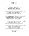
- Fig. 12 is a flowchart illustrating an upper-side rearrangement process.
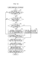
- Fig. 13 is a flowchart illustrating an upper-side selection process.
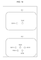
- Fig. 14 is a diagram showing an example of output of a touch panel.
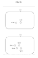
- Fig. 15 is a diagram showing an example of input of a touch panel.
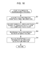
- Fig. 16 is a flowchart illustrating a lower-side rearrangement process.
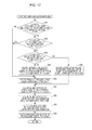
- Fig. 17 is a flowchart illustrating a lower-side selection process.
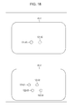
- Fig. 18 is a diagram showing an example of output of a touch panel.
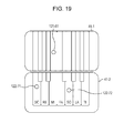
- Fig. 19 is a diagram showing an example of processing by an application.
- Example of a touch panel to which the present disclosure is not applied 2. Configuration of a personal computer 3. Touch information selection process 4. Upper-side rearrangement process 5. Upper-side selection process 6. Lower-side rearrangement process 7. Lower-side selection process 8. Others
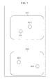
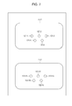
- Fig. 1 is a diagram showing an example of a touch panel 201 in a case where the present disclosure is not applied.
- the example of Fig. 1 shows a state in which the user has touched predetermined positions on a touch panel 201-1 on the upper side and a touch panel 201-2 on the lower side.
- touch panels 201-1 and 201-2 will be hereinafter simply written as touch panel 201 in cases where there is no need to individually distinguish these touch panels from each other. The same applies to other components as well.
- the touch panel 201 is a touch panel display that is capable of multi-touch. The user can input a predetermined operation by touching a plurality of points on the touch panel 201.
- the touch panel 201-1 on the upper side detects the touched points.
- upper-side touch points 221-1 and 221-2 are detected by the touch panel 201-1 on the upper side.
- the touch panel 201 can execute an operation using multi-touch.
- the controller accepts information on each touch point on the touch panel 201-1 at a first timing by an interrupt process, and accepts information on each touch point on the touch panel 201-2 at a second timing by an interrupt process.
- the controller the touch panel 201-1 on the upper side and the touch panel 201-2 on the lower side are detected as being alternately touched, and the fact that the distance between the upper-side touch point 222-1 and the lower-side touch point 222-1 is increasing or decreasing is not detected.
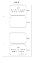
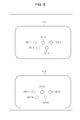
- Fig. 2 is a diagram showing an example of input of the touch panel 201.
- a maximum detection count indicating the maximum number of touch points that can be detected is set for software that controls the touch panel 201.
- Fig. 2 shows a case where the maximum detection count is 5, that is, a case where the number of fingers on one hand of the user is set as the maximum detection count.
- FIG. 2 a case is shown in which the touch panel 201-1 on the upper side detects upper-side touch points 221-11 to 221-15.
- the touch panel 201-2 on the lower side is not touched.
- the upper-side touch points 221-11 to 221-15 are detected and displayed.
- the last touched lower-side touch point 222 is not detected.
- the lower-side touch point 222-16 is touched last after the lower-side touch points 222-11 to 222-15 are touched, the lower-side touch point 222-16 is not detected.
- the lower-side touch points 222-11 to 222-15 are displayed in solid lines, and the lower-side touch point 222-16 is displayed in the broken line.
- the touch panel 201 does not detect any touch point touched after the maximum detection count is exceeded.
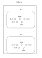
- Fig. 3 is a diagram showing an example of input of the touch panel 201.
- the touch panel 201-1 on the upper side and the touch panel 201-2 on the lower side are handled as a single touch panel. Therefore, the maximum detection count is 5 for the touch panel 201-1 on the upper side and the touch panel 201-2 on the lower side combined together.
- the touch panel 201-1 on the upper side and the touch panel 201-2 on the lower side detect touch points independently.
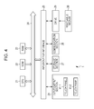
- Fig. 4 is a block diagram showing an example of the hardware configuration of a personal computer 1 as an information processing apparatus according to this embodiment.
- a CPU Central Processing Unit
- ROM Read Only Memory
- RAM Random Access Memory
- the bus 24 is further connected with an input/output interface 25.
- the input/output interface 25 is connected with an input/output section 26, a storage section 27, a communication section 28, and a drive 29.
- the input/output section 26 includes a keyboard, a mouse, a microphone, a display, a speaker, or the like.
- the storage section 27 is formed by a hard disk, a non-volatile memory, or the like.
- the touch panel 41 in this specification is formed by integrating a touch panel as an input device, and a display such as an LCD (Liquid Crystal Display) as an output device.
- a display such as an LCD (Liquid Crystal Display) as an output device.
- the touch panel 41 has two functions of input and output.
- the touch panel 41 detects touch information such as information about a position on the screen touched by a user's finger, a pen, or the like, and also displays predetermined image information or the like.
- the communication section 28 is formed by a network interface or the like.
- the drive 29 drives a removable medium 30 such as a magnetic disc, an optical disc, a magneto-optical disc, or a semiconductor memory.
- the CPU 21 loads a program stored in the storage section 27 into the RAM 23 via the input/output interface 25 and the bus 24, and executes the program, for example.
- the program to be executed by the CPU 21 is provided while being recorded on the removable medium 30 in the form of a packaged medium or the like (i.e., a tangible, non-transitory, computer-readable storage medium), for example.
- a magnetic disc including a flexible disc
- an optical disc such as a CD-ROM (Compact Disc-Read Only Memory) or a DVD (Digital Versatile Disc)
- a magneto-optical disc a semiconductor memory, or the like is used.
- the program can be provided via a wired or wireless transmission medium such as a local area network, the Internet, or digital satellite broadcast.
- the program can be installed into the storage section 27 via the input/output interface 25 by mounting the removable medium 30 in the drive 29.
- the program can be received by the communication section 28 via a wired or wireless transmission medium, and installed into the storage section 27.
- the program can be pre-installed in the ROM 22 or storage section 27.
- the program executed by the personal computer 1 may execute processes in a time-series fashion in the order as described in this specification, or may execute processes in parallel or at necessary timing such as when invoked.
- Fig. 5 is a block diagram showing an example of the functional configuration of the CPU 21.
- the CPU 21 has the functional blocks of a determining section 61, an acquiring section 62, a recording section 63, a control section 64, and an output section 65. It should be noted that the individual blocks of the CPU 21 are able to exchange signals or data with each other as necessary.
- the determining section 61 determines various kinds of information.
- the acquiring section 62 acquires various kinds of information.
- the recording section 63 records various kinds of information.
- the control section 64 performs various kinds of control processing.
- the output section 65 outputs various kinds of information.
- Fig. 6 is a diagram showing an overview of processing by software associated with control of the personal computer 1.
- the software includes an operating system 82 and an application 83, and is controlled by the control section 64.
- the touch panel 41 outputs detected touch information to the operating system 82.
- the touch information is, for example, positional information for each of touch points touched by the user, information for identifying the order in which each touch point is touched (for example, time information or ID (Identification)), or the like.
- Fig. 7 is a diagram showing an example of input of the touch panel 41.
- upper-side touch points 121-1 to 121-5 i.e., first device positions
- lower-side touch points 122-11 to 122-15 i.e., second device positions
- information on each of the detected upper-side touch points 121-1 to 121-5 i.e., first positional information
- information on each of the detected lower-side touch points 122-11 to 122-15 i.e., second positional information
- the touch information is expressed in the form of, for example, "PA(x 1 , y 1 )4, PA(x 2 , y 2 )3, PA(x 3 , y 3 )2, PA(x 4 , y 4 )5, and PA(x 5 , y 5 )1" as shown in Fig. 6.
- PA indicates that a touch point lies on the touch panel 41-1 on the upper side. That is, this indicates that a touch point is detected by the touch panel 41-1 on the upper side.
- PB indicates that a touch point is detected by the touch panel 41-2 on the lower side.
- (x a , y a )" indicates the coordinates of an upper-side touch point 121-a or lower-side touch point 122-a (i.e., first or second spatial coordinates). That is, "PA(x 1 , y 1 )4" indicates the coordinates of the upper-side touch point 121-1.
- the number following the positional information on a touch point indicates the order in which each touch point is touched (i.e., time information), and the smaller the number, the earlier the touch point is touched.
- This number is, for example, a number such as an ID, and appended to information on each of touch points in the order of being touched.
- the operating system 82 executes a process of acquiring touch information from the touch panel 41 and selecting (i.e., identifying) a number of touch points equal to or less than the maximum detection count (i.e., a subset of the first and second device positions), and outputs the detection information, that is, information on each of the selected touch points, to the application 83.
- Fig. 6 illustrates a case where the maximum detection count is 5.
- the operating system 82 acquires "PA(x 1 , y 1 )4, PA(x 2 , y 2 )3, PA(x 3 , y 3 )2, PA(x 4 , y 4 )5, and PA(x 5 , y 5 )1" as touch information from the touch panel 41-1.
- the operating system 82 acquires "PB(x 11 , y 11 )5, PB(x 12 , y 12 )2, PB(x 13 , y 13 )1, PB(x 14 , y 14 )3, and PB(x 15 , y 15 )4" as touch information from the touch panel 41-2.
- the operating system 82 having acquired the touch information executes a process of selecting a number of touch points equal to or less than the maximum detection count, and outputs the selected upper-side detection information and lower-side detection information to the application 83.
- the process of selecting a number of touch points equal to or less than the maximum detection count by the operating system 82, that is, processing in the personal computer 1 will be described later with reference to Fig. 9.
- the touch points are selected in order from the touch point that is touched earliest.
- touch information information on each of touch points is basically acquired in the order of being touched. However, in cases such as when touches occur simultaneously within a short period of time, information on each of touch points may not necessarily be acquired in the order of being touched as shown in Fig. 6.
- PA(x 5 , y 5 )1, PA(x 3 , y 3 )2, and PA(x 2 , y 2 )3" are selected as upper-side detection information
- PB(x 13 , y 13 )1 and PB(x 12 , y 12 )2" are selected as lower-side detection information.
- the five earliest touch points in time are selected from among both the touch panel 41-1 and the touch panel 41-2.
- the upper-side detection information and the lower-side detection information are outputted to the application 83.
- information on each of touch points detected by the touch panel 41-1 on the upper side, and information on each of touch points detected by the touch panel 41-2 on the lower side are outputted to the application 83, as touch information detected by a single touch panel.
- the application 83 executes predetermined processing on the basis of the upper-side detection information and the lower-side detection information acquired from the operating system 82. Referring to Fig. 8, a description will be given of a case where touch points included in the upper-side detection information and lower-side detection information are outputted to the touch panel 41.
- Fig. 8 is a diagram showing an example of output corresponding to the input of the touch panel 41 in Fig. 7.
- the upper-side touch points 121-2, 121-3, and 121-5 are indicated by solid lines, and the upper-side touch points 121-1 and 121-4 are indicated by broken lines on the touch panel 41-1 on the upper side.
- the upper-side touch points 121-2, 121-3, and 121-5 corresponding to the upper-side detection information "PA(x 5 , y 5 )1, PA(x 3 , y 3 )2, and PA(x 2 , y 3 )3" acquired by the application 83 are displayed on the touch panel 41-1 on the upper side.
- the lower-side touch points 122-12 and 122-13 are indicated by solid lines, and the lower-side touch points 122-11, 122-14, and 122-15 are indicated by broken lines.
- the lower-side touch points 122-12 and 122-13 corresponding to the lower-side detection information "PB(x 13 , y 13 )1 and PB(x 12 , y 12 )2" acquired by the application 83 are displayed on the touch panel 41-2 on the lower side.
- the operating system 82 can execute predetermined processing by combining and handling the touch panel 41-1 on the upper side and the touch panel 41-2 on the lower side as a single touch panel.
- the operating system 82 executes predetermined processing by selecting a number of pieces of touch information equal to or less than the maximum detection count.
- Fig. 6 While the example of Fig. 6 is directed to the case where the operating system 82 executes a process of selecting a number of touch points equal to or less than the maximum detection count, the process may be executed by any one of a device driver within the operating system 82, a layer of the operating system 82 other than the device driver, and middleware.
- the same process may be executed not only by the operating system 82 but by the application 83.
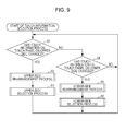
- Fig. 9 is a flowchart illustrating the touch information selection process by the personal computer 1.
- the touch information selection process in Fig. 9 is started when the personal computer 1 is activated, and is thereafter executed continuously.
- step S1 the determining section 61 determines whether or not touch information on the touch panel 41-1 on the upper side has changed. That is, it is determined whether or not the number of upper-side touch points 121 on the touch panel 41-1 on the upper side has increased or decreased.
- the determining section 61 determines whether or not touch information on the touch panel 41-2 on the lower side has changed.
- step S1 If the number of lower-side touch points 122 on the touch panel 41-2 on the lower side has not increased or decreased, the processing returns to step S1. That is, if the number of touch points does not change, the processes of steps S1 and S4 are repeated.
- step S1 If it is determined in step S1 that touch information on the touch panel 41-1 on the upper side has changed, the processing proceeds to step S2. Referring to Figs. 10 and 11, a case where touch information on the touch panel 41-1 on the upper side changes will be described.
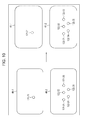
- Fig. 10 is a diagram showing an example of input and output of the touch panel 41 in the initial state.
- Fig. 11 is a diagram showing an example of input of the touch panel 41.
- the left-hand side of Fig. 10 is a diagram showing the state of input of the touch panel 41.
- the left-hand side of Fig. 10 shows a state in which the touch panel 41-1 on the upper side has detected an upper-side touch point 121-21, and the touch panel 41-2 on the lower side has detected lower-side touch points 122-31 to 122-35.
- the right-hand side of Fig. 10 is a diagram showing the state of output of the touch panel 41.
- the right-hand side of Fig. 10 shows a state in which the touch panel 41-1 on the upper side does not output the upper-side touch point 121-21, and the touch panel 41-2 on the lower side outputs the lower-side touch points 122-31 to 122-35.
- Fig. 11 is a diagram showing an example of input of the touch panel 41.
- upper-side touch points 121-41 and 121-42 are detected by the touch panel 41-1 on the upper side
- lower-side touch points 122-31 to 122-35 are detected by the touch panel 41-2 on the lower side.
- step S2 the personal computer 1 executes an upper-side rearrangement process. Referring to Fig. 12, the upper-side rearrangement process will be described.
- Fig. 12 is a flowchart illustrating an upper-side rearrangement process by the personal computer 1.
- step S21 the acquiring section 62 acquires touch information from the touch panel 41-1 on the upper side. That is, in the example of Fig. 11, information on each of the upper-side touch points 121-41 and 121-42 is acquired as touch information.
- step S22 the recording section 63 records the number of upper-side touch points 121 in the upper-side output count and the upper-side touch count. That is, in the example of Fig. 11, 2 as the number of upper-side touch points 121 is substituted into the upper-side output count and the upper-side touch count.
- the upper-side output count is a value indicating the number of upper-side touch points 121 outputted to the touch panel 41-1 on the upper side or the application 83.
- the upper-side touch count is a value indicating the number of upper-side touch points 121 detected by the touch panel 41-1 on the upper side. That is, this value indicates the number of points that have been actually touched by the user.
- step S23 the control section 64 rearranges touch information in the order of being touched. Touch information may not necessarily be acquired in the order of being touched. Therefore, information on each of the upper-side touch points 121 acquired is rearranged in the order of being touched.
- touch information is rearranged in the order of the upper-side touch point 121-41 and the upper-side touch point 121-42.
- step S23 can be omitted.
- step S24 the recording section 63 records the touch information rearranged by the process of step S23, in upper-side detection information. After the process of step S24, the upper-side rearrangement process ends, and the processing proceeds to step S3 in Fig. 9.
- step S3 in Fig. 9 the personal computer 1 executes an upper-side selection process. Referring to Fig. 13, the upper-side selection process will be described.
- Fig. 13 is a flowchart illustrating an upper-side selection process by the personal computer 1.
- step S41 the determining section 61 determines whether or not the sum of the upper-side output count and the lower-side touch count is larger than the maximum detection count.
- the upper-side output count becomes the same as the number of upper-side touch points 121 recorded by the process of step S22 in Fig. 12.
- step S41 it is determined by the process of step S41 whether or not the total sum of the number of upper-side touch points 121 detected by the touch panel 41-1 on the upper side, and the number of lower-side touch points 122 detected by the touch panel 41-2 on the lower side exceeds the maximum detection count.
- step S42 the determining section 61 determines whether or not the upper-side output count is equal to the previous upper-side output count.
- the upper-side output count is 2, and the previous upper-side output count is 0 as shown in Fig. 10.
- the upper-side output count and the previous upper-side output count take different numerical values.
- step S42 If it is determined in step S42 that the upper-side output count is not equal to the previous upper-side output count, in step S43, the determining section 61 determines whether or not the upper-side output count is larger than the previous upper-side output count.
- the previous upper-side output count is 0.
- the upper-side output count is larger than the previous upper-side output count.
- step S44 the recording section 63 records the difference obtained by subtracting the previous lower-side output count from the maximum detection count, in the upper-side output count.
- the number of upper-side touch points 121 if the number of upper-side touch points 121 has increased, the number of upper-side touch points 121 outputted to the touch panel 41-1 on the upper side is adjusted within a range not exceeding the maximum detection count.
- step S41 If it is determined in step S41 that the sum of the upper-side output count and the lower-side touch count is equal to or less than the maximum detection count, if it is determined in step S42 that the upper-side output count is equal to the previous upper-side output count, and after the process of step S44, the processing proceeds to step S45.
- step S45 the recording section 63 records the previous lower-side output count in the lower-side output count.
- the previous lower-side output count is 5, so 5 is substituted into the lower-side output count. That is, the number of lower-side output points outputted to the touch panel 41-2 on the lower side does not change.
- step S46 the recording section 63 records the difference obtained by subtracting the upper-side output count from the maximum detection count, in the lower-side output count.
- the number of upper-side touch points 121 has decreased, the number of lower-side touch points 122 outputted to the touch panel 41-2 on the lower side is adjusted within a range not exceeding the maximum detection count.
- step S47 the acquiring section 62 acquires a number of pieces of upper-side detection information equal to the upper-side output count. That is, information on each of the upper-side touch points 121 to be outputted is selected.
- the upper-side output count is 0, and thus no upper-side detection information is acquired. That is, touches on the upper-side touch points 121-41 and 121-42 on the touch panel 41-1 on the upper side are ignored.
- step S48 the acquiring section 62 acquires a number of pieces of lower-side detection information equal to the lower-side output count. That is, information on each of the lower-side touch points 122 to be outputted is selected.
- the lower-side output count is 5.
- information on each of five lower-side touch points 122 that is, information on each of the lower-side touch points 122-31 to 122-35 is acquired from the lower-side detection information.
- step S49 the output section 65 outputs the acquired upper-side detection information and lower-side detection information. That is, the upper-side detection information and the lower-side detection information acquired by the processes of steps S47 and S48 are outputted to at least one of the touch panel 41 and the application 83.
- Fig. 14 is a diagram showing an example of output corresponding to the input of the touch panel 41 in Fig. 11.
- the upper-side touch points 121-41 and 121-42 are indicated by broken lines. That is, touches on the touch panel 41-1 on the upper side are ignored, and the upper-side touch points 121-41 and 121-42 are not displayed.
- the lower-side touch points 122-31 to 122-35 are indicated by solid lines. That is, on the touch panel 41-2 on the lower side, five points are determined as being touched, and the lower-side touch points 122-31 to 122-35 are displayed.
- step S50 the recording section 63 records the upper-side output count in the previous upper-side output count. As shown in Fig. 14, the upper-side output count is 0, so 0 is substituted into the previous upper-side output count.
- step S50 After the process of step S50, the upper-side selection process ends, and the processing returns to step S1 in Fig. 9.
- step S4 determines whether or not touch information on the touch panel 41-2 on the lower side has changed.
- step S4 If it is determined in step S4 that touch information on the touch panel 41-2 on the lower side has changed, the processing proceeds to step S5.
- step S5 Referring to Figs. 11 and 15, a description will be given of a case where touch information on the touch panel 41-1 on the lower side has changed.
- Fig. 15 is a diagram showing an example of input of the touch panel 41.
- the example of Fig. 15 shows a state in which the touch panel 41-1 on the upper side has detected the upper-side touch points 121-41 and 121-42, and the touch panel 41-2 on the lower side has detected lower-side touch points 122-51 to 122-54.
- step S4 in Fig. 9 it is determined that touch information on the touch panel 41-2 on the lower side has changed.
- step S5 in Fig. 9 the personal computer 1 executes a lower-side rearrangement process.
- the lower-side rearrangement process will be described.
- Fig. 16 is a flowchart illustrating a lower-side rearrangement process by the personal computer 1. It should be noted that the processes of steps S61 to S64 in Fig. 16 are processes corresponding to steps S21 to S24 in Fig. 12.
- step S61 the acquiring section 62 acquires touch information from the touch panel 41-2 on the lower side. That is, in the example of Fig. 15, information on each of the lower-side touch points 122-51 and 122-54 is acquired as touch information.
- step S62 the recording section 63 records the number of lower-side touch points 122 in the lower-side output count and the lower-side touch count. That is, in the example of Fig. 15, 4 as the number of lower-side touch points 122 is substituted into the lower-side output count and the lower-side touch count.
- the lower-side output count is a value indicating the number of lower-side touch points 122 outputted to the touch panel 41-2 on the lower side or the application 83.
- the lower-side touch count is a value indicating the number of lower-side touch points 122 detected by the touch panel 41-2 on the lower side.
- step S63 the control section 64 rearranges touch information in the order of being touched.
- touch information is rearranged in the order of the lower-side touch points 122-51, 122-52, 122-53, and 122-54.
- step S63 can be omitted.
- step S64 the recording section 63 records the touch information rearranged by the process of step S63, in lower-side detection information. After the process of step S64, the lower-side rearrangement process ends, and the processing proceeds to step S6 in Fig. 9.
- step S6 in Fig. 9 the personal computer executes a lower-side selection process. Referring to Fig. 17, the lower-side selection process will be described.
- Fig. 17 is a flowchart illustrating a lower-side selection process by the personal computer 1. It should be noted that the processes of steps S81 to S90 in Fig. 17 are processes corresponding to steps S41 to S50 in Fig. 13.
- step S81 the determining section 61 determines whether or not the sum of the upper-side output count and the lower-side touch count is larger than the maximum detection count.
- step S82 the determining section 61 determines whether or not the lower-side output count is equal to the previous lower-side output count.
- the lower-side output count is 4, and the previous lower-side output count is 5 as shown in Fig. 14.
- the lower-side output count and the previous lower-side output count take different numerical values.
- step S83 the determining section 61 determines whether or not the lower-side output count is larger than the previous lower-side output count.
- step S84 the recording section 63 records the difference obtained by subtracting the previous upper-side output count from the maximum detection count, in the lower-side output count.
- the number of lower-side touch points 122 if the number of lower-side touch points 122 has increased, the number of lower-side touch points 122 outputted to the touch panel 41-2 on the lower side is adjusted within a range not exceeding the maximum detection count.
- step S81 If it is determined in step S81 that the sum of the lower-side output count and the upper-side touch count is equal to or less than the maximum detection count, if it is determined in step S82 that the lower-side output count is equal to the previous lower-side output count, and after the process of step S84, the processing proceeds to step S85.
- step S85 since the upper-side output count has not changed, the recording section 63 records the previous upper-side output count in the upper-side output count.
- step S86 the recording section 63 records the difference obtained by subtracting the lower-side output count from the maximum detection count, in the upper-side output count.
- the number of lower-side touch points 122 has decreased, the number of upper-side touch points 121 outputted to the touch panel 41-1 on the upper side is adjusted within a range not exceeding the maximum detection count.
- the lower-side output count is 4.
- the difference obtained by subtracting the lower-side output count from the maximum detection count of 5 becomes 1. Therefore, 1 is substituted into the upper-side output count.
- step S87 the acquiring section 62 acquires a number of pieces of upper-side detection information equal to the upper-side output count. That is, information on each of the lower-side touch points 122 to be outputted is selected.
- the upper-side output count is 1.
- information on a single upper-side touch point 121 that is, information on the upper-side touch point 121-41 is acquired from the upper-side detection information.
- step S88 the acquiring section 62 acquires a number of pieces of lower-side detection information equal to the lower-side output count.
- the lower-side output count is 4.
- information on each of four lower-side touch points 122 that is, information on each of the lower-side touch points 122-51 to 122-54 is acquired from the lower-side detection information.
- step S89 the output section 65 outputs the acquired upper-side detection information and lower-side detection information. That is, the upper-side detection information and the lower-side detection information acquired by the processes of steps S87 and S88 are outputted to at least one of the touch panel 41 and the application 83.
- Fig. 18 is a diagram showing an example of output corresponding to the input of the touch panel 41 in Fig. 15. As shown in Fig. 18, on the touch panel 41-1 on the upper side, the upper-side touch point 121-41 is indicated by a solid line, and the upper-side touch point 121-42 are indicated by a broken line.
- the lower-side touch points 122-51 to 122-54 are indicated by solid lines. That is, on the touch panel 41-2 on the lower side, four points are determined as being touched, and the lower-side touch points 122-51 to 122-54 are displayed.
- step S90 the recording section 63 records the lower-side output count in the previous lower-side output count. As shown in Fig. 18, the lower-side output count is 4, so 4 is substituted into the previous lower-side output count.
- step S90 After the process of step S90, the upper-side selection process ends, and the processing returns to step S1 in Fig. 9.
- the personal computer 1 can reliably execute more diverse processing while combining and regarding the touch panel 41-1 and the touch panel 41-2 as a single touch panel.
- Fig. 19 is a diagram showing an example of processing by the application 83.
- the example of Fig. 19 shows an application that executes playing of a piano.
- the upper-side touch point 121-61 is displayed on the image of the key "mi".
- the lower-side touch point 122-71 is displayed on the image of the key "do"
- the lower-side touch point 122-72 is displayed on the image of the key "so”.
- chord of "do”, “mi”, and “so” is outputted also when the key “mi” on the touch panel 41-2 on the lower side is operated, since the touch panel 41-1 on the upper side and the touch panel 41-2 on the lower side are handled integrally in the present disclosure, the chord is outputted in this case as well.
- predetermined processing can be executed reliably on the basis of the upper-side touch points 121 and the lower-side touch points 122 selected so as to be equal to or less than the maximum detection count of touch points.
- system means an entire apparatus made up of a plurality of apparatuses, means, or the like.
- An embodiment of the present disclosure is not limited to the above-mentioned embodiment, but various changes are possible without departing from the scope of the present disclosure. Also, in the embodiment of the present disclosure, some of functions may be included in another apparatus.
- the maximum detection count is set as 5
- the maximum detection count can be set as, for example, the smaller one of the maximum detection count for the software that controls the touch panel 41-1 and the maximum detection count for the software that controls the touch panel 41-2.
- the maximum detection count may be set to an arbitrary number by the application or the like.
- the upper-side touch points 121 and the lower-side touch points 122 are displayed on the touch panel 41, the upper-side touch points 121 and the lower-side touch points 122 may not be displayed on the touch panel 41.
- the touch panel 41 is formed by integrating an input device and an output device, another display apparatus may be used as an output device, and the touch panel 41 may have only the function of an input device.
- the present disclosure can be also applied to information processing apparatuses such as smartphones, tablets, and digital signage.
- An information processing apparatus including a plurality of touch panels that detect touch information, and a control section that performs control so as to execute predetermined processing, while handling the touch information detected by the plurality of touch panels as touch information detected by a single touch panel.
- the information processing apparatus further including an acquiring section that acquires the touch information, in which the acquiring section acquires a number of pieces of the touch information equal to or less than a maximum detection count, when a total sum of pieces of the touch information detected by the plurality of touch panels exceeds the maximum detection count, and the control section performs control so as to execute the predetermined processing, on a basis of the number of pieces of the touch information equal to or less than the maximum detection count which are acquired by the acquiring section.
- the control section rearranges the touch information detected by the plurality of touch panels in an order of being touched for each of the touch panels, and the acquiring section acquires sequentially from the touch information that is touched earliest.
- the control section adjusts a number of pieces of the touch information on the first touch panel, when the number of pieces of the touch information on the first touch panel has increased, or when a number of pieces of the touch information on the second touch panel has decreased, and adjusts the number of pieces of the touch information on the second touch panel, when the number of pieces of the touch information on the first touch panel has decreased, or when the number of pieces of the touch information on the second touch panel has increased.
- the maximum detection count is set as a smaller one of a maximum detection count for the first touch panel and a maximum detection count for the second touch panel.
Landscapes
- Engineering & Computer Science (AREA)
- General Engineering & Computer Science (AREA)
- Theoretical Computer Science (AREA)
- Human Computer Interaction (AREA)
- Physics & Mathematics (AREA)
- General Physics & Mathematics (AREA)
- User Interface Of Digital Computer (AREA)
- Position Input By Displaying (AREA)
Priority Applications (5)
| Application Number | Priority Date | Filing Date | Title |
|---|---|---|---|
| BR112013024245-0A BR112013024245A2 (pt) | 2011-03-29 | 2012-03-22 | método para identificar um subconjunto de posições de toque, aparelho para prover uma interface de usuário, e, meio legível por computador. |
| EP20120765058 EP2691843A4 (en) | 2011-03-29 | 2012-03-22 | INFORMATION PROCESSING APPARATUS AND METHOD, RECORDING MEDIUM, AND PROGRAM |
| CN2012800144187A CN103460167A (zh) | 2011-03-29 | 2012-03-22 | 信息处理设备和信息处理方法、记录介质以及程序 |
| US14/000,422 US20130328818A1 (en) | 2011-03-29 | 2012-03-22 | Information processing apparatus and information processing method, recording medium, and program |
| RU2013142981/08A RU2013142981A (ru) | 2011-03-29 | 2012-03-22 | Устройство обработки информации и способ обработки информации, носитель записи и программа |
Applications Claiming Priority (2)
| Application Number | Priority Date | Filing Date | Title |
|---|---|---|---|
| JP2011072377A JP5884282B2 (ja) | 2011-03-29 | 2011-03-29 | 情報処理装置および情報処理方法、記録媒体、並びにプログラム |
| JP2011-072377 | 2011-03-29 |
Publications (1)
| Publication Number | Publication Date |
|---|---|
| WO2012132343A1 true WO2012132343A1 (en) | 2012-10-04 |
Family
ID=46930125
Family Applications (1)
| Application Number | Title | Priority Date | Filing Date |
|---|---|---|---|
| PCT/JP2012/001977 WO2012132343A1 (en) | 2011-03-29 | 2012-03-22 | Information processing apparatus and information processing method, recording medium, and program |
Country Status (7)
Cited By (1)
| Publication number | Priority date | Publication date | Assignee | Title |
|---|---|---|---|---|
| CN109831686A (zh) * | 2013-02-13 | 2019-05-31 | 索尼公司 | 信息处理设备、信息处理方法和信息处理系统 |
Families Citing this family (3)
| Publication number | Priority date | Publication date | Assignee | Title |
|---|---|---|---|---|
| WO2014008670A1 (zh) * | 2012-07-13 | 2014-01-16 | 华为技术有限公司 | 确定操作对象的方法和终端 |
| US11175782B2 (en) | 2018-05-11 | 2021-11-16 | Mitsubishi Electric Corporation | Input control device and input control method |
| CN108776553A (zh) * | 2018-06-11 | 2018-11-09 | 业成科技(成都)有限公司 | 双面触控显示模组及其触发方法 |
Citations (8)
| Publication number | Priority date | Publication date | Assignee | Title |
|---|---|---|---|---|
| US6144358A (en) * | 1997-08-20 | 2000-11-07 | Lucent Technologies Inc. | Multi-display electronic devices having open and closed configurations |
| US20090231288A1 (en) * | 2008-03-17 | 2009-09-17 | Inventec Corporation | Hand-held electronic device and combined input method thereof |
| US20090244016A1 (en) | 2008-03-31 | 2009-10-01 | Dell Products, Lp | Information handling system display device and methods thereof |
| US20090267903A1 (en) * | 2008-04-23 | 2009-10-29 | Motorola, Inc. | Multi-Touch Detection Panel with Disambiguation of Touch Coordinates |
| US20090322689A1 (en) * | 2008-06-30 | 2009-12-31 | Wah Yiu Kwong | Touch input across touch-sensitive display devices |
| JP2010184042A (ja) * | 2009-02-12 | 2010-08-26 | Konami Digital Entertainment Co Ltd | 表示装置、表示方法、ならびに、プログラム |
| US20100259494A1 (en) * | 2009-04-14 | 2010-10-14 | Sony Corporation | Information processing apparatus, information processing method, and program |
| US20110209104A1 (en) * | 2010-02-25 | 2011-08-25 | Microsoft Corporation | Multi-screen synchronous slide gesture |
Family Cites Families (25)
| Publication number | Priority date | Publication date | Assignee | Title |
|---|---|---|---|---|
| JPH04326152A (ja) * | 1991-04-25 | 1992-11-16 | Hitachi Ltd | パーソナル情報機器 |
| US6331840B1 (en) * | 1998-03-27 | 2001-12-18 | Kevin W. Nielson | Object-drag continuity between discontinuous touch screens of a single virtual desktop |
| JP2001154807A (ja) * | 1999-11-29 | 2001-06-08 | Hitachi Ltd | 座標入力表示システムおよび座標入力表示装置 |
| US8525799B1 (en) * | 2007-04-24 | 2013-09-03 | Cypress Semiconductor Conductor | Detecting multiple simultaneous touches on a touch-sensor device |
| CN100590579C (zh) * | 2007-05-16 | 2010-02-17 | 广东威创视讯科技股份有限公司 | 一种多点触摸定位方法 |
| WO2009049331A2 (en) * | 2007-10-08 | 2009-04-16 | Van Der Westhuizen Willem Mork | User interface |
| KR101407300B1 (ko) * | 2007-11-19 | 2014-06-13 | 엘지디스플레이 주식회사 | 멀티 터치 평판 표시모듈 |
| JP2009211547A (ja) * | 2008-03-05 | 2009-09-17 | Seiko Epson Corp | 表示システム、表示装置及びプログラム |
| EP2291729B1 (en) * | 2008-04-30 | 2013-06-05 | N-Trig Ltd. | Multi-touch detection |
| TW200951783A (en) * | 2008-06-06 | 2009-12-16 | Acer Inc | Electronic device and controlling method thereof |
| US20100162128A1 (en) * | 2008-12-19 | 2010-06-24 | Nigel Richardson | User interfaces and associated apparatus and methods |
| JP5344555B2 (ja) * | 2008-10-08 | 2013-11-20 | シャープ株式会社 | オブジェクト表示装置、オブジェクト表示方法、およびオブジェクト表示プログラム |
| US8330733B2 (en) * | 2009-01-21 | 2012-12-11 | Microsoft Corporation | Bi-modal multiscreen interactivity |
| JP5229083B2 (ja) * | 2009-04-14 | 2013-07-03 | ソニー株式会社 | 情報処理装置、情報処理方法及びプログラム |
| US8355007B2 (en) * | 2009-05-11 | 2013-01-15 | Adobe Systems Incorporated | Methods for use with multi-touch displays for determining when a touch is processed as a mouse event |
| US20100302190A1 (en) * | 2009-06-02 | 2010-12-02 | Elan Microelectronics Corporation | Multi-functional touchpad remote controller |
| US8462134B2 (en) * | 2009-06-29 | 2013-06-11 | Autodesk, Inc. | Multi-finger mouse emulation |
| JP2011048610A (ja) * | 2009-08-27 | 2011-03-10 | Jvc Kenwood Holdings Inc | 画像表示システム、及び画像表示方法 |
| US20110175827A1 (en) * | 2009-12-04 | 2011-07-21 | Adam Bogue | Filtering Input Streams in a Multi-Touch System |
| US20110169750A1 (en) * | 2010-01-14 | 2011-07-14 | Continental Automotive Systems, Inc. | Multi-touchpad multi-touch user interface |
| US20110273393A1 (en) * | 2010-05-06 | 2011-11-10 | Wai Keung Wu | Method and Apparatus for Distributed Computing with Proximity Sensing |
| US9158401B2 (en) * | 2010-07-01 | 2015-10-13 | Flatfrog Laboratories Ab | Data processing in relation to a multi-touch sensing apparatus |
| US9372618B2 (en) * | 2010-10-01 | 2016-06-21 | Z124 | Gesture based application management |
| KR20120091975A (ko) * | 2011-02-10 | 2012-08-20 | 삼성전자주식회사 | 적어도 두 개의 터치 스크린을 포함하는 정보 표시 장치 및 그의 정보 표시 방법 |
| KR101842906B1 (ko) * | 2011-02-10 | 2018-05-15 | 삼성전자주식회사 | 복수의 터치스크린을 가지는 장치 및 복수의 터치스크린을 가지는 장치의 화면 변경방법 |
-
2011
- 2011-03-29 JP JP2011072377A patent/JP5884282B2/ja not_active Expired - Fee Related
-
2012
- 2012-03-22 WO PCT/JP2012/001977 patent/WO2012132343A1/en active Application Filing
- 2012-03-22 US US14/000,422 patent/US20130328818A1/en not_active Abandoned
- 2012-03-22 BR BR112013024245-0A patent/BR112013024245A2/pt not_active IP Right Cessation
- 2012-03-22 CN CN2012800144187A patent/CN103460167A/zh active Pending
- 2012-03-22 RU RU2013142981/08A patent/RU2013142981A/ru unknown
- 2012-03-22 EP EP20120765058 patent/EP2691843A4/en not_active Withdrawn
Patent Citations (8)
| Publication number | Priority date | Publication date | Assignee | Title |
|---|---|---|---|---|
| US6144358A (en) * | 1997-08-20 | 2000-11-07 | Lucent Technologies Inc. | Multi-display electronic devices having open and closed configurations |
| US20090231288A1 (en) * | 2008-03-17 | 2009-09-17 | Inventec Corporation | Hand-held electronic device and combined input method thereof |
| US20090244016A1 (en) | 2008-03-31 | 2009-10-01 | Dell Products, Lp | Information handling system display device and methods thereof |
| US20090267903A1 (en) * | 2008-04-23 | 2009-10-29 | Motorola, Inc. | Multi-Touch Detection Panel with Disambiguation of Touch Coordinates |
| US20090322689A1 (en) * | 2008-06-30 | 2009-12-31 | Wah Yiu Kwong | Touch input across touch-sensitive display devices |
| JP2010184042A (ja) * | 2009-02-12 | 2010-08-26 | Konami Digital Entertainment Co Ltd | 表示装置、表示方法、ならびに、プログラム |
| US20100259494A1 (en) * | 2009-04-14 | 2010-10-14 | Sony Corporation | Information processing apparatus, information processing method, and program |
| US20110209104A1 (en) * | 2010-02-25 | 2011-08-25 | Microsoft Corporation | Multi-screen synchronous slide gesture |
Non-Patent Citations (1)
| Title |
|---|
| See also references of EP2691843A4 |
Cited By (2)
| Publication number | Priority date | Publication date | Assignee | Title |
|---|---|---|---|---|
| CN109831686A (zh) * | 2013-02-13 | 2019-05-31 | 索尼公司 | 信息处理设备、信息处理方法和信息处理系统 |
| CN109831686B (zh) * | 2013-02-13 | 2021-07-06 | 索尼公司 | 信息处理设备、信息处理方法和信息处理系统 |
Also Published As
| Publication number | Publication date |
|---|---|
| US20130328818A1 (en) | 2013-12-12 |
| BR112013024245A2 (pt) | 2018-06-26 |
| EP2691843A1 (en) | 2014-02-05 |
| RU2013142981A (ru) | 2015-03-27 |
| JP2012208609A (ja) | 2012-10-25 |
| CN103460167A (zh) | 2013-12-18 |
| JP5884282B2 (ja) | 2016-03-15 |
| EP2691843A4 (en) | 2014-12-24 |
Similar Documents
| Publication | Publication Date | Title |
|---|---|---|
| US8624841B2 (en) | Method and apparatus for displaying touch screen keyboard | |
| EP3623929B1 (en) | Scrolling method of mobile terminal and apparatus for performing the same | |
| JP5768457B2 (ja) | 電子機器、表示方法及びプログラム | |
| JP5900500B2 (ja) | 携帯電子機器及びキー表示プログラム | |
| US20110093816A1 (en) | Data display method and mobile device adapted to thereto | |
| JP2006345209A (ja) | 入力装置、情報処理装置、情報処理方法、及びプログラム | |
| WO2012132343A1 (en) | Information processing apparatus and information processing method, recording medium, and program | |
| JP4823369B2 (ja) | 情報処理装置 | |
| EP1986082A1 (en) | Track information processor, track information processing method, information recording medium, and program | |
| US11334160B2 (en) | Signal processing device, signal processing method, and electronic device | |
| EP2759920B1 (en) | Method and apparatus for controlling content playback | |
| US11803289B2 (en) | Icon display controlling device and computer-readable medium for controlling icon display | |
| KR101459447B1 (ko) | 터치스크린을 이용한 항목 선택 방법 및 시스템 | |
| JP2010101977A (ja) | 画像表示装置、動作制御方法及びプログラム | |
| KR20130097624A (ko) | 화면 상의 디스플레이창을 이동시키는 디바이스 및 방법 | |
| US20110199309A1 (en) | Input Device | |
| JP5343386B2 (ja) | タッチパネル入力方式及び入力キー決定方法、タッチパネル入力キー決定プログラム並びにプログラム媒体 | |
| CN116755604A (zh) | 数据处理装置及数据处理方法 | |
| US20110234501A1 (en) | Electronic apparatus | |
| US9189878B2 (en) | Display controller, display control method, and recording medium that stores program | |
| JP6333134B2 (ja) | 情報処理装置、情報処理方法及びプログラム | |
| JPWO2010098383A1 (ja) | 認証装置、認証方法及びそれをコンピュータに実行させるプログラム | |
| US12079393B2 (en) | Tactile feedback | |
| CN116661649A (zh) | 数据处理装置及数据处理方法 | |
| KR100734419B1 (ko) | 디스플레이장치 |
Legal Events
| Date | Code | Title | Description |
|---|---|---|---|
| 121 | Ep: the epo has been informed by wipo that ep was designated in this application |
Ref document number: 12765058 Country of ref document: EP Kind code of ref document: A1 |
|
| WWE | Wipo information: entry into national phase |
Ref document number: 14000422 Country of ref document: US |
|
| REEP | Request for entry into the european phase |
Ref document number: 2012765058 Country of ref document: EP |
|
| WWE | Wipo information: entry into national phase |
Ref document number: 2012765058 Country of ref document: EP |
|
| ENP | Entry into the national phase |
Ref document number: 2013142981 Country of ref document: RU Kind code of ref document: A |
|
| NENP | Non-entry into the national phase |
Ref country code: DE |
|
| REG | Reference to national code |
Ref country code: BR Ref legal event code: B01A Ref document number: 112013024245 Country of ref document: BR |
|
| ENP | Entry into the national phase |
Ref document number: 112013024245 Country of ref document: BR Kind code of ref document: A2 Effective date: 20130920 |