WO2012132226A1 - 摩耗試験装置 - Google Patents
摩耗試験装置 Download PDFInfo
- Publication number
- WO2012132226A1 WO2012132226A1 PCT/JP2012/001349 JP2012001349W WO2012132226A1 WO 2012132226 A1 WO2012132226 A1 WO 2012132226A1 JP 2012001349 W JP2012001349 W JP 2012001349W WO 2012132226 A1 WO2012132226 A1 WO 2012132226A1
- Authority
- WO
- WIPO (PCT)
- Prior art keywords
- test piece
- polishing body
- flat surface
- surface portion
- abrasive
- Prior art date
- Legal status (The legal status is an assumption and is not a legal conclusion. Google has not performed a legal analysis and makes no representation as to the accuracy of the status listed.)
- Ceased
Links
Images


Classifications
-
- G—PHYSICS
- G01—MEASURING; TESTING
- G01N—INVESTIGATING OR ANALYSING MATERIALS BY DETERMINING THEIR CHEMICAL OR PHYSICAL PROPERTIES
- G01N3/00—Investigating strength properties of solid materials by application of mechanical stress
- G01N3/56—Investigating resistance to wear or abrasion
Definitions
- the present invention wears a tread rubber test piece by pressing a test piece made of an elastic material such as a rubber material constituting a tread portion of the tire onto a flat surface of an abrasive body that is relatively displaced with respect to the test piece.
- the present invention relates to a wear test apparatus that measures the quantity with a high correlation with an actual tire. Specifically, in the wear test, the circumferential direction and the width direction within the contact surface during load rolling of the actual tire.
- the present invention proposes a technique capable of faithfully reproducing the shear stress state and the ground pressure state, and predicting tire wear with high accuracy.
- Patent Document 1 states that “a wear test in which a belt-like abrasive body is mounted between a pair of rollers each having a drive source connected to at least one, and a sample support mechanism is installed to press the sample against the flat surface of the abrasive body. According to this wear test device, “wear can be accurately simulated when a rubber sample constituting a tire tread is used as a sample”.
- Patent Document 2 states that “a rubber tester that tests a rubber test piece by pressing a rubber test piece against a grindstone or a pseudo road surface, and displaces the rubber test piece with respect to the grindstone or the pseudo road surface.
- the rubber test piece is characterized by providing adhesion and / or slip to the grindstone or simulated road surface.
- actual products such as tires are worn out”. It was possible to realize a rubber testing machine that can accurately reproduce the behavior of rubber at the time, and accurately match the measured rubber wear level to the actual wear result. .
- a “rubber test piece” or the like is moved only in the vertical direction with respect to the “abrasive body” or “whetstone or simulated road surface” that moves in the horizontal direction. Since it is displaced and pressed, the wear on the tread contact surface of the tire that actually loads and rolls on the road surface cannot be predicted with sufficiently high accuracy.
- An object of the present invention is to solve such problems of the prior art, and the object of the present invention is to provide circumferential and widthwise shear stresses on the ground contact surface during load rolling of a tire. In addition, it is an object of the present invention to provide a wear test apparatus that can faithfully reproduce the ground contact pressure condition and thereby predict tire wear with high accuracy.
- the inventor paid attention to the action of force and slip on the microelements in the tread contact surface at the time of rolling load of the tire, and the microelements include the contact pressure of the rubber material on the road surface and shear due to the slip.
- the shearing force acting on the minute elements in the contact surface between the stepping on the land portion of the tire and the kicking out is shown as a graph in FIG. 1 over time. I found that it changed.
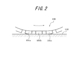
- the tread block of the tire 100 that freely rolls in the direction indicated by the arrow is mainly based on adhesion with the road surface 110 when the tread block 101a is reached.
- the shear stress decreases to the position 101b immediately below the load, increases in the opposite direction toward the kicking position 101c, and reaches the kicking position 101c.
- slip occurs between the road surface 110 and a large shear stress acts instantaneously.
- release of the tread block from the ground contact surface causes the circumferential shear stress to rapidly decrease.
- the tread contact surface since the tread contact surface is pushed and deformed by the action of the contact pressure, the tread block is substantially parallel to the road surface between the stepping position 101a and the kicking position 101c. Will come into contact.
- the wear test apparatus of the present invention comprises an endless annular abrasive body, a pair of abrasive rollers around which the abrasive body is wound and at least one of which can be rotationally driven, and an elastic material.
- a test piece holding means for holding the test piece and separating and approaching the test piece with respect to the flat surface portion on the outer peripheral side of the polishing body, and pressing the test piece against the flat surface portion of the polishing body Measuring the amount of wear of the test piece, the front side of the flat surface portion in the running direction of the flat surface portion pressing the test piece of the abrasive body wound around the abrasive roller that is rotationally driven around the test piece, and A reciprocating drive means for providing a displacement parallel to the flat surface portion to the rear side is provided.
- the reciprocating drive means is not only for displacement of the test piece in the running direction of the flat surface portion but also in parallel to the flat surface portion in a direction perpendicular to the running direction of the flat surface portion. It is preferable to make it possible to make a large displacement.
- a three-component force sensor for measuring forces in three directions in the circumferential direction and width direction of the polishing body and in a direction perpendicular to the outer peripheral surface of the polishing body is attached to a plurality of locations in the circumferential direction of the polishing body.
- the rotational speed of the polishing body roller, the pressing force of the test piece against the flat surface portion of the polishing body by the test piece holding means, and the test piece by the reciprocating drive means Control means for feedback control of the displacement speed is provided.
- the test piece is placed on the flat surface portion of the outer peripheral surface of the endless abrasive that is wound around the pair of abrasive rollers and can be driven in the circumferential direction by the test piece holding means.
- the test piece In the state where the test piece is pressed onto the polishing body, the test piece is directed toward the front side or the rear side in the traveling direction of the flat surface portion, for example, on the polishing body.
- the polishing body is an endless ring that is driven to travel, the abrasion powder generated when the test piece is worn on the outer peripheral surface of the polishing body is pressed against the test piece. Since the polishing body is carried forward in the traveling direction and can be easily removed by a brush or the like, the influence of the wear powder on the wear state of the test piece can be surely removed. .
- the reciprocating drive means is configured to be able to displace the test piece in a direction perpendicular to the traveling direction of the flat surface portion, the slip angle is set with an actual tire. It is possible to faithfully reproduce the circumferential and width direction shear stress states and the contact pressure state in the contact surface when a lateral force is applied.
- the stress in each direction that the test piece receives from the polishing body can be measured in real time, and such measurement values are used.
- circumferential shear stress is generated on the ground contact surface when the tire is rolling. A more faithful reproduction of the situation and changes to the test conditions as required.
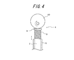
- FIG. 4 is a view similar to FIG. 3 showing a use state of the apparatus shown in FIG. 3.
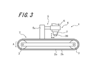
- An abrasion test apparatus 1 illustrated in FIG. 3 includes an endless annular polishing body 2 and a pair of polishing bodies wound around the polishing body 2 and rotated at least one of them by, for example, connecting to a motor (not shown).
- the test piece 20 made of rubber material or the like that forms the tread portion of the tire is held at the body roller 3 and the end portion on the polishing body 2 side, for example, and the test piece is against the flat surface portion on the outer peripheral side of the polishing body 2.
- test piece 20 is wound around the abrasive body roller 3 that is rotationally driven, and for example, the flat surface portion on the test piece 20 side of the abrasive body 2 that runs in the direction indicated by the arrow A in the figure.
- a reciprocating drive means 5 is disposed on the front side or the rear side in the traveling direction so as to be displaced at a required speed in parallel with the flat surface portion.
- the abrasive body 2 can be formed, for example, by adhering an abrasive cloth 2b or abrasive paper or other abrasive member over the entire outer peripheral surface of the endless annular rubber member 2a, or the rubber member 2a. It can also be formed by uniformly applying an abrasive such as crushed stone on the outer surface.
- the polishing member can be made of, for example, stainless steel, and can be formed of various materials as long as it can be attached to the outer peripheral surface of the rubber member 2a.
- "abrasive cloth” etc. here shall be based on JISK6264.
- the circumferential direction and width of the polishing body 2 are provided at a plurality of locations in the circumferential direction of the polishing body 2. It is preferable to provide a three-component force sensor (not shown) that measures the force in the three directions in the direction and the direction orthogonal to the outer peripheral surface of the polishing body 2.
- a three-component force sensor can be placed, for example, on the inner peripheral surface of the polishing body 2 or embedded in the polishing body 2, and each sensor uses, for example, a slip ring or the like. It is possible to connect to a measuring instrument (not shown) in a wired or wireless manner.
- the distance between the pair of polishing body rollers 3 is between them.
- a piston, a rack and pinion, a ball screw or the like (not shown) can be provided.
- the inner peripheral surface of the polishing body 2 is interposed between the pair of polishing body rollers 2 in order to suppress the bending or escape deformation of the polishing body 2 when the test piece 20 is pressed against the polishing body 2. It is also possible to provide one or a plurality of support rollers in contact with each other.
- the illustrated test piece holding means 4 includes a sleeve 6 attached to a frame (not shown) and a shaft that holds the test piece 20 at one end portion (lower end portion in the drawing) and slides and displaces inside the sleeve 6.
- the plate 8 as a cam follower attached to the member 7 and the other end portion (upper end portion in the figure) of the shaft member 7 and the plate 8 is urged and supported in the separating direction with respect to the opening peripheral edge of the sleeve 6.
- the coil spring 9 includes a cam 10 which is provided in contact with the plate 8 and is driven to rotate.
- the shaft member 7 together with the plate 8 spring-biased with respect to the sleeve 6 based on the rotation of the eccentric cam 10 driven to rotate around the axis is indicated by an arrow in the figure.
- the test piece 20 held on one end portion of the shaft member 7 is separated and moved closer to the polishing body 2 by being displaced vertically.
- a ball screw or a rack and pinion can be used as the holding means 4 for controlling the raising and lowering of the test piece. , Larger displacement can be performed with higher accuracy.
- this abrasion test apparatus 1 in a thermostat (not shown), it is possible to reproduce the temperature of the actual tire in use, and a heater (not shown) is also attached to the polishing body 2. Thus, the actual temperature condition of the road surface can be reproduced.
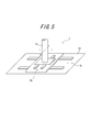
- the reciprocating drive means 5 is laid on a base 30 on which the apparatus 1 is installed, for example, as shown in a perspective view in FIG. 5, and extends in the traveling direction of the polishing body 2 or in a direction perpendicular to the traveling direction.
- the movable rail member 5b composed of a pair of rails and a support shaft 5a that travels on the movable rail member 5b by applying the same driving force and grips the test piece holding means 4 can be configured.
- a reciprocating drive means can also be comprised only by a pair of fixed rail extended in the running direction of the grinding
- the test piece 20 used in such an abrasion test apparatus 1 may be a rubber test piece prepared for testing in advance or a block test piece cut out from a tread portion of a tire.
- the dimension of the test piece 20 is 1 cm to 30 cm in the length (vertical direction) along the circumferential direction (left-right direction in FIG. 3) of the polishing body 2 in a state of being held by the test piece holding means 4. Further, the length (horizontal) along the width direction of the polishing body 2 (the front and back direction in FIG. 3) is set to 1 cm to 30 cm, and the direction orthogonal to the surface of the flat surface portion of the polishing body 2 (in FIG. 3).
- the thickness (height) in the direction along the (up and down direction) is preferably 3 mm to 30 mm, but it is also possible to use a test piece having a dimension outside these numerical ranges.
- a test piece 20 formed in a rectangular parallelepiped shape is held on the lower end portion of the test piece holding means 4, and
- the endless annular polishing body 2 is caused to travel in the circumferential direction, for example, as indicated by an arrow A in the drawing based on the application of a rotational driving force by a motor or the like to the polishing body roller 3.
- the abrasion test presses the test piece 20 against the flat surface portion on the outer peripheral side of the polishing body 2 with a required force based on the operation of the test piece holding means 4.
- the reciprocating drive means 5 causes the test piece 20 to be, for example, on the front side in the running direction of the flat surface portion at a required slip ratio with respect to the running speed of the polishing body 2.
- the test piece 20 is separated from the polishing body 2 and is displaced rearward in the running direction of the flat surface portion.
- the test piece 20 can be moved to the position at the start of the test.
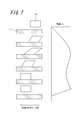
- the test piece 20 mainly adheres between the test piece 20 and the polishing body 2 as the flat surface portion of the polishing body 2 is pressed, as schematically shown in FIG.
- the circumferential shear stress gradually increases, but due to the displacement of the flat surface portion based on the reciprocating drive means 5 toward the front side in the traveling direction, the shear stress is once reduced and the specimen 20 is polished.
- a large shearing stress is applied based on a decrease in the relative speed with respect to the body 2, slipping occurs between the test piece 20 and the abrasive body 2 due to the separation operation of the test piece 20 by the test piece holding means 4.
- Directional shear stress will drop rapidly.
- the abrasion test apparatus 1 is used to polish the test piece 20 in a state where the relative speed of the test piece 20 to the polishing body 2 is 0, that is, the test piece 20 is pressed against the flat surface portion of the polishing body 2.
- a wear test can also be performed by displacing the body 2 at a constant speed.
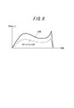
- the pressing force of the test piece 20 to the polishing body 2 or the test piece 20 By changing the relative speed with respect to the polishing body 2, it is possible to reproduce a shear stress as shown by a broken line in FIG.
- the traveling speed of the abrasive body 2 during the test is not particularly limited, but can be, for example, 0.1 km / h to 50 km / h, and in particular, 0.5 km / h to 35 km. It is preferable to set to / h in that a good wear characteristic evaluation by the wear test apparatus 1 becomes possible.
- the pressing force of the test piece 20 from the sensors to the polishing body 2, and the circumferential direction and width of the polishing body 2 are provided. Based on the measured values of the direction shear force, the circumferential shear stress when the test piece 20 is pressed against the polishing body 2 is shown in FIG.
- the pressing force of the test piece 20 on the polishing body 2 the displacement speed of the test piece 20, and the running speed of the polishing body 2 so as to obtain a waveform corresponding to Can be predicted with accuracy.
- FIG. 9 An example of such a control method is shown in the flowchart of FIG.
- the control method shown in FIG. 9 first, it is examined whether or not the measured value of the pressing force of the test piece 20 falls within a preset range, and if the measured value of the pressing force is out of this range, the test is performed. The pressing force by the piece holding means 5 is adjusted. On the other hand, if the measured value of the pressing force is within the set range, then, it is examined whether or not the measured value of the shearing force in the circumferential direction of the polishing body 2 falls within the preset range. When the measured value of the directional shear force is out of this range, the relative value of the displacement speed of the test piece 20 based on the reciprocating drive means 5 with respect to the traveling speed of the polishing body 2 is adjusted.
- the pressing force of the test piece 20 on the polishing body 2 and the circumferential shearing force of the test piece 20 can be controlled as expected. It is possible to faithfully reproduce the circumferential shear stress state in the ground contact surface at the time of load rolling of the tire.
- the reciprocating drive means 5 for causing the test piece 20 to directly move the test piece holding means 4 holding the test piece 20 in the traveling direction of the polishing body 2 is shown in FIG.
- the polishing body 2 can be displaced in a direction perpendicular to the traveling direction of the polishing body 2. According to this, since the test piece 20 can be moved left and right in the direction orthogonal to the traveling direction of the polishing body 2 when pressed against the polishing body 2, a slip angle is given by the wear test apparatus 1. Thus, it is possible to predict the wear of an actual tire that is loaded and rolled in a hot state.
- a plurality of three component force sensors provided in the circumferential direction of the polishing body 2, the pressing force of the test piece 20 to the polishing body 2, the displacement speed of the test piece 20, the traveling speed of the polishing body 2, and
- each of the moving speeds of the test piece 20 in the direction orthogonal to the traveling direction of the polishing body 2 for example, as illustrated in FIG. 10, first, as in the method shown in FIG. It is examined whether or not the measured values of the pressing force of 20 and the shearing force in the circumferential direction of the polishing body 2 are within a preset range, and when these measured values are both within the set range.
- the actual tires faithfully reproduce the circumferential and width direction shear stress state and the contact pressure state in the contact surface when a slip force is applied and a lateral force is applied. be able to.
Landscapes
- Physics & Mathematics (AREA)
- Health & Medical Sciences (AREA)
- Life Sciences & Earth Sciences (AREA)
- Chemical & Material Sciences (AREA)
- Analytical Chemistry (AREA)
- Biochemistry (AREA)
- General Health & Medical Sciences (AREA)
- General Physics & Mathematics (AREA)
- Immunology (AREA)
- Pathology (AREA)
- Tires In General (AREA)
- Investigating Strength Of Materials By Application Of Mechanical Stress (AREA)
Abstract
無端環状の研磨体(2)と、該研磨体(2)を巻き掛けられる、少なくとも一方を回転駆動可能とした一対の研磨体ローラ(3)と、弾性材料からなる試験片(20)を保持して、研磨体(2)の外周側の平坦面部分に対して試験片(20)を離隔および接近させる試験片保持手段(4)とを具えてなり、試験片(20)を研磨体(2)の前記平坦面部分に押圧して、試験片(20)の摩耗量を測定する摩耗試験装置(1)であって、前記試験片(20)を、回転駆動される研磨体ローラ(3)に巻き掛けた研磨体(2)の、試験片(20)を押圧する前記平坦面部分の走行方向の前方側および後方側へ、該平坦面部分と平行に変位させる往復駆動手段(5)を配設してなる。
Description
この発明は、タイヤの、たとえばトレッド部を構成するゴム材料等の弾性材料からなる試験片を、その試験片に対し相対変位する研磨体の平坦面上に押圧して、トレッドゴム試験片の摩耗量を、実際のタイヤと高い相関をもって測定する摩耗試験装置に関するものであり、具体的には、摩耗試験において、実際のタイヤの負荷転動に際する、接地面内での周方向および幅方向の剪断応力状態ならびに、接地圧状態の忠実なる再現を可能として、タイヤの摩耗を、高い精度で予測することのできる技術を提案するものである。
従来、この種の摩耗試験装置としては特許文献1、2に記載されたものがある。
特許文献1には、「少なくとも一方に駆動源を連結した一対のローラー間にベルト状の研摩体を装架し、該研摩体の平面に対して試料を押圧する試料支持機構を設置した摩耗試験装置」が開示されており、この摩耗試験装置によれば、「試料としてタイヤトレッドを構成するゴム試料を使用した場合にタイヤ走行時の摩耗を正確にシミュレーションすることができる。」としている。
特許文献1には、「少なくとも一方に駆動源を連結した一対のローラー間にベルト状の研摩体を装架し、該研摩体の平面に対して試料を押圧する試料支持機構を設置した摩耗試験装置」が開示されており、この摩耗試験装置によれば、「試料としてタイヤトレッドを構成するゴム試料を使用した場合にタイヤ走行時の摩耗を正確にシミュレーションすることができる。」としている。
また、特許文献2には、「砥石または擬似路面にゴム試験片を押し付けて、該ゴム試験片の試験を行うゴム試験機であって、前記ゴム試験片を前記砥石または擬似路面に対し変位させて、前記ゴム試験片に、前記砥石または擬似路面に対する粘着および/またはすべりを与えることを特徴とする」ものが記載されており、この装置によれば、「タイヤなどの実際の製品が摩耗する際のゴムの挙動を精度良く再現することができ、これにより、測定されるゴム摩耗度を、実際の摩耗結果に精度よく対応させることの可能なゴム試験機を実現することが可能となった。」とする。
しかるに、特許文献1、2に記載されたいずれの装置においても、たとえば水平方向に移動する「研摩体」ないしは「砥石または擬似路面」に対して、「ゴム試験片」等を、上下方向にのみ変位させて押圧することから、実際に路面上を負荷転動するタイヤの、トレッド接地面の摩耗を、十分に高い精度で予測することができなかった。
この発明は、従来技術の抱えるこのような問題を解決することを課題とするものであり、それの目的とするところは、タイヤの負荷転動時における接地面での周方向および幅方向剪断応力ならびに、接地圧状況を忠実に再現することができ、それにより、高い精度で、タイヤの摩耗の予測を可能とする摩耗試験装置を提供するにある。
発明者は、タイヤの負荷転動時の、トレッド接地面内の微小要素への力および滑りの作用に着目し、その微小要素には、接地圧とともに、路面に対するゴム材料の粘着および滑りによる剪断力が作用するとの前提の下で、タイヤの陸部の踏込みから蹴出しまでの間で、接地面内の微小要素に作用する剪断力が、時間の経過に伴って、図1にグラフで示す如く変化することを見出した。
すなわち、図2に模式図で示すように、たとえば、図に矢印で示す向きに自由転動するタイヤ100のトレッドブロックは、踏込み位置101aに達した際に、主として、路面110との粘着に基く大きな剪断応力を受けるが、その後、剪断応力は、荷重直下の位置101bまで減少し、蹴出し位置101cに向かうに従って逆方向に増加していき、そして、蹴出し位置101cに達したところで、トレッドブロックには、路面110との間で滑りが生じて、瞬間的に大きな剪断応力が作用する一方で、トレッドブロックの接地面からの解放によって、周方向剪断応力は急激に低下することになる。
なおここで、空気入りタイヤでは、接地圧の作用によって、トレッド接地面が押込み変形させられることから、踏込み位置101aと蹴出し位置101cとの間では、トレッドブロックは路面に対して実質的に平行に接触することになる。
なおここで、空気入りタイヤでは、接地圧の作用によって、トレッド接地面が押込み変形させられることから、踏込み位置101aと蹴出し位置101cとの間では、トレッドブロックは路面に対して実質的に平行に接触することになる。
従って、トレッドゴム材料の試験片を用いた摩耗試験に当っては、図1に示す剪断応力状態を忠実に再現することで、路面を負荷転動するタイヤのトレッド接地面の摩耗度を、実際のタイヤと高い相関をもって、精度良く予測することができると考えた。
このような知見に基き、この発明の摩耗試験装置は、無端環状の研磨体と、該研磨体を巻き掛けられて、少なくとも一方を回転駆動可能とした一対の研磨体ローラと、弾性材料からなる試験片を保持して、研磨体の外周側の平坦面部分に対して試験片を離隔および接近させる試験片保持手段とを具えてなり、試験片を研磨体の前記平坦面部分に押圧して、試験片の摩耗量を測定するものであって、前記試験片に、回転駆動される研磨体ローラに巻き掛けた研磨体の、試験片を押圧する前記平坦面部分の走行方向の前方側および後方側への、該平坦面部分と平行な変位をもたらす往復駆動手段を配設してなるものである。
ここで、前記往復駆動手段は、試験片の、前記平坦面部分の走行方向への変位のみならず、試験片の、平坦面部分の走行方向に直交する方向への、前記平坦面部分と平行な変位をも可能に構成することが好ましい。
なお好ましくは、前記研磨体の周方向の複数個所に、該研磨体の周方向および幅方向、ならびに、研磨体の外周面に直交する方向の3方向の力を測定する3分力センサを取り付け、たとえば、前記3分力センサによる測定値に基き、研磨体ローラの回転速度と、試験片保持手段による、研磨体の前記平坦面部分に対する試験片の押圧力と、往復駆動手段による、試験片の変位速度とをフィードバック制御する制御手段を設ける。
この発明の摩耗試験装置によれば、一対の研磨体ローラに巻き掛けられる、周方向に走行駆動可能とした無端状研磨体の外周面の平坦面部分に、試験片保持手段によって、試験片を押圧するとともに、試験片を研磨体上に押圧した状態で、往復駆動手段の作動に基き、試験片を、前記平坦面部分の走行方向の前方側もしくは後方側に向けて、たとえば、研磨体の走行速度に対して所要の相対速度で変位させ、しかる後に、試験片を研磨体の外周面から離隔させることにより、試験片の、研磨体上への押圧力および、試験片の、研磨体の平坦面部分に対する相対変位速度のそれぞれの制御の下で、上述したような、実際のタイヤの、路面に対する踏込みから蹴出しまでの間の接地面での周方向剪断応力状態を忠実に再現できるので、タイヤの摩耗を高い精度で予測することができる。
なお、この摩耗試験装置によれば、研磨体を、走行駆動される無端環状としたことにより、試験片が、研磨体の外周面で摩耗されることによって生じる摩耗粉は、試験片が押圧される研磨体の走行方向の前方に運ばれることになり、ブラシ等によって、これを容易に除去することができるので、前記摩耗粉が、試験片の摩耗状況に及ぼす影響を確実に取り除くことができる。
ここで、往復駆動手段を、試験片の、平坦面部分の走行方向と直交する方向への、前記平坦面部分と平行な変位をも可能に構成したときは、実際のタイヤで、スリップアングルを付与して横力が作用した際の、接地面内での周方向および幅方向剪断応力状態ならびに、接地圧状態を忠実に再現することができる。
ここにおいて、研磨体の周方向の複数個所に3分力センサを取り付けたときは、試験片が研磨体から受ける各方向の応力を、リアルタイムで測定することができ、そして、かかる測定値を用いて、試験片の、研磨体への押圧力および、試験片の、研磨体に対する相対速度のそれぞれをフィードバック制御することで、タイヤの負荷転動時における、接地面での周方向剪断応力の発生状況のより忠実なる再現および、試験条件の所要に応じた変更が可能となる。
以下に図面を参照しつつ、この発明の実施の形態について説明する。
図3に例示する摩耗試験装置1は、無端環状の研磨体2と、研磨体2を巻き掛けられて、少なくとも一方を、たとえば、図示しないモータに連結すること等によって回転駆動される一対の研磨体ローラ3と、研磨体2側の端部分で、たとえば、タイヤのトレッド部を形成するゴム材料等の試験片20を保持して、研磨体2の外周側の平坦面部分に対して試験片20を離隔および接近させる試験片保持手段4とを具える。
図3に例示する摩耗試験装置1は、無端環状の研磨体2と、研磨体2を巻き掛けられて、少なくとも一方を、たとえば、図示しないモータに連結すること等によって回転駆動される一対の研磨体ローラ3と、研磨体2側の端部分で、たとえば、タイヤのトレッド部を形成するゴム材料等の試験片20を保持して、研磨体2の外周側の平坦面部分に対して試験片20を離隔および接近させる試験片保持手段4とを具える。
そしてここでは、試験片20を、回転駆動される研磨体ローラ3に巻き掛けられて、たとえば、図に矢印Aで示す向きに走行される研磨体2の、試験片20側の平坦面部分の走行方向の前方側もしくは後方側へ、その平坦面部分と平行に、所要の速度で変位させる往復駆動手段5を配設する。
ここで、研磨体2は、たとえば、無端環状のゴム部材2aの外周面の全周にわたって、研磨布2bもしくは研磨紙その他の研磨部材を貼着させることにより形成することができる他、ゴム部材2aの外表面に、粉砕石等の研磨材を均一に塗布すること等によっても形成することができる。
この研磨部材は、たとえばステンレス製とすることも可能であり、ゴム部材2aの外周面に貼り付けることができるものであれば、種々の材料にて形成することができる。
なお、ここでいう「研磨布」等は、JIS K6264に準拠するものとする。
この研磨部材は、たとえばステンレス製とすることも可能であり、ゴム部材2aの外周面に貼り付けることができるものであれば、種々の材料にて形成することができる。
なお、ここでいう「研磨布」等は、JIS K6264に準拠するものとする。
ここにおいて、後述する摩耗試験を行うに際し、試験片20の、研磨体2への押圧力等をフィードバック制御するため、研磨体2の周方向の複数個所には、研磨体2の周方向および幅方向、ならびに、研磨体2の外周面に直交する方向の3方向の力を測定する、図示しない3分力センサを設けることが好ましい。
かかる3分力センサは、たとえば、研磨体2の内周面に貼り付けるか、または、研磨体2の内部に埋め込んで配置することができ、そして、各センサは、たとえば、スリップリング等を用いて有線で、または無線で、図示しない計測器に連結することができる。
かかる3分力センサは、たとえば、研磨体2の内周面に貼り付けるか、または、研磨体2の内部に埋め込んで配置することができ、そして、各センサは、たとえば、スリップリング等を用いて有線で、または無線で、図示しない計測器に連結することができる。
またここで、研磨体2を研磨体ローラ3に巻き掛けた後に、その研磨体2に所要の張力を付与することを目的として、一対の研磨体ローラ3間には、それらの相互間の距離を調整する、図示しないピストン、ラックアンドピニオン、ボールねじ等を設けることができる。
なお、図示は省略するが、試験片20を研磨体2に押し付けた際の、研磨体2の撓みないしは逃げ変形を抑制するべく、一対の研磨体ローラ2間に、研磨体2の内周面に接触する一個もしくは複数個の支持ローラを設けることもできる。
なお、図示は省略するが、試験片20を研磨体2に押し付けた際の、研磨体2の撓みないしは逃げ変形を抑制するべく、一対の研磨体ローラ2間に、研磨体2の内周面に接触する一個もしくは複数個の支持ローラを設けることもできる。
ところで、研磨体2の外周側の平坦面部分に対して、試験片20を離隔および接近させる試験片保持手段4としては、たとえば、図4に要部を拡大断面図で例示するカム機構を用いることができる。
すなわち、図示の試験片保持手段4は、図示しないフレームに取り付けたスリーブ6と、一方の端部分(図では下端部分)で試験片20を保持して、スリーブ6の内側で摺動変位する軸部材7と、軸部材7の他方の端部分(図では上端部分)に取り付けた、カム従節としてのプレート8と、スリーブ6の開口周縁部に対してプレート8を離隔方向に付勢支持するコイルスプリング9と、プレート8に当接させて設けられ、回転駆動されるカム10とからなる。
すなわち、図示の試験片保持手段4は、図示しないフレームに取り付けたスリーブ6と、一方の端部分(図では下端部分)で試験片20を保持して、スリーブ6の内側で摺動変位する軸部材7と、軸部材7の他方の端部分(図では上端部分)に取り付けた、カム従節としてのプレート8と、スリーブ6の開口周縁部に対してプレート8を離隔方向に付勢支持するコイルスプリング9と、プレート8に当接させて設けられ、回転駆動されるカム10とからなる。
この試験片保持手段4によれば、軸周りで回転駆動される偏芯カム10の回動に基き、軸部材7が、スリーブ6に対してばね付勢されたプレート8とともに、図に矢印で示すように上下変位することで、軸部材7の一方の端部分に保持させた試験片20が、研磨体2に対して離隔および接近変位することになる。
なお、かかる試験片保持手段4のカム機構に変えて、図示は省略するが、ボールねじもしくは、ラックアンドピニオン等を、試験片の昇降駆動を司る保持手段4として用いることもでき、この場合は、より大きな変位をより高い精度で行わせることができる。
なお、かかる試験片保持手段4のカム機構に変えて、図示は省略するが、ボールねじもしくは、ラックアンドピニオン等を、試験片の昇降駆動を司る保持手段4として用いることもでき、この場合は、より大きな変位をより高い精度で行わせることができる。
そして、この摩耗試験装置1を、図示しない恒温槽内に設置することで、実際のタイヤの使用状態での気温を再現することができ、また、研磨体2に、これも図示しないヒータを取り付けることによって、実際の路面の温度状況を再現することができる。
また、往復駆動手段5は、たとえば、図5に斜視図で示すように、装置1を設置する土台30上に敷設されて、研磨体2の走行方向もしくは、その走行方向と直交する方向に延びる一対の固定レール5cと、図示しないサーボモータもしくはエア圧等による駆動力の付与に基き、固定レール5c上を走行するプレートおよび、そのプレート上に敷設されて、固定レール5cに直交する向きに延びる一対のレールからなる可動レール部材5bと、同様の駆動力の付与によって可動レール部材5b上を走行するとともに、前記試験片保持手段4を把持する支持軸5aとで構成することができる。
なお、図示は省略するが、往復駆動手段は、前述したような、研磨体2の走行方向に延びる一対の固定レールおよび、その固定レール上を走行する支持軸だけで構成することもできる。
なお、図示は省略するが、往復駆動手段は、前述したような、研磨体2の走行方向に延びる一対の固定レールおよび、その固定レール上を走行する支持軸だけで構成することもできる。
このような摩耗試験装置1に用いる試験片20は、予め試験用に作成したゴム試験片であっても、タイヤのトレッド部から切り出したブロック試験片であっても良い。かかる試験片20の寸法は、上記の試験片保持手段4に保持させた状態で、研磨体2の周方向(図3では左右方向)に沿う向きの長さ(縦)を1cm~30cmとし、また、研磨体2の幅方向(図3では紙面の表裏方向)に沿う向きの長さ(横)を1cm~30cmとし、そして、研磨体2平坦面部分の表面に直交する方向(図3では上下方向)に沿う向きの厚み(高さ)を3mm~30mmとすることが好ましいが、それらの各数値範囲から外れる寸法の試験片を用いることも可能である。
以上に述べた摩耗試験装置1で摩耗試験を行うには、はじめに、図3に示すように、たとえば直方体状に形成した試験片20を、試験片保持手段4の下端部分に保持させ、また、無端環状の研磨体2を、研磨体ローラ3への、モータ等による回転駆動力の付与に基き、周方向へ、たとえば図に矢印Aで示すように走行させる。
そして、摩耗試験は、図6に例示するように、試験片保持手段4の作動に基き、研磨体2の外周側の平坦面部分に、試験片20を所要の力で押圧するとともに、平坦面部分に試験片20を押圧した状態で、往復駆動手段5によって、試験片20を、たとえば、前記平坦面部分の走行方向の前方側に、研磨体2の走行速度に対し、所要のスリップ率で変位させ、しかる後、試験片保持手段4および往復駆動手段5のそれぞれの作動に基き、試験片20を、研磨体2から離隔させるとともに、前記平坦面部分の走行方向の後方側に変位させて、試験片20を試験開始時の位置まで移動させることにより行うことができる。
ここにおいて、上記の摩耗試験では、試験片20は、図7に模式的に示すように、研磨体2の平坦面部分への押圧に伴い、主として試験片20と研磨体2との間の粘着に起因して、周方向剪断応力が次第に増大するが、往復駆動手段5に基く平坦面部分の走行方向の前方側への変位によって、剪断応力は一旦減少し、そして、試験片20の、研磨体2に対する相対速度の低下に基く、大きな剪断応力が作用した後に、試験片保持手段4による、試験片20の離隔作動によって、試験片20と研磨体2との間で滑りが生じて、周方向剪断応力が急激に低下することになる。
すなわち、摩耗試験装置1を用いて行う上記の摩耗試験によれば、図1に例示したような、実際のタイヤの接地面での周方向剪断応力状態を極めて忠実に再現することができ、その結果として、タイヤの摩耗を、高い精度で予測することができる。
なおここで、摩耗試験装置1を用いて、試験片20の、研磨体2に対する相対速度が0、つまり、研磨体2の平坦面部分に試験片20を押圧した状態で、試験片20を研磨体2と等速で変位させることで、摩耗試験を行うこともできる。
また、一の試験で、試験片20の、研磨体2への押圧を複数回行う場合において、その試験の途中で、試験片20の、研磨体2への押圧力や、試験片20の、研磨体2に対する相対速度を変化させることにより、図8に破線で示すような剪断応力を再現することも可能である。
そしてまた、試験に際する研磨体2の走行速度は、とくに限定されるものではないが、たとえば0.1km/h~50km/hとすることができ、なかでも、0.5km/h~35km/hに設定することが、摩耗試験装置1による良好な摩耗特性評価が可能になる点で好ましい。
また、一の試験で、試験片20の、研磨体2への押圧を複数回行う場合において、その試験の途中で、試験片20の、研磨体2への押圧力や、試験片20の、研磨体2に対する相対速度を変化させることにより、図8に破線で示すような剪断応力を再現することも可能である。
そしてまた、試験に際する研磨体2の走行速度は、とくに限定されるものではないが、たとえば0.1km/h~50km/hとすることができ、なかでも、0.5km/h~35km/hに設定することが、摩耗試験装置1による良好な摩耗特性評価が可能になる点で好ましい。
そして、研磨体2の周方向に複数の3分力センサを設けた場合は、それらのセンサからの、試験片20の、研磨体2への押圧力、ならびに、研磨体2の周方向および幅方向の剪断力のそれぞれの測定値に基き、試験片20の、研磨体2への押圧時の周方向剪断応力が、図1に示す、実際のタイヤの接地面が路面から受ける周方向剪断応力と対応する波形となるように、試験片20の、研磨体2への押圧力、試験片20の変位速度および、研磨体2の走行速度を制御することにより、タイヤの摩耗を、より一層高い精度の下で予測することができる。
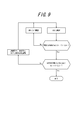
かかる制御方法の一例を、図9にフローチャートで示す。
図9に示す制御方法では、はじめに、試験片20の押圧力の測定値が、予め設定した範囲内に入るか否かを検討して、押圧力の測定値がこの範囲から外れる場合は、試験片保持手段5による押圧力を調整する。
一方、前記押圧力の測定値が、設定範囲内である場合は、次いで、研磨体2の周方向の剪断力の測定値が、予め設定した範囲内に入るか否かを検討して、周方向剪断力の測定値がこの範囲内から外れる場合は、往復駆動手段5に基く試験片20の変位速度の、研磨体2の走行速度に対する相対値を調整する。
図9に示す制御方法では、はじめに、試験片20の押圧力の測定値が、予め設定した範囲内に入るか否かを検討して、押圧力の測定値がこの範囲から外れる場合は、試験片保持手段5による押圧力を調整する。
一方、前記押圧力の測定値が、設定範囲内である場合は、次いで、研磨体2の周方向の剪断力の測定値が、予め設定した範囲内に入るか否かを検討して、周方向剪断力の測定値がこの範囲内から外れる場合は、往復駆動手段5に基く試験片20の変位速度の、研磨体2の走行速度に対する相対値を調整する。
このことにより、試験片20の、研磨体2への押圧力、ならびに、試験片20の周方向剪断力を、所期したとおりに制御できるので、装置1によって、図1に示すような、実際のタイヤの負荷転動に際する、接地面内での周方向剪断応力状態を忠実に再現することができる。
ところで、試験片20、直接的にはこれを保持させた試験片保持手段4の、研磨体2の走行方向への変位をもたらす往復駆動手段5は、図5に示すように、試験片20を、研磨体2の走行方向に直交する方向にも変位させることができるように構成することが好ましい。
このことによれば、試験片20を、研磨体2への押圧に際して、研磨体2の走行方向と直交する方向に左右に移動させることができるので、摩耗試験装置1によって、スリップアングルが付与された状態で負荷転動する実際のタイヤの摩耗を予測することが可能となる。
このことによれば、試験片20を、研磨体2への押圧に際して、研磨体2の走行方向と直交する方向に左右に移動させることができるので、摩耗試験装置1によって、スリップアングルが付与された状態で負荷転動する実際のタイヤの摩耗を予測することが可能となる。
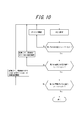
この場合、研磨体2の周方向に複数個設けた3分力センサで、試験片20の、研磨体2への押圧力、試験片20の変位速度および、研磨体2の走行速度、ならびに、試験片20の、研磨体2の走行方向に直交する方向への移動速度のそれぞれを制御するには、たとえば、図10に例示するように、はじめに、図9に示す方法と同様に、試験片20の押圧力および、研磨体2の周方向の剪断力のそれぞれの測定値が、予め設定した範囲内に入るか否かを検討し、これらの測定値がいずれも設定範囲内である場合は、次いで、研磨体2の幅方向の剪断力の測定値が設定範囲内であるか否かを検討する。
この幅方向剪断力の測定値が設定範囲から外れる場合は、試験片20の、研磨体2の走行方向と直交する方向への移動速度を調整する。
この幅方向剪断力の測定値が設定範囲から外れる場合は、試験片20の、研磨体2の走行方向と直交する方向への移動速度を調整する。
かかる制御方法を用いることにより、実際のタイヤで、スリップアングルを付与して横力が作用した際の、接地面内での周方向および幅方向剪断応力状態ならびに、接地圧状態を忠実に再現することができる。
1 摩耗試験装置
2 研磨体
2a ゴム部材
2b 研磨布
3 研磨体ローラ
4 試験片保持手段
5 往復駆動手段
5a 支持軸
5b 可動レール部材
5c 固定レール
6 スリーブ
7 軸部材
8 プレート
9 コイルスプリング
10 カム
20 試験片
2 研磨体
2a ゴム部材
2b 研磨布
3 研磨体ローラ
4 試験片保持手段
5 往復駆動手段
5a 支持軸
5b 可動レール部材
5c 固定レール
6 スリーブ
7 軸部材
8 プレート
9 コイルスプリング
10 カム
20 試験片
Claims (3)
- 無端環状の研磨体と、該研磨体を巻き掛けられる、少なくとも一方を回転駆動可能とした一対の研磨体ローラと、弾性材料からなる試験片を保持して、研磨体の外周側の平坦面部分に対して試験片を離隔および接近させる試験片保持手段とを具えてなり、試験片を研磨体の前記平坦面部分に押圧して、試験片の摩耗量を測定する摩耗試験装置であって、
前記試験片を、回転駆動される研磨体ローラに巻き掛けた研磨体の、試験片を押圧する前記平坦面部分の走行方向の前方側および後方側へ、該平坦面部分と平行に変位させる往復駆動手段を配設してなる摩耗試験装置。 - 前記往復駆動手段を、試験片の、前記平坦面部分の走行方向に直交する方向への、平坦面部分と平行な変位を可能に構成してなる請求項1に記載の摩耗試験装置。
- 前記研磨体の周方向の複数個所に、該研磨体の周方向および幅方向、ならびに、研磨体の外周面に直交する方向の3方向の力を測定する3分力センサを取り付けてなる請求項1もしくは2に記載の摩耗試験装置。
Applications Claiming Priority (2)
| Application Number | Priority Date | Filing Date | Title |
|---|---|---|---|
| JP2011-069948 | 2011-03-28 | ||
| JP2011069948A JP2012202926A (ja) | 2011-03-28 | 2011-03-28 | 摩耗試験装置 |
Publications (1)
| Publication Number | Publication Date |
|---|---|
| WO2012132226A1 true WO2012132226A1 (ja) | 2012-10-04 |
Family
ID=46930022
Family Applications (1)
| Application Number | Title | Priority Date | Filing Date |
|---|---|---|---|
| PCT/JP2012/001349 Ceased WO2012132226A1 (ja) | 2011-03-28 | 2012-02-28 | 摩耗試験装置 |
Country Status (2)
| Country | Link |
|---|---|
| JP (1) | JP2012202926A (ja) |
| WO (1) | WO2012132226A1 (ja) |
Cited By (2)
| Publication number | Priority date | Publication date | Assignee | Title |
|---|---|---|---|---|
| CN111879646A (zh) * | 2015-04-30 | 2020-11-03 | 横滨橡胶株式会社 | 刮痕磨耗试验装置以及方法 |
| CN119290646A (zh) * | 2024-12-11 | 2025-01-10 | 北京市产品质量监督检验研究院 | 一种模拟复杂环境中箱包行走轮磨耗试验设备 |
Families Citing this family (2)
| Publication number | Priority date | Publication date | Assignee | Title |
|---|---|---|---|---|
| CN104596920A (zh) * | 2015-02-13 | 2015-05-06 | 吉林大学 | 一种带传动式橡胶摩擦特性测试系统 |
| CN110567826A (zh) * | 2018-06-06 | 2019-12-13 | 安徽省宁国市宁星耐磨材料有限公司 | 耐磨材料试验机及其试验方法 |
Citations (3)
| Publication number | Priority date | Publication date | Assignee | Title |
|---|---|---|---|---|
| JPH01292232A (ja) * | 1988-05-20 | 1989-11-24 | Bridgestone Corp | 摩擦摩耗試験機 |
| JPH11173952A (ja) * | 1997-12-10 | 1999-07-02 | T & T:Kk | タイヤ試験装置 |
| JP2007139708A (ja) * | 2005-11-22 | 2007-06-07 | Toyo Tire & Rubber Co Ltd | タイヤ摩耗試験方法 |
-
2011
- 2011-03-28 JP JP2011069948A patent/JP2012202926A/ja not_active Withdrawn
-
2012
- 2012-02-28 WO PCT/JP2012/001349 patent/WO2012132226A1/ja not_active Ceased
Patent Citations (3)
| Publication number | Priority date | Publication date | Assignee | Title |
|---|---|---|---|---|
| JPH01292232A (ja) * | 1988-05-20 | 1989-11-24 | Bridgestone Corp | 摩擦摩耗試験機 |
| JPH11173952A (ja) * | 1997-12-10 | 1999-07-02 | T & T:Kk | タイヤ試験装置 |
| JP2007139708A (ja) * | 2005-11-22 | 2007-06-07 | Toyo Tire & Rubber Co Ltd | タイヤ摩耗試験方法 |
Cited By (2)
| Publication number | Priority date | Publication date | Assignee | Title |
|---|---|---|---|---|
| CN111879646A (zh) * | 2015-04-30 | 2020-11-03 | 横滨橡胶株式会社 | 刮痕磨耗试验装置以及方法 |
| CN119290646A (zh) * | 2024-12-11 | 2025-01-10 | 北京市产品质量监督检验研究院 | 一种模拟复杂环境中箱包行走轮磨耗试验设备 |
Also Published As
| Publication number | Publication date |
|---|---|
| JP2012202926A (ja) | 2012-10-22 |
Similar Documents
| Publication | Publication Date | Title |
|---|---|---|
| KR102396601B1 (ko) | 고무 마모를 측정하기 위한 장치 | |
| AU2016253804B2 (en) | Abrasive wear test device and method | |
| JP5035991B2 (ja) | ゴム試験機 | |
| KR101414991B1 (ko) | 타이어 트레드 마모 시험 장비에 대한 측방향 위치 제어 | |
| CN102954920B (zh) | 用于评估轮胎胎面部耐磨性的方法 | |
| JP4963978B2 (ja) | ゴム摩耗試験機、および、それを用いたタイヤトレッド用ゴムの摩耗試験方法 | |
| JP5534587B2 (ja) | ゴム試験機 | |
| JP2014190945A (ja) | ゴム摩耗試験方法及びゴム摩耗試験装置 | |
| JP2012202926A (ja) | 摩耗試験装置 | |
| WO2010018735A1 (ja) | 更生タイヤの製造方法及び使用済みタイヤの研削装置 | |
| JP3997647B2 (ja) | 摩耗試験装置 | |
| CN111566254B (zh) | 地面及与其相关的设备和方法 | |
| CN109313111B (zh) | 橡胶的磨耗试验装置 | |
| JP6045390B2 (ja) | ゴム摩耗試験方法 | |
| JP5478464B2 (ja) | 摩耗試験装置 | |
| JP5297844B2 (ja) | ゴム試験機用円盤状ゴム試験片およびそれを用いたゴム試験機 | |
| JP5534586B2 (ja) | ゴム試験機およびゴム試験方法 | |
| JP2001337032A (ja) | 弾性材料の摩擦特性試験方法および装置 | |
| JP2011153865A (ja) | ゴム試験機及びこれを用いたゴム試験方法 | |
| JP2006242697A (ja) | 摩耗試験方法および摩耗試験装置 | |
| KR101907495B1 (ko) | 압전 박막을 이용한 타이어 평가 장치 | |
| KR101899216B1 (ko) | 타이어 트레드 고무의 제동성능 시험장치 | |
| JP6319841B2 (ja) | ゴム付着の評価方法 | |
| KR102105416B1 (ko) | 공기입 타이어의 마모 수명 예측 방법 | |
| JP2014066553A (ja) | 摩耗試験方法及び摩耗試験装置 |
Legal Events
| Date | Code | Title | Description |
|---|---|---|---|
| 121 | Ep: the epo has been informed by wipo that ep was designated in this application |
Ref document number: 12764054 Country of ref document: EP Kind code of ref document: A1 |
|
| NENP | Non-entry into the national phase |
Ref country code: DE |
|
| 122 | Ep: pct application non-entry in european phase |
Ref document number: 12764054 Country of ref document: EP Kind code of ref document: A1 |