WO2012132097A1 - Rotary damper - Google Patents
Rotary damper Download PDFInfo
- Publication number
- WO2012132097A1 WO2012132097A1 PCT/JP2011/076538 JP2011076538W WO2012132097A1 WO 2012132097 A1 WO2012132097 A1 WO 2012132097A1 JP 2011076538 W JP2011076538 W JP 2011076538W WO 2012132097 A1 WO2012132097 A1 WO 2012132097A1
- Authority
- WO
- WIPO (PCT)
- Prior art keywords
- flow path
- rotor
- check valve
- case
- pressure regulating
- Prior art date
Links
Images


Classifications
-
- F—MECHANICAL ENGINEERING; LIGHTING; HEATING; WEAPONS; BLASTING
- F16—ENGINEERING ELEMENTS AND UNITS; GENERAL MEASURES FOR PRODUCING AND MAINTAINING EFFECTIVE FUNCTIONING OF MACHINES OR INSTALLATIONS; THERMAL INSULATION IN GENERAL
- F16F—SPRINGS; SHOCK-ABSORBERS; MEANS FOR DAMPING VIBRATION
- F16F9/00—Springs, vibration-dampers, shock-absorbers, or similarly-constructed movement-dampers using a fluid or the equivalent as damping medium
- F16F9/10—Springs, vibration-dampers, shock-absorbers, or similarly-constructed movement-dampers using a fluid or the equivalent as damping medium using liquid only; using a fluid of which the nature is immaterial
- F16F9/14—Devices with one or more members, e.g. pistons, vanes, moving to and fro in chambers and using throttling effect
- F16F9/145—Devices with one or more members, e.g. pistons, vanes, moving to and fro in chambers and using throttling effect involving only rotary movement of the effective parts
-
- B—PERFORMING OPERATIONS; TRANSPORTING
- B60—VEHICLES IN GENERAL
- B60N—SEATS SPECIALLY ADAPTED FOR VEHICLES; VEHICLE PASSENGER ACCOMMODATION NOT OTHERWISE PROVIDED FOR
- B60N2/00—Seats specially adapted for vehicles; Arrangement or mounting of seats in vehicles
- B60N2/02—Seats specially adapted for vehicles; Arrangement or mounting of seats in vehicles the seat or part thereof being movable, e.g. adjustable
- B60N2/22—Seats specially adapted for vehicles; Arrangement or mounting of seats in vehicles the seat or part thereof being movable, e.g. adjustable the back-rest being adjustable
- B60N2/2227—Seats specially adapted for vehicles; Arrangement or mounting of seats in vehicles the seat or part thereof being movable, e.g. adjustable the back-rest being adjustable and provided with braking systems
-
- B—PERFORMING OPERATIONS; TRANSPORTING
- B60—VEHICLES IN GENERAL
- B60N—SEATS SPECIALLY ADAPTED FOR VEHICLES; VEHICLE PASSENGER ACCOMMODATION NOT OTHERWISE PROVIDED FOR
- B60N2/00—Seats specially adapted for vehicles; Arrangement or mounting of seats in vehicles
- B60N2/90—Details or parts not otherwise provided for
- B60N2/919—Positioning and locking mechanisms
- B60N2/933—Positioning and locking mechanisms rotatable
- B60N2/938—Positioning and locking mechanisms rotatable and provided with braking systems
Definitions
- the present invention relates to a rotary damper, and more particularly to a structure suitable for a unidirectional rotary damper.
- Patent Document 1 discloses a unidirectional rotary damper that has a simple structure and can be manufactured at low cost.
- a rotary damper disclosed in Patent Document 1 includes a case having a cylindrical chamber, and a cylindrical rotor body and vanes that are housed in the cylindrical chamber so that the center line of the cylindrical chamber and the rotation axis are rotatable. And a viscous fluid filled in the cylindrical chamber, and a lid for containing the rotor together with the viscous fluid in the cylindrical chamber.
- a convex partition toward the center line is formed on the inner wall surface of the cylindrical chamber so as to form a slight gap with the outer peripheral surface of the rotor body.
- the vane is formed to protrude from the outer peripheral surface of the rotor body toward the inner peripheral surface of the cylindrical chamber so as to form a slight gap with the inner peripheral surface of the cylindrical chamber.
- the vane is formed with a flow path connecting from one side surface (referred to as a first side surface) perpendicular to the rotation direction of the rotor to the other side surface (referred to as a second side surface).
- a seal member that fills a gap between the vane and the inner wall surface of the cylindrical chamber is attached to the tip surface of the vane (a surface facing the inner wall surface of the cylindrical chamber).
- the seal member includes an elastic check valve that opens and closes the flow path from the second side surface in the vane rotation direction.
- the rotary damper disclosed in Patent Document 1 is configured such that when a force that rotates the vane in the direction from the first side surface to the second side surface (forward rotation direction) is applied to the rotor, the viscosity in the cylindrical chamber is increased.
- the check valve is pressed against the second side surface of the vane by the fluid, and the flow path is blocked by the check valve.
- the movement of the viscous fluid is limited only through a slight gap between the partition of the cylindrical chamber and the outer peripheral surface of the rotor body, and the pressure on the viscous fluid on the second side surface side of the vane is increased. Strong braking torque is generated.
- the present invention has been made in view of the above circumstances, and an object of the present invention is to provide a technique capable of reducing the possibility that the rotary damper will be damaged even when a rotational force more than expected is applied.
- the present invention provides a rotary damper that generates braking torque with respect to an applied rotational force by restricting the movement of the filled viscous fluid.
- means for releasing the restriction on the movement of the viscous fluid is provided.
- the present invention is a rotary damper that generates a braking torque with respect to an applied rotational force by limiting movement of a filled viscous fluid,
- a pressure regulating valve that is opened when the rotational force is equal to or greater than a predetermined value and releases the restriction on the movement of the viscous fluid.
- the rotary damper A case comprising a cylindrical chamber filled with the viscous fluid; A rotor accommodated in the cylindrical chamber so as to rotate relative to the case around a center line of the cylindrical chamber; A check valve that opens and closes depending on the rotation direction of the rotor, On the side wall surface of the cylindrical chamber, A convex partition is formed along the center line of the cylindrical chamber so that the front end surface is close to the outer peripheral surface of the rotor, On the outer peripheral surface of the rotor, A vane whose tip surface is close to the side wall surface of the cylindrical chamber is formed, The check valve is Closed against relative rotation of the rotor in the forward rotation direction with respect to the case, restricts the movement of the viscous fluid between regions partitioned by the partition and the vane, while reversing the rotor with respect to the case Allowing movement of the viscous fluid between regions partitioned by the partition and the vane, open to relative rotation in a direction; The pressure regulating valve is When the rotational force applied to rotate the rot
- the pressure on the viscous fluid filled in the cylindrical chamber can be suppressed to a predetermined value or less, so that the possibility that the rotary damper is damaged can be reduced.
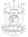
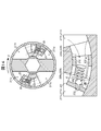
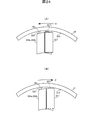
- FIG. 1A and FIG. 1B are an external view and a partial sectional view showing a schematic configuration of a rotary damper 1 according to the first embodiment of the present invention.
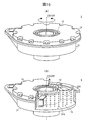
- FIG. 2 is a component development view of the rotary damper 1 according to the first embodiment of the present invention.
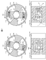
- 3A to 3C are a top view, a front view, and a bottom view of the case 11, and FIG. 3D is a cross-sectional view taken along the line AA of the case 11 shown in FIG. 3A.
- It is. 4A to 4C are a top view, a front view, and a bottom view of the lid 14, respectively.
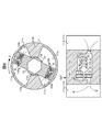
- FIGS. 5A to 5D are a top view, a front view, a side view, and a bottom view of the rotor 12.
- FIG. 6A is a cross-sectional view taken along the line BB of the rotor 12 shown in FIG. 5B, and FIG. 6B is an enlarged view of a portion C in FIG. 6A.
- FIG. 7A and FIG. 7B are diagrams for explaining the operating principle of the rotary damper 1.
- FIG. 8 is a diagram for explaining the operating principle of the rotary damper 1.
- FIG. 9A and FIG. 9B are an external view and a partial cross-sectional view showing a schematic configuration of the rotary damper 2 according to the second embodiment of the present invention.
- FIG. 10B is a component development view of the rotary damper 2.
- FIG. 11A to 11C are a top view, a front view, and a bottom view of the case 21, and FIG. 11D is a DD cross-sectional view of the case 21 shown in FIG. 11A.
- It is. 12 (A) to 12 (C) are a top view, a front view, and a bottom view of the backflow prevention mechanisms 22a and 22b with a pressure regulating function, and FIG. 12 (D) is shown in FIG. 12 (C).
- FIG. 13A and FIG. 13B are diagrams for explaining the operating principle of the rotary damper 2.
- FIG. 14 is a diagram for explaining the operating principle of the rotary damper 2.
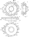
- FIGS. 15A and 15B are an external view and a partial cross-sectional view showing a schematic configuration of the rotary damper 3 according to the third embodiment of the present invention.
- FIG. 16 is a component development view of the rotary damper 3.
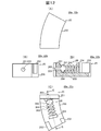
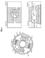
- 17A to 17C are a top view, a front view, and a bottom view of the case 31, and
- FIG. 17D is a cross-sectional view of the case 31 taken along line FF in FIG. 17A.
- 18A is a GG cross-sectional view of the case 31 shown in FIG. 17B
- FIG. 18B is an enlarged view of a portion H in FIG. 18A.
- 19A to 19D are a top view, a front view, a side view, and a bottom view of the rotor 32, respectively.
- 20A is a cross-sectional view taken along the line II of the rotor 32 shown in FIG. 19B
- FIG. 20B is an enlarged view of a portion J in FIG. 20A.
- FIG. 21 is a diagram for explaining the operating principle of the rotary damper 3.
- FIG. 22 is a view for explaining the operating principle of the rotary damper 3.
- FIG. 23 is a diagram for explaining the operating principle of the rotary damper 3.
- FIG. 24A and FIG. 24B are diagrams for explaining the operating principle when a function as a check valve is added to the lip seal 327.
- FIG. 1A and FIG. 1B are an external view and a partial cross-sectional view showing a schematic configuration of a rotary damper 1 according to the first embodiment of the present invention, and FIG. 2 shows components of the rotary damper 1.
- FIG. 1A and FIG. 1B are an external view and a partial cross-sectional view showing a schematic configuration of a rotary damper 1 according to the first embodiment of the present invention, and FIG. 2 shows components of the rotary damper 1.
- FIG. 1A and FIG. 1B are an external view and a partial cross-sectional view showing a schematic configuration of a rotary damper 1 according to the first embodiment of the present invention, and FIG. 2 shows components of the rotary damper 1.
- FIG. 1A and FIG. 1B are an external view and a partial cross-sectional view showing a schematic configuration of a rotary damper 1 according to the first embodiment of the present invention, and FIG. 2 shows components of the rotary damper 1.
- FIG. 1A and FIG. 1B are an external view and
- the rotary damper 1 As shown in the figure, the rotary damper 1 according to the present embodiment is filled in a case 11, a rotor (rotary body) 12 housed in the case 11 so as to be rotatable relative to the case 11, and the case 11.
- a viscous fluid (oil, silicone, etc.) 13 a lid 14 for sealing the rotor 12 together with the viscous fluid 13 in the case 11, and a plurality of screws 18 for fixing the lid 14 to the case 11.
- the rotary damper 1 further includes a check valve 15 and a pressure regulating valve 16.
- FIG. 3A to 3C are a top view, a front view, and a bottom view of the case 11, and FIG. 3D is a cross-sectional view taken along line AA of the case 11 shown in FIG. 3A. .
- the case 11 includes a case main body 112 and a flange portion 118 formed on the outer periphery of the edge portion of the case main body 112.
- a cylindrical chamber (bottomed cylindrical space) 111 is formed in the case body 112.
- the rotor 12 includes a cylindrical rotor main body 131 and vanes 124a and 124b formed on the outer peripheral surface 122 of the rotor main body 131, and rotates around the center line 110 of the cylindrical chamber 111 (the center of the cylindrical chamber 111).
- the cylindrical chamber 111 accommodates the wire 110 so that the wire 110 becomes the rotating shaft 120 of the rotor 12.
- On the inner peripheral surface 113 of the case main body 112 (the side wall surface 113 of the cylindrical chamber 111), an annular space between the outer peripheral surface 122 of the rotor main body 131 and the side wall surface 113 of the cylindrical chamber 111 is radially partitioned.
- a pair of convex partitions 115 a and 115 b protruding toward the outer peripheral surface 122 of the rotor body 131 are provided in the cylindrical chamber 111. Is formed along the center line 110 of the.
- the viscous fluid 13 is filled in regions (111a to 111d in FIG. 7) between the outer peripheral surface 122 of the rotor body 131 and the side wall surface 113 of the cylindrical chamber 111, which are partitioned by these partitions 115a and 115b.
- an opening 117 for inserting one end (lower end) 129 a of the rotor body 131 is formed on the bottom surface 116 of the cylindrical chamber 111.
- a plurality of screw holes 118a are formed in the flange portion 118, and the screws 18 inserted into the through holes 143a of the lid 14 placed on the flange portion 118 are fastened to these screw holes 118a.
- 4A to 4C are a top view, a front view, and a bottom view of the lid 14, respectively.
- the lid 14 is formed with an opening 141 for inserting the other end (upper end 129 b) of the rotor body 131 at a position facing the opening 117 of the bottom surface 116 of the cylindrical chamber 111. Yes. Further, through holes 143a for inserting the screws 18 fastened to the screw holes 118a are formed at positions corresponding to the screw holes 118a of the flange portion 118 of the case 11. Note that a sealing material such as an O-ring may be interposed between the lid 14 and the case 11 so that the viscous fluid 13 does not leak from the cylindrical chamber 111 to the outside.
- a sealing material such as an O-ring may be interposed between the lid 14 and the case 11 so that the viscous fluid 13 does not leak from the cylindrical chamber 111 to the outside.
- FIGS. 5A to 5D are a top view, a front view, a side view, and a bottom view of the rotor 12.
- a through hole 121 for inserting a shaft (not shown) for transmitting a rotational force from the outside to the rotor 12 is formed in the rotor body 131 around the rotating shaft 120.
- the lower end portion 129a of the rotor body 131 (through hole 121) is slidably inserted into the opening 117 formed in the bottom surface 116 of the cylindrical chamber 111 of the case 11, and the upper end of the rotor body 131 (through hole 121).
- the part 129 b is slidably inserted into the opening 141 of the lid 14.
- a sealing material such as an O-ring is interposed between the end portions 129a and 129b of the rotor body 131 and the openings 117 and 141 so that the viscous fluid 13 does not leak outside from the cylindrical chamber 111. You may make it raise.
- a front end surface (a surface facing the side wall surface 113 of the cylindrical chamber 111) 123 protrudes toward the side wall surface 113 of the cylindrical chamber 111 so as to be close to the side wall surface 113 of the cylindrical chamber 111.
- a pair of vanes (rotary blades) 124 a and 124 b are formed along the side wall surface 113 of the cylindrical chamber 111.
- the vanes 124 a and 124 b include a vane 124 a and 124 b between the front end surface 123 and the side wall surface 113 of the cylindrical chamber 111, a lower surface of the vanes 124 a and 124 b (a surface facing the bottom surface 116 of the cylindrical chamber 111) 125, and the cylindrical chamber 111.
- FIG. 6A is a cross-sectional view taken along the line BB of the rotor 12 shown in FIG. 5B, and FIG. 6B is an enlarged view of a portion C in FIG. 5A.
- one vane 124a has a region 111a in the cylindrical chamber 111 (see FIG. 7) partitioned by the vane 124a and the partition 115a of the cylindrical chamber 111, and a partition 115b of the vane 124a and the cylindrical chamber 111.
- a flow path (orifice) 128a for connecting a region 111b (see FIG. 7) in the cylindrical chamber 111 to be partitioned is formed so as to penetrate one side surface 132a and the other side surface 133a of the vane 124a.
- the other vane 124b includes a region 111c (see FIG.
- a flow path 128b for connecting the region 111d (see FIG. 7) in the chamber 111 is formed so as to penetrate the one side surface 132b and the other side surface 133b of the vane 124b.
- a check valve 15 and a pressure regulating valve 16 are paired in each of the flow paths 128a and 128b.
- the check valve 15 is slidably accommodated in the flow direction of the viscous fluid 13 in the second flow path section 1281, and the pressure regulating valve 16 is accommodated in the third flow path section 1282.
- the second flow path section 1281 is filled with the viscous fluid 13 that is filled. It forms so that it may adjoin to the area
- the check valve 15 is a plate-like member arranged in the second flow path section 1281 so as to open and close the second flow path section 1281, and the second flow direction in the direction corresponding to the rotation direction of the rotor 12. Slide in the road section 1281.
- the check valve 15 has a through hole 151 through which the viscous fluid 13 passes. The through hole 151 is opened and closed by the pressure regulating valve 16.
- the pressure regulating valve 16 includes a needle 160 that adjusts the flow rate of the viscous fluid 13 that passes through the through hole 151 of the check valve 15, and an elastic body 162 such as a spring that biases the needle 160 toward the second flow path section 1281.
- the needle 160 has a tapered plug 161 for closing the through hole 151 of the check valve 15 and a rod-shaped stopper 163 provided at the tip of the plug 161 on the check valve 15 side.
- the needle 160 is inserted into the through hole 151 of the check valve 15 from the third flow path section 1282 side so that the stopper 163 protrudes to the second flow path section 1281 side.
- the plug 161 When the check valve 15 moves to the third flow path section 1282 side, the plug 161 is inserted into the through hole 151 of the check valve 15. As a result, the through hole 151 of the check valve 15 is closed by the plug 161. Further, when the needle 160 moves to the first and second flow path sections 1280 and 1281 due to the urging of the elastic body 162, the stopper 163 is connected to the flow paths 128 a and 128 b via the through holes 151 of the check valve 15. It abuts against the inner wall 1283. Thereby, the movement of the plug part 161 to the 1st, 2nd flow-path area 1280,1281 side is controlled.
- such flow paths 128a and 128b are a part of the flow paths 128a and 128b (one flow path port 1284 and first and second flow path sections 1280 and 1281).
- a through hole 1288 is formed in the vanes 124a and 124b in advance, and the check valve 15 and the pressure regulating valve 16 are sequentially inserted into the through holes 1288, and then a part of the flow paths 128a and 128b (the other one) It can be formed by inserting a block 1289 in which a flow path port 1285 and a third flow path section 1282) are formed.
- a guide for preventing the stopper 163 from rattling in the radial direction of the through hole 151 of the check valve 15 (for example, the end surface on the first flow path section 1280 side of the through hole 151).
- Three or more protrusions formed on the portion may be provided.
- FIGS. 7A, 7 ⁇ / b> B, and 8 are diagrams for explaining the operation principle of the rotary damper 1.
- the movement of the viscous fluid 13 between the regions 111a to 111d partitioned by the partitions 115a and 115b and the vanes 124a and 124b of the rotor 12 is caused by the leading end surface 114 of the partitions 115a and 115b and the rotor 12. It is limited only through a gap formed between the outer peripheral surface 122 and the like. As a result, the pressure of the viscous fluid 13 in the regions 111a and 111d increases, and a strong braking torque is generated.
- the needle 160 is moved by the pressure of the viscous fluid 13 that attempts to flow through the flow paths 128a and 128b as shown in FIG.
- the plug portion 161 of the needle 160 is separated from the through hole 151 of the check valve 15, and the flow paths 128 a and 128 b are opened.
- the rotational force applied in the forward direction applied to the rotor 12 or the case 11 is limited.
- the rotary damper 1 that generates a strong braking torque is provided with a pressure regulating valve 16 that releases the restriction on the movement of the viscous fluid 13 from the high pressure side to the low pressure side when the rotational force is equal to or greater than a predetermined value. Therefore, according to the present embodiment, even when a rotational force greater than expected is applied to the rotor 12 or the case 11, the pressure on the viscous fluid 13 filled in the cylindrical chamber 111 can be suppressed to a predetermined value or less. The possibility that the rotary damper 1 is damaged can be reduced.
- one vane 124a of the rotor 12 is provided with a partition 115a, 115b of the cylindrical chamber 111 and a flow path 128a that connects the regions 111a, 111b separated by the vane 124a.
- the other vane 124b of the rotor 12 is provided with a flow path 128b that connects the partitions 115a and 115b of the cylindrical chamber 111 and the regions 111c and 111d separated by the vane 124b.
- the check valve 15 and the pressure regulating valve 16 are configured as described above, so that the check valve 15 and the pressure regulating valve 16 are paired in each of the flow paths 128a and 128b. As described above, according to the present embodiment, the check valve 15 and the pressure regulating valve 16 are not disposed in separate flow paths, but are disposed in the same flow paths 128a and 128b. Is possible.
- the flow paths 128a and 128b are formed in the vanes 124a and 124b of the rotor 12, and the check valve 15 and the pressure regulating valve 16 are internally provided in the flow paths 128a and 128b.
- the present invention is not limited to this.
- the flow paths 128a and 128b may be formed in the partitions 115a and 115b of the cylindrical chamber 111 of the case 11, and the check valve 15 and the pressure regulating valve 16 may be provided in the flow paths 128a and 128b as a pair.
- FIG. 9A and FIG. 9B are an external view and a partial cross-sectional view showing a schematic configuration of the rotary damper 2 according to the second embodiment of the present invention
- FIG. 10 is a development of parts of the rotary damper 2.
- the rotary damper 2 is filled in a case 21, a rotor (rotating body) 12 a housed in the case 21 so as to be rotatable relative to the case 21, and the case 21.
- the viscous fluid 13, the screw 18 and the lid 14 are the same as those used in the rotary damper 1 according to the first embodiment.
- the configuration of the rotor 12a is the same as that of the rotor 12 used in the rotary damper 1 according to the first embodiment except that the flow paths 128a and 128b are not formed in the vanes 124a and 124b. Therefore, in the following, description of these will be omitted.
- FIG. 11A to 11C are a top view, a front view, and a bottom view of the case 21, and FIG. 11D is a DD cross-sectional view of the case 21 shown in FIG. 11A. .
- the case 21 includes a case main body 212 and a flange portion 218 formed on the outer periphery of the edge portion of the case main body 212.
- the case main body 212 is formed with a cylindrical chamber (cylindrical space with a bottom) 211.
- the rotor 12a includes a cylindrical rotor main body 131 and vanes 124a and 124b formed on the outer peripheral surface 122 of the rotor main body 131, and rotates around the center line 210 of the cylindrical chamber 211 (the center of the cylindrical chamber 211).
- the cylindrical chamber 211 accommodates the wire 210 so that the wire 210 becomes the rotating shaft 220 of the rotor 12a.
- An opening 217 for inserting one end (lower end) 129a of the rotor 12a is formed on the bottom surface 216 of the cylindrical chamber 211.
- an annular space between the outer peripheral surface 122 of the rotor main body 131 and the side wall surface 213 of the cylindrical chamber 211 is radially partitioned.
- a pair of convex partitions 215 a and 215 b (a pair of convex partitions 215 a and 215 b in which the front end surface 114 is close to the outer peripheral surface 122 of the rotor 12) protruding toward the outer peripheral surface 122 of the rotor body 131 are the cylindrical chamber 211.
- the viscous fluid 13 is filled in a region (211a to 211d in FIG. 13) between the outer peripheral surface 122 of the rotor body 131 and the side wall surface 213 of the cylindrical chamber 211, which is partitioned by these partitions 215a and 215b.
- One partition 215a includes a region 211a (see FIG. 13) in the cylindrical chamber 211 formed by the partition 215a and the vane 124a of the rotor 12a, and a cylindrical chamber 211 formed by the partition 215a and the vane 124b of the rotor 12a.
- a groove-like flow path 228a connecting the region 211c (see FIG. 13) is formed, and the backflow prevention mechanism 22a with a pressure adjusting function is slidably accommodated in the flow path 228a.
- the other partition 215b includes a region 211d (see FIG.
- a flow path 228b that connects the region 211b (see FIG. 13) in 211 is formed, and the backflow prevention mechanism 22b with a pressure adjusting function is slidably accommodated in the flow path 228b.
- Each of the flow paths 228a and 228b is formed with a convex portion 219 for restricting the slide range of the backflow prevention mechanisms 22a and 22b with a pressure adjusting function by narrowing a part of the radial flow path width. .
- a plurality of screw holes 218a are formed in the flange portion 218, and the screws 18 inserted into the through holes 143a of the lid 14 placed on the flange portion 118 are fastened to these screw holes 218a.
- FIG. 12A to 12C are a top view, a front view, and a bottom view of the backflow prevention mechanisms 22a and 22b with a pressure regulating function
- FIG. 12D is a pressure regulation shown in FIG. 12C.
- It is EE sectional drawing of backflow prevention mechanism 22a, 22b with a function.
- the backflow prevention mechanisms 22a and 22b with a pressure regulation function include a check valve 25 and a pressure regulation valve 26.
- the check valve 25 fills when sliding in the circumferential direction and rotating one of the flow passages 228a and 228b (rotor 12a in the normal rotation direction ( ⁇ direction in the present embodiment, see FIG. 13)).
- a stopper 252 that restricts the sliding range of the valve part 251, a holding part 254 that holds the pressure regulating valve 26, and a connecting part 255 that connects the valve part 251, the stopper 252, and the holding part 254 are provided.
- the valve portion 251 is formed with a through hole 253 that is opened and closed by the pressure regulating valve 26.
- the holding portion 254 and the stopper 252 are filled with the viscous fluid 13 when the rotor 12a is rotated in the normal rotation direction ( ⁇ direction in the present embodiment, see FIG. 13) with respect to the valve portion 251. Is formed so as to be located on the side of the regions 211b and 211c (see FIG. 13) where pressure is reduced.
- the connecting portion 255 is a valve portion when the rotor 12a rotates in the reverse rotation direction ( ⁇ direction in the present embodiment, see FIG. 14) and the stopper 252 contacts the convex portion 219 in the partitions 215a and 215b.
- 251 has such a length that it is separated from the channel openings 229a and 229b of the channels 228a and 228b by a predetermined distance.
- the pressure regulating valve 26 includes a needle 264 that adjusts the flow rate of the viscous fluid 13 that passes through the through hole 253 of the valve portion 251 of the check valve 25, one end fixed to the holding portion 254 of the check valve 25, and a needle at the other end. And an elastic body 262 such as a spring for urging the H.264 toward the regions 211b and 211c.
- the needle 264 includes a tapered plug portion 261 for closing the through hole 253 of the valve portion 251 of the check valve 25 and a rod-shaped guide 263 provided at the distal end portion of the plug portion 261 on the valve portion 251 side. .
- the guide 263 is inserted into the through hole 253 of the valve portion 251 from the region 211b, 211c side, and guides the plug portion 261 into the through hole 253 of the valve portion 251 of the check valve 25.
- the needle 264 moves to the valve portion 251 side of the check valve 25 by the urging of the elastic body 262
- the plug portion 261 is guided by the guide 263 and inserted into the through hole 253 of the valve portion 251.
- the through hole 253 of the valve portion 251 of the check valve 25 is closed by the plug portion 261.
- a guide for preventing the guide 263 from rattling in the radial direction of the through hole 253 of the valve portion 251 (for example, three or more points formed on the outer end surface portion of the through hole 253) May be provided.
- FIG. 13A, FIG. 13B, and FIG. 14 are diagrams for explaining the operation principle of the rotary damper 2.
- the movement of the viscous fluid 13 between the regions 211a to 211d delimited by the partitions 215a and 215b and the vanes 124a and 124b of the rotor 12a is caused by the leading end surface 214 of the partitions 215a and 215b and the rotor body 131. It is limited only through a gap formed between the outer peripheral surface 122 and the outer peripheral surface 122. As a result, the pressure of the viscous fluid 13 in the areas 211a and 211d increases, and a strong braking torque is generated.
- the needle 264 is pushed back by the pressure of the viscous fluid 13 that attempts to flow through the flow paths 228a and 228b, as shown in FIG.
- the plug portion 261 of the needle 264 is separated from the through hole 253 of the valve portion 251, and the flow paths 228a and 228b are opened.
- the restriction on the movement of the viscous fluid 13 between the regions 211a to 211d delimited by the partitions 215a and 215b and the vanes 124a and 124b of the rotor 12a is released, and the viscous fluid 13 is allowed to flow into the flow path 228a.
- 228b and the through hole 253 of the valve portion 251 move from the region 211a, 211d to the region 211c, 211b.
- the viscous fluid 13 moves from the areas 211b and 211c to the areas 211a and 211d via the flow paths 228a and 228b.
- a weak braking torque is generated without increasing the pressure of the viscous fluid 13 in the regions 211b and 211c.
- the pressure on the viscous fluid 13 filled in the cylindrical chamber 211 is reduced to a predetermined value or less. Since it can suppress, possibility that the rotary damper 2 will be damaged can be made low.
- the pressure regulating valve 26 is incorporated in the check valve 25 to form the backflow preventing mechanisms 22a and 22b with a pressure regulating function, the check valve 25 and the pressure regulating valve 26 can be disposed in the same flow path 228a and 228b.
- the rotary damper 2 can be reduced in size.
- the flow paths 228a and 228b are formed in the partitions 215a and 215b of the cylindrical chamber 211, and the backflow prevention mechanisms 22a and 22b with a pressure adjusting function are provided in the flow paths 228a and 228b.
- the present invention is not limited to this.
- the flow paths 228a and 228b may be formed in the vanes 124a and 124b of the rotor 12a, and the backflow prevention mechanisms 22a and 22b with a pressure adjusting function may be provided in the flow paths 228a and 228b.
- ⁇ Third embodiment> 15A and 15B are an external view and a partial cross-sectional view showing a schematic configuration of the rotary damper 3 according to the third embodiment of the present invention, and FIG. FIG.
- the rotary damper 3 includes a case 31, a rotor (rotary body) 32 housed in the case 31 so as to be rotatable relative to the case 31, and a case 31.
- the filled viscous fluid 13, the lid 14 for sealing the rotor 32 together with the viscous fluid 13 in the case 31, and a plurality of screws 18 for fixing the lid 14 to the case 11 are provided.
- the rotary damper 3 further includes a check valve 35 and a pressure regulating valve 36.
- the viscous fluid 13, the screw 18 and the lid 14 are the same as those used in the rotary damper 1 according to the first embodiment. Therefore, in the following, description of these will be omitted.
- FIG. 17A to 17C are a top view, a front view, and a bottom view of the case 31, and FIG. 17D is a cross-sectional view taken along the line FF of the case 31 shown in FIG. 17A. .
- the case 31 includes a case main body 312 and a flange portion 318 formed on the outer periphery of the edge of the case main body 312.
- the case body 312 has a cylindrical chamber (cylindrical space with a bottom) 311 formed therein.
- the rotor 32 includes a cylindrical rotor main body 331 and vanes 324a and 324b formed on the outer peripheral surface 322 of the rotor main body 331, and rotates around the center line 310 of the cylindrical chamber 311 (the center of the cylindrical chamber 311).
- the cylindrical chamber 311 is accommodated so that the wire 310 becomes the rotating shaft 320 of the rotor 32.
- a pair of convex partitions 315 a and 315 b (a pair of convex partitions 315 a and 315 b in which the tip surface 314 is close to the side surface 322 of the rotor 32) projecting toward the outer peripheral surface 322 of the rotor body 331 is the cylindrical chamber 311. It is formed along the center line 310.
- the viscous fluid 13 is filled in a region (311a to 311d in FIG. 22) between the outer peripheral surface 322 of the rotor main body 331 and the side wall surface 313 of the cylindrical chamber 311 partitioned by the partitions 315a and 315b.
- an opening 317 for inserting one end (lower end) 329a of the rotor body 331 is formed on the bottom surface 316 of the cylindrical chamber 311.
- One partition 315a includes a region 311a (see FIG. 22) in a cylindrical chamber 311 formed by the partition 315a and the vane 324a of the rotor 32, and a cylinder formed by the partition 315a and the vane 324b of the rotor 32.
- a check valve flow path (orifice) 338a that connects the region 311c (see FIG. 22) in the chamber 311 is formed.
- the other partition 315b is formed by a region 311b (see FIG. 22) in the cylindrical chamber 311 formed by the partition 315b and the vane 324a of the rotor 32, and the partition 315b and the vane 324b of the rotor 32.
- a check valve flow path (orifice) 338b that connects the region 311d (see FIG. 22) in the cylindrical chamber 311 is formed.
- FIG. 18A is a cross-sectional view taken along the line GG of the case 31 shown in FIG. 17B, and FIG. 18B is an enlarged view of a portion H in FIG. 18A.
- a spherical check valve 35 is provided in each of the check valve flow paths 338a and 338b.
- the check valve flow paths 338a and 338b include a first check valve flow path section 3381 and a second reverse valve having a larger radial flow path cross-sectional area than the first check valve flow path section 3381.
- a stop valve channel section 3382 is formed.
- the second check valve flow passage section 3382 has a diameter larger than the diameter of the check valve 35, and the check valve 35 that opens and closes the first check valve flow path section 3381 is slidable. Is housed in.
- a stopper 3383 for restricting the slide range of the check valve 35 is formed in the second check valve flow path section 3382.
- the first check valve channel section 3381 rotates the rotor 32 in the forward rotation direction ( ⁇ direction in the present embodiment, see FIG. 22) with respect to the second check valve channel section 3382. In this case, the filled viscous fluid 13 is formed adjacent to the regions 311b and 311c to be decompressed.
- 19A to 19D are a top view, a front view, a side view, and a bottom view of the rotor 32, respectively.
- a through hole 321 for inserting a shaft (not shown) for transmitting a rotational force from the outside to the rotor 32 is formed in the rotor body 331 with the rotary shaft 320 as a center.
- the lower end 329a of the rotor body 331 (through hole 321) is slidably inserted into an opening 317 formed in the bottom surface 316 of the cylindrical chamber 311 of the case 31, and the upper end of the rotor body 331 (through hole 321).
- the part 329b is slidably inserted into the opening 141 of the lid 14.
- a sealing material such as an O-ring is interposed between the end portions 329a and 329b of the rotor main body 331 and the openings 317 and 141 so that the viscous fluid 13 does not leak outside from the cylindrical chamber 311. You may make it raise.
- the outer peripheral surface 322 of the rotor body 331 faces the side wall surface 313 of the cylindrical chamber 311 so that the front end surface (surface facing the side wall surface 313 of the cylindrical chamber 311) 323 is close to the side wall surface 313 of the cylindrical chamber 311.
- a pair of vanes (rotating blades) 324 a and 324 b protruding in this manner are formed along the rotating shaft 320 of the rotor 32.
- the vanes 324 a and 324 b include a vane 324 a and 324 b between the front end surface 323 and the side wall surface 313 of the cylindrical chamber 311, a lower surface of the vanes 324 a and 324 b (a surface facing the bottom surface 316 of the cylindrical chamber 311) 325 and the cylindrical chamber 311.
- a lip seal 327 (see FIG. 15) for closing a gap formed between the bottom surface 316 of the blades 316 and the upper surfaces (surfaces on the lid 14 side) 326 of the vanes 324a and 324b and the lower surface 142 of the lid 14. It is attached.
- FIG. 20A is a cross-sectional view taken along the line II of the rotor 32 shown in FIG. 19B, and FIG. 20B is an enlarged view of a portion J in FIG. 20A.
- () Is a figure for demonstrating the manufacturing method of the flow paths 328a and 328b.
- One vane 324a includes an area 311a (see FIG. 22) in the cylindrical chamber 311 formed by the vane 324a and the partition 315a of the cylindrical chamber 311 and a cylindrical chamber 311 formed by the partition 315b of the vane 324a and the cylindrical chamber 311.
- a pressure regulating valve channel (orifice) 328a that connects the inner region 311b (see FIG. 22) is formed.
- the other vane 324b is formed by a region 311c (see FIG. 22) in the cylindrical chamber 311 formed by the vane 324b and the partition 315a of the cylindrical chamber 311 and a partition 315b of the vane 324b and the cylindrical chamber 311.
- a pressure regulating valve channel 328b that connects the region 311d (see FIG. 22) in the cylindrical chamber 311 is formed.
- Each of the pressure regulating valve channels 328a and 328b has a channel port 3280 formed on one side surface 332a and 332b of the vanes 324a and 324b and a channel port formed on the other side surface 333a and 333b of the vanes 324a and 324b.
- a pressure regulating valve channel section 3282 having a larger radial channel cross-sectional area than 3281 is formed between the channel ports 3280 and 3281 so that the axis is shifted from the axis of the channel ports 3280 and 3281.
- the pressure regulating valve 36 is accommodated in the pressure regulating valve channel section 3282.
- the pressure regulating valve 36 includes a needle 360 that adjusts the flow rate of the viscous fluid 13 that passes through one flow path port 3280 of the pressure regulating valve flow paths 328a and 328b, and the needle 360 that is one flow path port of the pressure regulating valve flow paths 328a and 328b.
- an elastic body 362 such as a spring that presses toward the 3280 side.
- one flow path port 3280 of the pressure regulating valve flow paths 328a and 328b is applied with the filled viscous fluid 13 when the rotor 32 is rotated in the forward rotation direction ( ⁇ direction in the present embodiment). It is a channel opening facing the areas 311a and 311b (see FIG. 22) to be pressed.
- the needle 360 has a tapered plug portion 361 for closing one flow path port 3280 of the pressure regulating valve flow paths 328a and 328b, and a guide 363 provided at the tip of the plug section 361.
- the guide 363 is inserted into one flow path port 3280 of the pressure regulating valve flow paths 328a and 328b from the region 311b and 311c side, and the plug portion 361 is guided to one flow path port 3280 of the pressure regulating valve flow paths 328a and 328b. To do.
- the plug portion 361 When the needle 360 moves to the one flow passage port 3280 side of the pressure regulating valve flow paths 328a and 328b by the urging of the elastic body 362, the plug portion 361 is guided to the guide 363, and the pressure regulating valve flow paths 328a and 328b are moved. It is inserted into one flow path port 3280. As a result, one flow path port 3280 of the pressure regulating valve flow paths 328 a and 328 b is closed by the plug portion 361.
- the pressure regulating valve channels 328a and 328b penetrate through part of the pressure regulating valve channels 328a and 328b (one channel port 3280 and the pressure regulating valve channel section 3282).
- a hole 3284 is formed in the vanes 324a and 324b in advance, and the pressure regulating valve 36 is inserted into the through hole 3284, and then a part of the pressure regulating valve channels 328a and 328b (the other channel port 3281) is formed. It can be formed by inserting the block 3285.
- a guide for preventing the guide 363 from rattling with respect to the radial direction of the flow path port 3280 (for example, formed on the end surface of the flow path port 3280 on the pressure regulating valve flow path section 3282 side).
- Three or more protrusions may be provided.
- 21 to 23 are diagrams for explaining the operation principle of the rotary damper 3.
- the check valve 35 is the first check valve.
- the second check valve channel section 3382 is slid to the boundary between the first check valve channel section 3382 and the second check valve channel section 3382, and the first check valve channel section 3381 is Block it. As a result, the check valve channels 338a and 338b are closed.
- the movement of the viscous fluid 13 between the regions 311a to 311d partitioned by the partitions 315a and 315b and the vanes 324a and 324b of the rotor 32 is caused by the leading end surface 314 of the partitions 315a and 315b and the rotor body 331. It is limited only through a gap or the like formed between the outer peripheral surface 322 and the outer peripheral surface 322. As a result, the pressure of the viscous fluid 13 in the regions 311a and 311d increases, and a strong braking torque is generated.
- the needle 360 is pushed back by the pressure of the viscous fluid 13 that is about to flow through the pressure regulating valve channels 328a and 328b, as shown in FIG.
- the plug portion 361 of the needle 360 is separated from the first pressure regulating valve channel section 3281, and the pressure regulating valve channels 328a and 328b are opened. Therefore, the restriction on the movement of the viscous fluid 13 via the pressure regulating valve flow paths 328a and 328b is released, and the viscous fluid 13 is transferred from the areas 311a and 311d to the areas 311b and the pressure regulating valve flow paths 328a and 328b. Move to 311c. Thereby, it is possible to prevent the pressure of the viscous fluid 13 in the regions 311a and 311d from becoming higher than a predetermined value while generating a strong braking torque.
- the pressure on the viscous fluid 13 filled in the cylindrical chamber 311 is reduced to a predetermined value or less. Since it can suppress, possibility that the rotary damper 3 will be damaged can be made low.
- the flow paths 328a and 328b provided with the pressure regulating valve 36 are formed in the vanes 324a and 324b of the rotor 32, and the flow paths 338a and 338b provided with the check valve 35 are formed in the partitions 315a and 315b of the cylindrical chamber 311. Therefore, the rotary damper 3 can be downsized as compared with the case where these flow paths are collectively formed in one of the vanes 324a and 324b and the partitions 315a and 315b.
- flow paths 328a and 328b for the check valve 35 are formed in the partitions 315a and 315b of the cylindrical chamber 311 and flow paths 328a and 328b for the pressure regulating valve 36 are formed in the vanes 324a and 324b of the rotor 32.
- a flow path for the pressure regulating valve 36 may be formed in the partitions 315 a and 315 b of the cylindrical chamber 311, and a flow path for the check valve 35 may be formed in the vanes 324 a and 324 b of the rotor 32.
- these flow paths may be formed in one of the vanes 324a and 324b and the partitions 315a and 315b.
- the check valve 35 and the check valve flow paths 338a and 338b are provided by adding a function as a check valve to the lip seal 327 attached to the vanes 324a and 324b of the rotor 32. It may be omitted. That is, when the rotor 32 rotates relative to the case 31 in the normal rotation direction ( ⁇ direction in the present embodiment), the tip surfaces 323 of the vanes 324a and 324b and the cylinder as shown in FIG. The pressure of the viscous fluid 13 flowing through the gap 38 with the side wall surface 313 of the chamber 311 is deformed in a direction to close the gap 38, and the rotor 32 is relative to the case 31 in the reverse rotation direction ( ⁇ direction in the present embodiment). 24B, as shown in FIG.
- the tip portion 3271 of the lip seal 327 is deformed in a direction to open the gap 38 by the pressure of the viscous fluid 13 flowing through the gap 38. Gives elasticity.
- the rotary damper 3 can be manufactured at a lower cost by omitting the check valve 35 and the check valve flow paths 338a and 338b.
- a pair of partitions 115a, 115b, 215a, 215b, 315a, 315b are provided in the cylindrical chambers 111, 211, 311 and the rotors 12, 12a, 32 are provided.
- the case where the pair of vanes 124a, 124b, 324a, and 324b is provided has been described as an example. However, the present invention is not limited to this. If the number of partitions formed in the cylindrical chamber and the number of vanes formed in the rotor are the same, one or three or more may be formed.
- rotary dampers 1 to 3 can be widely applied to seat seats with a reclining function used in, for example, automobiles, railway vehicles, airplanes, ships, and the like.
- the present invention for example, in a seat with a reclining function used in an automobile, a railway vehicle, an aircraft, a ship, etc., is used for suppressing the pressure with respect to the viscous fluid filled in the cylindrical chamber of the rotary damper to a predetermined value or less. Applicable.
Abstract
Description
前記回転力が所定値以上の場合に開放して、前記粘性流体の移動の制限を解除する調圧弁を有する。 For example, the present invention is a rotary damper that generates a braking torque with respect to an applied rotational force by limiting movement of a filled viscous fluid,
A pressure regulating valve that is opened when the rotational force is equal to or greater than a predetermined value and releases the restriction on the movement of the viscous fluid.
前記粘性流体が充填された円筒室を備えるケースと、
前記ケースに対して、前記円筒室の中心線周りに相対的に回転するように前記円筒室に収容されたロータと、
前記ロータの回転方向により開閉する逆止弁と、をさらに有し、
前記円筒室の側壁面には、
先端面が前記ロータの外周面と近接するように、当該円筒室の中心線に沿って凸状の仕切りが形成されており、
前記ロータの外周面には、
先端面が前記円筒室の側壁面と近接するベーンが形成されており、
前記逆止弁は、
前記ケースに対する前記ロータの正転方向への相対的な回転に対し閉成して、前記仕切りおよび前記ベーンにより区切られる領域間における前記粘性流体の移動を制限する一方、前記ケースに対する前記ロータの逆転方向への相対的な回転に対し開放して、前記仕切りおよび前記ベーンにより区切られる領域間における前記粘性流体の移動を許容し、
前記調圧弁は、
前記ケースに対して前記ロータを前記正転方向に相対的に回転させるように加えられた前記回転力が前記所定値以上の場合に開放して、前記仕切りおよび前記ベーンにより区切られる領域間における前記粘性流体の移動の制限を解除するものでもよい。 Here, the rotary damper
A case comprising a cylindrical chamber filled with the viscous fluid;
A rotor accommodated in the cylindrical chamber so as to rotate relative to the case around a center line of the cylindrical chamber;
A check valve that opens and closes depending on the rotation direction of the rotor,
On the side wall surface of the cylindrical chamber,
A convex partition is formed along the center line of the cylindrical chamber so that the front end surface is close to the outer peripheral surface of the rotor,
On the outer peripheral surface of the rotor,
A vane whose tip surface is close to the side wall surface of the cylindrical chamber is formed,
The check valve is
Closed against relative rotation of the rotor in the forward rotation direction with respect to the case, restricts the movement of the viscous fluid between regions partitioned by the partition and the vane, while reversing the rotor with respect to the case Allowing movement of the viscous fluid between regions partitioned by the partition and the vane, open to relative rotation in a direction;
The pressure regulating valve is
When the rotational force applied to rotate the rotor relative to the case relative to the forward rotation direction is greater than or equal to the predetermined value, the rotor is opened and the region between the partitions and the regions partitioned by the vanes is opened. The restriction on the movement of the viscous fluid may be canceled.
図1(A)および図1(B)は、本発明の第一実施の形態に係るロータリダンパ1の概略構成を示す外観図および部分断面図であり、図2は、このロータリダンパ1の部品展開図である。 <First embodiment>
FIG. 1A and FIG. 1B are an external view and a partial cross-sectional view showing a schematic configuration of a
図9(A)および図9(B)は、本発明の第二実施の形態に係るロータリダンパ2の概略構成を示す外観図および部分断面図であり、図10は、ロータリダンパ2の部品展開図である。 <Second embodiment>
FIG. 9A and FIG. 9B are an external view and a partial cross-sectional view showing a schematic configuration of the
図15(A)および図15(B)は、本発明の第三実施の形態に係るロータリダンパ3の概略構成を示す外観図および部分断面図であり、図16は、ロータリダンパ3の部品展開図である。 <Third embodiment>
15A and 15B are an external view and a partial cross-sectional view showing a schematic configuration of the
Claims (9)
- 充填された粘性流体の移動を制限することにより、加えられた回転力に対して制動トルクを発生させるロータリダンパであって、
前記回転力が所定値以上の場合に開放して、前記粘性流体の移動の制限を解除する調圧弁を有する
ことを特徴とするロータリダンパ A rotary damper that generates a braking torque against an applied rotational force by limiting the movement of the filled viscous fluid,
A rotary damper having a pressure regulating valve that is opened when the rotational force is greater than or equal to a predetermined value and releases the restriction on the movement of the viscous fluid. - 請求項1に記載のロータリダンパであって、
前記粘性流体が充填された円筒室を備えるケースと、
前記ケースに対して、前記円筒室の中心線周りに相対的に回転するように前記円筒室に収容されたロータと、
前記ロータの回転方向により開閉する逆止弁と、をさらに有し、
前記円筒室の側壁面には、
先端面が前記ロータの外周面と近接するように、当該円筒室の中心線に沿って凸状の仕切りが形成されており、
前記ロータの外周面には、
先端面が前記円筒室の側面と近接するベーンが形成されており、
前記逆止弁は、
前記ケースに対する前記ロータの正転方向への相対的な回転に対し閉成して、前記仕切りおよび前記ベーンにより区切られる領域間における前記粘性流体の移動を制限する一方、前記ケースに対する前記ロータの逆転方向への相対的な回転に対し開放して、前記仕切りおよび前記ベーンにより区切られる領域間における前記粘性流体の移動を許容し、
前記調圧弁は、
前記ケースに対して前記ロータを前記正転方向に相対的に回転させるように加えられた前記回転力が前記所定値以上の場合に開放して、前記仕切りおよび前記ベーンにより区切られる領域間における前記粘性流体の移動の制限を解除する
ことを特徴とするロータリダンパ。 The rotary damper according to claim 1,
A case comprising a cylindrical chamber filled with the viscous fluid;
A rotor housed in the cylindrical chamber so as to rotate relative to the case around a center line of the cylindrical chamber;
A check valve that opens and closes depending on the rotation direction of the rotor,
On the side wall surface of the cylindrical chamber,
A convex partition is formed along the center line of the cylindrical chamber so that the front end surface is close to the outer peripheral surface of the rotor,
On the outer peripheral surface of the rotor,
A vane whose tip surface is close to the side surface of the cylindrical chamber is formed,
The check valve is
Closed against relative rotation of the rotor in the forward rotation direction with respect to the case, restricts the movement of the viscous fluid between regions partitioned by the partition and the vane, while reversing the rotor with respect to the case Allowing movement of the viscous fluid between regions partitioned by the partition and the vane, open to relative rotation in a direction;
The pressure regulating valve is
When the rotational force applied to rotate the rotor relative to the case relative to the forward rotation direction is greater than or equal to the predetermined value, the rotor is opened between the regions partitioned by the partition and the vane. A rotary damper characterized by releasing the restriction on the movement of viscous fluid. - 請求項2に記載のロータリダンパであって、
前記仕切りおよび前記ベーンの少なくも一方には、
前記仕切りおよび前記ベーンにより区切られる領域間を繋ぐ流路が形成されており、
前記調圧弁は、
前記ロータを正転方向に相対的に回転させるように加えられた前記回転力が前記所定値以上の場合に前記流路を開口し、当該回転力が前記所定値未満の場合に前記流路を閉口する
ことを特徴とするロータリダンパ。 The rotary damper according to claim 2,
In at least one of the partition and the vane,
A flow path connecting the partitions and the regions partitioned by the vanes is formed,
The pressure regulating valve is
The flow path is opened when the rotational force applied to relatively rotate the rotor in the forward rotation direction is equal to or greater than the predetermined value, and the flow path is opened when the rotational force is less than the predetermined value. A rotary damper characterized by closing. - 請求項3に記載のロータリダンパであって、
前記逆止弁は、
前記ケースに対して前記ロータを前記正転方向に相対的に回転させた場合に前記流路を閉口し、前記ケースに対して前記ロータを前記逆転方向に相対的に回転させた場合に前記流路を開口し、
前記調圧弁は、
前記ケースに対して前記ロータを前記正転方向に相対的に回転させるように加えられた前記回転力が前記所定値以上の場合に、前記逆止弁により閉口した前記流路を開口する
ことを特徴とするロータリダンパ。 The rotary damper according to claim 3,
The check valve is
The flow path is closed when the rotor is rotated relative to the case in the forward rotation direction, and the flow path is closed when the rotor is rotated relative to the case in the reverse rotation direction. Open the road,
The pressure regulating valve is
Opening the flow path closed by the check valve when the rotational force applied to rotate the rotor relative to the case relative to the forward rotation direction is greater than or equal to the predetermined value. A featured rotary damper. - 請求項4に記載のロータリダンパであって、
前記流路には、
前記逆止弁をスライド自在に収容するための第一の流路区間と、前記調圧弁を収容するための第二の流路区間と、が形成されており、
前記第一の流路区間は、
前記第二の流路区間に対して、前記仕切りおよび前記ベーンにより区切られる領域のうち、前記ケースに対して前記ロータを前記正転方向に相対的に回転させた場合に当該領域内の前記粘性流体が加圧される領域側に隣接しており、
前記逆止弁は、
貫通孔が形成された板状部材であり、
前記調圧弁は、
前記逆止弁の貫通孔に対する栓部と、前記栓部を前記第一の流路区間側へ押圧する弾性体と、前記栓部の前記第一の流路区間内への移動を規制するストッパと、を有し、
前記ケースに対して前記ロータを前記正転方向に相対的に回転させた場合に、前記逆止弁が前記第一の流路区間の前記第二の流路区間側端部までスライドし、前記回転力が前記所定値未満ならば、前記弾性体により押圧された前記栓部が当該逆止弁の貫通孔に押し込まれ、前記流路を閉口し、前記回転力が前記所定値以上ならば、前記流路を流れようとする前記粘性流体の圧力により前記栓部が押し戻されて当該逆止弁の貫通孔から離れ、前記流路を開口し、
前記ケースに対して前記ロータを前記逆転方向に相対的に回転させた場合に、前記逆止弁が前記第一の流路区間の前記第二の流路区間側端部から離れる方向にスライドし、前記ストッパにより前記第一の流路区間内への移動が規制された前記栓部が当該逆止弁の貫通孔に押し込まれることなく、前記流路を開口する
ことを特徴とするロータリダンパ。 The rotary damper according to claim 4,
In the channel,
A first flow path section for slidably storing the check valve and a second flow path section for storing the pressure regulating valve are formed,
The first channel section is
Of the region partitioned by the partition and the vane with respect to the second flow path section, the viscosity in the region when the rotor is rotated relative to the case in the normal rotation direction. Adjacent to the area where the fluid is pressurized,
The check valve is
A plate-like member in which a through hole is formed;
The pressure regulating valve is
A plug portion for the through hole of the check valve, an elastic body that presses the plug portion toward the first flow path section, and a stopper that restricts the movement of the plug section into the first flow path section And having
When the rotor is rotated relative to the case in the forward rotation direction, the check valve slides to the second flow path section side end of the first flow path section, If the rotational force is less than the predetermined value, the plug portion pressed by the elastic body is pushed into the through hole of the check valve, closes the flow path, and if the rotational force is equal to or greater than the predetermined value, The plug portion is pushed back by the pressure of the viscous fluid about to flow through the flow path to leave the through hole of the check valve, and the flow path is opened.
When the rotor is rotated relative to the case in the reverse rotation direction, the check valve slides away from the second flow path section side end of the first flow path section. The rotary damper is characterized in that the stopper is restricted from moving into the first passage section by the stopper, and the passage is opened without being pushed into the through hole of the check valve. - 請求項4に記載のロータリダンパであって、
前記流路は、
路幅を狭めるための凸部が形成されており、
前記逆止弁は、
前記凸部により規制される範囲内で前記流路内をスライド自在に収容された、貫通孔を備える板状の弁部と、当該弁部に対して、前記仕切りおよび前記ベーンにより区切られる領域のうち、前記ケースに対して前記ロータを前記正転方向に相対的に回転させた場合に当該領域内の前記粘性流体が減圧される領域側に配された、前記調圧弁を収容するための収容部と、を有し、
前記調圧弁は、
前記弁部の貫通孔に対する栓部と、前記栓部を前記弁部の貫通孔へ押圧する弾性体と、を有し、
前記ケースに対して前記ロータを前記正転方向に相対的に回転させた場合に、前記逆止弁の弁部が前記流路の凸部と当接するまでスライドし、前記回転力が前記所定値未満ならば、前記弾性体により押圧された前記栓部が当該逆止弁の弁部の貫通孔に押し込まれ、前記流路を閉口し、前記回転力が前記所定値以上ならば、前記流路を流れようとする前記粘性流体の圧力により前記栓部が押し戻されて当該逆止弁の弁部の貫通孔から離れ、前記流路を開口し、
前記ケースに対して前記ロータを前記逆転方向に相対的に回転させた場合に、前記逆止弁の弁部が前記流路の凸部から離れる方向へスライドし、前記流路を開口する
ことを特徴とするロータリダンパ。 The rotary damper according to claim 4,
The flow path is
Protrusions for narrowing the road width are formed,
The check valve is
A plate-like valve portion having a through-hole, slidably accommodated in the flow path within a range regulated by the convex portion, and an area partitioned by the partition and the vane with respect to the valve portion Among these, the housing for housing the pressure regulating valve, which is disposed on the region side where the viscous fluid in the region is decompressed when the rotor is rotated relative to the case in the forward rotation direction. And
The pressure regulating valve is
A plug portion with respect to the through hole of the valve portion, and an elastic body that presses the plug portion against the through hole of the valve portion,
When the rotor is rotated relative to the case in the forward rotation direction, the valve portion of the check valve slides until it comes into contact with the convex portion of the flow path, and the rotational force is the predetermined value. If less, the plug portion pressed by the elastic body is pushed into the through hole of the valve portion of the check valve to close the flow path, and if the rotational force is equal to or greater than the predetermined value, the flow path The plug portion is pushed back by the pressure of the viscous fluid trying to flow through, away from the through hole of the valve portion of the check valve, and the flow path is opened
When the rotor is rotated relative to the case in the reverse rotation direction, the valve portion of the check valve slides away from the convex portion of the flow path to open the flow path. A featured rotary damper. - 請求項2に記載のロータリダンパであって、
前記仕切りおよび前記ベーンの一方には、
前記仕切りおよび前記ベーンにより区切られる領域間を繋ぐ調圧弁用流路が形成されており、
前記仕切りおよび前記ベーンの他方には、
前記仕切りおよび前記ベーンにより区切られる領域間を繋ぐ逆止弁用流路が形成されており、
前記調圧弁は、
前記ロータを正転方向に相対的に回転させるように加えられた前記回転力が前記所定値以上の場合に前記調圧弁用流路を開口し、当該回転力が前記所定値未満の場合に前記調圧弁用流路を閉口し、
前記逆止弁は、
前記ケースに対して前記ロータを前記正転方向に相対的に回転させた場合に前記逆止弁用流路を閉口し、前記ケースに対して前記ロータを前記逆転方向に相対的に回転させた場合に前記逆止弁用流路を開口する
ことを特徴とするロータリダンパ。 The rotary damper according to claim 2,
One of the partition and the vane
A pressure regulating valve channel is formed to connect between the partition and the region partitioned by the vane;
The other of the partition and the vane is
A flow path for a check valve that connects between the partition and the region partitioned by the vane is formed,
The pressure regulating valve is
When the rotational force applied so as to relatively rotate the rotor in the forward rotation direction is greater than or equal to the predetermined value, the pressure regulating valve channel is opened, and when the rotational force is less than the predetermined value, Close the pressure regulator flow path,
The check valve is
When the rotor is rotated relative to the case in the forward rotation direction, the check valve flow path is closed, and the rotor is rotated relative to the case in the reverse rotation direction. In this case, the check valve flow path is opened. - 請求項7に記載のロータリダンパであって、
前記調圧弁用流路は、
第一の調圧弁用流路区間と、当該第一の調圧弁用流路区間に対して、前記仕切りおよび前記ベーンにより区切られる領域のうち、前記ケースに対して前記ロータを前記正転方向に相対的に回転させた場合に当該領域内の前記粘性流体が減圧される領域側に配された、当該第一の調圧弁用流路区間よりも幅広の第二の逆止弁用流路区間と、を有し、
前記逆止弁用流路は、
第一の逆止弁用流路区間と、当該第一の逆止弁用流路区間に対して、前記仕切りおよび前記ベーンにより区切られる領域のうち、前記ケースに対して前記ロータを前記正転方向に相対的に回転させた場合に当該領域内の前記粘性流体が加圧される領域側に配された、当該第一の逆止弁用流路区間よりも幅広の第二の逆止弁用流路区間と、を有し、
前記調圧弁は、
前記第一の調圧弁用流路区間に対する栓部と、当該栓部を前記第二の調圧弁用流路区間側から前記第一の調圧弁用流路区間へ押圧する弾性体と、を有し、
前記ケースに対して前記ロータを前記正転方向に相対的に回転させた場合に、前記回転力が前記所定値未満ならば、前記弾性体により押圧された前記栓部が前記第一の調圧弁用流路区間に押し込まれ、前記調圧弁用流路を閉口し、前記回転力が前記所定値以上ならば、前記調圧弁用流路を流れようとする前記粘性流体の圧力により前記栓部が押し戻されて前記第一の調圧弁用流路区間から離れ、前記調圧弁用流路を開口し、
前記逆止弁は、
前記第二の逆止弁用流路区間をスライド自在に配置されており、
前記ケースに対して前記ロータを前記正転方向に相対的に回転させた場合に、前記逆止弁が前記第一の逆止弁用流路区間側へスライドして前記第一の逆止弁用流路区間を塞ぎ、前記逆止弁用流路を閉口し、前記ロータを前記逆転方向に相対的に回転させた場合に、前記逆止弁が前記第一の逆止弁用流路区間から離れる方向へスライドし、前記逆止弁用流路を開口する
ことを特徴とするロータリダンパ。 The rotary damper according to claim 7,
The pressure regulating valve flow path is
Of the region divided by the partition and the vane with respect to the first pressure regulating valve channel section and the first pressure regulating valve channel section, the rotor is moved in the forward rotation direction with respect to the case. The second check valve channel section, which is wider than the first pressure regulating valve channel section, is disposed on the side where the viscous fluid in the area is depressurized when rotated relatively. And having
The check valve flow path is:
Of the first check valve flow path section and the first check valve flow path section, the forward rotation of the rotor with respect to the case is performed in the region partitioned by the partition and the vane. A second check valve having a width wider than the first check valve channel section, which is disposed on the side where the viscous fluid in the area is pressurized when rotated relative to the direction. A flow passage section,
The pressure regulating valve is
A plug portion for the first pressure regulating valve channel section; and an elastic body that presses the plug portion from the second pressure regulating valve channel section side to the first pressure regulating valve channel section. And
When the rotational force is less than the predetermined value when the rotor is rotated relative to the case in the forward rotation direction, the plug portion pressed by the elastic body is the first pressure regulating valve. The plug portion is pushed by the pressure of the viscous fluid that is about to flow through the pressure regulating valve flow path when it is pushed into the flow path section, closes the pressure regulating valve flow path, and the rotational force is greater than or equal to the predetermined value. Pushed away from the first pressure regulating valve channel section, opening the pressure regulating valve channel,
The check valve is
The second check valve channel section is slidably arranged,
When the rotor is rotated relative to the case in the forward rotation direction, the check valve slides toward the first check valve channel section and the first check valve The check valve is closed when the check valve flow path is closed and the rotor is rotated relatively in the reverse rotation direction, the check valve becomes the first check valve flow path section. The rotary damper is characterized by sliding in a direction away from the check valve and opening the check valve flow path. - 請求項3に記載のロータリダンパであって
前記流路は、
第一の流路区間と、当該第一の流路区間に対して、前記仕切りおよび前記ベーンにより区切られる領域のうち、前記ケースに対して前記ロータを前記正転方向に相対的に回転させた場合に当該領域内の前記粘性流体が減圧される領域側に配された、当該第一の流路区間よりも幅広の第二の流路区間と、を有し、
前記調圧弁は、
前記第一の流路区間に対する栓部と、当該栓部を前記第二の流路区間側から前記第一の流路区間へ押圧する弾性体と、を有し、
前記ケースに対して前記ロータを前記正転方向に相対的に回転させた場合に、前記回転力が前記所定値未満ならば、前記弾性体により押圧された前記栓部が前記第一の流路区間に押し込まれ、前記流路を閉口し、前記回転力が前記所定値以上ならば、前記流路を流れようとする前記粘性流体の圧力により前記栓部が押し戻されて前記第一の流路区間から離れ、前記流路を開口し、
前記逆止弁は、
前記ロータのベーンに取り付けられ、前記ケースに対して前記ロータを前記正転方向に相対的に回転させた場合に、前記ロータのベーンと前記円筒室との隙間を塞ぐように変形し、前記ケースに対して前記ロータを前記逆転方向に相対的に回転させた場合に、前記ロータのベーンと前記円筒室との隙間を維持するように変形するシール部材である
ことを特徴とするロータリダンパ。 The rotary damper according to claim 3, wherein the flow path is
Of the first flow path section and the first flow path section, the rotor is rotated relative to the case in the normal rotation direction in the region partitioned by the partition and the vane. A second flow path section wider than the first flow path section, arranged on the region side where the viscous fluid in the area is depressurized,
The pressure regulating valve is
A plug portion for the first flow path section, and an elastic body for pressing the plug section from the second flow path section side to the first flow path section,
If the rotational force is less than the predetermined value when the rotor is rotated relative to the case in the forward rotation direction, the plug portion pressed by the elastic body is the first flow path. The plug is pushed back by the pressure of the viscous fluid trying to flow through the flow path when it is pushed into the section, closes the flow path, and the rotational force is greater than or equal to the predetermined value. Away from the section, open the flow path,
The check valve is
The case attached to the vane of the rotor and deformed so as to close a gap between the vane of the rotor and the cylindrical chamber when the rotor is rotated relative to the case in the normal rotation direction. In contrast, the rotary damper is a seal member that is deformed so as to maintain a gap between the vane of the rotor and the cylindrical chamber when the rotor is relatively rotated in the reverse rotation direction.
Priority Applications (6)
| Application Number | Priority Date | Filing Date | Title |
|---|---|---|---|
| EP11862327.1A EP2693073B1 (en) | 2011-03-31 | 2011-11-17 | Rotary damper |
| US13/979,640 US9121468B2 (en) | 2011-03-31 | 2011-11-17 | Rotary damper |
| CN201180068692.8A CN103403388B (en) | 2011-03-31 | 2011-11-17 | Motion for the viscous fluid of being filled by restriction produces the rotation damper of the damping torque of the rotating force that opposing applies |
| CA2825075A CA2825075C (en) | 2011-03-31 | 2011-11-17 | Rotary damper |
| BR112013019710A BR112013019710A2 (en) | 2011-03-31 | 2011-11-17 | rotary damper |
| RU2013141246/11A RU2573001C2 (en) | 2011-03-31 | 2011-11-17 | Rotary damping device |
Applications Claiming Priority (2)
| Application Number | Priority Date | Filing Date | Title |
|---|---|---|---|
| JP2011079714A JP5702208B2 (en) | 2011-03-31 | 2011-03-31 | Rotary damper |
| JP2011-079714 | 2011-03-31 |
Publications (1)
| Publication Number | Publication Date |
|---|---|
| WO2012132097A1 true WO2012132097A1 (en) | 2012-10-04 |
Family
ID=46929896
Family Applications (1)
| Application Number | Title | Priority Date | Filing Date |
|---|---|---|---|
| PCT/JP2011/076538 WO2012132097A1 (en) | 2011-03-31 | 2011-11-17 | Rotary damper |
Country Status (8)
| Country | Link |
|---|---|
| US (1) | US9121468B2 (en) |
| EP (1) | EP2693073B1 (en) |
| JP (1) | JP5702208B2 (en) |
| CN (1) | CN103403388B (en) |
| BR (1) | BR112013019710A2 (en) |
| CA (1) | CA2825075C (en) |
| RU (1) | RU2573001C2 (en) |
| WO (1) | WO2012132097A1 (en) |
Cited By (2)
| Publication number | Priority date | Publication date | Assignee | Title |
|---|---|---|---|---|
| CN104234563A (en) * | 2013-06-19 | 2014-12-24 | 株式会社索密克石川 | A rotary damper and a vehicle door opening and closing mechanism |
| US20210270343A1 (en) * | 2018-07-04 | 2021-09-02 | Inventus Engineering Gmbh | Rotary damper |
Families Citing this family (16)
| Publication number | Priority date | Publication date | Assignee | Title |
|---|---|---|---|---|
| CL2012000932A1 (en) * | 2011-04-14 | 2014-07-25 | Harnischfeger Tech Inc | A bucket and brake drum for a mining excavator, includes a bucket and a door rotatably coupled to the body of the bucket, the drum comprises a housing with an internal wall, a shaft rotatably coupled to the deck, a pallet placed inside the chamber, a lady or wall positioned and a first and second valve. |
| JP6100056B2 (en) * | 2013-03-28 | 2017-03-22 | オイレス工業株式会社 | Rotary damper |
| US20170138433A1 (en) * | 2014-03-25 | 2017-05-18 | Xiangji WANG | Damping spindle mechanism with self compensation |
| DE102014016256B4 (en) * | 2014-11-04 | 2021-09-30 | Faurecia Autositze Gmbh | Motor vehicle seat |
| JP6480155B2 (en) * | 2014-11-11 | 2019-03-06 | オイレス工業株式会社 | Rotary damper |
| JP6774786B2 (en) * | 2016-05-25 | 2020-10-28 | オイレス工業株式会社 | Rotary damper |
| JP7042019B2 (en) * | 2016-06-15 | 2022-03-25 | オイレス工業株式会社 | damper |
| DE102016010804A1 (en) * | 2016-09-10 | 2018-03-15 | Ventaix Gmbh | Device for damping the kickback of an actuating lever |
| JP6283404B1 (en) * | 2016-11-24 | 2018-02-21 | 株式会社ソミック石川 | Rotary damper |
| ES2818050T3 (en) | 2016-12-07 | 2021-04-09 | Piedrafita Sport S L | Hydraulic rotary damper |
| WO2018135339A1 (en) * | 2017-01-17 | 2018-07-26 | オイレス工業株式会社 | Seat vibration-reducing structure |
| US10562420B2 (en) * | 2017-05-03 | 2020-02-18 | Ford Global Technologies, Llc | Vehicle seat including energy absorbing device |
| CN108869531A (en) * | 2018-08-03 | 2018-11-23 | 常熟市福集缓冲器有限公司 | A kind of durable buffer of high stable |
| JP2020085019A (en) * | 2018-11-16 | 2020-06-04 | 株式会社ソミック石川 | Rotary damper |
| UA124076C2 (en) * | 2019-05-28 | 2021-07-14 | Звіад Шотаєвич Арабулі | ROTARY HYDRAULIC SHOCK ABSORBER (OPTIONS) |
| JP7336655B2 (en) * | 2020-02-27 | 2023-09-01 | 株式会社ソミックマネージメントホールディングス | rotary damper |
Citations (5)
| Publication number | Priority date | Publication date | Assignee | Title |
|---|---|---|---|---|
| JPH07301272A (en) | 1994-04-28 | 1995-11-14 | Hitachi Powdered Metals Co Ltd | Fluid pressure damper |
| JPH08303512A (en) * | 1995-04-28 | 1996-11-19 | Kayaba Ind Co Ltd | Rotary damper |
| JP2003056620A (en) * | 2001-08-17 | 2003-02-26 | Somic Ishikawa Inc | Rotary damper with lock function |
| JP2005188634A (en) * | 2003-12-25 | 2005-07-14 | Somic Ishikawa Inc | Rotary damper and seat |
| WO2006092891A1 (en) * | 2005-03-03 | 2006-09-08 | Kabushiki Kaisha Somic Ishikawa | Rotary damper and console box |
Family Cites Families (22)
| Publication number | Priority date | Publication date | Assignee | Title |
|---|---|---|---|---|
| US1628811A (en) * | 1926-05-19 | 1927-05-17 | Houde Eng Corp | Shock absorber |
| US2038588A (en) * | 1928-07-11 | 1936-04-28 | Houde Eng Corp | Hydraulic check |
| US1966005A (en) * | 1929-12-17 | 1934-07-10 | N A Petry Company Inc | Hydraulic shock absorber |
| DE589881C (en) * | 1930-10-14 | 1933-12-16 | Ludwig Ferdinand Steinmetz | Liquid shock absorbers, especially for motor vehicles |
| US1920218A (en) * | 1930-12-15 | 1933-08-01 | Houde Eng Corp | Shock absorber |
| US1926800A (en) * | 1931-06-09 | 1933-09-12 | Houde Eng Corp | Shock absorber |
| US1932770A (en) * | 1932-03-05 | 1933-10-31 | John M Crowe | Shock absorber |
| US2060554A (en) * | 1935-01-09 | 1936-11-10 | Gen Motors Corp | Shock absorber |
| US2100407A (en) * | 1936-02-08 | 1937-11-30 | Houde Eng Corp | Valving assembly for hydraulic shock absorbers |
| US2194001A (en) * | 1938-05-16 | 1940-03-19 | Hugh S Begg | Shock absorber |
| US2194002A (en) * | 1938-06-07 | 1940-03-19 | Hugh S Begg | Adjustable shock absorber |
| GB1084220A (en) | 1964-07-23 | 1900-01-01 | ||
| FR1530147A (en) * | 1967-07-03 | 1968-06-21 | Way Assauto Fab Riunite | Hydraulic shock absorber, particularly applicable to the steering control of motor vehicles |
| US4068680A (en) * | 1976-07-21 | 1978-01-17 | Robertshaw Controls Company | Self-contained vent valve unit and system utilizing the same |
| SU727908A1 (en) * | 1977-07-11 | 1980-04-15 | Предприятие П/Я А-3501 | Shock absorber |
| JPS56103302A (en) * | 1980-01-21 | 1981-08-18 | Fuji Photo Film Co Ltd | Method for positioning lens in photodetector array |
| US4411341A (en) * | 1981-03-17 | 1983-10-25 | Houdaille Industries, Inc. | Rotary hydraulic damper |
| EP0136299B1 (en) * | 1983-02-08 | 1987-05-27 | Horstman Defence Systems Limited | Hydraulic damper |
| DE3525965A1 (en) * | 1985-07-20 | 1987-01-29 | Hemscheidt Maschf Hermann | HYDRAULIC ROTATIONAL DAMPER |
| JP4573190B2 (en) * | 2001-06-04 | 2010-11-04 | トックベアリング株式会社 | Rotating damper |
| AU2002335426A1 (en) * | 2001-11-27 | 2003-06-10 | Kabushiki Kaisha Somic Ishikawa | Rotary damper and automobile part comprising it and auxiliary mechanism of rotary operation |
| WO2005073589A1 (en) * | 2004-01-28 | 2005-08-11 | Kabushiki Kaisha Somic Ishikawa | Motion control device and automobile door |
-
2011
- 2011-03-31 JP JP2011079714A patent/JP5702208B2/en active Active
- 2011-11-17 RU RU2013141246/11A patent/RU2573001C2/en not_active IP Right Cessation
- 2011-11-17 BR BR112013019710A patent/BR112013019710A2/en not_active Application Discontinuation
- 2011-11-17 WO PCT/JP2011/076538 patent/WO2012132097A1/en active Application Filing
- 2011-11-17 US US13/979,640 patent/US9121468B2/en active Active
- 2011-11-17 EP EP11862327.1A patent/EP2693073B1/en active Active
- 2011-11-17 CN CN201180068692.8A patent/CN103403388B/en active Active
- 2011-11-17 CA CA2825075A patent/CA2825075C/en active Active
Patent Citations (5)
| Publication number | Priority date | Publication date | Assignee | Title |
|---|---|---|---|---|
| JPH07301272A (en) | 1994-04-28 | 1995-11-14 | Hitachi Powdered Metals Co Ltd | Fluid pressure damper |
| JPH08303512A (en) * | 1995-04-28 | 1996-11-19 | Kayaba Ind Co Ltd | Rotary damper |
| JP2003056620A (en) * | 2001-08-17 | 2003-02-26 | Somic Ishikawa Inc | Rotary damper with lock function |
| JP2005188634A (en) * | 2003-12-25 | 2005-07-14 | Somic Ishikawa Inc | Rotary damper and seat |
| WO2006092891A1 (en) * | 2005-03-03 | 2006-09-08 | Kabushiki Kaisha Somic Ishikawa | Rotary damper and console box |
Cited By (2)
| Publication number | Priority date | Publication date | Assignee | Title |
|---|---|---|---|---|
| CN104234563A (en) * | 2013-06-19 | 2014-12-24 | 株式会社索密克石川 | A rotary damper and a vehicle door opening and closing mechanism |
| US20210270343A1 (en) * | 2018-07-04 | 2021-09-02 | Inventus Engineering Gmbh | Rotary damper |
Also Published As
| Publication number | Publication date |
|---|---|
| US20140020994A1 (en) | 2014-01-23 |
| EP2693073A4 (en) | 2014-11-12 |
| CA2825075C (en) | 2018-07-24 |
| EP2693073B1 (en) | 2019-08-21 |
| JP2012215209A (en) | 2012-11-08 |
| JP5702208B2 (en) | 2015-04-15 |
| RU2573001C2 (en) | 2016-01-20 |
| CA2825075A1 (en) | 2012-10-04 |
| RU2013141246A (en) | 2015-05-10 |
| EP2693073A1 (en) | 2014-02-05 |
| US9121468B2 (en) | 2015-09-01 |
| CN103403388B (en) | 2015-10-14 |
| BR112013019710A2 (en) | 2017-01-31 |
| CN103403388A (en) | 2013-11-20 |
Similar Documents
| Publication | Publication Date | Title |
|---|---|---|
| WO2012132097A1 (en) | Rotary damper | |
| US20080277964A1 (en) | Motion Control Apparatus and Door of Motor Vehicle | |
| CN110382904B (en) | Rotary damper | |
| JP6480155B2 (en) | Rotary damper | |
| WO2017204000A1 (en) | Rotary damper | |
| WO2017204022A1 (en) | Rotary damper | |
| JP4751879B2 (en) | Rotary damper and console box | |
| WO2022224745A1 (en) | Valve device | |
| CN109312804B (en) | Damper | |
| JP6100056B2 (en) | Rotary damper | |
| JP5650042B2 (en) | Rotary damper | |
| JP4837510B2 (en) | Rotary damper | |
| JP7175852B2 (en) | rotary damper | |
| JP6577862B2 (en) | Rotary damper | |
| JP2022081153A (en) | Rotary damper |
Legal Events
| Date | Code | Title | Description |
|---|---|---|---|
| 121 | Ep: the epo has been informed by wipo that ep was designated in this application |
Ref document number: 11862327 Country of ref document: EP Kind code of ref document: A1 |
|
| ENP | Entry into the national phase |
Ref document number: 2825075 Country of ref document: CA |
|
| WWE | Wipo information: entry into national phase |
Ref document number: 2011862327 Country of ref document: EP |
|
| WWE | Wipo information: entry into national phase |
Ref document number: 13979640 Country of ref document: US |
|
| NENP | Non-entry into the national phase |
Ref country code: DE |
|
| ENP | Entry into the national phase |
Ref document number: 2013141246 Country of ref document: RU Kind code of ref document: A |
|
| REG | Reference to national code |
Ref country code: BR Ref legal event code: B01A Ref document number: 112013019710 Country of ref document: BR |
|
| ENP | Entry into the national phase |
Ref document number: 112013019710 Country of ref document: BR Kind code of ref document: A2 Effective date: 20130801 |