WO2012128059A1 - Torque sensor - Google Patents
Torque sensor Download PDFInfo
- Publication number
- WO2012128059A1 WO2012128059A1 PCT/JP2012/056000 JP2012056000W WO2012128059A1 WO 2012128059 A1 WO2012128059 A1 WO 2012128059A1 JP 2012056000 W JP2012056000 W JP 2012056000W WO 2012128059 A1 WO2012128059 A1 WO 2012128059A1
- Authority
- WO
- WIPO (PCT)
- Prior art keywords
- ring magnet
- torque sensor
- back yoke
- protrusion
- magnetic
- Prior art date
Links
Images


Classifications
-
- G—PHYSICS
- G01—MEASURING; TESTING
- G01L—MEASURING FORCE, STRESS, TORQUE, WORK, MECHANICAL POWER, MECHANICAL EFFICIENCY, OR FLUID PRESSURE
- G01L3/00—Measuring torque, work, mechanical power, or mechanical efficiency, in general
- G01L3/02—Rotary-transmission dynamometers
- G01L3/04—Rotary-transmission dynamometers wherein the torque-transmitting element comprises a torsionally-flexible shaft
- G01L3/10—Rotary-transmission dynamometers wherein the torque-transmitting element comprises a torsionally-flexible shaft involving electric or magnetic means for indicating
- G01L3/101—Rotary-transmission dynamometers wherein the torque-transmitting element comprises a torsionally-flexible shaft involving electric or magnetic means for indicating involving magnetic or electromagnetic means
- G01L3/104—Rotary-transmission dynamometers wherein the torque-transmitting element comprises a torsionally-flexible shaft involving electric or magnetic means for indicating involving magnetic or electromagnetic means involving permanent magnets
Definitions
- the present invention relates to a torque sensor that detects a torque acting on a shaft in accordance with a magnetic flux density guided from a magnet.
- JP 2007-240696A discloses a non-contact type torque sensor that detects a steering torque acting on a steering shaft by a magnetic force.
- the torque sensor includes a torsion bar that transmits a steering torque between an input shaft and an output shaft that are arranged on the same axis, a magnetism generating unit that is fixed to the input shaft, and a rotating magnetic circuit unit that is fixed to the output shaft. And a fixed magnetic circuit part fixed to the housing, and a magnetic sensor for detecting a magnetic flux density guided to the fixed magnetic circuit part.
- the magnetism generating unit includes a back yoke fixed to the input shaft and a ring magnet fixed to the back yoke via an adhesive.
- the present invention has been made in view of the above problems, and a torque sensor that can prevent a ring magnet from falling off even when a poor adhesion between the ring magnet and the back yoke occurs.
- the purpose is to provide.
- a torque sensor that detects torque acting on a torsion bar that connects a first shaft and a second shaft that are rotatably supported in a housing, and is fixed to the first shaft.
- a magnetic detector for detecting a magnetic flux density guided to the fixed magnetic circuit section through the circuit section, and the magnetism generating section projects from a back yoke fitted to the first shaft and an end surface of the back yoke.
- An annular ring magnet provided on an end surface of the back yoke so as to have a predetermined gap between the annular protrusion formed and the protrusion; and And location, a torque sensor and a holding mechanism for holding the ring magnet to the back yoke is provided.
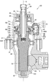
- FIG. 1 is a longitudinal sectional view of a power steering apparatus according to a first embodiment of the present invention.
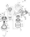
- FIG. 2 is an exploded perspective view of the power steering apparatus with the lower housing removed.
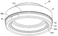
- FIG. 3A is a perspective view of a magnetism generator of the torque sensor according to the first embodiment.
- FIG. 3B is a bottom view of the magnetism generator of the torque sensor according to the first embodiment.
- FIG. 4 is a perspective view of the rotating magnetic circuit unit of the torque sensor according to the first embodiment.
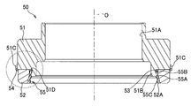
- FIG. 5A is a longitudinal sectional view of the magnetism generating portion.
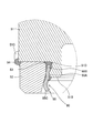
- FIG. 5B is an enlarged view of the magnetism generator in the broken line region of FIG. 5A.
- FIG. 6 is a vertical cross-sectional perspective view of the magnetism generator.
- FIG. 7A is a perspective view of a magnetism generator of the torque sensor according to the second embodiment.
- FIG. 7B is an exploded perspective view of a magnetism generator of the torque sensor according to the second embodiment.
- FIG. 8 is a bottom view of the magnetism generator of the torque sensor according to the second embodiment.
- FIG. 9A is a longitudinal cross-sectional view of the magnetism generating part in the AA plane of FIG.
- FIG. 9B is a vertical cross-sectional view of the magnetism generator in the BB plane of FIG.
- FIG. 10 is an enlarged view of the magnetism generator in the broken line region of FIG. 9B.
- a vehicle power steering apparatus 100 according to a first embodiment of the present invention will be described with reference to FIGS.
- the power steering apparatus 100 includes a steering shaft 10 that is linked to a steering wheel and a rack shaft 2 that is linked to a wheel. It is a device that moves and steers the wheel.
- Steering shaft 10 is a shaft member that is supported by upper housing 20 and lower housing 30 that are connected by bolts 21.
- the steering shaft 10 includes an input shaft 11 as a first shaft, a torsion bar 12, and an output shaft 13 as a second shaft.
- the input shaft 11 is rotatably supported by the upper housing 20 via a rolling bearing 22.
- a dust seal 23 seals between the input shaft 11 and the upper housing 20.
- the dust seal 23 is disposed above the rolling bearing 22.
- the output shaft 13 is rotatably supported by a rolling bearing 31 sandwiched between the lower end portion of the upper housing 20 and the upper end portion of the lower housing 30 and a sliding bearing 32 installed at the lower end portion of the lower housing 30.
- a housing chamber 13A capable of housing the lower end portion of the input shaft 11 is formed at the upper end portion of the output shaft 13.
- a sliding bearing 14 is interposed between the inner peripheral surface of the storage chamber 13 ⁇ / b> A of the output shaft 13 and the outer peripheral surface of the lower end portion of the input shaft 11.
- the input shaft 11 is formed in a cylindrical shape, and a torsion bar 12 is accommodated coaxially inside the input shaft 11.
- the upper end portion of the torsion bar 12 is connected to the upper end portion of the input shaft 11 via the pin 15.
- the lower end portion of the torsion bar 12 protrudes downward from the lower end opening portion of the input shaft 11.
- a serration 12 ⁇ / b> A is formed on the outer peripheral surface of the lower end portion of the torsion bar 12.
- the lower end of the torsion bar 12 is connected to an engagement hole 13B formed in the bottom of the storage chamber 13A via a serration 12A.
- the torsion bar 12 transmits a steering torque input to the input shaft 11 to the output shaft 13 and twists and deforms about the rotation axis O according to the torque.
- the output shaft 13 includes a gear 13C on the outer peripheral surface near the lower end.
- a gear 13 ⁇ / b> C of the output shaft 13 meshes with a rack gear 2 ⁇ / b> A formed on the rack shaft 2.
- the rack shaft 2 moves in the axial direction, and the wheels are steered.
- the power steering apparatus 100 includes a non-contact type torque sensor 40 that detects a steering torque that acts on the torsion bar 12 as an assist mechanism that supplementarily applies a steering torque, and a rack shaft 2 that corresponds to the detected steering torque. And an electric motor for applying steering assist torque.
- the torque sensor 40 includes a magnetism generating unit 50 that rotates with the input shaft 11, a rotating magnetic circuit unit 60 that rotates with the output shaft 13, a fixed magnetic circuit unit 70 that is fixed to the upper housing 20, and a fixed magnetic circuit unit 70. And a magnetic sensor 81 for detecting the guided magnetic flux density.
- the torque sensor 40 detects the steering torque acting on the torsion bar 12 based on the output of the magnetic sensor 81.
- the torque sensor 40 may have a configuration in which the output shaft 13 is provided with the magnetism generating unit 50 and the input shaft 11 is provided with the rotating magnetic circuit unit 60.
- the magnetism generator 50 includes an annular back yoke 51 press-fitted into the input shaft 11 and an annular back yoke 51 fixed to the lower end surface of the back yoke 51 via an adhesive.
- a ring magnet 52 is shown in FIG. 1, FIG. 3A and FIG. 3B.
- the ring magnet 52 is an annular permanent magnet.
- the ring magnet 52 is a multipolar magnet formed by magnetizing a hard magnetic material in the direction of the rotation axis O of the input shaft 11. As shown in FIG. 3B, twelve magnetic poles are formed at equal intervals in the circumferential direction on the ring magnet 52. That is, on the upper end surface and the lower end surface of the ring magnet 52, six N poles and six S poles are alternately arranged in the circumferential direction.
- the number of magnetic poles provided in the ring magnet 52 is not limited to 12 and can be arbitrarily set as necessary.
- the back yoke 51 is an annular member formed of a soft magnetic material.
- a ring magnet 52 is fixed to the lower end surface of the back yoke 51.
- the back yoke 51 has a function as a yoke that guides magnetic flux by connecting adjacent magnetic poles of the ring magnet 52, and concentrates the magnetic force on the lower magnetic pole surface that is the lower end surface of the ring magnet 52.
- the rotary magnetic circuit unit 60 is attached to the output shaft 13 and the first soft magnetic ring 61 and the second soft magnetic ring 62 that guide the magnetic flux emitted from the ring magnet 52.
- An attachment member 63 and a resin mold 64 for fixing the first soft magnetic ring 61 and the second soft magnetic ring 62 to the attachment member 63 are provided. In FIG. 4, the resin mold 64 is not shown.
- the first soft magnetic ring 61 includes an annular first magnetic path ring portion 61C, six first magnetic path column portions 61B protruding downward from the first magnetic path ring portion 61C, and each first magnetic path column portion.
- the second soft magnetic ring 62 includes an annular second magnetic path ring portion 62C, six second magnetic path column portions 62B protruding upward from the second magnetic path ring portion 62C, and each second magnetic path.
- a second magnetic path end portion 62A that refracts inward from the upper end of the column portion 62B and faces the lower end surface of the ring magnet 52.
- the first magnetic path ring portion 61C and the second magnetic path ring portion 62C are each an annular member having a whole circumference connected.
- the first magnetic path ring portion 61C and the second magnetic path ring portion 62C have a rotation axis so that the first magnetic path end portions 61A and the second magnetic path end portions 62A are alternately arranged at equal angular intervals on the same plane. Arranged at intervals in the O direction.
- the first magnetic path ring portion 61C is disposed above the lower end surface of the ring magnet 52, and the second magnetic path ring portion 62C is disposed below the ring magnet 52. Therefore, the ring magnet 52 is disposed between the first magnetic path ring portion 61C and the second magnetic path ring portion 62C in the direction of the rotation axis O of the torsion bar 12.
- the first magnetic path column portion 61B and the second magnetic path column portion 62B are each formed in a flat plate shape and extend in the direction of the rotation axis O.
- the first magnetic path column portion 61B is disposed so as to surround the outer peripheral surface of the ring magnet 52 with a predetermined gap.
- the second magnetic path column portion 62B extends along the rotation axis O in the direction opposite to the first magnetic path column portion 61B.
- the first magnetic path end 61A and the second magnetic path end 62A are each formed in a flat plate shape.
- the center lines of the first magnetic path end portion 61A and the second magnetic path end portion 62A indicate the boundary between the N pole and the S pole of the ring magnet 52. Is set to
- the fixed magnetic circuit portion 70 includes a first magnetic flux collecting ring 71 provided along the outer periphery of the first magnetic path ring portion 61 ⁇ / b> C of the first soft magnetic ring 61, and a second soft magnetic ring.
- the second magnetic flux collecting ring 72 provided along the outer periphery of the second magnetic path ring portion 62 ⁇ / b> C of the ring 62, the first magnetic flux collecting yoke 73 connected to the first magnetic flux collecting ring 71, and the second magnetic flux collecting ring 72 And a second magnetism collecting yoke 74 to be connected.
- the first magnetism collecting ring 71 and the second magnetism collecting ring 72 are caulked and fixed to the inner peripheral wall of the upper housing 20.
- the inner peripheral surface of the first magnetism collecting ring 71 faces the first magnetic path ring portion 61C of the first soft magnetic ring 61
- the inner peripheral surface of the second magnetism collecting ring 72 is the second magnetism of the second soft magnetic ring 62. It faces the road ring part 62C.
- the first magnetism collecting yoke 73 and the second magnetism collecting yoke 74 are block-shaped members.
- the first magnetism collecting yoke 73 is provided so as to contact the outer peripheral surface of the first magnetism collecting ring 71
- the second magnetism collecting yoke 74 is provided so as to contact the outer peripheral surface of the second magnetism collecting ring 72.
- a pair of magnetic gaps arranged in the circumferential direction is formed between the first magnetism collecting yoke 73 and the second magnetism collecting yoke 74.
- One magnetic sensor 81 is arranged in each magnetic gap.
- the first magnetic flux collecting yoke 73, the second magnetic flux collecting yoke 74, the magnetic sensor 81, and the substrate 82 connected to the magnetic sensor 81 are installed in the sensor holder 83.
- the resin sensor holder 83 is fixed to the metal upper housing 20 via a pair of bolts 84.
- the magnetic sensor 81 is a magnetic detector that detects a magnetic flux density guided from the magnetism generating unit 50 to the fixed magnetic circuit unit 70 through the rotating magnetic circuit unit 60 in accordance with the torsional deformation of the torsion bar 12.
- the magnetic sensor 81 outputs a voltage corresponding to the magnetic flux density passing through the Hall element as a signal.
- An output signal of the magnetic sensor 81 is transmitted to the controller via a terminal 83 ⁇ / b> A provided on the sensor holder 83.
- the magnetic sensor 81 may be provided with a circuit that amplifies the Hall element signal, a temperature compensation circuit, a noise filter circuit, or the like.
- the first magnetic path end 61A of the first soft magnetic ring 61 and the second magnetic path end 62A of the second soft magnetic ring 62 are respectively the N poles of the ring magnet 52. And the south pole are opposed to each other in the same area, and both poles are magnetically short-circuited. Therefore, the magnetic flux is not guided to the rotating magnetic circuit unit 60 and the fixed magnetic circuit unit 70.
- the torsion bar 12 When a steering torque in a specific direction is applied to the torsion bar 12 by the operation of the steering wheel by the driver, the torsion bar 12 is torsionally deformed according to the direction of the torque.
- the first magnetic path end 61A faces the N pole with a larger area than the S pole, while the second magnetic path end 62A has the S pole larger than the N pole. Confront.
- the magnetic flux from the ring magnet 52 is guided to the rotating magnetic circuit unit 60 and the fixed magnetic circuit unit 70, and the magnetic sensor 81 outputs a signal corresponding to the strength and direction of the magnetic field.
- the magnetic path in this case is from the N pole to the first soft magnetic ring 61, the first magnetic flux collecting ring 71, the first magnetic flux collecting yoke 73, the magnetic sensor 81, the second magnetic flux collecting yoke 74, the second magnetic flux collecting ring 72, This is a path toward the south pole via the two soft magnetic rings 62.
- the torsion bar 12 when a steering torque in the opposite direction to the above acts on the torsion bar 12 by the operation of the steering wheel by the driver, the torsion bar 12 is twisted and deformed in the opposite direction according to the direction of the torque.
- the first magnetic path end 61A faces the S pole with a larger area than the N pole, while the second magnetic path end 62A has a larger area with the N pole than the S pole.
- the magnetic flux from the ring magnet 52 is guided by a magnetic path opposite to the above magnetic path.
- the magnetic sensor 81 outputs a signal corresponding to the strength and direction of the magnetic field.
- the magnetic path is from the N pole to the second soft magnetic ring 62, the second magnetic flux collecting ring 72, the second magnetic flux collecting yoke 74, the magnetic sensor 81, the first magnetic flux collecting yoke 73, the first magnetic flux collecting ring 71, This is a path toward the south pole via one soft magnetic ring 61.
- the steering torque acting on the torsion bar is detected based on the signal output from the magnetic sensor 81.
- the back yoke 51 of the magnetism generator 50 is formed in an annular shape from an alloy of soft magnetic material.
- the back yoke 51 includes a fitting hole 51A that fits to the outer peripheral surface of the input shaft 11, a protruding portion 51B that protrudes downward from the lower end surface, and an engaging groove 51C formed on the outer peripheral surface.
- the fitting hole 51A is a hole that penetrates the back yoke 51 in the direction of the rotation axis O.
- the back yoke 51 is press-fitted into the outer peripheral surface of the input shaft 11 through the fitting hole 51A.
- the protrusion 51B is formed in an annular shape on the lower end surface of the back yoke 51.
- the inner diameter of the protruding portion 51B is set larger than the outer diameter of the input shaft 11 so that the input shaft 11 can be inserted.
- a recess 51D is formed to be recessed.
- the recess 51D is formed in the circumferential direction at a position near the lower end surface of the back yoke 51. That is, the recess 51D is an annular groove formed over the entire circumference at the upper outer periphery of the protrusion 51B.
- the recessed part 51D was provided over the perimeter of the outer peripheral surface of the protrusion part 51B, you may provide a some recessed part in the circumferential direction.
- the engaging groove 51 ⁇ / b> C is a vertical groove provided along the rotation axis O direction at the lower part of the outer peripheral surface of the back yoke 51.
- the engagement groove 51C extends from the lower end surface of the back yoke 51 to a predetermined position above the lower end surface.
- a plurality of engagement grooves 51 ⁇ / b> C are provided at equal intervals along the outer periphery of the back yoke 51. These engagement grooves 51C are formed by making the outer peripheral surface of the back yoke 51 uneven by knurling.
- the predetermined position where the engagement groove 51C is extended is appropriately changed as necessary.
- the engagement groove 51C may be extended to a predetermined position above. The effect of the linkage between the engagement groove 51C and the engagement surface 52B of the ring magnet 52 will be described later.
- the ring magnet 52 of the magnetism generating unit 50 is formed in an annular shape from a sintered metal.
- the ring magnet 52 is fixed to the lower end surface of the back yoke 51 via the bonding portions 53 and 54.
- the inner diameter of the ring magnet 52 is set larger than the outer diameter of the protruding portion 51B of the back yoke 51, and the ring magnet 52 is disposed so as to surround the protruding portion 51B. Therefore, the inner peripheral surface of the ring magnet 52 and the outer peripheral surface of the protrusion 51B are opposed to each other.
- a predetermined gap d is formed between the inner peripheral surface of the ring magnet 52 and the outer peripheral surface of the protruding portion 51B as shown in FIG. 5B.
- the protruding amount of the protruding portion 51B of the back yoke 51 is set to be approximately half the thickness of the ring magnet 52. Thereby, the magnetic short circuit between the lower end surface of the ring magnet 52 and the lower end surface of the protrusion part 51B is prevented.
- the protrusion amount of the protrusion 51B is not limited to approximately half the thickness of the ring magnet 52, and may be set to the same thickness of the ring magnet 52 or one third of the thickness, for example. That is, the protruding amount of the protruding portion 51B can be arbitrarily set as long as the protruding amount can prevent a magnetic short circuit between the lower end surface of the ring magnet 52 and the lower end surface of the protruding portion 51B.
- a concave portion (tapered portion) 52A cut out in a tapered shape is formed in the lower part of the inner peripheral surface of the ring magnet 52.
- the recess 52A is formed in a mortar shape so that the inner diameter of the ring magnet 52 gradually decreases from the lower end surface of the ring magnet 52 upward.
- the recess 52A is provided over a range from the lower end surface of the ring magnet 52 to a predetermined position corresponding to the lower end surface of the protruding portion 51B.
- the predetermined position corresponding to the lower end surface of the protruding portion 51B a position above the lower end surface of the protruding portion 51B and below the lower end of the recessed portion 51D is adopted.
- the present invention is not limited to this, and the predetermined position corresponding to the lower end surface of the protrusion 51B may be at least above the lower end surface of the protrusion 51B.
- an engagement surface 52B is provided on the outer peripheral surface of the ring magnet 52.
- the engagement surface 52B is a surface obtained by cutting out a part of the outer peripheral surface of the ring magnet 52.
- the engagement surface 52B is formed as a flat surface or a curved surface.
- the back yoke 51 and the ring magnet 52 described above are coupled through adhesive portions 53 and 54.
- the bonding parts 53 and 54 are solidified adhesives, and an elastic adhesive is used as the adhesives. Since the back yoke 51 is magnetized by the magnetic field of the ring magnet 52, the back yoke 51 and the ring magnet 52 are coupled not only by the adhesive force of the adhesive portions 53 and 54 but also by magnetic force.
- the adhesive portion 53 is an adhesive layer formed by solidifying the adhesive filled between the ring magnet 52 and the protruding portion 51 ⁇ / b> B.
- the bonding portion 53 is configured to reach the concave portion 51D of the protruding portion 51B and the concave portion 52A of the ring magnet 52 through the gap d between the inner peripheral surface of the ring magnet 52 and the outer peripheral surface of the protruding portion 51B.
- the adhesion part 53 is provided over the recessed part 52A of the ring magnet 52, the clearance gap d of the ring magnet 52 and the protrusion part 51B, and the recessed part 51D of the protrusion part 51B.
- the width of the predetermined gap d is set to be approximately the same as the maximum depth (maximum recess amount) of the recess 51D, but is not limited thereto. Even when the bonding portion 53 deteriorates and the bonding failure between the back yoke 51 and the ring magnet 52 occurs, the predetermined gap d causes the portion of the bonding portion 53 that has entered the concave portion 51D and the concave portion 52A of the bonding portion 53 to exist. It suffices that the bonding portion 53 is set to have a strength capable of holding the ring magnet 52 by the portion that has entered. Therefore, depending on the magnetic force and weight of the ring magnet 52 and the type of adhesive used for the bonding portion 53, the width of the predetermined gap d may be set wider or narrower than the maximum dent amount of the concave portion 51D. May be.
- the adhesive portion 54 is an adhesive layer in which an adhesive applied along the outer peripheral surface of the ring magnet 52 is solidified.
- the adhesion part 54 is provided over the upper end side outer periphery of the ring magnet 52 and the lower end side outer periphery of the back yoke 51 in which the engagement groove 51C is formed. As a result, the engagement surface 52B of the ring magnet 52 and the engagement groove 51C of the back yoke 51 are linked via the adhesive portion 54.
- the ring magnet 52 may fall off the back yoke 51.
- the adhesive portion 53 enters the concave portion 51D of the protruding portion 51B and the concave portion 52A of the ring magnet 52, the adhesive portion 53 itself is prevented from falling out of the protruding portion 51B, and the ring magnet 52 is interposed via the adhesive portion 53. Is prevented from falling off from the back yoke 51 in the direction of the rotation axis O. That is, since the ring magnet 52 is held by the bonding portion 53 that has entered the recess 52A of the ring magnet 52, the ring magnet 52 is prevented from falling off the back yoke 51.
- the ring magnet is attached to the back yoke 51 by the recess 51D of the protrusion 51B of the back yoke 51, the recess 52A of the ring magnet 52, the gap d between the protrusion 51B and the ring magnet 52, and the bonding portion 53.
- a holding mechanism 90 for holding 52 is formed. As described above, the holding mechanism 90 is provided between the protruding portion 51 ⁇ / b> B and the ring magnet 52.
- the adhesive portion 53 in a state of being caught in the concave portion 51D of the protruding portion 51B functions as a stopper that prevents the ring magnet 52 from falling off.
- the fixing position of the ring magnet 52 with respect to the back yoke 51 may be shifted around the rotation axis O.
- the bonding portion 54 is provided so as to link the engagement surface 52B of the ring magnet 52 and the engagement groove 51C of the back yoke 51, the rotation of the ring magnet 52 relative to the back yoke 51 is prevented.
- the rotation of the bonding portion 54 itself with respect to the back yoke 51 is restricted by the bonding portion 54 that has entered the engagement groove 51C of the back yoke 51, and the back yoke of the ring magnet 52 by the bonding portion 54 that is located on the engagement surface 52B of the ring magnet 52.
- the rotation with respect to 51 is restricted.
- the adhesive portion 54 that is locked to the outer periphery of the back yoke 51 functions as a stopper that restricts the rotation of the ring magnet 52.
- the adhesive portion 53 enters the concave portion 51D of the protruding portion 51B and the concave portion 52A of the ring magnet 52, and the ring magnet 52 enters the concave portion 52A. Since it is held by the bonding portion 53, it is possible to prevent the ring magnet 52 from falling off the back yoke 51.
- the bonding portion 54 is provided so as to link the engagement groove 51C of the back yoke 51 and the engagement surface 52B of the ring magnet 52, the rotation of the ring magnet 52 relative to the back yoke 51 can be prevented.
- the bonding portion 53 is provided so as to cover a part of the inner peripheral surface of the ring magnet 52, even if the ring magnet 52 is cracked in the portion covered by the bonding portion 53, the broken ring magnet 52 is scattered. Can be suppressed.
- the bonding portions 53 and 54 are made of an elastic adhesive, the impact force acting on the ring magnet 52 can be reduced.
- the protruding portion 51B is formed on the lower end surface near the inner periphery of the back yoke 51, but the protruding portion 51B may be formed on the lower end surface near the outer periphery of the back yoke 51.
- the outer diameter of the ring magnet 52 is made smaller than the inner diameter of the protruding portion 51B, and the ring magnet 52 is fixed to the lower end surface of the back yoke 51 inside the protruding portion 51B.
- a concave portion as an annular groove is formed in the inner peripheral upper portion of the protruding portion 51 ⁇ / b> B, and a concave portion is also formed in the lower peripheral portion of the ring magnet 52.
- the concave portion (tapered portion) of the ring magnet 52 is formed in a tapered shape so that the outer diameter of the ring magnet 52 gradually increases from the lower end surface of the ring magnet 52 upward.
- the bonding portion that couples the back yoke 51 and the ring magnet 52 is provided across the concave portion of the ring magnet 52, the gap between the ring magnet 52 and the protruding portion 51B, and the concave portion of the protruding portion 51B. Also with this configuration, the ring magnet 52 can be held by the bonding portion that has entered the recess of the ring magnet 52, and the ring magnet 52 can be prevented from falling off the back yoke 51.
- an engagement groove 51 ⁇ / b> C is provided along the outer peripheral surface of the back yoke 51, and an engagement surface 52 ⁇ / b> B is provided in a part of the outer peripheral surface of the ring magnet 52.
- an engagement groove as a vertical groove may be provided along the outer peripheral surface of the protrusion 51B, and an engagement surface as a notch surface may be provided on a part of the inner peripheral surface of the ring magnet 52.
- the adhesion part 53 provided in the inner peripheral side of the ring magnet 52 is provided so that the engagement groove
- the protrusion amount of the protrusion part 51B was set to about half of the thickness of the ring magnet 52, over the range from the lower end surface of the ring magnet 52 to the predetermined position corresponding to the lower end surface of the protrusion part 51B.
- the recess 52A is provided, the present invention is not limited to this.
- the protruding amount of the protruding portion 51B is set to be substantially the same as the thickness of the ring magnet 52, so-called chamfering formed on the outer peripheral corner portion on the lower end surface side and the inner peripheral corner portion on the upper end surface side of the ring magnet 52 is performed. Further, it may be formed on the inner peripheral corner portion on the lower end surface side of the ring magnet 52, and the chamfering of the inner peripheral corner portion may be used as the concave portion 52A.
- the bonding portion 54 is provided across the outer periphery of the ring magnet 52 and the outer periphery of the back yoke 51, but the bonding portion 54 is not necessarily provided. Even if the adhesive portion 54 is not provided, the torque sensor 40 can achieve the intended purpose.
- the protrusion 51B of the back yoke 51 constituting the torque sensor 40 of the power steering apparatus 200 has a gap d between the protrusion 51B and the ring magnet 52.
- a holding member 55 that holds the ring magnet 52 from the inside is attached.
- the holding member 55 constitutes a holding mechanism 90 that holds the ring magnet 52 on the back yoke 51.
- the holding member 55 is an annular member formed by pressing a nonmagnetic metal plate.
- the holding member 55 includes an annular main body portion 55A, an engaging portion 55B protruding inward from the main body portion 55A, and a holding portion 55C provided on the lower end surface of the main body portion 55A.
- the engaging portion 55B is a protruding piece protruding inside the main body portion 55A, and is formed so as to be cut out from the main body portion 55A.
- a pair of the engaging portions 55B are provided at axially symmetrical positions in the main body portion 55A.
- the two engaging portions 55B are formed in the main body portion 55A, but the number of engaging portions 55B is arbitrarily set as necessary.
- the holding portion 55C is a claw member (a protruding piece) protruding outward from the lower end surface of the main body portion 55A.
- the holding portions 55C are formed corresponding to the engaging portions 55B, and a pair of holding portions are provided at axially symmetrical positions in the main body portion 55A.
- the two holding portions 55C are formed in the main body portion 55A, but the number of the holding portions 55C is arbitrarily set as necessary.
- the holding member 55 is attached to the outer peripheral surface of the protruding portion 51B by engaging the engaging portion 55B with the concave portion 51D of the protruding portion 51B of the back yoke 51.
- a slit 55D (see FIG. 7B) that opens at a predetermined width in the circumferential direction is formed in the main body portion 55A of the holding member 55, and the main body portion 55A is engaged during the engaging operation for engaging the engaging portion 55B with the concave portion 51D.
- the inner diameter of the main body 55A can be finely adjusted.
- the ring magnet 52 is attached to the back yoke 51.
- the pair of holding portions 55 ⁇ / b> C of the holding member 55 are pushed and narrowed so as to approach each other, and the ring magnet 52 is disposed outside the holding member 55 in this state.
- An adhesive is applied to the upper end surface of the ring magnet 52, and the ring magnet 52 is attached to the lower end surface of the back yoke 51 through the adhesive.
- the holding portion 55 ⁇ / b> C After the ring magnet 52 is installed on the back yoke 51, the holding portion 55 ⁇ / b> C returns to the original position from the pressed state, and comes into contact with the concave portion (tapered portion) 52 ⁇ / b> A of the ring magnet 52.
- the holding member 55 holds the ring magnet 52 from the inside by the holding portion 55 ⁇ / b> C coming into contact with the recess 52 ⁇ / b> A of the ring magnet 52.
- an adhesive portion 53 is provided between the ring magnet 52 and the protruding portion 51B of the back yoke 51.
- the adhesive portion 53 is an adhesive layer formed by solidifying an adhesive filled in a gap between the ring magnet 52, the protruding portion 51B, and the holding member 55.
- the adhesion part 53 prevents rattling of the holding member 55 installed on the outer peripheral surface of the protruding part 51B and prevents the holding member 55 from coming off from the protruding part 51B.
- an adhesive portion 54 is provided across the outer periphery on the upper end side of the ring magnet 52 and the outer periphery on the lower end side of the back yoke 51 where the engagement groove 51C is formed.
- the adhesion portion 54 is an adhesion layer obtained by solidifying the adhesive applied to the outer peripheral surfaces of the back yoke 51 and the ring magnet 52.
- the adhesion part 54 is provided so that the engagement surface 52B of the ring magnet 52 and the engagement groove 51C of the back yoke 51 may be linked.
- the ring magnet 52 may drop from the back yoke 51 in the direction of the rotation axis O.
- the holding portion 55C of the holding member 55 abuts on the tapered concave portion 52A of the ring magnet 52, the holding member 55 holds the ring magnet 52 from the inside, so that the ring magnet 52 moves in the direction of the rotation axis O. Movement is restricted. Therefore, the ring magnet 52 is prevented from falling off from the back yoke 51 in the direction of the rotation axis O. By preventing the ring magnet 52 from falling off the back yoke 51, the detection accuracy of the torque sensor 40 is prevented from deteriorating.
- the bonding portion 54 is provided so as to link the engagement surface 52B of the ring magnet 52 and the engagement groove 51C of the back yoke 51, the rotation of the ring magnet 52 relative to the back yoke 51 is prevented.
- the rotation of the bonding portion 54 itself with respect to the back yoke 51 is restricted by the bonding portion 54 that has entered the engagement groove 51C of the back yoke 51, and the back yoke of the ring magnet 52 by the bonding portion 54 that is located on the engagement surface 52B of the ring magnet 52.
- the rotation with respect to 51 is restricted.
- the adhesive portion 54 that is locked to the outer periphery of the back yoke 51 functions as a stopper that restricts the rotation of the ring magnet 52.
- the holding portion 55C of the holding member 55 comes into contact with the concave portion (tapered portion) 52A of the ring magnet 52, so that the holding member 55 becomes the ring magnet 52. Since the ring magnet 52 is held from the inner side, the ring magnet 52 can be prevented from falling off from the back yoke 51.
- the bonding portion 54 is provided across the outer periphery of the back yoke 51 and the outer periphery of the ring magnet 52 so as to link the engagement groove 51C of the back yoke 51 and the engagement surface 52B of the ring magnet 52, The rotation of the ring magnet 52 can be prevented.
- the ring magnet 52 is provided so as to surround the outer periphery of the protruding portion 51B of the back yoke 51, and the holding member 55 is attached to the outer peripheral surface of the back yoke 51, but is limited to such a configuration. It is not something.
- the ring magnet 52 may be provided so as to be surrounded by the inner periphery of the protruding portion 51 ⁇ / b> B of the back yoke 51, and the holding member 55 may be attached to the inner peripheral surface of the back yoke 51.
- the bonding portion 54 is provided over the outer periphery of the ring magnet 52 and the outer periphery of the back yoke 51, but the bonding portion 54 is not necessarily provided. Even if the adhesive portion 54 is not provided, the torque sensor 40 can achieve the intended purpose.
Abstract
This torque sensor detects torque acting on a torsion bar on the basis of the magnetic flux density led to an affixed magnetic circuit unit through a rotating magnetic circuit unit from a magnetism generating unit in conjunction with the torsional deformation of a torsion bar. The magnetism generating unit is provided with: a back yoke fitted to the outside of a first shaft; an annular protrusion that is formed protruding from the back surface of the back yoke; an annular ring magnet provided to the end surface of the back yoke in a manner so as to have a predetermined gap to the protrusion; and a holding mechanism that is positioned in the gap and holds the ring magnet at the back yoke.
Description
本発明は、磁石から導かれる磁束密度に応じてシャフトに作用するトルクを検出するトルクセンサに関する。
The present invention relates to a torque sensor that detects a torque acting on a shaft in accordance with a magnetic flux density guided from a magnet.
JP2007-240496Aには、ステアリングシャフトに作用する操舵トルクを磁力によって検出する非接触タイプのトルクセンサが開示されている。このトルクセンサは、同軸上に配置される入力シャフトと出力シャフトとの間で操舵トルクを伝達するトーションバーと、入力シャフトに固定される磁気発生部と、出力シャフトに固定される回転磁気回路部と、ハウジングに固定される固定磁気回路部と、固定磁気回路部に導かれる磁束密度を検出する磁気センサと、を備える。磁気発生部は、入力シャフトに固定されるバックヨークと、接着剤を介してバックヨークに固定されるリング磁石とから構成されている。
JP 2007-240696A discloses a non-contact type torque sensor that detects a steering torque acting on a steering shaft by a magnetic force. The torque sensor includes a torsion bar that transmits a steering torque between an input shaft and an output shaft that are arranged on the same axis, a magnetism generating unit that is fixed to the input shaft, and a rotating magnetic circuit unit that is fixed to the output shaft. And a fixed magnetic circuit part fixed to the housing, and a magnetic sensor for detecting a magnetic flux density guided to the fixed magnetic circuit part. The magnetism generating unit includes a back yoke fixed to the input shaft and a ring magnet fixed to the back yoke via an adhesive.
トーションバーにトルクが作用してトーションバーがねじれ変形すると、磁気発生部と回転磁気回路部との回転方向の相対位置が変化する。これに伴い磁気発生部から回転磁気回路部を通じて固定磁気回路部に導かれる磁束密度が変化する。磁気センサは磁束密度に応じた信号を出力する。トーションバーに作用するトルクは、磁気センサから出力された信号に基づいて検出される。
¡When the torque acts on the torsion bar and the torsion bar twists and deforms, the relative position in the rotation direction between the magnetism generating portion and the rotating magnetic circuit portion changes. Along with this, the magnetic flux density guided from the magnetism generating unit to the fixed magnetic circuit unit through the rotating magnetic circuit unit changes. The magnetic sensor outputs a signal corresponding to the magnetic flux density. Torque acting on the torsion bar is detected based on a signal output from the magnetic sensor.
しかしながら、このような従来のトルクセンサでは、リング磁石とバックヨークとの間の接着不良が発生した場合に、外部からの衝撃等によってリング磁石がバックヨークから回転軸方向に脱落するおそれがある。
However, in such a conventional torque sensor, when a poor adhesion between the ring magnet and the back yoke occurs, the ring magnet may drop from the back yoke in the direction of the rotation axis due to an external impact or the like.
本発明は、上記の問題点に鑑みてなされたものであり、リング磁石とバックヨークとの間の接着不良が発生した場合であっても、リング磁石の脱落を防止することができるトルクセンサを提供することを目的とする。
The present invention has been made in view of the above problems, and a torque sensor that can prevent a ring magnet from falling off even when a poor adhesion between the ring magnet and the back yoke occurs. The purpose is to provide.
本発明のある態様によれば、ハウジング内に回転自在に支持された第1シャフトと第2シャフトとを連結するトーションバーに作用するトルクを検出するトルクセンサであって、前記第1シャフトに固定される磁気発生部と、前記第2シャフトに固定される回転磁気回路部と、前記ハウジングに固定される固定磁気回路部と、前記トーションバーのねじれ変形に伴って前記磁気発生部から前記回転磁気回路部を通じて前記固定磁気回路部に導かれる磁束密度を検出する磁気検出器と、を備え、前記磁気発生部は、前記第一シャフトに外嵌されるバックヨークと、前記バックヨークの端面に突出形成される環状の突出部と、前記突出部との間に所定の隙間を有するように前記バックヨークの端面に設けられる環状のリング磁石と、前記隙間に位置し、前記リング磁石を前記バックヨークに保持する保持機構と、を備えるトルクセンサが提供される。
According to an aspect of the present invention, there is provided a torque sensor that detects torque acting on a torsion bar that connects a first shaft and a second shaft that are rotatably supported in a housing, and is fixed to the first shaft. A magnetism generating portion, a rotating magnetic circuit portion fixed to the second shaft, a fixed magnetic circuit portion fixed to the housing, and the torsional deformation of the torsion bar from the magnetism generating portion to the rotating magnetism. A magnetic detector for detecting a magnetic flux density guided to the fixed magnetic circuit section through the circuit section, and the magnetism generating section projects from a back yoke fitted to the first shaft and an end surface of the back yoke. An annular ring magnet provided on an end surface of the back yoke so as to have a predetermined gap between the annular protrusion formed and the protrusion; and And location, a torque sensor and a holding mechanism for holding the ring magnet to the back yoke is provided.
本発明の実施形態及び利点については、添付された図面を参照しながら以下に詳細に説明する。
Embodiments and advantages of the present invention will be described in detail below with reference to the accompanying drawings.
図1~図6を参照して、本発明の第1実施形態による車両用のパワーステアリング装置100について説明する。
A vehicle power steering apparatus 100 according to a first embodiment of the present invention will be described with reference to FIGS.
図1及び図2に示すように、パワーステアリング装置100は、ステアリングホイールに連係するステアリングシャフト10と、車輪に連係するラック軸2とを備え、ステアリングシャフト10の回転によってラック軸2を軸方向に移動させて車輪を操舵する装置である。
As shown in FIGS. 1 and 2, the power steering apparatus 100 includes a steering shaft 10 that is linked to a steering wheel and a rack shaft 2 that is linked to a wheel. It is a device that moves and steers the wheel.
ステアリングシャフト10は、ボルト21によって連結される上部ハウジング20及び下部ハウジング30によって支持される軸部材である。ステアリングシャフト10は、第一シャフトとしての入力シャフト11と、トーションバー12と、第二シャフトとしての出力シャフト13と、を備える。
Steering shaft 10 is a shaft member that is supported by upper housing 20 and lower housing 30 that are connected by bolts 21. The steering shaft 10 includes an input shaft 11 as a first shaft, a torsion bar 12, and an output shaft 13 as a second shaft.
入力シャフト11は、転がり軸受22を介して上部ハウジング20に回転自在に支持される。入力シャフト11と上部ハウジング20との間はダストシール23によってシールされる。ダストシール23は、転がり軸受22の上方に配設されている。
The input shaft 11 is rotatably supported by the upper housing 20 via a rolling bearing 22. A dust seal 23 seals between the input shaft 11 and the upper housing 20. The dust seal 23 is disposed above the rolling bearing 22.
出力シャフト13は、上部ハウジング20の下端部及び下部ハウジング30の上端部に挟持される転がり軸受31と、下部ハウジング30の下端部に設置される滑り軸受32とによって、回転自在に支持される。
The output shaft 13 is rotatably supported by a rolling bearing 31 sandwiched between the lower end portion of the upper housing 20 and the upper end portion of the lower housing 30 and a sliding bearing 32 installed at the lower end portion of the lower housing 30.
出力シャフト13の上端部には、入力シャフト11の下端部を収容可能な収容室13Aが形成されている。出力シャフト13の収容室13Aの内周面と、入力シャフト11の下端部の外周面との間には、滑り軸受14が介装される。これにより、入力シャフト11及び出力シャフト13は、同一軸上で相対回転可能となっている。
A housing chamber 13A capable of housing the lower end portion of the input shaft 11 is formed at the upper end portion of the output shaft 13. A sliding bearing 14 is interposed between the inner peripheral surface of the storage chamber 13 </ b> A of the output shaft 13 and the outer peripheral surface of the lower end portion of the input shaft 11. Thereby, the input shaft 11 and the output shaft 13 are relatively rotatable on the same axis.
入力シャフト11は円筒状に形成されており、入力シャフト11の内部にはトーションバー12が同軸に収められる。トーションバー12の上端部は、ピン15を介して、入力シャフト11の上端部に連結される。トーションバー12の下端部は、入力シャフト11の下端開口部より下方に突出する。トーションバー12の下端部の外周面には、セレーション12Aが形成されている。トーションバー12の下端部は、セレーション12Aを介して、収容室13Aの底部に形成された係合孔13Bに連結される。トーションバー12は、入力シャフト11に入力される操舵トルクを出力シャフト13に伝達するとともに、そのトルクに応じて回転軸Oを中心にねじれ変形する。
The input shaft 11 is formed in a cylindrical shape, and a torsion bar 12 is accommodated coaxially inside the input shaft 11. The upper end portion of the torsion bar 12 is connected to the upper end portion of the input shaft 11 via the pin 15. The lower end portion of the torsion bar 12 protrudes downward from the lower end opening portion of the input shaft 11. A serration 12 </ b> A is formed on the outer peripheral surface of the lower end portion of the torsion bar 12. The lower end of the torsion bar 12 is connected to an engagement hole 13B formed in the bottom of the storage chamber 13A via a serration 12A. The torsion bar 12 transmits a steering torque input to the input shaft 11 to the output shaft 13 and twists and deforms about the rotation axis O according to the torque.
出力シャフト13は、下端寄りの外周面にギア13Cを備える。出力シャフト13のギア13Cは、ラック軸2に形成されたラックギア2Aと噛合する。入力シャフト11の回転に伴って出力シャフト13が回転することで、ラック軸2が軸方向に移動し、車輪が操舵される。
The output shaft 13 includes a gear 13C on the outer peripheral surface near the lower end. A gear 13 </ b> C of the output shaft 13 meshes with a rack gear 2 </ b> A formed on the rack shaft 2. As the output shaft 13 rotates as the input shaft 11 rotates, the rack shaft 2 moves in the axial direction, and the wheels are steered.
パワーステアリング装置100は、操舵トルクを補助的に付与するアシスト機構として、トーションバー12に作用する操舵トルクを検出する非接触式のトルクセンサ40と、検出された操舵トルクに応じてラック軸2に操舵補助トルクを付与する電動モータとを有している。
The power steering apparatus 100 includes a non-contact type torque sensor 40 that detects a steering torque that acts on the torsion bar 12 as an assist mechanism that supplementarily applies a steering torque, and a rack shaft 2 that corresponds to the detected steering torque. And an electric motor for applying steering assist torque.
トルクセンサ40は、入力シャフト11とともに回転する磁気発生部50と、出力シャフト13とともに回転する回転磁気回路部60と、上部ハウジング20に固定される固定磁気回路部70と、固定磁気回路部70に導かれる磁束密度を検出する磁気センサ81と、を備える。トルクセンサ40は、トーションバー12に作用する操舵トルクを磁気センサ81の出力に基づいて検出する。
The torque sensor 40 includes a magnetism generating unit 50 that rotates with the input shaft 11, a rotating magnetic circuit unit 60 that rotates with the output shaft 13, a fixed magnetic circuit unit 70 that is fixed to the upper housing 20, and a fixed magnetic circuit unit 70. And a magnetic sensor 81 for detecting the guided magnetic flux density. The torque sensor 40 detects the steering torque acting on the torsion bar 12 based on the output of the magnetic sensor 81.
なお、トルクセンサ40は、出力シャフト13に磁気発生部50を設け、入力シャフト11に回転磁気回路部60を設ける構成としてもよい。
The torque sensor 40 may have a configuration in which the output shaft 13 is provided with the magnetism generating unit 50 and the input shaft 11 is provided with the rotating magnetic circuit unit 60.
図1、図3A及び図3Bに示すように、磁気発生部50は、入力シャフト11に圧入される環状のバックヨーク51と、接着剤を介してバックヨーク51の下端面に固定される環状のリング磁石52と、を備える。
As shown in FIG. 1, FIG. 3A and FIG. 3B, the magnetism generator 50 includes an annular back yoke 51 press-fitted into the input shaft 11 and an annular back yoke 51 fixed to the lower end surface of the back yoke 51 via an adhesive. A ring magnet 52.
リング磁石52は、環状の永久磁石である。リング磁石52は、入力シャフト11の回転軸O方向へ向けて硬磁性体を着磁することによって形成される多極磁石である。図3Bに示すように、リング磁石52には、12個の磁極が周方向にわたって等間隔に形成される。つまり、リング磁石52の上端面及び下端面には、6個のN極と6個のS極が周方向に交互に配設される。リング磁石52に設けられる磁極数は、12個に限られず、必要に応じて任意に設定される。
The ring magnet 52 is an annular permanent magnet. The ring magnet 52 is a multipolar magnet formed by magnetizing a hard magnetic material in the direction of the rotation axis O of the input shaft 11. As shown in FIG. 3B, twelve magnetic poles are formed at equal intervals in the circumferential direction on the ring magnet 52. That is, on the upper end surface and the lower end surface of the ring magnet 52, six N poles and six S poles are alternately arranged in the circumferential direction. The number of magnetic poles provided in the ring magnet 52 is not limited to 12 and can be arbitrarily set as necessary.
バックヨーク51は、軟磁性体によって形成される環状部材である。バックヨーク51の下端面には、リング磁石52が固定される。バックヨーク51は、リング磁石52の隣り合う磁極を結んで磁束を導く継鉄としての機能を有しており、リング磁石52の下端面である下部磁極面に磁力を集中させる。
The back yoke 51 is an annular member formed of a soft magnetic material. A ring magnet 52 is fixed to the lower end surface of the back yoke 51. The back yoke 51 has a function as a yoke that guides magnetic flux by connecting adjacent magnetic poles of the ring magnet 52, and concentrates the magnetic force on the lower magnetic pole surface that is the lower end surface of the ring magnet 52.
図1、図2及び図4に示すように、回転磁気回路部60は、リング磁石52から出される磁束を導く第一軟磁性リング61及び第二軟磁性リング62と、出力シャフト13に取り付けられる取付部材63と、取付部材63に第一軟磁性リング61及び第二軟磁性リング62を固定する樹脂モールド64と、を備える。なお、図4においては、樹脂モールド64の記載が省略されている。
As shown in FIGS. 1, 2, and 4, the rotary magnetic circuit unit 60 is attached to the output shaft 13 and the first soft magnetic ring 61 and the second soft magnetic ring 62 that guide the magnetic flux emitted from the ring magnet 52. An attachment member 63 and a resin mold 64 for fixing the first soft magnetic ring 61 and the second soft magnetic ring 62 to the attachment member 63 are provided. In FIG. 4, the resin mold 64 is not shown.
第一軟磁性リング61は、環状の第一磁路環部61Cと、第一磁路環部61Cから下向きに突出する6個の第一磁路柱部61Bと、各第一磁路柱部61Bの下端からそれぞれ内向きに屈折してリング磁石52の下端面に対峙する第一磁路端部61Aと、を備える。また、第二軟磁性リング62は、環状の第二磁路環部62Cと、第二磁路環部62Cから上向きに突出する6個の第二磁路柱部62Bと、各第二磁路柱部62Bの上端からそれぞれ内向きに屈折して、リング磁石52の下端面に対峙する第二磁路端部62Aと、を備える。
The first soft magnetic ring 61 includes an annular first magnetic path ring portion 61C, six first magnetic path column portions 61B protruding downward from the first magnetic path ring portion 61C, and each first magnetic path column portion. A first magnetic path end 61 </ b> A that refracts inward from the lower end of 61 </ b> B and faces the lower end surface of the ring magnet 52. The second soft magnetic ring 62 includes an annular second magnetic path ring portion 62C, six second magnetic path column portions 62B protruding upward from the second magnetic path ring portion 62C, and each second magnetic path. A second magnetic path end portion 62A that refracts inward from the upper end of the column portion 62B and faces the lower end surface of the ring magnet 52.
第一磁路環部61C及び第二磁路環部62Cは、それぞれ全周がつながった環状部材である。第一磁路環部61C及び第二磁路環部62Cは、第一磁路端部61Aと第二磁路端部62Aとが同一面上において交互に等しい角度間隔で並ぶように、回転軸O方向に間隔をあけて配置される。
The first magnetic path ring portion 61C and the second magnetic path ring portion 62C are each an annular member having a whole circumference connected. The first magnetic path ring portion 61C and the second magnetic path ring portion 62C have a rotation axis so that the first magnetic path end portions 61A and the second magnetic path end portions 62A are alternately arranged at equal angular intervals on the same plane. Arranged at intervals in the O direction.
第一磁路環部61Cはリング磁石52の下端面より上方に配置され、第二磁路環部62Cはリング磁石52より下方に配置される。したがって、リング磁石52は、トーションバー12の回転軸O方向について第一磁路環部61Cと第二磁路環部62Cとの間に配置される。
The first magnetic path ring portion 61C is disposed above the lower end surface of the ring magnet 52, and the second magnetic path ring portion 62C is disposed below the ring magnet 52. Therefore, the ring magnet 52 is disposed between the first magnetic path ring portion 61C and the second magnetic path ring portion 62C in the direction of the rotation axis O of the torsion bar 12.
第一磁路柱部61Bと第二磁路柱部62Bは、それぞれ平板状に形成され、回転軸O方向に延設される。第一磁路柱部61Bは、所定の間隙をあけてリング磁石52の外周面を囲むように配置される。第二磁路柱部62Bは、回転軸Oに沿って第一磁路柱部61Bと反対方向に延設される。
The first magnetic path column portion 61B and the second magnetic path column portion 62B are each formed in a flat plate shape and extend in the direction of the rotation axis O. The first magnetic path column portion 61B is disposed so as to surround the outer peripheral surface of the ring magnet 52 with a predetermined gap. The second magnetic path column portion 62B extends along the rotation axis O in the direction opposite to the first magnetic path column portion 61B.
第一磁路端部61Aと第二磁路端部62Aは、それぞれ平板状に形成される。トーションバー12に操舵トルクが作用していない中立状態では、第一磁路端部61A及び第二磁路端部62Aの各中心線は、リング磁石52のN極とS極の境界を指すように設定されている。
The first magnetic path end 61A and the second magnetic path end 62A are each formed in a flat plate shape. In the neutral state where the steering torque is not applied to the torsion bar 12, the center lines of the first magnetic path end portion 61A and the second magnetic path end portion 62A indicate the boundary between the N pole and the S pole of the ring magnet 52. Is set to
図1及び図2に示すように、固定磁気回路部70は、第一軟磁性リング61の第一磁路環部61Cの外周に沿って設けられる第一集磁リング71と、第二軟磁性リング62の第二磁路環部62Cの外周に沿って設けられる第二集磁リング72と、第一集磁リング71に接続される第一集磁ヨーク73と、第二集磁リング72に接続される第二集磁ヨーク74と、を備える。
As shown in FIGS. 1 and 2, the fixed magnetic circuit portion 70 includes a first magnetic flux collecting ring 71 provided along the outer periphery of the first magnetic path ring portion 61 </ b> C of the first soft magnetic ring 61, and a second soft magnetic ring. The second magnetic flux collecting ring 72 provided along the outer periphery of the second magnetic path ring portion 62 </ b> C of the ring 62, the first magnetic flux collecting yoke 73 connected to the first magnetic flux collecting ring 71, and the second magnetic flux collecting ring 72 And a second magnetism collecting yoke 74 to be connected.
第一集磁リング71及び第二集磁リング72は、上部ハウジング20の内周壁にかしめ固定される。第一集磁リング71の内周面は第一軟磁性リング61の第一磁路環部61Cに対峙し、第二集磁リング72の内周面は第二軟磁性リング62の第二磁路環部62Cに対峙する。
The first magnetism collecting ring 71 and the second magnetism collecting ring 72 are caulked and fixed to the inner peripheral wall of the upper housing 20. The inner peripheral surface of the first magnetism collecting ring 71 faces the first magnetic path ring portion 61C of the first soft magnetic ring 61, and the inner peripheral surface of the second magnetism collecting ring 72 is the second magnetism of the second soft magnetic ring 62. It faces the road ring part 62C.
第一集磁ヨーク73及び第二集磁ヨーク74は、ブロック状の部材である。第一集磁ヨーク73は第一集磁リング71の外周面に当接するように設けられ、第二集磁ヨーク74は第二集磁リング72の外周面に当接するように設けられる。第一集磁ヨーク73と第二集磁ヨーク74との間には、周方向に並ぶ一対の磁気ギャップが形成される。各磁気ギャップ内には、磁気センサ81が一つずつ配置される。
The first magnetism collecting yoke 73 and the second magnetism collecting yoke 74 are block-shaped members. The first magnetism collecting yoke 73 is provided so as to contact the outer peripheral surface of the first magnetism collecting ring 71, and the second magnetism collecting yoke 74 is provided so as to contact the outer peripheral surface of the second magnetism collecting ring 72. A pair of magnetic gaps arranged in the circumferential direction is formed between the first magnetism collecting yoke 73 and the second magnetism collecting yoke 74. One magnetic sensor 81 is arranged in each magnetic gap.
第一集磁ヨーク73、第二集磁ヨーク74、磁気センサ81及び磁気センサ81と接続する基板82は、センサホルダ83に設置される。樹脂製のセンサホルダ83は、一対のボルト84を介して、金属製の上部ハウジング20に固定される。
The first magnetic flux collecting yoke 73, the second magnetic flux collecting yoke 74, the magnetic sensor 81, and the substrate 82 connected to the magnetic sensor 81 are installed in the sensor holder 83. The resin sensor holder 83 is fixed to the metal upper housing 20 via a pair of bolts 84.
磁気センサ81は、トーションバー12のねじれ変形に伴って磁気発生部50から回転磁気回路部60を通じて固定磁気回路部70に導かれる磁束密度を検出する磁気検出器である。磁気センサ81は、ホール素子を通過する磁束密度に応じた電圧を信号として出力する。磁気センサ81の出力信号は、センサホルダ83に設けられた端子83Aを介して、コントローラに送信される。なお、磁気センサ81には、ホール素子の信号を増幅する回路、温度補償を行う回路、又はノイズフィルタの回路等を設けてもよい。
The magnetic sensor 81 is a magnetic detector that detects a magnetic flux density guided from the magnetism generating unit 50 to the fixed magnetic circuit unit 70 through the rotating magnetic circuit unit 60 in accordance with the torsional deformation of the torsion bar 12. The magnetic sensor 81 outputs a voltage corresponding to the magnetic flux density passing through the Hall element as a signal. An output signal of the magnetic sensor 81 is transmitted to the controller via a terminal 83 </ b> A provided on the sensor holder 83. The magnetic sensor 81 may be provided with a circuit that amplifies the Hall element signal, a temperature compensation circuit, a noise filter circuit, or the like.
次に、トルクセンサ40がトーションバー12に作用する操舵トルクを検出する機能について説明する。
Next, the function that the torque sensor 40 detects the steering torque that acts on the torsion bar 12 will be described.
トーションバー12に操舵トルクが作用しない中立状態では、第一軟磁性リング61の第一磁路端部61A及び第二軟磁性リング62の第二磁路端部62Aはそれぞれリング磁石52のN極及びS極に同一の面積で対峙しており、両極は磁気短絡している。そのため、磁束は回転磁気回路部60と固定磁気回路部70に導かれない。
In the neutral state where the steering torque does not act on the torsion bar 12, the first magnetic path end 61A of the first soft magnetic ring 61 and the second magnetic path end 62A of the second soft magnetic ring 62 are respectively the N poles of the ring magnet 52. And the south pole are opposed to each other in the same area, and both poles are magnetically short-circuited. Therefore, the magnetic flux is not guided to the rotating magnetic circuit unit 60 and the fixed magnetic circuit unit 70.
運転者によるステアリングホイールの操作によって、トーションバー12に特定方向の操舵トルクが作用した場合には、このトルクの方向に応じてトーションバー12はねじれ変形する。トーションバー12がねじれ変形すると、第一磁路端部61AはS極よりN極に大きな面積を持って対峙する一方、第二磁路端部62AはN極よりS極に大きな面積を持って対峙する。リング磁石52からの磁束は回転磁気回路部60と固定磁気回路部70に導かれ、磁気センサ81は磁場の強さ及び方向に応じた信号を出力する。この場合における磁気経路は、N極から第一軟磁性リング61、第一集磁リング71、第一集磁ヨーク73、磁気センサ81、第二集磁ヨーク74、第二集磁リング72、第二軟磁性リング62を経由してS極に向かう経路である。
When a steering torque in a specific direction is applied to the torsion bar 12 by the operation of the steering wheel by the driver, the torsion bar 12 is torsionally deformed according to the direction of the torque. When the torsion bar 12 is torsionally deformed, the first magnetic path end 61A faces the N pole with a larger area than the S pole, while the second magnetic path end 62A has the S pole larger than the N pole. Confront. The magnetic flux from the ring magnet 52 is guided to the rotating magnetic circuit unit 60 and the fixed magnetic circuit unit 70, and the magnetic sensor 81 outputs a signal corresponding to the strength and direction of the magnetic field. The magnetic path in this case is from the N pole to the first soft magnetic ring 61, the first magnetic flux collecting ring 71, the first magnetic flux collecting yoke 73, the magnetic sensor 81, the second magnetic flux collecting yoke 74, the second magnetic flux collecting ring 72, This is a path toward the south pole via the two soft magnetic rings 62.
一方、運転者によるステアリングホイールの操作によって、トーションバー12に上記とは逆方向の操舵トルクが作用した場合には、このトルクの方向に応じてトーションバー12が逆方向にねじれ変形する。トーションバー12がねじれ変形すると、第一磁路端部61AはN極よりS極に大きな面積を持って対峙する一方、第二磁路端部62AはS極よりN極に大きな面積を持って対峙する。リング磁石52からの磁束は、上記の磁気経路と逆の磁気経路にて導かれる。磁気センサ81は、磁場の強さ及び方向に応じた信号を出力する。この場合における磁気経路は、N極から第二軟磁性リング62、第二集磁リング72、第二集磁ヨーク74、磁気センサ81、第一集磁ヨーク73、第一集磁リング71、第一軟磁性リング61を経由してS極に向かう経路である。
On the other hand, when a steering torque in the opposite direction to the above acts on the torsion bar 12 by the operation of the steering wheel by the driver, the torsion bar 12 is twisted and deformed in the opposite direction according to the direction of the torque. When the torsion bar 12 is torsionally deformed, the first magnetic path end 61A faces the S pole with a larger area than the N pole, while the second magnetic path end 62A has a larger area with the N pole than the S pole. Confront. The magnetic flux from the ring magnet 52 is guided by a magnetic path opposite to the above magnetic path. The magnetic sensor 81 outputs a signal corresponding to the strength and direction of the magnetic field. In this case, the magnetic path is from the N pole to the second soft magnetic ring 62, the second magnetic flux collecting ring 72, the second magnetic flux collecting yoke 74, the magnetic sensor 81, the first magnetic flux collecting yoke 73, the first magnetic flux collecting ring 71, This is a path toward the south pole via one soft magnetic ring 61.
第一磁路端部61Aがリング磁石52のN極とS極に対峙する面積差、及び第二磁路端部62Aがリング磁石52のN極とS極に対峙する面積差が大きいほど、磁気ギャップの磁場は強くなる。磁気ギャップにおける磁場が強くなると、磁気センサ81の出力信号も増大する。
The larger the area difference between the first magnetic path end 61A facing the N pole and the S pole of the ring magnet 52 and the second magnetic path end 62A facing the N pole and S pole of the ring magnet 52, The magnetic field of the magnetic gap becomes stronger. As the magnetic field in the magnetic gap becomes stronger, the output signal of the magnetic sensor 81 also increases.
トーションバーに作用する操舵トルクは、磁気センサ81から出力された信号に基づいて検出される。
The steering torque acting on the torsion bar is detected based on the signal output from the magnetic sensor 81.
次に、磁気発生部50のバックヨーク51及びリング磁石52の構成について説明する。
Next, the configuration of the back yoke 51 and the ring magnet 52 of the magnetism generator 50 will be described.
図3A、図5A及び図5Bに示すように、磁気発生部50のバックヨーク51は、軟磁性体の合金によって円環状に形成される。バックヨーク51は、入力シャフト11の外周面に対して嵌合する嵌合孔51Aと、下端面から下方に突出する突出部51Bと、外周面に形成される係合溝51Cと、を備える。
As shown in FIGS. 3A, 5A and 5B, the back yoke 51 of the magnetism generator 50 is formed in an annular shape from an alloy of soft magnetic material. The back yoke 51 includes a fitting hole 51A that fits to the outer peripheral surface of the input shaft 11, a protruding portion 51B that protrudes downward from the lower end surface, and an engaging groove 51C formed on the outer peripheral surface.
嵌合孔51Aは、バックヨーク51を回転軸O方向に貫通する孔である。バックヨーク51は、嵌合孔51Aを介して入力シャフト11の外周面に圧入される。
The fitting hole 51A is a hole that penetrates the back yoke 51 in the direction of the rotation axis O. The back yoke 51 is press-fitted into the outer peripheral surface of the input shaft 11 through the fitting hole 51A.
突出部51Bは、バックヨーク51の下端面に環状に形成される。突出部51Bの内径は、入力シャフト11が挿通可能なように、入力シャフト11の外径よりも大きく設定されている。突出部51Bの外周面には、凹部51Dが窪むように形成される。凹部51Dは、バックヨーク51の下端面寄りの位置において周方向に形成される。つまり、凹部51Dは、突出部51Bの外周上部において全周にわたって形成される環状溝である。
The protrusion 51B is formed in an annular shape on the lower end surface of the back yoke 51. The inner diameter of the protruding portion 51B is set larger than the outer diameter of the input shaft 11 so that the input shaft 11 can be inserted. On the outer peripheral surface of the protrusion 51B, a recess 51D is formed to be recessed. The recess 51D is formed in the circumferential direction at a position near the lower end surface of the back yoke 51. That is, the recess 51D is an annular groove formed over the entire circumference at the upper outer periphery of the protrusion 51B.
なお、バックヨーク51では、突出部51Bの外周面の全周にわたって凹部51Dを設けたが、周方向に複数の凹部を設けてもよい。
In addition, in the back yoke 51, although the recessed part 51D was provided over the perimeter of the outer peripheral surface of the protrusion part 51B, you may provide a some recessed part in the circumferential direction.
係合溝51Cは、バックヨーク51の外周面の下部に、回転軸O方向に沿って設けられる縦溝である。係合溝51Cは、バックヨーク51の下端面から、下端面よりも上方の所定位置まで延設される。係合溝51Cは、バックヨーク51の外周に沿って等間隔に複数設けられる。これら係合溝51Cは、ローレット加工によってバックヨーク51の外周面を凹凸状にすることで形成される。
The engaging groove 51 </ b> C is a vertical groove provided along the rotation axis O direction at the lower part of the outer peripheral surface of the back yoke 51. The engagement groove 51C extends from the lower end surface of the back yoke 51 to a predetermined position above the lower end surface. A plurality of engagement grooves 51 </ b> C are provided at equal intervals along the outer periphery of the back yoke 51. These engagement grooves 51C are formed by making the outer peripheral surface of the back yoke 51 uneven by knurling.
なお、係合溝51Cが延設される上記所定位置は必要に応じて適宜変更される。リング磁石52の周方向に加わる衝撃の大きさが大きいと想定される場合には、より上方の所定位置まで係合溝51Cを延設するとよい。係合溝51Cとリング磁石52の係合面52Bとの連係による作用効果については後述する。
Note that the predetermined position where the engagement groove 51C is extended is appropriately changed as necessary. When it is assumed that the magnitude of impact applied in the circumferential direction of the ring magnet 52 is large, the engagement groove 51C may be extended to a predetermined position above. The effect of the linkage between the engagement groove 51C and the engagement surface 52B of the ring magnet 52 will be described later.
図3A、図5A及び図5Bに示すように、磁気発生部50のリング磁石52は、焼結金属によって環状に形成される。リング磁石52は、接着部53、54を介して、バックヨーク51の下端面に固定される。リング磁石52の内径はバックヨーク51の突出部51Bの外径よりも大きく設定されており、リング磁石52は突出部51Bを取り囲むように配置される。したがって、リング磁石52の内周面と突出部51Bの外周面とは対向する。リング磁石52の内周面と突出部51Bの外周面との間には、図5Bに示すように所定の隙間dが形成される。
3A, 5A, and 5B, the ring magnet 52 of the magnetism generating unit 50 is formed in an annular shape from a sintered metal. The ring magnet 52 is fixed to the lower end surface of the back yoke 51 via the bonding portions 53 and 54. The inner diameter of the ring magnet 52 is set larger than the outer diameter of the protruding portion 51B of the back yoke 51, and the ring magnet 52 is disposed so as to surround the protruding portion 51B. Therefore, the inner peripheral surface of the ring magnet 52 and the outer peripheral surface of the protrusion 51B are opposed to each other. A predetermined gap d is formed between the inner peripheral surface of the ring magnet 52 and the outer peripheral surface of the protruding portion 51B as shown in FIG. 5B.
なお、バックヨーク51にリング磁石52が設置された状態で、バックヨーク51の突出部51Bの突出量は、リング磁石52の厚さの略半分となるように設定される。これにより、リング磁石52の下端面と突出部51Bの下端面の間における磁気短絡が防止される。
In the state where the ring magnet 52 is installed on the back yoke 51, the protruding amount of the protruding portion 51B of the back yoke 51 is set to be approximately half the thickness of the ring magnet 52. Thereby, the magnetic short circuit between the lower end surface of the ring magnet 52 and the lower end surface of the protrusion part 51B is prevented.
突出部51Bの突出量は、リング磁石52の厚さの略半分に限られず、例えばリング磁石52の厚さ同一又は厚さの3分の1等に設定してもよい。つまり、リング磁石52の下端面と突出部51Bの下端面との間における磁気短絡を防止することのできる突出量であれば、突出部51Bの突出量を任意に設定することができる。
The protrusion amount of the protrusion 51B is not limited to approximately half the thickness of the ring magnet 52, and may be set to the same thickness of the ring magnet 52 or one third of the thickness, for example. That is, the protruding amount of the protruding portion 51B can be arbitrarily set as long as the protruding amount can prevent a magnetic short circuit between the lower end surface of the ring magnet 52 and the lower end surface of the protruding portion 51B.
リング磁石52の内周面の下部には、テーパ状に切り欠かれた凹部(テーパ部)52Aが形成される。凹部52Aは、リング磁石52の内径がリング磁石52の下端面から上方に向かって徐々に縮径するように、すり鉢状に形成される。凹部52Aは、リング磁石52の下端面から突出部51Bの下端面に対応する所定位置までの範囲にわたって設けられる。
In the lower part of the inner peripheral surface of the ring magnet 52, a concave portion (tapered portion) 52A cut out in a tapered shape is formed. The recess 52A is formed in a mortar shape so that the inner diameter of the ring magnet 52 gradually decreases from the lower end surface of the ring magnet 52 upward. The recess 52A is provided over a range from the lower end surface of the ring magnet 52 to a predetermined position corresponding to the lower end surface of the protruding portion 51B.
なお、本実施形態では、突出部51Bの下端面に対応する所定位置として、突出部51Bの下端面より上方であり、かつ凹部51Dの下端よりも下方の位置を採用している。但し、これに限らず、突出部51Bの下端面に対応する所定位置は少なくとも突出部51Bの下端面より上方であればよい。
In the present embodiment, as the predetermined position corresponding to the lower end surface of the protruding portion 51B, a position above the lower end surface of the protruding portion 51B and below the lower end of the recessed portion 51D is adopted. However, the present invention is not limited to this, and the predetermined position corresponding to the lower end surface of the protrusion 51B may be at least above the lower end surface of the protrusion 51B.
また、リング磁石52の外周面には、係合面52Bが設けられる。係合面52Bは、リング磁石52の外周面の一部を切り欠いた面である。係合面52Bは、平面又は湾曲面として形成される。
Further, an engagement surface 52B is provided on the outer peripheral surface of the ring magnet 52. The engagement surface 52B is a surface obtained by cutting out a part of the outer peripheral surface of the ring magnet 52. The engagement surface 52B is formed as a flat surface or a curved surface.
上記したバックヨーク51及びリング磁石52は、接着部53、54を介して結合される。接着部53、54は固化後の接着剤であり、この接着剤には弾性接着剤が用いられる。バックヨーク51はリング磁石52の磁界によって磁化されるので、バックヨーク51及びリング磁石52は、接着部53、54の接着力だけでなく、磁力によっても結合される。
The back yoke 51 and the ring magnet 52 described above are coupled through adhesive portions 53 and 54. The bonding parts 53 and 54 are solidified adhesives, and an elastic adhesive is used as the adhesives. Since the back yoke 51 is magnetized by the magnetic field of the ring magnet 52, the back yoke 51 and the ring magnet 52 are coupled not only by the adhesive force of the adhesive portions 53 and 54 but also by magnetic force.
図5B及び図6に示すように、接着部53は、リング磁石52と突出部51Bの間に充填された接着剤が固化して形成された接着層である。接着部53は、リング磁石52の内周面と突出部51Bの外周面との間の隙間dを通じて、突出部51Bの凹部51D及びリング磁石52の凹部52Aに到達するように構成される。このように接着部53は、リング磁石52の凹部52Aと、リング磁石52及び突出部51Bの隙間dと、突出部51Bの凹部51Dとにわたって設けられる。
As shown in FIGS. 5B and 6, the adhesive portion 53 is an adhesive layer formed by solidifying the adhesive filled between the ring magnet 52 and the protruding portion 51 </ b> B. The bonding portion 53 is configured to reach the concave portion 51D of the protruding portion 51B and the concave portion 52A of the ring magnet 52 through the gap d between the inner peripheral surface of the ring magnet 52 and the outer peripheral surface of the protruding portion 51B. Thus, the adhesion part 53 is provided over the recessed part 52A of the ring magnet 52, the clearance gap d of the ring magnet 52 and the protrusion part 51B, and the recessed part 51D of the protrusion part 51B.
なお、本実施形態では、所定の隙間dの幅は、凹部51Dの最大深さ(最大凹み量)と略同一に設定されているが、これに限られない。所定の隙間dは、接着部53が劣化する等してバックヨーク51とリング磁石52との接着不良が発生した場合でも、接着部53の凹部51Dに入り込んだ部分及び接着部53の凹部52Aの入り込んだ部分によって接着部53がリング磁石52を保持可能な強度を有するように設定されていればよい。そのため、リング磁石52の磁力や重量、接着部53に使用する接着剤の種類等に応じて、所定の隙間dの幅を凹部51Dの最大凹み量よりも広く設定したり、狭く設定したりしてもよい。
In the present embodiment, the width of the predetermined gap d is set to be approximately the same as the maximum depth (maximum recess amount) of the recess 51D, but is not limited thereto. Even when the bonding portion 53 deteriorates and the bonding failure between the back yoke 51 and the ring magnet 52 occurs, the predetermined gap d causes the portion of the bonding portion 53 that has entered the concave portion 51D and the concave portion 52A of the bonding portion 53 to exist. It suffices that the bonding portion 53 is set to have a strength capable of holding the ring magnet 52 by the portion that has entered. Therefore, depending on the magnetic force and weight of the ring magnet 52 and the type of adhesive used for the bonding portion 53, the width of the predetermined gap d may be set wider or narrower than the maximum dent amount of the concave portion 51D. May be.
接着部54は、リング磁石52の外周面に沿って塗付された接着材が固化した接着層である。接着部54は、リング磁石52の上端側外周と、係合溝51Cが形成されるバックヨーク51の下端側外周とにわたって設けられる。これにより接着部54を介して、リング磁石52の係合面52Bとバックヨーク51の係合溝51Cとが連係する。
The adhesive portion 54 is an adhesive layer in which an adhesive applied along the outer peripheral surface of the ring magnet 52 is solidified. The adhesion part 54 is provided over the upper end side outer periphery of the ring magnet 52 and the lower end side outer periphery of the back yoke 51 in which the engagement groove 51C is formed. As a result, the engagement surface 52B of the ring magnet 52 and the engagement groove 51C of the back yoke 51 are linked via the adhesive portion 54.
次に、図5B及び図6を参照して、リング磁石52の脱落防止機能及び回転防止機能について説明する。
Next, with reference to FIG. 5B and FIG. 6, the drop prevention function and the rotation prevention function of the ring magnet 52 will be described.
仮に、接着部53、54が劣化する等してバックヨーク51とリング磁石52の接着不良が発生した場合には、リング磁石52とバックヨーク51の接合力のほとんどは磁力によるものとなる。
If bonding failure between the back yoke 51 and the ring magnet 52 occurs due to deterioration of the bonding portions 53 and 54, most of the bonding force between the ring magnet 52 and the back yoke 51 is due to magnetic force.
このような状態においてリング磁石52の軸方向に衝撃力が加わると、リング磁石52がバックヨーク51から脱落する可能性がある。しかしながら、接着部53が突出部51Bの凹部51D及びリング磁石52の凹部52Aに入り込んでいるので、接着部53自体が突出部51Bから抜け落ちることが防止され、この接着部53を介してリング磁石52がバックヨーク51から回転軸O方向に脱落することが防止される。つまり、リング磁石52はリング磁石52の凹部52Aに入り込んだ接着部53によって保持されるため、バックヨーク51からのリング磁石52の脱落が回避される。
In such a state, if an impact force is applied in the axial direction of the ring magnet 52, the ring magnet 52 may fall off the back yoke 51. However, since the adhesive portion 53 enters the concave portion 51D of the protruding portion 51B and the concave portion 52A of the ring magnet 52, the adhesive portion 53 itself is prevented from falling out of the protruding portion 51B, and the ring magnet 52 is interposed via the adhesive portion 53. Is prevented from falling off from the back yoke 51 in the direction of the rotation axis O. That is, since the ring magnet 52 is held by the bonding portion 53 that has entered the recess 52A of the ring magnet 52, the ring magnet 52 is prevented from falling off the back yoke 51.
第1実施形態では、バックヨーク51の突出部51Bの凹部51Dと、リング磁石52の凹部52Aと、突出部51B及びリング磁石52の隙間dと、接着部53とによって、バックヨーク51にリング磁石52を保持する保持機構90が形成される。このように保持機構90は、突出部51Bとリング磁石52との間に設けられる。
In the first embodiment, the ring magnet is attached to the back yoke 51 by the recess 51D of the protrusion 51B of the back yoke 51, the recess 52A of the ring magnet 52, the gap d between the protrusion 51B and the ring magnet 52, and the bonding portion 53. A holding mechanism 90 for holding 52 is formed. As described above, the holding mechanism 90 is provided between the protruding portion 51 </ b> B and the ring magnet 52.
上記の通り、突出部51Bの凹部51Dに引っ掛かった状態の接着部53がリング磁石52の脱落を防止するストッパとして機能する。バックヨーク51からのリング磁石52の脱落が回避されることで、トルクセンサ40の検出精度の悪化を防止できる。
As described above, the adhesive portion 53 in a state of being caught in the concave portion 51D of the protruding portion 51B functions as a stopper that prevents the ring magnet 52 from falling off. By avoiding the drop of the ring magnet 52 from the back yoke 51, it is possible to prevent the detection accuracy of the torque sensor 40 from deteriorating.
一方、リング磁石52の周方向に衝撃力が加わると、リング磁石52のバックヨーク51に対する固定位置が回転軸O周りにずれる可能性がある。しかしながら、接着部54はリング磁石52の係合面52Bとバックヨーク51の係合溝51Cとを連係するように設けられているため、バックヨーク51に対するリング磁石52の回転が防止される。バックヨーク51の係合溝51Cに入り込んだ接着部54によって接着部54自体のバックヨーク51に対する回転が規制され、リング磁石52の係合面52Bに位置する接着部54によってリング磁石52のバックヨーク51に対する回転が規制される。このようにバックヨーク51の外周に係止された状態の接着部54がリング磁石52の回転を規制するストッパとして機能する。バックヨーク51に対するリング磁石52の回転が回避されることによって、トルクセンサ40の検出精度の悪化が防止される。
On the other hand, when an impact force is applied in the circumferential direction of the ring magnet 52, the fixing position of the ring magnet 52 with respect to the back yoke 51 may be shifted around the rotation axis O. However, since the bonding portion 54 is provided so as to link the engagement surface 52B of the ring magnet 52 and the engagement groove 51C of the back yoke 51, the rotation of the ring magnet 52 relative to the back yoke 51 is prevented. The rotation of the bonding portion 54 itself with respect to the back yoke 51 is restricted by the bonding portion 54 that has entered the engagement groove 51C of the back yoke 51, and the back yoke of the ring magnet 52 by the bonding portion 54 that is located on the engagement surface 52B of the ring magnet 52. The rotation with respect to 51 is restricted. In this manner, the adhesive portion 54 that is locked to the outer periphery of the back yoke 51 functions as a stopper that restricts the rotation of the ring magnet 52. By avoiding rotation of the ring magnet 52 with respect to the back yoke 51, deterioration in detection accuracy of the torque sensor 40 is prevented.
上記した第1実施形態によるトルクセンサ40によれば、以下の効果を得ることができる。
According to the torque sensor 40 according to the first embodiment described above, the following effects can be obtained.
バックヨーク51とリング磁石52との間の接着不良が発生した場合でも、接着部53が突出部51Bの凹部51D及びリング磁石52の凹部52Aに入り込んでおり、リング磁石52は凹部52Aに入り込んだ接着部53によって保持されるので、バックヨーク51からのリング磁石52の脱落を防止することができる。
Even when a poor adhesion between the back yoke 51 and the ring magnet 52 occurs, the adhesive portion 53 enters the concave portion 51D of the protruding portion 51B and the concave portion 52A of the ring magnet 52, and the ring magnet 52 enters the concave portion 52A. Since it is held by the bonding portion 53, it is possible to prevent the ring magnet 52 from falling off the back yoke 51.
また、接着部54がバックヨーク51の係合溝51Cとリング磁石52の係合面52Bとを連係するように設けられるので、バックヨーク51に対するリング磁石52の回転を防止することができる。
Further, since the bonding portion 54 is provided so as to link the engagement groove 51C of the back yoke 51 and the engagement surface 52B of the ring magnet 52, the rotation of the ring magnet 52 relative to the back yoke 51 can be prevented.
接着部53はリング磁石52の内周面の一部を覆うように設けられるので、接着部53に覆われた部分においてリング磁石52に割れ等が発生しても、割れたリング磁石52が飛散することを抑制することができる。
Since the bonding portion 53 is provided so as to cover a part of the inner peripheral surface of the ring magnet 52, even if the ring magnet 52 is cracked in the portion covered by the bonding portion 53, the broken ring magnet 52 is scattered. Can be suppressed.
接着部53、54は弾性接着剤からなるので、リング磁石52に作用する衝撃力を低減することができる。
Since the bonding portions 53 and 54 are made of an elastic adhesive, the impact force acting on the ring magnet 52 can be reduced.
第1実施形態では、バックヨーク51の内周寄りの下端面に突出部51Bを形成したが、バックヨーク51の外周寄りの下端面に突出部51Bを形成してもよい。この場合には、リング磁石52の外径を突出部51Bの内径よりも小さくし、リング磁石52は突出部51Bの内側においてバックヨーク51の下端面に固定される。突出部51Bの内周上部には環状溝としての凹部が形成され、リング磁石52の外周下部にも凹部が形成される。リング磁石52の凹部(テーパ部)は、リング磁石52の外径がリング磁石52の下端面から上方に向かって徐々に拡径するようにテーパ状に形成される。バックヨーク51とリング磁石52とを結合する接着部は、リング磁石52の凹部と、リング磁石52と突出部51Bとの隙間と、突出部51Bの凹部とにわたって設けられる。このように構成することによっても、リング磁石52の凹部に入り込んだ接着部によってリング磁石52を保持でき、バックヨーク51からのリング磁石52の脱落を防止することができる。
In the first embodiment, the protruding portion 51B is formed on the lower end surface near the inner periphery of the back yoke 51, but the protruding portion 51B may be formed on the lower end surface near the outer periphery of the back yoke 51. In this case, the outer diameter of the ring magnet 52 is made smaller than the inner diameter of the protruding portion 51B, and the ring magnet 52 is fixed to the lower end surface of the back yoke 51 inside the protruding portion 51B. A concave portion as an annular groove is formed in the inner peripheral upper portion of the protruding portion 51 </ b> B, and a concave portion is also formed in the lower peripheral portion of the ring magnet 52. The concave portion (tapered portion) of the ring magnet 52 is formed in a tapered shape so that the outer diameter of the ring magnet 52 gradually increases from the lower end surface of the ring magnet 52 upward. The bonding portion that couples the back yoke 51 and the ring magnet 52 is provided across the concave portion of the ring magnet 52, the gap between the ring magnet 52 and the protruding portion 51B, and the concave portion of the protruding portion 51B. Also with this configuration, the ring magnet 52 can be held by the bonding portion that has entered the recess of the ring magnet 52, and the ring magnet 52 can be prevented from falling off the back yoke 51.
第1実施形態では、バックヨーク51の外周面に沿って係合溝51Cが設けられ、リング磁石52の外周面の一部に係合面52Bが設けられる。このような構成の代わりに、突出部51Bの外周面に沿って縦溝としての係合溝を設け、リング磁石52の内周面の一部に切欠面としての係合面を設けてもよい。この場合には、リング磁石52の内周側に設けられる接着部53が、突出部51Bの係合溝とリング磁石52の係合面とを連係するように設けられる。このように構成することによっても、バックヨーク51に対するリング磁石52の回転を防止することができる。
In the first embodiment, an engagement groove 51 </ b> C is provided along the outer peripheral surface of the back yoke 51, and an engagement surface 52 </ b> B is provided in a part of the outer peripheral surface of the ring magnet 52. Instead of such a configuration, an engagement groove as a vertical groove may be provided along the outer peripheral surface of the protrusion 51B, and an engagement surface as a notch surface may be provided on a part of the inner peripheral surface of the ring magnet 52. . In this case, the adhesion part 53 provided in the inner peripheral side of the ring magnet 52 is provided so that the engagement groove | channel of the protrusion part 51B and the engagement surface of the ring magnet 52 may be linked. Also with this configuration, the rotation of the ring magnet 52 relative to the back yoke 51 can be prevented.
また、第1実施形態では、突出部51Bの突出量をリング磁石52の厚さの略半分に設定したため、リング磁石52の下端面から突出部51Bの下端面に対応する所定位置までの範囲にわたって凹部52Aを設けたが、これに限られない。突出部51Bの突出量をリング磁石52の厚さと略同一に設定した場合には、リング磁石52の下端面側の外周角部及び上端面側の内周角部に形成されているいわゆる面取りを、リング磁石52の下端面側の内周角部にも形成し、内周角部の面取りを凹部52Aとして用いてもよい。
Moreover, in 1st Embodiment, since the protrusion amount of the protrusion part 51B was set to about half of the thickness of the ring magnet 52, over the range from the lower end surface of the ring magnet 52 to the predetermined position corresponding to the lower end surface of the protrusion part 51B. Although the recess 52A is provided, the present invention is not limited to this. When the protruding amount of the protruding portion 51B is set to be substantially the same as the thickness of the ring magnet 52, so-called chamfering formed on the outer peripheral corner portion on the lower end surface side and the inner peripheral corner portion on the upper end surface side of the ring magnet 52 is performed. Further, it may be formed on the inner peripheral corner portion on the lower end surface side of the ring magnet 52, and the chamfering of the inner peripheral corner portion may be used as the concave portion 52A.
さらに、第1実施形態では、リング磁石52の外周とバックヨーク51の外周とにわたって接着部54が設けられているが、接着部54は必ずしも設けられる必要はない。接着部54を備えていなくても、トルクセンサ40は所期の目的を達成することができる。
Furthermore, in the first embodiment, the bonding portion 54 is provided across the outer periphery of the ring magnet 52 and the outer periphery of the back yoke 51, but the bonding portion 54 is not necessarily provided. Even if the adhesive portion 54 is not provided, the torque sensor 40 can achieve the intended purpose.
次に、図7A~図10を参照して、本発明の第2実施形態による車両用のパワーステアリング装置200のトルクセンサ40について説明する。以下の図面においては、第1実施形態と同一の構成部分に第1実施形態と同一の符号を付している。
Next, the torque sensor 40 of the power steering apparatus 200 for a vehicle according to the second embodiment of the present invention will be described with reference to FIGS. 7A to 10. In the following drawings, the same reference numerals as those in the first embodiment are assigned to the same components as those in the first embodiment.
図7A、図7B、図9A及び図9Bに示すように、パワーステアリング装置200のトルクセンサ40を構成するバックヨーク51の突出部51Bには、突出部51Bとリング磁石52との間の隙間dを介して、リング磁石52を内側から保持する保持部材55が取り付けられる。この保持部材55が、バックヨーク51にリング磁石52を保持する保持機構90を構成している。
As shown in FIGS. 7A, 7B, 9A and 9B, the protrusion 51B of the back yoke 51 constituting the torque sensor 40 of the power steering apparatus 200 has a gap d between the protrusion 51B and the ring magnet 52. A holding member 55 that holds the ring magnet 52 from the inside is attached. The holding member 55 constitutes a holding mechanism 90 that holds the ring magnet 52 on the back yoke 51.
図7B、図8、図9A及び図9Bに示すように、保持部材55は、非磁性体の金属板をプレス加工によって形成した環状部材である。保持部材55は、環状の本体部55Aと、本体部55Aから内側に突出する係合部55Bと、本体部55Aの下端面に設けられる保持部55Cと、を備える。
7B, 8, 9A and 9B, the holding member 55 is an annular member formed by pressing a nonmagnetic metal plate. The holding member 55 includes an annular main body portion 55A, an engaging portion 55B protruding inward from the main body portion 55A, and a holding portion 55C provided on the lower end surface of the main body portion 55A.
係合部55Bは、本体部55Aの内側に突出する突出片であり、本体部55Aから切り出されるように形成されている。係合部55Bは、本体部55Aにおいて軸対称の位置に一対設けられる。本実施形態では本体部55Aに2つの係合部55Bを形成したが、係合部55Bの数は必要に応じて任意に設定される。
The engaging portion 55B is a protruding piece protruding inside the main body portion 55A, and is formed so as to be cut out from the main body portion 55A. A pair of the engaging portions 55B are provided at axially symmetrical positions in the main body portion 55A. In the present embodiment, the two engaging portions 55B are formed in the main body portion 55A, but the number of engaging portions 55B is arbitrarily set as necessary.
保持部55Cは、本体部55Aの下端面から外側に突出する爪部材(突出片)である。保持部55Cは、係合部55Bに対応して形成され、本体部55Aにおいて軸対称の位置に一対設けられる。本実施形態では本体部55Aに2つの保持部55Cを形成したが、保持部55Cの数は必要に応じて任意に設定される。
The holding portion 55C is a claw member (a protruding piece) protruding outward from the lower end surface of the main body portion 55A. The holding portions 55C are formed corresponding to the engaging portions 55B, and a pair of holding portions are provided at axially symmetrical positions in the main body portion 55A. In the present embodiment, the two holding portions 55C are formed in the main body portion 55A, but the number of the holding portions 55C is arbitrarily set as necessary.
保持部材55は、係合部55Bがバックヨーク51の突出部51Bの凹部51Dに係合することによって、突出部51Bの外周面に取り付けられる。保持部材55の本体部55Aには周方向にわたって所定幅で開口するスリット55D(図7B参照)が形成されており、本体部55Aは、係合部55Bを凹部51Dに係合させる係合作業時に本体部55Aの内径を微調整することができるよう構成されている。本体部55Aにスリット55Dを形成することで、係合部55Bと凹部51Dとの係合作業が容易になる。
The holding member 55 is attached to the outer peripheral surface of the protruding portion 51B by engaging the engaging portion 55B with the concave portion 51D of the protruding portion 51B of the back yoke 51. A slit 55D (see FIG. 7B) that opens at a predetermined width in the circumferential direction is formed in the main body portion 55A of the holding member 55, and the main body portion 55A is engaged during the engaging operation for engaging the engaging portion 55B with the concave portion 51D. The inner diameter of the main body 55A can be finely adjusted. By forming the slit 55D in the main body portion 55A, the engaging operation between the engaging portion 55B and the concave portion 51D is facilitated.
保持部材55をバックヨーク51の突出部51Bに設置した後に、リング磁石52がバックヨーク51に取り付けられる。リング磁石52を取り付ける際には、保持部材55の一対の保持部55Cを互いに近づくように押し狭め、この状態で保持部材55の外側にリング磁石52が配置される。リング磁石52の上端面には接着剤が塗付されており、接着剤を介してリング磁石52はバックヨーク51の下端面に取り付けられる。リング磁石52がバックヨーク51に設置された後、保持部55Cは押し狭められた状態から元の位置に戻り、リング磁石52の凹部(テーパ部)52Aに当接する。このように保持部55Cがリング磁石52の凹部52Aに当接することによって、保持部材55はリング磁石52を内側から保持する。
After the holding member 55 is installed on the protruding portion 51 </ b> B of the back yoke 51, the ring magnet 52 is attached to the back yoke 51. When attaching the ring magnet 52, the pair of holding portions 55 </ b> C of the holding member 55 are pushed and narrowed so as to approach each other, and the ring magnet 52 is disposed outside the holding member 55 in this state. An adhesive is applied to the upper end surface of the ring magnet 52, and the ring magnet 52 is attached to the lower end surface of the back yoke 51 through the adhesive. After the ring magnet 52 is installed on the back yoke 51, the holding portion 55 </ b> C returns to the original position from the pressed state, and comes into contact with the concave portion (tapered portion) 52 </ b> A of the ring magnet 52. Thus, the holding member 55 holds the ring magnet 52 from the inside by the holding portion 55 </ b> C coming into contact with the recess 52 </ b> A of the ring magnet 52.
図9A及び図9Bに示すように、リング磁石52とバックヨーク51の突出部51Bとの間には、接着部53が設けられる。接着部53は、リング磁石52、突出部51B、及び保持部材55の間の隙間に充填された接着剤が固化して形成された接着層である。接着部53は、突出部51Bの外周面に設置された保持部材55のがたつきを防止するとともに、突出部51Bからの保持部材55の抜けを防止する。
9A and 9B, an adhesive portion 53 is provided between the ring magnet 52 and the protruding portion 51B of the back yoke 51. The adhesive portion 53 is an adhesive layer formed by solidifying an adhesive filled in a gap between the ring magnet 52, the protruding portion 51B, and the holding member 55. The adhesion part 53 prevents rattling of the holding member 55 installed on the outer peripheral surface of the protruding part 51B and prevents the holding member 55 from coming off from the protruding part 51B.
また、リング磁石52の上端側外周と、係合溝51Cが形成されるバックヨーク51の下端側外周とにわたって、接着部54が設けられる。接着部54は、バックヨーク51及びリング磁石52の外周面に塗付された接着材が固化した接着層である。接着部54は、リング磁石52の係合面52Bとバックヨーク51の係合溝51Cとを連係するように設けられている。
Also, an adhesive portion 54 is provided across the outer periphery on the upper end side of the ring magnet 52 and the outer periphery on the lower end side of the back yoke 51 where the engagement groove 51C is formed. The adhesion portion 54 is an adhesion layer obtained by solidifying the adhesive applied to the outer peripheral surfaces of the back yoke 51 and the ring magnet 52. The adhesion part 54 is provided so that the engagement surface 52B of the ring magnet 52 and the engagement groove 51C of the back yoke 51 may be linked.
次に、図9A、図9B及び図10を参照して、リング磁石52の脱落防止機能及び回転防止機能について説明する。
Next, with reference to FIG. 9A, FIG. 9B, and FIG. 10, the drop prevention function and the rotation prevention function of the ring magnet 52 will be described.
バックヨーク51とリング磁石52とを接合する接着剤が劣化等して、バックヨーク51及びリング磁石52の接着不良が発生した場合には、リング磁石52とバックヨーク51の接合力のほとんどは磁力によるものとなる。
When a bonding failure between the back yoke 51 and the ring magnet 52 occurs due to deterioration of the adhesive for joining the back yoke 51 and the ring magnet 52, most of the joining force between the ring magnet 52 and the back yoke 51 is a magnetic force. It will be due to.
このような状態においてパワーステアリング装置200に回転軸O方向の衝撃力が加わると、リング磁石52がバックヨーク51から回転軸O方向に脱落する可能性がある。
In such a state, if an impact force in the direction of the rotation axis O is applied to the power steering apparatus 200, the ring magnet 52 may drop from the back yoke 51 in the direction of the rotation axis O.
しかしながら、保持部材55の保持部55Cがリング磁石52のテーパ状の凹部52Aに当接することで、保持部材55がリング磁石52を内側から保持しているので、リング磁石52が回転軸O方向に移動することが規制される。したがって、リング磁石52がバックヨーク51から回転軸O方向に脱落することが防止される。バックヨーク51からのリング磁石52の脱落が回避されることによって、トルクセンサ40の検出精度の悪化が防止される。
However, since the holding portion 55C of the holding member 55 abuts on the tapered concave portion 52A of the ring magnet 52, the holding member 55 holds the ring magnet 52 from the inside, so that the ring magnet 52 moves in the direction of the rotation axis O. Movement is restricted. Therefore, the ring magnet 52 is prevented from falling off from the back yoke 51 in the direction of the rotation axis O. By preventing the ring magnet 52 from falling off the back yoke 51, the detection accuracy of the torque sensor 40 is prevented from deteriorating.
一方、パワーステアリング装置200に回転軸O周りの衝撃力が加わると、リング磁石52のバックヨーク51に対する固定位置が回転軸O周りにずれる可能性がある。
On the other hand, when an impact force around the rotation axis O is applied to the power steering device 200, the fixing position of the ring magnet 52 with respect to the back yoke 51 may shift around the rotation axis O.
しかしながら、接着部54はリング磁石52の係合面52Bとバックヨーク51の係合溝51Cとを連係するように設けられているため、バックヨーク51に対するリング磁石52の回転が防止される。バックヨーク51の係合溝51Cに入り込んだ接着部54によって接着部54自体のバックヨーク51に対する回転が規制され、リング磁石52の係合面52Bに位置する接着部54によってリング磁石52のバックヨーク51に対する回転が規制される。このように、バックヨーク51の外周に係止された状態の接着部54がリング磁石52の回転を規制するストッパとして機能する。バックヨーク51に対するリング磁石52の回転が回避されることによって、トルクセンサ40の検出精度の悪化が防止される。
However, since the bonding portion 54 is provided so as to link the engagement surface 52B of the ring magnet 52 and the engagement groove 51C of the back yoke 51, the rotation of the ring magnet 52 relative to the back yoke 51 is prevented. The rotation of the bonding portion 54 itself with respect to the back yoke 51 is restricted by the bonding portion 54 that has entered the engagement groove 51C of the back yoke 51, and the back yoke of the ring magnet 52 by the bonding portion 54 that is located on the engagement surface 52B of the ring magnet 52. The rotation with respect to 51 is restricted. As described above, the adhesive portion 54 that is locked to the outer periphery of the back yoke 51 functions as a stopper that restricts the rotation of the ring magnet 52. By avoiding rotation of the ring magnet 52 with respect to the back yoke 51, deterioration in detection accuracy of the torque sensor 40 is prevented.
上記した第2実施形態によるトルクセンサ40によれば、以下の効果を得ることができる。
According to the torque sensor 40 according to the second embodiment described above, the following effects can be obtained.
バックヨーク51とリング磁石52との間の接着不良が発生した場合でも、保持部材55の保持部55Cがリング磁石52の凹部(テーパ部)52Aに当接することで、保持部材55がリング磁石52を内側から保持しているので、バックヨーク51からのリング磁石52の脱落を防止することができる。
Even when poor adhesion between the back yoke 51 and the ring magnet 52 occurs, the holding portion 55C of the holding member 55 comes into contact with the concave portion (tapered portion) 52A of the ring magnet 52, so that the holding member 55 becomes the ring magnet 52. Since the ring magnet 52 is held from the inner side, the ring magnet 52 can be prevented from falling off from the back yoke 51.
また、バックヨーク51の係合溝51Cとリング磁石52の係合面52Bとを連係するように接着部54がバックヨーク51の外周とリング磁石52の外周とにわたって設けられるので、バックヨーク51に対するリング磁石52の回転を防止することができる。
Further, since the bonding portion 54 is provided across the outer periphery of the back yoke 51 and the outer periphery of the ring magnet 52 so as to link the engagement groove 51C of the back yoke 51 and the engagement surface 52B of the ring magnet 52, The rotation of the ring magnet 52 can be prevented.
第2実施形態では、リング磁石52はバックヨーク51の突出部51Bの外周を取り囲むように設けられ、保持部材55はバックヨーク51の外周面に取り付けられているが、このような構成に限定されるものではない。バックヨーク51の突出部51Bの内周によって取り囲まれるようにリング磁石52を設け、バックヨーク51の内周面に保持部材55を取り付けるようにしてもよい。
In the second embodiment, the ring magnet 52 is provided so as to surround the outer periphery of the protruding portion 51B of the back yoke 51, and the holding member 55 is attached to the outer peripheral surface of the back yoke 51, but is limited to such a configuration. It is not something. The ring magnet 52 may be provided so as to be surrounded by the inner periphery of the protruding portion 51 </ b> B of the back yoke 51, and the holding member 55 may be attached to the inner peripheral surface of the back yoke 51.
また、第2実施形態では、リング磁石52の外周とバックヨーク51の外周とにわたって接着部54が設けられているが、接着部54は必ずしも設けられる必要はない。接着部54を備えていなくても、トルクセンサ40は所期の目的を達成することができる。
In the second embodiment, the bonding portion 54 is provided over the outer periphery of the ring magnet 52 and the outer periphery of the back yoke 51, but the bonding portion 54 is not necessarily provided. Even if the adhesive portion 54 is not provided, the torque sensor 40 can achieve the intended purpose.
以上、本発明の実施形態について説明したが、上記実施形態は本発明の適用例の一部を示したに過ぎず、本発明の技術的範囲を上記実施形態の具体的構成に限定する趣旨ではない。
The embodiment of the present invention has been described above. However, the above embodiment only shows a part of application examples of the present invention, and the technical scope of the present invention is limited to the specific configuration of the above embodiment. Absent.
本願は2011年3月18日に日本国特許庁に出願された特願2011-60226及び2011年3月18日に日本国特許庁に出願された特願2011-60227に基づく優先権を主張し、これら出願の全ての内容は参照により本明細書に組み込まれる。
This application claims priority based on Japanese Patent Application No. 2011-60226 filed with the Japan Patent Office on March 18, 2011 and Japanese Patent Application No. 2011-60227 filed with the Japan Patent Office on March 18, 2011. The entire contents of these applications are hereby incorporated by reference.
Claims (14)
- ハウジング内に回転自在に支持された第1シャフトと第2シャフトとを連結するトーションバーに作用するトルクを検出するトルクセンサであって、
前記第1シャフトに固定される磁気発生部と、
前記第2シャフトに固定される回転磁気回路部と、
前記ハウジングに固定される固定磁気回路部と、
前記トーションバーのねじれ変形に伴って前記磁気発生部から前記回転磁気回路部を通じて前記固定磁気回路部に導かれる磁束密度を検出する磁気検出器と、を備え、
前記磁気発生部は、
前記第一シャフトに外嵌されるバックヨークと、
前記バックヨークの端面に突出形成される環状の突出部と、
前記突出部との間に所定の隙間を有するように前記バックヨークの端面に設けられる環状のリング磁石と、
前記隙間に位置し、前記リング磁石を前記バックヨークに保持する保持機構と、を備えるトルクセンサ。 A torque sensor for detecting a torque acting on a torsion bar connecting the first shaft and the second shaft rotatably supported in the housing;
A magnetic generator fixed to the first shaft;
A rotating magnetic circuit portion fixed to the second shaft;
A fixed magnetic circuit portion fixed to the housing;
A magnetic detector for detecting a magnetic flux density guided from the magnetism generating unit to the fixed magnetic circuit unit through the rotating magnetic circuit unit in accordance with the torsional deformation of the torsion bar;
The magnetism generator is
A back yoke fitted over the first shaft;
An annular protrusion formed on the end surface of the back yoke;
An annular ring magnet provided on the end face of the back yoke so as to have a predetermined gap between the protrusion and
A torque sensor comprising: a holding mechanism that is located in the gap and holds the ring magnet on the back yoke. - 請求項1に記載のトルクセンサであって、
前記保持機構は、
前記突出部の前記リング磁石と対向する側面に設けられる第一凹部と、
前記リング磁石の前記突出部と対向する側面に設けられる第二凹部と、
前記隙間、前記第一凹部、及び前記第二凹部にわたって設けられ、前記バックヨークと前記リング磁石とを接着する主接着部と、を備えるトルクセンサ。 The torque sensor according to claim 1,
The holding mechanism is
A first recess provided on a side surface of the protruding portion facing the ring magnet;
A second recess provided on a side surface of the ring magnet facing the protruding portion;
A torque sensor provided with a main adhesion part which is provided over the crevice, the 1st crevice, and the 2nd crevice, and adheres the back yoke and the ring magnet. - 請求項2に記載のトルクセンサであって、
前記リング磁石は、前記突出部の外周を取り囲むように設けられ、
前記第一凹部は、前記突出部の外周に沿って形成され、
前記第二凹部は、前記リング磁石の内周に沿って形成されるトルクセンサ。 The torque sensor according to claim 2,
The ring magnet is provided so as to surround the outer periphery of the protrusion,
The first recess is formed along the outer periphery of the protrusion,
The second recess is a torque sensor formed along the inner periphery of the ring magnet. - 請求項3に記載のトルクセンサであって、
前記第一凹部は、前記バックヨークの端面寄りの位置に設けられる環状溝であり、
前記第二凹部は、前記リング磁石の内径がリング磁石の端面から前記突出部に向かって縮径するようにテーパ状に形成されるトルクセンサ。 The torque sensor according to claim 3,
The first recess is an annular groove provided at a position near the end face of the back yoke,
The second recess is a torque sensor formed in a tapered shape so that an inner diameter of the ring magnet is reduced from an end surface of the ring magnet toward the protrusion. - 請求項3に記載のトルクセンサであって、
前記バックヨークの外周に沿って設けられ、軸方向に沿って延設される係合溝と、
前記リング磁石の外周の一部を切り欠いて設けられる係合面と、
前記係合溝と前記係合面とを連係させるように前記バックヨークの外周と前記リング磁石の外周とにわたって設けられ、前記バックヨークと前記リング磁石とを接着する副接着部と、をさらに備えるトルクセンサ。 The torque sensor according to claim 3,
An engagement groove provided along the outer periphery of the back yoke and extending along the axial direction;
An engagement surface provided by cutting out a part of the outer periphery of the ring magnet;
A sub-adhesion part that is provided across the outer periphery of the back yoke and the outer periphery of the ring magnet so as to link the engagement groove and the engagement surface, and that bonds the back yoke and the ring magnet; Torque sensor. - 請求項5に記載のトルクセンサであって、
前記係合溝は、前記バックヨークの外周面に沿って複数設けられ、
前記係合面は、平面又は湾曲面として形成されるトルクセンサ。 The torque sensor according to claim 5,
A plurality of the engaging grooves are provided along the outer peripheral surface of the back yoke,
The engagement surface is a torque sensor formed as a flat surface or a curved surface. - 請求項1に記載のトルクセンサであって、
前記保持機構は、前記隙間内において前記突出部に取り付けられ、前記リング磁石を保持するように構成された保持部材であるトルクセンサ。 The torque sensor according to claim 1,
The said holding mechanism is a torque sensor which is a holding member attached to the said protrusion part in the said clearance gap, and comprised so that the said ring magnet might be hold | maintained. - 請求項7に記載のトルクセンサであって、
前記リング磁石は、前記突出部の外周を取り囲むように設けられ、
前記保持部材は、前記突出部の外周面に取り付けられるトルクセンサ。 The torque sensor according to claim 7,
The ring magnet is provided so as to surround the outer periphery of the protrusion,
The holding member is a torque sensor attached to an outer peripheral surface of the protrusion. - 請求項8に記載のトルクセンサであって、
前記リング磁石の内周面には、前記リング磁石の端面から前記バックヨークの端面に向かって縮径されるテーパ部が形成され、
前記保持部材は、前記テーパ部に当接することで、前記リング磁石を内側から保持する保持部を備えるトルクセンサ。 The torque sensor according to claim 8,
On the inner peripheral surface of the ring magnet, a tapered portion that is reduced in diameter from the end surface of the ring magnet toward the end surface of the back yoke is formed.
The said holding member is a torque sensor provided with the holding part which hold | maintains the said ring magnet from an inner side by contact | abutting to the said taper part. - 請求項9に記載のトルクセンサであって、
前記突出部の外周面には周方向に沿って凹部が形成され、
前記保持部材は、前記凹部に係合することで、前記保持部材を前記突出部に設置する係合部を備えるトルクセンサ。 The torque sensor according to claim 9, wherein
A concave portion is formed along the circumferential direction on the outer peripheral surface of the protruding portion,
The said holding member is a torque sensor provided with the engaging part which installs the said holding member in the said protrusion part by engaging with the said recessed part. - 請求項10に記載のトルクセンサであって、
前記保持部材は、前記保持部及び前記係合部を有する環状の本体部を備え、
前記本体部は、周方向にわたって所定幅で開口するスリットを備えるトルクセンサ。 The torque sensor according to claim 10, wherein
The holding member includes an annular main body having the holding portion and the engaging portion,
The said main-body part is a torque sensor provided with the slit opened by the predetermined width over the circumferential direction. - 請求項8に記載のトルクセンサであって、
前記保持部材が設けられる前記突出部と前記リング磁石との間には、接着層が形成されるトルクセンサ。 The torque sensor according to claim 8,
A torque sensor in which an adhesive layer is formed between the protrusion provided with the holding member and the ring magnet. - 請求項8に記載のトルクセンサであって、
前記バックヨークの外周面に設けられ、軸方向に沿って延設される係合溝と、
前記リング磁石の外周の一部を切り欠いて設けられる係合面と、
前記係合溝と前記係合面とを連係させるように前記バックヨークの外周面と前記リング磁石の外周面とにわたって設けられる接着部と、を備えるトルクセンサ。 The torque sensor according to claim 8,
An engagement groove provided on the outer peripheral surface of the back yoke and extending along the axial direction;
An engagement surface provided by cutting out a part of the outer periphery of the ring magnet;
A torque sensor comprising: an adhesive portion provided across an outer peripheral surface of the back yoke and an outer peripheral surface of the ring magnet so as to link the engaging groove and the engaging surface. - 請求項13に記載のトルクセンサであって、
前記係合溝は、前記バックヨークの外周面に沿って複数設けられ、
前記係合面は、平面又は湾曲面として形成されるトルクセンサ。 The torque sensor according to claim 13,
A plurality of the engaging grooves are provided along the outer peripheral surface of the back yoke,
The engagement surface is a torque sensor formed as a flat surface or a curved surface.
Applications Claiming Priority (4)
| Application Number | Priority Date | Filing Date | Title |
|---|---|---|---|
| JP2011-060226 | 2011-03-18 | ||
| JP2011-060227 | 2011-03-18 | ||
| JP2011060226A JP2012194143A (en) | 2011-03-18 | 2011-03-18 | Torque sensor |
| JP2011060227A JP2012194144A (en) | 2011-03-18 | 2011-03-18 | Torque sensor |
Publications (1)
| Publication Number | Publication Date |
|---|---|
| WO2012128059A1 true WO2012128059A1 (en) | 2012-09-27 |
Family
ID=46879213
Family Applications (1)
| Application Number | Title | Priority Date | Filing Date |
|---|---|---|---|
| PCT/JP2012/056000 WO2012128059A1 (en) | 2011-03-18 | 2012-03-08 | Torque sensor |
Country Status (1)
| Country | Link |
|---|---|
| WO (1) | WO2012128059A1 (en) |
Cited By (2)
| Publication number | Priority date | Publication date | Assignee | Title |
|---|---|---|---|---|
| JP2016206090A (en) * | 2015-04-27 | 2016-12-08 | 株式会社ホンダロック | Torque detection device |
| CN114459650A (en) * | 2021-12-24 | 2022-05-10 | 中国航空工业集团公司北京长城计量测试技术研究所 | Non-intrusive torque sensor and torque measurement structure with same |
Citations (4)
| Publication number | Priority date | Publication date | Assignee | Title |
|---|---|---|---|---|
| JPH06180206A (en) * | 1992-12-15 | 1994-06-28 | Nippondenso Co Ltd | Rotation detector |
| JP2007205809A (en) * | 2006-01-31 | 2007-08-16 | Jtekt Corp | Torque detector |
| JP2011013134A (en) * | 2009-07-03 | 2011-01-20 | Kyb Co Ltd | Torque sensor |
| JP2011013133A (en) * | 2009-07-03 | 2011-01-20 | Kyb Co Ltd | Torque sensor |
-
2012
- 2012-03-08 WO PCT/JP2012/056000 patent/WO2012128059A1/en active Application Filing
Patent Citations (4)
| Publication number | Priority date | Publication date | Assignee | Title |
|---|---|---|---|---|
| JPH06180206A (en) * | 1992-12-15 | 1994-06-28 | Nippondenso Co Ltd | Rotation detector |
| JP2007205809A (en) * | 2006-01-31 | 2007-08-16 | Jtekt Corp | Torque detector |
| JP2011013134A (en) * | 2009-07-03 | 2011-01-20 | Kyb Co Ltd | Torque sensor |
| JP2011013133A (en) * | 2009-07-03 | 2011-01-20 | Kyb Co Ltd | Torque sensor |
Cited By (2)
| Publication number | Priority date | Publication date | Assignee | Title |
|---|---|---|---|---|
| JP2016206090A (en) * | 2015-04-27 | 2016-12-08 | 株式会社ホンダロック | Torque detection device |
| CN114459650A (en) * | 2021-12-24 | 2022-05-10 | 中国航空工业集团公司北京长城计量测试技术研究所 | Non-intrusive torque sensor and torque measurement structure with same |
Similar Documents
| Publication | Publication Date | Title |
|---|---|---|
| US8418570B2 (en) | Torque sensor | |
| US20110000319A1 (en) | Torque sensor | |
| JP6745802B2 (en) | Torque sensor module and steering angle sensing device including the same | |
| US20150090051A1 (en) | Torque Index Sensor | |
| US9435703B2 (en) | Torque sensor | |
| JP5880954B2 (en) | Vehicle steering system | |
| EP2832626B1 (en) | Electric power steering device | |
| US20130228391A1 (en) | Vehicle steering system | |
| WO2012128060A1 (en) | Torque sensor | |
| JP2010019718A (en) | Torque sensor | |
| JP7192619B2 (en) | sensor device | |
| WO2012128059A1 (en) | Torque sensor | |
| JP2012194143A (en) | Torque sensor | |
| JP2012168046A (en) | Torque sensor | |
| JP5852484B2 (en) | Torque sensor | |
| JP2012194144A (en) | Torque sensor | |
| JP2011013134A (en) | Torque sensor | |
| JP2018128387A (en) | Electrically driven power steering device, and vehicle | |
| US9945742B2 (en) | Torque sensor and electric power steering apparatus | |
| JP2011080870A (en) | Torque sensor and electric power steering device | |
| JP2018131093A (en) | Electric power steering device | |
| JP2013029357A (en) | Power steering device | |
| KR20160081137A (en) | Torque angle sensor module and apparatus for sensing steering angle of vehicle using the same |
Legal Events
| Date | Code | Title | Description |
|---|---|---|---|
| 121 | Ep: the epo has been informed by wipo that ep was designated in this application |
Ref document number: 12761487 Country of ref document: EP Kind code of ref document: A1 |
|
| NENP | Non-entry into the national phase |
Ref country code: DE |
|
| 122 | Ep: pct application non-entry in european phase |
Ref document number: 12761487 Country of ref document: EP Kind code of ref document: A1 |