WO2012121284A1 - Image decoding apparatus, image encoding apparatus, and data structure of encoded data - Google Patents
Image decoding apparatus, image encoding apparatus, and data structure of encoded data Download PDFInfo
- Publication number
- WO2012121284A1 WO2012121284A1 PCT/JP2012/055805 JP2012055805W WO2012121284A1 WO 2012121284 A1 WO2012121284 A1 WO 2012121284A1 JP 2012055805 W JP2012055805 W JP 2012055805W WO 2012121284 A1 WO2012121284 A1 WO 2012121284A1
- Authority
- WO
- WIPO (PCT)
- Prior art keywords
- information
- merge
- unit
- image
- transform coefficient
- Prior art date
Links
Images


Classifications
-
- H—ELECTRICITY
- H04—ELECTRIC COMMUNICATION TECHNIQUE
- H04N—PICTORIAL COMMUNICATION, e.g. TELEVISION
- H04N19/00—Methods or arrangements for coding, decoding, compressing or decompressing digital video signals
- H04N19/46—Embedding additional information in the video signal during the compression process
- H04N19/463—Embedding additional information in the video signal during the compression process by compressing encoding parameters before transmission
-
- H—ELECTRICITY
- H04—ELECTRIC COMMUNICATION TECHNIQUE
- H04N—PICTORIAL COMMUNICATION, e.g. TELEVISION
- H04N19/00—Methods or arrangements for coding, decoding, compressing or decompressing digital video signals
- H04N19/10—Methods or arrangements for coding, decoding, compressing or decompressing digital video signals using adaptive coding
- H04N19/102—Methods or arrangements for coding, decoding, compressing or decompressing digital video signals using adaptive coding characterised by the element, parameter or selection affected or controlled by the adaptive coding
- H04N19/103—Selection of coding mode or of prediction mode
- H04N19/11—Selection of coding mode or of prediction mode among a plurality of spatial predictive coding modes
-
- H—ELECTRICITY
- H04—ELECTRIC COMMUNICATION TECHNIQUE
- H04N—PICTORIAL COMMUNICATION, e.g. TELEVISION
- H04N19/00—Methods or arrangements for coding, decoding, compressing or decompressing digital video signals
- H04N19/10—Methods or arrangements for coding, decoding, compressing or decompressing digital video signals using adaptive coding
- H04N19/102—Methods or arrangements for coding, decoding, compressing or decompressing digital video signals using adaptive coding characterised by the element, parameter or selection affected or controlled by the adaptive coding
- H04N19/119—Adaptive subdivision aspects, e.g. subdivision of a picture into rectangular or non-rectangular coding blocks
-
- H—ELECTRICITY
- H04—ELECTRIC COMMUNICATION TECHNIQUE
- H04N—PICTORIAL COMMUNICATION, e.g. TELEVISION
- H04N19/00—Methods or arrangements for coding, decoding, compressing or decompressing digital video signals
- H04N19/10—Methods or arrangements for coding, decoding, compressing or decompressing digital video signals using adaptive coding
- H04N19/102—Methods or arrangements for coding, decoding, compressing or decompressing digital video signals using adaptive coding characterised by the element, parameter or selection affected or controlled by the adaptive coding
- H04N19/12—Selection from among a plurality of transforms or standards, e.g. selection between discrete cosine transform [DCT] and sub-band transform or selection between H.263 and H.264
- H04N19/122—Selection of transform size, e.g. 8x8 or 2x4x8 DCT; Selection of sub-band transforms of varying structure or type
-
- H—ELECTRICITY
- H04—ELECTRIC COMMUNICATION TECHNIQUE
- H04N—PICTORIAL COMMUNICATION, e.g. TELEVISION
- H04N19/00—Methods or arrangements for coding, decoding, compressing or decompressing digital video signals
- H04N19/10—Methods or arrangements for coding, decoding, compressing or decompressing digital video signals using adaptive coding
- H04N19/169—Methods or arrangements for coding, decoding, compressing or decompressing digital video signals using adaptive coding characterised by the coding unit, i.e. the structural portion or semantic portion of the video signal being the object or the subject of the adaptive coding
- H04N19/17—Methods or arrangements for coding, decoding, compressing or decompressing digital video signals using adaptive coding characterised by the coding unit, i.e. the structural portion or semantic portion of the video signal being the object or the subject of the adaptive coding the unit being an image region, e.g. an object
- H04N19/176—Methods or arrangements for coding, decoding, compressing or decompressing digital video signals using adaptive coding characterised by the coding unit, i.e. the structural portion or semantic portion of the video signal being the object or the subject of the adaptive coding the unit being an image region, e.g. an object the region being a block, e.g. a macroblock
-
- H—ELECTRICITY
- H04—ELECTRIC COMMUNICATION TECHNIQUE
- H04N—PICTORIAL COMMUNICATION, e.g. TELEVISION
- H04N19/00—Methods or arrangements for coding, decoding, compressing or decompressing digital video signals
- H04N19/46—Embedding additional information in the video signal during the compression process
-
- H—ELECTRICITY
- H04—ELECTRIC COMMUNICATION TECHNIQUE
- H04N—PICTORIAL COMMUNICATION, e.g. TELEVISION
- H04N19/00—Methods or arrangements for coding, decoding, compressing or decompressing digital video signals
- H04N19/60—Methods or arrangements for coding, decoding, compressing or decompressing digital video signals using transform coding
- H04N19/61—Methods or arrangements for coding, decoding, compressing or decompressing digital video signals using transform coding in combination with predictive coding
-
- H—ELECTRICITY
- H04—ELECTRIC COMMUNICATION TECHNIQUE
- H04N—PICTORIAL COMMUNICATION, e.g. TELEVISION
- H04N19/00—Methods or arrangements for coding, decoding, compressing or decompressing digital video signals
- H04N19/70—Methods or arrangements for coding, decoding, compressing or decompressing digital video signals characterised by syntax aspects related to video coding, e.g. related to compression standards
Landscapes
- Engineering & Computer Science (AREA)
- Multimedia (AREA)
- Signal Processing (AREA)
- Physics & Mathematics (AREA)
- Discrete Mathematics (AREA)
- General Physics & Mathematics (AREA)
- Compression Or Coding Systems Of Tv Signals (AREA)
Abstract
The present invention encodes, per transform unit (TU), not only information of transform size TTS, transform type TTType and so on, but also information CTC indicating whether any transform coefficients of frequency domain exist or not as well as information tu_merge_flag and tu_merge_level indicating which of these pieces of information is estimated or not estimated from an adjacent TU.
Description
本発明は、符号化データを復号する画像復号装置、および、符号化データを生成する画像符号化装置に関する。また、画像符号化装置によって生成され、画像復号装置によって参照される符号化データのデータ構造に関する。
The present invention relates to an image decoding device that decodes encoded data, and an image encoding device that generates encoded data. The present invention also relates to a data structure of encoded data generated by the image encoding device and referenced by the image decoding device.
動画像を効率的に伝送または記録するために、動画像を符号化することによって符号化データを生成する動画像符号化装置(画像符号化装置)、および、当該符号化データを復号することによって復号画像を生成する動画像復号装置(画像復号装置)が用いられている。具体的な動画像符号化方式としては、例えば、H.264/MPEG-4.AVC(非特許文献1)、VCEG(Video Coding Expert Group)における共同開発用コーデックであるKTAソフトウェアに採用されている方式、TMuC(Test Model under Consideration)ソフトウェアに採用されている方式、およびその後継コーデックであるWorking Draft 1 of High-Efficiency Video Coding(非特許文献2、以下、HEVC WD1とも呼ぶ)に採用されている方式などが挙げられる。
In order to efficiently transmit or record a moving image, a moving image encoding device (image encoding device) that generates encoded data by encoding the moving image, and decoding the encoded data A video decoding device (image decoding device) that generates a decoded image is used. As a specific moving picture encoding method, for example, H.264 is used. H.264 / MPEG-4. A method adopted in KTA software which is a codec for joint development in AVC (Non-patent Document 1) and VCEG (Video Coding Expert Group), a method adopted in TMuC (Test Model Under Consulation) software, and its successor codec And the method employed in WorkingWorkDraft 1 of High-Efficiency Video Coding (Non-Patent Document 2, hereinafter also referred to as HEVC WD1).
このような符号化方式において、動画像を構成する画像(ピクチャ)は、画像を分割することにより得られるスライス、スライスを分割することにより得られる符号化単位(マクロブロックまたはコーディングユニット(CU:Coding Unit)と呼ばれることもある)、および、符号化単位を分割することより得られるブロックおよびパーティションからなる階層構造により管理され、普通、ブロックごとに符号化される。
In such a coding system, an image (picture) constituting a moving image includes a slice obtained by dividing the image, a coding unit obtained by dividing the slice (a macroblock or a coding unit (CU: Coding)). It is also managed by a hierarchical structure composed of blocks and partitions obtained by dividing an encoding unit, and is normally encoded block by block.
また、このような符号化方式においては、通常、入力画像を符号化/復号することによって得られる局所復号画像に基づいて予測画像が生成され、当該予測画像を入力画像(原画像)から減算して得られる予測残差(「差分画像」または「残差画像」と呼ぶこともある)が符号化される。また、予測画像の生成方法としては、画面間予測(インター予測)、および、画面内予測(イントラ予測)が挙げられる。
In such an encoding method, a predicted image is usually generated based on a locally decoded image obtained by encoding / decoding an input image, and the predicted image is subtracted from the input image (original image). The prediction residual (which may be referred to as “difference image” or “residual image”) is encoded. In addition, examples of the method for generating a predicted image include inter-screen prediction (inter prediction) and intra-screen prediction (intra prediction).
インター予測においては、復号済みのフレームを参照フレームとして、動きベクトルを用いた動き補償を適用することによって、復号中のフレーム内の予測画像が予測単位毎に生成される。
In inter prediction, a predicted image in a frame being decoded is generated for each prediction unit by applying motion compensation using a motion vector with the decoded frame as a reference frame.
一方、イントラ予測においては、復号中のフレームの復号済領域に基づいて、復号中のフレーム内の予測画像が予測単位毎に生成される。H.264/MPEG-4.AVCに用いられているイントラ予測の一例としては、予測単位(例えば、パーティション)毎に、(1)予め定められた予測モード群から何れかの予測モードを選択し、(2)復号済領域の画素値を選択した予測モードに対応する外挿方向(予測方向)に外挿することによって、該予測単位上の画素値を生成する方法(「基本予測」とも呼ぶことがある)が挙げられる。
On the other hand, in intra prediction, a predicted image in a frame being decoded is generated for each prediction unit based on a decoded area of the frame being decoded. H. H.264 / MPEG-4. As an example of intra prediction used in AVC, for each prediction unit (for example, partition), (1) one of the prediction modes is selected from a predetermined prediction mode group, and (2) the decoded area is selected. There is a method of generating a pixel value on the prediction unit by extrapolating the pixel value in an extrapolation direction (prediction direction) corresponding to the selected prediction mode (sometimes referred to as “basic prediction”).
そして、非特許文献2には、復号に用いる情報の一部を省略(SKIP)、または推定(MERGE)することにより、符号化データの符号量を削減する技術が記載されている。より具体的には、CUを復号する際に用いる符号化データを構成する各種情報のうち、CUに含まれる変換ツリー(TT:transform tree)を示す情報、インター予測における予測単位(PU:prediction unit)の分割方法を示す情報をSKIPの対象としている。変換ツリーTTにはCU内の各部分領域に適用される変換単位(TU:transform unit)に関する情報が含まれる。また、インター予測における予測単位PUの分割方法を示す情報をMERGEの対象としている。
Non-Patent Document 2 describes a technique for reducing the code amount of encoded data by omitting (SKIP) or estimating (MERGE) part of information used for decoding. More specifically, out of various pieces of information constituting encoded data used when decoding a CU, information indicating a transform tree (TT: transform tree) included in the CU, a prediction unit (PU: prediction) unit in inter prediction ) Is the target of SKIP. The transformation tree TT includes information on a transform unit (TU: transform unit) applied to each partial region in the CU. Further, information indicating the method of dividing the prediction unit PU in inter prediction is targeted for MERGE.
また、上記予測単位(PU:prediction unit)を復号する際に用いる符号化データを構成する各種情報のうち、インター予測のタイプを示す情報、インター予測を行う際の参照画像を示す情報、および動きベクトルを示す情報をSKIP、またはMERGEの対象としている。
In addition, among various pieces of information constituting encoded data used when decoding the prediction unit (PU: prediction unit), information indicating an inter prediction type, information indicating a reference image when performing inter prediction, and motion Information indicating a vector is a target of SKIP or MERGE.
また、非特許文献3には、MERGEの対象を、CUを復号する際に用いる符号化データに含まれる各種情報から、PUを復号する際に用いる符号化データに含まれる各種情報に変更した技術が開示されている。
Further, Non-Patent Document 3 discloses a technology in which the MERGE target is changed from various information included in encoded data used when decoding a CU to various information included in encoded data used when decoding a PU. Is disclosed.
しかしながら、上記従来の構成では、符号化データに含まれる各種情報のうち、一部しかSKIPまたはMERGEの対象となっていない。また、SKIPまたはMERGEの対象となる各種情報が含まれる符号化データは、CUを復号する際に用いる符号化データか、PUを復号する際に用いる符号化データに限られている。
However, in the conventional configuration, only a part of various information included in the encoded data is a target of SKIP or MERGE. Also, the encoded data including various types of information to be subjected to SKIP or MERGE is limited to encoded data used when decoding a CU or encoded data used when decoding a PU.
したがって、上記従来の構成では、符号化データの符号化量を十分に削減できていない。
Therefore, with the above-described conventional configuration, the amount of encoded data cannot be reduced sufficiently.
本発明は、上記の問題点に鑑みてなされたものであり、その目的は、符号化データの符号化量をより削減できる画像符号化装置等を実現することにある。
The present invention has been made in view of the above problems, and an object of the present invention is to realize an image encoding device and the like that can further reduce the amount of encoded data.
上記課題を解決するために、本発明に係る画像復号装置は、原画像から予測画像を減算した予測残差を変換単位毎に変換し量子化した量子化変換係数を符号化した符号化量子化変換係数を含む符号化データを復号することにより画像を復号する画像復号装置であって、上記変換単位を分割して得られる部分単位について、当該部分単位に非ゼロ変換係数が含まれているか否かを示す非ゼロ変換係数存否情報を推定、または、上記符号化データから復号し、該非ゼロ変換係数存否情報が当該部分単位内に非ゼロ変換係数が存在することを示す場合、当該部分単位を含む復号単位内の各変換係数を上記符号化データから復号する復号手段を備えていることを特徴としている。
In order to solve the above-mentioned problem, an image decoding apparatus according to the present invention encodes a quantized transform coefficient obtained by transforming and quantizing a prediction residual obtained by subtracting a predicted image from an original image for each transform unit. An image decoding device that decodes an image by decoding encoded data including a transform coefficient, and whether or not a non-zero transform coefficient is included in the partial unit obtained by dividing the transform unit. If the non-zero transform coefficient presence / absence information indicating the above is estimated or decoded from the encoded data, and the non-zero transform coefficient presence / absence information indicates that the non-zero transform coefficient exists in the partial unit, the partial unit is A decoding means is provided for decoding each transform coefficient in the decoding unit including the encoded data.
上記の構成によれば、変換単位を分割した部分単位について、非ゼロ変換係数存否情報を推定、または復号し、非ゼロ変換係数存否情報が非ゼロ変換係数が存在することを示す場合に、当該部分単位を含む復号単位内の変換係数を復号するので、非ゼロ変換係数の存否の判断を部分単位で行うことができる。
According to the above configuration, when the non-zero transform coefficient presence / absence information is estimated or decoded for the partial unit obtained by dividing the transform unit, and the non-zero transform coefficient presence / absence information indicates that the non-zero transform coefficient exists, Since the transform coefficient in the decoding unit including the partial unit is decoded, the presence / absence of the non-zero transform coefficient can be determined in the partial unit.
上記課題を解決するために、本発明に係る画像復号装置は、原画像から予測画像を減算した予測残差を変換単位毎に変換し量子化した量子化変換係数を符号化した符号化量子変換係数を含む符号化データを復号することにより画像を復号する画像復号装置であって、上記符号化データに、上記量子化変換係数に周波数領域の変換係数が含まれるか否か示す存否情報をマージまたはスキップするマージ/スキップ情報が含まれている場合、上記存否情報を復号しない復号手段と、上記符号化データに、上記存否情報をマージまたはスキップするマージ/スキップ情報が含まれている場合、該存否情報を推定する推定手段とを備え、上記復号手段は、上記推定手段が推定した存否情報を用いて上記符号化量子化変換係数を復号することを特徴としている。
In order to solve the above problems, an image decoding apparatus according to the present invention is an encoded quantum transform that encodes a quantized transform coefficient obtained by transforming and quantizing a prediction residual obtained by subtracting a predicted image from an original image for each transform unit. An image decoding apparatus for decoding an image by decoding encoded data including a coefficient, and merging presence / absence information indicating whether or not a frequency domain transform coefficient is included in the quantized transform coefficient in the encoded data Alternatively, when merge / skip information to be skipped is included, decoding means that does not decode the presence / absence information, and when the encoded data includes merge / skip information to merge or skip the presence / absence information, Estimation means for estimating presence / absence information, wherein the decoding means decodes the coded quantized transform coefficient using the presence / absence information estimated by the estimation means. To have.
ここで、マージとは、復号に必要な所定の情報を省略し、既定または指定された位置にある情報に基づき推定されることをいう。また、スキップとは、復号に必要な所定の情報を省略し、推定値または既定値を代わりに用いることをいう。
Here, merging means that the predetermined information necessary for decoding is omitted, and estimation is performed based on information at a predetermined or specified position. In addition, skipping refers to omitting predetermined information necessary for decoding and using an estimated value or a default value instead.
上記の構成によれば、周波数領域の変換係数の存在の有無を示す情報を伝送せずに、マージ/スキップ情報のみを伝送することで復号を行うことができる。
According to the above configuration, it is possible to perform decoding by transmitting only merge / skip information without transmitting information indicating the presence / absence of a frequency domain transform coefficient.
よって、従来であれば、伝送することが必要であった周波数領域の変換係数の存在の有無を示す情報を伝送せずに済むので、符号化データの符号量を従来よりも削減することが可能となる。
Therefore, since it is not necessary to transmit information indicating the presence / absence of a frequency domain transform coefficient that has conventionally been required to be transmitted, it is possible to reduce the amount of encoded data compared to the conventional method. It becomes.
上記課題を解決するために、本発明に係る画像復号装置は、原画像から予測画像を減算した予測残差を変換単位毎に変換し量子化した量子化変換係数を符号化した符号化量子変換係数を含む符号化データを復号することにより画像を復号する画像復号装置であって、上記符号化データには、上記変換単位毎に、上記変換に用いる変換情報を符号化した符号化変換情報が含まれており、上記符号化データに、上記変換単位毎に、上記変換情報および上記量子化変換係数をマージまたはスキップするマージ/スキップ情報が含まれている場合、上記マージ/スキップ情報が示す方法で、当該変換単位の上記変換情報および上記量子化変換係数を推定する推定手段を備えていることを特徴としている。
In order to solve the above problems, an image decoding apparatus according to the present invention is an encoded quantum transform that encodes a quantized transform coefficient obtained by transforming and quantizing a prediction residual obtained by subtracting a predicted image from an original image for each transform unit. An image decoding apparatus for decoding an image by decoding encoded data including a coefficient, wherein the encoded data includes encoded conversion information obtained by encoding conversion information used for the conversion for each conversion unit. When the encoded data includes merge / skip information for merging or skipping the transform information and the quantized transform coefficient for each transform unit, the method indicated by the merge / skip information Then, it is characterized by comprising estimation means for estimating the conversion information and the quantized conversion coefficient of the conversion unit.
上記の構成によれば、変換単位で、マージ/またはスキップを行うことできるので、より符号化データの符号量を削減することができる。
According to the above configuration, since the merge / skip can be performed in conversion units, the code amount of the encoded data can be further reduced.
上記課題を解決するために、本発明に係る画像符号化装置は、原画像から予測画像を減算した予測残差を変換単位毎に変換し量子化した量子化変換係数を符号化した符号化量子変換係数を含む符号化データを出力する画像符号化装置であって、上記符号化データに、上記量子化変換係数に周波数領域の変換係数が含まれるか否か示す存否情報をマージまたはスキップするマージ/スキップ情報を含める符号化手段を備えていることを特徴としている。
In order to solve the above problems, an image coding apparatus according to the present invention is a coded quantum obtained by coding a quantized transform coefficient obtained by transforming and quantizing a prediction residual obtained by subtracting a predicted image from an original image for each transform unit. An image encoding device that outputs encoded data including a transform coefficient, wherein the encoded data is merged or skipped with presence / absence information indicating whether the quantized transform coefficient includes a frequency domain transform coefficient. / Encoding means including skip information is provided.
上記の構成によれば、周波数領域の変換係数の存在の有無を示す情報を含めずに、マージ/スキップ情報のみを含めた符号化データを出力する。
According to the above configuration, encoded data including only merge / skip information is output without including information indicating the presence / absence of frequency domain transform coefficients.
よって、従来であれば、出力することが必要であった周波数領域の変換係数の存在の有無を示す情報を符号化データに含めずに済むので、符号化データの符号量を従来よりも削減することが可能となる。
Therefore, since it is not necessary to include in the encoded data information indicating the presence / absence of the presence of a frequency domain transform coefficient that has been required to be output in the prior art, the amount of encoded data is reduced as compared with the prior art. It becomes possible.
上記課題を解決するために、本発明に係る符号化データのデータ構造は、原画像から予測画像を減算した予測残差を変換単位毎に変換し量子化した量子化変換係数を符号化した符号化量子変換係数を含む符号化データのデータ構造であって、上記量子化変換係数に周波数領域の変換係数が含まれるか否か示す存否情報をマージまたはスキップするマージ/スキップ情報を含むことを特徴としている。
In order to solve the above problem, the data structure of the encoded data according to the present invention is a code obtained by encoding a quantized transform coefficient obtained by transforming a prediction residual obtained by subtracting a predicted image from an original image and quantizing the transform residual unit. A data structure of encoded data including quantized quantum transform coefficients, including merge / skip information for merging or skipping presence / absence information indicating whether the quantized transform coefficients include frequency domain transform coefficients. It is said.
上記の構成によれば、周波数領域の変換係数の存在の有無を示す情報を含めずに、マージ/スキップ情報のみを含めた符号化データとなる。
According to the above configuration, the encoded data includes only merge / skip information without including information indicating the presence / absence of a transform coefficient in the frequency domain.
よって、従来であれば、必要であった周波数領域の変換係数の存在の有無を示す情報を符号化データに含めずに済むので、符号化データの符号量を従来よりも削減することが可能となる。
Therefore, since it is not necessary to include in the encoded data the information indicating the presence or absence of a transform coefficient in the frequency domain that was necessary in the prior art, it is possible to reduce the amount of encoded data compared to the prior art. Become.
以上のように、本発明に係る画像復号装置は、符号化データに、上記量子化変換係数に周波数領域の変換係数が含まれるか否か示す存否情報をマージまたはスキップするマージ/スキップ情報が含まれている場合、上記存否情報を復号しない復号手段と、上記符号化データに、上記存否情報をマージまたはスキップするマージ/スキップ情報が含まれている場合、該存否情報を推定する推定手段とを備え、上記復号手段は、上記推定手段が推定した存否情報を用いて上記符号化量子化変換係数を復号する構成である。
As described above, the image decoding apparatus according to the present invention includes merge / skip information for merging or skipping presence / absence information indicating whether or not the quantized transform coefficient includes a frequency domain transform coefficient in the encoded data. A decoding unit that does not decode the presence / absence information, and an estimation unit that estimates the presence / absence information when the encoded data includes merge / skip information for merging or skipping the presence / absence information. The decoding means is configured to decode the coded quantized transform coefficient using the presence / absence information estimated by the estimation means.
よって、従来であれば、伝送することが必要であった周波数領域の変換係数の存在の有無を示す情報を伝送せずに済むので、符号化データの符号量を従来よりも削減することが可能となるという効果を奏する。
Therefore, since it is not necessary to transmit information indicating the presence / absence of a frequency domain transform coefficient that has conventionally been required to be transmitted, it is possible to reduce the amount of encoded data compared to the conventional method. It has the effect of becoming.
本発明に係る画像復号装置および画像符号化装置の実施形態について図面に基づいて説明すれば以下のとおりである。なお、本実施形態に係る画像復号装置は、符号化データから動画像を復号するものである。したがって、以下では、これを「動画像復号装置」と呼称する。また、本実施形態に係る画像符号化装置は、動画像を符号化することによって符号化データを生成するものである。したがって、以下では、これを「動画像符号化装置」と呼ぶ。
Embodiments of an image decoding apparatus and an image encoding apparatus according to the present invention will be described below with reference to the drawings. Note that the image decoding apparatus according to the present embodiment decodes a moving image from encoded data. Therefore, hereinafter, this is referred to as “moving image decoding apparatus”. In addition, the image encoding device according to the present embodiment generates encoded data by encoding a moving image. Therefore, in the following, this is referred to as a “video encoding device”.
なお、本実施の形態では、各情報が、主にマージの対象となる場合について記載するが、スキップについても同様である。マージとは、復号に必要な所定の情報を省略し、既定または指定された位置にある情報に基づき推定されることをいう。また、スキップとは、復号に必要な所定の情報を省略し、推定値または既定値を代わりに用いることをいう。
In this embodiment, the case where each information is mainly merged is described, but the same applies to skipping. Merging means that the predetermined information necessary for decoding is omitted and estimation is performed based on information at a predetermined or specified position. In addition, skipping refers to omitting predetermined information necessary for decoding and using an estimated value or a default value instead.
(符号化データ#1の構成)
本実施の形態に係る動画像復号装置(画像復号装置)1の説明に先立ち、本実施の形態に係る動画像符号化装置2によって生成され、動画像復号装置1によって復号される符号化データ#1の構成について図2~4を用いて説明する。符号化データ#1は、シーケンス、およびシーケンスを構成する複数のピクチャを含む。 (Configuration of encoded data # 1)
Prior to the description of the moving picture decoding apparatus (picture decoding apparatus) 1 according to the present embodiment, encoded data # generated by the movingpicture encoding apparatus 2 according to the present embodiment and decoded by the moving picture decoding apparatus 1 1 will be described with reference to FIGS. The encoded data # 1 includes a sequence and a plurality of pictures constituting the sequence.
本実施の形態に係る動画像復号装置(画像復号装置)1の説明に先立ち、本実施の形態に係る動画像符号化装置2によって生成され、動画像復号装置1によって復号される符号化データ#1の構成について図2~4を用いて説明する。符号化データ#1は、シーケンス、およびシーケンスを構成する複数のピクチャを含む。 (Configuration of encoded data # 1)
Prior to the description of the moving picture decoding apparatus (picture decoding apparatus) 1 according to the present embodiment, encoded data # generated by the moving
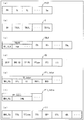
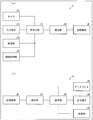
符号化データ#1におけるピクチャレイヤ以下の階層の構造を図2に示す。図2の(a)は、ピクチャPICTを規定するピクチャレイヤの構造を示す図である。図2の(b)は、スライスSを規定するスライスレイヤの構造を示す図である。図2の(c)は、ツリーブロック(Tree block)TBLKを規定するツリーブロックレイヤの構造を示す図である。図2の(d)は、ツリーブロックTBLKに含まれる符号化単位(CU:Coding Unit)を規定するCUレイヤの構造を示す図である。
FIG. 2 shows the hierarchical structure below the picture layer in the encoded data # 1. FIG. 2A is a diagram illustrating a structure of a picture layer that defines a picture PICT. FIG. 2B is a diagram showing the structure of the slice layer that defines the slice S. FIG. 2C is a diagram illustrating a structure of a tree block layer that defines a tree block TBLK. (D) of FIG. 2 is a figure which shows the structure of the CU layer which prescribes | regulates the encoding unit (CU: Coding | Unit) contained in the tree block TBLK.
また、図2の(e)は、予測ツリー(PT:prediction tree)についての情報であり、インター予測(画面間予測)パーティションについての予測情報PTIであるインター予測情報PTI_Interの構造を示す図である。図2の(f)は、予測ツリーPTについての情報であり、イントラ予測(画面内予測)パーティションについての予測情報PTIであるイントラ予測情報PTI_Intraの構造を示す図である。図2の(g)は、符号化単位CUに含まれる変換ツリー(TT:transform tree)についての情報である変換単位情報TTIの構造を示す図である。
Further, (e) of FIG. 2 is a diagram illustrating the structure of inter prediction information PTI_Inter that is information about a prediction tree (PT: prediction tree) and is prediction information PTI about an inter prediction (inter-screen prediction) partition. . (F) of FIG. 2 is a figure which shows the structure of intra prediction information PTI_Intra which is the information about the prediction tree PT, and is the prediction information PTI about the intra prediction (intra-screen prediction) partition. (G) of FIG. 2 is a figure which shows the structure of the transformation unit information TTI which is the information about the transformation tree (TT: transform | tree) contained in the encoding unit CU.
また、図3、4は、ピクチャPICTからスライスS、ツリーブロックTBLK、予測単位PU、変換単位TUが分割される状態を示す図である。
3 and 4 are diagrams showing a state in which the slice S, the tree block TBLK, the prediction unit PU, and the transform unit TU are divided from the picture PICT.
(ピクチャレイヤ)
ピクチャレイヤでは、処理対象のピクチャPICT(以下、対象ピクチャとも称する)を復号するために動画像復号装置1が参照するデータの集合が規定されている。ピクチャPICTは、図2の(a)に示すように、ピクチャヘッダPH、および、スライスS1~SNSを含んでいる(NSはピクチャPICTに含まれるスライスの総数)。 (Picture layer)
In the picture layer, a set of data referred to by thevideo decoding device 1 for decoding a picture PICT to be processed (hereinafter also referred to as a target picture) is defined. As shown in FIG. 2A, the picture PICT includes a picture header PH and slices S 1 to S NS (NS is the total number of slices included in the picture PICT).
ピクチャレイヤでは、処理対象のピクチャPICT(以下、対象ピクチャとも称する)を復号するために動画像復号装置1が参照するデータの集合が規定されている。ピクチャPICTは、図2の(a)に示すように、ピクチャヘッダPH、および、スライスS1~SNSを含んでいる(NSはピクチャPICTに含まれるスライスの総数)。 (Picture layer)
In the picture layer, a set of data referred to by the
なお、以下、スライスS1~SNSのそれぞれを区別する必要が無い場合、符号の添え字を省略して記述することがある。また、以下に説明する符号化データ#1に含まれるデータであって、添え字を付している他のデータについても同様である。
In the following description, when it is not necessary to distinguish each of the slices S 1 to S NS , the reference numerals may be omitted. The same applies to other data with subscripts included in encoded data # 1 described below.
ピクチャヘッダPHには、対象ピクチャの復号方法を決定するために動画像復号装置1が参照する符号化パラメータ群が含まれている。例えば、動画像符号化装置2が符号化の際に用いた可変長符号化のモードを示す符号化モード情報(entropy_coding_mode_flag)は、ピクチャヘッダPHに含まれる符号化パラメータの一例である。
The picture header PH includes a coding parameter group referred to by the video decoding device 1 in order to determine a decoding method of the target picture. For example, the encoding mode information (entropy_coding_mode_flag) indicating the variable length encoding mode used in encoding by the moving image encoding device 2 is an example of an encoding parameter included in the picture header PH.
entropy_coding_mode_flagが0の場合、当該ピクチャPICTは、LCEC(Low Complexity Entropy Coding)、またはCAVLC(Context-based Adaptive Variable Length Coding)によって符号化されている。また、entropy_coding_mode_flagが1である場合、当該ピクチャPICTは、CABAC(Context-based Adaptive Binary Arithmetic Coding)によって符号化されている。
When entropy_coding_mode_flag is 0, the picture PICT is encoded by LCEC (Low Complexity Entropy Coding) or CAVLC (Context-based Adaptive Variable Length Coding). When entropy_coding_mode_flag is 1, the picture PICT is encoded by CABAC (Context-based Adaptive Binary Arithmetic Coding).
なお、ピクチャヘッダPHは、ピクチャー・パラメーター・セット(PPS:Picture Parameter Set)とも称される。
Note that the picture header PH is also referred to as a picture parameter set (PPS).
(スライスレイヤ)
スライスレイヤでは、処理対象のスライスS(対象スライスとも称する)を復号するために動画像復号装置1が参照するデータの集合が規定されている。スライスSは、図2の(b)に示すように、スライスヘッダSH、および、ツリーブロックTBLK1~TBLKNC(NCはスライスSに含まれるツリーブロックの総数)のシーケンスを含んでいる。 (Slice layer)
In the slice layer, a set of data referred to by thevideo decoding device 1 for decoding the slice S to be processed (also referred to as a target slice) is defined. As shown in FIG. 2B, the slice S includes a slice header SH and a sequence of tree blocks TBLK 1 to TBLK NC (where NC is the total number of tree blocks included in the slice S).
スライスレイヤでは、処理対象のスライスS(対象スライスとも称する)を復号するために動画像復号装置1が参照するデータの集合が規定されている。スライスSは、図2の(b)に示すように、スライスヘッダSH、および、ツリーブロックTBLK1~TBLKNC(NCはスライスSに含まれるツリーブロックの総数)のシーケンスを含んでいる。 (Slice layer)
In the slice layer, a set of data referred to by the
スライスヘッダSHには、対象スライスの復号方法を決定するために動画像復号装置1が参照する符号化パラメータ群が含まれる。スライスタイプを指定するスライスタイプ指定情報(slice_type)は、スライスヘッダSHに含まれる符号化パラメータの一例である。
The slice header SH includes a coding parameter group that the moving image decoding apparatus 1 refers to in order to determine a decoding method of the target slice. Slice type designation information (slice_type) for designating a slice type is an example of an encoding parameter included in the slice header SH.
スライスタイプ指定情報により指定可能なスライスタイプとしては、(1)符号化の際にイントラ予測のみを用いるIスライス、(2)符号化の際に単方向予測、または、イントラ予測を用いるPスライス、(3)符号化の際に単方向予測、双方向予測、または、イントラ予測を用いるBスライスなどが挙げられる。
As slice types that can be specified by the slice type specification information, (1) I slice using only intra prediction at the time of encoding, (2) P slice using unidirectional prediction or intra prediction at the time of encoding, (3) B-slice using unidirectional prediction, bidirectional prediction, or intra prediction at the time of encoding may be used.
また、スライスヘッダSHには、動画像復号装置1の備えるループフィルタ(不図示)によって参照されるフィルタパラメータが含まれていてもよい。
Further, the slice header SH may include a filter parameter referred to by a loop filter (not shown) included in the video decoding device 1.
また、図3の(a)に示すように、スライスSは、ピクチャPICTが分割されることによって形成されている。図3の(a)では、ピクチャPICT301が分割されて、スライスS302が形成されている。
Further, as shown in FIG. 3A, the slice S is formed by dividing the picture PICT. In FIG. 3A, the picture PICT301 is divided to form a slice S302.
(ツリーブロックレイヤ)
ツリーブロックレイヤでは、処理対象のツリーブロックTBLK(以下、対象ツリーブロックとも称する)を復号するために動画像復号装置1が参照するデータの集合が規定されている。 (Tree block layer)
In the tree block layer, a set of data referred to by thevideo decoding device 1 for decoding a processing target tree block TBLK (hereinafter also referred to as a target tree block) is defined.
ツリーブロックレイヤでは、処理対象のツリーブロックTBLK(以下、対象ツリーブロックとも称する)を復号するために動画像復号装置1が参照するデータの集合が規定されている。 (Tree block layer)
In the tree block layer, a set of data referred to by the
ツリーブロックTBLKは、ツリーブロックヘッダTBLKHと、符号化単位情報CU1~CUNL(NLはツリーブロックTBLKに含まれる符号化単位情報の総数)とを含む。ここで、まず、ツリーブロックTBLKと、符号化単位情報CUとの関係について説明すると次のとおりである。
The tree block TBLK includes a tree block header TBLKH and coding unit information CU 1 to CU NL (NL is the total number of coding unit information included in the tree block TBLK). Here, first, a relationship between the tree block TBLK and the coding unit information CU will be described as follows.
ツリーブロックTBLKは、イントラ予測またはインター予測、および、変換の各処理のためのブロックサイズを特定するためのユニットに分割される。
The tree block TBLK is divided into units for specifying a block size for each process of intra prediction or inter prediction and conversion.
ツリーブロックTBLKの上記ユニットは、再帰的な4分木分割により分割されている。この再帰的な4分木分割により得られる木構造のことを以下、符号化ツリー(coding tree)と称する。
The above unit of the tree block TBLK is divided by recursive quadtree partitioning. The tree structure obtained by this recursive quadtree partitioning is hereinafter referred to as a coding tree.
以下、符号化ツリーの末端のノードであるリーフ(leaf)に対応するユニットを、符号化ノード(coding node)として参照する。また、符号化ノードは、符号化処理の基本的な単位となるため、以下、符号化ノードのことを、符号化単位(CU)とも称する。
Hereinafter, a unit corresponding to a leaf that is a node at the end of the coding tree is referred to as a coding node. In addition, since the encoding node is a basic unit of the encoding process, hereinafter, the encoding node is also referred to as an encoding unit (CU).
つまり、符号化単位情報(以下、CU情報と称する)CU1~CUNLは、ツリーブロックTBLKを再帰的に4分木分割して得られる各符号化ノード(符号化単位)に対応する情報である。
That is, coding unit information (hereinafter referred to as CU information) CU 1 to CU NL is information corresponding to each coding node (coding unit) obtained by recursively dividing the tree block TBLK into quadtrees. is there.
また、符号化ツリーのルート(root)は、ツリーブロックTBLKに対応付けられる。換言すれば、ツリーブロックTBLKは、複数の符号化ノードを再帰的に含む4分木分割の木構造の最上位ノードに対応付けられる。
Also, the root of the coding tree is associated with the tree block TBLK. In other words, the tree block TBLK is associated with the highest node of the tree structure of the quadtree partition that recursively includes a plurality of encoding nodes.
なお、各符号化ノードのサイズは、当該符号化ノードが直接に属する符号化ノード(すなわち、当該符号化ノードの1階層上位のノードのユニット)のサイズの縦横とも半分である。
Note that the size of each coding node is half the size of the coding node to which the coding node directly belongs (that is, the unit of the node one layer higher than the coding node).
また、各符号化ノードのとり得るサイズは、符号化データ#1のシーケンスパラメータセットSPSに含まれる、符号化ノードのサイズ指定情報および最大階層深度(maximum hierarchical depth)に依存する。例えば、ツリーブロックTBLKのサイズが64×64画素であって、最大階層深度が3である場合には、当該ツリーブロックTBLK以下の階層における符号化ノードは、4種類のサイズ、すなわち、64×64画素、32×32画素、16×16画素、および8×8画素の何れかをとり得る。
Also, the size that each coding node can take depends on the size designation information of the coding node and the maximum hierarchy depth (maximum hierarchical depth) included in the sequence parameter set SPS of the coded data # 1. For example, when the size of the tree block TBLK is 64 × 64 pixels and the maximum hierarchical depth is 3, the encoding nodes in the hierarchy below the tree block TBLK have four sizes, that is, 64 × 64. Any of pixel, 32 × 32 pixel, 16 × 16 pixel, and 8 × 8 pixel can be taken.
また、ブロック構造としては、図3の(a)に示すように、スライスSが分割されて、ツリーブロックTBLK303が形成されている。そして、図3の(b)に示すように、ツリーブロックTBLK303が分割されてCU311が形成されている。
As the block structure, as shown in FIG. 3A, the slice S is divided to form a tree block TBLK303. As shown in FIG. 3B, the tree block TBLK303 is divided to form a CU311.
また、図3の(c)に、最大階層深度が「2」の場合に、ツリーブロックTBLK303が四分木分割される様子を示す。図3の(c)に示すように、最大階層深度が「2」で、後述するCU分割フラグ(split_coding_unit_flag)の値が階層0で「1」であり、かつ階層1でも「1」の場合、CU311bが符号化ノードとなる。なお、最大階層深度が「1」で、CU分割フラグの値が階層0で「1」の場合、CU311aが符号化ノードとなる。
FIG. 3C shows a state where the tree block TBLK 303 is divided into quadtrees when the maximum hierarchy depth is “2”. As shown in FIG. 3C, when the maximum layer depth is “2”, the value of a CU partition flag (split_coding_unit_flag) described later is “1” in layer 0, and “1” in layer 1 as well, The CU 311b is an encoding node. When the maximum layer depth is “1” and the value of the CU partition flag is “1” in layer 0, the CU 311a is an encoding node.
(ツリーブロックヘッダ)
ツリーブロックヘッダTBLKHには、対象ツリーブロックの復号方法を決定するために動画像復号装置1が参照する符号化パラメータが含まれる。具体的には、図2の(c)に示すように、対象ツリーブロックの各CUへの分割パターンを指定するツリーブロック分割情報SP_TBLK、および、量子化ステップの大きさを指定する量子化パラメータ差分Δqp(qp_delta)が含まれる。 (Tree block header)
The tree block header TBLKH includes an encoding parameter referred to by thevideo decoding device 1 in order to determine a decoding method of the target tree block. Specifically, as shown in FIG. 2C, tree block division information SP_TBLK that designates a division pattern of the target tree block into each CU, and a quantization parameter difference that designates the size of the quantization step. Δqp (qp_delta) is included.
ツリーブロックヘッダTBLKHには、対象ツリーブロックの復号方法を決定するために動画像復号装置1が参照する符号化パラメータが含まれる。具体的には、図2の(c)に示すように、対象ツリーブロックの各CUへの分割パターンを指定するツリーブロック分割情報SP_TBLK、および、量子化ステップの大きさを指定する量子化パラメータ差分Δqp(qp_delta)が含まれる。 (Tree block header)
The tree block header TBLKH includes an encoding parameter referred to by the
ツリーブロック分割情報SP_TBLKは、ツリーブロックを分割するための符号化ツリーを表す情報であり、具体的には、対象ツリーブロックに含まれる各CUの形状、サイズ、および、対象ツリーブロック内での位置を指定する情報である。
The tree block division information SP_TBLK is information representing a coding tree for dividing the tree block. Specifically, the shape and size of each CU included in the target tree block, and the position in the target tree block Is information to specify.
なお、ツリーブロック分割情報SP_TBLKは、CUの形状やサイズを明示的に含んでいなくてもよい。例えばツリーブロック分割情報SP_TBLKは、対象ツリーブロック全体またはツリーブロックの部分領域を四分割するか否かを示すフラグ(split_coding_unit_flag)の集合であってもよい。その場合、ツリーブロックの形状やサイズを併用することで各CUの形状やサイズを特定できる。
Note that the tree block division information SP_TBLK may not explicitly include the shape or size of the CU. For example, the tree block division information SP_TBLK may be a set of flags (split_coding_unit_flag) indicating whether or not the entire target tree block or a partial area of the tree block is divided into four. In that case, the shape and size of each CU can be specified by using the shape and size of the tree block together.
また、量子化パラメータ差分Δqpは、対象ツリーブロックにおける量子化パラメータqpと、当該対象ツリーブロックの直前に符号化されたツリーブロックにおける量子化パラメータqp’との差分qp-qp’である。
Further, the quantization parameter difference Δqp is a difference qp−qp ′ between the quantization parameter qp in the target tree block and the quantization parameter qp ′ in the tree block encoded immediately before the target tree block.
(CUレイヤ)
CUレイヤでは、処理対象のCU(以下、対象CUとも称する)を復号するために動画像復号装置1が参照するデータの集合が規定されている。 (CU layer)
In the CU layer, a set of data referred to by thevideo decoding device 1 for decoding a CU to be processed (hereinafter also referred to as a target CU) is defined.
CUレイヤでは、処理対象のCU(以下、対象CUとも称する)を復号するために動画像復号装置1が参照するデータの集合が規定されている。 (CU layer)
In the CU layer, a set of data referred to by the
ここで、CU情報CUに含まれるデータの具体的な内容の説明をする前に、CUに含まれるデータの木構造について説明する。符号化ノードは、予測ツリーPTおよび変換ツリーTTのルートとなる。予測ツリーおよび変換ツリーについて説明すると次のとおりである。
Here, before explaining the specific contents of the data included in the CU information CU, the tree structure of the data included in the CU will be described. The encoding node is the root of the prediction tree PT and the transformation tree TT. The prediction tree and the conversion tree are described as follows.
予測ツリーにおいては、符号化ノードが1または複数の予測ブロックに分割され、各予測ブロックの位置とサイズとが規定される。別の表現でいえば、予測ブロックは、符号化ノードを構成する1または複数の重複しない領域である。また、予測ツリーは、上述の分割により得られた1または複数の予測ブロックを含む。
In the prediction tree, the encoding node is divided into one or a plurality of prediction blocks, and the position and size of each prediction block are defined. In other words, the prediction block is one or a plurality of non-overlapping areas constituting the encoding node. The prediction tree includes one or a plurality of prediction blocks obtained by the above division.
予測処理は、この予測ブロックごとに行われる。以下、予測の単位である予測ブロックのことを、予測単位(PU:prediction unit)とも称する。
Prediction processing is performed for each prediction block. Hereinafter, a prediction block that is a unit of prediction is also referred to as a prediction unit (PU).
また、変換ツリーにおいては、符号化ノードが1または複数の変換ブロックに分割され、各変換ブロックの位置とサイズとが規定される。別の表現でいえば、変換ブロックは、符号化ノードを構成する1または複数の重複しない領域のことである。また、変換ツリーは、上述の分割より得られた1または複数の変換ブロックを含む。
Also, in the transform tree, the encoding node is divided into one or a plurality of transform blocks, and the position and size of each transform block are defined. In other words, the transform block is one or a plurality of non-overlapping areas constituting the encoding node. The conversion tree includes one or a plurality of conversion blocks obtained by the above division.
変換処理は、この変換ブロックごとに行われる。以下、変換の単位である変換ブロックのことを、変換単位(TU:transform unit)とも称する。
Conversion processing is performed for each conversion block. Hereinafter, a transform block that is a unit of transform is also referred to as a transform unit (TU).
(CU情報CUのデータ構造)
続いて、図2の(d)を参照しながらCU情報CUに含まれるデータの具体的な内容について説明する。図2の(d)に示すように、CU情報CUは、スキップフラグSKIP、マージフラグMRG_CU、対象CUの各予測単位への分割パターンを指定するPU分割情報SP_PU、予測タイプ情報PType、PT情報PTI、および、TT情報TTIを含んでいる。 (Data structure of CU information CU)
Next, specific contents of data included in the CU information CU will be described with reference to FIG. As shown in FIG. 2D, the CU information CU includes a skip flag SKIP, a merge flag MRG_CU, PU partition information SP_PU that specifies a partition pattern for each prediction unit of the target CU, prediction type information PType, PT information PTI. And TT information TTI.
スキップフラグSKIPは、対象のCUについて、スキップモードが適用されているか否かを示すフラグであり、スキップフラグSKIPの値が1の場合、すなわち、対象CUにスキップモードが適用されている場合、スキップの対象となる各種情報は省略され、復号される際には、既定値または推定値が用いられる。なお、対象となる各種情報については、後述する。また、スキップフラグSKIPは、Iスライスでは省略される。
The skip flag SKIP is a flag indicating whether or not the skip mode is applied to the target CU. When the value of the skip flag SKIP is 1, that is, when the skip mode is applied to the target CU, skip is performed. Various types of information to be subjected to are omitted, and a default value or an estimated value is used when decoding. Various types of information to be processed will be described later. The skip flag SKIP is omitted for the I slice.
マージフラグMRG_CUは、対象のCUについて、マージモードが適用されているか否かを示すフラグであり、マージフラグMRG_CUの値が1の場合、すなわち、対象CUにマージモードが適用されている場合、マージの対象となる各種情報は省略され、復号される際には、推定値が用いられる。なお、対象となる各種情報については、後述する。
The merge flag MRG_CU is a flag indicating whether or not the merge mode is applied to the target CU. When the value of the merge flag MRG_CU is 1, that is, when the merge mode is applied to the target CU, the merge flag MRG_CU is merged. Various pieces of information to be subjected to are omitted, and estimated values are used when decoding. Various types of information to be processed will be described later.
PU分割情報SP_PUは、対象CUに含まれる各PUの形状、サイズ、および、対象CU内での位置を決定するための情報である。例えば、PU分割情報SP_PUは、対象CUから、イントラ分割を指定するイントラ分割フラグ(intra_split_flag)、および、対象CUから、インター分割を指定するインター分割フラグ(inter_partitining_idc)の少なくとも何れか一方から実現することができる。
The PU partition information SP_PU is information for determining the shape and size of each PU included in the target CU and the position in the target CU. For example, the PU partition information SP_PU is realized from at least one of an intra partition flag (intra_split_flag) that specifies intra partition from the target CU and an inter partition flag (inter_partitining_idc) that specifies inter partition from the target CU. Can do.
イントラ分割フラグは、対象CUに含まれる各イントラPU(イントラ予測が用いられるPU)の形状、サイズ、および、対象CU内での位置を指定する情報である。
The intra division flag is information that specifies the shape, size, and position in the target CU of each intra PU included in the target CU (PU in which intra prediction is used).
インター分割フラグは、対象CUに含まれる各インターPU(インター予測が用いられるPU)の形状、サイズ、および、対象CU内での位置を指定する情報である。
The inter division flag is information for designating the shape and size of each inter PU included in the target CU (PU in which inter prediction is used), and the position in the target CU.
予測タイプ情報PTypeは、対象PUについての予測画像生成方法として、イントラ予測を用いるのか、または、インター予測を用いるのかを指定する情報である。
Prediction type information PType is information that specifies whether intra prediction or inter prediction is used as a prediction image generation method for the target PU.
PT情報PTIは、対象CUに含まれるPTに関する情報である。言い換えれば、PT情報PTIは、PTに含まれる1または複数のPUそれぞれに関する情報の集合であり、動画像復号装置1により予測画像を生成する際に参照される。PT情報PTIは、図2の(e)、(f)に示すように、予測タイプ情報PTypeが何れの予測方法を指定するのかに応じて、インター予測情報(PTI_Inter)、または、イントラ予測情報(PTI_Intra)より構成される。以下では、イントラ予測が適用されるPUをイントラPUとも呼称し、インター予測が適用されるPUをインターPUとも呼称する。
PT information PTI is information related to the PT included in the target CU. In other words, the PT information PTI is a set of information related to each of one or more PUs included in the PT, and is referred to when the moving image decoding apparatus 1 generates a predicted image. As shown in (e) and (f) of FIG. 2, the PT information PTI includes inter prediction information (PTI_Inter) or intra prediction information (in accordance with which prediction method the prediction type information PType specifies). PTI_Intra). Hereinafter, a PU to which intra prediction is applied is also referred to as an intra PU, and a PU to which inter prediction is applied is also referred to as an inter PU.
TT情報TTIは、対象CUに含まれるTTに関する情報である。言い換えれば、TT情報TTIは、TTに含まれる1または複数のTUそれぞれに関する情報の集合であり、動画像復号装置1により残差データを復号する際に参照される。
TT information TTI is information related to TT included in the target CU. In other words, the TT information TTI is a set of information regarding each of one or a plurality of TUs included in the TT, and is referred to when the moving image decoding apparatus 1 decodes residual data.
(インター予測情報PTI_Inter)
インター予測情報PTI_Interは、動画像復号装置1が、インター予測によってインター予測画像を生成する際に参照される符号化パラメータが含まれる。図2の(e)に示すように、インター予測情報PTI_Interには、各PUについてのインター予測パラメータPP_Inter1~PP_InterNe(Neは、対象CUに含まれるインター予測PUの総数)が含まれている。 (Inter prediction information PTI_Inter)
The inter prediction information PTI_Inter includes a coding parameter that is referred to when thevideo decoding device 1 generates an inter prediction image by inter prediction. As shown in (e) of FIG. 2, the inter prediction information PTI_Inter includes inter prediction parameters PP_Inter1 to PP_InterNe (Ne is the total number of inter prediction PUs included in the target CU) for each PU.
インター予測情報PTI_Interは、動画像復号装置1が、インター予測によってインター予測画像を生成する際に参照される符号化パラメータが含まれる。図2の(e)に示すように、インター予測情報PTI_Interには、各PUについてのインター予測パラメータPP_Inter1~PP_InterNe(Neは、対象CUに含まれるインター予測PUの総数)が含まれている。 (Inter prediction information PTI_Inter)
The inter prediction information PTI_Inter includes a coding parameter that is referred to when the
インターPUは、対象CUを、2N×2N画素(対象CUと同一サイズ)、2N×N画素、N×2N画素、およびN×N画素の4つの対称的分割(symmetric splittings)により分割することで作成される。
The inter PU divides the target CU by four symmetrical divisions of 2N × 2N pixels (the same size as the target CU), 2N × N pixels, N × 2N pixels, and N × N pixels. Created.
具体的に、図4の(b)を用いて説明する。図4の(b)に示すように、CU311から、2N×2N画素に分割されるとPU412aとなり、2N×N画素に分割されるとPU412bおよびPU412cとなり、N×2N画素に分割されるとPU412dおよびPU412eとなり、N×N画素に分割されるとPU412f~PU412iとなる。
Specifically, this will be described with reference to FIG. As shown in FIG. 4 (b), when it is divided from the CU 311 into 2N × 2N pixels, it becomes PU412a, when it is divided into 2N × N pixels, it becomes PU412b and PU412c, and when it is divided into N × 2N pixels, it is PU412d. And PU412e, and when divided into N × N pixels, PU412f to PU412i.
(インター予測パラメータ)
図2の(e)に示すように、インター予測パラメータPP_Interは、マージフラグMRG_PU、インター予測タイプIPT、参照画像インデックスRI、推定動きベクトルインデックスPMVI、動きベクトル残差MVDを含んでいる。 (Inter prediction parameter)
As shown in FIG. 2E, the inter prediction parameter PP_Inter includes a merge flag MRG_PU, an inter prediction type IPT, a reference image index RI, an estimated motion vector index PMVI, and a motion vector residual MVD.
(イントラ予測情報PTI_Intra)
イントラ予測情報PTI_Intraは、動画像復号装置1が、イントラ予測によってイントラ予測画像を生成する際に参照される符号化パラメータが含まれる。図2の(f)に示すように、イントラ予測情報PTI_Intraには、各PUについてのイントラ予測パラメータPP_Intra1~PP_IntraNa(Naは、対象CUに含まれるイントラ予測PUの総数)が含まれている。 (Intra prediction information PTI_Intra)
The intra prediction information PTI_Intra includes a coding parameter that is referred to when thevideo decoding device 1 generates an intra predicted image by intra prediction. As shown in FIG. 2 (f), the intra prediction information PTI_Intra includes intra prediction parameters PP_Intra1 to PP_IntraNa (Na is the total number of intra prediction PUs included in the target CU) for each PU.
イントラ予測情報PTI_Intraは、動画像復号装置1が、イントラ予測によってイントラ予測画像を生成する際に参照される符号化パラメータが含まれる。図2の(f)に示すように、イントラ予測情報PTI_Intraには、各PUについてのイントラ予測パラメータPP_Intra1~PP_IntraNa(Naは、対象CUに含まれるイントラ予測PUの総数)が含まれている。 (Intra prediction information PTI_Intra)
The intra prediction information PTI_Intra includes a coding parameter that is referred to when the
イントラPUは、イントラ分割フラグが1であれば、対象CUを4つのPUへと対称的に分割することにより生成され、イントラ分割フラグが0であれば、対象CUを分割することなく、対象CU自身がPUとして取り扱われる。したがって、対象CUのサイズを2N×2N画素とすると、イントラPUは、2N×2N画素(分割なし)、および、N×N画素(4分割)の何れかのサイズを取り得る(ここで、N=2n、nは1以上の任意の整数)。例えば、対象CUが、128×128画素であれば、128×128画素、および、64×64画素のイントラPUへ分割することが可能である。
The intra PU is generated by symmetrically dividing the target CU into four PUs if the intra split flag is 1, and if the intra split flag is 0, the target CU is not split without dividing the target CU. It is treated as a PU. Therefore, when the size of the target CU is 2N × 2N pixels, the intra PU can take any size of 2N × 2N pixels (no division) and N × N pixels (four divisions) (where N = 2 n , n is an arbitrary integer of 1 or more). For example, if the target CU is 128 × 128 pixels, it can be divided into 128 × 128 pixel and 64 × 64 pixel intra PUs.
具体的に、図4の(a)を用いて説明する。図4の(a)に示すように、CU311から、2N×2N画素に分割されるとPU411aとなり、N×N画素に分割されるとPU412b~PU412eとなる。
Specifically, this will be described with reference to FIG. As shown in FIG. 4A, when the CU 311 is divided into 2N × 2N pixels, it becomes PU 411a, and when it is divided into N × N pixels, it becomes PU 412b to PU 412e.
(イントラ予測パラメータPP_Intra)
図2の(f)に示すように、イントラ予測パラメータPP_Intraは、マージフラグMRG_PU、イントラ予測モードIPMを含んでいる。 (Intra prediction parameter PP_Intra)
As shown in (f) of FIG. 2, the intra prediction parameter PP_Intra includes a merge flag MRG_PU and an intra prediction mode IPM.
図2の(f)に示すように、イントラ予測パラメータPP_Intraは、マージフラグMRG_PU、イントラ予測モードIPMを含んでいる。 (Intra prediction parameter PP_Intra)
As shown in (f) of FIG. 2, the intra prediction parameter PP_Intra includes a merge flag MRG_PU and an intra prediction mode IPM.
(TT情報TTI)
図2の(g)に示すように、TT情報TTIは、マージフラグMRG_TU、変換サイズTTS、変換タイプTTType、変換係数TTC、空間領域の変換係数の存在の有無CBP、周波数領域の変換係数の存在の有無CTC、量子化予測残差QDを、対象CUに含まれるTUの総数分含んでいる。 (TT information TTI)
As shown in FIG. 2G, TT information TTI includes merge flag MRG_TU, transform size TTS, transform type TTType, transform coefficient TTC, presence / absence of spatial domain transform coefficient CBP, and presence of frequency domain transform coefficient. Presence / absence CTC and quantization prediction residual QD are included for the total number of TUs included in the target CU.
ここで、周波数領域の変換係数の存在の有無CTCとは、対象周波数領域(対象変換単位)に含まれる各変換係数が0であるか否かを示す情報や、対象周波数領域を分割して得られる各部分単位に非ゼロ変換係数が含まれるか否かを示す情報(非ゼロ変換係数存否情報)を含む概念である。
Here, presence / absence CTC of presence / absence of a transform coefficient in the frequency domain is obtained by dividing the target frequency domain by information indicating whether each transform coefficient included in the target frequency domain (target transform unit) is 0 or not. This is a concept including information (non-zero conversion coefficient existence information) indicating whether or not each partial unit includes a non-zero conversion coefficient.
なお、対象周波数領域に含まれる各変換係数が0であるか否かを示す情報は、significant_coeff_flag[xC][yC](ここで、[xC][yC]は、対象周波数領域における各変換係数を位置を示す)と呼ばれることもあり、対象周波数領域を分割して得られる各部分単位に非ゼロ変換係数が含まれるか否かを示す情報は、significant_coeff_group_flag[xCG][yCG](ここで、[xCG][yCG]は、対象周波数領域における各部分単位の位置を示す)と呼ばれることもある。
Note that information indicating whether or not each transform coefficient included in the target frequency domain is 0 is significant_coeff_flag [xC] [yC] (where [xC] [yC] represents each transform coefficient in the target frequency domain. Information indicating whether or not each partial unit obtained by dividing the target frequency region includes a non-zero transform coefficient is significant_coeff_group_flag [xCG] [yCG] (where [ xCG] [yCG] may be referred to as the position of each partial unit in the target frequency domain.
TUは、対象CUを階層的に四分木分割することにより形成されており、対象CUまたは対象CUの部分領域の分割を行うのか否かを示す情報(split_transform_flag)により、サイズが決定する。split_transform_flagは基本的には四分木の各ノードに対して符号化されるが、変換サイズに関する制約(最大変換サイズ、最小変換サイズ、四分木の最大階層深度)に応じて省略されて推定される場合もある。
The TU is formed by hierarchically dividing the target CU into a quadtree, and the size is determined by information (split_transform_flag) indicating whether or not the target CU or a partial region of the target CU is to be divided. split_transform_flag is basically encoded for each node of the quadtree, but is omitted and estimated according to the constraints on the transform size (maximum transform size, minimum transform size, maximum hierarchy depth of the quadtree). There is also a case.
図4の(c)に、CU311が四分木分割されて、TUが形成される様子を示す。図4の(c)に示すように、階層0および階層1において、ノードの分割を行うことが示されている場合、PU413bがTUとなる。また、階層0でノードの分割を行い、階層1でノードの分割を行わないことが示されている場合、PU413aがTUとなる。
FIG. 4 (c) shows a state where CU 311 is divided into quadtrees to form TUs. As shown in FIG. 4C, when it is indicated that node division is performed in the hierarchy 0 and the hierarchy 1, the PU 413b is a TU. In addition, when it is indicated that the node is divided at the hierarchy 0 and the node is not divided at the hierarchy 1, the PU 413a is a TU.
例えば、最大階層深度が「2」であり、対象CUのサイズが、64×64の場合、対象CUに含まれるTUは、64×64画素、32×32画素、または16×16画素のサイズをとり得る。
For example, when the maximum hierarchical depth is “2” and the size of the target CU is 64 × 64, the TU included in the target CU has a size of 64 × 64 pixels, 32 × 32 pixels, or 16 × 16 pixels. It can take.
量子化予測残差QDは、動画像符号化装置2が以下の処理1~3を、処理対象のブロックである対象ブロックに施すことによって生成した符号化データである。
The quantized prediction residual QD is encoded data generated by the moving image encoding apparatus 2 performing the following processes 1 to 3 on a target block that is a processing target block.
処理1:符号化対象画像から予測画像を減算した予測残差をDCT変換(Discrete Cosine Transform)する;
処理2:処理1にて得られた変換係数を量子化する;
処理3:処理2にて量子化された変換係数を可変長符号化する;
なお、上述した量子化パラメータqpは、動画像符号化装置2が変換係数を量子化する際に用いた量子化ステップQPの大きさを表す(QP=2qp/6)。 Process 1: DCT transform (Discrete Cosine Transform) of the prediction residual obtained by subtracting the prediction image from the encoding target image;
Process 2: Quantize the transform coefficient obtained inProcess 1;
Process 3: Variable length coding is performed on the transform coefficient quantized inProcess 2;
The quantization parameter qp described above represents the magnitude of the quantization step QP used when the movingimage coding apparatus 2 quantizes the transform coefficient (QP = 2 qp / 6 ).
処理2:処理1にて得られた変換係数を量子化する;
処理3:処理2にて量子化された変換係数を可変長符号化する;
なお、上述した量子化パラメータqpは、動画像符号化装置2が変換係数を量子化する際に用いた量子化ステップQPの大きさを表す(QP=2qp/6)。 Process 1: DCT transform (Discrete Cosine Transform) of the prediction residual obtained by subtracting the prediction image from the encoding target image;
Process 2: Quantize the transform coefficient obtained in
Process 3: Variable length coding is performed on the transform coefficient quantized in
The quantization parameter qp described above represents the magnitude of the quantization step QP used when the moving
(動画像復号装置1)
次に、図1、5~12を参照して、動画像復号装置1の構成について説明する。図1は、動画像復号装置1の要部構成を示すブロック図である。図1に示すように、動画像復号装置1は、TBLK復号部(復号手段)10、フレームメモリ21を含む構成であり、TBLK復号部10には、TBLK情報復号部11、CU情報復号部12、PT情報復号部13、TT情報復号部(復号手段)14、およびCU画像生成部15が含まれている。また、CU情報復号部12にはCU情報推定部31が含まれ、PT情報復号部13にはPT情報推定部32が含まれ、TT情報復号部14にはTT情報推定部(推定手段)33が含まれている。 (Moving picture decoding apparatus 1)
Next, the configuration of thevideo decoding device 1 will be described with reference to FIGS. FIG. 1 is a block diagram showing a main configuration of the moving picture decoding apparatus 1. As shown in FIG. 1, the moving picture decoding apparatus 1 includes a TBLK decoding unit (decoding unit) 10 and a frame memory 21. The TBLK decoding unit 10 includes a TBLK information decoding unit 11 and a CU information decoding unit 12. , A PT information decoding unit 13, a TT information decoding unit (decoding means) 14, and a CU image generation unit 15. The CU information decoding unit 12 includes a CU information estimation unit 31, the PT information decoding unit 13 includes a PT information estimation unit 32, and the TT information decoding unit 14 includes a TT information estimation unit (estimation unit) 33. It is included.
次に、図1、5~12を参照して、動画像復号装置1の構成について説明する。図1は、動画像復号装置1の要部構成を示すブロック図である。図1に示すように、動画像復号装置1は、TBLK復号部(復号手段)10、フレームメモリ21を含む構成であり、TBLK復号部10には、TBLK情報復号部11、CU情報復号部12、PT情報復号部13、TT情報復号部(復号手段)14、およびCU画像生成部15が含まれている。また、CU情報復号部12にはCU情報推定部31が含まれ、PT情報復号部13にはPT情報推定部32が含まれ、TT情報復号部14にはTT情報推定部(推定手段)33が含まれている。 (Moving picture decoding apparatus 1)
Next, the configuration of the
動画像復号装置1は、概略的に言えば、符号化データ#1を復号することによって復号画像#2を生成し、出力する装置である。また、動画像復号装置1は、その一部に、H.264/MPEG-4 AVC規格に採用されている技術、VCEG(Video Coding Expert Group)における共同開発用コーデックであるKTAソフトウェアに採用されている技術、TMuC(Test Model under Consideration)ソフトウェアに採用されている技術、およびその後継コーデックであるWorking Draft 1 of High-Efficiency Video Coding(HEVC WD1)に採用されている方式を用いている動画像復号装置である。
Schematically speaking, the moving picture decoding apparatus 1 is an apparatus that generates and outputs a decoded image # 2 by decoding the encoded data # 1. In addition, the moving image decoding apparatus 1 includes, as part thereof, H.264. H.264 / MPEG-4 AVC standard technology, VCEG (Video Coding Expert Group) technology used in KTA software, which is a joint development codec, TMuC (Test Model Underside) software This is a video decoding apparatus using the technology and the method adopted in WorkingWorkDraft 1 of High-Efficiency Video Coding (HEVC WD1).
動画像復号装置1は、予測単位毎に予測画像を生成し、生成された予測画像と、符号化データ#1から復号された予測残差とを加算することによって復号画像#2を生成し、出力するものである。
The video decoding device 1 generates a prediction image for each prediction unit, generates a decoded image # 2 by adding the generated prediction image and a prediction residual decoded from the encoded data # 1, Output.
動画像復号装置1に入力された符号化データ#1は、TBLK復号部10のTBLK情報復号部11へ入力される。
The encoded data # 1 input to the video decoding device 1 is input to the TBLK information decoding unit 11 of the TBLK decoding unit 10.
(TBLK情報復号部11)
TBLK情報復号部11は、入力された符号化データ#1から、ツリーブロックヘッダTBLKHに含まれるツリーブロック分割情報SP_TBLK、および量子化パラメータ差分Δqp(TBLKH情報)を復号する。 (TBLK information decoding unit 11)
The TBLKinformation decoding unit 11 decodes the tree block division information SP_TBLK and the quantization parameter difference Δqp (TBLKH information) included in the tree block header TBLKH from the input encoded data # 1.
TBLK情報復号部11は、入力された符号化データ#1から、ツリーブロックヘッダTBLKHに含まれるツリーブロック分割情報SP_TBLK、および量子化パラメータ差分Δqp(TBLKH情報)を復号する。 (TBLK information decoding unit 11)
The TBLK
ツリーブロック分割情報には、対象ツリーブロックに含まれる各CUの形状、サイズ、および、対象ツリーブロック内での位置を指定する情報がふくまれている。そして、復号したTBLKH情報および符号化単位情報CUを含む分割情報#11をCU情報復号部12へ出力する。
The tree block division information includes information specifying the shape, size, and position within the target tree block of each CU included in the target tree block. Then, the division information # 11 including the decoded TBLKH information and the coding unit information CU is output to the CU information decoding unit 12.
(CU情報復号部12)
CU情報復号部12は、TBLK情報復号部11から入力された分割情報#11から、CU情報CUを復号して、CU復号情報#21、CU復号情報#22、CU復号情報#23を生成する。そして、CU復号情報#21をPT情報復号部13に、CU復号情報#22をTT情報復号部14に、CU復号情報#23をCU画像生成部15に入力する。 (CU information decoding unit 12)
The CUinformation decoding unit 12 decodes the CU information CU from the division information # 11 input from the TBLK information decoding unit 11, and generates CU decoding information # 21, CU decoding information # 22, and CU decoding information # 23. . Then, the CU decoding information # 21 is input to the PT information decoding unit 13, the CU decoding information # 22 is input to the TT information decoding unit 14, and the CU decoding information # 23 is input to the CU image generation unit 15.
CU情報復号部12は、TBLK情報復号部11から入力された分割情報#11から、CU情報CUを復号して、CU復号情報#21、CU復号情報#22、CU復号情報#23を生成する。そして、CU復号情報#21をPT情報復号部13に、CU復号情報#22をTT情報復号部14に、CU復号情報#23をCU画像生成部15に入力する。 (CU information decoding unit 12)
The CU
より具体的に説明すると、CU情報復号部12は、CU情報CUに含まれるスキップフラグSKIP(skip_flag)、およびマージフラグMRG_CU(cu_merge_flag)を復号する。そして、マージフラグMRG_CUの値が「1」の場合、さらに、CUマージ推定フラグ(cu_merge_left_flag)とCUマージレベルフラグ(cu_merge_level)とを復号する。
More specifically, the CU information decoding unit 12 decodes the skip flag SKIP (skip_flag) and the merge flag MRG_CU (cu_merge_flag) included in the CU information CU. When the value of the merge flag MRG_CU is “1”, the CU merge estimation flag (cu_merge_left_flag) and the CU merge level flag (cu_merge_level) are further decoded.
ここで、CUマージ推定フラグとは、値を推定するための参照先を示すフラグであり、CUマージレベルフラグとは、マージの対象となる情報を決定するためのフラグである。
Here, the CU merge estimation flag is a flag indicating a reference destination for estimating a value, and the CU merge level flag is a flag for determining information to be merged.
そして、CU情報復号部12のCU情報推定部31は、スキップフラグSKIP、マージフラグMRG_CU、CUマージ推定フラグ、CUマージレベルフラグに基づいて、PU分割情報SP_PUの値、および予測タイプ情報PTypeの値を復号または推定する。
Then, the CU information estimation unit 31 of the CU information decoding unit 12 determines the value of the PU partition information SP_PU and the value of the prediction type information PType based on the skip flag SKIP, the merge flag MRG_CU, the CU merge estimation flag, and the CU merge level flag. Is decoded or estimated.
より詳細には、CU情報推定部31は、CUマージ推定フラグ(cu_merge_left_flag)の値に応じて参照対象となるCU(参照CU)を決定する。そして、参照CUが、イントラ予測CUである場合(すなわち、PredModeがMODE_INTRA)、参照CUのイントラ分割フラグ(intra_split_flag)の値を、対象CUのイントラ分割フラグの値と推定する。
More specifically, the CU information estimation unit 31 determines a CU (reference CU) to be referred to according to the value of the CU merge estimation flag (cu_merge_left_flag). When the reference CU is an intra prediction CU (that is, PredMode is MODE_INTRA), the value of the intra split flag (intra_split_flag) of the reference CU is estimated as the value of the intra split flag of the target CU.
また、参照CUがインター予測CUである場合(すなわち、PredModeがMODE_INTER)、参照CU内のPUであり、かつ、対象CUと隣接する参照CUとの境界の辺に隣接するPUの中でサイズが最小のPUに最も近いサイズとなるように、対象CUのイントラ分割の値を設定する。
Further, when the reference CU is an inter prediction CU (that is, PredMode is MODE_INTER), the size of the PUs in the reference CU and adjacent to the side of the boundary between the target CU and the adjacent reference CU is the same. A value of the intra division of the target CU is set so that the size is closest to the smallest PU.
そして、CU情報復号部12は、復号したスキップフラグSKIPの値、マージフラグMRG_CUの値(および、マージフラグMRG_CUの値が「1」の場合は、復号したCUマージ推定フラグ、CUマージレベルフラグの値)、復号または推定したPU分割情報SP_PUの値、同じく復号または推定した予測タイプ情報PTypeの値を含むCU復号情報#21をPT情報復号部13に出力する。
Then, the CU information decoding unit 12 determines the value of the decoded skip flag SKIP, the value of the merge flag MRG_CU (and if the value of the merge flag MRG_CU is “1”, the decoded CU merge estimation flag, the CU merge level flag Value), the decoded or estimated PU partition information SP_PU value, and the decoded or estimated prediction type information PType value CU decoding information # 21 is output to the PT information decoding unit 13.
また、CU情報復号部12は、復号したスキップフラグSKIPの値、マージフラグMRG_CUの値(および、マージフラグMRG_CUの値が「1」の場合は、復号したCUマージ推定フラグ、CUマージレベルフラグの値)を含むCU復号情報#22をTT情報復号部14に出力する。
Also, the CU information decoding unit 12 determines the value of the decoded skip flag SKIP, the value of the merge flag MRG_CU (and, if the value of the merge flag MRG_CU is “1”, the decoded CU merge estimation flag, CU merge level flag CU decoding information # 22 including the value) is output to the TT information decoding unit 14.
また、CU情報復号部12は、復号または推定したPU分割情報SP_PUの値、および予測タイプ情報PTypeの値を含むCU復号情報#23をCU画像生成部15に出力する。
Also, the CU information decoding unit 12 outputs the CU decoding information # 23 including the value of the decoded or estimated PU partition information SP_PU and the value of the prediction type information PType to the CU image generation unit 15.
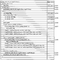
次に、CU情報復号部12における処理について、図5、6を参照して説明する。図5は、CU情報復号部12における処理の内容を示すシンタックステーブルである。また、図6は、CU情報復号部12においてマージの対象を説明するための図であり、図6の(a)は、マージフラグおよびCUマージレベルフラグと復号対象との関係を示す図であり、図6の(b)は、マージフラグおよびCUマージレベルフラグとマージ対象との関係を示す図である。
Next, processing in the CU information decoding unit 12 will be described with reference to FIGS. FIG. 5 is a syntax table showing the contents of processing in the CU information decoding unit 12. FIG. 6 is a diagram for explaining a merge target in the CU information decoding unit 12, and (a) in FIG. 6 is a diagram illustrating a relationship between a merge flag and a CU merge level flag and a decoding target. FIG. 6B is a diagram showing the relationship between the merge flag and the CU merge level flag and the object to be merged.
図5に示すように、CU情報復号部12は、まず、符号化単位情報CUに含まれるスキップフラグSKIP(skip_flag)を復号する(st501)。そして、スキップフラグSKIPの値が「1」であれば(st502)、予測単位PUにおける処理に入る(st503)。
As shown in FIG. 5, the CU information decoding unit 12 first decodes the skip flag SKIP (skip_flag) included in the coding unit information CU (st501). If the value of the skip flag SKIP is “1” (st502), the process in the prediction unit PU is started (st503).
一方、スキップフラグSKIPの値が「1」でなければ、マージフラグMRG_CU(cu_merge_flag)を復号する(st504)。そして、マージフラグMRG_CUの値が「1」であれば、さらにCUマージ推定フラグ(cu_merge_left_flag)、CUマージレベルフラグ(cu_merge_level)を復号する(st505)。
On the other hand, if the value of the skip flag SKIP is not “1”, the merge flag MRG_CU (cu_merge_flag) is decoded (st504). If the value of the merge flag MRG_CU is “1”, the CU merge estimation flag (cu_merge_left_flag) and the CU merge level flag (cu_merge_level) are further decoded (st505).
次に、CU情報推定部31は、予測タイプ情報PType(pred_mode)を復号または推定する(st506)。そして、復号または推定した予測タイプ情報PTypeが、イントラ予測を示すものである場合、イントラ分割フラグ(intra_split_flag)を復号または推定する(st507)。
Next, the CU information estimation unit 31 decodes or estimates the prediction type information PType (pred_mode) (st506). If the decoded or estimated prediction type information PType indicates intra prediction, the intra split flag (intra_split_flag) is decoded or estimated (st507).
一方、復号または推定した予測タイプ情報PTypeが、インター予測を示すものである場合、インター分割フラグ(inter_partitining_idc)を復号または推定する(st508)。
On the other hand, if the decoded or estimated prediction type information PType indicates inter prediction, the inter partition flag (inter_partitining_idc) is decoded or estimated (st508).
そして、予測単位PUにおける処理(prediction_unit、st509)、変換単位TUにおける処理(transform_tree、st510)に入る。
Then, the process in the prediction unit PU (prediction_unit, st509) and the process in the transform unit TU (transform_tree, st510) are entered.
次に、図6の(a)を参照して、復号および推定の対象となるフラグについて説明する。図6の(a)において、「○」は復号の対象となることを、「inf.」は推定値が用いられることを、「─」は不要であることをそれぞれ示している。
Next, with reference to (a) of FIG. 6, the flag used as the object of decoding and estimation is demonstrated. In FIG. 6A, “◯” indicates that it is a decoding target, “inf.” Indicates that an estimated value is used, and “-” indicates that it is not necessary.
図6の(a)に示すように、マージフラグMRG_CUの値が「0」の場合は、CU単位で復号または推定の対象となる全てのフラグが復号される。また、マージフラグMRG_CUの値が「1」で、マージレベルフラグの値が「0」の場合は、pred_mode、prediction_unit、transform_treeの3つが復号され、intra_split_flag、inter_partitining_idcの2つが推定される。
As shown in FIG. 6A, when the value of the merge flag MRG_CU is “0”, all flags to be decoded or estimated are decoded in units of CUs. When the value of the merge flag MRG_CU is “1” and the value of the merge level flag is “0”, three of pred_mode, prediction_unit, and transform_tree are decoded, and two of intra_split_flag and inter_partitining_idc are estimated.
また、マージフラグMRG_CUの値が「1」で、マージレベルフラグの値も「1」の場合は、prediction_unit、transform_treeの2つが復号され、pred_mode、intra_split_flag、inter_partitining_idcの3つが推定される。
Also, when the value of the merge flag MRG_CU is “1” and the value of the merge level flag is also “1”, two prediction_unit and transform_tree are decoded, and three of pred_mode, intra_split_flag, and inter_partitining_idc are estimated.
また、マージフラグMRG_CUおよびCUマージレベルフラグとマージ対象との関係が、図6の(b)に示すようになっていてもよい。すなわち、マージフラグMRG_CUの値が「1」で、CUマージレベルフラグの値も「1」の場合は、予測単位(prediction_unit)および変換単位(transform_unit(tree))の2つがマージ対象となってもよい。また、マージフラグMRG_CUの値が「1」で、CUマージレベルフラグの値が「0」の場合は、予測単位(prediction_unit)のみがマージの対象となってもよい。
Further, the relationship between the merge flag MRG_CU and the CU merge level flag and the merge target may be as shown in (b) of FIG. That is, when the value of the merge flag MRG_CU is “1” and the value of the CU merge level flag is also “1”, the prediction unit (prediction_unit) and the transform unit (transform_unit (tree)) may be merged. Good. Further, when the value of the merge flag MRG_CU is “1” and the value of the CU merge level flag is “0”, only the prediction unit (prediction_unit) may be the target of merging.
(PT情報復号部13)
PT情報復号部13は、CU情報復号部12から入力されたCU復号情報#21を復号して、PT復号情報#31を生成する。そして、生成したPT復号情報#31をCU画像生成部15に入力する。 (PT information decoding unit 13)
The PTinformation decoding unit 13 decodes the CU decoding information # 21 input from the CU information decoding unit 12 to generate PT decoding information # 31. Then, the generated PT decoding information # 31 is input to the CU image generation unit 15.
PT情報復号部13は、CU情報復号部12から入力されたCU復号情報#21を復号して、PT復号情報#31を生成する。そして、生成したPT復号情報#31をCU画像生成部15に入力する。 (PT information decoding unit 13)
The PT
より具体的に説明すると、PT情報復号部13は、PT情報PTIに含まれるマージフラグMRG_PU(pu_merge_flag)を復号する。そして、マージフラグMRG_PUの値が「1」であれば、PUマージ推定フラグ(pu_merge_left_flag)とPUマージレベルフラグ(pu_merge_level)を復号する。
More specifically, the PT information decoding unit 13 decodes the merge flag MRG_PU (pu_merge_flag) included in the PT information PTI. If the value of the merge flag MRG_PU is “1”, the PU merge estimation flag (pu_merge_left_flag) and the PU merge level flag (pu_merge_level) are decoded.
ここで、PUマージ推定フラグとは、値を推定するための参照先を示すフラグであり、PUマージレベルフラグとは、マージの対象となる情報を決定するためのフラグである。
Here, the PU merge estimation flag is a flag indicating a reference destination for estimating a value, and the PU merge level flag is a flag for determining information to be merged.
そして、PT情報復号部13のPT情報推定部32は、マージフラグMRG_CU、CUマージ推定フラグ、CUマージレベルフラグ、マージフラグMRG_PU、PUマージ推定フラグ、PUマージレベルフラグに基づいて、イントラ予測モードIPM(prev_intra_luma_pred_flag、rem_intra_luma_pred_mode)の値、インター予測タイプIPT(inter_pred_idc)の値、動きベクトル推定方法MVP(mvp_idx_lX)の値、動きベクトル残差MVD(mvd_lX)の値、参照画像RI(ref_idx_lX)の値、重み予測係数(weighted_pred_param)の値を復号または推定する。
Then, the PT information estimation unit 32 of the PT information decoding unit 13 performs the intra prediction mode IPM based on the merge flag MRG_CU, the CU merge estimation flag, the CU merge level flag, the merge flag MRG_PU, the PU merge estimation flag, and the PU merge level flag. (Prev_intra_luma_pred_flag, rem_intra_luma_pred_mode) value, inter prediction type IPT (inter_pred_idc) value, motion vector estimation method MVP (mvp_idx_lX) value, motion vector residual MMVD (mvd_lX) value, reference image RI (ref_idx_l value) Decode or estimate the value of the prediction coefficient (weighted_pred_param).
より詳細には、PT情報推定部32は、PUマージ推定フラグ(pu_merge_left_flag)の値に応じて参照対象となるPU(参照PUを)決定する。そして、参照PUがイントラ予測CUに属する場合、参照PUのイントラ予測モード(intra_mode)の値を対象PUのイントラ予測モードの値と推定する。
More specifically, the PT information estimation unit 32 determines a PU (reference PU) to be referred to according to the value of the PU merge estimation flag (pu_merge_left_flag). When the reference PU belongs to the intra prediction CU, the value of the intra prediction mode (intra_mode) of the reference PU is estimated as the value of the intra prediction mode of the target PU.
また、参照PUがインター予測CUに属する場合、既定のイントラ予測モード(例えばDC予測モード)を示す値を、対象PUのイントラ予測モードの値に設定する。
Also, when the reference PU belongs to the inter prediction CU, a value indicating a predetermined intra prediction mode (for example, DC prediction mode) is set as the value of the intra prediction mode of the target PU.
ここで、イントラ予測モードは、符号化データの中では、イントラ予測モードと推定値との一致を示すフラグ(prev_intra_luma_pred_flag)と、イントラ予測モードの残差(rem_intra_luma_pred_mode)との組み合わせにより表現されている。上記のイントラ予測モードの推定では、イントラ予測モードが直接推定されてもよいし、prev_intra_luma_pred_flagとrem_intra_luma_pred_modeとを推定することにより間接的に推定されてもよい。
Here, the intra prediction mode is expressed in the encoded data by a combination of a flag (prev_intra_luma_pred_flag) indicating a match between the intra prediction mode and the estimated value and a residual of the intra prediction mode (rem_intra_luma_pred_mode). In the above-described intra prediction mode estimation, the intra prediction mode may be directly estimated, or may be indirectly estimated by estimating prev_intra_luma_pred_flag and rem_intra_luma_pred_mode.
そして、PT情報復号部13は、動きベクトル推定方法MVPと動きベクトル残差MVDとに基づき動きベクトルMVを生成する。そして、PT情報復号部13は、イントラ予測モードIPM、インター予測タイプIPT、動きベクトルMV、参照画像RI、重み予測係数を含むPT復号情報#32をCU画像生成部15へ出力する。
Then, the PT information decoding unit 13 generates a motion vector MV based on the motion vector estimation method MVP and the motion vector residual MVD. Then, the PT information decoding unit 13 outputs PT decoding information # 32 including the intra prediction mode IPM, the inter prediction type IPT, the motion vector MV, the reference image RI, and the weight prediction coefficient to the CU image generation unit 15.
次に、PT情報復号部13における処理について、図7、8を参照して説明する。図7は、PT情報復号部13における処理の内容を示すシンタックステーブルである。また、図8は、PT情報復号部13においてマージの対象を説明するための図であり、図8の(a)は、マージフラグおよびPUマージレベルフラグと復号対象との関係を示す図であり、図8の(b)、(c)は、マージフラグおよびPUマージレベルフラグとマージ対象との関係を示す図である。
Next, processing in the PT information decoding unit 13 will be described with reference to FIGS. FIG. 7 is a syntax table showing the contents of processing in the PT information decoding unit 13. FIG. 8 is a diagram for explaining the merge target in the PT information decoding unit 13, and FIG. 8A is a diagram illustrating the relationship between the merge flag and the PU merge level flag and the decoding target. FIGS. 8B and 8C are diagrams showing the relationship between the merge flag and PU merge level flag and the merge target.
図7に示すように、PT情報復号部13は、スキップフラグSKIPの値が「1」であると(st701)、動きベクトル推定方法MVP(mv_preditor())を復号する(st702)。なお、mv_preditor()は、mvp_idc_lXを上位概念化したものである。
7, when the value of the skip flag SKIP is “1” (st701), the PT information decoding unit 13 decodes the motion vector estimation method MVP (mv_preditor ()) (st702). Mv_preditor () is a superordinate concept of mvp_idc_lX.
一方、スキップフラグSKIPの値が「1」でなければ、PT情報復号部13は、マージフラグMRG_CUを確認し、マージフラグMRG_CUの値が「1」であれば、マージフラグMRG_PU、PUマージ推定フラグの値を、マージフラグMRG_CU、CUマージ推定フラグの値と同じとする。また、予測タイプ情報PTypeがインター予測であれば、PUマージレベルフラグの値をCUマージレベルフラグの値と同じとする(st703)。
On the other hand, if the value of the skip flag SKIP is not “1”, the PT information decoding unit 13 checks the merge flag MRG_CU, and if the value of the merge flag MRG_CU is “1”, the merge flag MRG_PU and the PU merge estimation flag. Is the same as the values of the merge flag MRG_CU and the CU merge estimation flag. If the prediction type information PType is inter prediction, the value of the PU merge level flag is set to be the same as the value of the CU merge level flag (st703).
また、マージフラグMRG_CUの値が「1」でなければ、マージフラグMRG_PU(pu_merge_flag)を復号する。そして、マージフラグMRG_PUの値が「1」であれば、PUマージ推定フラグ(pu_merge_left_flag)、PUマージレベルフラグ(pu_merge_level)を復号する(st704)。
If the value of the merge flag MRG_CU is not “1”, the merge flag MRG_PU (pu_merge_flag) is decoded. If the value of the merge flag MRG_PU is “1”, the PU merge estimation flag (pu_merge_left_flag) and the PU merge level flag (pu_merge_level) are decoded (st704).
次に、PT情報復号部13は、予測タイプ情報PTypeがイントラ予測であれば、イントラ予測モード(intra_mode)を復号または推定する(st705)。
Next, if the prediction type information PType is intra prediction, the PT information decoding unit 13 decodes or estimates the intra prediction mode (intra_mode) (st705).
また、予測タイプ情報PTypeがインター予測であれば、インター予測タイプIPT(inter_pred_idc)、動きベクトル推定方法MVP(mv_predictor())、重み予測係数(weighted_pred_param())を復号または推定する(st706)。
If the prediction type information PType is inter prediction, the inter prediction type IPT (inter_pred_idc), the motion vector estimation method MVP (mv_predictor ()), and the weighted prediction coefficient (weighted_pred_param ()) are decoded or estimated (st706).
そして、PT情報復号部13は、動きベクトル残差MVD(mv_defference())、参照画像RI(ref_pictre())を復号または推定して(st707)、処理を終了する。
Then, the PT information decoding unit 13 decodes or estimates the motion vector residual MVD (mv_defference ()) and the reference image RI (ref_pictre ()) (st707), and ends the process.
なお、mv_difference()はmvd_lXの、reg_picture()はref_idx_lXの上位概念である。
Note that mv_difference () is a superordinate concept of mvd_lX, and reg_picture () is a superordinate concept of ref_idx_lX.
次に、図8の(a)を参照して、復号および推定の対象となるフラグについて説明する。図8の(a)において、「○」は復号の対象となることを、「inf.」は推定値が用いられることを、「def.」は既定値が用いられることを、「─」は不要であることをそれぞれ示している。
Next, with reference to (a) of FIG. 8, the flag used as the object of decoding and estimation is demonstrated. In (a) of FIG. 8, “◯” indicates that it is a decoding target, “inf.” Indicates that an estimated value is used, “def.” Indicates that a default value is used, and “-” indicates that It indicates that it is unnecessary.
図8の(a)に示すように、マージフラグMRG_PUの値が「0」の場合は、PU単位で復号または推定の対象となる全てのフラグが復号される。
As shown in FIG. 8A, when the value of the merge flag MRG_PU is “0”, all flags to be decoded or estimated are decoded in units of PUs.
また、イントラ予測の場合、マージフラグMRG_PUの値が「1」のときは、merge_left_flagが復号され、prev_intra_luma_pred_flag、rem_intra_luma_pred_modeの2つが推定される。
Also, in the case of intra prediction, when the value of the merge flag MRG_PU is “1”, merge_left_flag is decoded, and two of prev_intra_luma_pred_flag and rem_intra_luma_pred_mode are estimated.
また、インター予測の場合、マージフラグMRG_PUの値が「1」で、PUマージレベルフラグの値が「0」のときは、merge_left_flag、inter_pred_idc、mvd_idx_lXの3つが復号され、mvd_lXは既定値が与えられ、ref_idx_lX、weighted_pred_paramの2つが推定される。
In the case of inter prediction, when the value of the merge flag MRG_PU is “1” and the value of the PU merge level flag is “0”, three of merge_left_flag, inter_pred_idc, and mvd_idx_lX are decoded, and mvd_lX is given a default value. , Ref_idx_lX, and weighted_pred_param are estimated.
また、マージフラグMRG_PUの値が「1」で、PUマージレベルフラグの値も「1」のときは、merge_left_flagが復号され、mvd_lXは既定値が与えられ、inter_pred_idc、mvd_idx_lX、ref_idx_lX、weighted_pred_paramの4つが推定される。
Further, when the value of the merge flag MRG_PU is “1” and the value of the PU merge level flag is also “1”, merge_left_flag is decoded, mvd_lX is given a default value, and four of inter_pred_idc, mvd_idx_lX, ref_idx_lX, and weighted_pred_param are included. Presumed.
また、マージフラグMRG_PUおよびPUマージレベルフラグとマージ対象との関係が、図8の(b)に示すようになっていてもよい。すなわち、マージフラグMRG_PUの値が「1」で、PUマージレベルフラグの値も「1」の場合は、動き情報(動きベクトル推定方法(mvd_idx_lX)、動きベクトル残差(mvd_lX))、変換タイプ(transform_type)、変換係数(transform_coeff)の3つをマージ対象としてもよい。また、マージフラグMRG_PUの値が「1」で、PUマージレベルフラグの値が「0」の場合は、動き情報のみをマージの対象としてもよい。
Also, the relationship between the merge flag MRG_PU and the PU merge level flag and the merge target may be as shown in FIG. 8B. That is, when the value of the merge flag MRG_PU is “1” and the value of the PU merge level flag is also “1”, motion information (motion vector estimation method (mvd_idx_lX), motion vector residual (mvd_lX)), conversion type ( Three transform coefficients (transform_type) and transform coefficient (transform_coeff) may be merged. Further, when the value of the merge flag MRG_PU is “1” and the value of the PU merge level flag is “0”, only motion information may be merged.
なお、図8の(a)や図8の(b)に示したように、各マージレベルにおけるマージの対象を、異なるマージレベル間で包含関係とした場合、実装が容易になるという利点がある。しかしながら、そのような包含関係は必ずしも必須ではない。包含関係を用いないことにより、各レベルのマージ対象の組み合わせの自由度が向上し、符号量がより削減できる場合もある。
Note that, as shown in FIGS. 8A and 8B, when the merge target at each merge level is an inclusion relationship between different merge levels, there is an advantage that the implementation becomes easy. . However, such an inclusion relationship is not necessarily essential. By not using the inclusion relationship, the degree of freedom of the merge target combination at each level is improved, and the code amount may be further reduced.
例えば、図8の(c)に示すように、マージレベルが「2」の場合に、「動き情報」と「変換係数」とがマージの対象となり、マージレベルが「1」の場合に、「動き情報」がマージの対象となり、マージレベルが「0」の場合に「変換係数」がマージの対象となるような構成であってもよい。
For example, as shown in FIG. 8C, when the merge level is “2”, “motion information” and “conversion coefficient” are targets of merging, and when the merge level is “1”, “ The configuration may be such that “motion information” is a target of merging and “conversion coefficient” is a target of merging when the merge level is “0”.
上記のような構成によれば、強いエッジの領域が存在するような場合に対応できる。強いエッジが存在する領域では、予測残差にもエッジが残る場合があり、その場合は変換係数をマージしない方が好ましいためである。また、平坦な領域において、実際の物体の動きとは異なる動きベクトルを用いる方が予想残差が小さくなる場合にも対応できる。このような場合は、変換係数はマージしても、動き情報はマージしない方が好ましいためである。
The above configuration can cope with a case where a strong edge region exists. This is because in a region where a strong edge exists, an edge may remain in the prediction residual, and in this case, it is preferable not to merge the transform coefficients. Further, it is possible to cope with a case where the prediction residual becomes smaller by using a motion vector different from the actual motion of the object in a flat region. In such a case, it is preferable that the motion information is not merged even if the transform coefficients are merged.
(TT情報復号部14)
TT情報復号部14は、CU情報復号部12から入力されたCU復号情報#22を復号して、TT復号情報#41を生成する。そして、生成したTT復号情報#41をCU画像生成部15へ入力する。 (TT information decoding unit 14)
The TTinformation decoding unit 14 decodes the CU decoding information # 22 input from the CU information decoding unit 12 to generate TT decoding information # 41. Then, the generated TT decoding information # 41 is input to the CU image generation unit 15.
TT情報復号部14は、CU情報復号部12から入力されたCU復号情報#22を復号して、TT復号情報#41を生成する。そして、生成したTT復号情報#41をCU画像生成部15へ入力する。 (TT information decoding unit 14)
The TT
より具体的に説明すると、TT情報復号部14は、TT情報TTIに含まれるマージフラグMRG_TU(tu_merge_flag)を復号する。そして、マージフラグMRG_TUの値が「1」であれば、TUマージ推定フラグ(tu_merge_left_flag)とTUマージレベルフラグ(tu_merge_level)とを復号する。
More specifically, the TT information decoding unit 14 decodes the merge flag MRG_TU (tu_merge_flag) included in the TT information TTI. If the value of the merge flag MRG_TU is “1”, the TU merge estimation flag (tu_merge_left_flag) and the TU merge level flag (tu_merge_level) are decoded.
ここで、TUマージ推定フラグとは、値を推定するための参照先を示すフラグであり、TUマージレベルフラグとは、マージの対象となる情報を決定するためのフラグである。
Here, the TU merge estimation flag is a flag indicating a reference destination for estimating a value, and the TU merge level flag is a flag for determining information to be merged.
そして、TT情報復号部14のTT情報推定部33は、マージフラグMRG_CU、CUマージ推定フラグ、CUマージレベルフラグ、マージフラグMRG_TU、TUマージ推定フラグ、TUマージレベルフラグに基づいて変換サイズTTS(split_transform_flag)、空間領域の変換係数の存在有無CBP(cbp_luma/cb/cr, coded_block_flag_luma/cb/cr)、周波数領域の変換係数の存在有無CTC(coded_trans_coeff_pattern)を復号または推定する。
The TT information estimation unit 33 of the TT information decoding unit 14 then converts the transform size TTS (split_transform_flag) based on the merge flag MRG_CU, the CU merge estimation flag, the CU merge level flag, the merge flag MRG_TU, the TU merge estimation flag, and the TU merge level flag. ), The presence / absence CBP (cbp_luma / cb / cr, coded_block_flag_luma / cb / cr) of the presence / absence of a spatial domain transform coefficient, and the presence / absence CTC (coded_trans_coeff_pattern) of the presence / absence of a frequency domain transform coefficient.
より詳細には、TT情報推定部33は、TUマージ推定フラグ(tu_merge_left_flag)の値に応じて参照方向を設定する。そして、参照方向に沿って隣接する2つのTUが同一の変換サイズを有するように、対象TTの変換サイズTTS(split_transform_flag)の値を設定する。
More specifically, the TT information estimation unit 33 sets the reference direction according to the value of the TU merge estimation flag (tu_merge_left_flag). Then, the value of the transformation size TTS (split_transform_flag) of the target TT is set so that two TUs adjacent along the reference direction have the same transformation size.
また、空間領域における変換係数の存在有無CBPについては、TT情報復号部14は、TUマージ推定フラグ(tu_merge_left_flag)の値に応じて参照方向を設定し、参照方向に沿って隣接する2つのTUにおいて変換係数の存在有無が一致するように、cbp_luma/cb/cr、およびcoded_block_flag_luma/cb/crの値を設定する。
In addition, for the CBP presence / absence CBP in the spatial domain, the TT information decoding unit 14 sets a reference direction according to the value of the TU merge estimation flag (tu_merge_left_flag), and in two adjacent TUs along the reference direction The values of cbp_luma / cb / cr and coded_block_flag_luma / cb / cr are set so that the presence / absence of transform coefficients matches.
なお、coded_block_flag_luma/cb/crは、分割が適用されないノード、すなわち各TUで符号化され、輝度または色差の変換係数のTU内への存在有無を示すフラグである。一方、cbp_luma/cb/crは、分割が適用される各ノード、すなわちTUを除くノードで符号化され、分割後の各領域への輝度または色差の変換係数の存在有無を示すフラグをまとめた情報である。coded_block_flag_luma/cb/crは、TU毎に推定した空間領域の変換係数の存在有無CBPより直接導出できる。cbp_luma/cb/crはTU毎に推定した空間領域の変換係数の存在有無CBPに基づき間接的に導出できる。
Note that coded_block_flag_luma / cb / cr is a flag indicating whether or not there is a luminance or chrominance conversion coefficient in the TU that is encoded by a node to which no division is applied, that is, each TU. On the other hand, cbp_luma / cb / cr is information that is encoded at each node to which the division is applied, that is, a node that excludes the TU, and summarizes a flag indicating the presence or absence of a luminance or color difference conversion coefficient in each divided region. It is. The coded_block_flag_luma / cb / cr can be directly derived from the presence / absence CBP of the spatial domain conversion coefficient estimated for each TU. The cbp_luma / cb / cr can be derived indirectly based on the presence / absence CBP of the spatial domain conversion coefficient estimated for each TU.
また、周波数領域における変換係数の存在有無CTCについては、TT情報復号部14は、まず、TUマージ推定フラグ(tu_merge_left_flag)の値に応じて参照TUを設定する。そして、参照TUと対象TUとのサイズが異なる場合、全ての周波数成分に対応する変換係数を復号することを示す情報を対象TUに設定する。
In addition, regarding the presence / absence CTC of the transform coefficient in the frequency domain, the TT information decoding unit 14 first sets a reference TU according to the value of the TU merge estimation flag (tu_merge_left_flag). When the sizes of the reference TU and the target TU are different, information indicating that the transform coefficients corresponding to all frequency components are decoded is set in the target TU.
また、次のような処理を行ってもよい。周波数領域を既定の単位(例えば田の字型に4等分)に分割して、各単位毎に次の処理を適用する。(1)参照TUの周波数領域における当該単位内に変換係数が存在する場合は、対象TUの周波数領域における当該単位内にある変換係数を復号することを示す情報を対象TUに設定する。(2)これ以外の場合、対象TUの周波数領域における当該単位内にある変換係数を復号しないことを示す情報を対象TUに設定する。
Also, the following processing may be performed. The frequency domain is divided into predetermined units (for example, divided into four in a square shape), and the following processing is applied to each unit. (1) When a transform coefficient exists in the unit in the frequency domain of the reference TU, information indicating that the transform coefficient in the unit in the frequency domain of the target TU is decoded is set in the target TU. (2) In other cases, information indicating that a transform coefficient in the unit in the frequency domain of the target TU is not decoded is set in the target TU.
なお、参照TUの周波数領域における当該単位内に変換係数が存在するか否かの判定は、CTCを参照して行うことができる。
Note that whether or not a transform coefficient exists in the unit in the frequency domain of the reference TU can be determined with reference to the CTC.
また、より具体的には以下の処理を行ってもよい。
More specifically, the following processing may be performed.
(1)対象周波数領域のサイズが16x16以上の場合、すなわち、
max( log2TrafoWidth, log2TrafoHeight ) > 3
である場合、当該対象周波数領域を分割して得られる部分単位CG(Coeff Group)毎に変換係数の存在有無を復号または推定する。 (1) When the size of the target frequency region is 16x16 or more,
max (log2TrafoWidth, log2TrafoHeight)> 3
If it is, the presence / absence of a transform coefficient is decoded or estimated for each partial unit CG (Coeff Group) obtained by dividing the target frequency region.
(2) 推定と復号は次の条件で選択する。
(2) Select estimation and decoding under the following conditions.
(a)対象部分単位に、DCが含まれる場合、または、(b)対象部分単位が対象周波数領域において処理順で最後の部分単位である場合、または、(c)対象部分単位の右側に隣接する部分単位及び対象部分単位の下側に隣接する部分単位の双方に非ゼロ変換係数が含まれている場合、すなわち、
(i = = numLastSubset) | | (rightCGFlag + bottomCGFlag = = 2) | | (i = = 0)
を満たしている場合には、CTCのうち、対象部分単位について非ゼロ変換係数が存在すると推定し、それ以外の場合には、CTCのうち、対象部分単位についての非ゼロ変換係数存否情報を復号する。 (A) When the target partial unit includes DC, (b) When the target partial unit is the last partial unit in processing order in the target frequency domain, or (c) Adjacent to the right side of the target partial unit The non-zero conversion coefficient is included in both the partial unit to be applied and the partial unit adjacent to the lower side of the target partial unit, that is,
(i = = numLastSubset) | | (rightCGFlag + bottomCGFlag = = 2) | | (i = = 0)
Is satisfied, it is estimated that a non-zero conversion coefficient exists for the target partial unit in the CTC. Otherwise, the non-zero conversion coefficient existence information for the target partial unit is decoded in the CTC. To do.
(i = = numLastSubset) | | (rightCGFlag + bottomCGFlag = = 2) | | (i = = 0)
を満たしている場合には、CTCのうち、対象部分単位について非ゼロ変換係数が存在すると推定し、それ以外の場合には、CTCのうち、対象部分単位についての非ゼロ変換係数存否情報を復号する。 (A) When the target partial unit includes DC, (b) When the target partial unit is the last partial unit in processing order in the target frequency domain, or (c) Adjacent to the right side of the target partial unit The non-zero conversion coefficient is included in both the partial unit to be applied and the partial unit adjacent to the lower side of the target partial unit, that is,
(i = = numLastSubset) | | (rightCGFlag + bottomCGFlag = = 2) | | (i = = 0)
Is satisfied, it is estimated that a non-zero conversion coefficient exists for the target partial unit in the CTC. Otherwise, the non-zero conversion coefficient existence information for the target partial unit is decoded in the CTC. To do.
そして、TT情報復号部14は、変換サイズTTS、変換係数の存在有無の情報(TTC、CBP)に基づき復号または推定された変換係数を含むTT復号情報#41をCU画像生成部15へ出力する。
Then, the TT information decoding unit 14 outputs TT decoding information # 41 including the transform coefficient decoded or estimated based on the transform size TTS and the presence / absence information (TTC, CBP) of the transform coefficient to the CU image generation unit 15. .
次に、TT情報復号部14における処理について、図9~図12を参照して説明する。
図9~11は、TT情報復号部14における処理の内容を示すシンタックステーブルである。また、図12は、TT情報復号部14においてマージまたはスキップの対象を説明するための図であり、図12の(a)は、マージフラグおよびPUマージレベルフラグと復号対象との関係を示す図であり、図12の(b)は、スキップフラグ(TU_skip_flag)およびスキップレベルフラグ(TU_skip_level)とスキップ対象との関係を示す図である。 Next, processing in the TTinformation decoding unit 14 will be described with reference to FIGS.
9 to 11 are syntax tables showing the contents of processing in the TTinformation decoding unit 14. FIG. 12 is a diagram for explaining a target of merging or skipping in the TT information decoding unit 14, and (a) of FIG. 12 is a diagram showing a relationship between the merge flag and the PU merge level flag and the decoding target. FIG. 12B is a diagram showing the relationship between the skip flag (TU_skip_flag) and the skip level flag (TU_skip_level) and the skip target.
図9~11は、TT情報復号部14における処理の内容を示すシンタックステーブルである。また、図12は、TT情報復号部14においてマージまたはスキップの対象を説明するための図であり、図12の(a)は、マージフラグおよびPUマージレベルフラグと復号対象との関係を示す図であり、図12の(b)は、スキップフラグ(TU_skip_flag)およびスキップレベルフラグ(TU_skip_level)とスキップ対象との関係を示す図である。 Next, processing in the TT
9 to 11 are syntax tables showing the contents of processing in the TT
図9に示すように、TT情報復号部14は、マージフラグMRG_CUの値が「1」の場合、マージフラグMRG_TUおよびTUマージ推定フラグの値を、マージフラグMRG_CUおよびCUマージ推定フラグの値とする。また、予測タイプ情報PTypeがインター予測であれば、TUマージレベルフラグの値をCUマージレベルフラグの値と同じとする(st901)。
As illustrated in FIG. 9, when the value of the merge flag MRG_CU is “1”, the TT information decoding unit 14 sets the values of the merge flag MRG_TU and the TU merge estimation flag as the values of the merge flag MRG_CU and the CU merge estimation flag. . If the prediction type information PType is inter prediction, the value of the TU merge level flag is set to be the same as the value of the CU merge level flag (st901).
また、マージフラグMRG_CUの値が「1」でなければ、マージフラグMRG_TU(tu_merge_flag)を復号する。そして、マージフラグMRG_TUの値が「1」であれば、TUマージ推定フラグ(tu_merge_left_flag)、TUマージレベルフラグ(tu_merge_level)を復号する(st902)。
If the value of the merge flag MRG_CU is not “1”, the merge flag MRG_TU (tu_merge_flag) is decoded. If the value of the merge flag MRG_TU is “1”, the TU merge estimation flag (tu_merge_left_flag) and the TU merge level flag (tu_merge_level) are decoded (st902).
次に、TT情報復号部14は、変換タイプTTType(transform_type)を復号し(st903)、符号化モード情報によって、CABACの場合(st904)と、LCECの場合(st905)とに分かれる。
Next, the TT information decoding unit 14 decodes the transform type TTType (transform_type) (st903), and is divided into a case of CABAC (st904) and a case of LCEC (st905) according to the encoding mode information.
図10の(a)に、符号化モード情報がCABACを示す場合のシンタックステーブルを示す。図10の(a)に示すように、TT情報復号部14は、イントラ予測の場合、空間領域毎の変換係数を備えるか否かを示す変換係数存否情報CV(no_resudual_data_flag)を復号する(st1001)。そして、変換サイズTTSを復号または推定し(st1002)、また、空間領域の変換係数の存在有無CBP、周波数領域の変換係数の存在有無CTCを復号または推定する(st1003)。
FIG. 10A shows a syntax table when the encoding mode information indicates CABAC. As shown in (a) of FIG. 10, in the case of intra prediction, the TT information decoding unit 14 decodes transform coefficient presence / absence information CV (no_resudual_data_flag) indicating whether or not a transform coefficient for each spatial region is provided (st1001). . The transform size TTS is decoded or estimated (st1002), and the presence / absence CBP of transform coefficients in the spatial domain and the presence / absence CTC of transform coefficients in the frequency domain are decoded or estimated (st1003).
なお、周波数領域の変換係数の存在有無CTC(coded_trans_coeff_pattern)は、図10の(b)に示すようなブロックがあり、各ブロックの変換係数の存在有無がf0~f3で表現されている場合に、coded_trans_coeff_pattern=f0+(f1<<1)+(f2<<2)+(f3<<3)となるものである。
The presence / absence CTC (coded_trans_coeff_pattern) of the transform coefficient in the frequency domain has a block as shown in FIG. 10B, and the presence / absence of the transform coefficient of each block is expressed by f0 to f3. coded_trans_coeff_pattern = f0 + (f1 << 1) + (f2 << 2) + (f3 << 3).
図11に、符号化モード情報がLCECの場合のシンタックステーブルを示す。図11に示すように、符号化モード情報がLCECの場合、TT情報復号部14は、輝度、色差コンポーネント毎の変換係数を備えるか否かを示す変換係数存否情報LC(cbp_yuv_root)を復号する(st1101)。そして、空間領域の変換係数の存在有無CBPを復号または推定し(st1102)、周波数領域の変換係数の存在有無CTCを復号または推定する(st1103)。
FIG. 11 shows a syntax table when the encoding mode information is LCEC. As shown in FIG. 11, when the encoding mode information is LCEC, the TT information decoding unit 14 decodes conversion coefficient presence / absence information LC (cbp_yuv_root) indicating whether or not conversion coefficients for luminance and chrominance components are provided ( st1101). Then, the presence / absence CBP of transform coefficients in the spatial domain is decoded or estimated (st1102), and the presence / absence CTC of transform coefficients in the frequency domain is decoded or estimated (st1103).
次に、図12の(a)を参照して、復号および推定の対象となるフラグについて説明する。なお、図12の(a)において、「○」は復号の対象となることを、「inf.」は推定値が用いられることを、「def.」は既定値が用いられることを、「─」は不要であることをそれぞれ示している。
Next, with reference to (a) of FIG. 12, the flag used as the object of decoding and estimation is demonstrated. In FIG. 12A, “◯” indicates that the data is to be decoded, “inf.” Indicates that an estimated value is used, and “def.” Indicates that a default value is used. "Indicates that it is not necessary.
図12の(a)に示すように、マージフラグMRG_TUの値が「0」の場合は、split_transform_flag、transform_type、cbp_luma、coded_block_flag_luma、cbp_cb/cr、coded_block_flag_cb/cr、transform_coeffの7つが復号される。また、マージフラグMRG_TUの値が「1」で、TUマージレベルフラグの値が「0」のときは、split_transform_flag、tu_merge_left_flag、cbp_luma、 coded_block_flag_luma、transform_coeffの5つが復号され、transform_type、cbp_cb/cr、 coded_block_flag_cb/cr、の3つが推定される。
As shown in (a) of FIG. 12, when the value of the merge flag MRG_TU is “0”, seven of split_transform_flag, transform_type, cbp_luma, coded_block_flag_luma, cbp_cb / cr, coded_block_flag_cb / cr, and transform_coeff are decoded. When the value of the merge flag MRG_TU is “1” and the value of the TU merge level flag is “0”, five of split_transform_flag, tu_merge_left_flag, cbp_luma, coded_block_flag_luma, and transform_coeff are decoded, transform_type, cbp_cb / cr, coded_block_flag_cb / cb / cb / Three of cr are estimated.
また、マージフラグMRG_TUの値が「1」で、TUマージレベルフラグの値も「1」のときは、split_transform_flag、tu_merge_left_flag、cbp_luma、 coded_block_flag_lumaの4つが復号され、transform_coeffの一部が復号され、transform_type、cbp_cb/cr、 coded_block_flag_cb/cr、coded_trans_coeff_patternの4つが推定される。
Further, when the value of the merge flag MRG_TU is “1” and the value of the TU merge level flag is also “1”, four of split_transform_flag, tu_merge_left_flag, cbp_luma, and coded_block_flag_luma are decoded, a part of transform_coeff is decoded, transform_type, Four are estimated: cbp_cb / cr, coded_block_flag_cb / cr, and coded_trans_coeff_pattern.
また、マージフラグMRG_TUの値が「1」で、TUマージレベルフラグの値が「2」のときは、tu_merge_left_flagの1つが復号され、split_transform_flag、transform_type、cbp_luma、 coded_block_flag_luma、cbp_cb/cr、 coded_block_flag_cb/crの6つが推定され、transform_coeffが既定値となる。
When the value of the merge flag MRG_TU is “1” and the value of the TU merge level flag is “2”, one of tu_merge_left_flag is decoded, and split_transform_flag, transform_type, cbp_luma, coded_block_flag_luma, cbp_cb / cr, coded_block_flag_cb / cr Six are estimated and transform_coeff is the default value.
また、図12の(b)に示すように、スキップフラグ、スキップレベルとスキップの対象とを決定してもよい。すなわち、スキップフラグが「1」でスキップレベルが「2」の場合、スキップの対象は変換係数(全係数)とし、スキップフラグが「1」でスキップレベルが「1」の場合、スキップの対象は変換係数(非DC成分)とし、スキップフラグが「1」でスキップレベルが「0」の場合、スキップの対象は変換係数(高周波成分)としてもよい。
Further, as shown in FIG. 12B, the skip flag, the skip level, and the skip target may be determined. That is, when the skip flag is “1” and the skip level is “2”, the skip target is the conversion coefficient (all coefficients), and when the skip flag is “1” and the skip level is “1”, the skip target is When the conversion coefficient (non-DC component) is used, the skip flag is “1”, and the skip level is “0”, the skip target may be the conversion coefficient (high frequency component).
以上のように、本実施の形態では、周波数領域の変換係数の存在有無(coded_trans_coeff_pattern)をマージすることが可能である。周波数領域の変換係数は、空間相間があるので、上記の構成により、符号化データ#1の符号量を削減しつつ、質の高い復号画像#2を復号することが可能となる。
As described above, in the present embodiment, it is possible to merge the presence / absence (coded_trans_coeff_pattern) of frequency domain conversion coefficients. Since there are spatial phase conversion coefficients in the frequency domain, it is possible to decode high-quality decoded image # 2 while reducing the code amount of encoded data # 1 with the above configuration.
(CU画像生成部15)
CU画像生成部15は、CU情報復号部12から入力されたCU復号情報#23、PT情報復号部13から入力されたPT復号情報#31、TT情報復号部14から入力されたTT復号情報#41を用いて、CU画像を生成する。そして、生成したCU復号画像#51をTBLK画像生成部16へ出力する。 (CU image generation unit 15)
The CUimage generation unit 15 includes CU decoding information # 23 input from the CU information decoding unit 12, PT decoding information # 31 input from the PT information decoding unit 13, and TT decoding information # input from the TT information decoding unit 14. 41 is used to generate a CU image. Then, the generated CU decoded image # 51 is output to the TBLK image generation unit 16.
CU画像生成部15は、CU情報復号部12から入力されたCU復号情報#23、PT情報復号部13から入力されたPT復号情報#31、TT情報復号部14から入力されたTT復号情報#41を用いて、CU画像を生成する。そして、生成したCU復号画像#51をTBLK画像生成部16へ出力する。 (CU image generation unit 15)
The CU
より詳細には、CU画像生成部15は、
PT復号情報#31に含まれるPU分割SP_PUと、予測タイプ情報PTypeが示す予測モードに基づき予測画像を生成する。具体的には、予測モードがイントラ予測の場合は、イントラ予測モードIPM、およびフレームメモリ21から入力された復号画像P´に基づき予測画像を生成し、予測モードがインター予測の場合は、インター予測タイプIPT、動きベクトルMV、参照画像RI、重み予測係数、および復号画像P´に基づき予測画像を生成する。 More specifically, the CUimage generation unit 15
A prediction image is generated based on the PU division SP_PU included in the PTdecoding information # 31 and the prediction mode indicated by the prediction type information PType. Specifically, when the prediction mode is intra prediction, a prediction image is generated based on the intra prediction mode IPM and the decoded image P ′ input from the frame memory 21. When the prediction mode is inter prediction, inter prediction is performed. A prediction image is generated based on the type IPT, the motion vector MV, the reference image RI, the weight prediction coefficient, and the decoded image P ′.
PT復号情報#31に含まれるPU分割SP_PUと、予測タイプ情報PTypeが示す予測モードに基づき予測画像を生成する。具体的には、予測モードがイントラ予測の場合は、イントラ予測モードIPM、およびフレームメモリ21から入力された復号画像P´に基づき予測画像を生成し、予測モードがインター予測の場合は、インター予測タイプIPT、動きベクトルMV、参照画像RI、重み予測係数、および復号画像P´に基づき予測画像を生成する。 More specifically, the CU
A prediction image is generated based on the PU division SP_PU included in the PT
そして、TT復号情報#41に含まれる変換サイズTTS、変換係数に基づき予測残差を生成する。最後に、生成した予測画像と予測残差とを加算してCU復号画像#51を生成する。
Then, a prediction residual is generated based on the transform size TTS and transform coefficient included in the TT decoding information # 41. Finally, the generated predicted image and the prediction residual are added to generate a CU decoded image # 51.
(TBLK画像生成部16)
TBLK画像生成部16は、CU画像生成部15から入力されたCU復号画像#51を用いて復号画像#2を生成し、出力する。 (TBLK image generator 16)
The TBLKimage generation unit 16 generates a decoded image # 2 using the CU decoded image # 51 input from the CU image generation unit 15, and outputs the decoded image # 2.
TBLK画像生成部16は、CU画像生成部15から入力されたCU復号画像#51を用いて復号画像#2を生成し、出力する。 (TBLK image generator 16)
The TBLK
(フレームメモリ21)
フレームメモリ21には、復号画像#2が記録される。フレームメモリ21には、対象TBLKを復号する時点において、当該対象TBLKよりも先に復号された全てのTBLK(例えば、ラスタスキャン順で先行する全てのTBLK)に対応する復号画像が記録されている。 (Frame memory 21)
Theframe memory 21 records the decoded image # 2. The frame memory 21 records decoded images corresponding to all TBLKs decoded before the target TBLK (for example, all TBLKs preceding in the raster scan order) at the time of decoding the target TBLK. .
フレームメモリ21には、復号画像#2が記録される。フレームメモリ21には、対象TBLKを復号する時点において、当該対象TBLKよりも先に復号された全てのTBLK(例えば、ラスタスキャン順で先行する全てのTBLK)に対応する復号画像が記録されている。 (Frame memory 21)
The
(マージの例)
次に、図13、図14を参照して、マージされる例について説明する。図13はCU単位(CU情報CU、PT情報PTI)において、マージされる場合を説明するための図である。また、図14は、TU単位(TTI情報TTI)において、マージされる場合を説明するための図である。 (Merge example)
Next, an example of merging will be described with reference to FIGS. 13 and 14. FIG. 13 is a diagram for explaining a case where merging is performed in CU units (CU information CU, PT information PTI). FIG. 14 is a diagram for explaining a case of merging in TU units (TTI information TTI).
図13には、CU1301、CU1302、CU1301´、CU1302´の4つのCUが示されている。そして、CU1301では、マージフラグMRG_CU(cu_merge_flag)が「0」で、PU分割情報SP_PU(intra_split_flag)が「0」、イントラ予測モードIPMが「DC予測」と仮定する。また、CU1302では、マージフラグMRG_CU(cu_merge_flag)が「0」で、PU分割情報SP_PU(intra_split_flag)が「1」、イントラ予測モードIPMが「水平予測」と仮定する。
FIG. 13 shows four CUs of CU1301, CU1302, CU1301 ′, and CU1302 ′. The CU 1301 assumes that the merge flag MRG_CU (cu_merge_flag) is “0”, the PU partition information SP_PU (intra_split_flag) is “0”, and the intra prediction mode IPM is “DC prediction”. In CU1302, it is assumed that merge flag MRG_CU (cu_merge_flag) is “0”, PU partition information SP_PU (intra_split_flag) is “1”, and intra prediction mode IPM is “horizontal prediction”.
CU1301では、PU分割情報SP_PU(intra_split_flag)が「0」なので、PUは、CUから分割されず同じ大きさとなっている。一方、CU1302では、PU分割情報SP_PU(intra_split_flag)が「1」なので、PUは、CUから四分木分割された状態となっている。
In the CU 1301, since the PU partition information SP_PU (intra_split_flag) is “0”, the PU is not divided from the CU and has the same size. On the other hand, in the CU 1302, since the PU partition information SP_PU (intra_split_flag) is “1”, the PU is in a state of being divided into quadtrees from the CU.
そして、CU1301´において、マージフラグMRG_CU(cu_merge_flag)が「1」、CUマージ推定フラグ(cu_merge_left_gflag)が「1」とすると、CU1301´では、PU分割情報SP_PU(intra_split_flag)の値を左方向に接しているCUから推定し「0」とする。また、イントラ予測モードIPMも左方向に接しているCUから推定し「DC予測」とする。よって、CU1301´では、CU1301と同様にPUが分割される。
In the CU 1301 ′, when the merge flag MRG_CU (cu_merge_flag) is “1” and the CU merge estimation flag (cu_merge_left_gflag) is “1”, the CU 1301 ′ touches the value of the PU partition information SP_PU (intra_split_flag) in the left direction. Estimated from the existing CU and set to “0”. Further, the intra prediction mode IPM is also estimated from the CU that is in contact with the left direction, and is assumed to be “DC prediction”. Therefore, in the CU 1301 ′, the PU is divided similarly to the CU 1301.
また、CU1302´において、マージフラグMRG_CU(cu_merge_flag)が「1」、CUマージ推定フラグ(cu_merge_left_gflag)が「1」とすると、CU1301´では、PU分割情報SP_PU(intra_split_flag)の値を左方向に接しているCUから推定し「1」とする。また、イントラ予測モードIPMも左方向に接しているCUから推定し「水平予測」とする。よって、CU1302´では、CU1302と同様に、PUがCUから四分木分割される。
In the CU 1302 ′, when the merge flag MRG_CU (cu_merge_flag) is “1” and the CU merge estimation flag (cu_merge_left_gflag) is “1”, the CU 1301 ′ touches the value of the PU partition information SP_PU (intra_split_flag) in the left direction. Estimated from the existing CU and set to “1”. In addition, the intra prediction mode IPM is also estimated from the CU in contact with the left direction, and is assumed to be “horizontal prediction”. Therefore, in the CU 1302 ′, as in the CU 1302, the PU is divided into quadtrees from the CU.
なお、マージの対象は、方向予測/DC予測を選択する情報(prev_intra_luma_pred_flag、rem_intra_luma_pred_flag)に限られず、エッジベース予測の適用有無を示す情報、planar予測の適用有無を示す情報、その他のイントラ予測方法の適用有無を示す情報、予測画像生成に用いるパラメータ等も可能である。ここで、エッジベース予測とは、隣接領域の復号画像の画素値やイントラ予測モードに基づき推定されたエッジ方向を利用する予測であり、planar予測とは、PU内の右下画素値の推定値とPU隣接領域の復号画像の画素値に基づく内挿を利用する予測である。
The target of merging is not limited to information (prev_intra_luma_pred_flag, rem_intra_luma_pred_flag) for selecting direction prediction / DC prediction, information indicating whether or not edge-based prediction is applied, information indicating whether or not planar prediction is applied, and other intra prediction methods Information indicating presence / absence of application, parameters used to generate a predicted image, and the like are also possible. Here, the edge-based prediction is a prediction that uses the edge direction estimated based on the pixel value of the decoded image of the adjacent region or the intra prediction mode, and the planar prediction is an estimated value of the lower right pixel value in the PU. And prediction using interpolation based on the pixel value of the decoded image in the PU adjacent region.
また、PU分割情報SP_PUに限られず、ツリーブロック分割情報SP_TBLK(split_coding_unit_flag)もマージの対象となりうる。
Further, not only the PU partition information SP_PU but also the tree block partition information SP_TBLK (split_coding_unit_flag) can be a target of merging.
次に、TU単位でマージする場合について説明する。図14には、CU1401、CU1401´の2つのCUが示されている。そして、CU1401では、マージフラグMRG_TU(tu_merge_flag)が「0」、変換サイズTTSが「有」、空間領域の変換係数の存在有無CBPが「有」、変換係数TTCが「全周波数成分」となっていると仮定する。
Next, the case of merging in units of TUs will be described. FIG. 14 shows two CUs CU1401 and CU1401 ′. In the CU 1401, the merge flag MRG_TU (tu_merge_flag) is “0”, the transform size TTS is “present”, the presence / absence CBP of the spatial domain is “present”, and the transform coefficient TTC is “all frequency components”. Assume that
そして、CU1401´において、マージフラグMRG_TU(tu_merge_flag)の値が「1」、TUマージ推定フラグ(tu_merge_left_flag)の値が「1」の場合、CU1401のTT情報TTIについては、左方向に接しているCUから値を推定する。よって、CU1401´では、変換サイズTTS、空間領域の変換係数の存在有無CBPを、CU1401からコピーして同じ値となる。
When the value of the merge flag MRG_TU (tu_merge_flag) is “1” and the value of the TU merge estimation flag (tu_merge_left_flag) is “1” in the CU 1401 ′, the CU information that is in contact with the CU 1401 in the left direction Estimate the value from Therefore, in the CU 1401 ′, the transform size TTS and the presence / absence CBP of the transform coefficient in the spatial domain are copied from the CU 1401 and become the same value.
また、変換係数TTCについては、すべてをコピーしてもよいし、一部のみコピーしてもよい。たとえば、CU1401に属するPU1411において、画素1420a~dにのみ非ゼロの変換係数が存在しているような場合、当該変換係数をコピーするCU1401´に属するPU1411´では、非ゼロ変換係数を含む領域1421のみ、変換係数をコピーしてもよい。
Further, all or a part of the conversion coefficient TTC may be copied. For example, in the PU 1411 belonging to the CU 1401, when a non-zero transform coefficient exists only in the pixels 1420a to 14d, the PU 1411 ′ belonging to the CU 1401 ′ to which the transform coefficient is copied has a region 1421 including the non-zero transform coefficient. Only the conversion coefficient may be copied.
なお、マージの対象は、変換サイズTTS(split_transform_flag)、空間領域毎の変換係数の存在有無(no_residual_data_flag, cbp_luma/cb/cr, coded_block_flag_luma/cb/cr)だけでなく、輝度/色差コンポーネント毎の変換係数の存在有無(cbp_yuv_root)、特定周波数成分の変換係数存在有無もなりうる。
The target of merging is not only the transform size TTS (split_transform_flag) and the presence / absence of transform coefficients for each spatial region (no_residual_data_flag, cbp_luma / cb / cr, coded_block_flag_luma / cb / cr), but also the transform coefficients for each luminance / color difference component Presence / absence (cbp_yuv_root) and the presence / absence of a conversion coefficient of a specific frequency component.
以上のように、本実施の形態では、イントラ予測の関する情報(予測モードPType(pred_mode)、イントラ予測モードIPT(prev_intra_luma_pred_flag、rem_intra_luma_pred_mode))をマージすることが可能である。イントラ予測に関する情報は、空間相間があるので、上記の構成により、符号化データ#1の符号量を削減しつつ、質の高い復号画像#2を復号することが可能となる。
As described above, in the present embodiment, information related to intra prediction (prediction mode PType (pred_mode), intra prediction mode IPT (prev_intra_luma_pred_flag, rem_intra_luma_pred_mode)) can be merged. Since the information related to intra prediction has a spatial phase, the above configuration makes it possible to decode the decoded image # 2 with high quality while reducing the code amount of the encoded data # 1.
また、本実施の形態では、重み予測係数(weighted_prede_param)をマージすることが可能である。重み予測係数は、空間相間があるので、上記の構成により、符号化データ#1の符号量を削減しつつ、質の高い復号画像#2を復号することが可能となる。
In the present embodiment, it is possible to merge the weight prediction coefficients (weighted_prede_param). Since the weight prediction coefficient has a spatial phase, the above configuration makes it possible to decode the decoded image # 2 with high quality while reducing the code amount of the encoded data # 1.
また、本実施の形態では、変換サイズTTS(split_transform_type)、変換タイプTTType(transform_type)といった変換情報をマージすることが可能である。変換情報は、空間相間があるので、上記の構成により、符号化データ#1の符号量を削減しつつ、質の高い復号画像#2を復号することが可能となる。
In this embodiment, it is possible to merge transformation information such as transformation size TTS (split_transform_type) and transformation type TTType (transform_type). Since the conversion information has a spatial phase, it is possible to decode the high-quality decoded image # 2 while reducing the code amount of the encoded data # 1 with the above configuration.
また、本実施の形態では、空間領域の変換係数の存在の有無(no_residual_data_flag、cbp_luma/cb/cr、coded_block_flag_luma/cb/cr)をマージすることが可能である。空間領域の変換係数は、空間相間があるので、上記の構成により、符号化データ#1の符号量を削減しつつ、質の高い復号画像#2を復号することが可能となる。
Also, in this embodiment, it is possible to merge the presence / absence of no transform coefficients in the spatial domain (no_residual_data_flag, cbp_luma / cb / cr, coded_block_flag_luma / cb / cr). Since there are spatial phase conversion coefficients in the spatial domain, it is possible to decode high-quality decoded image # 2 while reducing the code amount of encoded data # 1 with the above configuration.
(動画像符号化装置2)
次に、図15を参照して、動画像符号化装置(画像復号装置)2について説明する。なお、既に説明した部分については、同じ符号を付し、その説明を省略する。動画像符号化装置2は、概略的に言えば、入力画像#100を符号化することによって符号化データ#1を生成し、出力する装置である。また、動画像符号化装置2は、その一部に、H.264/MPEG-4 AVC規格に採用されている技術、VCEG(Video Coding Expert Group)における共同開発用コーデックであるKTAソフトウェアに採用されている技術、TMuC(Test Model under Consideration)ソフトウェアに採用されている技術、および、その後継コーデックであるHEVC WD1に採用されている方式を用いている動画像符号化装置である。 (Moving picture encoding device 2)
Next, the video encoding device (image decoding device) 2 will be described with reference to FIG. In addition, about the part already demonstrated, the same code | symbol is attached | subjected and the description is abbreviate | omitted. Generally speaking, the movingimage encoding device 2 is a device that generates and outputs encoded data # 1 by encoding the input image # 100. In addition, the moving image encoding apparatus 2 includes, as part thereof, H.264. 264 / MPEG-4 AVC standard technology, VCEG (Video Coding Expert Group) technology used in joint development codec KTA software, TMuC (Test Model under Consideration) software This is a moving picture encoding apparatus using a technique and a method adopted in HEVC WD1 as a successor codec.
次に、図15を参照して、動画像符号化装置(画像復号装置)2について説明する。なお、既に説明した部分については、同じ符号を付し、その説明を省略する。動画像符号化装置2は、概略的に言えば、入力画像#100を符号化することによって符号化データ#1を生成し、出力する装置である。また、動画像符号化装置2は、その一部に、H.264/MPEG-4 AVC規格に採用されている技術、VCEG(Video Coding Expert Group)における共同開発用コーデックであるKTAソフトウェアに採用されている技術、TMuC(Test Model under Consideration)ソフトウェアに採用されている技術、および、その後継コーデックであるHEVC WD1に採用されている方式を用いている動画像符号化装置である。 (Moving picture encoding device 2)
Next, the video encoding device (image decoding device) 2 will be described with reference to FIG. In addition, about the part already demonstrated, the same code | symbol is attached | subjected and the description is abbreviate | omitted. Generally speaking, the moving
図15は、動画像符号化装置2の要部構成を示すブロック図である。図15に示すように、動画像符号化装置2は、TBLK設定部51、TBLK符号化部(符号化手段)52、TBLK復号部10、フレームメモリ54を含む構成である。
FIG. 15 is a block diagram showing a main configuration of the moving picture encoding device 2. As shown in FIG. 15, the moving picture encoding apparatus 2 includes a TBLK setting unit 51, a TBLK encoding unit (encoding unit) 52, a TBLK decoding unit 10, and a frame memory 54.
TBLK設定部51は、入力画像#100に基づいて、TBLKの構成を設定する。具体的には、対象スライスに属するTBLKのサイズ、形状および対象スライス内での位置、各TBLKに属するCUのサイズ、形状および対象TBLK内での位置等を設定する。そして、設定した情報である設定情報#61をTBLK符号化部52へ出力する。
TBLK setting unit 51 sets the TBLK configuration based on input image # 100. Specifically, the size, shape and position of the TBLK belonging to the target slice, the position within the target slice, the size, shape and position of the CU belonging to each TBLK are set. Then, the setting information # 61, which is the set information, is output to the TBLK encoding unit 52.
TBLK符号化部52は、TBLK設定部51から入力された設定情報#61に基づいて、入力画像#100の符号化を行う。より詳細には、TBLK符号化部52は、設定情報#61に基づいて、ツリーブロックTBLKごとに、符号化単位CU、予測単位PU、変換単位TUに分割する。そして、フレームメモリ54に格納されている復号画像#63を用いて予測単位PUごとに予測画像を生成し、元画像と予測画像との差分である予測残差を変換単位TUごとに変換した変換係数、および変換係数以外のサイド情報を符号化した符号化データ#1を生成して、出力する。
The TBLK encoding unit 52 encodes the input image # 100 based on the setting information # 61 input from the TBLK setting unit 51. More specifically, the TBLK encoding unit 52 divides each tree block TBLK into a coding unit CU, a prediction unit PU, and a transform unit TU based on the setting information # 61. Then, a prediction image is generated for each prediction unit PU using the decoded image # 63 stored in the frame memory 54, and a prediction residual that is a difference between the original image and the prediction image is converted for each conversion unit TU. Coded data # 1 in which side information other than the coefficient and the transform coefficient is encoded is generated and output.
TBLK復号部10は、動画像復号装置1のTBLK復号部10と同様であるので、ここでは説明を省略する。
The TBLK decoding unit 10 is the same as the TBLK decoding unit 10 of the moving image decoding apparatus 1, and thus the description thereof is omitted here.
フレームメモリ54は、入力された復号画像#62が記録される。対象TBLKを符号化する時点では、当該対象TBLKよりもラスタスキャン順で先行する全てのTBLKに対応する復号画像がフレームメモリ54に記録されている。
In the frame memory 54, the input decoded image # 62 is recorded. At the time of encoding the target TBLK, decoded images corresponding to all TBLKs preceding the target TBLK in the raster scan order are recorded in the frame memory 54.
(付記事項1)
なお、上述した実施の形態では、マージの際に参照するCUを、対象CUの左辺に接しているCUとしたが、これに限られるものではない。例えば、対象CUの上辺に接してるCUであってもよいし、対象CUとは接していないが、近傍に存在するCUであってもよい。また、前フレームに属するCUであってもよい。 (Appendix 1)
In the above-described embodiment, the CU referred to at the time of merging is a CU that is in contact with the left side of the target CU. However, the present invention is not limited to this. For example, the CU may be in contact with the upper side of the target CU, or may be a CU that is not in contact with the target CU but is in the vicinity. Further, it may be a CU belonging to the previous frame.
(付記事項2)
また、上述した実施の形態では、マージフラグとマージレベルフラグとが同じ情報単位で伝送される場合について記載したが、これに限られるものではない。例えば、マージフラグMRG_PU(pu_merge_flag)をCU情報CU内で伝送し、PUマージレベルフラグ(pu_merge_level_flag)をPT情報PTI内で伝送してもよい。また、PUマージレベルフラグ(pu_merge_level_flag)をスライスS内で伝送し、マージフラグMRG_PU(pu_merge_flag)をPT情報PTI内で伝送してもよい。 (Appendix 2)
In the above-described embodiment, the case where the merge flag and the merge level flag are transmitted in the same information unit is described. However, the present invention is not limited to this. For example, the merge flag MRG_PU (pu_merge_flag) may be transmitted in the CU information CU, and the PU merge level flag (pu_merge_level_flag) may be transmitted in the PT information PTI. Further, the PU merge level flag (pu_merge_level_flag) may be transmitted in the slice S, and the merge flag MRG_PU (pu_merge_flag) may be transmitted in the PT information PTI.
これにより、階層を変えて符号化することができるので、予測残差を除く情報であるサイド情報を削減することができる。
This makes it possible to perform coding by changing the hierarchy, so that side information that is information excluding the prediction residual can be reduced.
(付記事項3)
また、復号履歴を活用してマージを行う構成であってもよい。すなわち、復号履歴を活用する適応マージモードを設け、復号しながら隣接領域のフラグ(syntax)間の関連性を計測する。そして、関連性が閾値を超えるフラグをマージの対象としてもよい。 (Appendix 3)
Moreover, the structure which performs a merge using a decoding log | history may be sufficient. In other words, an adaptive merge mode that utilizes a decoding history is provided, and the relevance between flags of adjacent regions is measured while decoding. Then, a flag whose relevance exceeds a threshold value may be the target of merging.
具体的には、まず、適応マージモードによるPU単位のマージ対象となり得るフラグ(syntax)としてsyntax1~syntaxMを定義する。
Specifically, first, syntax 1 to syntax M are defined as flags (syntax) that can be merged in PU units in the adaptive merge mode.
そして、syntaxk(1≦k≦M)について、relV(k)を0に設定する。relV(k)は、上下隣接ブロック間のsyntaxの関連性を強さ示すものである。また、relH(k)を0に設定する。relH(k)は、左右隣接ブロック間のsyntaxの関連性の強さ示すものである。また、cnt(k)を0に設定する。
And, for syntaxk (1 ≦ k ≦ M), relV (k) is set to 0. relV (k) indicates the strength of the syntax relationship between the upper and lower adjacent blocks. Also, relH (k) is set to 0. relH (k) indicates the strength of the syntax relationship between the left and right adjacent blocks. Also, cnt (k) is set to 0.
そして、PT情報PTI復号時に適応マージモードが選択されている場合、以下の条件を満たすフラグをマージにより推定する。
When the adaptive merge mode is selected at the time of PT information PTI decoding, a flag that satisfies the following conditions is estimated by merging.
merge_k_flag = (relV(k) / cnt(k) > Th(k) || relH(k) / cnt(k) > Th(k)) ? 1 : 0
マージの際に、参照するPUの位置はrelV(k)>relH(k)ならば上側、それ以外なら左側とする(マージ対象の位置を示す情報は復号しない)。また、条件を満たさない場合は対応するフラグを復号する。 merge_k_flag = (relV (k) / cnt (k)> Th (k) || relH (k) / cnt (k)> Th (k))? 1: 0
When merging, the position of the PU to be referred to is the upper side if relV (k)> relH (k), and the left side otherwise (information indicating the position to be merged is not decoded). If the condition is not satisfied, the corresponding flag is decoded.
最後に、PU復号、k(1≦k≦M)について、以下の処理を実行する。
(1)syntaxkが対象PUと上側隣接PUで一致する場合: relV(k)+=1
(2)syntaxkが対象PUと左側隣接PUで一致する場合: relH(k)+=1
(3)cnt(k)+=1
(付記事項4)
また、マージする対象をヘッダで送ってもよい。これは、例えば、対象を明示的に伝送してもよいし、既定の組み合わせから選択するものであってもよいし、特定のレベルに対する対象のみ伝送するものであってもよい。 Finally, the following processing is executed for PU decoding, k (1 ≦ k ≦ M).
(1) When syntaxk matches the target PU and the upper adjacent PU: relV (k) + = 1
(2) When syntaxk matches the target PU and the left adjacent PU: relH (k) + = 1
(3) cnt (k) + = 1
(Appendix 4)
Further, the object to be merged may be sent in a header. For example, the target may be explicitly transmitted, may be selected from a predetermined combination, or may be transmitted only for a specific level.
(付記事項5)
マージレベルについては、対象CU、PU、TUのサイズが既定のサイズよりも大きい場合に伝送するものであってもよい。 (Appendix 5)
The merge level may be transmitted when the size of the target CU, PU, or TU is larger than a predetermined size.
マージレベルについては、対象CU、PU、TUのサイズが既定のサイズよりも大きい場合に伝送するものであってもよい。 (Appendix 5)
The merge level may be transmitted when the size of the target CU, PU, or TU is larger than a predetermined size.
(付記事項6)
また、上述した実施形態では、周波数領域の変換係数の存在有無(以下ではCTCと記載)について図10の(b)に示すような周波数領域を分割した各部分周波数領域への変換係数存在有無を示すフラグの集合としているが、以下の表現も可能である。図16を参照して説明する。図16は、周波数領域の変換係数の存在有無CTCを表現するための説明図であり、図16の(a)は非正方領域に分割してCTCを表現する場合を示す図であり、図16の(b)はパラメータを用いてCTCを表現する場合を示す図であり、図16の(c)はスキャン順を用いてCTCを表現する場合を示す図である。 (Appendix 6)
Further, in the above-described embodiment, the presence / absence of the presence / absence of a transform coefficient in the frequency domain as shown in FIG. 10B is determined for the presence / absence of the transform coefficient in the frequency domain (hereinafter referred to as CTC). Although it is a set of flags shown, the following expressions are also possible. This will be described with reference to FIG. FIG. 16 is an explanatory diagram for expressing the existence / non-existence CTC of the transform coefficient in the frequency domain, and FIG. 16A is a diagram illustrating a case where the CTC is expressed by dividing into non-square areas. (B) of FIG. 16 is a diagram illustrating a case where CTC is expressed using parameters, and (c) of FIG. 16 is a diagram illustrating a case where CTC is expressed using scan order.
(A)非正方形領域への周波数領域の分割による表現
周波数領域を非正方形の部分周波数領域に分割して領域毎に変換係数の存在有無を示すフラグを設定し、当該フラグを集めた情報をCTCとしてもよい。例えば、図16の(a)に示すように、DC部、水平エッジ部(水平周波数成分が大きく、垂直周波数成分が小さい領域)、垂直エッジ部(垂直周波数成分が大きく、水平周波数成分が小さい領域)、高周波成分(垂直・水平周波数成分がともに大きい領域)に、周波数領域を分割し、それぞれの領域における変換係数の存在有無を、フラグfDC、fH、fV、fHFに対応付け、これをCTCとする。このようなCTCの表現を適用した場合、マージ処理における推定は、参照されるTUにおける対応する部分周波数領域における変換係数有無を示すフラグをコピーすることで実現できる。また、分割される周波数領域を正方形に制限しないことにより、より柔軟に変換係数の存在有無のフラグを設定することが可能となる。 (A) Representation by dividing frequency domain into non-square regions A frequency region is divided into non-square partial frequency regions, a flag indicating the presence / absence of a transform coefficient is set for each region, and information obtained by collecting the flags is represented by CTC. It is good. For example, as shown in FIG. 16A, a DC portion, a horizontal edge portion (region where the horizontal frequency component is large and a small vertical frequency component), a vertical edge portion (region where the vertical frequency component is large and the horizontal frequency component is small) ), The frequency region is divided into high-frequency components (regions in which both vertical and horizontal frequency components are large), and the presence / absence of the transform coefficient in each region is associated with the flags f DC , f H , f V , and f HF , This is CTC. When such a CTC expression is applied, the estimation in the merge process can be realized by copying a flag indicating the presence / absence of a transform coefficient in the corresponding partial frequency domain in the referenced TU. Further, by not limiting the frequency domain to be divided to a square, it is possible to set a flag indicating whether or not there is a transform coefficient more flexibly.
周波数領域を非正方形の部分周波数領域に分割して領域毎に変換係数の存在有無を示すフラグを設定し、当該フラグを集めた情報をCTCとしてもよい。例えば、図16の(a)に示すように、DC部、水平エッジ部(水平周波数成分が大きく、垂直周波数成分が小さい領域)、垂直エッジ部(垂直周波数成分が大きく、水平周波数成分が小さい領域)、高周波成分(垂直・水平周波数成分がともに大きい領域)に、周波数領域を分割し、それぞれの領域における変換係数の存在有無を、フラグfDC、fH、fV、fHFに対応付け、これをCTCとする。このようなCTCの表現を適用した場合、マージ処理における推定は、参照されるTUにおける対応する部分周波数領域における変換係数有無を示すフラグをコピーすることで実現できる。また、分割される周波数領域を正方形に制限しないことにより、より柔軟に変換係数の存在有無のフラグを設定することが可能となる。 (A) Representation by dividing frequency domain into non-square regions A frequency region is divided into non-square partial frequency regions, a flag indicating the presence / absence of a transform coefficient is set for each region, and information obtained by collecting the flags is represented by CTC. It is good. For example, as shown in FIG. 16A, a DC portion, a horizontal edge portion (region where the horizontal frequency component is large and a small vertical frequency component), a vertical edge portion (region where the vertical frequency component is large and the horizontal frequency component is small) ), The frequency region is divided into high-frequency components (regions in which both vertical and horizontal frequency components are large), and the presence / absence of the transform coefficient in each region is associated with the flags f DC , f H , f V , and f HF , This is CTC. When such a CTC expression is applied, the estimation in the merge process can be realized by copying a flag indicating the presence / absence of a transform coefficient in the corresponding partial frequency domain in the referenced TU. Further, by not limiting the frequency domain to be divided to a square, it is possible to set a flag indicating whether or not there is a transform coefficient more flexibly.
(B)パラメータ表現
周波数領域内で変換係数が存在し得る領域を、周波数に係るパラメータにより表現することもできる。図16の(b)に示すように、パラメータkを定義し、水平周波数成分が0以上k以下であり、かつ、垂直周波数成分が0以上k以下である部分周波数領域内に変換係数を含むようなkの値をCTCに設定する。例えば、ブロックサイズが8×8画素である場合、k=0はDC成分にのみ変換係数が存在し得ることを意味し、k=7の場合は全ての周波数成分に変換係数が存在し得ることを意味する。このようなCTCの表現を適用した場合、マージ処理における対象TUにおけるCTCの値kの推定は、参照TUにおけるCTCの値をk´、対象TUに対する参照TUのサイズの比をrとした場合、k=Int(k´÷r)により導出できる。ここで、Int()は引数の整数部分を取りだす関数である。パラメータによる表現により、単純に周波数領域を分割する場合と較べてより細かい精度で変換係数の存在有無を表現することが可能となる。 (B) Parameter Expression A region where a transform coefficient can exist in the frequency domain can be expressed by a parameter related to the frequency. As shown in FIG. 16B, a parameter k is defined so that a transform coefficient is included in a partial frequency region where the horizontal frequency component is 0 or more and k or less and the vertical frequency component is 0 or more and k or less. Set the value of k to CTC. For example, when the block size is 8 × 8 pixels, k = 0 means that the transform coefficient can exist only in the DC component, and when k = 7, the transform coefficient can exist in all the frequency components. Means. When such a CTC expression is applied, the estimation of the CTC value k in the target TU in the merge process is performed when the CTC value in the reference TU is k ′ and the ratio of the size of the reference TU to the target TU is r. k = Int (k ′ ÷ r). Here, Int () is a function that extracts the integer part of the argument. By using the parameters, it is possible to express the presence / absence of the transform coefficient with a finer precision than when the frequency domain is simply divided.
周波数領域内で変換係数が存在し得る領域を、周波数に係るパラメータにより表現することもできる。図16の(b)に示すように、パラメータkを定義し、水平周波数成分が0以上k以下であり、かつ、垂直周波数成分が0以上k以下である部分周波数領域内に変換係数を含むようなkの値をCTCに設定する。例えば、ブロックサイズが8×8画素である場合、k=0はDC成分にのみ変換係数が存在し得ることを意味し、k=7の場合は全ての周波数成分に変換係数が存在し得ることを意味する。このようなCTCの表現を適用した場合、マージ処理における対象TUにおけるCTCの値kの推定は、参照TUにおけるCTCの値をk´、対象TUに対する参照TUのサイズの比をrとした場合、k=Int(k´÷r)により導出できる。ここで、Int()は引数の整数部分を取りだす関数である。パラメータによる表現により、単純に周波数領域を分割する場合と較べてより細かい精度で変換係数の存在有無を表現することが可能となる。 (B) Parameter Expression A region where a transform coefficient can exist in the frequency domain can be expressed by a parameter related to the frequency. As shown in FIG. 16B, a parameter k is defined so that a transform coefficient is included in a partial frequency region where the horizontal frequency component is 0 or more and k or less and the vertical frequency component is 0 or more and k or less. Set the value of k to CTC. For example, when the block size is 8 × 8 pixels, k = 0 means that the transform coefficient can exist only in the DC component, and when k = 7, the transform coefficient can exist in all the frequency components. Means. When such a CTC expression is applied, the estimation of the CTC value k in the target TU in the merge process is performed when the CTC value in the reference TU is k ′ and the ratio of the size of the reference TU to the target TU is r. k = Int (k ′ ÷ r). Here, Int () is a function that extracts the integer part of the argument. By using the parameters, it is possible to express the presence / absence of the transform coefficient with a finer precision than when the frequency domain is simply divided.
(C)スキャン順を利用した表現
周波数領域内で変換係数が存在し得る領域を、変換係数のスキャン順で最後に変換係数が発生する位置(last_coeff)の取り得る範囲により表現することができる。last_coeffは図16の(c)のように、周波数領域において、矢印で示す順に変換係数がスキャンされたときに、最後に変換係数が発生した位置と定義される。TUのサイズが8×8画素である場合は0~63の値を取る。変換係数は、スキャン順で0~last_coeffの位置にのみ存在する可能性があるため、last_coeffの範囲を決めることで、変換係数の存在し得る領域を定めることができる。マージ処理における対象TUにおけるlast_coeffの取り得る範囲は、参照TUにおけるlast_coeffの値をm´とすると、0~min(m´+α,b-1)と推定できる。ここで、αはlast_coeffの位置の変化を示す値であり、例えばTUの幅を設定する。また、bはTUに含まれる画素数である。この方法によれば、スキャン順を変更することなく周波数領域内での変換係数の存在有無を考慮した変換係数の符号化が行えるため、実装が容易となる。 (C) Representation Using Scan Order A region in which a transform coefficient can exist in the frequency domain can be represented by a possible range of a position (last_coeff) where the transform coefficient finally occurs in the scan order of the transform coefficient. Last_coeff is defined as the position where the last conversion coefficient is generated when the conversion coefficients are scanned in the order indicated by the arrows in the frequency domain, as shown in FIG. When the size of the TU is 8 × 8 pixels, a value from 0 to 63 is taken. Since there is a possibility that the conversion coefficient exists only in the position of 0 to last_coeff in the scan order, the region where the conversion coefficient can exist can be determined by determining the range of last_coeff. The possible range of last_coeff in the target TU in the merge process can be estimated as 0 to min (m ′ + α, b−1), where m ′ is the value of last_coeff in the reference TU. Here, α is a value indicating a change in the position of last_coeff, and for example, a TU width is set. Further, b is the number of pixels included in the TU. According to this method, since the transform coefficient can be encoded in consideration of the presence / absence of the transform coefficient in the frequency domain without changing the scan order, the implementation becomes easy.
周波数領域内で変換係数が存在し得る領域を、変換係数のスキャン順で最後に変換係数が発生する位置(last_coeff)の取り得る範囲により表現することができる。last_coeffは図16の(c)のように、周波数領域において、矢印で示す順に変換係数がスキャンされたときに、最後に変換係数が発生した位置と定義される。TUのサイズが8×8画素である場合は0~63の値を取る。変換係数は、スキャン順で0~last_coeffの位置にのみ存在する可能性があるため、last_coeffの範囲を決めることで、変換係数の存在し得る領域を定めることができる。マージ処理における対象TUにおけるlast_coeffの取り得る範囲は、参照TUにおけるlast_coeffの値をm´とすると、0~min(m´+α,b-1)と推定できる。ここで、αはlast_coeffの位置の変化を示す値であり、例えばTUの幅を設定する。また、bはTUに含まれる画素数である。この方法によれば、スキャン順を変更することなく周波数領域内での変換係数の存在有無を考慮した変換係数の符号化が行えるため、実装が容易となる。 (C) Representation Using Scan Order A region in which a transform coefficient can exist in the frequency domain can be represented by a possible range of a position (last_coeff) where the transform coefficient finally occurs in the scan order of the transform coefficient. Last_coeff is defined as the position where the last conversion coefficient is generated when the conversion coefficients are scanned in the order indicated by the arrows in the frequency domain, as shown in FIG. When the size of the TU is 8 × 8 pixels, a value from 0 to 63 is taken. Since there is a possibility that the conversion coefficient exists only in the position of 0 to last_coeff in the scan order, the region where the conversion coefficient can exist can be determined by determining the range of last_coeff. The possible range of last_coeff in the target TU in the merge process can be estimated as 0 to min (m ′ + α, b−1), where m ′ is the value of last_coeff in the reference TU. Here, α is a value indicating a change in the position of last_coeff, and for example, a TU width is set. Further, b is the number of pixels included in the TU. According to this method, since the transform coefficient can be encoded in consideration of the presence / absence of the transform coefficient in the frequency domain without changing the scan order, the implementation becomes easy.
本発明は上述した実施の形態に限定されるものではなく、請求項に示した範囲で種々の変更が可能である。すなわち、請求項に示した範囲で適宜変更した技術的手段を組み合わせて得られる実施形態についても本発明の技術的範囲に含まれる。
The present invention is not limited to the above-described embodiment, and various modifications can be made within the scope of the claims. That is, embodiments obtained by combining technical means appropriately modified within the scope of the claims are also included in the technical scope of the present invention.
(応用例)
上述した動画像復号装置1および動画像符号化装置2は、動画像の送信、受信、記録、再生を行う各種装置に搭載して利用することができる。なお、動画像は、カメラ等により撮像された自然動画像であってもよいし、コンピュータ等により生成された人工動画像(CGおよびGUIを含む)であってもよい。 (Application examples)
The movingpicture decoding apparatus 1 and the moving picture encoding apparatus 2 described above can be used by being mounted on various apparatuses that perform moving picture transmission, reception, recording, and reproduction. The moving image may be a natural moving image captured by a camera or the like, or may be an artificial moving image (including CG and GUI) generated by a computer or the like.
上述した動画像復号装置1および動画像符号化装置2は、動画像の送信、受信、記録、再生を行う各種装置に搭載して利用することができる。なお、動画像は、カメラ等により撮像された自然動画像であってもよいし、コンピュータ等により生成された人工動画像(CGおよびGUIを含む)であってもよい。 (Application examples)
The moving
まず、上述した動画像復号装置1および動画像符号化装置2を、動画像の送信及び受信に利用できることを、図17を参照して説明する。
First, it will be described with reference to FIG. 17 that the moving picture decoding apparatus 1 and the moving picture encoding apparatus 2 described above can be used for transmission and reception of moving pictures.
図17(a)は、動画像符号化装置2を搭載した送信装置Aの構成を示したブロック図である。図17(a)に示すように、送信装置Aは、動画像を符号化することによって符号化データを得る符号化部A1と、符号化部A1が得た符号化データで搬送波を変調することによって変調信号を得る変調部A2と、変調部A2が得た変調信号を送信する送信部A3と、を備えている。上述した動画像符号化装置2は、この符号化部A1として利用される。
FIG. 17A is a block diagram showing a configuration of the transmission apparatus A on which the moving picture encoding apparatus 2 is mounted. As shown in FIG. 17 (a), the transmitting apparatus A encodes a moving image, obtains encoded data, and modulates a carrier wave with the encoded data obtained by the encoding unit A1. A modulation unit A2 that obtains a modulation signal by the transmission unit A2 and a transmission unit A3 that transmits the modulation signal obtained by the modulation unit A2. The moving image encoding device 2 described above is used as the encoding unit A1.
送信装置Aは、符号化部A1に入力する動画像の供給源として、動画像を撮像するカメラA4、動画像を記録した記録媒体A5、動画像を外部から入力するための入力端子A6、および画像を生成または加工する画像処理部A7を更に備えていてもよい。図17(a)においては、これら全てを送信装置Aが備えた構成を例示しているが、一部を省略しても構わない。
The transmission apparatus A has a camera A4 that captures a moving image, a recording medium A5 that records the moving image, an input terminal A6 for inputting the moving image from the outside, as a supply source of the moving image that is input to the encoding unit A1. You may further provide image processing part A7 which produces | generates or processes an image. FIG. 17A illustrates a configuration in which the transmission apparatus A includes all of these, but a part of the configuration may be omitted.
なお、記録媒体A5は、符号化されていない動画像を記録したものであってもよいし、伝送用の符号化方式とは異なる記録用の符号化方式で符号化された動画像を記録したものであってもよい。後者の場合、記録媒体A5と符号化部A1との間に、記録媒体A5から読み出した符号化データを記録用の符号化方式に従って復号する復号部(不図示)を介在させるとよい。
The recording medium A5 may be a recording of a non-encoded moving image, or a recording of a moving image encoded using a recording encoding scheme different from the transmission encoding scheme. It may be a thing. In the latter case, a decoding unit (not shown) for decoding the encoded data read from the recording medium A5 according to the recording encoding method may be interposed between the recording medium A5 and the encoding unit A1.
図17(b)は、動画像復号装置1を搭載した受信装置Bの構成を示したブロック図である。図17(b)に示すように、受信装置Bは、変調信号を受信する受信部B1と、受信部B1が受信した変調信号を復調することによって符号化データを得る復調部B2と、復調部B2が得た符号化データを復号することによって動画像を得る復号部B3と、を備えている。上述した動画像復号装置1は、この復号部B3として利用される。
FIG. 17B is a block diagram illustrating a configuration of the receiving device B on which the moving image decoding device 1 is mounted. As illustrated in FIG. 17B, the receiving device B includes a receiving unit B1 that receives a modulated signal, a demodulating unit B2 that obtains encoded data by demodulating the modulated signal received by the receiving unit B1, and a demodulating unit. A decoding unit B3 that obtains a moving image by decoding the encoded data obtained by B2. The moving picture decoding apparatus 1 described above is used as the decoding unit B3.
受信装置Bは、復号部B3が出力する動画像の供給先として、動画像を表示するディスプレイB4、動画像を記録するための記録媒体B5、及び、動画像を外部に出力するための出力端子B6を更に備えていてもよい。図17(b)においては、これら全てを受信装置Bが備えた構成を例示しているが、一部を省略しても構わない。
The receiving apparatus B has a display B4 for displaying a moving image, a recording medium B5 for recording the moving image, and an output terminal for outputting the moving image as a supply destination of the moving image output from the decoding unit B3. B6 may be further provided. FIG. 17B illustrates a configuration in which the receiving apparatus B includes all of these, but a part of the configuration may be omitted.
なお、記録媒体B5は、符号化されていない動画像を記録するためのものであってもよいし、伝送用の符号化方式とは異なる記録用の符号化方式で符号化されたものであってもよい。後者の場合、復号部B3と記録媒体B5との間に、復号部B3から取得した動画像を記録用の符号化方式に従って符号化する符号化部(不図示)を介在させるとよい。
Note that the recording medium B5 may be for recording an unencoded moving image, or is encoded by a recording encoding method different from the transmission encoding method. May be. In the latter case, an encoding unit (not shown) that encodes the moving image acquired from the decoding unit B3 in accordance with the recording encoding method may be interposed between the decoding unit B3 and the recording medium B5.
なお、変調信号を伝送する伝送媒体は、無線であってもよいし、有線であってもよい。また、変調信号を伝送する伝送態様は、放送(ここでは、送信先が予め特定されていない送信態様を指す)であってもよいし、通信(ここでは、送信先が予め特定されている送信態様を指す)であってもよい。すなわち、変調信号の伝送は、無線放送、有線放送、無線通信、及び有線通信の何れによって実現してもよい。
Note that the transmission medium for transmitting the modulation signal may be wireless or wired. Further, the transmission mode for transmitting the modulated signal may be broadcasting (here, a transmission mode in which the transmission destination is not specified in advance) or communication (here, transmission in which the transmission destination is specified in advance). Refers to the embodiment). That is, the transmission of the modulation signal may be realized by any of wireless broadcasting, wired broadcasting, wireless communication, and wired communication.
例えば、地上デジタル放送の放送局(放送設備など)/受信局(テレビジョン受像機など)は、変調信号を無線放送で送受信する送信装置A/受信装置Bの一例である。また、ケーブルテレビ放送の放送局(放送設備など)/受信局(テレビジョン受像機など)は、変調信号を有線放送で送受信する送信装置A/受信装置Bの一例である。
For example, a terrestrial digital broadcast broadcasting station (such as broadcasting equipment) / receiving station (such as a television receiver) is an example of a transmitting apparatus A / receiving apparatus B that transmits and receives modulated signals by wireless broadcasting. A broadcasting station (such as broadcasting equipment) / receiving station (such as a television receiver) for cable television broadcasting is an example of a transmitting device A / receiving device B that transmits and receives a modulated signal by cable broadcasting.
また、インターネットを用いたVOD(Video On Demand)サービスや動画共有サービスなどのサーバ(ワークステーションなど)/クライアント(テレビジョン受像機、パーソナルコンピュータ、スマートフォンなど)は、変調信号を通信で送受信する送信装置A/受信装置Bの一例である(通常、LANにおいては伝送媒体として無線又は有線の何れかが用いられ、WANにおいては伝送媒体として有線が用いられる)。ここで、パーソナルコンピュータには、デスクトップ型PC、ラップトップ型PC、及びタブレット型PCが含まれる。また、スマートフォンには、多機能携帯電話端末も含まれる。
Also, a server (workstation etc.) / Client (television receiver, personal computer, smart phone etc.) such as VOD (Video On Demand) service and video sharing service using the Internet is a transmitting device for transmitting and receiving modulated signals by communication. This is an example of A / reception device B (usually, either wireless or wired is used as a transmission medium in a LAN, and wired is used as a transmission medium in a WAN). Here, the personal computer includes a desktop PC, a laptop PC, and a tablet PC. The smartphone also includes a multi-function mobile phone terminal.
なお、動画共有サービスのクライアントは、サーバからダウンロードした符号化データを復号してディスプレイに表示する機能に加え、カメラで撮像した動画像を符号化してサーバにアップロードする機能を有している。すなわち、動画共有サービスのクライアントは、送信装置A及び受信装置Bの双方として機能する。
In addition to the function of decoding the encoded data downloaded from the server and displaying it on the display, the video sharing service client has a function of encoding a moving image captured by the camera and uploading it to the server. That is, the client of the video sharing service functions as both the transmission device A and the reception device B.
次に、上述した動画像復号装置1および動画像符号化装置2を、動画像の記録及び再生に利用できることを、図18を参照して説明する。
Next, the fact that the above-described moving picture decoding apparatus 1 and moving picture encoding apparatus 2 can be used for recording and reproduction of moving pictures will be described with reference to FIG.
図18(a)は、上述した動画像復号装置1を搭載した記録装置Cの構成を示したブロック図である。図18(a)に示すように、記録装置Cは、動画像を符号化することによって符号化データを得る符号化部C1と、符号化部C1が得た符号化データを記録媒体Mに書き込む書込部C2と、を備えている。上述した動画像符号化装置2は、この符号化部C1として利用される。
FIG. 18A is a block diagram showing a configuration of a recording apparatus C equipped with the moving picture decoding apparatus 1 described above. As shown in FIG. 18 (a), the recording device C encodes a moving image, obtains encoded data, and writes the encoded data obtained by the encoding unit C1 to the recording medium M. And a writing unit C2. The moving image encoding device 2 described above is used as the encoding unit C1.
なお、記録媒体Mは、(1)HDD(Hard Disk Drive)やSSD(Solid State Drive)などのように、記録装置Cに内蔵されるタイプのものであってもよいし、(2)SDメモリカードやUSB(Universal Serial Bus)フラッシュメモリなどのように、記録装置Cに接続されるタイプのものであってもよいし、(3)DVD(Digital Versatile Disc)やBD(Blu-ray Disc:登録商標)などのように、記録装置Cに内蔵されたドライブ装置(不図示)に装填されるものであってもよい。
The recording medium M may be of a type built in the recording device C, such as (1) HDD (Hard Disk Drive) or SSD (Solid State Drive), or (2) SD memory. It may be of the type connected to the recording device C, such as a card or USB (Universal Serial Bus) flash memory, or (3) DVD (Digital Versatile Disc) or BD (Blu-ray Disc: registration) (Trademark) or the like may be mounted on a drive device (not shown) built in the recording apparatus C.
また、記録装置Cは、符号化部C1に入力する動画像の供給源として、動画像を撮像するカメラC3、動画像を外部から入力するための入力端子C4、動画像を受信するための受信部C5、および、画像を生成または加工する画像処理部C6を更に備えていてもよい。図18(a)においては、これら全てを記録装置Cが備えた構成を例示しているが、一部を省略しても構わない。
The recording apparatus C also serves as a moving image supply source to be input to the encoding unit C1, a camera C3 that captures moving images, an input terminal C4 for inputting moving images from the outside, and reception for receiving moving images. A unit C5 and an image processing unit C6 that generates or processes an image may be further provided. FIG. 18A illustrates a configuration in which the recording apparatus C includes all of these, but some of them may be omitted.
なお、受信部C5は、符号化されていない動画像を受信するものであってもよいし、記録用の符号化方式とは異なる伝送用の符号化方式で符号化された符号化データを受信するものであってもよい。後者の場合、受信部C5と符号化部C1との間に、伝送用の符号化方式で符号化された符号化データを復号する伝送用復号部(不図示)を介在させるとよい。
The receiving unit C5 may receive an unencoded moving image, or receives encoded data encoded by a transmission encoding method different from the recording encoding method. You may do. In the latter case, a transmission decoding unit (not shown) that decodes encoded data encoded by the transmission encoding method may be interposed between the reception unit C5 and the encoding unit C1.
このような記録装置Cとしては、例えば、DVDレコーダ、BDレコーダ、HD(Hard Disk)レコーダなどが挙げられる(この場合、入力端子C4又は受信部C5が動画像の主な供給源となる)。また、カムコーダ(この場合、カメラC3が動画像の主な供給源となる)、パーソナルコンピュータ(この場合、受信部C5または画像処理部C6が動画像の主な供給源となる)、スマートフォン(この場合、カメラC3又は受信部C5が動画像の主な供給源となる)なども、このような記録装置Cの一例である。
Examples of such a recording device C include a DVD recorder, a BD recorder, and an HD (Hard Disk) recorder (in this case, the input terminal C4 or the receiving unit C5 is a main source of moving images). In addition, a camcorder (in this case, the camera C3 is a main source of moving images), a personal computer (in this case, the receiving unit C5 or the image processing unit C6 is a main source of moving images), a smartphone (this In this case, the camera C3 or the receiving unit C5 is a main source of moving images).
図18(b)は、上述した動画像復号装置1を搭載した再生装置Dの構成を示したブロックである。図18(b)に示すように、再生装置Dは、記録媒体Mに書き込まれた符号化データを読み出す読出部D1と、読出部D1が読み出した符号化データを復号することによって動画像を得る復号部D2と、を備えている。上述した動画像復号装置1は、この復号部D2として利用される。
FIG. 18B is a block showing the configuration of the playback device D equipped with the above-described video decoding device 1. As shown in FIG. 18B, the reproducing apparatus D obtains a moving image by decoding the read data D1 read from the read data D and the read data read by the read unit D1. And a decoding unit D2. The moving picture decoding apparatus 1 described above is used as the decoding unit D2.
なお、記録媒体Mは、(1)HDDやSSDなどのように、再生装置Dに内蔵されるタイプのものであってもよいし、(2)SDメモリカードやUSBフラッシュメモリなどのように、再生装置Dに接続されるタイプのものであってもよいし、(3)DVDやBDなどのように、再生装置Dに内蔵されたドライブ装置(不図示)に装填されるものであってもよい。
The recording medium M may be of a type built in the playback device D such as (1) HDD or SSD, or (2) such as an SD memory card or USB flash memory. It may be of a type connected to the playback device D, or (3) may be loaded into a drive device (not shown) built in the playback device D, such as DVD or BD. Good.
また、再生装置Dは、復号部D2が出力する動画像の供給先として、動画像を表示するディスプレイD3、動画像を外部に出力するための出力端子D4、及び、動画像を送信する送信部D5を更に備えていてもよい。図18(b)においては、これら全てを再生装置Dが備えた構成を例示しているが、一部を省略しても構わない。
Further, the playback device D has a display D3 for displaying a moving image, an output terminal D4 for outputting the moving image to the outside, and a transmitting unit for transmitting the moving image as a supply destination of the moving image output by the decoding unit D2. D5 may be further provided. FIG. 18B illustrates a configuration in which the playback apparatus D includes all of these, but a part of the configuration may be omitted.
なお、送信部D5は、符号化されていない動画像を送信するものであってもよいし、記録用の符号化方式とは異なる伝送用の符号化方式で符号化された符号化データを送信するものであってもよい。後者の場合、復号部D2と送信部D5との間に、動画像を伝送用の符号化方式で符号化する符号化部(不図示)を介在させるとよい。
The transmission unit D5 may transmit a non-encoded moving image, or transmits encoded data encoded by a transmission encoding method different from the recording encoding method. You may do. In the latter case, an encoding unit (not shown) that encodes a moving image with a transmission encoding method may be interposed between the decoding unit D2 and the transmission unit D5.
このような再生装置Dとしては、例えば、DVDプレイヤ、BDプレイヤ、HDDプレイヤなどが挙げられる(この場合、テレビジョン受像機等が接続される出力端子D4が動画像の主な供給先となる)。また、テレビジョン受像機(この場合、ディスプレイD3が動画像の主な供給先となる)、デスクトップ型PC(この場合、出力端子D4又は送信部D5が動画像の主な供給先となる)、ラップトップ型又はタブレット型PC(この場合、ディスプレイD3又は送信部D5が動画像の主な供給先となる)、スマートフォン(この場合、ディスプレイD3又は送信部D5が動画像の主な供給先となる)、デジタルサイネージ(電子看板や電子掲示板等とも称され、ディスプレイD3又は送信部D5が動画像の主な供給先となる)なども、このような再生装置Dの一例である。
Examples of such a playback device D include a DVD player, a BD player, and an HDD player (in this case, an output terminal D4 to which a television receiver or the like is connected is a main moving image supply destination). . In addition, a television receiver (in this case, the display D3 is a main destination of moving images), a desktop PC (in this case, the output terminal D4 or the transmission unit D5 is a main destination of moving images), Laptop type or tablet type PC (in this case, display D3 or transmission unit D5 is the main video image supply destination), smartphone (in this case, display D3 or transmission unit D5 is the main video image supply destination) ), Digital signage (also referred to as an electronic signboard or an electronic bulletin board, and the display D3 or the transmission unit D5 is the main supply destination of moving images) is an example of such a playback device D.
(ソフトウェアによる構成)
最後に、動画像復号装置1および動画像符号化装置2の各ブロックは、集積回路(ICチップ)上に形成された論理回路によってハードウェア的に実現していてもよいし、CPU(central processing unit)を用いてソフトウェア的に実現してもよい。 (Configuration by software)
Finally, each block of the movingpicture decoding apparatus 1 and the moving picture encoding apparatus 2 may be realized in hardware by a logic circuit formed on an integrated circuit (IC chip), or may be a central processing unit (CPU). unit) may be implemented in software.
最後に、動画像復号装置1および動画像符号化装置2の各ブロックは、集積回路(ICチップ)上に形成された論理回路によってハードウェア的に実現していてもよいし、CPU(central processing unit)を用いてソフトウェア的に実現してもよい。 (Configuration by software)
Finally, each block of the moving
後者の場合、動画像復号装置1および動画像符号化装置2は、各機能を実現する制御プログラムの命令を実行するCPU、上記プログラムを格納したROM(read only memory)、上記プログラムを展開するRAM(random access memory)、上記プログラムおよび各種データを格納するメモリ等の記憶装置(記録媒体)などを備えている。そして、本発明の目的は、上述した機能を実現するソフトウェアである動画像復号装置1および動画像符号化装置2の制御プログラムのプログラムコード(実行形式プログラム、中間コードプログラム、ソースプログラム)をコンピュータで読み取り可能に記録した記録媒体を、上記の動画像復号装置1および動画像符号化装置2に供給し、そのコンピュータ(またはCPUやMPU(microprocessor unit))が記録媒体に記録されているプログラムコードを読み出し実行することによっても、達成可能である。
In the latter case, the moving picture decoding apparatus 1 and the moving picture encoding apparatus 2 include a CPU that executes instructions of a control program that realizes each function, a ROM (read only memory) that stores the program, and a RAM that expands the program. (Random access memory), a storage device (recording medium) such as a memory for storing the program and various data. An object of the present invention is to provide a computer with program codes (execution format program, intermediate code program, source program) of control programs for the video decoding device 1 and the video encoding device 2 which are software for realizing the functions described above. The readable recording medium is supplied to the moving picture decoding apparatus 1 and the moving picture encoding apparatus 2, and the computer (or CPU or MPU (microprocessor unit)) stores the program code recorded on the recording medium. This can also be achieved by executing reading.
上記記録媒体としては、例えば、磁気テープやカセットテープ等のテープ類、フロッピー(登録商標)ディスク/ハードディスク等の磁気ディスクやCD-ROM(compact disc read-only memory)/MO(magneto-optical)/MD(Mini Disc)/DVD(digital versatile disk)/CD-R(CD Recordable)等の光ディスクを含むディスク類、ICカード(メモリカードを含む)/光カード等のカード類、マスクROM/EPROM(erasable programmable read-only memory)/EEPROM(electrically erasable and programmable read-only memory)/フラッシュROM等の半導体メモリ類、あるいはPLD(Programmable logic device)やFPGA(Field Programmable Gate Array)等の論理回路類などを用いることができる。
Examples of the recording medium include tapes such as a magnetic tape and a cassette tape, a magnetic disk such as a floppy (registered trademark) disk / hard disk, a CD-ROM (compact disk-read-only memory) / MO (magneto-optical) / Discs including optical discs such as MD (Mini Disc) / DVD (digital versatile disc) / CD-R (CD Recordable), IC cards (including memory cards) / optical cards, mask ROM / EPROM (erasable) Programmable read-only memory) / EEPROM (electrically erasable and programmable programmable read-only memory) / semiconductor memory such as flash ROM, or logic circuits such as PLD (Programmable logic device) and FPGA (Field Programmable Gate Array) be able to.
また、動画像復号装置1および動画像符号化装置2を通信ネットワークと接続可能に構成し、上記プログラムコードを通信ネットワークを介して供給してもよい。この通信ネットワークは、プログラムコードを伝送可能であればよく、特に限定されない。例えば、インターネット、イントラネット、エキストラネット、LAN(local area network)、ISDN(integrated services digital network)、VAN(value-added network)、CATV(community antenna television)通信網、仮想専用網(virtual private network)、電話回線網、移動体通信網、衛星通信網等が利用可能である。また、この通信ネットワークを構成する伝送媒体も、プログラムコードを伝送可能な媒体であればよく、特定の構成または種類のものに限定されない。例えば、IEEE(institute of electrical and electronic engineers)1394、USB、電力線搬送、ケーブルTV回線、電話線、ADSL(asynchronous digital subscriber loop)回線等の有線でも、IrDA(infrared data association)やリモコンのような赤外線、Bluetooth(登録商標)、IEEE802.11無線、HDR(high data rate)、NFC(Near Field Communication)、DLNA(Digital Living Network Alliance)、携帯電話網、衛星回線、地上波デジタル網等の無線でも利用可能である。なお、本発明は、上記プログラムコードが電子的な伝送で具現化された、搬送波に埋め込まれたコンピュータデータ信号の形態でも実現され得る。
Further, the moving picture decoding apparatus 1 and the moving picture encoding apparatus 2 may be configured to be connectable to a communication network, and the program code may be supplied via the communication network. The communication network is not particularly limited as long as it can transmit the program code. For example, Internet, intranet, extranet, LAN (local area network), ISDN (integrated area services digital area), VAN (value-added area network), CATV (community area antenna television) communication network, virtual area private network (virtual area private network), A telephone line network, a mobile communication network, a satellite communication network, etc. can be used. The transmission medium constituting the communication network may be any medium that can transmit the program code, and is not limited to a specific configuration or type. For example, IEEE (institute of electrical and electronic engineers) 1394, USB, power line carrier, cable TV line, telephone line, ADSL (asynchronous digital subscriber loop) line, etc. wired such as IrDA (infrared data association) or remote control , Bluetooth (registered trademark), IEEE802.11 wireless, HDR (high data rate), NFC (Near field communication), DLNA (Digital Living Network Alliance), mobile phone network, satellite line, terrestrial digital network, etc. Is possible. The present invention can also be realized in the form of a computer data signal embedded in a carrier wave in which the program code is embodied by electronic transmission.
(付記事項7)
本発明は以下のように記載することもできる。 (Appendix 7)
The present invention can also be described as follows.
本発明は以下のように記載することもできる。 (Appendix 7)
The present invention can also be described as follows.
本発明に係る画像復号装置は、原画像から予測画像を減算した予測残差を変換単位毎に変換し量子化した量子化変換係数を符号化した符号化量子変換係数を含む符号化データを復号することにより画像を復号する画像復号装置であって、上記符号化データに、上記量子化変換係数に周波数領域の変換係数が含まれるか否か示す存否情報をマージまたはスキップするマージ/スキップ情報が含まれている場合、上記存否情報を復号しない復号手段と、上記符号化データに、上記存否情報をマージまたはスキップするマージ/スキップ情報が含まれている場合、該存否情報を推定する推定手段とを備え、上記復号手段は、上記推定手段が推定した存否情報を用いて上記符号化量子化変換係数を復号する。
The image decoding apparatus according to the present invention decodes encoded data including a quantized transform coefficient obtained by converting a prediction residual obtained by subtracting a predicted image from an original image for each transform unit and encoding a quantized transform coefficient. An image decoding apparatus for decoding an image by performing merge / skip information for merging or skipping presence / absence information indicating whether or not the quantized transform coefficient includes a frequency domain transform coefficient in the encoded data. A decoding unit that does not decode the presence / absence information if included, and an estimation unit that estimates the presence / absence information when the encoded data includes merge / skip information that merges or skips the presence / absence information; The decoding means decodes the encoded quantized transform coefficient using the presence / absence information estimated by the estimation means.
ここで、マージとは、復号に必要な所定の情報を省略し、既定または指定された位置にある情報に基づき推定されることをいう。また、スキップとは、復号に必要な所定の情報を省略し、推定値または既定値を代わりに用いることをいう。
Here, merging means that the predetermined information necessary for decoding is omitted, and estimation is performed based on information at a predetermined or specified position. In addition, skipping refers to omitting predetermined information necessary for decoding and using an estimated value or a default value instead.
上記の構成によれば、周波数領域の変換係数の存在の有無を示す情報を伝送せずに、マージ/スキップ情報のみを伝送することで復号を行うことができる。
According to the above configuration, it is possible to perform decoding by transmitting only merge / skip information without transmitting information indicating the presence / absence of a frequency domain transform coefficient.
よって、従来であれば、伝送することが必要であった周波数領域の変換係数の存在の有無を示す情報を伝送せずに済むので、符号化データの符号量を従来よりも削減することが可能となる。
Therefore, since it is not necessary to transmit information indicating the presence / absence of a frequency domain transform coefficient that has conventionally been required to be transmitted, it is possible to reduce the amount of encoded data compared to the conventional method. It becomes.
本発明に係る画像復号装置では、上記存否情報とは、上記量子化変換係数における周波数成分の直流成分を除く成分に非ゼロ変換係数が含まれているか否かを示す情報であってもよい。
In the image decoding apparatus according to the present invention, the presence / absence information may be information indicating whether a non-zero transform coefficient is included in a component other than a DC component of a frequency component in the quantized transform coefficient.
上記の構成によれば、量子化変換係数における周波数成分の直流成分を除く成分に非ゼロ変換係数が含まれているか否かを示す情報を伝送せずに、マージ/スキップ情報のみを伝送することで復号を行うことができる。
According to the above configuration, only merge / skip information is transmitted without transmitting information indicating whether or not a non-zero transform coefficient is included in a component other than the DC component of the frequency component in the quantized transform coefficient. Can be decrypted.
直流成分を除く成分に非ゼロ変換係数が含まれているか否かは、非常に高い空間相関をもっており、的確に推定できる可能性が高い。よって、符号化データの符号量を削減しつつ、質の高い復号画像を生成することができる。
否 Whether or not non-zero conversion coefficients are included in the components other than the DC component has a very high spatial correlation, and is likely to be accurately estimated. Therefore, it is possible to generate a high-quality decoded image while reducing the code amount of the encoded data.
本発明に係る画像復号装置では、上記存否情報とは、上記量子化変換係数における周波数成分の高周波成分に非ゼロ変換係数が含まれているか否かを示す情報であってもよい。
In the image decoding apparatus according to the present invention, the presence / absence information may be information indicating whether a non-zero transform coefficient is included in a high-frequency component of a frequency component in the quantized transform coefficient.
上記の構成によれば、量子化変換係数における周波数成分の高周波成分に非ゼロ変換係数が含まれているか否かを示す情報を伝送せずに、マージ/スキップ情報のみを伝送することで復号を行うことができる。
According to the above configuration, decoding is performed by transmitting only merge / skip information without transmitting information indicating whether the non-zero transform coefficient is included in the high-frequency component of the frequency component in the quantized transform coefficient. It can be carried out.
周波数成分の高周波成分に非ゼロ変換係数が含まれているか否かは、非常に高い空間相関をもっており、的確に推定できる可能性が高い。よって、符号化データの符号量を削減しつつ、質の高い復号画像を生成することができる。
∙ Whether or not the non-zero transform coefficient is included in the high frequency component of the frequency component has a very high spatial correlation, and is likely to be accurately estimated. Therefore, it is possible to generate a high-quality decoded image while reducing the code amount of the encoded data.
本発明に係る画像復号装置では、上記符号化データには、マージまたはスキップの対象となる情報を選択するためのマージ/スキップレベル情報が含まれていてもよい。
In the image decoding apparatus according to the present invention, the encoded data may include merge / skip level information for selecting information to be merged or skipped.
上記の構成によれば、マージ/スキップレベルに応じて、マージまたはスキップの対象となる情報を決定することができる。よって、情報ごとにマージまたはスキップをするか否かを決定することができるので、局所的特性に合わせてマージまたはスキップの対象を決定することができる。
According to the above configuration, information to be merged or skipped can be determined according to the merge / skip level. Therefore, since it is possible to determine whether to perform merge or skip for each piece of information, it is possible to determine a target for merge or skip according to local characteristics.
本発明に係る画像復号装置では、上記マージ/スキップレベル情報は、レベルに応じて、マージまたはスキップの対象となる情報が包含関係となっていてもよい。
In the image decoding apparatus according to the present invention, the merge / skip level information may include information to be merged or skipped according to the level.
上記の構成によれば、レベルに応じて、マージまたはスキップの対象となる情報が包含関係となっているので、容易に実装することが可能となる。また、符号化装置で符号化データを生成するときの処理を共通化することができる。
According to the above configuration, the information to be merged or skipped is in an inclusive relationship according to the level, so that it can be easily implemented. In addition, it is possible to share the processing when the encoded data is generated by the encoding device.
本発明に係る画像復号装置では、上記マージ/スキップレベル情報は、マージまたはスキップの対象となる情報の数が多いレベルほど短い符号が割り当てられていてもよい。
In the image decoding apparatus according to the present invention, the merge / skip level information may be assigned a shorter code as the level of information to be merged or skipped is larger.
上記の構成によれば、対象となる情報が多いレベルほど短い符号が割り当てられるので、符号化データの符号量をより削減することができる。
According to the above configuration, since a shorter code is assigned to a level with more target information, the code amount of encoded data can be further reduced.
本発明に係る画像復号装置では、上記予測画像の生成、変換、符号化を行う単位がそれぞれ異なっており、上記符号化データには、上記単位毎にデータが含まれており、上記マージ/スキップ情報と上記マージ/スキップレベル情報とは、上記単位のうち、異なる単位に含まれていてもよい。
In the image decoding apparatus according to the present invention, the units for generating, converting, and encoding the predicted image are different, and the encoded data includes data for each unit, and the merge / skip is performed. The information and the merge / skip level information may be included in different units among the above units.
上記の構成によれば、マージ/スキップ情報と上記マージ/スキップレベル情報とが、異なる単位で伝送されるので、サイド情報の符号量を削減することができる。
According to the above configuration, since the merge / skip information and the merge / skip level information are transmitted in different units, the code amount of the side information can be reduced.
ここで、サイド情報とは、予測残差を除くすべての情報のことをいう。
Here, the side information refers to all information except the prediction residual.
本発明に係る画像復号装置では、上記推定手段は、上記復号手段が過去に復号した復号結果に基づいて、マージ/スキップの対象の情報を推定するために参照する参照変換単位を設定するものであってもよい。
In the image decoding apparatus according to the present invention, the estimation unit sets a reference conversion unit to be referred to in order to estimate information to be merged / skip based on a decoding result decoded in the past by the decoding unit. There may be.
上記の構成によれば、推定手段は、過去の復号結果を用いて、参照変換単位を設定する。そして、過去の復号結果は、現在と同様の可能性が高い。よって、適切に参照変換単位を設定することができる。
According to the above configuration, the estimation means sets the reference conversion unit using the past decoding result. The past decoding result is highly likely to be the same as the current one. Therefore, the reference conversion unit can be set appropriately.
本発明に係る画像復号装置では、上記マージ/スキップ情報により、マージまたはスキップの対象となる情報を示す対象情報を、上記符号化データのヘッダ部分に格納しているものであってもよい。
In the image decoding apparatus according to the present invention, target information indicating information to be merged or skipped may be stored in the header portion of the encoded data by the merge / skip information.
上記の構成によれば、マージまたはスキップの対象を適切に設定することができる。
According to the above configuration, the merge or skip target can be set appropriately.
本発明に係る画像復号装置では、上記マージ/スキップレベル情報は、対象となる情報が含まれる上記単位のサイズが閾値より大きい場合のみ、上記符号化データに含まれるものであってもよい。
In the image decoding apparatus according to the present invention, the merge / skip level information may be included in the encoded data only when the size of the unit including the target information is larger than a threshold.
上記の構成によれば、単位のサイズが小さい場合は、マージ/スキップレベル情報を伝送しないので、単位のサイズが小さい場合のサイド情報が大きくなってしまうことを防止することができる。
According to the above configuration, since the merge / skip level information is not transmitted when the unit size is small, it is possible to prevent side information from becoming large when the unit size is small.
本発明に係る画像復号装置は、原画像から予測画像を減算した予測残差を変換単位毎に変換し量子化した量子化変換係数を符号化した符号化量子変換係数を含む符号化データを復号することにより画像を復号する画像復号装置であって、上記符号化データには、上記変換単位毎に、上記変換に用いる変換情報を符号化した符号化変換情報が含まれており、上記符号化データに、上記変換単位毎に、上記変換情報および上記量子化変換係数をマージまたはスキップするマージ/スキップ情報が含まれている場合、上記マージ/スキップ情報が示す方法で、当該変換単位の上記変換情報および上記量子化変換係数を推定する推定手段を備えている。
The image decoding apparatus according to the present invention decodes encoded data including a quantized transform coefficient obtained by converting a prediction residual obtained by subtracting a predicted image from an original image for each transform unit and encoding a quantized transform coefficient. In this case, the encoded data includes encoded conversion information obtained by encoding the conversion information used for the conversion for each conversion unit. When the data includes merge / skip information for merging or skipping the transform information and the quantized transform coefficient for each transform unit, the transform of the transform unit is performed by the method indicated by the merge / skip information. An estimation means for estimating the information and the quantized transform coefficient is provided.
上記の構成によれば、変換単位で、マージ/またはスキップを行うことできるので、より符号化データの符号量を削減することができる。
According to the above configuration, since the merge / skip can be performed in conversion units, the code amount of the encoded data can be further reduced.
上記課題を解決するために、本発明に係る画像符号化装置は、原画像から予測画像を減算した予測残差を変換単位毎に変換し量子化した量子化変換係数を符号化した符号化量子変換係数を含む符号化データを出力する画像符号化装置であって、上記符号化データに、上記量子化変換係数に周波数領域の変換係数が含まれるか否か示す存否情報をマージまたはスキップするマージ/スキップ情報を含める符号化手段を備えていることを特徴としている。
In order to solve the above problems, an image coding apparatus according to the present invention is a coded quantum obtained by coding a quantized transform coefficient obtained by transforming and quantizing a prediction residual obtained by subtracting a predicted image from an original image for each transform unit. An image encoding device that outputs encoded data including a transform coefficient, wherein the encoded data is merged or skipped with presence / absence information indicating whether the quantized transform coefficient includes a frequency domain transform coefficient. / Encoding means including skip information is provided.
上記の構成によれば、周波数領域の変換係数の存在の有無を示す情報を含めずに、マージ/スキップ情報のみを含めた符号化データを出力する。
According to the above configuration, encoded data including only merge / skip information is output without including information indicating the presence / absence of frequency domain transform coefficients.
よって、従来であれば、出力することが必要であった周波数領域の変換係数の存在の有無を示す情報を符号化データに含めずに済むので、符号化データの符号量を従来よりも削減することが可能となる。
Therefore, since it is not necessary to include in the encoded data information indicating the presence / absence of the presence of a frequency domain transform coefficient that has been required to be output in the prior art, the amount of encoded data is reduced as compared with the prior art. It becomes possible.
本発明に係る符号化データのデータ構造は、原画像から予測画像を減算した予測残差を変換単位毎に変換し量子化した量子化変換係数を符号化した符号化量子変換係数を含む符号化データのデータ構造であって、上記量子化変換係数に周波数領域の変換係数が含まれるか否か示す存否情報をマージまたはスキップするマージ/スキップ情報を含む。
The data structure of the encoded data according to the present invention includes an encoded quantum transform coefficient obtained by encoding a quantized transform coefficient obtained by converting a prediction residual obtained by subtracting a predicted image from an original image for each transform unit and quantizing. The data structure of data includes merge / skip information for merging or skipping presence / absence information indicating whether or not the quantized transform coefficient includes a frequency domain transform coefficient.
上記の構成によれば、周波数領域の変換係数の存在の有無を示す情報を含めずに、マージ/スキップ情報のみを含めた符号化データとなる。
According to the above configuration, the encoded data includes only merge / skip information without including information indicating the presence / absence of a transform coefficient in the frequency domain.
よって、従来であれば、必要であった周波数領域の変換係数の存在の有無を示す情報を符号化データに含めずに済むので、符号化データの符号量を従来よりも削減することが可能となる。
Therefore, since it is not necessary to include in the encoded data the information indicating the presence or absence of a transform coefficient in the frequency domain that was necessary in the prior art, it is possible to reduce the amount of encoded data compared to the prior art. Become.
本発明は、符号化データを復号する復号装置、および、符号化データを生成する符号化装置に好適に適用することができる。また、符号化装置によって生成され、復号装置によって参照される符号化データのデータ構造に好適に適用することができる。
The present invention can be suitably applied to a decoding device that decodes encoded data and an encoding device that generates encoded data. Further, the present invention can be suitably applied to the data structure of encoded data generated by the encoding device and referenced by the decoding device.
1 動画像復号装置(画像復号装置)
2 動画像符号化装置(画像符号化装置)
10 TBLK復号部(復号手段)
11 TBLK情報復号部
12 CU情報復号部
13 PT情報復号部
14 TT情報復号部(復号手段)
15 CU画像生成部
16 TBLK画像生成部
31 CU情報推定部
32 PT情報推定部
33 TT情報推定部(推定手段)
52 TBLK符号化部(符号化手段) 1 video decoding device (image decoding device)
2 Video encoding device (image encoding device)
10 TBLK decoding unit (decoding means)
11 TBLKinformation decoding unit 12 CU information decoding unit 13 PT information decoding unit 14 TT information decoding unit (decoding means)
15 CUimage generating unit 16 TBLK image generating unit 31 CU information estimating unit 32 PT information estimating unit 33 TT information estimating unit (estimating means)
52 TBLK encoding unit (encoding means)
2 動画像符号化装置(画像符号化装置)
10 TBLK復号部(復号手段)
11 TBLK情報復号部
12 CU情報復号部
13 PT情報復号部
14 TT情報復号部(復号手段)
15 CU画像生成部
16 TBLK画像生成部
31 CU情報推定部
32 PT情報推定部
33 TT情報推定部(推定手段)
52 TBLK符号化部(符号化手段) 1 video decoding device (image decoding device)
2 Video encoding device (image encoding device)
10 TBLK decoding unit (decoding means)
11 TBLK
15 CU
52 TBLK encoding unit (encoding means)
Claims (16)
- 原画像から予測画像を減算した予測残差を変換単位毎に変換し量子化した量子化変換係数を符号化した符号化量子化変換係数を含む符号化データを復号単位毎に復号することにより画像を復号する画像復号装置であって、
上記変換単位を分割して得られる部分単位について、当該部分単位に非ゼロ変換係数が含まれているか否かを示す非ゼロ変換係数存否情報を推定、または、当該非ゼロ変換係数存否情報を上記符号化データから復号し、該非ゼロ変換係数存否情報が当該部分単位内に非ゼロ変換係数が存在することを示す場合、当該部分単位を含む復号単位内の各変換係数を上記符号化データから復号する復号手段を備えていることを特徴とする画像復号装置。 An image obtained by decoding encoded data including a quantized transform coefficient obtained by subtracting a prediction residual obtained by subtracting a predicted image from an original image and transforming and quantizing a quantized transform coefficient for each decoding unit. An image decoding device for decoding
For the partial unit obtained by dividing the transform unit, non-zero transform coefficient presence / absence information indicating whether the partial unit includes a non-zero transform coefficient is estimated, or the non-zero transform coefficient presence / absence information is When decoding from encoded data and the non-zero transform coefficient presence / absence information indicates that a non-zero transform coefficient exists in the partial unit, each transform coefficient in the decoding unit including the partial unit is decoded from the encoded data. An image decoding apparatus comprising decoding means for performing - 上記部分単位は、上記変換単位を正方形の格子状に分割して得られる単位であることを特徴とする請求項1に記載の画像復号装置。 2. The image decoding apparatus according to claim 1, wherein the partial unit is a unit obtained by dividing the conversion unit into a square lattice shape.
- 上記復号手段は、参照先の部分単位における非ゼロ変換係数存否情報に基づいて、対象となる部分単位の非ゼロ変換係数存否情報を推定することを特徴とする請求項1に記載の画像復号装置。 2. The image decoding apparatus according to claim 1, wherein the decoding means estimates non-zero transform coefficient presence / absence information of a target partial unit based on non-zero transform coefficient presence / absence information of a reference partial unit. .
- 原画像から予測画像を減算した予測残差を変換単位毎に変換し量子化した量子化変換係数を符号化した符号化量子化変換係数を含む符号化データを復号することにより画像を復号する画像復号装置であって、
上記符号化データに、上記量子化変換係数に周波数領域の変換係数が含まれるか否か示す存否情報をマージまたはスキップするマージ/スキップ情報が含まれている場合、上記存否情報を復号しない復号手段と、
上記符号化データに、上記存否情報をマージまたはスキップするマージ/スキップ情報が含まれている場合、該存否情報を推定する推定手段とを備え、
上記復号手段は、上記推定手段が推定した存否情報を用いて上記符号化量子化変換係数を復号することを特徴とする画像復号装置。 An image for decoding an image by decoding encoded data including an encoded quantized transform coefficient obtained by subtracting a predicted residual obtained by subtracting a predicted image from an original image and encoding a quantized quantized transform coefficient for each transform unit A decoding device,
Decoding means that does not decode the presence / absence information when the encoded data includes merge / skip information for merging or skipping presence / absence information indicating whether or not the quantized transform coefficient includes a frequency domain transform coefficient When,
When the encoded data includes merge / skip information for merging or skipping the presence / absence information, an estimation means for estimating the presence / absence information is provided,
The image decoding apparatus, wherein the decoding means decodes the coded quantized transform coefficient using the presence / absence information estimated by the estimating means. - 上記存否情報とは、上記量子化変換係数における周波数成分の直流成分を除く成分に非ゼロ変換係数が含まれているか否かを示す情報であることを特徴とする請求項4に記載の画像復号装置。 5. The image decoding according to claim 4, wherein the presence / absence information is information indicating whether a non-zero transform coefficient is included in a component excluding a DC component of a frequency component in the quantized transform coefficient. apparatus.
- 上記存否情報とは、上記量子化変換係数における周波数成分の高周波成分に非ゼロ変換係数が含まれているか否かを示す情報であることを特徴とする請求項4に記載の画像復号装置。 5. The image decoding apparatus according to claim 4, wherein the presence / absence information is information indicating whether or not a non-zero transform coefficient is included in a high-frequency component of the frequency component in the quantized transform coefficient.
- 上記符号化データには、マージまたはスキップの対象となる情報を選択するためのマージ/スキップレベル情報が含まれていることを特徴とする請求項4~6のいずれか1項に記載の画像復号装置。 The image decoding according to any one of claims 4 to 6, wherein the encoded data includes merge / skip level information for selecting information to be merged or skipped. apparatus.
- 上記マージ/スキップレベル情報は、レベルに応じて、マージまたはスキップの対象となる情報が包含関係となっていることを特徴とする請求項7に記載の画像復号装置。 8. The image decoding apparatus according to claim 7, wherein the merge / skip level information includes inclusive relation with information to be merged or skipped according to a level.
- 上記マージ/スキップレベル情報は、マージまたはスキップの対象となる情報の数が多いレベルほど短い符号が割り当てられていることを特徴とする請求項7または8に記載の画像復号装置。 The image decoding apparatus according to claim 7 or 8, wherein a shorter code is assigned to the merge / skip level information as the level of information to be merged or skipped is larger.
- 上記予測画像の生成、変換、符号化を行う単位がそれぞれ異なっており、
上記符号化データには、上記単位毎にデータが含まれており、
上記マージ/スキップ情報と上記マージ/スキップレベル情報とは、上記単位のうち、異なる単位に含まれていることを特徴とする請求項7~9のいずれか1項に記載の画像復号装置。 Units for generating, converting, and encoding the predicted image are different,
The encoded data includes data for each unit,
10. The image decoding apparatus according to claim 7, wherein the merge / skip information and the merge / skip level information are included in different units among the units. - 上記推定手段は、上記復号手段が過去に復号した復号結果に基づいて、マージ/スキップの対象の情報を推定するために参照する参照変換単位を設定することを特徴とする請求項4~10のいずれか1項に記載の画像復号装置。 The estimation means sets a reference conversion unit to be referred to in order to estimate information to be merged / skip based on a decoding result decoded by the decoding means in the past. The image decoding apparatus of any one of Claims.
- 上記マージ/スキップ情報により、マージまたはスキップの対象となる情報を示す対象情報を、上記符号化データのヘッダ部分に格納していることを特徴とする請求項4~11のいずれか1項に記載の画像復号装置。 12. The target information indicating information to be merged or skipped by the merge / skip information is stored in a header portion of the encoded data. Image decoding apparatus.
- 上記マージ/スキップレベル情報は、対象となる情報が含まれる上記単位のサイズが閾値より大きい場合のみ、上記符号化データに含まれることを特徴とする請求項10に記載の画像復号装置。 The image decoding apparatus according to claim 10, wherein the merge / skip level information is included in the encoded data only when the size of the unit including the target information is larger than a threshold.
- 原画像から予測画像を減算した予測残差を変換単位毎に変換し量子化した量子化変換係数を符号化した符号化量子変換係数を含む符号化データを復号することにより画像を復号する画像復号装置であって、
上記符号化データには、上記変換単位毎に、上記変換に用いる変換情報を符号化した符号化変換情報が含まれており、
上記符号化データに、上記変換単位毎に、上記変換情報および上記量子化変換係数をマージまたはスキップするマージ/スキップ情報が含まれている場合、
上記マージ/スキップ情報が示す方法で、当該変換単位の上記変換情報および上記量子化変換係数を推定する推定手段を備えていることを特徴とする画像復号装置。 Image decoding that decodes the image by decoding the encoded residual data obtained by subtracting the prediction residual obtained by subtracting the prediction image from the original image for each transform unit and encoding the quantized quantization transform coefficient A device,
The encoded data includes encoded conversion information obtained by encoding conversion information used for the conversion for each conversion unit,
When the encoded data includes merge / skip information for merging or skipping the transform information and the quantized transform coefficient for each transform unit,
An image decoding apparatus comprising: estimation means for estimating the transform information and the quantized transform coefficient of the transform unit by a method indicated by the merge / skip information. - 原画像から予測画像を減算した予測残差を変換単位毎に変換し量子化した量子化変換係数を符号化した符号化量子変換係数を含む符号化データを出力する画像符号化装置であって、
上記符号化データに、上記量子化変換係数に周波数領域の変換係数が含まれるか否か示す存否情報をマージまたはスキップするマージ/スキップ情報を含める符号化手段を備えていることを特徴とする画像符号化装置。 An image encoding apparatus that outputs encoded data including an encoded quantum transform coefficient obtained by encoding a quantized transform coefficient obtained by subtracting a prediction residual obtained by subtracting a predicted image from an original image and quantizing the transform residual unit.
An image comprising: encoding means for including merge / skip information for merging or skipping presence / absence information indicating whether or not the quantized transform coefficient includes a frequency domain transform coefficient in the encoded data Encoding device. - 原画像から予測画像を減算した予測残差を変換単位毎に変換し量子化した量子化変換係数を符号化した符号化量子変換係数を含む符号化データのデータ構造であって、
上記量子化変換係数に周波数領域の変換係数が含まれるか否か示す存否情報をマージまたはスキップするマージ/スキップ情報を含むことを特徴とする符号化データのデータ構造。 A data structure of encoded data including an encoded quantum transform coefficient obtained by encoding a quantized transform coefficient obtained by subtracting a prediction residual obtained by subtracting a predicted image from an original image and quantizing the transform residual unit.
A data structure of encoded data, comprising merge / skip information for merging or skipping presence / absence information indicating whether or not the quantized transform coefficient includes a frequency domain transform coefficient.
Priority Applications (7)
| Application Number | Priority Date | Filing Date | Title |
|---|---|---|---|
| EP18185768.1A EP3413564A1 (en) | 2011-03-10 | 2012-03-07 | Image decoding device |
| EP12754367.6A EP2685718B1 (en) | 2011-03-10 | 2012-03-07 | Image decoding apparatus |
| US14/003,686 US10148974B2 (en) | 2011-03-10 | 2012-03-07 | Image decoding device, image encoding device, and data structure of encoded data |
| CN201280012467.7A CN103460694B (en) | 2011-03-10 | 2012-03-07 | Image decoding apparatus, image encoding apparatus, and data structure of encoded data |
| JP2013503573A JPWO2012121284A1 (en) | 2011-03-10 | 2012-03-07 | Image decoding apparatus, image encoding apparatus, and data structure of encoded data |
| HK14104466.1A HK1191484A1 (en) | 2011-03-10 | 2014-05-12 | Image decoding apparatus, image encoding apparatus, and data structure of encoded data |
| US16/002,224 US10547861B2 (en) | 2011-03-10 | 2018-06-07 | Image decoding device |
Applications Claiming Priority (2)
| Application Number | Priority Date | Filing Date | Title |
|---|---|---|---|
| JP2011053611 | 2011-03-10 | ||
| JP2011-053611 | 2011-03-10 |
Related Child Applications (2)
| Application Number | Title | Priority Date | Filing Date |
|---|---|---|---|
| US14/003,686 A-371-Of-International US10148974B2 (en) | 2011-03-10 | 2012-03-07 | Image decoding device, image encoding device, and data structure of encoded data |
| US16/002,224 Continuation US10547861B2 (en) | 2011-03-10 | 2018-06-07 | Image decoding device |
Publications (1)
| Publication Number | Publication Date |
|---|---|
| WO2012121284A1 true WO2012121284A1 (en) | 2012-09-13 |
Family
ID=46798240
Family Applications (1)
| Application Number | Title | Priority Date | Filing Date |
|---|---|---|---|
| PCT/JP2012/055805 WO2012121284A1 (en) | 2011-03-10 | 2012-03-07 | Image decoding apparatus, image encoding apparatus, and data structure of encoded data |
Country Status (6)
| Country | Link |
|---|---|
| US (2) | US10148974B2 (en) |
| EP (2) | EP2685718B1 (en) |
| JP (2) | JPWO2012121284A1 (en) |
| CN (5) | CN107087179B (en) |
| HK (1) | HK1191484A1 (en) |
| WO (1) | WO2012121284A1 (en) |
Cited By (3)
| Publication number | Priority date | Publication date | Assignee | Title |
|---|---|---|---|---|
| JP2017123681A (en) * | 2011-12-15 | 2017-07-13 | タギバン ツー エルエルシー | Image decoding method and image decoding device |
| JP2017147750A (en) * | 2011-03-10 | 2017-08-24 | シャープ株式会社 | Image decoding apparatus and image encoding apparatus |
| JP2017229097A (en) * | 2012-01-19 | 2017-12-28 | キヤノン株式会社 | Method, device, program, and storage medium for generating moving image data |
Families Citing this family (21)
| Publication number | Priority date | Publication date | Assignee | Title |
|---|---|---|---|---|
| CN104205842B (en) * | 2012-03-30 | 2017-06-30 | 株式会社日立制作所 | Picture decoding method and picture decoding apparatus |
| US9432390B2 (en) * | 2013-12-31 | 2016-08-30 | Prometheus Security Group Global, Inc. | Scene identification system and methods |
| WO2016178485A1 (en) * | 2015-05-05 | 2016-11-10 | 엘지전자 주식회사 | Method and device for processing coding unit in image coding system |
| US9942548B2 (en) * | 2016-02-16 | 2018-04-10 | Google Llc | Entropy coding transform partitioning information |
| CN109479131B (en) * | 2016-06-24 | 2023-09-01 | 世宗大学校产学协力团 | Video signal processing method and device |
| KR20230010060A (en) * | 2016-10-04 | 2023-01-17 | 주식회사 비원영상기술연구소 | Image data encoding/decoding method and apparatus |
| US20190238888A1 (en) * | 2017-07-17 | 2019-08-01 | Ki Baek Kim | Image data encoding/decoding method and apparatus |
| US11284076B2 (en) * | 2017-03-22 | 2022-03-22 | Electronics And Telecommunications Research Institute | Block form-based prediction method and device |
| CN114422780A (en) * | 2017-04-28 | 2022-04-29 | 夏普株式会社 | Image decoding device and image encoding device |
| CN115037930A (en) | 2018-01-05 | 2022-09-09 | Sk电信有限公司 | Method and non-transitory computer readable medium for encoding or decoding video |
| KR102524628B1 (en) | 2018-01-05 | 2023-04-21 | 에스케이텔레콤 주식회사 | Method and Apparatus for Video Encoding or Decoding |
| WO2019167849A1 (en) * | 2018-02-28 | 2019-09-06 | Sharp Kabushiki Kaisha | Systems and methods for partitioning regions of a picture for video coding using different coding unit sizes |
| US10645396B2 (en) * | 2018-06-04 | 2020-05-05 | Tencent America LLC | Method and apparatus for implicit transform splitting |
| KR20200007671A (en) * | 2018-07-13 | 2020-01-22 | 한국전자통신연구원 | Method and apparatus for encoding/decoding image and recording medium for storing bitstream |
| CN117156129A (en) * | 2018-10-23 | 2023-12-01 | 韦勒斯标准与技术协会公司 | Method and apparatus for processing video signal by using sub-block based motion compensation |
| JP2022016726A (en) * | 2018-11-16 | 2022-01-25 | ソニーグループ株式会社 | Image processing apparatus and method |
| CN113170147B (en) * | 2018-12-04 | 2023-04-18 | 华为技术有限公司 | Video encoder, video decoder, and corresponding methods |
| US11234007B2 (en) | 2019-01-05 | 2022-01-25 | Tencent America LLC | Method and apparatus for video coding |
| CN113632493A (en) * | 2019-03-13 | 2021-11-09 | 北京字节跳动网络技术有限公司 | Sub-block transform in transform skip mode |
| JP7189854B2 (en) * | 2019-09-19 | 2022-12-14 | Kddi株式会社 | Image decoding device, image decoding method and program |
| CN111160348A (en) * | 2019-11-20 | 2020-05-15 | 中国科学院深圳先进技术研究院 | Text recognition method for natural scene, storage device and computer equipment |
Citations (4)
| Publication number | Priority date | Publication date | Assignee | Title |
|---|---|---|---|---|
| WO2008127597A2 (en) * | 2007-04-12 | 2008-10-23 | Thomson Licensing | Method and apparatus for context dependent merging for skip-direct modes for video encoding and decoding |
| WO2009158113A2 (en) * | 2008-06-03 | 2009-12-30 | Microsoft Corporation | Adaptive quantization for enhancement layer video coding |
| WO2011121843A1 (en) * | 2010-03-30 | 2011-10-06 | 株式会社 東芝 | Image coding and image decoding method |
| WO2012008515A1 (en) * | 2010-07-15 | 2012-01-19 | シャープ株式会社 | Decoding device and coding device |
Family Cites Families (27)
| Publication number | Priority date | Publication date | Assignee | Title |
|---|---|---|---|---|
| JP4025570B2 (en) | 2002-04-03 | 2007-12-19 | 日本電信電話株式会社 | Moving picture coding method, moving picture decoding method, moving picture coding apparatus, moving picture decoding apparatus, moving picture coding program, moving picture decoding program, recording medium recording the moving picture coding program, and moving picture decoding program Recording media |
| US7630440B2 (en) * | 2003-05-28 | 2009-12-08 | Broadcom Corporation | Context adaptive binary arithmetic code decoding engine |
| CN100344163C (en) * | 2004-06-16 | 2007-10-17 | 华为技术有限公司 | Video coding-decoding processing method |
| US8438459B2 (en) * | 2004-12-22 | 2013-05-07 | Lg Electronics Inc. | Apparatus and method for decoding using channel code |
| JPWO2006118288A1 (en) * | 2005-05-03 | 2008-12-18 | 松下電器産業株式会社 | Moving picture coding method, moving picture decoding method and apparatus thereof |
| KR100809298B1 (en) * | 2006-06-22 | 2008-03-04 | 삼성전자주식회사 | Flag encoding method, flag decoding method, and apparatus thereof |
| BRPI0720806B1 (en) * | 2007-01-18 | 2023-03-28 | Fraunhofer-Gesellschaft Zur Forderung Der Angewandten Forschung E.V. | SCALABLE QUALITY VIDEO DATA STREAMING |
| KR101431545B1 (en) * | 2008-03-17 | 2014-08-20 | 삼성전자주식회사 | Method and apparatus for Video encoding and decoding |
| KR20090129926A (en) * | 2008-06-13 | 2009-12-17 | 삼성전자주식회사 | Method and apparatus for image encoding by dynamic unit grouping, and method and apparatus for image decoding by dynamic unit grouping |
| WO2010018992A2 (en) | 2008-08-12 | 2010-02-18 | Lg Electronics Inc. | Method of processing a video signal |
| US8634456B2 (en) * | 2008-10-03 | 2014-01-21 | Qualcomm Incorporated | Video coding with large macroblocks |
| EP2437500A4 (en) * | 2009-05-29 | 2013-04-17 | Mitsubishi Electric Corp | Image encoding device, image decoding device, image encoding method, and image decoding method |
| US9100648B2 (en) * | 2009-06-07 | 2015-08-04 | Lg Electronics Inc. | Method and apparatus for decoding a video signal |
| US9635368B2 (en) | 2009-06-07 | 2017-04-25 | Lg Electronics Inc. | Method and apparatus for decoding a video signal |
| US8588296B2 (en) * | 2009-07-02 | 2013-11-19 | Dialogic Corporation | Bitrate control algorithm for video transcoding systems |
| CN101959064B (en) * | 2009-07-14 | 2012-05-30 | 炬力集成电路设计有限公司 | Video decoding method and device |
| KR101483750B1 (en) * | 2009-07-24 | 2015-01-19 | 삼성전자주식회사 | Method and apparatus for image encoding, and method and apparatus for image decoding |
| KR20110014000A (en) * | 2009-08-04 | 2011-02-10 | 광운대학교 산학협력단 | Apparatus and method of deblocking filtering an image data and decoding apparatus and method using the same |
| KR101456498B1 (en) * | 2009-08-14 | 2014-10-31 | 삼성전자주식회사 | Method and apparatus for video encoding considering scanning order of coding units with hierarchical structure, and method and apparatus for video decoding considering scanning order of coding units with hierarchical structure |
| KR101457894B1 (en) * | 2009-10-28 | 2014-11-05 | 삼성전자주식회사 | Method and apparatus for encoding image, and method and apparatus for decoding image |
| US8780978B2 (en) * | 2009-11-04 | 2014-07-15 | Qualcomm Incorporated | Controlling video encoding using audio information |
| US20110292997A1 (en) * | 2009-11-06 | 2011-12-01 | Qualcomm Incorporated | Control of video encoding based on image capture parameters |
| US10178406B2 (en) * | 2009-11-06 | 2019-01-08 | Qualcomm Incorporated | Control of video encoding based on one or more video capture parameters |
| US20110249742A1 (en) * | 2010-04-07 | 2011-10-13 | Apple Inc. | Coupled video pre-processor and codec including reference picture filter that minimizes coding expense during pre-processing mode transitions |
| US8665959B2 (en) * | 2010-04-12 | 2014-03-04 | Qualcomm Incorporated | Block and partition signaling techniques for video coding |
| US20120189052A1 (en) * | 2011-01-24 | 2012-07-26 | Qualcomm Incorporated | Signaling quantization parameter changes for coded units in high efficiency video coding (hevc) |
| EP2685718B1 (en) | 2011-03-10 | 2018-08-29 | Sharp Kabushiki Kaisha | Image decoding apparatus |
-
2012
- 2012-03-07 EP EP12754367.6A patent/EP2685718B1/en active Active
- 2012-03-07 JP JP2013503573A patent/JPWO2012121284A1/en active Pending
- 2012-03-07 CN CN201611227733.4A patent/CN107087179B/en active Active
- 2012-03-07 CN CN201611226198.0A patent/CN107071439B/en active Active
- 2012-03-07 EP EP18185768.1A patent/EP3413564A1/en not_active Withdrawn
- 2012-03-07 US US14/003,686 patent/US10148974B2/en active Active
- 2012-03-07 CN CN201280012467.7A patent/CN103460694B/en active Active
- 2012-03-07 WO PCT/JP2012/055805 patent/WO2012121284A1/en active Application Filing
- 2012-03-07 CN CN201611225881.2A patent/CN107087178B/en active Active
- 2012-03-07 CN CN201611226083.1A patent/CN107105259B/en active Active
-
2014
- 2014-05-12 HK HK14104466.1A patent/HK1191484A1/en unknown
-
2017
- 2017-04-20 JP JP2017084008A patent/JP6483183B2/en active Active
-
2018
- 2018-06-07 US US16/002,224 patent/US10547861B2/en active Active
Patent Citations (4)
| Publication number | Priority date | Publication date | Assignee | Title |
|---|---|---|---|---|
| WO2008127597A2 (en) * | 2007-04-12 | 2008-10-23 | Thomson Licensing | Method and apparatus for context dependent merging for skip-direct modes for video encoding and decoding |
| WO2009158113A2 (en) * | 2008-06-03 | 2009-12-30 | Microsoft Corporation | Adaptive quantization for enhancement layer video coding |
| WO2011121843A1 (en) * | 2010-03-30 | 2011-10-06 | 株式会社 東芝 | Image coding and image decoding method |
| WO2012008515A1 (en) * | 2010-07-15 | 2012-01-19 | シャープ株式会社 | Decoding device and coding device |
Non-Patent Citations (5)
| Title |
|---|
| "Joint Collaborative Team on Video Coding (JCT-VC) of ITU-T SG16 WP3 and ISO/IEC JTC1/SC29/WG11, 3rd Meeting: Guangzhou, CN", JCTVC-C403, 7 October 2010 (2010-10-07) |
| "Joint Collaborative Team on Video Coding (JCT-VC) of ITU-T SG16 WP3 and ISO/IEC JTC1/SC29/WG11, 4th Meeting: Daegu, KR", JCTVC-D441, 20 January 2011 (2011-01-20) |
| "Telecommunication Standardization Sector of ITU", RECOMMENDATION ITU-T H.264, March 2009 (2009-03-01) |
| See also references of EP2685718A4 |
| TAN,T.K. ET AL.: "BoG report of CE9: Motion Vector Coding", JOINT COLLABORATIVE TEAM ON VIDEO CODING (JCT-VC)OF ITU-T SG16 WP3 AND ISO/IEC JTC1/SC29/WG11 JCTVC-D441, 20 January 2011 (2011-01-20), XP030008480 * |
Cited By (6)
| Publication number | Priority date | Publication date | Assignee | Title |
|---|---|---|---|---|
| JP2017147750A (en) * | 2011-03-10 | 2017-08-24 | シャープ株式会社 | Image decoding apparatus and image encoding apparatus |
| US10148974B2 (en) | 2011-03-10 | 2018-12-04 | Sharp Kabushiki Kaisha | Image decoding device, image encoding device, and data structure of encoded data |
| JP2017123681A (en) * | 2011-12-15 | 2017-07-13 | タギバン ツー エルエルシー | Image decoding method and image decoding device |
| JP2017123682A (en) * | 2011-12-15 | 2017-07-13 | タギバン ツー エルエルシー | Image encoding method and image encoding device |
| JP2017229097A (en) * | 2012-01-19 | 2017-12-28 | キヤノン株式会社 | Method, device, program, and storage medium for generating moving image data |
| US10250890B2 (en) | 2012-01-19 | 2019-04-02 | Canon Kabushiki Kaisha | Method, apparatus and system for encoding and decoding the significance map for residual coefficients of a transform unit |
Also Published As
| Publication number | Publication date |
|---|---|
| EP2685718A4 (en) | 2015-03-11 |
| EP3413564A1 (en) | 2018-12-12 |
| CN107087178A (en) | 2017-08-22 |
| CN107087179B (en) | 2021-04-27 |
| JP6483183B2 (en) | 2019-03-13 |
| CN103460694A (en) | 2013-12-18 |
| CN107087179A (en) | 2017-08-22 |
| CN107087178B (en) | 2021-12-28 |
| CN107105259A (en) | 2017-08-29 |
| JPWO2012121284A1 (en) | 2014-07-17 |
| CN103460694B (en) | 2017-02-15 |
| US20130343455A1 (en) | 2013-12-26 |
| CN107071439A (en) | 2017-08-18 |
| US20180295360A1 (en) | 2018-10-11 |
| US10547861B2 (en) | 2020-01-28 |
| CN107071439B (en) | 2021-12-28 |
| JP2017147750A (en) | 2017-08-24 |
| US10148974B2 (en) | 2018-12-04 |
| CN107105259B (en) | 2021-12-28 |
| HK1191484A1 (en) | 2014-07-25 |
| EP2685718A1 (en) | 2014-01-15 |
| EP2685718B1 (en) | 2018-08-29 |
Similar Documents
| Publication | Publication Date | Title |
|---|---|---|
| JP6483183B2 (en) | Image decoding device | |
| JP7001768B2 (en) | Arithmetic decoding device | |
| US9615092B2 (en) | Image decoding apparatus and image coding apparatus | |
| US11924451B2 (en) | Image decoding device and image coding device | |
| WO2016203881A1 (en) | Arithmetic decoding device and arithmetic coding device | |
| WO2013105622A1 (en) | Image decoding device, image encoding device, and data structure of encoded data | |
| US10136161B2 (en) | DMM prediction section, image decoding device, and image coding device | |
| WO2012077719A1 (en) | Image decoding device and image coding device | |
| TW202133613A (en) | (無) | |
| JP2014176039A (en) | Image decoder and image encoder | |
| WO2012147947A1 (en) | Image decoding apparatus and image encoding apparatus | |
| JP2013251827A (en) | Image filter device, image decoding device, image encoding device, and data structure | |
| WO2012043676A1 (en) | Decoding device, encoding device, and data structure |
Legal Events
| Date | Code | Title | Description |
|---|---|---|---|
| 121 | Ep: the epo has been informed by wipo that ep was designated in this application |
Ref document number: 12754367 Country of ref document: EP Kind code of ref document: A1 |
|
| WWE | Wipo information: entry into national phase |
Ref document number: 14003686 Country of ref document: US |
|
| ENP | Entry into the national phase |
Ref document number: 2013503573 Country of ref document: JP Kind code of ref document: A |
|
| NENP | Non-entry into the national phase |
Ref country code: DE |