WO2012118180A1 - Laminated tablet and manufacturing method therefor - Google Patents
Laminated tablet and manufacturing method therefor Download PDFInfo
- Publication number
- WO2012118180A1 WO2012118180A1 PCT/JP2012/055382 JP2012055382W WO2012118180A1 WO 2012118180 A1 WO2012118180 A1 WO 2012118180A1 JP 2012055382 W JP2012055382 W JP 2012055382W WO 2012118180 A1 WO2012118180 A1 WO 2012118180A1
- Authority
- WO
- WIPO (PCT)
- Prior art keywords
- laminated
- layer
- laminated tablet
- layers
- tablet
- Prior art date
Links
Images


Classifications
-
- A—HUMAN NECESSITIES
- A61—MEDICAL OR VETERINARY SCIENCE; HYGIENE
- A61K—PREPARATIONS FOR MEDICAL, DENTAL OR TOILETRY PURPOSES
- A61K9/00—Medicinal preparations characterised by special physical form
- A61K9/20—Pills, tablets, discs, rods
- A61K9/2095—Tabletting processes; Dosage units made by direct compression of powders or specially processed granules, by eliminating solvents, by melt-extrusion, by injection molding, by 3D printing
-
- A—HUMAN NECESSITIES
- A61—MEDICAL OR VETERINARY SCIENCE; HYGIENE
- A61K—PREPARATIONS FOR MEDICAL, DENTAL OR TOILETRY PURPOSES
- A61K45/00—Medicinal preparations containing active ingredients not provided for in groups A61K31/00 - A61K41/00
- A61K45/06—Mixtures of active ingredients without chemical characterisation, e.g. antiphlogistics and cardiaca
-
- A—HUMAN NECESSITIES
- A61—MEDICAL OR VETERINARY SCIENCE; HYGIENE
- A61K—PREPARATIONS FOR MEDICAL, DENTAL OR TOILETRY PURPOSES
- A61K9/00—Medicinal preparations characterised by special physical form
- A61K9/20—Pills, tablets, discs, rods
- A61K9/2072—Pills, tablets, discs, rods characterised by shape, structure or size; Tablets with holes, special break lines or identification marks; Partially coated tablets; Disintegrating flat shaped forms
- A61K9/2086—Layered tablets, e.g. bilayer tablets; Tablets of the type inert core-active coat
- A61K9/209—Layered tablets, e.g. bilayer tablets; Tablets of the type inert core-active coat containing drug in at least two layers or in the core and in at least one outer layer
Definitions
- the present invention relates to a laminated tablet and a method for producing the same.
- a laminated tablet (also referred to as a laminated tablet) is a tablet having a laminated structure composed of two or more layers, and is used, for example, as one of dosage forms of a compounding agent (Patent Document 1).
- a laminated tablet is formed by compressing (tabletting) a powder material, like a general uncoated tablet.
- FIG. 6 is a cross-sectional view of a tableting device schematically showing how a laminated tablet is formed by tableting. In this figure, a case where two layers of laminated tablets are compressed is shown as an example.
- FIG. 6 (A) a combination of a cylindrical mortar Q10 and upper and lower ridges (upper heel P10 and lower heel P20) is provided on the rotating disk T10, and the following FIG.
- the powder material is gradually introduced into the mortar, and temporary addition is performed by the upper and lower ridges after each addition. Pressing and final final pressing are performed, and the laminated tablet 300 is completed and taken out.
- FIG. 6 (B) the powder material 100 for the first layer is quantitatively charged from the hopper H10 into the space defined by the lower punch P20 and the die Q10, as shown in FIG.
- FIG. 6 is an example in which the pressure surfaces of the upper eyelid P10 and the lower eyelid P20 are both concave, that is, an example in which both surfaces of the tablet swell in a convex shape. Therefore, in this example, the upper surface of the first layer 110 is pressed by the concave pressure surface of the upper collar P10 to form a convex curved surface.
- the powder material 200 for the second layer is quantitatively charged from the hopper H20 into the space defined by the upper surface of the first layer 110 and the die Q10, and FIG. E)
- the upper punch P10 descends following the roll R210, and the powder material 200 is temporarily pressed by the lower punch P20 supported by the roll R120 and the upper punch P10, and is in an intermediate compressed state.
- a second layer 210 is formed.
- the upper surface of the second layer 210 is also the upper surface of the entire tablet, and is a convex curved surface that is pushed by the pressing surface of the upper eyelid P10 in the same manner as the upper surface of the first layer 110. Further, as shown in FIG.
- the upper punch P10 is moved to the final position by following the roll R310, and the lower punch P20 supported by the roll R320 and the upper punch P10
- the laminated body composed of the second layer is fully pressurized, and the target laminated tablet 300 is completed.
- the lower punch P20 is raised and the laminated tablet 300 is taken out of the die. .
- the upper surface of the first layer 110 is first formed as a surface on which the powder material is compacted by the temporary pressing for each layer as described above.
- the powder material of the second layer 210 is pressed and pressed later, an interface exists between the layers, and the interlayer adhesion is relatively low. Therefore, when the conventional laminated tablet 300 receives an impact or the like, delamination may occur as shown in FIG.
- the first layer 110 and the second layer 210 are separated by an interface (that is, the upper surface 110a of the first layer 110 and the lower surface 210b of the second layer 210).
- measures have been taken such as devising the formulation and powder characteristics in order to increase interlayer adhesion.
- the above countermeasures have not sufficiently suppressed delamination.
- An object of the present invention is to solve the above-mentioned problems and provide a laminated tablet in which delamination is suppressed, a method for producing the same, and a delamination inhibiting method for the laminated tablet.
- the inventors of the present invention conducted intensive research to solve the above-mentioned problems. As a result, the interlayer adhesion was increased by forming a recess having a specific depth or more on at least one surface of the laminated tablet, and the layer peeling was performed. Has been found to be suppressed, and the present invention has been completed.
- the present invention (1) The laminated tablet, wherein a concave portion having a depth of 0.1 mm or more is provided on at least one of the front and back surfaces of the laminated tablet; (2) A layer having one surface on which the concave portion is formed as an uppermost layer, All the layers other than the uppermost layer have concave portions having the same shape as the concave portion on the uppermost surface side of both surfaces of the respective layers, and the material of the next layer enters the concave portions.
- the laminated tablet according to any one of (6) The laminated tablet according to any one of (1) to (5), wherein the groove-shaped recess is a V-shaped groove; (7) The laminated tablet according to the above (6), wherein the angle inside the V shape of the V groove is 40 degrees to 110 degrees; (8) Of the pair of scissors used in the tableting process, the upper reed that pressurizes the one surface has a convexity with a height of 0.1 mm or more on the mold surface to form the recess.
- All layers in the laminated tablet are directly pressed by the same upper punch during sequential tableting, so that the uppermost layer of both surfaces of all the layers other than the uppermost layer is Any one of the above (2) to (7), in which a concave portion having the same shape as the concave portion on the one surface is formed on the side surface, and the material of the next layer enters the concave portion of each layer.
- each layer in the laminated tablet is sequentially stacked, and has a step of tableting with the upper punch, At least the upper collar is provided with a convex portion having a height of 0.1 mm or more on the mold surface,
- the step of tableting includes the step of pressing with the upper punch on all layers in the laminated tablet, By the pressurizing step, a concave portion having the same shape with a depth of 0.1 mm or more is formed on the surface of the upper collar among both surfaces of all layers, and the next layer is formed in the concave portions of all layers other than the uppermost layer.
- a layered structure is formed in which the material enters, Said manufacturing method; (10) A method for suppressing delamination of a laminated tablet, A method for inhibiting delamination, comprising providing a recess having a depth of 0.1 mm or more on at least one of the front and back surfaces of the laminated tablet; (11) On the mold surface of the lower punch, each layer in the stacked tablet is sequentially stacked, and compressed with the upper punch to form the stacked tablet.
- a convex part having a height of 0.1 mm or more is provided on the mold surface, By pressing all the layers in the laminated tablet with the upper punch, concave portions having the same shape with a depth of 0.1 mm or more are formed on the upper flange side surface of both surfaces of the layers, and the uppermost layer.
- the layered tablet of the present invention in terms of the basic tableting process, as in the prior art, the first layer is formed in the mortar by temporary pressing, and then the next layer is temporarily pressed for each layer, Finally, the main pressure is applied to form a laminate.
- the surface formed by the upper punch in the tableting process is referred to as “upper surface”
- the surface on the opposite side of the tablet with respect to the “upper surface” is referred to as “lower surface”.
- the explanation is given by giving up and down directions in the lamination direction of the laminated tablets. According to this vertical direction, the front and back surfaces of each layer in the laminated tablet are also referred to as “upper surface of layer” and “lower surface of layer”.
- the first layer formed by temporary pressing on the lower punch in the mortar is called the “lowermost layer” or “first layer”, and the layer formed thereon is Sequentially “second layer”, “third layer”,. . .
- the “nth layer” is referred to by giving a number to the layer, and the “nth layer” formed last is also referred to as the “top layer”.
- a layer directly adjacent to one layer located on the lower layer side is referred to as a “next layer”.
- the present invention is characterized in that a recess is provided on at least “one surface” of the front and back surfaces of the laminated tablet.
- the surface on which the concave portion is necessarily provided may be either the front or back surface, but providing the concave portion on the upper surface, which is the surface formed by the upper punch in the tableting process, improves interlayer adhesion and delaminates the surface. This is a more preferable aspect in terms of suppression. That is, as shown in FIG. 2 showing an example of a three-layer laminated tablet, the formation of the concave portion Ka on the upper surface Sa of the laminated tablet M means that the concave portion Ka is formed on the pressing surface Ps of the upper punch P1 during tableting.
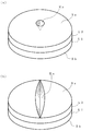
- FIG. 1 is a diagram showing an example of an embodiment of the laminated tablet of the present invention.
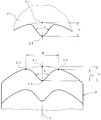
- FIG. 2 is a cross-sectional view showing a mortar and a pair of upper and lower ridges used for manufacturing the laminated tablet of the present invention.
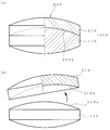
- FIG. 3 is a perspective view showing a typical example of a recess.
- FIG. 4 is a diagram showing an example of a pattern drawn by the recess when the surface (the upper surface in the example in the figure) on which the recess is formed is viewed from the front.
- FIG. 5 is a cross-sectional view for defining the dimensions of each part of the concave part and the dimension of the convex part of the ridge when the upper surface of the multilayer tablet is a hemispherical curved surface.
- FIG. 6 is a diagram showing a state in which each layer in the laminated tablet is sequentially formed in the conventional tableting process of the laminated tablet.
- FIG. 7 is a diagram showing the structure and problems of a conventional
- FIG. 1 is a diagram schematically showing one structural example of the laminated tablet.
- a structural example of a two-layered tablet composed of a first layer L1 and a second layer L2 is shown.
- the upper surface Sa of the entire laminated tablet is also the upper surface S2a of the second layer L2
- the lower surface Sb of the entire laminated tablet is also the lower surface S1b of the first layer L1.
- the said laminated tablet is provided with the recessed part Ka of 0.1 mm or more in depth on at least one surface (upper surface Sa in the example of the figure) of the front and back both surfaces. , Thereby delamination is suppressed.
- the figure also shows the method for suppressing delamination of the present invention.
- a recess having a depth of 0.1 mm or more is provided on at least one of the front and back surfaces of the laminated tablet, and the formation of the recess increases the adhesion between layers and suppresses delamination.
- the concave portion Ka is provided on the upper surface Sa formed by the upper collar in terms of improving the interlayer adhesion.
- a similar recess K1 is also formed on the upper surface S1a of L1 by temporary pressing. That is, as shown in FIG. 2, when the recess Ka is formed on the upper surface Sa, the upper surface S1a and S2a of all the layers L1 and L2 other than the uppermost layer L3 are also formed in the recess Ka by the temporary pressing of the upper collar.
- the recesses K1 and K2 having the same shape are formed, and the material of the next layer enters the recesses, thereby further improving the interlayer adhesion.
- FIG. 1B and FIG. 2 an embodiment in which a concave portion is provided on the upper surface will be described.
- the description about the shape of each part of a tablet and the shape of a recessed part is shared with the description about the shape
- the external shape of the tablet is the internal shape of the mortar
- the degree of swelling of the upper and lower surfaces of the tablet is the degree of depression of the upper and lower eyelids, respectively, and the pattern, depth, internal
- the shape of all the parts such as the angle of the slope of the slope, the width of the mouth, etc. It corresponds to the shape of all parts such as the pattern, height, angle of the slope of the outer surface, and width of the base.
- the interlayer adhesion improves according to the respective numerical values and forms.
- the depth of the recess be 0.1 mm or more as a condition for obtaining an interlayer adhesion useful for quality control of an actual laminated tablet. If the depth of the recess is less than 0.1 mm, even if the recess is a V-groove, sufficient interlayer adhesion cannot be obtained for quality control.
- the depth of the recess that can more effectively suppress delamination varies depending on the mode of the recess (such as holes and grooves described later), but in terms of the general thickness of each layer of the laminated tablet and the amount of protrusion of the wrinkles,
- the depth is preferably 0.1 mm to 0.4 mm, more preferably 0.2 mm to 0.4 mm, and particularly preferably 0.3 mm to 0.4 mm.
- the width of the recess is preferably 0.6 mm to 2.0 mm, and more preferably 0.7 mm to 1.7 mm. The definition of the depth of the recess and the width of the recess will be described later with reference to FIG.
- the shape of the concave portion may be a single hole-shaped concave portion as shown in FIG. 3 (a). However, if the concave portion is a groove-shaped concave portion as shown in FIG. Since it is larger, the contact surface between the inner wall surface of the recess and the projection of the next layer that has entered the layer interface becomes larger at the layer interface, and the interlayer adhesion is further improved. Moreover, if the projection of the next layer that has entered the recess is also a groove-like recess, the mechanical strength of the base of the projection is increased, and shear fracture is suppressed, which is preferable.
- the inner wall area equivalent to the groove-shaped concave portion and the mechanical strength of the base portion may be secured by providing a plurality of single hole-shaped concave portions.
- the convex portion of the upper collar for forming the concave portion is a ridge line-shaped projection for forming the groove-shaped concave portion, rather than a single shape such as a conical projection.
- FIG. 4 is a diagram showing an example of a pattern drawn by the recess when the surface (the upper surface in the example in the figure) on which the recess is formed is viewed from the front.
- FIG. 4A is an example in which a plurality of the single hole-shaped concave portions shown in FIG. The point at the center of the circle representing each hole-shaped recess suggests the point at the bottom of the conical (V-shaped cross section) hole.
- FIG. 4B is an example of a groove-shaped recess along a straight line passing through the center point of the upper surface, and the groove-shaped recess is formed only at the center of the upper surface.
- FIG. 4A is an example in which a plurality of the single hole-shaped concave portions shown in FIG. The point at the center of the circle representing each hole-shaped recess suggests the point at the bottom of the conical (V-shaped cross section) hole.
- FIG. 4B is an example of a groove-shaped recess along a straight line passing through
- FIG. 4C is an example of a groove-like recess (V-shaped groove) along a curve passing through the center point of the upper surface.
- a straight line drawn so as to advance in the center of the groove suggests a bottom line of the V-shaped groove.
- FIG. 4D shows an example in which a groove-like recess is formed on the upper surface so as to draw letters and symbols. In the example of the figure, the letter “T” is drawn.
- channel of another figure can also be considered as a character and a code
- 3 and 4 are merely representative examples, and the number, shape, and arrangement pattern of the recesses may be determined in consideration of adhesion strength, workability of the upper eyelid, appearance, and the like.
- a linear groove-like recess extending over the entire diameter of the tablet as shown in FIG. 3 (b) is a preferable mode for efficiently imparting a suppression effect to the entire tablet.
- the actual recesses that can be formed on the upper surface of the laminated tablet have a V-shaped cross section as shown in FIG. 2 and FIG. It is preferable that the V-shaped bottom and the shoulder of the opening are appropriately rounded. Further, as described above, the recess is preferably groove-shaped rather than a single hole. Therefore, a preferred form of the recess is a V-shaped groove (a groove having a V-shaped cross section when cut perpendicular to the longitudinal direction of the groove). However, the fact that the convex part of the upper collar is easy to come out of the concave part after tableting is likely to cause layer separation.
- the angle inside the V-shape is easy to remove the upper collar and enters the convex part or concave part of the upper collar. It is preferable that the protrusions of the next layer have a high strength and have an angle at which layer separation hardly occurs. From these points, the angle ⁇ inside the V-shape shown in FIG. 5 is preferably 40 to 110 degrees, more preferably 50 to 100 degrees, and particularly preferably 70 to 100 degrees. If the angle ⁇ is less than 40 degrees, the convex part of the upper eyelid or the protruding part entering the concave part from the next layer becomes sharp, and the problem that the strength decreases and the amount of powder entering the concave part decreases. The problem that the effect is reduced becomes significant. On the other hand, when the angle ⁇ exceeds 110 degrees, the convex portion is easily removed from the concave portion after tableting, and layer separation is likely to occur.
- the concave portions formed on the upper surface of the laminated tablet are different in terms of the width and the angle inside the V-shape, as compared with the characters and symbols formed as stamps on the conventionally known tablets.
- the depth of the recess may be determined by measuring the distance from the flat surface to the deepest portion of the recess.
- the depth of the concave portion referred to in the present invention is from the design peak portion Z1 of the curved surface of the upper surface, It is the distance d to the deepest part Z2 of a recessed part.
- an intersection Z1 between the upper surface curve and the center line Y of the recess may be determined in a drawing manner in the cross section of the recess.
- the upper surface exhibits another curved surface.
- the distance d from the design peak portion Z1 of the curved surface of the bulge on the upper surface to the deepest portion Z2 of the concave portion and [the peak portion Z3 (or Z3 ′) of the shoulder portion of the concave portion opening]
- the step (height difference) d1] from the deepest portion Z2 of the concave portion is about 0.05 mm or less, which is extremely small.
- the height of the convex portion of the ridge used for forming the concave portion is the same as the depth of the concave portion, and when the pressing surface of the ridge P1 is a flat surface, the height of the convex portion is from the flat surface to the tip of the convex portion.
- the pressure surface of the ridge P1 is a hemispherical curved surface as shown in FIG. 5, from the design peak portion Z4 of the concave curved surface to the apex Z5 of the convex portion Is a distance h. Further, as shown in FIG.
- the “width of the concave portion” refers to the peak portion Z3 of the shoulder portion of the opening of the concave portion on the upper surface (or lower surface) of the laminated tablet and the peak portion Z3 ′ of the other shoulder portion. The distance W between them.
- Whether or not a concave portion is formed on the upper surface of the layer other than the uppermost layer of the laminated tablet is determined by observing the structure of the cross-section of the laminated tablet, particularly the state of the layer interface, by analysis using X-ray CT or terahertz waves. You can confirm it.
- the interface of the layer can be identified from the difference in appearance caused by the difference in the prescription and the minute voids in the interface, and the recess can be found by following the interface.
- a recessed part can be found similarly by cut
- the outer peripheral shape and the size, thickness, and number of layers of the laminated tablet are the same as those of conventionally known laminated tablets.
- the outer peripheral shape of a laminated tablet conventionally used as a pharmaceutical is mainly circular or elliptical.
- the diameter is mainly 4 mm to 10 mm
- the thickness is mainly 2 mm to 6 mm
- the number of layers is mainly 2 to 3.
- the ratio of the thickness of each layer varies depending on the characteristics of the formulation.
- the laminated tablet may be one in which a known film coating is further applied to the surface of the uncoated tablet. In that case, the depth of the recess is the depth immediately after tableting (uncoated tablet).
- a projection having a height of 0.1 mm or more for forming the above-described recess at least on the mold surface (pressurized surface) of the upper collar P1 Part Pk is provided.
- the powder material into the mortar is put into each layer in the same manner as in the conventional tableting procedure for laminated tablets shown in FIGS. 6 (A) to (G).
- the temporary pressurization is performed, and the final pressurization is finally performed to complete the laminated tablet.
- concave portions having the same shape having a depth of 0.1 mm or more are formed on the upper surfaces of all layers.
- the material of the next layer enters the recesses on the upper surfaces of all the layers (L1, L2) other than the uppermost layer (L3), thereby forming a stacked structure in which layer separation is suppressed.
- the values of temporary pressurization and main pressurization for each layer may be the same as those used in the conventional tableting process of laminated tablets.
- the temporary pressure is preferably about 1 to 5 kN
- the main pressure is preferably about 3 to 20 kN.
- the laminated tablet may be a drug, a quasi drug, a cosmetic, a food (including supplements), a reagent, and the like, and its use is not limited.
- compositions are suitable for use in the form of laminated tablets.
- the laminated tablet can be used for the preparation of various pharmaceutically active ingredients.
- suitable specific examples of such pharmaceutically active ingredients include the following: Diabetes [eg, type 1 diabetes, type 2 diabetes, type 1.5 diabetes (LADA (Latent Autoimmune Diabetes in Adults)), gestational diabetes, insulin secretion deficiency type diabetes, obesity type diabetes, impaired glucose tolerance (IGT (Impaired Glucose Tolerance) )), IFG (Impaired Fasting Glucose), IFG (Impaired Fasting Glycaemia), borderline diabetes mellitus], alogliptin or a salt thereof (preferably benzoate), pioglitazone or a salt thereof (preferably, Hydrochloride), metformin or a salt thereof (preferably hydrochloride), 2-((6-((3R) -3-aminopiperidin-1-yl) -3-methyl-2,4-dioxo-3,4 -Dihydropyrimidin-1 (2H) -yl) methyl) -4
- Examples of the salt of the above compound include pharmacologically acceptable salts such as salts with inorganic acids, salts with organic acids, salts with basic or acidic amino acids, and the like.
- Preferable examples of the salt with inorganic acid include salts with hydrochloric acid, hydrobromic acid, nitric acid, sulfuric acid, phosphoric acid and the like.
- Preferable examples of salts with organic acids include benzoic acid, formic acid, acetic acid, trifluoroacetic acid, fumaric acid, oxalic acid, tartaric acid, maleic acid, citric acid, succinic acid, malic acid, methanesulfonic acid, and benzenesulfonic acid.
- salts with p-toluenesulfonic acid and the like Preferable examples of the salt with basic amino acid include salts with arginine, lysine, ornithine and the like, and preferable examples of the salt with acidic amino acid include salts with aspartic acid, glutamic acid and the like.
- the laminated tablet may further contain additives commonly used in the pharmaceutical field.
- the additive include an excipient, a disintegrant, a binder, a lubricant, a colorant, a pH adjuster, a surfactant, a stabilizer, a sour agent, a fragrance, a fluidizing agent, a coating base, Examples thereof include coating additives. These additives are used in amounts conventionally used in the pharmaceutical field unless otherwise specified.
- excipients examples include sugars or sugar alcohols such as lactose, fructose, glucose, mannitol, sorbitol; corn starch, potato starch, wheat starch, rice starch, partially pregelatinized starch, pregelatinized starch, porous starch, etc.
- Starch crystalline cellulose (eg, microcrystalline cellulose); anhydrous calcium phosphate, precipitated calcium carbonate, calcium silicate, and the like.
- the excipient is preferably used in an amount of 5 to 95% by weight based on 100 parts by weight of the laminated tablet of the present invention.
- the disintegrant include carboxymethyl cellulose, carboxymethyl cellulose calcium, carboxymethyl starch sodium, croscarmellose sodium, carmellose calcium, crospovidone, low-substituted hydroxypropyl cellulose, hydroxypropyl starch and the like.
- the amount of the disintegrant used is preferably 0.5 to 25 parts by weight with respect to 100 parts by weight of the laminated tablet of the present invention.
- the binder include hydroxypropyl cellulose (eg, grade: L, SL, SL-T, SSL (trade name); Nippon Soda Co., Ltd.), hydroxypropyl methylcellulose (eg, hypromellose 2910 (eg, TC) -5 (grade: MW, E, EW, R, RW) (trade name); Shin-Etsu Chemical Co., Ltd.)), polyvinylpyrrolidone (Povidone), gum arabic hydroxypropylcellulose, hydroxypropylmethylcellulose, polyvinylpyrrolidone, gum arabic, etc. Is mentioned.
- the binder is preferably used in an amount of 1 to 20% by weight based on 100 parts by weight of the laminated tablet of the present invention.
- the lubricant include magnesium stearate, calcium stearate, talc, sucrose fatty acid ester, sodium stearyl fumarate and the like.
- the lubricant is used in an amount of 0.5 to 2% by weight based on 100 parts by weight of the solid preparation.
- the colorant include edible dyes (eg, edible yellow No. 5, edible red No. 2, edible blue No. 2), edible lake dyes, iron sesquioxide, yellow sesquioxide, and the like.
- the pH adjuster include citrate, phosphate, carbonate, tartrate, fumarate, acetate, amino acid salt and the like.
- the surfactant include sodium lauryl sulfate, polysorbate 80, polyoxyethylene (160) polyoxypropylene (30) glycol and the like.
- the stabilizer include tocopherol, tetrasodium edetate, nicotinamide, cyclodextrins and the like.
- Preferable examples of the acidulant include ascorbic acid, citric acid, tartaric acid, malic acid and the like.
- Preferable examples of the flavor include menthol, mint oil, lemon oil, vanillin and the like.
- Preferable examples of the fluidizing agent include light anhydrous silicic acid, hydrous silicon dioxide, talc and the like.
- the coating base include sugar coating base, water-soluble film coating base, enteric film coating base, sustained-release film coating base and the like.
- sugar coating base sucrose is used, and one or more selected from talc, precipitated calcium carbonate, gelatin, gum arabic, pullulan, carnauba wax and the like may be used in combination.
- water-soluble film coating base examples include hydroxypropyl cellulose (eg, grade: L, SL, SSL (trade name); Nippon Soda Co., Ltd.), hydroxypropyl methylcellulose (eg, hypromellose 2910 (eg, TC-5) (Grade: MW, E, EW, R, RW) (trade name); Shin-Etsu Chemical Co., Ltd.), cellulose-based polymers such as hydroxyethyl cellulose and methylhydroxyethyl cellulose; polyvinyl acetal diethylaminoacetate, aminoalkyl methacrylate copolymer E [Eudragit E (trade name)], synthetic polymers such as polyvinylpyrrolidone; polysaccharides such as pullulan.
- hydroxypropyl cellulose eg, grade: L, SL, SSL (trade name); Nippon Soda Co., Ltd.
- hydroxypropyl methylcellulose eg, hypromellose 2910
- enteric film coating bases include cellulose polymers such as hydroxypropylmethylcellulose phthalate, hydroxypropylmethylcellulose acetate succinate, carboxymethylethylcellulose, and cellulose acetate phthalate; methacrylic acid copolymer L [Eudragit L (trade name) ], Acrylic acid polymers such as methacrylic acid copolymer LD [Eudragit L-30D55 (trade name)], methacrylic acid copolymer S [Eudragit S (trade name)]; natural products such as shellac.
- the sustained-release film coating base examples include cellulose polymers such as ethyl cellulose; aminoalkyl methacrylate copolymer RS [Eudragit RS (trade name)], ethyl acrylate / methyl methacrylate copolymer suspension [ And acrylic acid polymers such as Eudragit NE (trade name)].
- Suitable examples of the coating additive include a light-shielding agent such as titanium oxide; a fluidizing agent such as talc; a colorant such as iron sesquioxide and yellow sesquioxide; polyethylene glycol (eg, Macrogol 6000), and triethyl citrate.
- plasticizers such as castor oil and polysorbates; organic acids such as citric acid, tartaric acid, malic acid, and ascorbic acid. Two or more kinds of film coating materials may be mixed and used at an appropriate ratio.
- the laminated tablet can be safely administered orally or parenterally to mammals (eg, mouse, rat, rabbit, cat, dog, cow, horse, monkey, human).
- mammals eg, mouse, rat, rabbit, cat, dog, cow, horse, monkey, human.
- the dose of the laminated tablet may be an effective amount of a pharmaceutically active ingredient. This amount can be administered in one to several times a day (eg, 1 to 3 times).
- Example 1 In this example, a sample of a laminated tablet having a V-shaped groove formed as a concave portion on the upper surface and / or the lower surface was prepared, and the angle and depth of the V-shaped groove were changed to compare with a sample in which no concave portion was formed. The degree of delamination was suppressed (how much the interlayer adhesion was improved).
- the outer peripheral shape is a circular shape with a diameter of 8.5 mm, the upper and lower surfaces are both raised to a spherical surface, the height of the raised portion with respect to the outer peripheral edge is 1.4 mm, and the total maximum thickness is 5 mm.
- sample formation In order to compress the sample, various types of upper and lower punches having convex portions (ridge line-like protrusions) corresponding to the respective shapes of the V-shaped grooves on the pressing surface were prepared. For comparison, upper and lower eyelids not forming convex portions were also prepared.
- Tabletting into two-layer tablets The mixture A was tableted with a tableting machine for two-layer tablets [HT-X65LD-UW / 2L, manufactured by Hata Iron Works Co., Ltd.] (tablet size: diameter 8.5 mm, compression pressure 1 kN / ⁇ ). A tablet (mass: 180 mg / tablet) as the first layer was produced. Subsequently, the tablet A was filled with the mixture A and tableted (compression pressure: 10 kN / kg) to laminate the second layer on top of the first layer. Alogliptin benzoate 17 mg / pioglitazone hydrochloride per tablet A two-layer tablet (mass: 280 mg / tablet) containing 16.53 mg of the salt was obtained. The details of the prescription amount of each layer per tablet are shown in Table 1 below.
- the shape of the recess is a straight V-groove across the diameter of the tablet, the angle inside the V-shaped is (70 degrees, 100 degrees), and the depth of the V-shaped groove is (0.1 mm, 0.00 mm). 2 mm, 0.3 mm, and 0.4 mm). For comparison, a sample in which no recess was formed was also prepared.
- Test method for determining the degree of delamination In order to investigate the degree of delamination, this test has the same structure as the device specified in the 15th revision of the Japanese Pharmacopoeia "Tablet Friction Test Method", but differs only in drum material and dimensions. A device was made.
- the manufactured test device is a device having a hollow drum whose horizontal axis of rotation is held horizontally and can be rotated by an electric motor. A sample tablet is placed inside the drum, and the drum is rotated a predetermined number of times at a predetermined speed. Then, the degree of delamination of the laminated tablet with respect to impact is observed by raising and dropping the tablet inside the drum.
- One partition plate extending from the rotation center to the outer peripheral wall is provided inside the drum so that the tablets can be lifted.
- the material of the drum is plastic
- the inner diameter is about 287 mm
- the depth is about 38 mm.
- a part of the material of the inner wall of the drum is stainless steel.
- the inner diameter is about 500 mm and the depth is about 60 mm.
- the mixture was stirred at 45-55 ° C. for 3-7 hours or until the end of the reaction.
- the solution was cooled to 25 to 35 ° C., and isopropanol (5.8 times volume, 4.6 wt.) Was added while maintaining 25 to 35 ° C.
- Water (4 times amount) was added while maintaining the internal temperature at 25 to 35 ° C., and the mixture was stirred for about 30 minutes. Cool to 0-5 ° C. and then stir for at least 1 hour.
- the obtained slurry was filtered, washed with isopropanol (4.4 times amount, 3.5 wt.) Cooled to 0 to 5 ° C., and vacuum-dried at 60 ° C. or lower to obtain the compound (2a).
- the inorganic salt was removed by filtration and the filter cake was washed with hot (eg, 45-55 ° C.) isopropanol.
- THF was added and acidified with 35% hydrochloric acid while maintaining the internal temperature at 10 to 20 ° C.
- the resulting slurry was cooled to 0-5 ° C., stirred until crystals grew (eg, over 1 hour), and then filtered.
- the filter cake was washed with isopropanol (6 volumes) and dried until the HCl salt of compound (3a) was obtained as a white crystalline solid.
- the mixture was stirred at 60-70 ° C. for 2-4 hours or until the end of the reaction.
- the solution is then cooled to 40-50 ° C., stirred for at least 30 minutes, and then isopropanol (1.5 times volume) and water (3.5 times volume) are added while maintaining 40-50 ° C., and then stirred for at least 1 hour. did.
- the solution was cooled to 20-30 ° C. and then stirred for at least 1 hour.
- the solution was cooled to 0-10 ° C. and then stirred for at least 1 hour.
- the obtained slurry was filtered, washed with isopropanol (4.0 times amount) cooled to 0 to 10 ° C., and vacuum dried at 45 to 55 ° C. to obtain the above compound (2b).
Abstract
Description
積層錠剤(積層錠などとも呼ばれる)は、2以上の層からなる積層構造を有する錠剤であり、例えば、配合剤の剤形の1つとして用いられている(特許文献1)。
積層錠剤は、一般的な素錠などと同様、粉末材料を圧縮(打錠)することによって形成される。図6は、積層錠剤が打錠によって形成されていく様子を模式的に示した打錠装置の断面図であり、同図では2層の積層錠剤を打錠する場合を例として挙げている。 (Background of the Invention)
A laminated tablet (also referred to as a laminated tablet) is a tablet having a laminated structure composed of two or more layers, and is used, for example, as one of dosage forms of a compounding agent (Patent Document 1).
A laminated tablet is formed by compressing (tabletting) a powder material, like a general uncoated tablet. FIG. 6 is a cross-sectional view of a tableting device schematically showing how a laminated tablet is formed by tableting. In this figure, a case where two layers of laminated tablets are compressed is shown as an example.
先ず、図6(B)に示すように、下杵P20と臼Q10とによって定められた空間に、ホッパーH10から第一層用の粉末材料100が定量投入され、図6(C)に示すように、上杵P10がロールR110に従動して下降し、ロールR120に支持された下杵P20と、前記上杵P10とによって粉末材料100が仮加圧され、中間圧縮状態の第一層110が形成される。
図6の例は、上杵P10と下杵P20のそれぞれの加圧面が、共に凹状となっている場合の例、即ち、錠剤の両面が凸状に膨らんでいる場合の例である。よって、この例では、第一層110の上面は、上杵P10の凹状の加圧面に押されて凸状の曲面となっている。
次に、図6(D)に示すように、第一層110の上面と臼Q10とによって定められた空間内に、ホッパーH20から第二層用の粉末材料200が定量投入され、図6(E)に示すように、上杵P10がロールR210に従動して下降し、ロールR120に支持された下杵P20と、前記上杵P10とによって粉末材料200が仮加圧され、中間圧縮状態の第二層210が形成される。この第二層210の上面は、錠剤全体の上面でもあり、第一層110の上面と同様、上杵P10の加圧面に押されて凸状の曲面となっている。
さらに、図6(F)に示すように、上杵P10がロールR310に従動して最終位置まで下降し、ロールR320に支持された下杵P20と、前記上杵P10とによって、第一層と第二層とからなる積層体が本加圧され、目的の積層錠剤300が完成し、図6(G)に示すように、下杵P20が上昇して積層錠剤300が臼外へと取り出される。 As shown in FIG. 6 (A), a combination of a cylindrical mortar Q10 and upper and lower ridges (upper heel P10 and lower heel P20) is provided on the rotating disk T10, and the following FIG. As shown in (G) to (G), while the mortar and pestle set proceeds according to the rotation of the table, the powder material is gradually introduced into the mortar, and temporary addition is performed by the upper and lower ridges after each addition. Pressing and final final pressing are performed, and the laminated
First, as shown in FIG. 6 (B), the
The example of FIG. 6 is an example in which the pressure surfaces of the upper eyelid P10 and the lower eyelid P20 are both concave, that is, an example in which both surfaces of the tablet swell in a convex shape. Therefore, in this example, the upper surface of the
Next, as shown in FIG. 6D, the
Further, as shown in FIG. 6 (F), the upper punch P10 is moved to the final position by following the roll R310, and the lower punch P20 supported by the roll R320 and the upper punch P10 The laminated body composed of the second layer is fully pressurized, and the target laminated
このような層剥離を抑制するために、従来では、例えば、層間密着力を高めるために処方や粉末特性を工夫するといった対策がとられている。
しかしながら、上記のような対策では、層剥離を十分に抑制するには至っていない。 As shown in FIG. 7 (a), the upper surface of the
In order to suppress such delamination, conventionally, for example, measures have been taken such as devising the formulation and powder characteristics in order to increase interlayer adhesion.
However, the above countermeasures have not sufficiently suppressed delamination.
(1)積層錠剤の表裏両面のうちの少なくとも一方の面に、深さ0.1mm以上の凹部が設けられていることを特徴とする、前記積層錠剤;
(2)上記凹部が形成された一方の面を有する層を最上層として、
該最上層以外の全ての各層が、それら各層の両面のうちの最上層側の面に、上記凹部と同じ形状の凹部を有しており、かつ、それら凹部内には次層の材料が入り込んでいる、上記(1)記載の積層錠剤;
(3)上記凹部が、1以上の溝状凹部である、上記(1)または(2)記載の積層錠剤;
(4)上記凹部が形成された一方の面を正視したときに、該面の中心点を通過する直線または曲線に沿った溝状凹部が存在している、上記(1)ないし(3)のいずれか記載の積層錠剤;
(5)上記溝状凹部が、上記一方の面の外周縁上の1点から、該面の中心点を通過し、外周縁上の反対側の点まで延びている、上記(1)ないし(4)のいずれか記載の積層錠剤;
(6)上記溝状凹部が、V字溝である、上記(1)ないし(5)のいずれか記載の積層錠剤;
(7)上記V字溝のV字の内側の角度が40度~110度である、上記(6)記載の積層錠剤;
(8)打錠工程で用いられる一対の杵のうち、上記一方の面を加圧する杵である上杵には、その型面に、上記凹部を形成するための高さ0.1mm以上の凸部が設けられており、
当該積層錠剤中の全ての層が、順次の打錠の際に、同じ上杵によって直接的な加圧を受けており、それによって、上記最上層以外の全ての各層の両面のうちの最上層側の面にも、上記一方の面の凹部と同じ形状の凹部が形成され、かつ、それら各層の凹部内には次層の材料が入り込んでいる、上記(2)ないし(7)のいずれか記載の積層錠剤;
(9)上記(1)記載の積層錠剤の製造方法であって、
下杵の型面上に、前記積層錠剤中の各層を順次積層し、上杵によって打錠する工程を有し、
少なくとも上杵には、その型面に高さ0.1mm以上の凸部が設けられており、
前記打錠する工程は、当該積層錠剤中の全ての層に対して前記上杵によって加圧する工程を有し、
前記加圧する工程によって、全ての層の両面のうち上杵側の面に深さ0.1mm以上の同じ形状の凹部が形成され、かつ、最上層以外の全ての層の凹部内に次層の材料が入り込んだ、積層構造が形成されることを特徴とする、
前記製造方法;
(10)積層錠剤の層剥離を抑制する方法であって、
積層錠剤の表裏両面のうちの少なくとも一方の面に、深さ0.1mm以上の凹部を設けることを特徴とする、層剥離抑制方法;
(11)下杵の型面上に、積層錠剤中の各層を順次積層し、上杵によって打錠し、前記積層錠剤を形成するに際し、
少なくとも上杵に、その型面に高さ0.1mm以上の凸部を設けておき、
前記積層錠剤中の全ての層を前記上杵によって加圧することによって、全ての層の両面のうち上杵側の面に深さ0.1mm以上の同じ形状の凹部を形成し、かつ、最上層以外の全ての層の前記凹部内に次層の材料が入り込んだ積層構造を形成することを特徴とする、上記(10)記載の方法;
等である。 That is, the present invention
(1) The laminated tablet, wherein a concave portion having a depth of 0.1 mm or more is provided on at least one of the front and back surfaces of the laminated tablet;
(2) A layer having one surface on which the concave portion is formed as an uppermost layer,
All the layers other than the uppermost layer have concave portions having the same shape as the concave portion on the uppermost surface side of both surfaces of the respective layers, and the material of the next layer enters the concave portions. A laminated tablet according to (1) above;
(3) The laminated tablet according to (1) or (2), wherein the concave portion is one or more groove-shaped concave portions;
(4) When the one surface on which the concave portion is formed is viewed from the front, there is a groove-shaped concave portion along a straight line or a curve passing through the center point of the surface, the above (1) to (3) Any laminated tablet;
(5) The groove-shaped recess extends from one point on the outer peripheral edge of the one surface to the opposite point on the outer peripheral edge through the center point of the surface. 4) The laminated tablet according to any one of
(6) The laminated tablet according to any one of (1) to (5), wherein the groove-shaped recess is a V-shaped groove;
(7) The laminated tablet according to the above (6), wherein the angle inside the V shape of the V groove is 40 degrees to 110 degrees;
(8) Of the pair of scissors used in the tableting process, the upper reed that pressurizes the one surface has a convexity with a height of 0.1 mm or more on the mold surface to form the recess. Part is provided,
All layers in the laminated tablet are directly pressed by the same upper punch during sequential tableting, so that the uppermost layer of both surfaces of all the layers other than the uppermost layer is Any one of the above (2) to (7), in which a concave portion having the same shape as the concave portion on the one surface is formed on the side surface, and the material of the next layer enters the concave portion of each layer. The laminated tablet as described;
(9) A method for producing a laminated tablet according to (1) above,
On the mold surface of the lower punch, each layer in the laminated tablet is sequentially stacked, and has a step of tableting with the upper punch,
At least the upper collar is provided with a convex portion having a height of 0.1 mm or more on the mold surface,
The step of tableting includes the step of pressing with the upper punch on all layers in the laminated tablet,
By the pressurizing step, a concave portion having the same shape with a depth of 0.1 mm or more is formed on the surface of the upper collar among both surfaces of all layers, and the next layer is formed in the concave portions of all layers other than the uppermost layer. A layered structure is formed in which the material enters,
Said manufacturing method;
(10) A method for suppressing delamination of a laminated tablet,
A method for inhibiting delamination, comprising providing a recess having a depth of 0.1 mm or more on at least one of the front and back surfaces of the laminated tablet;
(11) On the mold surface of the lower punch, each layer in the stacked tablet is sequentially stacked, and compressed with the upper punch to form the stacked tablet.
At least on the upper collar, a convex part having a height of 0.1 mm or more is provided on the mold surface,
By pressing all the layers in the laminated tablet with the upper punch, concave portions having the same shape with a depth of 0.1 mm or more are formed on the upper flange side surface of both surfaces of the layers, and the uppermost layer The method according to (10) above, wherein a laminated structure in which the material of the next layer enters into the recesses of all layers other than the above is formed;
Etc.
以下、説明の便宜上、当該積層錠剤の表裏の面のうち、打錠工程において上杵によって形成される面を「上面」と呼び、その「上面」に対する錠剤の反対側の面を「下面」と呼んで、当該積層錠剤の積層方向に上下の方向を与えて説明を行う。この上下の方向に準じて、積層錠剤中の各層の表裏の面についても、「層の上面」、「層の下面」と呼ぶ。
また、打錠工程において、臼内の下杵の上に仮加圧にて形成される最初の層を、「最下層」または「第一層」と呼び、その上に形成される層を、順次「第二層」、「第三層」、...、「第n層」というように層に番号を与えて呼び、最後に形成される「第n層」を「最上層」とも呼ぶ。また、下層側に位置する1つの層に対して、直接隣接する直上の層を「次層」と呼ぶ。 The layered tablet of the present invention, in terms of the basic tableting process, as in the prior art, the first layer is formed in the mortar by temporary pressing, and then the next layer is temporarily pressed for each layer, Finally, the main pressure is applied to form a laminate.
Hereinafter, for convenience of explanation, of the front and back surfaces of the laminated tablet, the surface formed by the upper punch in the tableting process is referred to as “upper surface”, and the surface on the opposite side of the tablet with respect to the “upper surface” is referred to as “lower surface”. The explanation is given by giving up and down directions in the lamination direction of the laminated tablets. According to this vertical direction, the front and back surfaces of each layer in the laminated tablet are also referred to as “upper surface of layer” and “lower surface of layer”.
In the tableting process, the first layer formed by temporary pressing on the lower punch in the mortar is called the “lowermost layer” or “first layer”, and the layer formed thereon is Sequentially “second layer”, “third layer”,. . . The “nth layer” is referred to by giving a number to the layer, and the “nth layer” formed last is also referred to as the “top layer”. In addition, a layer directly adjacent to one layer located on the lower layer side is referred to as a “next layer”.
即ち、図2に3層の積層錠剤の例を示すように、積層錠剤Mの上面Saに凹部Kaを形成するということは、打錠の際の上杵P1の加圧面Psに、該凹部Kaに対応する凸部Pkを形成することを意味する。上杵の加圧面にそのような凸部を形成すれば、打錠工程では各層毎に仮加圧が行われるので、最上層L3の上面Sa(=S3a)のみならず、各層の上面(第一層L1の上面S1aと、第二層L2の上面S2a)にも、仮加圧による同様の凹部K1、K2がそれぞれに形成され、次層の粉末材料がそれぞれの凹部内に入り込み、押し固められて、2層間の密着力が高くなる。 The present invention is characterized in that a recess is provided on at least “one surface” of the front and back surfaces of the laminated tablet. The surface on which the concave portion is necessarily provided may be either the front or back surface, but providing the concave portion on the upper surface, which is the surface formed by the upper punch in the tableting process, improves interlayer adhesion and delaminates the surface. This is a more preferable aspect in terms of suppression.
That is, as shown in FIG. 2 showing an example of a three-layer laminated tablet, the formation of the concave portion Ka on the upper surface Sa of the laminated tablet M means that the concave portion Ka is formed on the pressing surface Ps of the upper punch P1 during tableting. It means that the convex part Pk corresponding to is formed. If such a convex portion is formed on the pressing surface of the upper collar, temporary pressing is performed for each layer in the tableting process, so that not only the upper surface Sa (= S3a) of the uppermost layer L3 but also the upper surfaces (first On the upper surface S1a of the first layer L1 and the upper surface S2a of the second layer L2, similar concave portions K1 and K2 are formed by temporary pressing, respectively, and the powder material of the next layer enters into each concave portion and is compacted. As a result, the adhesion between the two layers increases.
以下、図を参照しながら、本発明による積層錠剤の構造とその製造方法、および、層剥離抑制方法を説明する。
図1は、当該積層錠剤の一構造例を模式的に示した図である。同図の例では、第1層L1と第2層L2とからなる2層の積層錠剤の構造例を示している。図1(b)のとおり、積層錠剤全体の上面Saは第2層L2の上面S2aでもあり、同様に、積層錠剤全体の下面Sbは、第1層L1の下面S1bでもある。
図1(a)に示すように、当該積層錠剤は、その表裏両面のうちの少なくとも一方の面(同図の例では上面Sa)に、深さ0.1mm以上の凹部Kaが設けられており、それによって層剥離が抑制されたものとなっている。
また、同図は、本発明の層剥離抑制方法をも表している。当該方法は、積層錠剤の表裏両面のうちの少なくとも一方の面に、深さ0.1mm以上の凹部を設け、該凹部の形成によって層間の密着力を高め、層剥離を抑制するものである。
上記作用の説明でも述べたとおり、この凹部Kaは、上杵によって形成される上面Saに設ける方が、層間密着力を向上させる点でより好ましい態様である。図1(b)の例では、最上層である第2層L2の上面S2a(=Sa)に、凹部Ka(=第2層L2の凹部K2)が形成されているだけでなく、第一層L1の上面S1aにも、仮加圧による同様の凹部K1が形成されている。即ち、図2に示すように、上面Saに凹部Kaを形成するとき、上杵の仮加圧によって、最上層L3以外の全ての層L1、L2の各上面S1a、S2aにも、該凹部Kaと同じ形状の凹部K1、K2が形成され、それら凹部内には次層の材料が入り込んで、層間密着力がより向上する。
以下、図1(b)、図2のように、上面に凹部を設ける態様について説明するが、下面に凹部を設ける場合の該凹部についての説明を兼用する。
また、錠剤の各部の形状、凹部の形状についての説明は、そのまま、それを打錠するための型である杵、臼の形状、杵に設けられる凸部の形状についての説明を兼用する。即ち、錠剤の外形は臼の内部形状であり、錠剤の上面、下面の膨らみの程度は、それぞれに、上杵、下杵の窪みの程度であり、錠剤の凹部の〔パターン、深さ、内部の斜面の角度、口元の幅〕など全ての部分の形状は、鋳型と鋳物の関係のように凹凸が反転した関係にて、それぞれに、該凹部を形成すべく杵に設けられる凸部の〔パターン、高さ、外面の斜面の角度、基部の幅〕など全ての部分の形状に対応する。 (Detailed description of the invention)
Hereinafter, the structure of a laminated tablet according to the present invention, a method for producing the same, and a method for suppressing delamination will be described with reference to the drawings.
FIG. 1 is a diagram schematically showing one structural example of the laminated tablet. In the example of the figure, a structural example of a two-layered tablet composed of a first layer L1 and a second layer L2 is shown. As shown in FIG. 1B, the upper surface Sa of the entire laminated tablet is also the upper surface S2a of the second layer L2, and similarly, the lower surface Sb of the entire laminated tablet is also the lower surface S1b of the first layer L1.
As shown to Fig.1 (a), the said laminated tablet is provided with the recessed part Ka of 0.1 mm or more in depth on at least one surface (upper surface Sa in the example of the figure) of the front and back both surfaces. , Thereby delamination is suppressed.
The figure also shows the method for suppressing delamination of the present invention. In this method, a recess having a depth of 0.1 mm or more is provided on at least one of the front and back surfaces of the laminated tablet, and the formation of the recess increases the adhesion between layers and suppresses delamination.
As described in the description of the above action, it is more preferable that the concave portion Ka is provided on the upper surface Sa formed by the upper collar in terms of improving the interlayer adhesion. In the example of FIG. 1B, not only the recess Ka (= the recess K2 of the second layer L2) is formed on the upper surface S2a (= Sa) of the second layer L2, which is the uppermost layer, but also the first layer. A similar recess K1 is also formed on the upper surface S1a of L1 by temporary pressing. That is, as shown in FIG. 2, when the recess Ka is formed on the upper surface Sa, the upper surface S1a and S2a of all the layers L1 and L2 other than the uppermost layer L3 are also formed in the recess Ka by the temporary pressing of the upper collar. The recesses K1 and K2 having the same shape are formed, and the material of the next layer enters the recesses, thereby further improving the interlayer adhesion.
Hereinafter, as shown in FIG. 1B and FIG. 2, an embodiment in which a concave portion is provided on the upper surface will be described.
Moreover, the description about the shape of each part of a tablet and the shape of a recessed part is shared with the description about the shape | mold of a tablet for compressing it as it is, the shape of a mortar, and the shape of the convex part provided in a ridge. In other words, the external shape of the tablet is the internal shape of the mortar, the degree of swelling of the upper and lower surfaces of the tablet is the degree of depression of the upper and lower eyelids, respectively, and the pattern, depth, internal The shape of all the parts, such as the angle of the slope of the slope, the width of the mouth, etc. It corresponds to the shape of all parts such as the pattern, height, angle of the slope of the outer surface, and width of the base.
層剥離をより効果的に抑制し得る凹部の深さは、凹部の態様(後述の穴や溝など)によっても異なるが、積層錠剤の各層の一般的な厚さや杵の突起量の点から、0.1mm~0.4mmが好ましく、0.2mm~0.4mmがより好ましく、0.3mm~0.4mmが特に好ましい深さである。
また、凹部の幅は、0.6mm~2.0mmが好ましく、0.7mm~1.7mmがより好ましい。
凹部の深さ、凹部の幅の定義については、図5を用いて後述する。 Regardless of the depth and pattern of the recess, the interlayer adhesion improves according to the respective numerical values and forms. However, in the present invention, it is recommended that the depth of the recess be 0.1 mm or more as a condition for obtaining an interlayer adhesion useful for quality control of an actual laminated tablet. If the depth of the recess is less than 0.1 mm, even if the recess is a V-groove, sufficient interlayer adhesion cannot be obtained for quality control.
The depth of the recess that can more effectively suppress delamination varies depending on the mode of the recess (such as holes and grooves described later), but in terms of the general thickness of each layer of the laminated tablet and the amount of protrusion of the wrinkles, The depth is preferably 0.1 mm to 0.4 mm, more preferably 0.2 mm to 0.4 mm, and particularly preferably 0.3 mm to 0.4 mm.
The width of the recess is preferably 0.6 mm to 2.0 mm, and more preferably 0.7 mm to 1.7 mm.
The definition of the depth of the recess and the width of the recess will be described later with reference to FIG.
尚、凹部の内壁面積をより大きくするという点からは、単発的な穴状凹部を複数設けることによって、溝状凹部と同等の内壁面積や基部の機械的強度を確保してもよい。ただし、凹部を形成するための上杵の凸部の形態に着目すると、該凸部は、溝状凹部を形成するための稜線状突起である方が、円錐状突起などの単発的な形態よりも加工がし易く、また、強度が高く寿命が長いという利点がある。 The shape of the concave portion may be a single hole-shaped concave portion as shown in FIG. 3 (a). However, if the concave portion is a groove-shaped concave portion as shown in FIG. Since it is larger, the contact surface between the inner wall surface of the recess and the projection of the next layer that has entered the layer interface becomes larger at the layer interface, and the interlayer adhesion is further improved. Moreover, if the projection of the next layer that has entered the recess is also a groove-like recess, the mechanical strength of the base of the projection is increased, and shear fracture is suppressed, which is preferable.
In addition, from the point of increasing the inner wall area of the concave portion, the inner wall area equivalent to the groove-shaped concave portion and the mechanical strength of the base portion may be secured by providing a plurality of single hole-shaped concave portions. However, paying attention to the shape of the convex portion of the upper collar for forming the concave portion, the convex portion is a ridge line-shaped projection for forming the groove-shaped concave portion, rather than a single shape such as a conical projection. Are easy to process, and have the advantages of high strength and long life.
図4(a)は、図3(a)に示した単発的な穴状の凹部を複数設けた例である。各穴状の凹部を表す円の中心の点は、円錐状(断面V字状)の穴の底の点を示唆している。
図4(b)は、上面の中心点を通過する直線に沿った溝状凹部の例であって、該溝状凹部は上面の中央部だけに形成されている。これに対して、図3(b)の例では、溝状凹部は上面の外周縁上の1点から中心点を通過し外周縁上の反対側の点まで延びている。
図4(c)は、上面の中心点を通過する曲線に沿った溝状凹部(V字溝)の例である。溝内の中央を進行するように描いた直線は、V字溝の底の線を示唆している。
図4(d)は、上面に文字や符号を描くように溝状凹部を形成した例である。同図の例では、「T」という文字を描いている。尚、他の図の穴や溝のパターンも、文字や符号と見なすことができ、適宜、組み合わせてもよい。
図3、図4に示した例は、あくまでも代表的な例であって、凹部の個数、形状、配置パターンは、密着強度、上杵の加工性、外観などを考慮し決定すればよい。これら凹部の種々のパターンの中でも、図3(b)のような、錠剤の直径全体にわたる直線的な溝状凹部は、錠剤の全体に効率的に抑制効果を付与するうえで好ましい態様である。 FIG. 4 is a diagram showing an example of a pattern drawn by the recess when the surface (the upper surface in the example in the figure) on which the recess is formed is viewed from the front.
FIG. 4A is an example in which a plurality of the single hole-shaped concave portions shown in FIG. The point at the center of the circle representing each hole-shaped recess suggests the point at the bottom of the conical (V-shaped cross section) hole.
FIG. 4B is an example of a groove-shaped recess along a straight line passing through the center point of the upper surface, and the groove-shaped recess is formed only at the center of the upper surface. On the other hand, in the example of FIG. 3B, the groove-shaped recess extends from one point on the outer peripheral edge of the upper surface to the opposite point on the outer peripheral edge through the center point.
FIG. 4C is an example of a groove-like recess (V-shaped groove) along a curve passing through the center point of the upper surface. A straight line drawn so as to advance in the center of the groove suggests a bottom line of the V-shaped groove.
FIG. 4D shows an example in which a groove-like recess is formed on the upper surface so as to draw letters and symbols. In the example of the figure, the letter “T” is drawn. In addition, the pattern of the hole and groove | channel of another figure can also be considered as a character and a code | symbol, and may be combined suitably.
The examples shown in FIGS. 3 and 4 are merely representative examples, and the number, shape, and arrangement pattern of the recesses may be determined in consideration of adhesion strength, workability of the upper eyelid, appearance, and the like. Among these various patterns of recesses, a linear groove-like recess extending over the entire diameter of the tablet as shown in FIG. 3 (b) is a preferable mode for efficiently imparting a suppression effect to the entire tablet.
ただし、上杵の凸部が打錠後に凹部から抜け易いということは、層分離も生じ易いので、V字の内側の角度は、上杵が抜き易く、上杵の凸部や凹部内に入り込む次層の突起部が高い強度を持ち、しかも、層分離が生じ難いような角度とすることが好ましい。これらの点から、図5に示すV字の内側の角度θは、40~110度が好ましく、50~100度がより好ましく、70~100度が特に好ましい角度である。角度θが40度未満であれば、上杵の凸部や、次層から凹部内に入り込んでいる突起部が鋭利になり、強度が低下するという問題や、凹部内に入り込む粉末量が少なくなり効果が小さくなるという問題が顕著になる。また、角度θが110度を超えると、凸部が打錠後に凹部から抜け易くなり、層分離が生じ易くなる。 The actual recesses that can be formed on the upper surface of the laminated tablet have a V-shaped cross section as shown in FIG. 2 and FIG. It is preferable that the V-shaped bottom and the shoulder of the opening are appropriately rounded. Further, as described above, the recess is preferably groove-shaped rather than a single hole. Therefore, a preferred form of the recess is a V-shaped groove (a groove having a V-shaped cross section when cut perpendicular to the longitudinal direction of the groove).
However, the fact that the convex part of the upper collar is easy to come out of the concave part after tableting is likely to cause layer separation. Therefore, the angle inside the V-shape is easy to remove the upper collar and enters the convex part or concave part of the upper collar. It is preferable that the protrusions of the next layer have a high strength and have an angle at which layer separation hardly occurs. From these points, the angle θ inside the V-shape shown in FIG. 5 is preferably 40 to 110 degrees, more preferably 50 to 100 degrees, and particularly preferably 70 to 100 degrees. If the angle θ is less than 40 degrees, the convex part of the upper eyelid or the protruding part entering the concave part from the next layer becomes sharp, and the problem that the strength decreases and the amount of powder entering the concave part decreases. The problem that the effect is reduced becomes significant. On the other hand, when the angle θ exceeds 110 degrees, the convex portion is easily removed from the concave portion after tableting, and layer separation is likely to occur.
一方、図5のように、当該積層錠剤Mの上面が半球状に隆起した曲面の場合には、本発明でいう凹部の深さとは、上面の隆起の曲面の設計上のピーク部Z1から、凹部の最深部Z2までの距離dである。
ピーク部Z1を実際の積層錠剤から求める場合、図5に示すように、凹部の断面において、上面の曲線と、凹部の中心線Yとの交点Z1を作図的に求めればよい。上面が他の曲面を呈する場合も同様である。
一般的な錠剤の隆起では、〔上面の隆起の曲面の設計上のピーク部Z1から、凹部の最深部Z2までの距離d〕と〔凹部の開口の肩部のピーク部Z3(またはZ3’)と、凹部の最深部Z2との段差(高低差)d1〕との差異は、0.05mm以下程度であり、極めて微小である。
また、凹部形成に用いられる杵の凸部の高さも、凹部の深さと同様に、杵P1の加圧面が平面である場合には、凸部の高さは、該平面から凸部の先端までの距離を測定すればよく、図5のように、杵P1の加圧面が半球状に窪んだ曲面の場合には、該窪みの曲面の設計上のピーク部Z4から、凸部の頂点Z5までの距離hとする。
また、「凹部の幅」とは、図5に示すように、積層錠剤の上面(または下面)における凹部の開口の肩部の前記ピーク部Z3と、他方の肩部のピーク部Z3’との間の距離Wである。 When the upper surface of the laminated tablet is a flat surface, the depth of the recess may be determined by measuring the distance from the flat surface to the deepest portion of the recess.
On the other hand, as shown in FIG. 5, in the case of a curved surface in which the upper surface of the laminated tablet M is hemispherically raised, the depth of the concave portion referred to in the present invention is from the design peak portion Z1 of the curved surface of the upper surface, It is the distance d to the deepest part Z2 of a recessed part.
When the peak portion Z1 is obtained from an actual laminated tablet, as shown in FIG. 5, an intersection Z1 between the upper surface curve and the center line Y of the recess may be determined in a drawing manner in the cross section of the recess. The same applies when the upper surface exhibits another curved surface.
In a general tablet bulge, [the distance d from the design peak portion Z1 of the curved surface of the bulge on the upper surface to the deepest portion Z2 of the concave portion] and [the peak portion Z3 (or Z3 ′) of the shoulder portion of the concave portion opening] And the step (height difference) d1] from the deepest portion Z2 of the concave portion is about 0.05 mm or less, which is extremely small.
Also, the height of the convex portion of the ridge used for forming the concave portion is the same as the depth of the concave portion, and when the pressing surface of the ridge P1 is a flat surface, the height of the convex portion is from the flat surface to the tip of the convex portion. When the pressure surface of the ridge P1 is a hemispherical curved surface as shown in FIG. 5, from the design peak portion Z4 of the concave curved surface to the apex Z5 of the convex portion Is a distance h.
Further, as shown in FIG. 5, the “width of the concave portion” refers to the peak portion Z3 of the shoulder portion of the opening of the concave portion on the upper surface (or lower surface) of the laminated tablet and the peak portion Z3 ′ of the other shoulder portion. The distance W between them.
この加工によって、全ての層の上面に、深さ0.1mm以上の同じ形状の凹部が形成される。そして、図2に示すように、最上層(L3)以外の全ての層(L1、L2)の上面の凹部内に次層の材料が入り込み、層分離が抑制された積層構造が形成される。 In the manufacturing method and the delamination suppressing method according to the present invention, as shown in FIG. 2, a projection having a height of 0.1 mm or more for forming the above-described recess at least on the mold surface (pressurized surface) of the upper collar P1 Part Pk is provided. Using this upper punch, the powder material into the mortar is put into each layer in the same manner as in the conventional tableting procedure for laminated tablets shown in FIGS. 6 (A) to (G). The temporary pressurization is performed, and the final pressurization is finally performed to complete the laminated tablet.
By this processing, concave portions having the same shape having a depth of 0.1 mm or more are formed on the upper surfaces of all layers. Then, as shown in FIG. 2, the material of the next layer enters the recesses on the upper surfaces of all the layers (L1, L2) other than the uppermost layer (L3), thereby forming a stacked structure in which layer separation is suppressed.
このような医薬活性成分の好適な具体例としては、以下が挙げられる:
糖尿病[例、1型糖尿病、2型糖尿病、1.5型糖尿病(LADA(Latent Autoimmune Diabetes in Adults))、妊娠糖尿病、インスリン分泌不全型糖尿病、肥満型糖尿病、耐糖能不全(IGT(Impaired Glucose Tolerance))、IFG(Impaired Fasting Glucose)、IFG(Impaired Fasting Glycaemia)、境界型糖尿病]の治療薬などとして有用な、アログリプチンまたはその塩(好ましくは、安息香酸塩)、ピオグリタゾンまたはその塩(好ましくは、塩酸塩)、メトホルミンまたはその塩(好ましくは、塩酸塩)、2-((6-((3R)-3-アミノピペリジン-1-イル)-3-メチル-2,4-ジオキソ-3,4-ジヒドロピリミジン-1(2H)-イル)メチル)-4-フルオロベンゾニトリル〕またはその塩(好ましくは、コハク酸塩);
高血圧症の治療薬などとして有用な、カンデサルタン シレキセチルまたはその塩、アジルサルタンまたはその塩、アジルサルタン メドキソミルまたはその塩(好ましくは、カリウム塩)、ヒドロクロロチアジドまたはその塩、アムロジピンまたはその塩(好ましくは、塩酸塩)。 The laminated tablet can be used for the preparation of various pharmaceutically active ingredients.
Suitable specific examples of such pharmaceutically active ingredients include the following:
Diabetes [eg,
Candesartan cilexetil or a salt thereof, azilsartan or a salt thereof, azilsartan medoxomil or a salt thereof (preferably potassium salt), hydrochlorothiazide or a salt thereof, amlodipine or a salt thereof (preferably hydrochloric acid) salt).
無機酸との塩の好適な例としては、塩酸、臭化水素酸、硝酸、硫酸、リン酸などとの塩が挙げられる。
有機酸との塩の好適な例としては、安息香酸、ギ酸、酢酸、トリフルオロ酢酸、フマル酸、シュウ酸、酒石酸、マレイン酸、クエン酸、コハク酸、リンゴ酸、メタンスルホン酸、ベンゼンスルホン酸、p-トルエンスルホン酸などとの塩が挙げられる。
塩基性アミノ酸との塩の好適な例としては、アルギニン、リジン、オルニチンなどとの塩が挙げられ、酸性アミノ酸との塩の好適な例としては、アスパラギン酸、グルタミン酸などとの塩が挙げられる。 Examples of the salt of the above compound include pharmacologically acceptable salts such as salts with inorganic acids, salts with organic acids, salts with basic or acidic amino acids, and the like.
Preferable examples of the salt with inorganic acid include salts with hydrochloric acid, hydrobromic acid, nitric acid, sulfuric acid, phosphoric acid and the like.
Preferable examples of salts with organic acids include benzoic acid, formic acid, acetic acid, trifluoroacetic acid, fumaric acid, oxalic acid, tartaric acid, maleic acid, citric acid, succinic acid, malic acid, methanesulfonic acid, and benzenesulfonic acid. And salts with p-toluenesulfonic acid and the like.
Preferable examples of the salt with basic amino acid include salts with arginine, lysine, ornithine and the like, and preferable examples of the salt with acidic amino acid include salts with aspartic acid, glutamic acid and the like.
当該積層錠剤において、賦形剤は、本発明の積層錠剤100重量部に対して、好ましくは5~95重量%の含量となる量が用いられる。 Examples of excipients include sugars or sugar alcohols such as lactose, fructose, glucose, mannitol, sorbitol; corn starch, potato starch, wheat starch, rice starch, partially pregelatinized starch, pregelatinized starch, porous starch, etc. Starch, crystalline cellulose (eg, microcrystalline cellulose); anhydrous calcium phosphate, precipitated calcium carbonate, calcium silicate, and the like.
In the laminated tablet, the excipient is preferably used in an amount of 5 to 95% by weight based on 100 parts by weight of the laminated tablet of the present invention.
当該積層錠剤において、結合剤は、本発明の積層錠剤100重量部に対して、好ましくは1~20重量%の含量となる量が用いられる。 Preferable examples of the binder include hydroxypropyl cellulose (eg, grade: L, SL, SL-T, SSL (trade name); Nippon Soda Co., Ltd.), hydroxypropyl methylcellulose (eg, hypromellose 2910 (eg, TC) -5 (grade: MW, E, EW, R, RW) (trade name); Shin-Etsu Chemical Co., Ltd.)), polyvinylpyrrolidone (Povidone), gum arabic hydroxypropylcellulose, hydroxypropylmethylcellulose, polyvinylpyrrolidone, gum arabic, etc. Is mentioned.
In the laminated tablet, the binder is preferably used in an amount of 1 to 20% by weight based on 100 parts by weight of the laminated tablet of the present invention.
pH調整剤の好適な例としては、クエン酸塩、リン酸塩、炭酸塩、酒石酸塩、フマル酸塩、酢酸塩、アミノ酸塩などが挙げられる。
界面活性剤の好適な例としては、ラウリル硫酸ナトリウム、ポリソルベート80、ポリオキシエチレン(160)ポリオキシプロピレン(30)グリコールなどが挙げられる。
安定化剤の好適な例としては、トコフェロール、エデト酸四ナトリウム、ニコチン酸アミド、シクロデキストリン類などが挙げられる。
酸味料の好適な例としては、アスコルビン酸、クエン酸、酒石酸、リンゴ酸などが挙げられる。
香料の好適な例としては、メントール、ハッカ油、レモン油、バニリンなどが挙げられる。
流動化剤の好適な例としては、軽質無水ケイ酸、含水二酸化ケイ素、タルクなどが挙げられる。 Preferable examples of the colorant include edible dyes (eg, edible yellow No. 5, edible red No. 2, edible blue No. 2), edible lake dyes, iron sesquioxide, yellow sesquioxide, and the like.
Preferable examples of the pH adjuster include citrate, phosphate, carbonate, tartrate, fumarate, acetate, amino acid salt and the like.
Preferable examples of the surfactant include sodium lauryl sulfate, polysorbate 80, polyoxyethylene (160) polyoxypropylene (30) glycol and the like.
Preferable examples of the stabilizer include tocopherol, tetrasodium edetate, nicotinamide, cyclodextrins and the like.
Preferable examples of the acidulant include ascorbic acid, citric acid, tartaric acid, malic acid and the like.
Preferable examples of the flavor include menthol, mint oil, lemon oil, vanillin and the like.
Preferable examples of the fluidizing agent include light anhydrous silicic acid, hydrous silicon dioxide, talc and the like.
糖衣基剤としては、白糖が用いられ、さらに、タルク、沈降炭酸カルシウム、ゼラチン、アラビアゴム、プルラン、カルナバロウなどから選ばれる1種または2種以上を併用してもよい。
水溶性フィルムコーティング基剤としては、例えば、ヒドロキシプロピルセルロース(例、グレード:L、SL、SSL(商品名);日本曹達(株))、ヒドロキシプロピルメチルセルロース(例、ヒプロメロース2910(例、TC-5(グレード:MW、E、EW、R、RW)(商品名);信越化学(株)))、ヒドロキシエチルセルロース、メチルヒドロキシエチルセルロースなどのセルロース系高分子;ポリビニルアセタールジエチルアミノアセテート、アミノアルキルメタアクリレートコポリマーE〔オイドラギットE(商品名)〕、ポリビニルピロリドンなどの合成高分子;プルランなどの多糖類などが挙げられる。
腸溶性フィルムコーティング基剤としては、例えば、ヒドロキシプロピルメチルセルロース フタレート、ヒドロキシプロピルメチルセルロース アセテートサクシネート、カルボキシメチルエチルセルロース、酢酸フタル酸セルロースなどのセルロース系高分子;メタアクリル酸コポリマーL〔オイドラギットL(商品名)〕、メタアクリル酸コポリマーLD〔オイドラギットL-30D55(商品名)〕、メタアクリル酸コポリマーS〔オイドラギットS(商品名)〕などのアクリル酸系高分子;セラックなどの天然物などが挙げられる。 Preferable examples of the coating base include sugar coating base, water-soluble film coating base, enteric film coating base, sustained-release film coating base and the like.
As the sugar coating base, sucrose is used, and one or more selected from talc, precipitated calcium carbonate, gelatin, gum arabic, pullulan, carnauba wax and the like may be used in combination.
Examples of the water-soluble film coating base include hydroxypropyl cellulose (eg, grade: L, SL, SSL (trade name); Nippon Soda Co., Ltd.), hydroxypropyl methylcellulose (eg, hypromellose 2910 (eg, TC-5) (Grade: MW, E, EW, R, RW) (trade name); Shin-Etsu Chemical Co., Ltd.), cellulose-based polymers such as hydroxyethyl cellulose and methylhydroxyethyl cellulose; polyvinyl acetal diethylaminoacetate, aminoalkyl methacrylate copolymer E [Eudragit E (trade name)], synthetic polymers such as polyvinylpyrrolidone; polysaccharides such as pullulan.
Examples of enteric film coating bases include cellulose polymers such as hydroxypropylmethylcellulose phthalate, hydroxypropylmethylcellulose acetate succinate, carboxymethylethylcellulose, and cellulose acetate phthalate; methacrylic acid copolymer L [Eudragit L (trade name) ], Acrylic acid polymers such as methacrylic acid copolymer LD [Eudragit L-30D55 (trade name)], methacrylic acid copolymer S [Eudragit S (trade name)]; natural products such as shellac.
コーティング添加剤の好適な例としては、酸化チタンなどの遮光剤;タルクなどの流動化剤;三二酸化鉄、黄色三二酸化鉄などの着色剤;ポリエチレングリコール(例、マクロゴール6000)、クエン酸トリエチル、ヒマシ油、ポリソルベート類などの可塑剤;クエン酸、酒石酸、リンゴ酸、アスコルビン酸などの有機酸;などが挙げられる。
上記フィルムコーティングの材料は、2種以上を適宜の割合で混合して用いてもよい。 Examples of the sustained-release film coating base include cellulose polymers such as ethyl cellulose; aminoalkyl methacrylate copolymer RS [Eudragit RS (trade name)], ethyl acrylate / methyl methacrylate copolymer suspension [ And acrylic acid polymers such as Eudragit NE (trade name)].
Suitable examples of the coating additive include a light-shielding agent such as titanium oxide; a fluidizing agent such as talc; a colorant such as iron sesquioxide and yellow sesquioxide; polyethylene glycol (eg, Macrogol 6000), and triethyl citrate. And plasticizers such as castor oil and polysorbates; organic acids such as citric acid, tartaric acid, malic acid, and ascorbic acid.
Two or more kinds of film coating materials may be mixed and used at an appropriate ratio.
なお、以下の実施例において、製剤添加物としては、日本薬局方第16改正、日本薬局方外医薬品規格または医薬品添加物規格2003の収載品を用いた。 Hereinafter, the present invention will be described in more detail with reference to examples, but the present invention is not limited thereto.
In the following Examples, as a formulation additive, a listed product of Japanese Pharmacopoeia 16th revision, Japanese Pharmacopoeia Pharmaceutical Standards or Pharmaceutical Additive Standards 2003 was used.
本実施例では、上面および/または下面に凹部としてV字溝を形成した積層錠剤の試料を作成し、該V字溝の角度と深さを変えて、凹部を形成しなかった試料と比較して層剥離がどの程度抑制されるか(層間密着力がどの程度向上するか)を調べた。 Example 1
In this example, a sample of a laminated tablet having a V-shaped groove formed as a concave portion on the upper surface and / or the lower surface was prepared, and the angle and depth of the V-shaped groove were changed to compare with a sample in which no concave portion was formed. The degree of delamination was suppressed (how much the interlayer adhesion was improved).
外周形状は直径8.5mmの円形であり、上下面は共に球面に隆起しており、外周縁部に対するその隆起の高さは1.4mmであり、トータルの最大厚さは5mmである。
〔試料の形成〕
試料を打錠すべく、V字溝の各形態に対応した凸部(稜線状突起)を加圧面に設けた上杵と下杵を種々用意した。また、比較のために、凸部を形成しない上杵と下杵も用意した。
(第一層(最下層)用の混合物の形成):
アログリプチン安息香酸塩13290g、D-マンニトール45600g、および、結晶セルロース3900gを、流動層造粒機〔パウレック社製、WFD-SG-60型〕に入れて、ヒドロキシプロピルセルロース1950gの精製水-溶液32500gを噴霧しながら造粒し、乾燥/整粒工程を経て造粒物aを得た。尚、参考として、アログリプチン安息香酸塩の製造例を、当該実施例の後に示す。
得られた造粒物a(60180g)に、結晶セルロース7250g、クロスカルメロースナトリウム4350gおよびステアリン酸マグネシウム725.0gを加えて混合し、第一層用の混合物Aを得た。
(第二層(最上層)用の混合物の形成):
ピオグリタゾン塩酸塩6777g、乳糖水和物44070gおよびクロスカルメロースナトリウム2706gを流動層造粒機〔パウレック社製、WFD-SG-60型〕に入れて、ヒドロキシプロピルセルロース1394gの精製水-溶液27920gを噴霧しながら造粒した。続いてヒドロキシプロピルセルロース1558gおよび乳糖水和物14760gの精製水-懸濁液74130gを噴霧しながら造粒し、乾燥/整粒工程を経て造粒物bを得た。
得られた造粒物b(66050g)に、クロスカルメロースナトリウム2075g、および、ステアリン酸マグネシウム273.6gを加えて混合し、第二層用の混合物Bを得た。
(2層錠への打錠):
混合物Aを2層錠剤用打錠機打錠機〔畑鉄工所社製、HT-X65LD-UW/2L〕にて打錠して(錠剤サイズ:直径8.5mm、圧縮圧力1kN/杵)、第一層としての錠剤(質量:180mg/錠)を製造した。続いて同打錠機に混合物Aを充填して打錠(圧縮圧力10kN/杵)することにより第一層の上に第二層を積層し、1錠あたり、アログリプチン安息香酸塩17mg/ピオグリタゾン塩酸塩16.53mgを含有する2層錠(質量:280mg/錠)を得た。
1錠当たりの各層の処方量の詳細を、下記表1に示す。 [Specifications of layered tablets used as samples]
The outer peripheral shape is a circular shape with a diameter of 8.5 mm, the upper and lower surfaces are both raised to a spherical surface, the height of the raised portion with respect to the outer peripheral edge is 1.4 mm, and the total maximum thickness is 5 mm.
(Sample formation)
In order to compress the sample, various types of upper and lower punches having convex portions (ridge line-like protrusions) corresponding to the respective shapes of the V-shaped grooves on the pressing surface were prepared. For comparison, upper and lower eyelids not forming convex portions were also prepared.
(Formation of mixture for first layer (lowermost layer)):
13290 g of alogliptin benzoate, 45600 g of D-mannitol, and 3900 g of crystalline cellulose were put into a fluidized bed granulator (manufactured by POWREC, WFD-SG-60), and 32500 g of purified water-solution of 1950 g of hydroxypropylcellulose was added. Granulation was performed while spraying, and a granulated product a was obtained through a drying / regulating process. For reference, a production example of alogliptin benzoate is shown after the examples.
To the obtained granulated product a (60180 g), 7250 g of crystalline cellulose, 4350 g of croscarmellose sodium and 725.0 g of magnesium stearate were added and mixed to obtain a mixture A for the first layer.
(Formation of mixture for second layer (top layer)):
Pioglitazone hydrochloride 6777 g, lactose hydrate 44070 g and croscarmellose sodium 2706 g are put in a fluidized bed granulator (manufactured by Paulek, WFD-SG-60 type), and purified water-solution 27920 g of hydroxypropylcellulose is sprayed. While granulating. Subsequently, 1558 g of hydroxypropylcellulose and 74130 g of purified water-suspension of 14760 g of lactose hydrate were granulated while sprayed, and a granulated product b was obtained through a drying / sizing process.
To the obtained granulated product b (66050 g), 2075 g of croscarmellose sodium and 273.6 g of magnesium stearate were added and mixed to obtain a mixture B for the second layer.
(Tabletting into two-layer tablets):
The mixture A was tableted with a tableting machine for two-layer tablets [HT-X65LD-UW / 2L, manufactured by Hata Iron Works Co., Ltd.] (tablet size: diameter 8.5 mm,
The details of the prescription amount of each layer per tablet are shown in Table 1 below.

尚、比較のために、凹部を形成しない試料も作成した。 The shape of the recess is a straight V-groove across the diameter of the tablet, the angle inside the V-shaped is (70 degrees, 100 degrees), and the depth of the V-shaped groove is (0.1 mm, 0.00 mm). 2 mm, 0.3 mm, and 0.4 mm).
For comparison, a sample in which no recess was formed was also prepared.
層剥離の程度を調べるために、第十五改正日本薬局方の「錠剤の摩損度試験法」に規定された装置と同様の構造を有し、ドラムの材料と寸法だけが相似的に異なる試験装置を製作した。
製作した試験装置は、回転中心軸が水平に保持され電動機によって回転可能とされた中空ドラムを有する装置であり、ドラム内部に試料の錠剤を入れ、該ドラムを所定の速度で所定回だけ回転させて、ドラム内部で錠剤を上昇、落下させることによって、衝撃に対する積層錠剤の層剥離の程度を観察する。ドラム内部には回転中心から外周壁に至る仕切り板が1枚設けられており、錠剤が持ち上がるようになっている。
日本薬局方に規定の装置では、ドラムの材料はプラスチックであり、内径約287mm、深さ約38mmであるが、本実施例で製作した試験装置では、ドラム内壁の一部の材料がステンレスであり、内径約500mm、深さ約60mmである。
層剥離の程度を調べるために、前記試験装置のドラム内に試料を10錠投入し、1分間30回転の回転速度にて、10分間回転させた後で層分離した個数を調べた。この試験を計2回(n=2)行った。 [Test method for determining the degree of delamination]
In order to investigate the degree of delamination, this test has the same structure as the device specified in the 15th revision of the Japanese Pharmacopoeia "Tablet Friction Test Method", but differs only in drum material and dimensions. A device was made.
The manufactured test device is a device having a hollow drum whose horizontal axis of rotation is held horizontally and can be rotated by an electric motor. A sample tablet is placed inside the drum, and the drum is rotated a predetermined number of times at a predetermined speed. Then, the degree of delamination of the laminated tablet with respect to impact is observed by raising and dropping the tablet inside the drum. One partition plate extending from the rotation center to the outer peripheral wall is provided inside the drum so that the tablets can be lifted.
In the device specified in the Japanese Pharmacopoeia, the material of the drum is plastic, the inner diameter is about 287 mm, and the depth is about 38 mm. However, in the test device manufactured in this example, a part of the material of the inner wall of the drum is stainless steel. The inner diameter is about 500 mm and the depth is about 60 mm.
In order to examine the degree of delamination, 10 samples were put into the drum of the test apparatus, and the number of layers separated after 10 minutes rotation at a rotation speed of 30 rotations per minute was examined. This test was performed twice (n = 2) in total.
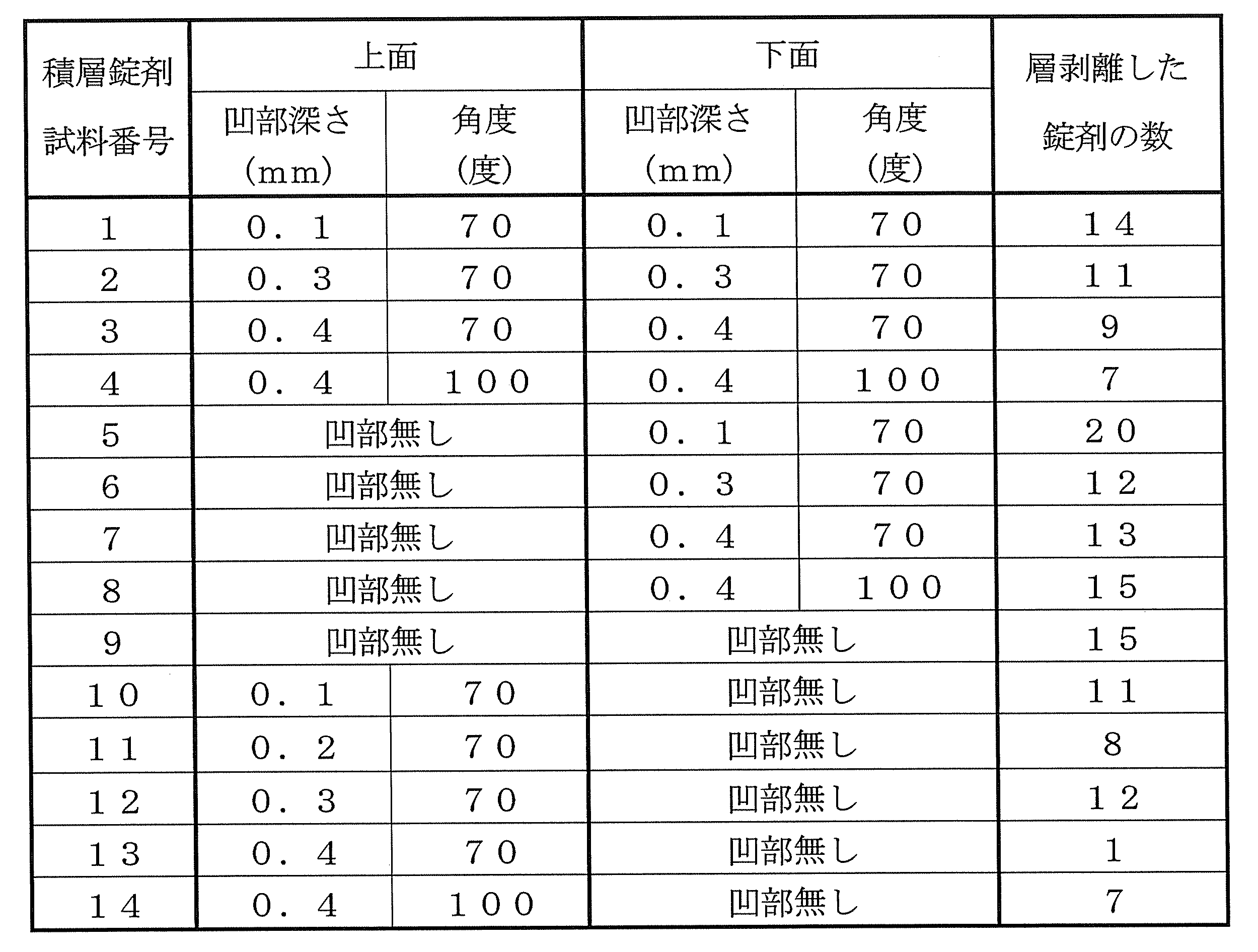
また、両面に凹部を設けなかった試料番号9と、凹部の深さを変えた試料番号(1~3)、(5~7)、(10、11、13)の結果から、凹部が深くなるほど層剥離を抑制する効果が高くなる傾向があることが明らかになった。
また、両面に凹部を設けなかった試料番号9と、凹部のV字の内側の角度を変えた試料番号(3、4)、(7、8)、(13、14)の結果から、V字の内側の角度が70度と100度では、層剥離の抑制効果に顕著な差異がないことがわかった。 In Table 2, comparison is made between
Further, from the results of the
Moreover, from the result of
下記式1中のアログリプチン安息香酸塩(4a)の製造例を以下に示す。 Reference example 1
A production example of alogliptin benzoate (4a) in the following
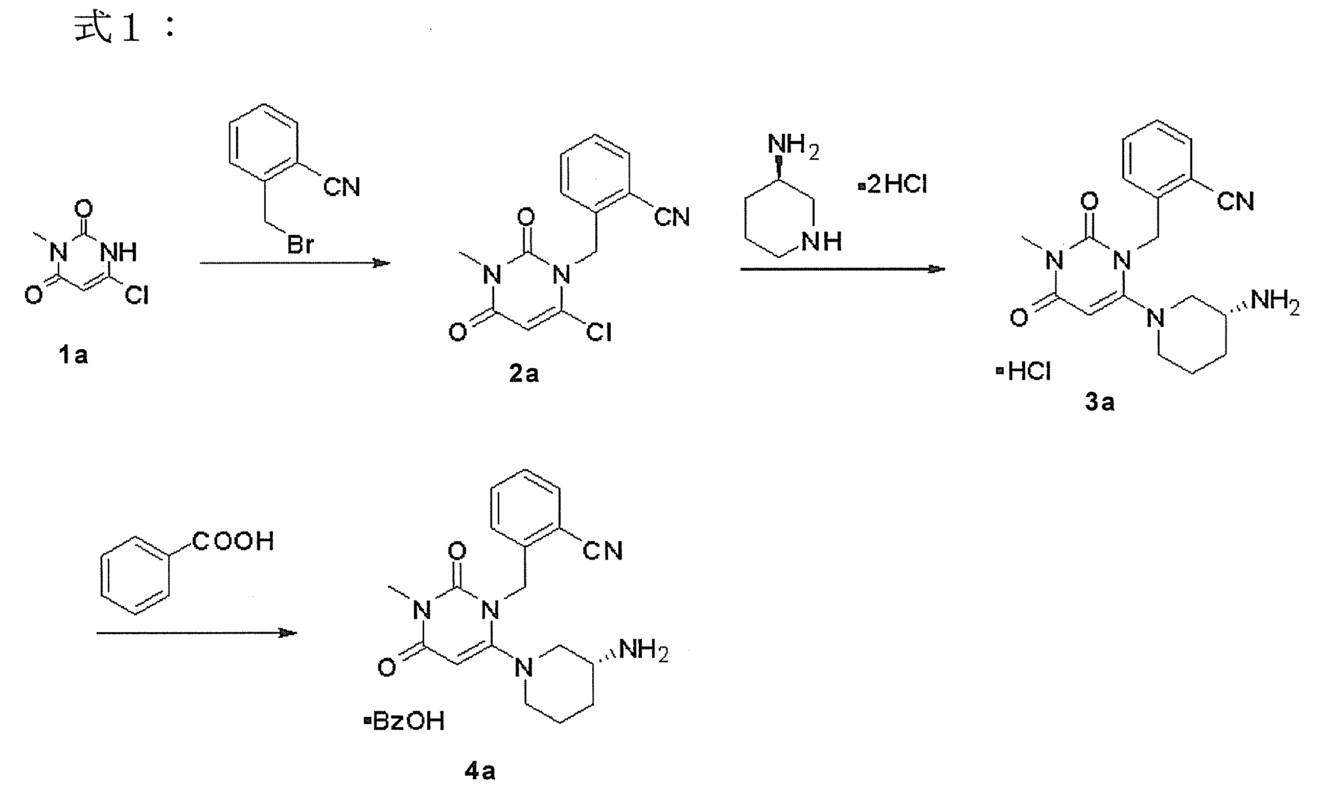
トルエン(1.7倍量)、α-ブロモトルオイルニトリル(1.1当量、1.34wt.)、6-クロロ-3-メチルウラシル(1a)(1当量、1wt.)、N-メチルピロリドン(NMP;3倍量)を内温45~55℃に加熱した。内温45~55℃を保ちながら、ジイソプロピルエチルアミン(ヒューニッヒ塩基、1.5当量、1.21wt.)を加えた。
この混合物を45~55℃で3~7時間または反応終了まで攪拌した。
次いで該溶液を25~35℃に冷却し、25~35℃を保ちながらイソプロパノール(5.8倍量、4.6wt.)を加えた。内温を25~35℃に保ちながら水(4倍量)を加え、約30分間攪拌した。0~5℃に冷却し、その後少なくとも1時間攪拌した。得られたスラリーを濾過し、0~5℃に冷却したイソプロパノール(4.4倍量、3.5wt.)で洗浄し、60℃以下で真空乾燥し、上記化合物(2a)を得た。 [Production Process of 2-((6-Chloro-3-methyl-2,4-dioxo-3,4-dihydropyrimidin-1 (2H) -yl) methyl) benzonitrile (2a) in Formula 1]
Toluene (1.7 times amount), α-bromotoluoylnitrile (1.1 equivalent, 1.34 wt.), 6-chloro-3-methyluracil (1a) (1 equivalent, 1 wt.), N-methylpyrrolidone (NMP; 3 times the amount) was heated to an internal temperature of 45 to 55 ° C. Diisopropylethylamine (Hunig base, 1.5 equivalents, 1.21 wt.) Was added while maintaining the internal temperature at 45 to 55 ° C.
The mixture was stirred at 45-55 ° C. for 3-7 hours or until the end of the reaction.
Next, the solution was cooled to 25 to 35 ° C., and isopropanol (5.8 times volume, 4.6 wt.) Was added while maintaining 25 to 35 ° C. Water (4 times amount) was added while maintaining the internal temperature at 25 to 35 ° C., and the mixture was stirred for about 30 minutes. Cool to 0-5 ° C. and then stir for at least 1 hour. The obtained slurry was filtered, washed with isopropanol (4.4 times amount, 3.5 wt.) Cooled to 0 to 5 ° C., and vacuum-dried at 60 ° C. or lower to obtain the compound (2a).
上記化合物(2a)を、イソプロパノールおよび水中で、1.1当量の(R)-3-アミノピペリジン二塩酸塩と、58~68℃で反応終了まで(例、8~17時間)反応させた。58~68℃を維持している間(約2~5時間に亘り)炭酸カリウム(2当量)を分割して加えた。45~55℃に冷却後、約2~5時間攪拌した。該無機塩を濾過により除去し、濾過ケーキを、熱した(例、45~55℃)イソプロパノールで洗浄した。THFを加え、内温10~20℃に保ちながら35%塩酸で酸性化した。得られたスラリーを0~5℃に冷却し、結晶が成長するまで攪拌し(例えば、1時間以上)、その後濾過した。濾過ケーキをイソプロパノール(6倍量)で洗浄し、上記化合物(3a)のHCl塩が白色結晶性固体として得られるまで乾燥した。 [In the
The above compound (2a) was reacted with 1.1 equivalents of (R) -3-aminopiperidine dihydrochloride in isopropanol and water at 58-68 ° C. until completion of the reaction (eg, 8-17 hours). Potassium carbonate (2 equivalents) was added in portions while maintaining 58-68 ° C. (over about 2-5 hours). After cooling to 45 to 55 ° C., the mixture was stirred for about 2 to 5 hours. The inorganic salt was removed by filtration and the filter cake was washed with hot (eg, 45-55 ° C.) isopropanol. THF was added and acidified with 35% hydrochloric acid while maintaining the internal temperature at 10 to 20 ° C. The resulting slurry was cooled to 0-5 ° C., stirred until crystals grew (eg, over 1 hour), and then filtered. The filter cake was washed with isopropanol (6 volumes) and dried until the HCl salt of compound (3a) was obtained as a white crystalline solid.
上記化合物(3a)の該HCl塩を、35~45℃で水に溶解し、酢酸イソプロピルで洗浄して、二量体を除去した。得られる水相に酢酸イソプロピルを加え45~55℃に加熱し、45~55℃にバッチ温度を維持しながら、固体炭酸カリウムを加えることにより水相から有機相に塩基を遊離させた。55~65℃で各相を分離し、有機相を23%塩化ナトリウム水溶液で洗浄して、残余カリウム塩を除去した。該有機溶媒を減圧下、約3倍に濃縮した。アルコール(4倍量)を加えて、該溶液を減圧下、約4倍まで濃縮した。もう一度4倍量のアルコールを加えて、該溶液を減圧下、約4倍まで再度濃縮した。得られる溶液を除塵フィルターを通すことによって、沈殿した塩化ナトリウムおよび微粒子を除去した。安息香酸の熱エタノール溶液(65~70℃)を加え、該溶液を65~70℃に維持した。次いで該溶液を0~5℃に冷却し、1時間以上攪拌することにより結晶を得た。該溶液を濾過し、アルコールで洗浄した。その後、湿ったケーキを40~50℃で乾燥し、上記化合物(3a)の安息香酸塩(アログリプチン安息香酸塩)(4a)を白色結晶性固体として得た。 [Production Process of Benzoate (4a) of Compound (3a) in Formula 1]
The HCl salt of compound (3a) was dissolved in water at 35-45 ° C. and washed with isopropyl acetate to remove the dimer. To the resulting aqueous phase was added isopropyl acetate and heated to 45-55 ° C., while maintaining the batch temperature at 45-55 ° C., solid potassium carbonate was added to liberate the base from the aqueous phase to the organic phase. The phases were separated at 55-65 ° C. and the organic phase was washed with a 23% aqueous sodium chloride solution to remove residual potassium salts. The organic solvent was concentrated about 3 times under reduced pressure. Alcohol (4 volumes) was added and the solution was concentrated to about 4 times under reduced pressure. Once again 4 times the amount of alcohol was added and the solution was concentrated again to about 4 times under reduced pressure. The resulting solution was passed through a dust filter to remove precipitated sodium chloride and fine particles. A hot ethanolic solution of benzoic acid (65-70 ° C.) was added and the solution was maintained at 65-70 ° C. Next, the solution was cooled to 0 to 5 ° C. and stirred for 1 hour or longer to obtain crystals. The solution was filtered and washed with alcohol. Thereafter, the wet cake was dried at 40 to 50 ° C. to obtain the benzoate (alogliptin benzoate) (4a) of the above compound (3a) as a white crystalline solid.
下記式2中の、2-((6-((3R)-3-アミノピペリジン-1-イル)-3-メチル-2,4-ジオキソ-3,4-ジヒドロピリミジン-1(2H)-イル)メチル)-4-フルオロベンゾニトリル コハク酸塩(4b)の製造例を以下に示す。 Reference example 2
2-((6-((3R) -3-Aminopiperidin-1-yl) -3-methyl-2,4-dioxo-3,4-dihydropyrimidin-1 (2H) -yl in the following formula 2 A production example of) methyl) -4-fluorobenzonitrile succinate (4b) is shown below.

酢酸エチル(3.5倍量)、2-(ブロモメチル)-4-フルオロベンゾニトリル(1b)(1当量、1wt.)、6-クロロ-3-メチルウラシル(1.05当量、0.79wt.)、N-メチルピロリドン(NMP;3.5倍量)、ジイソプロピルエチルアミン(ヒューニッヒ塩基、2.1当量、1.27wt.)を内温60~70℃に加熱した。
この混合物を60~70℃で2~4時間または反応終了まで攪拌した。
次いで該溶液を40~50℃に冷却し、少なくとも30分攪拌後、40~50℃を保ちながらイソプロパノール(1.5倍量)、水(3.5倍量)を加え、その後少なくとも1時間攪拌した。該溶液を20~30℃に冷却し、その後少なくとも1時間攪拌した。該溶液を0~10℃に冷却し、その後少なくとも1時間攪拌した。得られたスラリーを濾過し、0~10℃に冷却したイソプロパノール(4.0倍量)で洗浄し、45~55℃で真空乾燥し、上記化合物(2b)を得た。 [In the
Ethyl acetate (3.5 times amount), 2- (bromomethyl) -4-fluorobenzonitrile (1b) (1 equivalent, 1 wt.), 6-chloro-3-methyluracil (1.05 equivalent, 0.79 wt. ), N-methylpyrrolidone (NMP; 3.5 times the amount) and diisopropylethylamine (Hunig base, 2.1 equivalents, 1.27 wt.) Were heated to an internal temperature of 60 to 70 ° C.
The mixture was stirred at 60-70 ° C. for 2-4 hours or until the end of the reaction.
The solution is then cooled to 40-50 ° C., stirred for at least 30 minutes, and then isopropanol (1.5 times volume) and water (3.5 times volume) are added while maintaining 40-50 ° C., and then stirred for at least 1 hour. did. The solution was cooled to 20-30 ° C. and then stirred for at least 1 hour. The solution was cooled to 0-10 ° C. and then stirred for at least 1 hour. The obtained slurry was filtered, washed with isopropanol (4.0 times amount) cooled to 0 to 10 ° C., and vacuum dried at 45 to 55 ° C. to obtain the above compound (2b).
上記化合物(2b)(1当量、1wt.)、(R)-3-アミノピペリジン二塩酸塩(1.1当量、0.65wt.)、炭酸カリウム(2.5当量、1.18wt.)、イソプロパノール(5.0倍量)、水(1.5倍量)を65~75℃で反応終了まで(例、3~7時間)反応させた。65~75℃で炭酸カリウム(7.05当量、3.32wt.)、水(5.5倍量)を加え、約30分攪拌後、50℃~70℃で各相を分離した。該有機溶媒を減圧下、約5倍に濃縮した。該溶液に水(5倍量)を加えて、減圧下、約5倍まで濃縮した。該溶液を55℃~75℃で約40分攪拌した。該溶液を20℃~30℃に冷却し、その後少なくとも1時間攪拌した。該溶液を0~10℃に冷却し、その後少なくとも1時間攪拌し、得られたスラリーを濾過し、0~10℃に冷却した水(2.0倍量)で洗浄し、45~55℃で真空乾燥し、上記化合物(3b)を得た。 [In the
化合物(3b)、テトラヒドロフラン(6.0倍量)、イソプロパノール(3.0倍量)、水(0.6倍量)を55~65℃に加熱した。コハク酸のテトラヒドロフラン溶液(20℃~30℃)を加え、該溶液を55~65℃に維持し約15分攪拌した。
該溶液を20~30℃に冷却し、少なくとも1時間攪拌した。該溶液を0~10℃に冷却し、その後少なくとも1時間攪拌した。得られたスラリーを濾過後、イソプロパノール(6.0倍量)で洗浄した。得られた湿結晶を65~75℃で乾燥し、上記化合物(3b)のコハク酸塩(4b)を白色結晶性固体として得た。 [Production Process of Succinate (4b) of Compound (3b) in Formula 2]
Compound (3b), tetrahydrofuran (6.0 times amount), isopropanol (3.0 times amount), and water (0.6 times amount) were heated to 55 to 65 ° C. A solution of succinic acid in tetrahydrofuran (20 ° C.-30 ° C.) was added, and the solution was maintained at 55-65 ° C. and stirred for about 15 minutes.
The solution was cooled to 20-30 ° C. and stirred for at least 1 hour. The solution was cooled to 0-10 ° C. and then stirred for at least 1 hour. The resulting slurry was filtered and washed with isopropanol (6.0 times the amount). The obtained wet crystals were dried at 65 to 75 ° C. to obtain the succinate (4b) of the above compound (3b) as a white crystalline solid.
Claims (11)
- 積層錠剤の表裏両面のうちの少なくとも一方の面に、深さ0.1mm以上の凹部が設けられていることを特徴とする、前記積層錠剤。 The laminated tablet, wherein a concave portion having a depth of 0.1 mm or more is provided on at least one of the front and back surfaces of the laminated tablet.
- 上記凹部が形成された一方の面を有する層を最上層として、
該最上層以外の全ての各層が、それら各層の両面のうちの最上層側の面に、上記凹部と同じ形状の凹部を有しており、かつ、それら凹部内には次層の材料が入り込んでいる、請求項1記載の積層錠剤。 As a top layer, a layer having one surface where the concave portion is formed,
All the layers other than the uppermost layer have concave portions having the same shape as the concave portion on the uppermost surface side of both surfaces of the respective layers, and the material of the next layer enters the concave portions. The laminated tablet according to claim 1. - 上記凹部が、1以上の溝状凹部である、請求項1記載の積層錠剤。 The laminated tablet according to claim 1, wherein the recess is one or more groove-like recesses.
- 上記凹部が形成された一方の面を正視したときに、該面の中心点を通過する直線または曲線に沿った溝状凹部が存在している、請求項3記載の積層錠剤。 The laminated tablet according to claim 3, wherein when one surface on which the concave portion is formed is viewed from the front, a groove-shaped concave portion along a straight line or a curve passing through the center point of the surface is present.
- 上記溝状凹部が、上記一方の面の外周縁上の1点から、該面の中心点を通過し、外周縁上の反対側の点まで延びている、請求項4記載の積層錠剤。 The laminated tablet according to claim 4, wherein the groove-shaped recess extends from one point on the outer peripheral edge of the one surface to a point on the opposite side on the outer peripheral edge through the center point of the surface.
- 上記溝状凹部が、V字溝である、請求項5記載の積層錠剤。 The laminated tablet according to claim 5, wherein the groove-shaped recess is a V-shaped groove.
- 上記V字溝のV字の内側の角度が40度~110度である、請求項6記載の積層錠剤。 The laminated tablet according to claim 6, wherein the angle inside the V-shape of the V-groove is 40 to 110 degrees.
- 打錠工程で用いられる一対の杵のうち、上記一方の面を加圧する杵である上杵には、その型面に、上記凹部を形成するための高さ0.1mm以上の凸部が設けられており、
当該積層錠剤中の全ての層が、順次の打錠の際に、同じ上杵によって直接的な加圧を受けており、それによって、上記最上層以外の全ての各層の両面のうちの最上層側の面にも、上記一方の面の凹部と同じ形状の凹部が形成され、かつ、それら各層の凹部内には次層の材料が入り込んでいる、請求項2記載の積層錠剤。 Of the pair of scissors used in the tableting process, the upper scissors that are the scissors that pressurize the one surface are provided with convex portions having a height of 0.1 mm or more on the mold surface to form the concave portions. And
All layers in the laminated tablet are directly pressed by the same upper punch during sequential tableting, so that the uppermost layer of both surfaces of all the layers other than the uppermost layer is The laminated tablet according to claim 2, wherein a concave portion having the same shape as the concave portion on the one surface is formed on the side surface, and the material of the next layer enters the concave portion of each layer. - 請求項1記載の積層錠剤の製造方法であって、
下杵の型面上に、前記積層錠剤中の各層を順次積層し、上杵によって打錠する工程を有し、
少なくとも上杵には、その型面に高さ0.1mm以上の凸部が設けられており、
前記打錠する工程は、前記積層錠剤中の全ての層に対して前記上杵によって加圧する工程を有し、
前記加圧する工程によって、全ての層の両面のうち上杵側の面に深さ0.1mm以上の同じ形状の凹部が形成され、かつ、最上層以外の全ての層の凹部内に次層の材料が入り込んだ積層構造が形成されることを特徴とする、
前記製造方法。 A method for producing a laminated tablet according to claim 1,
Each of the layers in the laminated tablet is sequentially laminated on the mold surface of the lower punch, and has a step of tableting with the upper punch,
At least the upper collar is provided with a convex portion having a height of 0.1 mm or more on the mold surface,
The step of tableting includes the step of pressing with the upper punch on all the layers in the laminated tablet,
By the pressurizing step, a concave portion of the same shape having a depth of 0.1 mm or more is formed on the upper side surface of both surfaces of all layers, and the next layer is formed in the concave portions of all layers other than the uppermost layer. It is characterized in that a laminated structure in which the material enters is formed,
The manufacturing method. - 積層錠剤の層剥離を抑制する方法であって、
積層錠剤の表裏両面のうちの少なくとも一方の面に、深さ0.1mm以上の凹部を設けることを特徴とする、層剥離抑制方法。 A method for suppressing delamination of a laminated tablet,
A method for inhibiting delamination, comprising providing a recess having a depth of 0.1 mm or more on at least one of the front and back surfaces of a laminated tablet. - 下杵の型面上に、積層錠剤中の各層を順次積層し、上杵によって打錠し、前記積層錠剤を形成するに際し、
少なくとも上杵に、その型面に高さ0.1mm以上の凸部を設けておき、
前記積層錠剤中の全ての層を前記上杵によって加圧することによって、全ての層の両面のうち上杵側の面に深さ0.1mm以上の同じ形状の凹部を形成し、かつ、最上層以外の全ての層の前記凹部内に次層の材料が入り込んだ積層構造を形成することを特徴とする、
請求項10記載の方法。 On the mold surface of the lower punch, each layer in the laminated tablet is sequentially laminated, and compressed with the upper punch to form the laminated tablet.
At least on the upper collar, a convex part having a height of 0.1 mm or more is provided on the mold surface,
By pressing all the layers in the laminated tablet with the upper punch, concave portions having the same shape with a depth of 0.1 mm or more are formed on the upper flange side surface of both surfaces of the layers, and the uppermost layer Forming a laminated structure in which the material of the next layer enters into the recesses of all layers other than
The method of claim 10.
Priority Applications (3)
| Application Number | Priority Date | Filing Date | Title |
|---|---|---|---|
| EP12752138.3A EP2682110B1 (en) | 2011-03-03 | 2012-03-02 | Laminated tablet and manufacturing method therefor |
| US14/002,451 US9326946B2 (en) | 2011-03-03 | 2012-03-02 | Laminated tablet and manufacturing method therefor |
| JP2013502416A JP5986984B2 (en) | 2011-03-03 | 2012-03-02 | Multilayer tablet, method for producing the same, and method for suppressing delamination |
Applications Claiming Priority (2)
| Application Number | Priority Date | Filing Date | Title |
|---|---|---|---|
| JP2011-046617 | 2011-03-03 | ||
| JP2011046617 | 2011-03-03 |
Publications (1)
| Publication Number | Publication Date |
|---|---|
| WO2012118180A1 true WO2012118180A1 (en) | 2012-09-07 |
Family
ID=46758106
Family Applications (1)
| Application Number | Title | Priority Date | Filing Date |
|---|---|---|---|
| PCT/JP2012/055382 WO2012118180A1 (en) | 2011-03-03 | 2012-03-02 | Laminated tablet and manufacturing method therefor |
Country Status (4)
| Country | Link |
|---|---|
| US (1) | US9326946B2 (en) |
| EP (1) | EP2682110B1 (en) |
| JP (1) | JP5986984B2 (en) |
| WO (1) | WO2012118180A1 (en) |
Cited By (8)
| Publication number | Priority date | Publication date | Assignee | Title |
|---|---|---|---|---|
| WO2013183497A1 (en) * | 2012-06-05 | 2013-12-12 | 武田薬品工業株式会社 | Dry-coated tablet |
| CN103655505A (en) * | 2013-12-23 | 2014-03-26 | 闻晓光 | Pain relieving bilayer controlled-release tablet and preparation method thereof |
| CN103690503A (en) * | 2013-12-23 | 2014-04-02 | 闻晓光 | Preparation method of double-layer tablet |
| CN103690505A (en) * | 2013-12-23 | 2014-04-02 | 闻晓光 | Hypnotic double-layer controlled release tablet and preparation method thereof |
| WO2014120730A2 (en) * | 2013-01-29 | 2014-08-07 | Otc Nutrition Llc | Micronutrient fortification delivery |
| CN104086527A (en) * | 2014-07-03 | 2014-10-08 | 湖南欧亚生物有限公司 | Synthetic method of alogliptin benzoate |
| WO2015096668A1 (en) * | 2013-12-23 | 2015-07-02 | 闻晓光 | Double-layer tablet and preparation method thereof |
| JP2021066742A (en) * | 2021-02-02 | 2021-04-30 | ライオン株式会社 | Laminated tablets |
Families Citing this family (14)
| Publication number | Priority date | Publication date | Assignee | Title |
|---|---|---|---|---|
| WO2016024224A1 (en) * | 2014-08-11 | 2016-02-18 | Sun Pharmaceutical Industries Limited | A process for the preparation of 4-fluoro-2-methylbenzonitrile |
| CN104402832A (en) * | 2014-11-04 | 2015-03-11 | 广东东阳光药业有限公司 | Preparation method for dihydropyrimidine derivative |
| CN108794448B (en) * | 2015-02-11 | 2021-01-26 | 四川科伦药物研究院有限公司 | Preparation method of trelagliptin and salt thereof |
| WO2016178246A1 (en) * | 2015-05-04 | 2016-11-10 | Indoco Remedies Limited | Process for the preparation of alogliptin |
| EP3368010A4 (en) * | 2015-10-26 | 2019-04-10 | Blaesi, Aron H. | Solid dosage form immediate drug release and apparatus and method for manufacture thereof |
| CN105418581A (en) * | 2015-10-26 | 2016-03-23 | 杭州华东医药集团新药研究院有限公司 | Preparation method of trelagliptin succinate |
| US11129798B2 (en) | 2016-08-19 | 2021-09-28 | Aron H. Blaesi | Fibrous dosage form |
| CN105968093B (en) * | 2016-06-29 | 2018-09-28 | 郑州明泽医药科技有限公司 | The preparation method of amber love song Ge Lieting |
| CN106279104B (en) * | 2016-08-16 | 2019-04-26 | 杭州新博思生物医药有限公司 | A kind of process modification method preparing amber love song Ge Lieting |
| CN106366068A (en) * | 2016-08-19 | 2017-02-01 | 杭州新博思生物医药有限公司 | One-pot preparation method of Alogliptin |
| WO2019246503A1 (en) * | 2018-06-22 | 2019-12-26 | Ideaz, Llc | Diphenyl tablets and methods of preparing the same |
| CN110156750A (en) * | 2019-05-13 | 2019-08-23 | 无锡贝塔医药科技有限公司 | Pyrimidine ring14The preparation method of the amber love song Ge Lieting of C flag |
| CN112552281A (en) * | 2020-12-07 | 2021-03-26 | 石家庄市华新药业有限责任公司 | Synthetic process of trelagliptin succinate bulk drug |
| CN112917981A (en) * | 2020-12-28 | 2021-06-08 | 陕西兴盛新材料股份有限公司 | Electrode pressing process adopting force steering pressurization |
Citations (6)
| Publication number | Priority date | Publication date | Assignee | Title |
|---|---|---|---|---|
| JPH08277218A (en) * | 1995-04-04 | 1996-10-22 | Kyowa Hakko Kogyo Co Ltd | Tablet having split groove and punch having protruding part for forming split groove |
| JP2007020929A (en) * | 2005-07-19 | 2007-02-01 | Yamashita Works:Kk | Tableting pestle |
| JP2008500401A (en) * | 2004-05-21 | 2008-01-10 | アキュ−ブレイク テクノロジーズ インコーポレーテッド | Indented pharmaceutical tablet containing multiple segments |
| JP2008208078A (en) * | 2007-02-27 | 2008-09-11 | Takada Seiyaku Kk | Tablet to be scored |
| JP2009541341A (en) * | 2006-06-19 | 2009-11-26 | エーシーシーユー−ブレイク テクノロジーズ,インク. | Segmented drug dosage form |
| WO2010032717A1 (en) * | 2008-09-16 | 2010-03-25 | 武田薬品工業株式会社 | Film-coated scored tablet |
Family Cites Families (11)
| Publication number | Priority date | Publication date | Assignee | Title |
|---|---|---|---|---|
| DE19922578C2 (en) * | 1999-05-17 | 2003-12-24 | Benckiser Nv | Process for the production of a multilayer tablet, in particular detergent tablet, and product which can be produced thereafter |
| WO2005016306A2 (en) * | 2003-08-06 | 2005-02-24 | Alza Corporation | Uniform delivery of topiramate over prolonged period of time with enhanced dispersion formulation |
| US7622137B2 (en) | 2004-05-21 | 2009-11-24 | Accu-Break Technologies, Inc. | Dosage forms contained within a capsule or sachet |
| US7838031B2 (en) * | 2004-05-21 | 2010-11-23 | Lawrence Solomon | Method of administering a partial dose using a segmented pharmaceutical tablet |
| GB2419838A (en) * | 2004-11-03 | 2006-05-10 | Reckitt Benckiser Nv | Making a tablet of three layers |
| AR051950A1 (en) * | 2004-11-10 | 2007-02-21 | Osmotica Pharmaceutical Argent | MULTI-PAD COMPRESSED WITH SEPARATING LAYERS |
| CA2600736A1 (en) | 2005-03-16 | 2006-09-21 | Dr. Reddy's Laboratories Ltd. | Delivery system for multiple drugs |
| EP3205337A1 (en) * | 2005-08-18 | 2017-08-16 | Teijin Pharma Limited | Formulation having accurate dose-dividing function |
| CA2619745A1 (en) | 2005-08-18 | 2007-02-22 | Teijin Pharma Limited | Tablet with multiple drug-containing sections |
| CA2635313C (en) * | 2005-12-29 | 2013-12-31 | Osmotica Corp. | Triple combination release multi-layered tablet |
| JP2008255064A (en) | 2007-04-06 | 2008-10-23 | Takeda Chem Ind Ltd | Sleep disorder-preventing and treating agent |
-
2012
- 2012-03-02 EP EP12752138.3A patent/EP2682110B1/en active Active
- 2012-03-02 US US14/002,451 patent/US9326946B2/en active Active
- 2012-03-02 JP JP2013502416A patent/JP5986984B2/en active Active
- 2012-03-02 WO PCT/JP2012/055382 patent/WO2012118180A1/en active Application Filing
Patent Citations (6)
| Publication number | Priority date | Publication date | Assignee | Title |
|---|---|---|---|---|
| JPH08277218A (en) * | 1995-04-04 | 1996-10-22 | Kyowa Hakko Kogyo Co Ltd | Tablet having split groove and punch having protruding part for forming split groove |
| JP2008500401A (en) * | 2004-05-21 | 2008-01-10 | アキュ−ブレイク テクノロジーズ インコーポレーテッド | Indented pharmaceutical tablet containing multiple segments |
| JP2007020929A (en) * | 2005-07-19 | 2007-02-01 | Yamashita Works:Kk | Tableting pestle |
| JP2009541341A (en) * | 2006-06-19 | 2009-11-26 | エーシーシーユー−ブレイク テクノロジーズ,インク. | Segmented drug dosage form |
| JP2008208078A (en) * | 2007-02-27 | 2008-09-11 | Takada Seiyaku Kk | Tablet to be scored |
| WO2010032717A1 (en) * | 2008-09-16 | 2010-03-25 | 武田薬品工業株式会社 | Film-coated scored tablet |
Cited By (15)
| Publication number | Priority date | Publication date | Assignee | Title |
|---|---|---|---|---|
| WO2013183497A1 (en) * | 2012-06-05 | 2013-12-12 | 武田薬品工業株式会社 | Dry-coated tablet |
| US9693962B2 (en) | 2012-06-05 | 2017-07-04 | Takeda Pharmaceutical Limited | Dry-coated tablet |
| WO2014120730A3 (en) * | 2013-01-29 | 2014-10-30 | Otc Nutrition Llc | Micronutrient fortification delivery |
| WO2014120730A2 (en) * | 2013-01-29 | 2014-08-07 | Otc Nutrition Llc | Micronutrient fortification delivery |
| CN103690505A (en) * | 2013-12-23 | 2014-04-02 | 闻晓光 | Hypnotic double-layer controlled release tablet and preparation method thereof |
| CN103690503A (en) * | 2013-12-23 | 2014-04-02 | 闻晓光 | Preparation method of double-layer tablet |
| WO2015096668A1 (en) * | 2013-12-23 | 2015-07-02 | 闻晓光 | Double-layer tablet and preparation method thereof |
| CN103655505B (en) * | 2013-12-23 | 2016-10-26 | 闻晓光 | A kind of pain relieving class two-layer release-controlled tablet and preparation method thereof |
| CN103655505A (en) * | 2013-12-23 | 2014-03-26 | 闻晓光 | Pain relieving bilayer controlled-release tablet and preparation method thereof |
| US10137092B2 (en) | 2013-12-23 | 2018-11-27 | Xiaoguang WEN | Double-layer tablet and preparation method thereof |
| US10925836B2 (en) | 2013-12-23 | 2021-02-23 | Overseas Pharmaceuticals (Guangzhou) Ltd. | Double-layer tablet and painkiller tablet with same structure |
| US10940114B2 (en) | 2013-12-23 | 2021-03-09 | Overseas Pharmaceuticals (Guangzhou) Ltd. | Hypnotics tablet with double-layer structure |
| CN104086527A (en) * | 2014-07-03 | 2014-10-08 | 湖南欧亚生物有限公司 | Synthetic method of alogliptin benzoate |
| JP2021066742A (en) * | 2021-02-02 | 2021-04-30 | ライオン株式会社 | Laminated tablets |
| JP7098008B2 (en) | 2021-02-02 | 2022-07-08 | ライオン株式会社 | Laminated tablets and their manufacturing methods |
Also Published As
| Publication number | Publication date |
|---|---|
| EP2682110A4 (en) | 2014-11-05 |
| JP5986984B2 (en) | 2016-09-06 |
| US20140023708A1 (en) | 2014-01-23 |
| JPWO2012118180A1 (en) | 2014-07-07 |
| EP2682110A1 (en) | 2014-01-08 |
| US9326946B2 (en) | 2016-05-03 |
| EP2682110B1 (en) | 2019-12-04 |
Similar Documents
| Publication | Publication Date | Title |
|---|---|---|
| JP5986984B2 (en) | Multilayer tablet, method for producing the same, and method for suppressing delamination | |
| JP5509086B2 (en) | Film-coated scored tablets | |
| TWI396561B (en) | Dividable galenical form allowing modified release of the active ingredient | |
| CN108601741B (en) | Galenic formulations of organic compounds | |
| US20210093577A1 (en) | Enteric coated tablet | |
| US20130183384A1 (en) | Immediate release multi unit pellet system | |
| EP2554159A1 (en) | Dosage forms comprising apixaban and content uniformity enhancer | |
| MXPA03010430A (en) | Tablet comprising cetirizine and pseudoephedrine. | |
| CN107530337B (en) | Method of treatment | |
| EP2612657A1 (en) | Orally disintegrating tablet | |
| HRP20031057A2 (en) | Tablet comprising cetirizine and pseudoephedrine | |
| US8968779B2 (en) | Controlled release coat-core tablet | |
| WO2014096277A1 (en) | Tablet composition comprising cinacalcet hydrochloride | |
| WO2013089489A1 (en) | Orally disintegrating tablet, and method for preparing same | |
| KR20170134409A (en) | Tree pulse release stimulant formulation | |
| JP2011173848A (en) | Tablet quickly disintegrable in oral cavity | |
| US20180169021A1 (en) | Ranolazine multiple compressed tablets | |
| US10548848B2 (en) | Alogliptin formulation | |
| JP2011213695A (en) | Donepezil hydrochloride-containing tablet quickly disintegrable in oral cavity | |
| WO2019018158A1 (en) | Pharmaceutical compositions | |
| JP5886530B2 (en) | tablet | |
| EP2934485B1 (en) | Tablet composition comprising cinacalcet hydrochloride | |
| RU2412706C1 (en) | Modified release dosage form of trimetazidine dihydrochloride | |
| RU2773029C2 (en) | Galenic compositions of organic compounds | |
| CN109996537A (en) | Tablets for oral use composition comprising R-lansoprazole, the tablets for oral use comprising the composition and its manufacturing method |
Legal Events
| Date | Code | Title | Description |
|---|---|---|---|
| 121 | Ep: the epo has been informed by wipo that ep was designated in this application |
Ref document number: 12752138 Country of ref document: EP Kind code of ref document: A1 |
|
| ENP | Entry into the national phase |
Ref document number: 2013502416 Country of ref document: JP Kind code of ref document: A |
|
| WWE | Wipo information: entry into national phase |
Ref document number: 2012752138 Country of ref document: EP |
|
| NENP | Non-entry into the national phase |
Ref country code: DE |
|
| WWE | Wipo information: entry into national phase |
Ref document number: 14002451 Country of ref document: US |