WO2012117750A1 - Control device for construction machine - Google Patents
Control device for construction machine Download PDFInfo
- Publication number
- WO2012117750A1 WO2012117750A1 PCT/JP2012/050125 JP2012050125W WO2012117750A1 WO 2012117750 A1 WO2012117750 A1 WO 2012117750A1 JP 2012050125 W JP2012050125 W JP 2012050125W WO 2012117750 A1 WO2012117750 A1 WO 2012117750A1
- Authority
- WO
- WIPO (PCT)
- Prior art keywords
- engine
- output
- rotational speed
- assist
- upper limit
- Prior art date
Links
Images


Classifications
-
- E—FIXED CONSTRUCTIONS
- E02—HYDRAULIC ENGINEERING; FOUNDATIONS; SOIL SHIFTING
- E02F—DREDGING; SOIL-SHIFTING
- E02F9/00—Component parts of dredgers or soil-shifting machines, not restricted to one of the kinds covered by groups E02F3/00 - E02F7/00
- E02F9/20—Drives; Control devices
- E02F9/22—Hydraulic or pneumatic drives
-
- F—MECHANICAL ENGINEERING; LIGHTING; HEATING; WEAPONS; BLASTING
- F02—COMBUSTION ENGINES; HOT-GAS OR COMBUSTION-PRODUCT ENGINE PLANTS
- F02D—CONTROLLING COMBUSTION ENGINES
- F02D29/00—Controlling engines, such controlling being peculiar to the devices driven thereby, the devices being other than parts or accessories essential to engine operation, e.g. controlling of engines by signals external thereto
- F02D29/04—Controlling engines, such controlling being peculiar to the devices driven thereby, the devices being other than parts or accessories essential to engine operation, e.g. controlling of engines by signals external thereto peculiar to engines driving pumps
-
- E—FIXED CONSTRUCTIONS
- E02—HYDRAULIC ENGINEERING; FOUNDATIONS; SOIL SHIFTING
- E02F—DREDGING; SOIL-SHIFTING
- E02F9/00—Component parts of dredgers or soil-shifting machines, not restricted to one of the kinds covered by groups E02F3/00 - E02F7/00
- E02F9/20—Drives; Control devices
-
- E—FIXED CONSTRUCTIONS
- E02—HYDRAULIC ENGINEERING; FOUNDATIONS; SOIL SHIFTING
- E02F—DREDGING; SOIL-SHIFTING
- E02F9/00—Component parts of dredgers or soil-shifting machines, not restricted to one of the kinds covered by groups E02F3/00 - E02F7/00
- E02F9/20—Drives; Control devices
- E02F9/2058—Electric or electro-mechanical or mechanical control devices of vehicle sub-units
- E02F9/2062—Control of propulsion units
- E02F9/2066—Control of propulsion units of the type combustion engines
-
- E—FIXED CONSTRUCTIONS
- E02—HYDRAULIC ENGINEERING; FOUNDATIONS; SOIL SHIFTING
- E02F—DREDGING; SOIL-SHIFTING
- E02F9/00—Component parts of dredgers or soil-shifting machines, not restricted to one of the kinds covered by groups E02F3/00 - E02F7/00
- E02F9/20—Drives; Control devices
- E02F9/2058—Electric or electro-mechanical or mechanical control devices of vehicle sub-units
- E02F9/2062—Control of propulsion units
- E02F9/2075—Control of propulsion units of the hybrid type
-
- E—FIXED CONSTRUCTIONS
- E02—HYDRAULIC ENGINEERING; FOUNDATIONS; SOIL SHIFTING
- E02F—DREDGING; SOIL-SHIFTING
- E02F9/00—Component parts of dredgers or soil-shifting machines, not restricted to one of the kinds covered by groups E02F3/00 - E02F7/00
- E02F9/20—Drives; Control devices
- E02F9/22—Hydraulic or pneumatic drives
- E02F9/2221—Control of flow rate; Load sensing arrangements
- E02F9/2232—Control of flow rate; Load sensing arrangements using one or more variable displacement pumps
- E02F9/2235—Control of flow rate; Load sensing arrangements using one or more variable displacement pumps including an electronic controller
-
- E—FIXED CONSTRUCTIONS
- E02—HYDRAULIC ENGINEERING; FOUNDATIONS; SOIL SHIFTING
- E02F—DREDGING; SOIL-SHIFTING
- E02F9/00—Component parts of dredgers or soil-shifting machines, not restricted to one of the kinds covered by groups E02F3/00 - E02F7/00
- E02F9/20—Drives; Control devices
- E02F9/22—Hydraulic or pneumatic drives
- E02F9/2246—Control of prime movers, e.g. depending on the hydraulic load of work tools
Definitions
- the present invention relates to a hybrid construction machine including a hydraulic actuator such as a hydraulic excavator or a wheel loader, and more particularly to a control device thereof.
- Construction machines such as hydraulic excavators driven by a hydraulic system often have a large engine that is selected for work at maximum load so that it can handle all work from light loads to heavy loads. .
- the work that causes heavy loads in the entire work of the construction machine (for example, during heavy excavation work in which excavation and loading of earth and sand is frequently performed in a hydraulic excavator) is only a part.
- the engine capacity is surplus at light load and medium load (for example, light excavation work that performs leveling work to level the ground in a hydraulic excavator), fuel consumption (hereinafter abbreviated as fuel consumption)
- fuel consumption fuel consumption
- a hybrid construction machine is known in which an engine is downsized to reduce fuel consumption, and an output shortage due to the downsizing of the engine is assisted by output from an electric motor / generator.
- a determination unit that determines whether or not generation is necessary, and when the determination unit determines that generation of an assist output is unnecessary, a maximum torque line indicating a maximum absorption torque that can be absorbed by the hydraulic pump; If the first maximum torque line that increases the maximum absorption torque with the increase in the engine target speed is selected, and the determination means determines that the generation of the assist output is necessary, the maximum torque line is The second maximum torque line is selected in which the maximum absorption torque is larger in the engine low speed region than the first maximum torque line.
- the above technology is examined from this viewpoint.
- the maximum absorption torque of the hydraulic pump is uniquely determined according to the engine speed, and when assisting the engine with an electric motor / generator, the maximum absorption torque is set in the low speed range in other cases. The value is larger than. For this reason, when a large load is applied to the work device while the engine is operating in the low rotation speed region, naturally, a large load is also applied to the engine. Therefore, if engine torque assist by the motor / generator is insufficient or delayed, there may be a lag down in which the engine speed drops, or an engine stall may occur. The occurrence of lag down leads to deterioration of exhaust gas conditions such as generation of black smoke due to rapid fuel injection to return the engine speed to the target speed and fuel consumption. In addition, the change in engine sound accompanying the decrease in engine speed makes the operator uncomfortable.
- the present invention has been made to solve such problems, and is a power-saving and fuel-efficient control device for a hybrid construction machine that suppresses transient assist output by an electric motor / generator when the engine is accelerated.
- the purpose is to provide.
- the present invention includes an engine, a variable displacement hydraulic pump driven by the engine, a hydraulic actuator driven by pressure oil discharged from the hydraulic pump, and the engine.
- a construction machine comprising: an electric motor / generator for transmitting torque between the electric motor / electric generator; an electric storage means for supplying electric power to the electric motor / generator; and a pump capacity adjusting means for adjusting the capacity of the hydraulic pump based on an operation signal.
- an actual rotational speed detecting means for detecting the actual rotational speed of the engine, a target rotational speed setting means for determining a target rotational speed of the engine, a load detecting means for detecting a load of the hydraulic pump, and the actual rotational speed Rotational speed deviation which is the difference between the actual rotational speed input from the rotational speed detection means and the target rotational speed input from the target rotational speed setting means, or the load detection
- the means reduces the absorption torque upper limit value of the hydraulic pump from the calculated value when the rotation speed deviation is equal to or larger than a set value set according
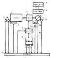
- FIG. 1 is a schematic diagram of a hydraulic drive control device for a hybrid hydraulic excavator according to an embodiment of the present invention.
- the control characteristic figure of the pump absorption torque by the regulator 14 which concerns on embodiment of this invention.
- the schematic block diagram of the controller 8 in embodiment of this invention.
- the schematic block diagram of the assist output calculating part 19 in embodiment of this invention.
- the figure which shows the relationship between the setting value NC of rotation speed deviation and assist output in this Embodiment.
- size of rotation speed deviation (DELTA) N An example of construction machine control when the load of the hydraulic pump 3 gradually becomes heavy and the assist output increases from the situation where the engine 1 is operating at the target rotational speed without the assist output.
- the torque diagram corresponding to the time t2 in FIG. The torque diagram corresponding to the time t3 in FIG.
- the torque diagram corresponding to the time t1 in FIG. The torque diagram corresponding to the time t2 in FIG.
- the torque diagram corresponding to the time t3 in FIG. The figure which shows the relationship between the setting value NC of rotation speed deviation and the electrical storage amount of the electrical storage apparatus 10 in this Embodiment.
- FIG. 1 is a schematic diagram of a hydraulic drive control device for a hybrid hydraulic excavator according to an embodiment of the present invention.
- the hydraulic drive control device shown in this figure includes an engine 1, a governor 7 that adjusts the fuel injection amount of the engine 1, a rotation speed sensor (actual rotation speed detection means) 16 that detects the actual rotation speed of the engine 1, an engine 1, an engine torque sensor (engine torque detecting means) 31 for detecting the torque of 1, a variable displacement hydraulic pump 3 driven by the engine 1 (hereinafter simply referred to as “hydraulic pump 3”), and a hydraulic pump 3
- a hydraulic actuator 5 driven by pressure oil discharged from the motor, a motor / generator 2 that is arranged on the drive shaft of the engine 1 and transmits torque to / from the engine 1, and power to the motor / generator 2 It is necessary to control the number of revolutions of the power storage device (power storage means) 10 to be supplied, the pump capacity adjustment device (pump capacity adjustment means) 45 for adjusting
- the inverter (electric motor / generator control means) 9 for transferring power to and from the power storage device 10 and the governor 7 to adjust the fuel injection amount to control the engine speed and to control the inverter 9 for electric
- a controller (control device) 8 that controls the torque of the generator 2 is provided.
- the hydraulic drive control device shown in FIG. 1 first supplies the pressure oil discharged by the hydraulic pump 3 to a valve device 4 having a plurality of control valves, and the flow rate, direction, and pressure of the pressure oil are appropriately changed by the valve device 4.
- the drive of each hydraulic actuator 5 is controlled by supplying each hydraulic actuator 5 later.
- the hydraulic actuator 5 installed in the hydraulic excavator according to the present embodiment includes a hydraulic cylinder (boom cylinder, arm cylinder, and bucket cylinder) for driving an articulated front working device attached in front of the upper swing body. Etc.), a hydraulic motor (swing motor) for turning the upper turning body, a hydraulic motor (traveling motor) for running the lower traveling body attached to the lower part of the upper turning body, etc. These are collectively referred to as a hydraulic actuator 5.
- the engine 1 is regulated by controlling the fuel injection amount by the governor 7.
- the hydraulic pump 3 includes a discharge pressure sensor that measures the pressure of the pressure oil discharged from the hydraulic pump 3 as means (pump information detection means 21) for detecting information necessary for calculating the load of the hydraulic pump 3.
- a flow meter for measuring the flow rate of the pressure oil and a tilt angle sensor for measuring the tilt angle of the hydraulic pump 3 are installed.
- the discharge pressure sensor, the flow meter, and the tilt angle sensor are provided in the controller 8.
- the detected sensor value is output.
- a pump load calculation unit 26 (described later) in the controller 8 calculates the load of the hydraulic pump 3 based on each sensor value input from the pump information detection means 21.
- the pump capacity adjusting device 45 adjusts the capacity of the hydraulic pump 3 based on an operation signal output from the controller 8 and includes a regulator 14 and an electromagnetic proportional valve 15.
- the regulator 14 is provided in the hydraulic pump 3, and when the tilt angle of the swash plate or the oblique shaft of the hydraulic pump 3 is operated by the regulator 14, the capacity (displacement volume) of the hydraulic pump 3 is changed and absorption of the hydraulic pump 3 is performed. Torque (input torque) can be controlled (pump absorption torque control).
- the regulator 14 in this embodiment is controlled by the control pressure generated by the electromagnetic proportional valve 15.
- the electromagnetic proportional valve 15 operates based on a command value output from an operation signal generation unit 24 (described later) in the controller 8.
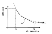
- the regulator 14 controls the capacity of the hydraulic pump 3 according to the control characteristic diagram shown in FIG. FIG. 2 is a control characteristic diagram of pump absorption torque by the regulator 14 according to the embodiment of the present invention.
- a broken line 2A shown in this figure indicates the characteristic of the capacity of the hydraulic pump 3 set with respect to the discharge pressure of the hydraulic pump 3, and the maximum value of the total output of the engine 1 and the motor / generator 2 (in FIG. 2).
- the torque (product of pump capacity and pump discharge pressure) of the hydraulic pump 3 is set to be substantially constant within a range not exceeding the hyperbola (constant torque diagram) indicated by the broken line.
- the torque of the hydraulic pump 3 is controlled so as not to exceed the maximum output by the engine 1 and the motor / generator 2. it can.
- the pump discharge pressure is P1 or less
- the pump absorption torque control is not performed, and the pump capacity is determined by the operation amount of the operation lever for operating each control valve of the valve device 4 (for example, any one of the operation levers) Q1 when the operation amount is maximum).
- the pump discharge pressure becomes P1 to P2
- pump absorption torque control is performed by the regulator 14, and the pump tilt angle is adjusted by the regulator 14 so that the pump capacity decreases along the broken line 2A as the pump discharge pressure increases. Is operated.
- the pump absorption torque is controlled to be equal to or less than the torque defined by the broken line 2A.
- P2 is the maximum value of the pump discharge pressure, which is equal to the set pressure of the relief valve connected to the circuit on the hydraulic pump 3 side in the valve device 2, and the pump discharge pressure does not increase above this value.
- a polygonal line 2A that combines two straight lines is used as a control characteristic diagram of the absorption torque of the hydraulic pump, but other values can be set as long as they do not exceed the constant torque diagram (hyperbola) in FIG.
- a control characteristic diagram may be used.
- the controller 8 outputs an operation signal (electrical signal) generated based on the absorption torque of the hydraulic pump 3 to the electromagnetic proportional valve 15, and the electromagnetic proportional valve 15 generates a control pressure corresponding to the operation signal to thereby generate a regulator 14. Drive.
- the capacity of the hydraulic pump 3 is changed by the regulator 14, and the absorption torque of the hydraulic pump 3 is adjusted to a range in which engine stall does not occur.
- the power storage device 10 constituted by a battery, a capacitor, or the like includes a current sensor 11, a voltage sensor 12, and a temperature as means (power storage information detection means 22) for detecting information necessary for calculating the amount of power stored in the power storage device 10.
- a sensor 13 is attached. Based on information such as current, voltage, and temperature detected by these sensors 11, 12, and 13, the controller 8 calculates the amount of power stored in the power storage device 10 in a power storage amount calculation unit 25 (described later). Manage the amount.
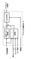
- FIG. 3 is a schematic configuration diagram of the controller 8 according to the embodiment of the present invention.
- the controller 8 shown in this figure calculates the command values for the engine 1, the motor / generator 2 and the hydraulic pump 3, and includes a target rotational speed setting unit (target rotational speed setting means) 17 and an engine maximum output.
- the controller 8 includes an engine actual speed detected by a speed sensor (actual speed detecting means) 16, an engine torque detected by an engine torque sensor (engine torque detecting means) 31, and a storage information detecting means 22.
- the detected power storage information current, voltage and temperature of the power storage device 10
- the pump information detected by the pump information detection means 21 pressure and pressure of hydraulic oil and the tilt angle of the hydraulic pump 3
- the hydraulic excavator A target engine speed input from a target speed input device 29 (for example, an engine control dial) installed in the cab (cab) and to which a desired target engine speed is input by an operator is input.
- a target speed input device 29 for example, an engine control dial
- the power storage amount calculation unit 25 is a portion that calculates the power storage amount of the power storage device 10 based on the power storage information input from the current sensor 11, the voltage sensor 12, and the temperature sensor 13 (power storage information detection means 22).
- a storage amount detection unit 27 is configured together with the means 22.
- the storage amount calculated by the storage amount calculation unit 25 is output to the assist output calculation unit 19 and the absorption torque upper limit calculation unit 22.
- the pump load calculation unit 26 is a part that calculates the load of the hydraulic pump 3 based on the pump information input from the discharge pressure sensor, the flow meter, and the tilt angle sensor (pump information detection means 21). 21 constitutes a pump load detection unit 28.
- the pump load calculated by the pump load calculation unit 26 is output to the assist output calculation unit 19.
- the engine output calculation unit 32 is a part that calculates the actual output of the engine 1 based on the engine torque input from the engine torque sensor 31.
- the engine output detection unit (engine output detection means) 20 is operated together with the engine torque sensor 31. It is composed.
- the output calculated by the engine output calculation unit 32 is output to the assist output calculation unit 19.
- the target rotational speed setting unit 17 is a part that determines the target rotational speed of the engine 1 so that an engine output corresponding to the load of the hydraulic pump 3 (the load state of the hydraulic actuator 5) calculated by the pump load calculating unit 26 is secured.
- the target rotational speed is determined in preference to the target rotational speed input from the target rotational speed input device 29. At this time, from the viewpoint of reducing the fuel consumption in the engine 1, it is preferable to set the operating point at which the fuel consumption relative to the required output of the engine 1 is the minimum as the target rotational speed command value of the engine 1.
- the target rotational speed determined by the target rotational speed setting unit 17 is output to the absorption torque upper limit calculation unit 23 and the operation signal generation unit 24.
- the target rotational speed is output to the assist output calculation unit 19 as a deviation from the actual rotational speed detected by the rotational speed sensor 16.
- the target rotational speed determined here is also used for control of the generator / motor 2, but once the engine 1 and the motor / generator 2 are connected via a speed reducer, etc.
- a value obtained by multiplying the target rotational speed by the reduction ratio of the reduction gear may be separately defined and used as the target rotational speed.
- the engine maximum output calculation unit 18 is based on the actual engine speed input from the engine speed sensor 16 and a table set in accordance with engine characteristics and stored in a storage device (ROM or the like). Thus, the maximum output that the engine 1 can output is calculated. The maximum output calculated by the engine maximum output calculation unit 18 is output to the assist output calculation unit 19.
- the assist output calculation unit 19 performs both acceleration assist for quickly accelerating the engine 1 to the target rotational speed determined by the target rotational speed setting unit 17 and power assist for compensating for an insufficient output of the engine alone. This is a part for calculating a motor torque command value (assist output command value) to be output by the motor / generator 2 in order to realize the above.
- the assist output calculation unit 19 is a rotation speed deviation ⁇ N that is a difference between the actual rotation speed input from the rotation speed sensor 16 and the target rotation speed input from the target rotation speed setting section 17, or a pump Based on the load of the hydraulic pump 3 input from the load detector 28, the assist output (engine assist output) generated by the motor / generator 2 is calculated.
- FIG. 4 is a schematic configuration diagram of the assist output calculation unit 19 in the embodiment of the present invention.
- the assist output calculation unit 19 shown in this figure includes an acceleration assist calculation unit 41, a power assist calculation unit 42, and an output determination unit 43.
- the acceleration assist calculation unit 41 assists the output of the motor / generator 2 (acceleration assist output) when assisting the output of the engine 1 in order to quickly accelerate the actual rotational speed of the engine 1 to the target rotational speed (during acceleration assist). ), And the acceleration assist calculation unit 41 is input with a rotation speed deviation ⁇ N that is the difference between the target rotation speed of the engine 1 and the actual rotation speed.
- the assist output is calculated based on the rotational speed deviation ⁇ N that is the difference between the target rotational speed of the engine 1 and the actual rotational speed, and becomes smaller as the rotational speed deviation ⁇ N approaches zero.
- the power assist calculation unit 42 assists the motor / generator 2 when the assist by the motor / generator 2 is necessary because the output is insufficient only by the output of the engine 1 (during power assist) (power assist output).
- the rotational speed deviation ⁇ N, the maximum engine output, the engine output, and the pump load are input.
- the assist output is based on the difference between the load of the hydraulic pump 3 input from the pump load calculation unit 26 and the engine output input from the engine output calculation unit 32 (engine output detection unit 20). Is calculated. In this calculation, referring to the engine maximum output input from the engine maximum output calculation unit 18, the minimum value of the power assist output that can be required at the actual rotational speed of the engine 1 at that time can be calculated.
- the power assist calculation unit 42 preferably calculates an assist output using feedforward input or integral control. .
- the difference in output is calculated as an assist output to be generated by the motor / generator 2.
- the output determination unit 43 is a part that adds the assist outputs calculated by the acceleration assist calculation unit 41 and the power assist calculation unit 42 and generates a motor torque command value corresponding to the assist output after the addition. 43, the sum of the assist outputs calculated by the acceleration assist calculation unit 41 and the power assist calculation unit 42 and the storage amount of the power storage device 10 are input.
- the output determination unit 43 when the storage amount of the power storage device 10 input from the storage amount calculation unit 25 is small and cannot generate the assist output calculated by the assist calculation units 41 and 42, the motor / generator 2 The assist output amount is limited, and the motor torque command value corresponding to the limited assist output is calculated.
- the motor / generator 2 has a function of calculating a motor torque command value for generating power.
- the assist output calculation unit 19 calculates the assist output from the motor / generator 2 based on the engine maximum output input from the engine maximum output calculation unit 18 and the engine output input from the engine output detection unit 20. You may do it. In this way, the assist output by the motor / generator can be determined based on the current output of the engine 1 and the maximum output of the engine 1 at the number of rotations thereof. It is possible to avoid wasteful consumption of the power storage amount of the power storage device 10 without performing the assist by the motor / generator 2. In addition, when the engine output reaches the maximum value, the assist is performed immediately, so that the engine stall can be avoided as well as following the engine speed to the target speed with good response. it can.
- the absorption torque upper limit calculation unit 23 is a part that calculates the upper limit value (maximum value) of the absorption torque (input torque) of the hydraulic pump 3, and the absorption torque upper limit value calculated here is used as the operation signal generation unit. 24 is output.
- the absorption torque upper limit calculation unit 33 in the present embodiment normally calculates the pump absorption torque upper limit value according to the control characteristic diagram shown in FIG. However, when the rotational speed deviation ⁇ N is equal to or greater than a set value (hereinafter sometimes referred to as “set value NC”), a value obtained by further reducing the predetermined absorption torque from the value calculated based on the control characteristic diagram of FIG. Is calculated as the pump absorption torque upper limit value.
- set value NC a set value obtained by further reducing the predetermined absorption torque from the value calculated based on the control characteristic diagram of FIG.
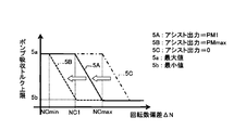
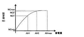
- FIG. 5 is a diagram showing a relationship between the set value NC of the rotational speed deviation and the assist output in the present embodiment.
- the set value NC is set according to the magnitude of the assist output calculated by the assist output calculation unit 19. More specifically, the set value NC shown in this figure takes the maximum value NCmax when the assist output PM is zero, and takes the minimum value NCmin when the assist output PM is maximum. The assist output is set so as to decrease as the assist output increases.
- pump absorption torque control performed by the absorption torque upper limit calculation unit 23 when the rotation speed deviation ⁇ N is equal to or larger than the set value NC will be described with reference to the drawings.
- FIG. 6 is an example of a change in the control characteristic diagram of the pump absorption torque by the regulator 14 when the rotation deviation ⁇ N is equal to or larger than the set value NC.
- the assist output is constant and the set value NC is a constant value
- the rotational speed deviation ⁇ N changes from a value less than the set value NC to a value greater than the set value NC.
- the polygonal line 7A in the figure corresponds to the polygonal line 2A in FIG.
- the absorption torque upper limit calculation unit 23 forms a broken line according to the magnitude of the deviation between the rotational speed deviation ⁇ N and the set value NC.
- the pump absorption torque upper limit value is reduced so as to transition from 7A to 7B and further from 7B to 7C. If the pump absorption torque upper limit value is reduced in this way, the pump absorption torque can be reduced in accordance with the magnitude of the rotational speed deviation ⁇ N, so that the engine 1 or the motor / generator is adapted to the magnitude of the rotational speed deviation ⁇ N. 2 can be reduced.
- the control characteristic (broken line) may be changed stepwise (for example, three steps 7A, 7B, and 7C shown in FIG. 7) according to the magnitude of the deviation between the rotational speed deviation ⁇ N and the set value NC. Then, the transition may be made gradually from the broken line 7A to the broken line 7C according to the magnitude of the deviation between the rotational speed deviation ⁇ N and the set value NC. If the latter control characteristic is used, since it is possible to suppress the pump absorption torque upper limit from changing suddenly, it is possible to suppress the deterioration of the operability of the front work device compared to the former case. In addition, since the parameter for changing the line of control characteristics can be defined by a function, it is not necessary to prepare many data tables in advance as in the former case. Next, a case where the transition is made gradually from the broken line 7A to the broken line 7C in accordance with the magnitude of the deviation between the rotational speed deviation ⁇ N and the set value NC will be described with reference to the drawings.
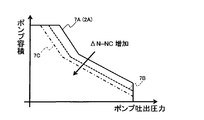
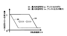
- FIG. 7 is a diagram showing an example of a change in the characteristic diagram of the pump absorption torque upper limit value when the assist output changes in magnitude (that is, when the set value NC changes).
- the reference characteristic diagram which is translated in the horizontal direction (horizontal axis direction) according to the size of the assist output, will be described as a characteristic diagram for each assist output value (in this case, the increase in assist output)
- the characteristic diagram translates to the left as indicated by the arrow in the figure).
- the rotational speed deviation ⁇ N is equal to or less than the set value NC1
- the target value of the engine 1 is not reduced without reducing the pump absorption torque upper limit value, that is, without performing torque reduction control on the absorption torque of the hydraulic pump 3.
- Control using the pump absorption torque upper limit 5a corresponding to the rotational speed is performed (that is, absorption torque control is performed on the broken line 7A in FIG. 6).
- absorption torque control is performed on the broken line 7A in FIG. 6).
- the rotational speed deviation ⁇ N exceeds the set value NC1
- the amount of torque reduction increases according to the rotational speed deviation ⁇ N (that is, the broken line in FIG. 6 moves from 7A to 7C).
- the pump absorption torque upper limit value gradually decreases from the upper limit value 5a toward the lower limit value 5b as the rotational speed deviation ⁇ N increases.
- the reduction amount of the pump absorption torque upper limit value is increased in accordance with the magnitude of the rotational speed deviation ⁇ N, the load on the engine 1 or the motor / generator 2 caused by the hydraulic pump load is increased to the magnitude of the rotational speed deviation ⁇ N. It can be made smaller.
- the pump absorption torque upper limit value is stopped to decrease.
- 5b is the minimum value of the pump absorption torque upper limit value, and the lowering is stopped at this value.
- the minimum value of the pump absorption torque upper limit value is at least necessary in the operation of the front work device from the viewpoint of avoiding the situation where the front work device does not operate at all in response to the operation of the operation lever by the operator. It is preferable to set a pump absorption torque value.
- the minimum value is set as high as possible to the pump absorption torque upper limit value to ensure the quick operation of the front work device, and the output of the engine 1 and the motor / generator 2 and the amount of power stored in the power storage device 10. It is preferable to be able to change sequentially according to the size. That is, the minimum value is preferably increased in accordance with the surplus output of the engine 1 and the motor / generator 2, and is preferably increased in accordance with the amount of power stored in the power storage device 10.
- the load on the engine 1 increases due to an increase in the load on the front working device from the state where the characteristic diagram of the pump absorption torque upper limit value of 5A is used, and electric power is supplied to supplement the output of the engine 1. This corresponds to the case where the assist output by the generator 2 reaches the maximum.
- the pump absorption torque upper limit starts to decrease from the time when the rotational speed deviation ⁇ N reaches the set value NCmin. Therefore, the pump absorption torque upper limit starts to be lower than in the case of 5A (NC1). The value becomes smaller. As a result, it is possible to prevent an overload situation in which the engine speed drops even though the assist by the motor / generator 2 is performed in a state where the engine output is close to the maximum.
- the load on the engine 1 is reduced by reducing the load on the front work device from the state where the characteristic chart of the pump absorption torque upper limit value of 5A is used, and the assist output by the motor / generator 2 is output. This corresponds to when it is no longer needed.
- the pump absorption torque upper limit starts to decrease from the time when the rotational speed deviation ⁇ N reaches the set value NCmax. Therefore, the pump absorption torque upper limit starts to be lower than in the case of 5A (NC1). The value increases.
- the characteristic diagram is 5C
- the assist output by the motor / generator 2 is not generated, so the load of the hydraulic pump 3 is less than the maximum output of the engine 1. Therefore, the rotational speed deviation ⁇ N generated in this state is likely to be eliminated by the output of the engine alone or the assist output by the motor / generator 2. In this case, since it is not necessary to limit the pump absorption torque upper limit value, it is possible to maintain good operability of the front working device.
- the rotation speed deviation ⁇ N is larger (in the case of NCc or more) than in the state such as 5A or 5B. .
- Such a large rotational speed deviation ⁇ N may be caused by a sudden increase in the pump load. Therefore, there is a concern that a general hydraulic excavator may cause a lag down.
- the assist output calculated by the assist output calculation unit 19 increases prior to the increase in the rotational speed deviation ⁇ N, so that the characteristic diagram gradually increases from 5C to 5A. It will be changed. Therefore, the lag down does not occur greatly.
- the absorption torque upper limit calculation unit 23 uses the pump absorption torque upper limit value (hereinafter, referred to as “reference absorption torque upper limit value”) set using FIG.
- reference absorption torque upper limit value the pump absorption torque upper limit value set using FIG.
- the rotation speed deviation ⁇ N value is used as an input value with respect to the reference absorption torque upper limit value.
- a table that returns an allowable rate x (0 ⁇ x ⁇ 1) is set, and a value obtained by multiplying the allowable rate set by the table by the absorption torque upper limit value as a reference is used as an actual pump absorption torque upper limit value. Also good.
- FIG. 8 is an example of a table diagram for setting the allowable rate of the pump absorption torque upper limit value in accordance with the magnitude of the rotational speed deviation ⁇ N.
- the allowable rate is calculated based on the characteristic diagram shown in 6B.
- the allowable rate is calculated based on the characteristic diagram shown in 6A. Is calculated.
- FIG. 7 and 8 illustrate only the case where the pump absorption torque upper limit value linearly changes with respect to the rotational speed deviation ⁇ N, but the characteristic diagrams that can be used in the present embodiment are not limited thereto.
- the switching of 5A, 5B, and 5C in FIG. 7 is not limited to the switching linearly by the assist output, and hysteresis may be provided for the switching.
- the maximum value 5a and the minimum value 5b in the pump absorption torque upper limit value shown in FIG. 7 are not limited to the case of changing based on the engine target rotational speed as described above. For example, the actual rotational speed of the engine 1 is constructed. You may change with the driving
- the operation signal generation unit 24 adjusts the capacity of the hydraulic pump 3 (pump absorption torque upper limit value) based on the value calculated by the absorption torque upper limit calculation unit 23.
- the operation signal (proportional valve output command value) to be output to the valve 15) is generated.
- the operation signal generated here is output to the electromagnetic proportional valve 15.
- the electromagnetic proportional valve 15 that has received the input of the operation signal generated by the operation signal generator 24 generates a control pressure corresponding to the transmission signal, and operates the regulator 14 according to the magnitude of the control pressure.
- the capacity of the hydraulic pump 3 is changed by the regulator 14 operating in this way, and the upper limit value of the absorption torque of the hydraulic pump 3 is controlled to the value calculated by the absorption torque upper limit calculation unit 23.
- the example of control of the construction machine in the case is shown.
- the change in the set value NC based on the change in the assist output is indicated by a one-dot chain line together with the change in the rotational speed deviation ⁇ N.
- the engine 1 alone cannot eliminate the rotational speed deviation ⁇ N, and the generation of the assist output by the motor / generator 2 is started.
- the set value NC of the rotational speed deviation ⁇ N gradually decreases from NCmax as the assist output increases (that is, the characteristic diagram of FIG. 7 is parallel to the left from the state of 5C.
- the upper limit value of the pump absorption torque is not limited.
- the rotational speed deviation ⁇ N reaches the set value NC that decreases as the assist output increases. This is done to generate a reduced torque amount.
- the rotational speed deviation ⁇ N is always greater than or equal to the set value NC, and the pump absorption torque upper limit value is limited according to the deviation between the rotational speed deviation ⁇ N and the set value NC.
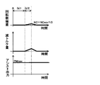
- FIG. 10 shows the construction machine when the engine speed and the assist output are maximum and the engine 1 is operating at the target rotational speed, and the load of the hydraulic pump 3 gradually becomes heavy and the rotational speed deviation ⁇ N increases.
- An example of control is shown.
- the assist output is the maximum PMmax
- the set value NC of the rotational speed deviation is held at NCmin (that is, a value close to zero).
- the engine and the assist output are maximum and the load of the hydraulic pump 3 is balanced.
- the set value NC of the rotational speed deviation is held at a value close to zero (NCmin), but since the rotational speed deviation ⁇ N does not occur, the pump absorption torque upper limit value is not limited.
- the period (b) 2 starts and the load of the hydraulic pump 3 starts to increase, the engine 1 and the motor / generator 2 have already reached the maximum output. ⁇ N begins to increase. As a result, the rotational speed deviation ⁇ N exceeds the set value NCmin, so that the pump absorption torque upper limit value is limited and a reduced torque amount is generated.
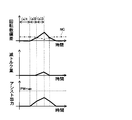
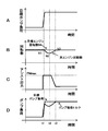
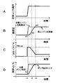
- FIG. 11 shows one example of control of the construction machine when the load of the hydraulic pump 3 increases rapidly in a situation where the actual rotational speed of the engine 1 is operating at a constant target rotational speed N *. .
- the assist output calculation unit 19 performs the motor torque command value from an operating point with a small rotation speed deviation ⁇ N according to the calculation of the power assist calculation unit 42 using the feedforward input in order to cope with a sudden increase in pump load.
- the maximum assist output PMmax is calculated, and the motor / generator 2 generates the maximum assist output PMmax as shown by a graph C in FIG.
- the maximum assist output is generated in this way, the set value of the rotational speed deviation is set to the minimum value NCmin, but the generated rotational speed deviation ⁇ N is small. Therefore, the pump absorption torque around time t1 when the load is applied to the hydraulic pump 3 is not so limited with respect to the target pump absorption torque (target pump load) as shown in the graph D in FIG. Absent.
- the engine 1 when the engine 1 operates at a constant target rotational speed N * and the motor / generator 2 generates a sufficient assist output, when the pump load increases and the rotational speed deviation ⁇ N occurs, By limiting the pump absorption torque upper limit value, the engine 1 can be returned to the target rotational speed N * without further increasing the assist output. This also reduces lag down. Furthermore, when the increase in the pump load can be covered by the assist output from the motor / generator 2, the engine speed does not drop, so the upper limit of the pump absorption torque is not limited, and the operability of the front work device is reduced. There is no loss.
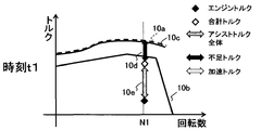
- FIG. 12 is a torque diagram corresponding to each time t1, t2, t3 in FIG. Next, the behavior of the torque of the engine 1, the motor / generator 2, and the hydraulic pump 3 at each time t1 to t3 will be described with reference to FIG.
- FIG. 12A is a torque diagram corresponding to time t1 in FIG.
- the line indicated by reference numeral 10a in FIG. 12A is the reference absorption torque upper limit value set using FIG. 2, and the line indicated by reference numeral 10b indicates the maximum torque characteristic of the engine 1 at each rotational speed.
- the actual engine speed N1 of the engine 1 matches the target engine speed N * and there is no engine speed deviation ⁇ N, but the power assist calculation unit 42 feeds forward output as the load of the hydraulic pump 3 increases.
- the maximum torque is calculated as follows, and the motor / generator 2 executes the engine assist 10e with the maximum torque. As a result, the assist output becomes the maximum value PMmax, and the set value of the rotational speed deviation is set to the minimum value NCmin.
- the limiting characteristic of the pump absorption torque upper limit value corresponds to 5B in FIG.
- the rotational speed deviation ⁇ N that occurs thereafter is small, the amount of torque reduction of the hydraulic pump 3 becomes small. Therefore, the absorption torque of the hydraulic pump 3 is controlled so as to have an upper limit 10c that is substantially equivalent to the specified maximum absorption torque line 10a. At this time, a slight lag-down occurs due to a shortage 10d of the torque sum (total torque) of the engine 1 and the motor / generator 2.
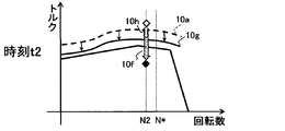
- FIG. 12B is a torque diagram corresponding to time t2 in FIG.
- the rotational speed deviation ⁇ N (deviation between the actual rotational speed N2 and the target rotational speed N *) is greater than immediately after the time t1.
- the assist torque 10f is the same as that in FIG. 12A.
- the pump absorption torque upper limit value is further limited by the increase in the rotational speed deviation ⁇ N.
- the absorption torque of the hydraulic pump 3 becomes an absorption torque line 10g that is limited with respect to the specified maximum absorption torque line 10a.
- the torque sum of the engine 1 and the motor / generator 2 is the same. Produces a surplus of 10 h for the pump load. Since the engine 1 can be accelerated to the target rotational speed N * by the surplus torque 10h, the actual rotational speed of the engine 1 can be increased without generating a transient large assist output.
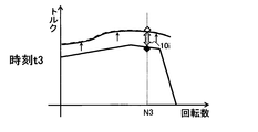
- FIG. 12C is a torque diagram corresponding to time t3 in FIG.
- the rotational speed deviation ⁇ N is eliminated by the surplus torque 10h, and the actual rotational speed N3 and the target rotational speed N * coincide.
- the upper limit of the absorption torque of the hydraulic pump 3 is not limited, and the maximum absorption torque line 10a of the hydraulic pump 3 is used as it is.
- the pump torque of 10a exceeds the maximum torque of the engine 1 from the viewpoint of improving fuel efficiency. Therefore, for the insufficient torque, the value calculated as the power assist amount 10 i by the assist output calculation unit 19 is output by the motor / generator 2. Since the torque of engine 1 is the maximum torque at time t3, power assist amount 10i is smaller than power assist amount 10e at time t1. At time t3, since the load limitation of the hydraulic pump 3 is not performed, sufficient operability can be secured in this region.
- the motor / generator 2 itself can be a small one with low output. Furthermore, the fact that the electric power consumption by the motor / generator 2 is small means that, when a capacitor is used as the power storage device 10, an improvement in efficiency is realized by reducing charge / discharge. In addition, even when a battery is used for the power storage device 10, the amount of discharge can be reduced, so that the power storage device 10 can be downsized.
- the rotational speed deviation ⁇ N increases, and normally in a situation where there is a possibility of lag down, the assist output is reduced.
- the upper limit of the pump absorption torque is limited.
- the engine speed can be quickly returned to the target speed, so that a state in which a high load is applied to the engine 1 can be reduced, and the occurrence of lag down can be suppressed.
- the pump absorption torque upper limit value is limited, and the situation where the engine 1 is overloaded can be prevented, so that the exhaust gas situation can be improved and the fuel consumption can be reduced.
- FIG. 13 shows one example of control of the construction machine when the target rotational speed of the engine 1 is suddenly increased to cope with the sudden increase in the load of the hydraulic pump 3.
- the target rotational speed setting unit 17 quickly raises the target rotational speed as shown by a graph C in FIG. 13 to increase the engine output in order to cope with a rapid increase in pump load. That is, the rotational speed deviation ⁇ N temporarily increases.
- the assist output calculation unit 19 calculates the maximum assist output PMmax as the motor torque command value in order to eliminate the generated rotation speed deviation ⁇ N, and the motor / generator 2 is as shown by a graph C in FIG. The maximum assist output PMmax is generated.
- the set value of the rotational speed deviation is set to the minimum value NCmin.
- the absorption torque upper limit calculation unit 23 takes a large amount of torque reduction.
- the pump absorption torque upper limit value is greatly reduced, and the pump load is greatly limited with respect to the target as shown by a graph D in FIG.
- the rotational speed deviation ⁇ N decreases as the actual rotational speed of the engine 1 approaches the target rotational speed
- the assist output by the motor / generator 2 gradually decreases.
- the characteristic diagram of the pump absorption torque gradually changes from the state of 5B in FIG. 7 to 5A and further to 5C, so that the limit of the pump absorption torque upper limit value is released as the rotational speed deviation ⁇ N decreases.
- the operability of the front working device can be maintained constantly.
- FIG. 14 is a torque diagram corresponding to each time t1, t2, t3 in FIG. Next, the behavior of the torque of the engine 1, the motor / generator 2, and the hydraulic pump 3 at each time t1 to t3 will be described with reference to FIG.
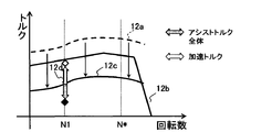
- FIG. 14A is a torque diagram corresponding to time t1 in FIG.
- the line indicated by the reference numeral 12a in FIG. 14A is the reference absorption torque upper limit value set using FIG. 2, and the line indicated by the reference numeral 12b indicates the characteristic of the maximum torque of the engine 1 at each rotational speed.
- the assist output becomes the maximum value PMmax, and the set value of the rotational speed deviation is set to the minimum value NCmin. Therefore, the limiting characteristic of the pump absorption torque upper limit value corresponds to 5B in FIG.
- the absorption torque of the hydraulic pump 3 is largely limited from the prescribed maximum absorption torque line 12a, and as a result, is controlled by the pump absorption torque upper limit value indicated by the line labeled 12c. For this reason, since the surplus 12d of the torque sum of the engine 1 and the motor / generator 2 is used as an acceleration for increasing the engine speed, the engine speed can be quickly raised. Moreover, since it can prevent that the excessive load is applied to the engine 1, it can avoid that a lag down generate
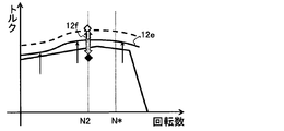
- FIG. 14B is a torque diagram corresponding to time t2 in FIG. Since the rotational speed deviation ⁇ N (deviation between the actual rotational speed N2 and the target rotational speed N *) is smaller than the time t1, the engine assist by the motor / generator 2 is smaller than that in FIG. 14A. Therefore, the limiting characteristic of the pump absorption torque upper limit value is from the state 5B in FIG. 7 to the state 5A, and the pump absorption torque is limited according to the rotational speed deviation ⁇ N at this time. Thereby, the absorption torque of the hydraulic pump 3 is controlled by the pump absorption torque upper limit value indicated by the line with the reference numeral 12e that is less restrictive than in FIG. 14A. Thereby, similarly to the time t1, the engine speed can be accelerated by the surplus portion 12f of the torque sum of the engine 1 and the motor / generator 2.
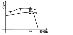
- FIG. 14C is a torque diagram corresponding to time t3 in FIG.
- the upper limit of the absorption torque of the hydraulic pump 3 is not limited, and the maximum absorption torque line 12a of the hydraulic pump 3 is used as it is.
- the pump torque of 12a exceeds the maximum torque of the engine 1 from the viewpoint of improving fuel efficiency. Therefore, for the insufficient torque, the value calculated as the power assist amount 12 g by the assist output calculation unit 19 is output by the motor / generator 2.
- the load limitation of the hydraulic pump 3 is not performed, sufficient operability can be secured in this region.
- the acceleration assist by the motor / generator 2 can be reduced by reducing the pump absorption torque upper limit value during acceleration.
- the enlargement of the machine 2 and the power storage device 10 can be suppressed.
- the actual engine speed of the engine 1 can be quickly increased to the target engine speed, the engine 1 can be avoided from being overloaded, and high-concentration combustion can be suppressed and exhaust gas can be improved. It is done.
- efficiency can be improved by reducing charge / discharge, so that power saving can be realized.
- the pump load is temporarily reduced temporarily when the load suddenly increases, there is a concern that the responsiveness to the operation of the front working device may be lost at that time.
- the load of a construction machine suddenly increases because the operation of the front work device does not move quickly, such as the start of excavation, so there are few actual situations where the operability deteriorates. Therefore, according to the present embodiment, the operability of the front working device can be ensured.
- the setting value NC of the rotational speed deviation is set in association with the magnitude of the assist output
- the setting value NC may be set in association with the magnitude of the power storage amount of the power storage device 10.
- both the amount of stored electricity and the assist output may be set in association with each other.
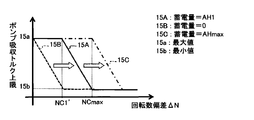
- FIG. 15 is a diagram showing the relationship between the rotational speed deviation setting value NC and the amount of power stored in the power storage device 10 in the present embodiment.
- the set value NC shown in this figure takes a minimum value of zero when the storage amount AH is zero, takes a maximum value NCmax when the storage amount AH is the maximum AMmax, and decreases as the storage amount of the storage device 10 decreases. It is set to be.
- FIG. 16 is a diagram illustrating an example of a change in the characteristic diagram of the pump absorption torque upper limit when the amount of power stored in the power storage device 10 changes (that is, when the set value NC changes).
- a reference characteristic diagram that is translated in the horizontal direction (horizontal axis direction) in accordance with the amount of storage will be described as a characteristic diagram for each amount of storage (in this case, the characteristics are matched to the increase in the amount of storage)
- the figure translates to the right as indicated by the arrows in the figure).
- the set value NC may be set to be smaller as the power generation amount is larger. That is, the larger the power generation amount, the closer to the characteristic diagram of 15B.
- a characteristic diagram of 15B is used when power generation is performed by the motor / generator 2, and the target rotational speed of the engine 1 at this time is a high-speed region in which high-efficiency power generation by the motor / generator 2 is possible.
- the rotational speed deviation ⁇ N temporarily occurs until the target rotational speed is reached.
- the output determination unit 43 of the assist output calculation unit 19 slightly accelerates the motor torque command without setting the motor torque command until the engine speed rises sufficiently. It is preferable to perform the assist or to set the motor / generator 2 so as not to be a load on the engine 1 so as to keep the torque at 0. With this setting, the extent to which the electric power generated by the motor / generator 2 becomes a load on the engine 3 is reduced, the time required to increase the actual rotational speed of the engine 1 to the target rotational speed can be shortened, and high efficiency is achieved. This is because power generation in the rotational speed region is possible, and fuel consumption can be improved.
Abstract
A device is provided with a target rotation speed setting unit (17) which sets a target rotation speed of an engine (1), a load detection means (21) for detecting a load of a hydraulic pump (3), an assist output calculation unit (19) which calculates an assist output generated by a motor/generator (2) on the basis of a rotation speed deviation ∆N, which is a difference between an actual rotation speed and the target rotation speed, or the load of the hydraulic pump, an absorption torque upper limit calculation unit (23) which calculates an absorption torque upper limit value of the hydraulic pump (3), and an operation signal generation unit (24) which generates an operation signal to be output to a pump content adjustment device (45). The absorption torque upper limit calculation unit reduces the absorption torque upper limit value of the hydraulic pump from the value calculated, when the rotation speed deviation ∆N is equal to or larger than a set value NC which is set in accordance with a degree of the assist output.
Description
本発明は、油圧ショベルやホイールローダ等の油圧アクチュエータを備えるハイブリッド式建設機械に係り、特にその制御装置に関する。
The present invention relates to a hybrid construction machine including a hydraulic actuator such as a hydraulic excavator or a wheel loader, and more particularly to a control device thereof.
油圧システムによって駆動される油圧ショベル等の建設機械では、軽負荷から重負荷までの全ての作業に対応できるように、最大負荷時の作業を見込んで選定した大型のエンジンを備えていることが多い。しかし、このように大型のエンジンを備えても、建設機械の作業全体において重負荷となる作業(例えば、油圧ショベルにおいて土砂の掘削・積み込みを頻繁に行う重掘削作業時)はあくまでも一部であり、軽負荷時や中負荷時(例えば、油圧ショベルにおいて地面を均すための水平引き作業を行う軽掘削作業時)にエンジンの能力が余ってしまうので、燃料消費量(以下、燃費と略すことがある)を低減する観点からは好ましくない傾向がある。この点を鑑みて、燃費低減のためにエンジンを小型化するとともに、エンジンの小型化に伴う出力不足を電動・発電機による出力で補助(アシスト)するハイブリッド式建設機械が知られている。
Construction machines such as hydraulic excavators driven by a hydraulic system often have a large engine that is selected for work at maximum load so that it can handle all work from light loads to heavy loads. . However, even with such a large engine, the work that causes heavy loads in the entire work of the construction machine (for example, during heavy excavation work in which excavation and loading of earth and sand is frequently performed in a hydraulic excavator) is only a part. Since the engine capacity is surplus at light load and medium load (for example, light excavation work that performs leveling work to level the ground in a hydraulic excavator), fuel consumption (hereinafter abbreviated as fuel consumption) There is a tendency that is not preferable from the viewpoint of reducing. In view of this point, a hybrid construction machine is known in which an engine is downsized to reduce fuel consumption, and an output shortage due to the downsizing of the engine is assisted by output from an electric motor / generator.
ハイブリッド式建設機械に関する技術としては、例えば、特開2007-218111号公報に記載されているものがある。この技術は、アイドル状態から即座に作業に復帰する場合等、低速回転中のエンジンを急加速する場合におけるオペレータの操作フィーリングの向上を図ったものである。この技術に係るハイブリッド式建設機械の制御装置は、エンジン(電動・発電機)の目標回転数、電動・発電機の実回転数及び蓄電器の残量に基づいて、電動・発電機によるアシスト出力の発生が必要か否かを判断する判定手段を備えており、当該判定手段においてアシスト出力の発生が不要であると判断された場合には、油圧ポンプが吸収可能な最大吸収トルクを示す最大トルク線として、エンジン目標回転数の上昇とともに最大吸収トルクを増加させる第1最大トルク線を選択し、一方、当該判定手段においてアシスト出力の発生が必要であると判断された場合には、最大トルク線として、第1最大トルク線と比較してエンジン低回転領域で最大吸収トルクが大きくなる第2最大トルク線を選択している。これにより、電動・発電機によるアシスト出力を発生する場合には、エンジン回転数の上昇時における油圧ポンプの吸収トルクがアシスト出力を発生しない場合と比較して大きくなるため、操作レバーの動きに対して建設機械の動き出しが早くなり、オペレータに与える操作フィーリングの違和感が軽減される。
As a technology related to a hybrid construction machine, for example, there is one described in Japanese Patent Application Laid-Open No. 2007-218111. This technique is intended to improve the operational feeling of the operator when the engine that is rotating at a low speed is suddenly accelerated, such as when returning to work immediately from the idle state. The control device for a hybrid construction machine according to this technology is based on the target rotational speed of the engine (electric motor / generator), the actual rotational speed of the electric motor / generator, and the remaining capacity of the battery. A determination unit that determines whether or not generation is necessary, and when the determination unit determines that generation of an assist output is unnecessary, a maximum torque line indicating a maximum absorption torque that can be absorbed by the hydraulic pump; If the first maximum torque line that increases the maximum absorption torque with the increase in the engine target speed is selected, and the determination means determines that the generation of the assist output is necessary, the maximum torque line is The second maximum torque line is selected in which the maximum absorption torque is larger in the engine low speed region than the first maximum torque line. As a result, when the assist output by the motor / generator is generated, the absorption torque of the hydraulic pump when the engine speed increases is larger than when the assist output is not generated. As a result, the construction machine starts moving quickly, and the uncomfortable feeling of operation given to the operator is reduced.
ところで、ハイブリッド式建設機械において燃費低減を図るためには、エンジンだけでなく、電動・発電機の消費電力低減と小型化を図ることが好ましい。
Incidentally, in order to reduce fuel consumption in a hybrid construction machine, it is preferable to reduce power consumption and size of not only the engine but also the motor / generator.
ここで、この観点から上記技術を検討する。上記技術では、エンジン回転数に応じて油圧ポンプの最大吸収トルクを一意に決定しており、さらに、電動・発電機でエンジンをアシストする場合には低回転数領域で最大吸収トルクを他の場合よりも大きな値としている。そのため、当該低回転数領域でエンジンを動作させている最中に作業装置に大きな負荷が加わった場合には、当然エンジンにも大きな負荷が加わることになる。したがって、電動・発電機によるエンジントルクアシストが不足したり遅れたりすると、エンジン回転数が落ち込むラグダウンが生じたり、場合によってはエンジンストールが生じる可能性がある。ラグダウンの発生は、エンジン回転数を目標回転数へ復帰させようとする急激な燃料噴射による黒煙の発生などの排ガス状況や燃費の悪化を招くことになる。また、エンジン回転数の減少に伴うエンジン音の変化がオペレータに不快感を与える。
Here, the above technology is examined from this viewpoint. In the above technology, the maximum absorption torque of the hydraulic pump is uniquely determined according to the engine speed, and when assisting the engine with an electric motor / generator, the maximum absorption torque is set in the low speed range in other cases. The value is larger than. For this reason, when a large load is applied to the work device while the engine is operating in the low rotation speed region, naturally, a large load is also applied to the engine. Therefore, if engine torque assist by the motor / generator is insufficient or delayed, there may be a lag down in which the engine speed drops, or an engine stall may occur. The occurrence of lag down leads to deterioration of exhaust gas conditions such as generation of black smoke due to rapid fuel injection to return the engine speed to the target speed and fuel consumption. In addition, the change in engine sound accompanying the decrease in engine speed makes the operator uncomfortable.
このような事態を回避するためには、電動・発電機によって過渡的に大きなアシスト出力を発生する必要がある。しかし、大きなアシスト出力を発生させると、電力消費量が大きくなり、小型化したエンジンを電動・発電機でアシストすることで燃費向上を図るという当初の設計趣旨に反して燃費が悪化する。また、大きなトルクアシストを行うためには、電動・発電機のサイズを大きくする必要があるが、これは電動・発電機に電力を供給するための蓄電装置の容量増加にもつながる。そのため、電動コンポーネントの小型化、ひいては建設機械そのものの小型化も困難になる。
In order to avoid such a situation, it is necessary to generate a large assist output transiently by the motor / generator. However, if a large assist output is generated, the power consumption increases, and the fuel efficiency deteriorates against the original design intent of improving the fuel efficiency by assisting a miniaturized engine with a motor / generator. In order to perform a large torque assist, it is necessary to increase the size of the electric motor / generator, which leads to an increase in the capacity of the power storage device for supplying electric power to the electric motor / generator. For this reason, it is difficult to reduce the size of the electric component, and thus the size of the construction machine itself.
本発明は、このような問題を解消するためになされたもので、エンジンを加速する際に、電動・発電機による過渡的なアシスト出力を抑える省電力で低燃費なハイブリッド式建設機械の制御装置を提供することを目的とする。
The present invention has been made to solve such problems, and is a power-saving and fuel-efficient control device for a hybrid construction machine that suppresses transient assist output by an electric motor / generator when the engine is accelerated. The purpose is to provide.
本発明は、上記目的を達成するために、エンジンと、このエンジンによって駆動される可変容量型の油圧ポンプと、この油圧ポンプから吐出される圧油によって駆動される油圧アクチュエータと、前記エンジンとの間でトルクの伝達を行う電動・発電機と、この電動・発電機に電力を供給する蓄電手段と、操作信号に基づいて前記油圧ポンプの容量を調節するポンプ容量調節手段とを備える建設機械の制御装置において、前記エンジンの実回転数を検出する実回転数検出手段と、前記エンジンの目標回転数を定める目標回転数設定手段と、前記油圧ポンプの負荷を検出する負荷検出手段と、前記実回転数検出手段から入力される実回転数と前記目標回転数設定手段から入力される前記目標回転数との差である回転数偏差、又は前記負荷検出手段から入力される前記油圧ポンプの負荷に基づいて、前記電動・発電機により発生させるアシスト出力を算出するアシスト出力演算手段と、前記油圧ポンプの吸収トルク上限値を算出する吸収トルク上限演算手段と、この吸収トルク上限演算手段で算出された値に基づいて前記油圧ポンプの容量を調節するために前記容量調節手段に出力する操作信号を生成する操作信号生成手段とを備え、前記吸収トルク上限演算手段は、前記回転数偏差が、前記アシスト出力演算手段で算出されるアシスト出力の大きさに応じて設定される設定値以上のとき、前記油圧ポンプの吸収トルク上限値を前記算出した値から低減するものとする。
In order to achieve the above object, the present invention includes an engine, a variable displacement hydraulic pump driven by the engine, a hydraulic actuator driven by pressure oil discharged from the hydraulic pump, and the engine. A construction machine comprising: an electric motor / generator for transmitting torque between the electric motor / electric generator; an electric storage means for supplying electric power to the electric motor / generator; and a pump capacity adjusting means for adjusting the capacity of the hydraulic pump based on an operation signal. In the control device, an actual rotational speed detecting means for detecting the actual rotational speed of the engine, a target rotational speed setting means for determining a target rotational speed of the engine, a load detecting means for detecting a load of the hydraulic pump, and the actual rotational speed Rotational speed deviation which is the difference between the actual rotational speed input from the rotational speed detection means and the target rotational speed input from the target rotational speed setting means, or the load detection An assist output calculating means for calculating an assist output generated by the motor / generator based on a load of the hydraulic pump input from a stage; an absorption torque upper limit calculating means for calculating an absorption torque upper limit value of the hydraulic pump; And an operation signal generating means for generating an operation signal to be output to the capacity adjusting means for adjusting the capacity of the hydraulic pump based on the value calculated by the absorption torque upper limit calculating means. The means reduces the absorption torque upper limit value of the hydraulic pump from the calculated value when the rotation speed deviation is equal to or larger than a set value set according to the magnitude of the assist output calculated by the assist output calculating means. It shall be.
本発明によれば、作業装置の負荷増加時におけるエンジン回転数の減少が防止できる
According to the present invention, it is possible to prevent the engine speed from decreasing when the load on the work device increases.
以下、本発明の実施の形態を図面を用いて説明する。図1は本発明の実施の形態である係るハイブリッド式油圧ショベルの油圧駆動制御装置の概略図である。この図に示す油圧駆動制御装置は、エンジン1と、エンジン1の燃料噴射量を調整するガバナ7と、エンジン1の実回転数を検出する回転数センサ(実回転数検出手段)16と、エンジン1のトルクを検出するエンジントルクセンサ(エンジントルク検出手段)31と、エンジン1により駆動される可変容量型油圧ポンプ3(以下、単に「油圧ポンプ3」と称することがある)と、油圧ポンプ3から吐出される圧油によって駆動される油圧アクチュエータ5と、エンジン1の駆動軸上に配置されエンジン1との間でトルクの伝達を行う電動・発電機2と、電動・発電機2に電力を供給する蓄電装置(蓄電手段)10と、油圧ポンプ3の容量を調節するポンプ容量調節装置(ポンプ容量調節手段)45と、電動・発電機2の回転数を制御して必要に応じて蓄電装置10と電力の授受を行うインバータ(電動・発電機制御手段)9と、ガバナ7を制御し燃料噴射量を調整してエンジン回転数を制御するとともに、インバータ9を制御し電動・発電機2のトルクを制御するコントローラ(制御装置)8を備えている。
Hereinafter, embodiments of the present invention will be described with reference to the drawings. FIG. 1 is a schematic diagram of a hydraulic drive control device for a hybrid hydraulic excavator according to an embodiment of the present invention. The hydraulic drive control device shown in this figure includes an engine 1, a governor 7 that adjusts the fuel injection amount of the engine 1, a rotation speed sensor (actual rotation speed detection means) 16 that detects the actual rotation speed of the engine 1, an engine 1, an engine torque sensor (engine torque detecting means) 31 for detecting the torque of 1, a variable displacement hydraulic pump 3 driven by the engine 1 (hereinafter simply referred to as “hydraulic pump 3”), and a hydraulic pump 3 A hydraulic actuator 5 driven by pressure oil discharged from the motor, a motor / generator 2 that is arranged on the drive shaft of the engine 1 and transmits torque to / from the engine 1, and power to the motor / generator 2 It is necessary to control the number of revolutions of the power storage device (power storage means) 10 to be supplied, the pump capacity adjustment device (pump capacity adjustment means) 45 for adjusting the capacity of the hydraulic pump 3, and the motor / generator 2. In response to this, the inverter (electric motor / generator control means) 9 for transferring power to and from the power storage device 10 and the governor 7 to adjust the fuel injection amount to control the engine speed and to control the inverter 9 for electric A controller (control device) 8 that controls the torque of the generator 2 is provided.
図1に示す油圧駆動制御装置は、油圧ポンプ3で吐出した圧油をまず複数のコントロールバルブを備えるバルブ装置4に供給し、当該バルブ装置4で圧油の流量・方向・圧力を適宜変更した後に各油圧アクチュエータ5に供給することで各油圧アクチュエータ5の駆動を制御している。本実施の形態に係る油圧ショベルに設置される油圧アクチュエータ5としては、上部旋回体の前方に取り付けられた多関節型のフロント作業装置を駆動するための油圧シリンダ(ブームシリンダ、アームシリンダ及びバケットシリンダ等)や、上部旋回体を旋回させるための油圧モータ(旋回モータ)や、上部旋回体の下部に取り付けられた下部走行体を走行させるための油圧モータ(走行モータ)等があるが、図1ではこれらをまとめて油圧アクチュエータ5と表記している。
The hydraulic drive control device shown in FIG. 1 first supplies the pressure oil discharged by the hydraulic pump 3 to a valve device 4 having a plurality of control valves, and the flow rate, direction, and pressure of the pressure oil are appropriately changed by the valve device 4. The drive of each hydraulic actuator 5 is controlled by supplying each hydraulic actuator 5 later. The hydraulic actuator 5 installed in the hydraulic excavator according to the present embodiment includes a hydraulic cylinder (boom cylinder, arm cylinder, and bucket cylinder) for driving an articulated front working device attached in front of the upper swing body. Etc.), a hydraulic motor (swing motor) for turning the upper turning body, a hydraulic motor (traveling motor) for running the lower traveling body attached to the lower part of the upper turning body, etc. These are collectively referred to as a hydraulic actuator 5.
エンジン1は、ガバナ7によって燃料噴射量を制御することで調速される。油圧ポンプ3には、油圧ポンプ3の負荷を演算するために必要な情報を検出する手段(ポンプ情報検出手段21)として、油圧ポンプ3から吐出される圧油の圧力を計測する吐出圧センサと、当該圧油の流量を計測する流量計と、油圧ポンプ3の傾転角を計測する傾転角センサとが設置されており、これら吐出圧センサ、流量計及び傾転角センサはコントローラ8に検出したセンサ値を出力している。コントローラ8におけるポンプ負荷演算部26(後述)は、このポンプ情報検出手段21から入力される各センサ値に基づいて油圧ポンプ3の負荷を演算する。
The engine 1 is regulated by controlling the fuel injection amount by the governor 7. The hydraulic pump 3 includes a discharge pressure sensor that measures the pressure of the pressure oil discharged from the hydraulic pump 3 as means (pump information detection means 21) for detecting information necessary for calculating the load of the hydraulic pump 3. A flow meter for measuring the flow rate of the pressure oil and a tilt angle sensor for measuring the tilt angle of the hydraulic pump 3 are installed. The discharge pressure sensor, the flow meter, and the tilt angle sensor are provided in the controller 8. The detected sensor value is output. A pump load calculation unit 26 (described later) in the controller 8 calculates the load of the hydraulic pump 3 based on each sensor value input from the pump information detection means 21.
ポンプ容量調節装置45は、コントローラ8から出力される操作信号に基づいて油圧ポンプ3の容量を調節するもので、レギュレータ14と電磁比例弁15を有している。レギュレータ14は油圧ポンプ3に備えられており、レギュレータ14によって油圧ポンプ3の斜板もしくは斜軸の傾転角を操作すると、油圧ポンプ3の容量(押しのけ容積)が変更されて油圧ポンプ3の吸収トルク(入力トルク)を制御することができる(ポンプ吸収トルク制御)。本実施の形態におけるレギュレータ14は、電磁比例弁15が発生する制御圧によって制御されている。電磁比例弁15は、コントローラ8における操作信号生成部24(後述)から出力される指令値に基づいて作動する。
The pump capacity adjusting device 45 adjusts the capacity of the hydraulic pump 3 based on an operation signal output from the controller 8 and includes a regulator 14 and an electromagnetic proportional valve 15. The regulator 14 is provided in the hydraulic pump 3, and when the tilt angle of the swash plate or the oblique shaft of the hydraulic pump 3 is operated by the regulator 14, the capacity (displacement volume) of the hydraulic pump 3 is changed and absorption of the hydraulic pump 3 is performed. Torque (input torque) can be controlled (pump absorption torque control). The regulator 14 in this embodiment is controlled by the control pressure generated by the electromagnetic proportional valve 15. The electromagnetic proportional valve 15 operates based on a command value output from an operation signal generation unit 24 (described later) in the controller 8.
本実施の形態に係るレギュレータ14は、例えば、図2に示した制御特性図に従って油圧ポンプ3の容量を制御している。図2は本発明の実施の形態に係るレギュレータ14によるポンプ吸収トルクの制御特性図である。この図に示す折れ線2Aは、油圧ポンプ3の吐出圧に対して設定される油圧ポンプ3の容量の特性を示しており、エンジン1と電動・発電機2の合計出力の最大値(図2中の破線で示した双曲線(一定トルク線図))を超えない範囲で油圧ポンプ3のトルク(ポンプ容量とポンプ吐出圧力の積)がほぼ一定になるように設定されている。すなわち、その時々のポンプ吐出圧力に応じて折れ線2Aを利用して油圧ポンプ3の容量を設定すれば、エンジン1と電動・発電機2による最大出力を超えないように油圧ポンプ3のトルクを制御できる。ポンプ吐出圧力がP1以下である時にはポンプ吸収トルク制御は実施されず、ポンプ容量はバルブ装置4の各コントロールバルブを操作するための操作レバーの操作量によって決定される(例えば、いずれかの操作レバーの操作量が最大の時にq1になる)。一方、ポンプ吐出圧力がP1~P2になると、レギュレータ14によるポンプ吸収トルク制御が実施され、ポンプ吐出圧の増加に伴って折れ線2Aに沿ってポンプ容量が減少するようにレギュレータ14によってポンプ傾転角が操作される。これにより、ポンプ吸収トルクは、折れ線2Aで規定したトルク以下になるように制御される。なお、P2はポンプ吐出圧力の最大値であり、バルブ装置2において油圧ポンプ3側の回路に接続されるリリーフ弁の設定圧力に等しく、ポンプ吐出圧力はこの値以上に上昇しない。なお、ここでは、油圧ポンプの吸収トルクの制御特性図として、2つの直線を組み合わせた折れ線2Aを使用したが、図2中の一定トルク線図(双曲線)を超えない範囲で設定すれば他の制御特性図を利用しても良い。 コントローラ8は、油圧ポンプ3の吸収トルクに基づいて生成した操作信号(電気信号)を電磁比例弁15に出力し、電磁比例弁15は当該操作信号に応じた制御圧力を生成することでレギュレータ14を駆動する。これによりレギュレータ14によって油圧ポンプ3の容量が変更され、油圧ポンプ3の吸収トルクはエンジンストールが発生しない範囲に調整される。
For example, the regulator 14 according to the present embodiment controls the capacity of the hydraulic pump 3 according to the control characteristic diagram shown in FIG. FIG. 2 is a control characteristic diagram of pump absorption torque by the regulator 14 according to the embodiment of the present invention. A broken line 2A shown in this figure indicates the characteristic of the capacity of the hydraulic pump 3 set with respect to the discharge pressure of the hydraulic pump 3, and the maximum value of the total output of the engine 1 and the motor / generator 2 (in FIG. 2). The torque (product of pump capacity and pump discharge pressure) of the hydraulic pump 3 is set to be substantially constant within a range not exceeding the hyperbola (constant torque diagram) indicated by the broken line. That is, if the capacity of the hydraulic pump 3 is set using the broken line 2A according to the pump discharge pressure at that time, the torque of the hydraulic pump 3 is controlled so as not to exceed the maximum output by the engine 1 and the motor / generator 2. it can. When the pump discharge pressure is P1 or less, the pump absorption torque control is not performed, and the pump capacity is determined by the operation amount of the operation lever for operating each control valve of the valve device 4 (for example, any one of the operation levers) Q1 when the operation amount is maximum). On the other hand, when the pump discharge pressure becomes P1 to P2, pump absorption torque control is performed by the regulator 14, and the pump tilt angle is adjusted by the regulator 14 so that the pump capacity decreases along the broken line 2A as the pump discharge pressure increases. Is operated. Thereby, the pump absorption torque is controlled to be equal to or less than the torque defined by the broken line 2A. Note that P2 is the maximum value of the pump discharge pressure, which is equal to the set pressure of the relief valve connected to the circuit on the hydraulic pump 3 side in the valve device 2, and the pump discharge pressure does not increase above this value. Here, a polygonal line 2A that combines two straight lines is used as a control characteristic diagram of the absorption torque of the hydraulic pump, but other values can be set as long as they do not exceed the constant torque diagram (hyperbola) in FIG. A control characteristic diagram may be used. The controller 8 outputs an operation signal (electrical signal) generated based on the absorption torque of the hydraulic pump 3 to the electromagnetic proportional valve 15, and the electromagnetic proportional valve 15 generates a control pressure corresponding to the operation signal to thereby generate a regulator 14. Drive. As a result, the capacity of the hydraulic pump 3 is changed by the regulator 14, and the absorption torque of the hydraulic pump 3 is adjusted to a range in which engine stall does not occur.
バッテリ又はキャパシタ等で構成される蓄電装置10には、蓄電装置10の蓄電量を演算するために必要な情報を検出する手段(蓄電情報検出手段22)として、電流センサ11、電圧センサ12及び温度センサ13が取り付けられている。コントローラ8は、これらセンサ11,12,13によって検出された電流、電圧及び温度等の情報に基づいて蓄電量演算部25(後述)において蓄電装置10の蓄電量を演算し、蓄電装置10の蓄電量を管理している。
The power storage device 10 constituted by a battery, a capacitor, or the like includes a current sensor 11, a voltage sensor 12, and a temperature as means (power storage information detection means 22) for detecting information necessary for calculating the amount of power stored in the power storage device 10. A sensor 13 is attached. Based on information such as current, voltage, and temperature detected by these sensors 11, 12, and 13, the controller 8 calculates the amount of power stored in the power storage device 10 in a power storage amount calculation unit 25 (described later). Manage the amount.
図3は本発明の実施の形態におけるコントローラ8の概略構成図である。この図に示すコントローラ8は、エンジン1、電動・発電機2及び油圧ポンプ3に対するそれぞれの指令値の演算を行うもので、目標回転数設定部(目標回転数設定手段)17と、エンジン最大出力演算部(エンジン最大出力演算手段)18と、アシスト出力演算部(アシスト出力演算手段)19と、吸収トルク上限演算部(吸収トルク上限演算手段)23と、操作信号生成部(操作信号生成手段)24と、蓄電量演算部25と、ポンプ負荷演算部26と、エンジン出力演算部32を備えている。
FIG. 3 is a schematic configuration diagram of the controller 8 according to the embodiment of the present invention. The controller 8 shown in this figure calculates the command values for the engine 1, the motor / generator 2 and the hydraulic pump 3, and includes a target rotational speed setting unit (target rotational speed setting means) 17 and an engine maximum output. Calculation unit (engine maximum output calculation unit) 18, assist output calculation unit (assist output calculation unit) 19, absorption torque upper limit calculation unit (absorption torque upper limit calculation unit) 23, operation signal generation unit (operation signal generation unit) 24, a power storage amount calculation unit 25, a pump load calculation unit 26, and an engine output calculation unit 32.
コントローラ8には、回転数センサ(実回転数検出手段)16によって検出されるエンジン実回転数と、エンジントルクセンサ(エンジントルク検出手段)31によって検出されるエンジントルクと、蓄電情報検出手段22によって検出された蓄電情報(蓄電装置10の電流、電圧及び温度)と、ポンプ情報検出手段21によって検出されたポンプ情報(圧油の圧力及び流量並びに油圧ポンプ3の傾転角)と、油圧ショベルの運転室(キャブ)内に設置されオペレータによって所望の目標エンジン回転数が入力される目標回転数入力装置29(例えば、エンジンコントロールダイヤル)から入力される目標エンジン回転数が入力されている。
The controller 8 includes an engine actual speed detected by a speed sensor (actual speed detecting means) 16, an engine torque detected by an engine torque sensor (engine torque detecting means) 31, and a storage information detecting means 22. The detected power storage information (current, voltage and temperature of the power storage device 10), the pump information detected by the pump information detection means 21 (pressure and pressure of hydraulic oil and the tilt angle of the hydraulic pump 3), and the hydraulic excavator A target engine speed input from a target speed input device 29 (for example, an engine control dial) installed in the cab (cab) and to which a desired target engine speed is input by an operator is input.
蓄電量演算部25は、電流センサ11、電圧センサ12及び温度センサ13(蓄電情報検出手段22)から入力される蓄電情報に基づいて蓄電装置10の蓄電量を演算する部分であり、蓄電情報検出手段22とともに蓄電量検出部27を構成している。蓄電量演算部25で演算された蓄電量は、アシスト出力演算部19及び吸収トルク上限演算部22に出力されている。
The power storage amount calculation unit 25 is a portion that calculates the power storage amount of the power storage device 10 based on the power storage information input from the current sensor 11, the voltage sensor 12, and the temperature sensor 13 (power storage information detection means 22). A storage amount detection unit 27 is configured together with the means 22. The storage amount calculated by the storage amount calculation unit 25 is output to the assist output calculation unit 19 and the absorption torque upper limit calculation unit 22.
ポンプ負荷演算部26は、吐出圧センサ、流量計及び傾転角センサ(ポンプ情報検出手段21)から入力されるポンプ情報に基づいて油圧ポンプ3の負荷を演算する部分であり、ポンプ情報検出手段21とともにポンプ負荷検出部28を構成している。ポンプ負荷演算部26で演算されたポンプ負荷は、アシスト出力演算部19に出力されている。
The pump load calculation unit 26 is a part that calculates the load of the hydraulic pump 3 based on the pump information input from the discharge pressure sensor, the flow meter, and the tilt angle sensor (pump information detection means 21). 21 constitutes a pump load detection unit 28. The pump load calculated by the pump load calculation unit 26 is output to the assist output calculation unit 19.
エンジン出力演算部32は、エンジントルクセンサ31から入力されるエンジントルクに基づいてエンジン1の実際の出力を演算する部分であり、エンジントルクセンサ31とともにエンジン出力検出部(エンジン出力検出手段)20を構成している。エンジン出力演算部32で演算された出力はアシスト出力演算部19に出力されている。
The engine output calculation unit 32 is a part that calculates the actual output of the engine 1 based on the engine torque input from the engine torque sensor 31. The engine output detection unit (engine output detection means) 20 is operated together with the engine torque sensor 31. It is composed. The output calculated by the engine output calculation unit 32 is output to the assist output calculation unit 19.
目標回転数設定部17は、ポンプ負荷演算部26で算出される油圧ポンプ3の負荷(油圧アクチュエータ5の負荷状態)に応じたエンジン出力が確保されるようにエンジン1の目標回転数を定める部分であり、当該目標回転数は目標回転数入力装置29から入力されるものよりも優先して決定される。なお、その際、エンジン1における燃料消費量を低減する観点から、エンジン1の必要出力に対する燃料消費量が最小となる動作点をエンジン1の目標回転数指令値として設定することが好ましい。目標回転数設定部17で定められた目標回転数は、吸収トルク上限演算部23と操作信号生成部24に出力されている。さらに、目標回転数は、回転数センサ16によって検出される実回転数との偏差としてアシスト出力演算部19に出力されている。なお、ここで定められる目標回転数は、発電・電動機2の制御にも利用されるが、エンジン1と電動・発電機2が減速機などを介して接続されている場合には、一旦定めた目標回転数に当該減速機の減速比を乗じた値を別途目標回転数として定義して利用すれば良い。
The target rotational speed setting unit 17 is a part that determines the target rotational speed of the engine 1 so that an engine output corresponding to the load of the hydraulic pump 3 (the load state of the hydraulic actuator 5) calculated by the pump load calculating unit 26 is secured. The target rotational speed is determined in preference to the target rotational speed input from the target rotational speed input device 29. At this time, from the viewpoint of reducing the fuel consumption in the engine 1, it is preferable to set the operating point at which the fuel consumption relative to the required output of the engine 1 is the minimum as the target rotational speed command value of the engine 1. The target rotational speed determined by the target rotational speed setting unit 17 is output to the absorption torque upper limit calculation unit 23 and the operation signal generation unit 24. Further, the target rotational speed is output to the assist output calculation unit 19 as a deviation from the actual rotational speed detected by the rotational speed sensor 16. The target rotational speed determined here is also used for control of the generator / motor 2, but once the engine 1 and the motor / generator 2 are connected via a speed reducer, etc. A value obtained by multiplying the target rotational speed by the reduction ratio of the reduction gear may be separately defined and used as the target rotational speed.
エンジン最大出力演算部18は、回転数センサ16から入力されるエンジン1の実回転数と、エンジン特性に応じて設定されたテーブルであって記憶装置(ROM等)に記憶されたものとに基づいて、エンジン1が出力可能な最大出力を演算する部分である。エンジン最大出力演算部18で演算された最大出力はアシスト出力演算部19に出力されている。
The engine maximum output calculation unit 18 is based on the actual engine speed input from the engine speed sensor 16 and a table set in accordance with engine characteristics and stored in a storage device (ROM or the like). Thus, the maximum output that the engine 1 can output is calculated. The maximum output calculated by the engine maximum output calculation unit 18 is output to the assist output calculation unit 19.
アシスト出力演算部19は、目標回転数設定部17で定められた目標回転数へとエンジン1を素早く加速するための加速アシストと、エンジン単体での出力の不足分を補うためのパワーアシストの両方を実現するために電動・発電機2が出力するべきモータトルク指令値(アシスト出力指令値)を演算する部分である。アシスト出力演算部19は、具体的には、回転数センサ16から入力される実回転数と目標回転数設定部17から入力される目標回転数との差である回転数偏差ΔN、又は、ポンプ負荷検出部28から入力される油圧ポンプ3の負荷に基づいて、電動・発電機2により発生させるアシスト出力(エンジンアシスト出力)を算出している。ここで図を用いてアシスト出力演算部19の詳細を説明する。
The assist output calculation unit 19 performs both acceleration assist for quickly accelerating the engine 1 to the target rotational speed determined by the target rotational speed setting unit 17 and power assist for compensating for an insufficient output of the engine alone. This is a part for calculating a motor torque command value (assist output command value) to be output by the motor / generator 2 in order to realize the above. Specifically, the assist output calculation unit 19 is a rotation speed deviation ΔN that is a difference between the actual rotation speed input from the rotation speed sensor 16 and the target rotation speed input from the target rotation speed setting section 17, or a pump Based on the load of the hydraulic pump 3 input from the load detector 28, the assist output (engine assist output) generated by the motor / generator 2 is calculated. Here, details of the assist output calculation unit 19 will be described with reference to the drawings.
図4は本発明の実施の形態におけるアシスト出力演算部19の概略構成図である。この図に示すアシスト出力演算部19は、加速アシスト演算部41と、パワーアシスト演算部42と、出力決定部43を備えている。
FIG. 4 is a schematic configuration diagram of the assist output calculation unit 19 in the embodiment of the present invention. The assist output calculation unit 19 shown in this figure includes an acceleration assist calculation unit 41, a power assist calculation unit 42, and an output determination unit 43.
加速アシスト演算部41は、エンジン1の実回転数を目標回転数まで速やかに加速するためにエンジン1の出力をアシストする場合(加速アシスト時)における電動・発電機2のアシスト出力(加速アシスト出力)を演算する部分であり、加速アシスト演算部41には、エンジン1の目標回転数と実回転数の差である回転数偏差ΔNが入力されている。加速アシスト演算部41では、アシスト出力は、エンジン1の目標回転数と実回転数の差である回転数偏差ΔNに基づいて演算され、回転数偏差ΔNがゼロに近づくほど小さくなる。加速アシスト演算部41では、回転数偏差ΔNが比較的大きいときにエンジン1の加速を素早く行う観点からは、主に微分制御と比例制御を利用してアシスト出力を演算することが好ましい。
The acceleration assist calculation unit 41 assists the output of the motor / generator 2 (acceleration assist output) when assisting the output of the engine 1 in order to quickly accelerate the actual rotational speed of the engine 1 to the target rotational speed (during acceleration assist). ), And the acceleration assist calculation unit 41 is input with a rotation speed deviation ΔN that is the difference between the target rotation speed of the engine 1 and the actual rotation speed. In the acceleration assist calculation unit 41, the assist output is calculated based on the rotational speed deviation ΔN that is the difference between the target rotational speed of the engine 1 and the actual rotational speed, and becomes smaller as the rotational speed deviation ΔN approaches zero. In the acceleration assist calculation unit 41, it is preferable to calculate the assist output mainly using differential control and proportional control from the viewpoint of quickly accelerating the engine 1 when the rotational speed deviation ΔN is relatively large.
パワーアシスト演算部42は、エンジン1の出力のみでは出力不足となるために電動・発電機2によるアシストが必要となる場合(パワーアシスト時)における電動・発電機2のアシスト出力(パワーアシスト出力)を演算する部分であり、パワーアシスト演算部42には、回転数偏差ΔNと、最大エンジン出力と、エンジン出力と、ポンプ負荷が入力されている。パワーアシスト演算部42では、アシスト出力は、ポンプ負荷演算部26から入力される油圧ポンプ3の負荷と、エンジン出力演算部32(エンジン出力検出部20)から入力されるエンジン出力との差に基づいて演算される。なお、この演算において、エンジン最大出力演算部18から入力されるエンジン最大出力を参照すると、その時におけるエンジン1の実回転数において必要となり得るパワーアシスト出力の最小値を算出することができる。エンジン1のみでは出力不足となる場合には定常的なアシスト出力が必要となることが多いので、パワーアシスト演算部42では、フィードフォワード入力や積分制御を利用してアシスト出力を演算することが好ましい。本実施の形態では、さらに、過負荷によるエンジンストールの発生を回避する観点から、フィードフォワード入力の演算において、ポンプ負荷検出部28によって検出されるポンプ負荷とエンジン出力検出部20で検出されたエンジン出力の差を電動・発電機2で発生すべきアシスト出力として算出している。
The power assist calculation unit 42 assists the motor / generator 2 when the assist by the motor / generator 2 is necessary because the output is insufficient only by the output of the engine 1 (during power assist) (power assist output). In the power assist calculation unit 42, the rotational speed deviation ΔN, the maximum engine output, the engine output, and the pump load are input. In the power assist calculation unit 42, the assist output is based on the difference between the load of the hydraulic pump 3 input from the pump load calculation unit 26 and the engine output input from the engine output calculation unit 32 (engine output detection unit 20). Is calculated. In this calculation, referring to the engine maximum output input from the engine maximum output calculation unit 18, the minimum value of the power assist output that can be required at the actual rotational speed of the engine 1 at that time can be calculated. When the engine 1 alone is insufficient in output, a steady assist output is often required. Therefore, the power assist calculation unit 42 preferably calculates an assist output using feedforward input or integral control. . In the present embodiment, from the viewpoint of avoiding the occurrence of engine stall due to overload, the pump load detected by the pump load detection unit 28 and the engine detected by the engine output detection unit 20 in the calculation of feedforward input. The difference in output is calculated as an assist output to be generated by the motor / generator 2.
出力決定部43は、加速アシスト演算部41とパワーアシスト演算部42で算出されたアシスト出力を加算し、当該加算後のアシスト出力に相当するモータトルク指令値を生成する部分であり、出力決定部43には、加速アシスト演算部41及びパワーアシスト演算部42で演算されたアシスト出力の和と、蓄電装置10の蓄電量が入力されている。また、出力決定部43は、蓄電量演算部25から入力される蓄電装置10の蓄電量が少ないためにアシスト演算部41,42で演算されたアシスト出力を発生できない場合に、電動・発電機2によるアシスト出力量を制限し、当該制限後のアシスト出力に対応するモータトルク指令値を算出する機能を有する。さらに、蓄電装置10の蓄電量が少なく(例えば、設定値未満の場合)かつエンジンアシストが不要な場合には、電動・発電機2に発電を実行させるモータトルク指令値を算出する機能を有する。
The output determination unit 43 is a part that adds the assist outputs calculated by the acceleration assist calculation unit 41 and the power assist calculation unit 42 and generates a motor torque command value corresponding to the assist output after the addition. 43, the sum of the assist outputs calculated by the acceleration assist calculation unit 41 and the power assist calculation unit 42 and the storage amount of the power storage device 10 are input. In addition, the output determination unit 43, when the storage amount of the power storage device 10 input from the storage amount calculation unit 25 is small and cannot generate the assist output calculated by the assist calculation units 41 and 42, the motor / generator 2 The assist output amount is limited, and the motor torque command value corresponding to the limited assist output is calculated. Furthermore, when the power storage amount of the power storage device 10 is small (for example, less than a set value) and engine assist is unnecessary, the motor / generator 2 has a function of calculating a motor torque command value for generating power.
なお、アシスト出力演算部19では、エンジン最大出力演算部18から入力されるエンジン最大出力と、エンジン出力検出部20から入力されるエンジン出力とに基づいて、電動・発電機2によるアシスト出力を演算しても良い。このようにすれば、電動・発電機によるアシスト出力は、エンジン1の現在の出力とその回転数におけるエンジン1の最大出力を判断材料に定められるので、エンジン1の出力に余裕があるうちには電動・発電機2によるアシストを実施せずに蓄電装置10の蓄電量を無駄に消費すること避けることができる。また、エンジン出力が最大値に達している場合には、すぐにアシストが実施されるため、エンストの回避が実現できるのはもちろんのこと、エンジン回転数を目標回転数へ応答良く追従することもできる。
The assist output calculation unit 19 calculates the assist output from the motor / generator 2 based on the engine maximum output input from the engine maximum output calculation unit 18 and the engine output input from the engine output detection unit 20. You may do it. In this way, the assist output by the motor / generator can be determined based on the current output of the engine 1 and the maximum output of the engine 1 at the number of rotations thereof. It is possible to avoid wasteful consumption of the power storage amount of the power storage device 10 without performing the assist by the motor / generator 2. In addition, when the engine output reaches the maximum value, the assist is performed immediately, so that the engine stall can be avoided as well as following the engine speed to the target speed with good response. it can.
図3に戻り、吸収トルク上限演算部23は、油圧ポンプ3の吸収トルク(入力トルク)の上限値(最大値)を演算する部分であり、ここで算出した吸収トルク上限値を操作信号生成部24に出力している。
Returning to FIG. 3, the absorption torque upper limit calculation unit 23 is a part that calculates the upper limit value (maximum value) of the absorption torque (input torque) of the hydraulic pump 3, and the absorption torque upper limit value calculated here is used as the operation signal generation unit. 24 is output.
本実施の形態における吸収トルク上限演算部33は、通常、図2に示した制御特性図に従ってポンプ吸収トルク上限値を算出する。しかし、回転数偏差ΔNが、設定値(以下、「設定値NC」と称することがある)以上のときには、図2の制御特性図に基づいて算出した値から更に所定の吸収トルクを低減した値をポンプ吸収トルク上限値として算出する。
The absorption torque upper limit calculation unit 33 in the present embodiment normally calculates the pump absorption torque upper limit value according to the control characteristic diagram shown in FIG. However, when the rotational speed deviation ΔN is equal to or greater than a set value (hereinafter sometimes referred to as “set value NC”), a value obtained by further reducing the predetermined absorption torque from the value calculated based on the control characteristic diagram of FIG. Is calculated as the pump absorption torque upper limit value.
図5は本実施の形態における回転数偏差の設定値NCとアシスト出力の関係を示す図である。この図に示すように、設定値NCは、アシスト出力演算部19で算出されるアシスト出力の大きさに応じて設定されている。さらに具体的には、この図に示す設定値NCは、アシスト出力PMがゼロのときに最大値NCmaxをとり、アシスト出力PMが最大のときに最小値NCminをとっており、電動・発電機2のアシスト出力が大きくなるほど小さくなるように設定されている。次に、回転数偏差ΔNが設定値NC以上の場合において吸収トルク上限演算部23で行われるポンプ吸収トルク制御ついて図を用いて説明する。
FIG. 5 is a diagram showing a relationship between the set value NC of the rotational speed deviation and the assist output in the present embodiment. As shown in this figure, the set value NC is set according to the magnitude of the assist output calculated by the assist output calculation unit 19. More specifically, the set value NC shown in this figure takes the maximum value NCmax when the assist output PM is zero, and takes the minimum value NCmin when the assist output PM is maximum. The assist output is set so as to decrease as the assist output increases. Next, pump absorption torque control performed by the absorption torque upper limit calculation unit 23 when the rotation speed deviation ΔN is equal to or larger than the set value NC will be described with reference to the drawings.
図6は回転偏差ΔNが設定値NC以上のときにおけるレギュレータ14によるポンプ吸収トルクの制御特性図の変化の一例である。例えば、説明を簡単にするために、アシスト出力が一定で設定値NCが一定値である場合において、回転数偏差ΔNが設定値NC未満の値から設定値NCより大きい値まで変化したとし、この図における折れ線7Aが図2における折れ線2Aに相当したとする。この場合には、本実施の形態における吸収トルク上限演算部23は、回転数偏差ΔNが設定値NC以上に達すると、回転数偏差ΔNと設定値NCの偏差の大きさに応じて、折れ線が7Aから7Bへ、さらには7Bから7Cへと遷移するようにポンプ吸収トルク上限値を低減する。このようにポンプ吸収トルク上限値を低減すると、回転数偏差ΔNの大きさに合わせてポンプ吸収トルクを低減することができるので、回転数偏差ΔNの大きさに合わせてエンジン1又は電動・発電機2の負荷を小さくすることができる。
FIG. 6 is an example of a change in the control characteristic diagram of the pump absorption torque by the regulator 14 when the rotation deviation ΔN is equal to or larger than the set value NC. For example, to simplify the explanation, when the assist output is constant and the set value NC is a constant value, it is assumed that the rotational speed deviation ΔN changes from a value less than the set value NC to a value greater than the set value NC. Assume that the polygonal line 7A in the figure corresponds to the polygonal line 2A in FIG. In this case, when the rotational speed deviation ΔN reaches or exceeds the set value NC, the absorption torque upper limit calculation unit 23 according to the present embodiment forms a broken line according to the magnitude of the deviation between the rotational speed deviation ΔN and the set value NC. The pump absorption torque upper limit value is reduced so as to transition from 7A to 7B and further from 7B to 7C. If the pump absorption torque upper limit value is reduced in this way, the pump absorption torque can be reduced in accordance with the magnitude of the rotational speed deviation ΔN, so that the engine 1 or the motor / generator is adapted to the magnitude of the rotational speed deviation ΔN. 2 can be reduced.
なお、制御特性(折れ線)は、回転数偏差ΔNと設定値NCの偏差の大きさに応じて段階的(例えば、図7に示した7A,7B,7Cの3段階)に遷移させても良いし、回転数偏差ΔNと設定値NCの偏差の大きさに応じて折れ線7Aから折れ線7Cまで徐々に遷移させても良い。後者の制御特性を利用すると、ポンプ吸収トルク上限値が急激に変化することが抑制できるので、前者の場合よりもフロント作業装置の操作性の悪化を抑制できる。また、制御特性の折れ線を遷移させるパラメータを関数で定義できるので、前者のように事前に多くのデータテーブルを用意せずに済む。次に、回転数偏差ΔNと設定値NCの偏差の大きさに応じて折れ線7Aから折れ線7Cまで徐々に遷移させた場合について、図を用いて説明する。
The control characteristic (broken line) may be changed stepwise (for example, three steps 7A, 7B, and 7C shown in FIG. 7) according to the magnitude of the deviation between the rotational speed deviation ΔN and the set value NC. Then, the transition may be made gradually from the broken line 7A to the broken line 7C according to the magnitude of the deviation between the rotational speed deviation ΔN and the set value NC. If the latter control characteristic is used, since it is possible to suppress the pump absorption torque upper limit from changing suddenly, it is possible to suppress the deterioration of the operability of the front work device compared to the former case. In addition, since the parameter for changing the line of control characteristics can be defined by a function, it is not necessary to prepare many data tables in advance as in the former case. Next, a case where the transition is made gradually from the broken line 7A to the broken line 7C in accordance with the magnitude of the deviation between the rotational speed deviation ΔN and the set value NC will be described with reference to the drawings.
図7は、アシスト出力の大きさが変化した場合(すなわち、設定値NCが変化した場合)におけるポンプ吸収トルク上限値の特性図の変化の一例を示す図である。ここでは、基準となる特性図をアシスト出力の大きさに合わせて水平方向(横軸方向)に平行移動したものを各アシスト出力値における特性図として説明する(なお、この場合、アシスト出力の増加に合わせて特性図は図中の矢印のように左方向に平行移動する)。
FIG. 7 is a diagram showing an example of a change in the characteristic diagram of the pump absorption torque upper limit value when the assist output changes in magnitude (that is, when the set value NC changes). Here, the reference characteristic diagram, which is translated in the horizontal direction (horizontal axis direction) according to the size of the assist output, will be described as a characteristic diagram for each assist output value (in this case, the increase in assist output) The characteristic diagram translates to the left as indicated by the arrow in the figure).
この図において、図5におけるアシスト出力がPM1の状態(設定値NC=NC1)におけるポンプ吸収トルク上限値の特性図が図7中の5Aの状態であったとする。この場合、回転数偏差ΔNが設定値NC1以下のときはポンプ吸収トルク上限値を低減することなく、つまり、油圧ポンプ3の吸収トルクに対して減トルク制御を実施することなく、エンジン1の目標回転数に応じたポンプ吸収トルク上限値5aを利用した制御が実施される(すなわち、図6の折れ線7A上で吸収トルク制御が行われる)。この場合には、ポンプ吸収トルク上限値を制限しないで済むので、フロント作業装置の良好な操作性を保持することができる。
In this figure, it is assumed that the characteristic diagram of the pump absorption torque upper limit value in the state where the assist output in FIG. 5 is PM1 (set value NC = NC1) is the state of 5A in FIG. In this case, when the rotational speed deviation ΔN is equal to or less than the set value NC1, the target value of the engine 1 is not reduced without reducing the pump absorption torque upper limit value, that is, without performing torque reduction control on the absorption torque of the hydraulic pump 3. Control using the pump absorption torque upper limit 5a corresponding to the rotational speed is performed (that is, absorption torque control is performed on the broken line 7A in FIG. 6). In this case, since it is not necessary to limit the pump absorption torque upper limit value, it is possible to maintain good operability of the front working device.
一方、回転数偏差ΔNが設定値NC1を超えたときには、回転数偏差ΔNの大きさに応じて減トルク量が増加する(すなわち、図6の折れ線が7Aから7Cに向かう)。これによりポンプ吸収トルク上限値は、回転数偏差ΔNの増加に合わせて、上限値5aから下限値5bに向かって徐々に下がる。このように回転数偏差ΔNの大きさに合わせてポンプ吸収トルク上限値の低減量を大きくすると、油圧ポンプ負荷に起因するエンジン1又は電動・発電機2の負荷を回転数偏差ΔNの大きさに合わせて小さくすることができる。
On the other hand, when the rotational speed deviation ΔN exceeds the set value NC1, the amount of torque reduction increases according to the rotational speed deviation ΔN (that is, the broken line in FIG. 6 moves from 7A to 7C). As a result, the pump absorption torque upper limit value gradually decreases from the upper limit value 5a toward the lower limit value 5b as the rotational speed deviation ΔN increases. As described above, when the reduction amount of the pump absorption torque upper limit value is increased in accordance with the magnitude of the rotational speed deviation ΔN, the load on the engine 1 or the motor / generator 2 caused by the hydraulic pump load is increased to the magnitude of the rotational speed deviation ΔN. It can be made smaller.
また、回転数偏差ΔNがNC1を超えて一定以上に達するとポンプ吸収トルク上限値を下げ止める。図7の例では、5bがポンプ吸収トルク上限値の最小値となっており、この値で下げ止めている。なお、このポンプ吸収トルク上限値の最小値としては、オペレータによる操作レバーの操作に対してフロント作業装置が全く作動しなくなるという事態を回避する観点から、フロント作業装置の動作において最低限必要となるポンプ吸収トルク値を設定することが好ましい。また、当該最小値は、ポンプ吸収トルク上限値をできるだけ高めに設定してフロント作業装置の迅速な動作を確保する観点から、エンジン1及び電動・発電機2の出力や、蓄電装置10の蓄電量の大きさに合わせて逐次変更可能にすることが好ましい。すなわち、当該最小値は、エンジン1及び電動・発電機2の余剰出力の大きさに合わせて大きくすることが好ましく、また、蓄電装置10の蓄電量の大きさに合わせて大きくすることが好ましい。
Also, when the rotation speed deviation ΔN exceeds NC1 and reaches a certain level, the pump absorption torque upper limit value is stopped to decrease. In the example of FIG. 7, 5b is the minimum value of the pump absorption torque upper limit value, and the lowering is stopped at this value. The minimum value of the pump absorption torque upper limit value is at least necessary in the operation of the front work device from the viewpoint of avoiding the situation where the front work device does not operate at all in response to the operation of the operation lever by the operator. It is preferable to set a pump absorption torque value. In addition, the minimum value is set as high as possible to the pump absorption torque upper limit value to ensure the quick operation of the front work device, and the output of the engine 1 and the motor / generator 2 and the amount of power stored in the power storage device 10. It is preferable to be able to change sequentially according to the size. That is, the minimum value is preferably increased in accordance with the surplus output of the engine 1 and the motor / generator 2, and is preferably increased in accordance with the amount of power stored in the power storage device 10.
次に、図5におけるアシスト出力が最大(PMmax)の状態(設定値NC=NCmin)におけるポンプ吸収トルク上限値の特性図が図7中の5Bの状態であったとする。この場合は、例えば、5Aのポンプ吸収トルク上限値の特性図が利用されている状態からフロント作業装置の負荷が増える等してエンジン1の負荷が増加し、エンジン1の出力を補うために電動・発電機2によるアシスト出力が最大に達したとき等に相当する。
Next, it is assumed that the characteristic diagram of the pump absorption torque upper limit value when the assist output in FIG. 5 is the maximum (PMmax) (set value NC = NCmin) is in the state 5B in FIG. In this case, for example, the load on the engine 1 increases due to an increase in the load on the front working device from the state where the characteristic diagram of the pump absorption torque upper limit value of 5A is used, and electric power is supplied to supplement the output of the engine 1. This corresponds to the case where the assist output by the generator 2 reaches the maximum.
特性図が5Bの場合には回転数偏差ΔNが設定値NCminに達した時点からポンプ吸収トルク上限値の低減が開始されるので、5Aの場合(NC1)よりもポンプ吸収トルク上限値が下がり始める値が小さくなる。これにより、エンジン出力が最大に近い状態で電動・発電機2によるアシストを行っているにもかかわらず、エンジン回転数が落ち込んでしまうような過負荷な状況になることを防ぐことができる。
When the characteristic diagram is 5B, the pump absorption torque upper limit starts to decrease from the time when the rotational speed deviation ΔN reaches the set value NCmin. Therefore, the pump absorption torque upper limit starts to be lower than in the case of 5A (NC1). The value becomes smaller. As a result, it is possible to prevent an overload situation in which the engine speed drops even though the assist by the motor / generator 2 is performed in a state where the engine output is close to the maximum.
次に、図5におけるアシスト出力がゼロの状態(設定値NC=NCmax)におけるポンプ吸収トルク上限値の特性図が図7中の5Cの状態であったとする。この場合は、例えば、5Aのポンプ吸収トルク上限値の特性図が利用されている状態からフロント作業装置の負荷が減る等してエンジン1の負荷が減少し、電動・発電機2によるアシスト出力が不要になったとき等に相当する。
Next, it is assumed that the characteristic diagram of the pump absorption torque upper limit value in the state where the assist output in FIG. 5 is zero (set value NC = NCmax) is the state of 5C in FIG. In this case, for example, the load on the engine 1 is reduced by reducing the load on the front work device from the state where the characteristic chart of the pump absorption torque upper limit value of 5A is used, and the assist output by the motor / generator 2 is output. This corresponds to when it is no longer needed.
特性図が5Cの場合には回転数偏差ΔNが設定値NCmaxに達した時点からポンプ吸収トルク上限値の低減が開始されるので、5Aの場合(NC1)よりもポンプ吸収トルク上限値が下がり始める値が大きくなる。ここで、特性図が5Cの場合には、電動・発電機2によるアシスト出力は発生しないので、油圧ポンプ3の負荷は、エンジン1の最大出力以下となる。よって、この状態において生じた回転数偏差ΔNはエンジン単体の出力や電動・発電機2によるアシスト出力によって解消される傾向が強い。この場合には、ポンプ吸収トルク上限値を制限しないで済むので、フロント作業装置の良好な操作性を保持することができる。
When the characteristic diagram is 5C, the pump absorption torque upper limit starts to decrease from the time when the rotational speed deviation ΔN reaches the set value NCmax. Therefore, the pump absorption torque upper limit starts to be lower than in the case of 5A (NC1). The value increases. Here, when the characteristic diagram is 5C, the assist output by the motor / generator 2 is not generated, so the load of the hydraulic pump 3 is less than the maximum output of the engine 1. Therefore, the rotational speed deviation ΔN generated in this state is likely to be eliminated by the output of the engine alone or the assist output by the motor / generator 2. In this case, since it is not necessary to limit the pump absorption torque upper limit value, it is possible to maintain good operability of the front working device.
なお、特性図が5Cの状態においてポンプ吸収トルク上限値の制限が実施される場合は、5Aや5B等の状態と比較して回転数偏差ΔNが大きくなった場合(NCc以上の場合)になる。このような大きな回転数偏差ΔNの発生理由はポンプ負荷の急激な増加などが考えられるため、一般的な油圧ショベルではラグダウンの発生が懸念される。しかし、本実施の形態では、このような場合には、回転数偏差ΔNの増大に先立ってアシスト出力演算部19で算出されるアシスト出力が増加するので、特性図は5Cから5Aへと徐々に変更されていく。そのため、ラグダウンが大きく生じることは無い。
Note that when the pump absorption torque upper limit is limited in the state where the characteristic diagram is 5C, the rotation speed deviation ΔN is larger (in the case of NCc or more) than in the state such as 5A or 5B. . Such a large rotational speed deviation ΔN may be caused by a sudden increase in the pump load. Therefore, there is a concern that a general hydraulic excavator may cause a lag down. However, in the present embodiment, in such a case, the assist output calculated by the assist output calculation unit 19 increases prior to the increase in the rotational speed deviation ΔN, so that the characteristic diagram gradually increases from 5C to 5A. It will be changed. Therefore, the lag down does not occur greatly.
ところで、上記の例では、吸収トルク上限値演算部23において、図2を利用して設定されたポンプ吸収トルク上限値(以下において、「基準となる吸収トルク上限値」と称することがある)から所定の吸収トルクを低減したものを実際のポンプ吸収トルク上限値とする制御について説明してきたが、図8に示すように、回転数偏差ΔNの値を入力値として基準となる吸収トルク上限値に対する許容率x(0< x ≦1)を返すテーブルを設定し、当該テーブルによって設定された許容率を当該基準となる吸収トルク上限値に乗じた値を実際のポンプ吸収トルク上限値として利用しても良い。図8は回転数偏差ΔNの大きさに応じてポンプ吸収トルク上限値の許容率を設定するテーブル図の一例である。図8に示した例では、アシスト出力が最大の場合には6Bに示した特性図に基づいて許容率が算出され、アシスト出力がゼロの場合には6Aに示した特性図に基づいて許容率が算出されるようになっている。
By the way, in the above example, the absorption torque upper limit calculation unit 23 uses the pump absorption torque upper limit value (hereinafter, referred to as “reference absorption torque upper limit value”) set using FIG. Although the control for reducing the predetermined absorption torque to set the actual pump absorption torque upper limit value has been described, as shown in FIG. 8, the rotation speed deviation ΔN value is used as an input value with respect to the reference absorption torque upper limit value. A table that returns an allowable rate x (0 <x ≦ 1) is set, and a value obtained by multiplying the allowable rate set by the table by the absorption torque upper limit value as a reference is used as an actual pump absorption torque upper limit value. Also good. FIG. 8 is an example of a table diagram for setting the allowable rate of the pump absorption torque upper limit value in accordance with the magnitude of the rotational speed deviation ΔN. In the example shown in FIG. 8, when the assist output is maximum, the allowable rate is calculated based on the characteristic diagram shown in 6B. When the assist output is zero, the allowable rate is calculated based on the characteristic diagram shown in 6A. Is calculated.
また、図7,8では、回転数偏差ΔNに対してポンプ吸収トルク上限値が線形に変化する場合のみを図示したが、本実施の形態で利用可能な特性図はこれらに限られない。また、図7における5A、5B、5Cの切り換えも、アシスト出力によって線形的に切り換わるものに限られないことはもちろん、切り換えにヒステリシスを設けても良い。さらに、図7に示したポンプ吸収トルク上限値における最大値5a及び最小値5bは、前述のようにエンジン目標回転数に基づいて変化させる場合に限られず、例えば、エンジン1の実回転数など建設機械の運転状況によって変化させても良い。
7 and 8 illustrate only the case where the pump absorption torque upper limit value linearly changes with respect to the rotational speed deviation ΔN, but the characteristic diagrams that can be used in the present embodiment are not limited thereto. In addition, the switching of 5A, 5B, and 5C in FIG. 7 is not limited to the switching linearly by the assist output, and hysteresis may be provided for the switching. Further, the maximum value 5a and the minimum value 5b in the pump absorption torque upper limit value shown in FIG. 7 are not limited to the case of changing based on the engine target rotational speed as described above. For example, the actual rotational speed of the engine 1 is constructed. You may change with the driving | running conditions of a machine.
図3に戻り、操作信号生成部24は、吸収トルク上限演算部23で算出された値に基づいて油圧ポンプ3の容量(ポンプ吸収トルク上限値)を調節するために容量調節装置45(電磁比例弁15)に出力する操作信号(比例弁出力指令値)を生成する部分であり、ここで生成された操作信号は電磁比例弁15に出力される。操作信号生成部24で生成された操作信号の入力を受けた電磁比例弁15は当該送信号に対応する制御圧を発生し、当該制御圧の大きさに応じてレギュレータ14を作動させる。このように作動するレギュレータ14によって油圧ポンプ3の容量が変更され、油圧ポンプ3の吸収トルクの上限値は吸収トルク上限演算部23で算出された値に制御される。
Returning to FIG. 3, the operation signal generation unit 24 adjusts the capacity of the hydraulic pump 3 (pump absorption torque upper limit value) based on the value calculated by the absorption torque upper limit calculation unit 23. The operation signal (proportional valve output command value) to be output to the valve 15) is generated. The operation signal generated here is output to the electromagnetic proportional valve 15. The electromagnetic proportional valve 15 that has received the input of the operation signal generated by the operation signal generator 24 generates a control pressure corresponding to the transmission signal, and operates the regulator 14 according to the magnitude of the control pressure. The capacity of the hydraulic pump 3 is changed by the regulator 14 operating in this way, and the upper limit value of the absorption torque of the hydraulic pump 3 is controlled to the value calculated by the absorption torque upper limit calculation unit 23.
次に上記のように構成される本実施の形態の建設機械において、エンジン1の回転数偏差ΔNと、ポンプ吸収トルク上限値と、電動・発電機2によるアシスト出力の挙動を図を用いて説明する。
Next, in the construction machine of the present embodiment configured as described above, the rotational speed deviation ΔN of the engine 1, the pump absorption torque upper limit value, and the behavior of the assist output by the motor / generator 2 will be described with reference to the drawings. To do.
図9は、エンジン1がアシスト出力無しで目標回転数(すなわち、回転数偏差ΔN=0)で動作している状況から、油圧ポンプ3の負荷が徐々に重負荷になってアシスト出力が増加する場合における建設機械の制御例を示している。図中では、アシスト出力の変化に基づく設定値NCの変化を、回転数偏差ΔNの変化とともに1点鎖線で示している。
FIG. 9 shows that the load of the hydraulic pump 3 gradually becomes a heavy load and the assist output increases from the situation where the engine 1 is operating at the target rotational speed (that is, the rotational speed deviation ΔN = 0) without the assist output. The example of control of the construction machine in the case is shown. In the figure, the change in the set value NC based on the change in the assist output is indicated by a one-dot chain line together with the change in the rotational speed deviation ΔN.
この図において、期間(a)1は、油圧ポンプ3の負荷(油圧ポンプ3の出力トルク=ポンプ容量(又は容積)×圧力)が少なく、エンジン1の出力のみで目標回転数を維持できる場合であり、電動・発電機2によるアシスト出力はゼロである(すなわち、設定値NC=NCmax)。期間(a)2は、エンジン1だけでは回転数偏差ΔNを解消できなくなり、電動・発電機2によるアシスト出力の発生を開始する。期間(a)2の開始時以後、アシスト出力の増加とともに回転数偏差ΔNの設定値NCはNCmaxから徐々に低下していくが(すなわち、図7の特性図は5Cの状態から左方向へ平行移動するが)、それでも回転数偏差ΔNは設定値NCを超えないのでポンプ吸収トルク上限値の制限は行われない。しかし、期間(a)2の終了時(期間(a)3の開始時)には、アシスト出力の増加とともに減少した設定値NCに回転数偏差ΔNが達するため、ポンプ吸収トルク上限値の制限が行われ、減トルク量が発生する。期間(a)3では、回転数偏差ΔNは常に設定値NC以上であり、回転数偏差ΔNと設定値NCの偏差に応じてポンプ吸収トルク上限値の制限が行われる。これによりエンジン1の負荷を低減できるので、過渡的に大きなアシスト出力が発生することを抑制しながらエンジン1を目標回転数に近づけることができる。また、過負荷に伴うエンジンストールを回避することができる。
In this figure, the period (a) 1 is a case where the load of the hydraulic pump 3 (output torque of the hydraulic pump 3 = pump capacity (or volume) × pressure) is small and the target rotational speed can be maintained only by the output of the engine 1. Yes, the assist output by the motor / generator 2 is zero (that is, the set value NC = NCmax). In the period (a) 2, the engine 1 alone cannot eliminate the rotational speed deviation ΔN, and the generation of the assist output by the motor / generator 2 is started. After the start of period (a) 2, the set value NC of the rotational speed deviation ΔN gradually decreases from NCmax as the assist output increases (that is, the characteristic diagram of FIG. 7 is parallel to the left from the state of 5C. However, since the rotational speed deviation ΔN does not exceed the set value NC, the upper limit value of the pump absorption torque is not limited. However, at the end of the period (a) 2 (at the start of the period (a) 3), the rotational speed deviation ΔN reaches the set value NC that decreases as the assist output increases. This is done to generate a reduced torque amount. In the period (a) 3, the rotational speed deviation ΔN is always greater than or equal to the set value NC, and the pump absorption torque upper limit value is limited according to the deviation between the rotational speed deviation ΔN and the set value NC. As a result, the load on the engine 1 can be reduced, so that the engine 1 can be brought close to the target rotational speed while suppressing the generation of a transient large assist output. Further, engine stall due to overload can be avoided.
図10は、エンジン出力及びアシスト出力が最大でエンジン1が目標回転数で動作している状況から、油圧ポンプ3の負荷が徐々に重負荷になって回転数偏差ΔNが増加する場合における建設機械の制御例を示している。この場合には、アシスト出力は最大PMmaxであるので、回転数偏差の設定値NCは、NCmin(すなわち、ゼロに近い値)に保持されている。
FIG. 10 shows the construction machine when the engine speed and the assist output are maximum and the engine 1 is operating at the target rotational speed, and the load of the hydraulic pump 3 gradually becomes heavy and the rotational speed deviation ΔN increases. An example of control is shown. In this case, since the assist output is the maximum PMmax, the set value NC of the rotational speed deviation is held at NCmin (that is, a value close to zero).
この図において、期間(b)1では、エンジン及びアシスト出力が最大で油圧ポンプ3の負荷が釣り合っている状態である。回転数偏差の設定値NCはゼロに近い値(NCmin)に保持されているが、回転数偏差ΔNが発生しないためポンプ吸収トルク上限値の制限は行われない。期間(b)2が開始して油圧ポンプ3の負荷が増加し始めると、エンジン1及び電動・発電機2は既に最大出力に達しているため、実回転数が徐々に低下して回転数偏差ΔNが増加し始める。これにより、回転数偏差ΔNは設定値NCminを超えるので、ポンプ吸収トルク上限値の制限が行われ、減トルク量が発生する。このように、エンジン及びアシスト出力が最大の場合に回転数偏差が発生した場合には、即座にエンジン1の負荷を低減できるので、過渡的に大きなアシスト出力が発生することを抑制しながらエンジン1を目標回転数に近づけることができる。また、これにより過負荷に伴うエンジンストールを回避することができる。
In this figure, in the period (b) 1, the engine and the assist output are maximum and the load of the hydraulic pump 3 is balanced. The set value NC of the rotational speed deviation is held at a value close to zero (NCmin), but since the rotational speed deviation ΔN does not occur, the pump absorption torque upper limit value is not limited. When the period (b) 2 starts and the load of the hydraulic pump 3 starts to increase, the engine 1 and the motor / generator 2 have already reached the maximum output. ΔN begins to increase. As a result, the rotational speed deviation ΔN exceeds the set value NCmin, so that the pump absorption torque upper limit value is limited and a reduced torque amount is generated. As described above, when the engine speed and the assist output are maximum, when the rotational speed deviation occurs, the load on the engine 1 can be immediately reduced. Therefore, the engine 1 is suppressed while suppressing the generation of a transient large assist output. Can be made closer to the target rotational speed. This also makes it possible to avoid engine stall due to overload.
図11は、エンジン1の実回転数が一定の目標回転数N*で動作している状況で、油圧ポンプ3の負荷が急激に増加する場合における建設機械の制御例の1つを示している。
FIG. 11 shows one example of control of the construction machine when the load of the hydraulic pump 3 increases rapidly in a situation where the actual rotational speed of the engine 1 is operating at a constant target rotational speed N *. .
ここでは、フロント作業装置が急激な重負荷作業を実施したことにより、図11中のグラフAのように油圧ポンプ3の負荷が変化したものとする。このとき、アシスト出力演算部19は、ポンプ負荷の急激な増加に対応するためにフィードフォワード入力を利用したパワーアシスト演算部42の演算に従って、回転数偏差ΔNが小さい動作点からもモータトルク指令値として最大のアシスト出力PMmaxを算出し、電動・発電機2は図11中のグラフCに示すように最大のアシスト出力PMmaxを発生する。このように最大のアシスト出力が発生されると、回転数偏差の設定値は最小値NCminに設定されるが、発生する回転数偏差ΔNが小さい。そのため、油圧ポンプ3に負荷が印加された時刻t1周辺におけるポンプ吸収トルクは、図11中のグラフDに示すように目標とするポンプ吸収トルク(目標ポンプ負荷)に対してあまり制限されることはない。
Here, it is assumed that the load of the hydraulic pump 3 is changed as shown by the graph A in FIG. 11 due to the sudden heavy load work performed by the front working device. At this time, the assist output calculation unit 19 performs the motor torque command value from an operating point with a small rotation speed deviation ΔN according to the calculation of the power assist calculation unit 42 using the feedforward input in order to cope with a sudden increase in pump load. The maximum assist output PMmax is calculated, and the motor / generator 2 generates the maximum assist output PMmax as shown by a graph C in FIG. When the maximum assist output is generated in this way, the set value of the rotational speed deviation is set to the minimum value NCmin, but the generated rotational speed deviation ΔN is small. Therefore, the pump absorption torque around time t1 when the load is applied to the hydraulic pump 3 is not so limited with respect to the target pump absorption torque (target pump load) as shown in the graph D in FIG. Absent.
しかし、この状況においては、エンジン1が過渡的な過負荷状態になるため、図11中のグラフBにおける時刻t1~t2の区間に示したように、エンジン1の実回転数は徐々に低下する。これにより回転数偏差ΔNが徐々に増加し、吸収トルク上限演算部23において演算される減トルク量が増加するので、油圧ポンプ3の負荷は、図11中のグラフDにおける時刻t1~t2の区間に示すように目標ポンプ負荷に対して制限が大きくなり、時刻t2においてエンジン1の実回転数の落ち込みが停止する。時刻t2以降においては、エンジン1と電動・発電機2の出力の和がポンプ負荷を上回るので、エンジン回転数が目標回転数N*に復帰する。
However, in this situation, since the engine 1 is in a transient overload state, the actual rotational speed of the engine 1 gradually decreases as shown in the section from time t1 to t2 in the graph B in FIG. . As a result, the rotational speed deviation ΔN gradually increases and the amount of reduction torque calculated in the absorption torque upper limit calculation unit 23 increases, so that the load of the hydraulic pump 3 is the interval from time t1 to t2 in the graph D in FIG. As shown in FIG. 4, the limit becomes larger with respect to the target pump load, and the drop in the actual rotational speed of the engine 1 stops at time t2. After time t2, since the sum of the outputs of the engine 1 and the motor / generator 2 exceeds the pump load, the engine speed returns to the target speed N *.
上記のように、エンジン1が一定の目標回転数N*で動作しかつ電動・発電機2が十分なアシスト出力を発生している場合にポンプ負荷が大きくなり回転数偏差ΔNが生じたときには、ポンプ吸収トルク上限値の制限を実施することでアシスト出力をそれ以上大きくさせることなくエンジン1を目標回転数N*に復帰させることができる。また、これによりラグダウンを軽減することができる。さらに、ポンプ負荷の増加分を電動・発電機2によるアシスト出力でまかなえる場合には、エンジン回転数が落ち込むこともないのでポンプ吸収トルク上限値の制限が実施されず、フロント作業装置の操作性を損なうこともない。
As described above, when the engine 1 operates at a constant target rotational speed N * and the motor / generator 2 generates a sufficient assist output, when the pump load increases and the rotational speed deviation ΔN occurs, By limiting the pump absorption torque upper limit value, the engine 1 can be returned to the target rotational speed N * without further increasing the assist output. This also reduces lag down. Furthermore, when the increase in the pump load can be covered by the assist output from the motor / generator 2, the engine speed does not drop, so the upper limit of the pump absorption torque is not limited, and the operability of the front work device is reduced. There is no loss.
図12は図11における各時刻t1、t2、t3に対応するトルク線図である。次にこの図を用いて各時刻t1~t3におけるエンジン1、電動・発電機2、油圧ポンプ3のトルクの挙動について説明する。
FIG. 12 is a torque diagram corresponding to each time t1, t2, t3 in FIG. Next, the behavior of the torque of the engine 1, the motor / generator 2, and the hydraulic pump 3 at each time t1 to t3 will be described with reference to FIG.
図12Aは図11の時刻t1に対応するトルク線図である。図12Aにおける符号10aが示す線は図2を利用して設定された基準となる吸収トルク上限値であり、符号10bが示す線は各回転数におけるエンジン1の最大トルクの特性を示している。時刻t1では、エンジン1の実回転数N1と目標回転数N*が一致しており回転数偏差ΔNは存在しないが、油圧ポンプ3の負荷の増大に伴ってパワーアシスト演算部42がフィードフォワード出力として最大トルクを算出し、当該最大トルクで電動・発電機2はエンジンアシスト10eを実施する。これにより、アシスト出力は最大値PMmaxとなり、回転数偏差の設定値は最小値NCminに設定されるので、ポンプ吸収トルク上限値の制限特性は図7における5Bに相当することになる。しかし、その後に発生する回転数偏差ΔNは小さいため、油圧ポンプ3の減トルク量はわずかになる。そのため、油圧ポンプ3の吸収トルクは規定されていた最大吸収トルク線10aとほぼ同等の上限10cになるように制御される。このとき、エンジン1と電動・発電機2のトルク和(合計トルク)の不足分10dによって僅かながらラグダウンが発生する。
FIG. 12A is a torque diagram corresponding to time t1 in FIG. The line indicated by reference numeral 10a in FIG. 12A is the reference absorption torque upper limit value set using FIG. 2, and the line indicated by reference numeral 10b indicates the maximum torque characteristic of the engine 1 at each rotational speed. At time t1, the actual engine speed N1 of the engine 1 matches the target engine speed N * and there is no engine speed deviation ΔN, but the power assist calculation unit 42 feeds forward output as the load of the hydraulic pump 3 increases. The maximum torque is calculated as follows, and the motor / generator 2 executes the engine assist 10e with the maximum torque. As a result, the assist output becomes the maximum value PMmax, and the set value of the rotational speed deviation is set to the minimum value NCmin. Therefore, the limiting characteristic of the pump absorption torque upper limit value corresponds to 5B in FIG. However, since the rotational speed deviation ΔN that occurs thereafter is small, the amount of torque reduction of the hydraulic pump 3 becomes small. Therefore, the absorption torque of the hydraulic pump 3 is controlled so as to have an upper limit 10c that is substantially equivalent to the specified maximum absorption torque line 10a. At this time, a slight lag-down occurs due to a shortage 10d of the torque sum (total torque) of the engine 1 and the motor / generator 2.
図12Bは図11の時刻t2に対応するトルク線図である。時刻t1の直後よりも回転数偏差ΔN(実回転数N2と目標回転数N*の偏差)が増加している。エンジン1のトルクは時刻t1よりも増加しているが、最大トルクまでは達していない。また、電動・発電機2は時刻t1に引き続きパワーアシストを実施しているため、アシストトルク10fは図12Aのときと変わらない。すると、回転数偏差ΔNの増加によりポンプ吸収トルク上限値がさらに制限される。これにより、油圧ポンプ3の吸収トルクは、規定された最大吸収トルク線10aに対して制限のかかった吸収トルク線10gとなり、時刻t1の時と異なり、エンジン1と電動・発電機2のトルク和がポンプ負荷に対して余剰分10hを生じる。この余剰トルク10hによってエンジン1を目標回転数N*まで加速することができるので、過渡的に大きなアシスト出力を発生させることなくエンジン1の実回転数を上昇させることができる。
FIG. 12B is a torque diagram corresponding to time t2 in FIG. The rotational speed deviation ΔN (deviation between the actual rotational speed N2 and the target rotational speed N *) is greater than immediately after the time t1. Although the torque of the engine 1 has increased from the time t1, it has not reached the maximum torque. Further, since the motor / generator 2 performs power assist at time t1, the assist torque 10f is the same as that in FIG. 12A. Then, the pump absorption torque upper limit value is further limited by the increase in the rotational speed deviation ΔN. As a result, the absorption torque of the hydraulic pump 3 becomes an absorption torque line 10g that is limited with respect to the specified maximum absorption torque line 10a. Unlike the time t1, the torque sum of the engine 1 and the motor / generator 2 is the same. Produces a surplus of 10 h for the pump load. Since the engine 1 can be accelerated to the target rotational speed N * by the surplus torque 10h, the actual rotational speed of the engine 1 can be increased without generating a transient large assist output.
図12Cは図11の時刻t3に対応するトルク線図である。このときは、余剰トルク10hによって回転数偏差ΔNは解消されており、実回転数N3と目標回転数N*は一致している。そのため、油圧ポンプ3の吸収トルク上限値の制限は実施されず、油圧ポンプ3の最大吸収トルク線10aがそのまま利用されることになる。ただし、本実施の形態では燃費向上の観点から、10aのポンプトルクはエンジン1の最大トルクを上回っている。そのため、不足するトルクは、アシスト出力演算部19によってパワーアシスト量10iとして演算された値を電動・発電機2によって出力する。なお、時刻t3においてはエンジン1のトルクが最大トルクとなっているため、パワーアシスト量10iは時刻t1のパワーアシスト量10eよりも小さくなっている。また、時刻t3においては、油圧ポンプ3の負荷制限が実施されていないため、この領域においては操作性も十分に確保できる。
FIG. 12C is a torque diagram corresponding to time t3 in FIG. At this time, the rotational speed deviation ΔN is eliminated by the surplus torque 10h, and the actual rotational speed N3 and the target rotational speed N * coincide. For this reason, the upper limit of the absorption torque of the hydraulic pump 3 is not limited, and the maximum absorption torque line 10a of the hydraulic pump 3 is used as it is. However, in the present embodiment, the pump torque of 10a exceeds the maximum torque of the engine 1 from the viewpoint of improving fuel efficiency. Therefore, for the insufficient torque, the value calculated as the power assist amount 10 i by the assist output calculation unit 19 is output by the motor / generator 2. Since the torque of engine 1 is the maximum torque at time t3, power assist amount 10i is smaller than power assist amount 10e at time t1. At time t3, since the load limitation of the hydraulic pump 3 is not performed, sufficient operability can be secured in this region.
上記のように、本実施の形態によれば、発電・電動機2によって過渡的に大きなアシスト出力が発生されることを抑制できるので、電動・発電機2での電力消費を抑えることができ、ひいては電動・発電機2そのものを低出力の小型のものを利用することもできる。さらに、電動・発電機2による電力消費が少ないということは、蓄電装置10としてキャパシタを利用している場合には充放電を減らすことによる効率向上が実現される。また、蓄電装置10にバッテリを用いた場合にも、放電量を少なく抑えることができるので、蓄電装置10の小型化が実現できる。すなわち、本実施の形態によれば、過渡的に大きなアシスト出力が発生されることが防止でき消費電力を抑制できるので、電動・発電機2及び蓄電装置10の大型化を抑制することができ、ハイブリッド式建設機械において省電力化と低燃費化を実現することができる。
As described above, according to the present embodiment, since it is possible to suppress a transient large assist output from being generated by the power generator / motor 2, power consumption in the motor / generator 2 can be suppressed, and consequently The motor / generator 2 itself can be a small one with low output. Furthermore, the fact that the electric power consumption by the motor / generator 2 is small means that, when a capacitor is used as the power storage device 10, an improvement in efficiency is realized by reducing charge / discharge. In addition, even when a battery is used for the power storage device 10, the amount of discharge can be reduced, so that the power storage device 10 can be downsized. That is, according to the present embodiment, since it is possible to prevent a large assist output from being generated transiently and to suppress power consumption, it is possible to suppress increase in size of the motor / generator 2 and the power storage device 10, Power saving and low fuel consumption can be realized in hybrid construction machines.
また、油圧ポンプ3の負荷が増加した場合には、それに応じて電動・発電機2によるアシスト出力が増加してポンプ吸収トルク上限値に制限がかかるため、油圧ポンプ3の負荷がエンジン1と電動・発電機2の合計出力の最大値以上になることが防止でき、過負荷によるエンジンストールの発生を回避できる。
When the load on the hydraulic pump 3 increases, the assist output from the motor / generator 2 increases accordingly, and the pump absorption torque upper limit value is limited. -It can be prevented that the total output of the generator 2 exceeds the maximum value, and the engine stall due to overload can be avoided.
一方、掘削作業開始時など、油圧ポンプ3の負荷が低負荷から重負荷へと急激に増加することで回転数偏差ΔNが大きくなり、通常、ラグダウン発生のおそれがある状況においては、アシスト出力の大小に関わらずポンプ吸収トルク上限値の制限が実施される。これによりエンジン回転数を目標回転数に素早く復帰できるので、エンジン1に高負荷がかかる状態が低減でき、ラグダウンの発生が抑制できる。さらに、エンジン回転数を目標回転数へと復帰する時にはポンプ吸収トルク上限値が制限され、エンジン1が過負荷になる状況を防ぐことができるので、排ガス状況の改善や燃費の低減も実現できる。
On the other hand, when the load of the hydraulic pump 3 increases suddenly from a low load to a heavy load, such as at the start of excavation work, the rotational speed deviation ΔN increases, and normally in a situation where there is a possibility of lag down, the assist output is reduced. Regardless of the size, the upper limit of the pump absorption torque is limited. As a result, the engine speed can be quickly returned to the target speed, so that a state in which a high load is applied to the engine 1 can be reduced, and the occurrence of lag down can be suppressed. Further, when the engine speed is returned to the target speed, the pump absorption torque upper limit value is limited, and the situation where the engine 1 is overloaded can be prevented, so that the exhaust gas situation can be improved and the fuel consumption can be reduced.
図13は、油圧ポンプ3の負荷が急激に増加したことに対応するためにエンジン1の目標回転数を急激に増加させた場合における建設機械の制御例の1つを示している。
FIG. 13 shows one example of control of the construction machine when the target rotational speed of the engine 1 is suddenly increased to cope with the sudden increase in the load of the hydraulic pump 3.
ここでは、フロント作業装置が急激な重負荷作業を実施したことにより、図13中のグラフAのように油圧ポンプ3の負荷が変化したものとする。このとき、目標回転数設定部17は、ポンプ負荷の急激な増加に対応するために目標回転数を図13中のグラフCのように素早く立ち上げてエンジン出力を上げる。すなわち、一時的に回転数偏差ΔNが大きく生じる。ここで、アシスト出力演算部19は、生じた回転数偏差ΔNを解消するためにモータトルク指令値として最大のアシスト出力PMmaxを算出し、電動・発電機2は図13中のグラフCに示すように最大のアシスト出力PMmaxを発生する。このように最大のアシスト出力が発生されると、回転数偏差の設定値は最小値NCminに設定される。このとき、当該設定値と回転数偏差ΔNの差は非常に大きな値となるため、吸収トルク上限演算部23では減トルク量が大きくとられる。これによりポンプ吸収トルク上限値は大きく減少して、ポンプ負荷は図13中のグラフDのように目標に対して大きく制限されることになる。
Here, it is assumed that the load of the hydraulic pump 3 has changed as shown by the graph A in FIG. 13 due to the sudden heavy load work performed by the front working device. At this time, the target rotational speed setting unit 17 quickly raises the target rotational speed as shown by a graph C in FIG. 13 to increase the engine output in order to cope with a rapid increase in pump load. That is, the rotational speed deviation ΔN temporarily increases. Here, the assist output calculation unit 19 calculates the maximum assist output PMmax as the motor torque command value in order to eliminate the generated rotation speed deviation ΔN, and the motor / generator 2 is as shown by a graph C in FIG. The maximum assist output PMmax is generated. When the maximum assist output is generated in this way, the set value of the rotational speed deviation is set to the minimum value NCmin. At this time, since the difference between the set value and the rotation speed deviation ΔN is a very large value, the absorption torque upper limit calculation unit 23 takes a large amount of torque reduction. As a result, the pump absorption torque upper limit value is greatly reduced, and the pump load is greatly limited with respect to the target as shown by a graph D in FIG.
このように、目標となるポンプ負荷が大きくなる時には、ポンプ吸収トルク上限値の制限によってエンジン1に対する負荷が小さくなるため、電動・発電機2によって過渡的に大きなアシスト出力を発生させることなくエンジン1を目標回転数に素早く追従させることが可能になる。
In this way, when the target pump load increases, the load on the engine 1 decreases due to the limitation of the pump absorption torque upper limit value, so that the engine 1 does not generate a transient large assist output by the motor / generator 2. Can quickly follow the target rotational speed.
また、エンジン1の実回転数が目標回転数に近づくにつれて回転数偏差ΔNが小さくなるため、電動・発電機2によるアシスト出力は徐々に小さくなる。これに従い、ポンプ吸収トルクの特性図は図7の5Bの状態から5A、さらに5Cへと徐々に遷移するので、回転数偏差ΔNの減少とともにポンプ吸収トルク上限値の制限も解除される。これにより、定常的にはフロント作業装置の操作性を維持することができるようになる。
Further, since the rotational speed deviation ΔN decreases as the actual rotational speed of the engine 1 approaches the target rotational speed, the assist output by the motor / generator 2 gradually decreases. Accordingly, the characteristic diagram of the pump absorption torque gradually changes from the state of 5B in FIG. 7 to 5A and further to 5C, so that the limit of the pump absorption torque upper limit value is released as the rotational speed deviation ΔN decreases. As a result, the operability of the front working device can be maintained constantly.
図14は図13における各時刻t1、t2、t3に対応するトルク線図である。次にこの図を用いて各時刻t1~t3におけるエンジン1、電動・発電機2、油圧ポンプ3のトルクの挙動について説明する。
FIG. 14 is a torque diagram corresponding to each time t1, t2, t3 in FIG. Next, the behavior of the torque of the engine 1, the motor / generator 2, and the hydraulic pump 3 at each time t1 to t3 will be described with reference to FIG.
図14Aは図13の時刻t1に対応するトルク線図である。図14Aにおける符号12aが示す線は図2を利用して設定された基準となる吸収トルク上限値であり、符号12bが示す線は各回転数におけるエンジン1の最大トルクの特性を示している。時刻t1では、エンジン1の実回転数N1と目標回転数N*との回転数偏差ΔNが非常に大きいため、電動・発電機2の最大トルクによってエンジンアシストを実施する。これにより、アシスト出力は最大値PMmaxとなり、回転数偏差の設定値は最小値NCminに設定されるので、ポンプ吸収トルク上限値の制限特性は図7における5Bに相当することになる。そして、回転数偏差ΔNが大きいため、これに応じた大きな減トルク量が算出される。そのため、油圧ポンプ3の吸収トルクは、規定されていた最大吸収トルク線12aから大きく制限がかかり、その結果、符号12cが付された線が示すポンプ吸収トルク上限値で制御される。このため、エンジン1と電動・発電機2のトルク和の余剰分12dがエンジン回転数上昇のための加速分として利用されるため、エンジン回転数を素早く立ち上げることができる。また、過剰な負荷がエンジン1にかかるのを防止できるため、ラグダウンが発生するのを回避できる。
FIG. 14A is a torque diagram corresponding to time t1 in FIG. The line indicated by the reference numeral 12a in FIG. 14A is the reference absorption torque upper limit value set using FIG. 2, and the line indicated by the reference numeral 12b indicates the characteristic of the maximum torque of the engine 1 at each rotational speed. At time t1, since the rotational speed deviation ΔN between the actual rotational speed N1 of the engine 1 and the target rotational speed N * is very large, engine assist is performed with the maximum torque of the motor / generator 2. As a result, the assist output becomes the maximum value PMmax, and the set value of the rotational speed deviation is set to the minimum value NCmin. Therefore, the limiting characteristic of the pump absorption torque upper limit value corresponds to 5B in FIG. Since the rotational speed deviation ΔN is large, a large amount of reduced torque corresponding to this is calculated. Therefore, the absorption torque of the hydraulic pump 3 is largely limited from the prescribed maximum absorption torque line 12a, and as a result, is controlled by the pump absorption torque upper limit value indicated by the line labeled 12c. For this reason, since the surplus 12d of the torque sum of the engine 1 and the motor / generator 2 is used as an acceleration for increasing the engine speed, the engine speed can be quickly raised. Moreover, since it can prevent that the excessive load is applied to the engine 1, it can avoid that a lag down generate | occur | produces.
図14Bは図13の時刻t2に対応するトルク線図である。時刻t1に比べて回転数偏差ΔN(実回転数N2と目標回転数N*の偏差)が小さくなっているため、電動・発電機2によるエンジンアシストは図14Aに比べて少なくなる。そのため、ポンプ吸収トルク上限値の制限特性は図7の5Bの状態から5Aの状態に向かうことになり、このときの回転数偏差ΔNに応じたポンプ吸収トルクの制限を実施する。これにより、油圧ポンプ3の吸収トルクは、図14Aのときよりも制限の緩くなった符号12eが付された線が示すポンプ吸収トルク上限値で制御される。これにより、時刻t1の時と同様に、エンジン1と電動・発電機2のトルク和の余剰分12fによってエンジン回転数を加速させることができる。
FIG. 14B is a torque diagram corresponding to time t2 in FIG. Since the rotational speed deviation ΔN (deviation between the actual rotational speed N2 and the target rotational speed N *) is smaller than the time t1, the engine assist by the motor / generator 2 is smaller than that in FIG. 14A. Therefore, the limiting characteristic of the pump absorption torque upper limit value is from the state 5B in FIG. 7 to the state 5A, and the pump absorption torque is limited according to the rotational speed deviation ΔN at this time. Thereby, the absorption torque of the hydraulic pump 3 is controlled by the pump absorption torque upper limit value indicated by the line with the reference numeral 12e that is less restrictive than in FIG. 14A. Thereby, similarly to the time t1, the engine speed can be accelerated by the surplus portion 12f of the torque sum of the engine 1 and the motor / generator 2.
図14Cは図13の時刻t3に対応するトルク線図である。このとき、実回転数N3と目標回転数N*が一致するため、回転数偏差ΔNは解消されている。そのため、油圧ポンプ3の吸収トルク上限値の制限は実施されず、油圧ポンプ3の最大吸収トルク線12aがそのまま利用されることになる。ただし、本実施の形態では燃費向上の観点から、12aのポンプトルクはエンジン1の最大トルクを上回っている。そのため、不足するトルクは、アシスト出力演算部19によってパワーアシスト量12gとして演算された値を電動・発電機2によって出力する。なお、時刻t3においては、油圧ポンプ3の負荷制限が実施されていないため、この領域においては操作性も十分に確保できる。
FIG. 14C is a torque diagram corresponding to time t3 in FIG. At this time, since the actual rotational speed N3 matches the target rotational speed N *, the rotational speed deviation ΔN is eliminated. Therefore, the upper limit of the absorption torque of the hydraulic pump 3 is not limited, and the maximum absorption torque line 12a of the hydraulic pump 3 is used as it is. However, in the present embodiment, the pump torque of 12a exceeds the maximum torque of the engine 1 from the viewpoint of improving fuel efficiency. Therefore, for the insufficient torque, the value calculated as the power assist amount 12 g by the assist output calculation unit 19 is output by the motor / generator 2. At time t3, since the load limitation of the hydraulic pump 3 is not performed, sufficient operability can be secured in this region.
上記のように、本実施の形態によれば、加速時にポンプ吸収トルク上限値を低減することで、電動・発電機2による加速アシストを小さく抑えることができるので、消費電力が抑制でき電動・発電機2及び蓄電装置10の大型化を抑制することができる。また、これにより、素早くエンジン1の実回転数を素早く目標回転数まで上昇させることができるので、エンジン1が過負荷状態になることが回避でき、高濃度燃焼の抑制や排ガス改善の効果が得られる。さらに、蓄電装置10としてキャパシタを利用している場合には充放電を減らすことによる効率向上を図れるので省電力化が実現できる。
As described above, according to the present embodiment, the acceleration assist by the motor / generator 2 can be reduced by reducing the pump absorption torque upper limit value during acceleration. The enlargement of the machine 2 and the power storage device 10 can be suppressed. In addition, since the actual engine speed of the engine 1 can be quickly increased to the target engine speed, the engine 1 can be avoided from being overloaded, and high-concentration combustion can be suppressed and exhaust gas can be improved. It is done. Further, when a capacitor is used as the power storage device 10, efficiency can be improved by reducing charge / discharge, so that power saving can be realized.
なお、本実施の形態では、負荷急増時には一時的にポンプ負荷を意図的に下げることになるので、その際にフロント作業装置の操作に対する応答性が失われる懸念がある。しかし、一般に、建設機械において負荷が急増するのは掘削動作の掘り始めなど元々フロント作業装置が素早く動くことがない動作なので、操作性が悪化する実際の場面は少ない。したがって、本実施の形態によれば、フロント作業装置の操作性を確保することができる。
In this embodiment, since the pump load is temporarily reduced temporarily when the load suddenly increases, there is a concern that the responsiveness to the operation of the front working device may be lost at that time. However, in general, the load of a construction machine suddenly increases because the operation of the front work device does not move quickly, such as the start of excavation, so there are few actual situations where the operability deteriorates. Therefore, according to the present embodiment, the operability of the front working device can be ensured.
ところで、上記では、回転数偏差の設定値NCをアシスト出力の大小に対応付けて設定する場合について説明してきたが、設定値NCは蓄電装置10の蓄電量の大小に対応付けて設定しても良く、蓄電量及びアシスト出力の双方の大小を対応付けて設定しても良い。以下では、前者の場合について詳細に説明する。
In the above description, the case where the setting value NC of the rotational speed deviation is set in association with the magnitude of the assist output has been described, but the setting value NC may be set in association with the magnitude of the power storage amount of the power storage device 10. Alternatively, both the amount of stored electricity and the assist output may be set in association with each other. Hereinafter, the former case will be described in detail.
図15は本実施の形態における回転数偏差の設定値NCと蓄電装置10の蓄電量の関係を示す図である。この図に示す設定値NCは、蓄電量AHがゼロのときに最小値ゼロをとり、蓄電量AHが最大AMmaxのときに最大値NCmaxをとっており、蓄電装置10の蓄電量が小さくなるほど小さくなるように設定されている。
FIG. 15 is a diagram showing the relationship between the rotational speed deviation setting value NC and the amount of power stored in the power storage device 10 in the present embodiment. The set value NC shown in this figure takes a minimum value of zero when the storage amount AH is zero, takes a maximum value NCmax when the storage amount AH is the maximum AMmax, and decreases as the storage amount of the storage device 10 decreases. It is set to be.
図16は、蓄電装置10の蓄電量が変化した場合(すなわち、設定値NCが変化した場合)におけるポンプ吸収トルク上限値の特性図の変化の一例を示す図である。ここでは、基準となる特性図を蓄電量に合わせて水平方向(横軸方向)に平行移動したものを各蓄電量における特性図として説明する(なお、この場合、蓄電量の増加に合わせて特性図は図中の矢印のように右方向に平行移動する)。
FIG. 16 is a diagram illustrating an example of a change in the characteristic diagram of the pump absorption torque upper limit when the amount of power stored in the power storage device 10 changes (that is, when the set value NC changes). Here, a reference characteristic diagram that is translated in the horizontal direction (horizontal axis direction) in accordance with the amount of storage will be described as a characteristic diagram for each amount of storage (in this case, the characteristics are matched to the increase in the amount of storage) The figure translates to the right as indicated by the arrows in the figure).
この図において、図15における蓄電量がAH1の状態(設定値NC=NC1’)におけるポンプ吸収トルク上限値の特性図が図16中の15Aの状態であったとし、蓄電量がゼロの状態(設定値NC=NCmin≒0)の特性図が15Bの状態であったとし、蓄電量が最大の状態(設定値NC=NCmax)の特性図が15Cの状態であったとする。この場合において、例えば、15Aのポンプ吸収トルク上限値の特性図が利用されている状態において、蓄電量検出手段22によって検出された蓄電装置10の蓄電量が低下したときには、特性図は15Bの状態に向かって移動する。このように特性図を変更することで設定値をNC1’より小さい値に変更すると、電動・発電機2によるアシスト出力を蓄電量不足により充分に発生できない場合には、15Aの場合(NC1’)よりもポンプ吸収トルク上限値が下がり始める値が小さくなる。これにより、蓄電量が不足しているために電動・発電機2によるアシストが実施できない場合には、優先的に油圧ポンプ3の負荷を下げることで、回転数偏差ΔNが小さいうちから油圧ポンプ3の吸収トルク上限値を制限することになるので、エンジンストールの回避はもちろん、ラグダウンも防止できる。
In this figure, it is assumed that the characteristic diagram of the pump absorption torque upper limit value in the state where the charged amount in FIG. 15 is AH1 (set value NC = NC1 ′) is the state of 15A in FIG. It is assumed that the characteristic diagram of the set value NC = NCmin≈0) is in the state of 15B, and the characteristic diagram of the state where the amount of stored electricity is the maximum (set value NC = NCmax) is in the state of 15C. In this case, for example, in a state where the characteristic diagram of the pump absorption torque upper limit value of 15A is used, when the charged amount of the power storage device 10 detected by the charged amount detection means 22 decreases, the characteristic diagram indicates the state of 15B Move towards. If the set value is changed to a value smaller than NC1 ′ by changing the characteristic diagram in this way, if the assist output from the motor / generator 2 cannot be sufficiently generated due to insufficient storage amount, the case of 15A (NC1 ′) The value at which the pump absorption torque upper limit starts to decrease is smaller than that. As a result, when the assist by the motor / generator 2 cannot be performed due to a shortage of the storage amount, the hydraulic pump 3 is preferentially lowered by reducing the load of the hydraulic pump 3 so that the rotational speed deviation ΔN is small. Therefore, not only engine stall can be avoided, but also lag down can be prevented.
また、上記に関連して、電動・発電機2によって発電を行っている場合は、当然、蓄電装置10の蓄電量が小さい場合であると判断される。そのため、電動・発電機2が発電している場合には、その発電量が大きくなるほど設定値NCが小さくなるように設定しても良い。すなわち、発電量が大きくなるほど15Bの特性図に近づくことになる。例えば、電動・発電機2によって発電を行う場合に15Bの特性図が利用されるものとし、このときのエンジン1の目標回転数を電動・発電機2による高効率な発電が可能な高回転領域に合わせるとすると、当該目標回転数に到達するまでに一時的に回転数偏差ΔNが生じることになる。しかし、15Bの特性図を利用している場合に回転数偏差ΔNが生じると即座にポンプ吸収トルク上限値が低減されるため、油圧ポンプ3の負荷を減らすことができる。そのため、電動・発電機2によるアシスト出力が無くてもエンジン単体で素早く回転数を立ち上げて発電を実施することができる。
Further, in relation to the above, when the motor / generator 2 generates power, it is naturally determined that the amount of power stored in the power storage device 10 is small. Therefore, when the motor / generator 2 is generating power, the set value NC may be set to be smaller as the power generation amount is larger. That is, the larger the power generation amount, the closer to the characteristic diagram of 15B. For example, a characteristic diagram of 15B is used when power generation is performed by the motor / generator 2, and the target rotational speed of the engine 1 at this time is a high-speed region in which high-efficiency power generation by the motor / generator 2 is possible. , The rotational speed deviation ΔN temporarily occurs until the target rotational speed is reached. However, when the characteristic diagram of 15B is used, if the rotational speed deviation ΔN occurs, the pump absorption torque upper limit value is immediately reduced, so that the load on the hydraulic pump 3 can be reduced. Therefore, even if there is no assist output from the motor / generator 2, the engine itself can quickly start up the number of revolutions and generate power.
なお、電動・発電機2による発電を行う場合には、エンジン回転数が十分に立ち上がるまでは、アシスト出力演算部19の出力決定部43にて、モータトルク指令を回生側にせずに多少の加速アシストを行うか、もしくは、電動・発電機2がエンジン1に対する負荷にならないように0トルクの状態で保つように設定することが好ましい。このように設定すると、電動・発電機2による発電がエンジン3の負荷となる程度が小さくなり、エンジン1の実回転数を目標回転数まで上昇させるまでの時間を短縮できるとともに、効率の高い高回転数領域での発電が可能になり、燃費を向上できるからである。
When power generation is performed by the motor / generator 2, the output determination unit 43 of the assist output calculation unit 19 slightly accelerates the motor torque command without setting the motor torque command until the engine speed rises sufficiently. It is preferable to perform the assist or to set the motor / generator 2 so as not to be a load on the engine 1 so as to keep the torque at 0. With this setting, the extent to which the electric power generated by the motor / generator 2 becomes a load on the engine 3 is reduced, the time required to increase the actual rotational speed of the engine 1 to the target rotational speed can be shortened, and high efficiency is achieved. This is because power generation in the rotational speed region is possible, and fuel consumption can be improved.
1…エンジン、2…電動・発電機、3…ポンプ、4…バルブ装置、5…アクチュエータ、7…ガバナ、8…コントローラ、9…インバータ、10…蓄電装置、11…電流センサ、12…電圧センサ、13…温度センサ、14…レギュレータ、15…電磁比例弁、16…回転数センサ、17…目標回転数設定部、18…エンジン最大出力演算部、19…アシスト出力演算部、21…ポンプ情報検出手段、22…蓄電情報検出手段、23…吸収トルク上限演算部、24…操作信号生成部、25…蓄電量演算部、26…ポンプ負荷演算部、27…蓄電量検出部、28…ポンプ負荷検出部、29…目標回転数入力装置、41…加速アシスト演算部、42…パワーアシスト演算部、43…出力決定部、45…ポンプ容量調節装置、NC…回転数偏差ΔNの設定値、ΔN…回転数偏差
DESCRIPTION OF SYMBOLS 1 ... Engine, 2 ... Electric power generator, 3 ... Pump, 4 ... Valve apparatus, 5 ... Actuator, 7 ... Governor, 8 ... Controller, 9 ... Inverter, 10 ... Power storage device, 11 ... Current sensor, 12 ... Voltage sensor , 13 ... Temperature sensor, 14 ... Regulator, 15 ... Electromagnetic proportional valve, 16 ... Rotation speed sensor, 17 ... Target speed setting section, 18 ... Engine maximum output calculation section, 19 ... Assist output calculation section, 21 ... Pump information detection Means, 22: Storage information detection means, 23: Absorption torque upper limit calculation unit, 24 ... Operation signal generation unit, 25 ... Storage amount calculation unit, 26 ... Pump load calculation unit, 27 ... Storage amount detection unit, 28 ... Pump load detection , 29... Target rotation speed input device, 41... Acceleration assist calculation section, 42... Power assist calculation section, 43... Output determination section, 45. Of the set value, ΔN ... rotation speed deviation
Claims (8)
- エンジンと、このエンジンによって駆動される可変容量型の油圧ポンプと、この油圧ポンプから吐出される圧油によって駆動される油圧アクチュエータと、前記エンジンとの間でトルクの伝達を行う電動・発電機と、この電動・発電機に電力を供給する蓄電手段と、操作信号に基づいて前記油圧ポンプの容量を調節するポンプ容量調節手段とを備える建設機械の制御装置において、
前記エンジンの実回転数を検出する実回転数検出手段と、
前記エンジンの目標回転数を定める目標回転数設定手段と、
前記エンジンによる出力をアシストするために前記電動・発電機により発生させるアシスト出力を算出するアシスト出力演算手段と、
前記油圧ポンプの吸収トルク上限値を算出する吸収トルク上限演算手段と、
この吸収トルク上限演算手段で算出された値に基づいて前記油圧ポンプの容量を調節するために前記容量調節手段に出力する操作信号を生成する操作信号生成手段とを備え、
前記吸収トルク上限演算手段は、前記実回転数検出手段から入力される実回転数と前記目標回転数設定手段から入力される前記目標回転数との差である回転数偏差が、前記アシスト出力演算手段で算出されるアシスト出力の大きさに応じて設定される設定値以上のとき、前記油圧ポンプの吸収トルク上限値を前記算出した値から低減することを特徴とする建設機械の制御装置。 An engine, a variable displacement hydraulic pump driven by the engine, a hydraulic actuator driven by pressure oil discharged from the hydraulic pump, and a motor / generator for transmitting torque to and from the engine In the construction machine control device comprising: a power storage means for supplying power to the motor / generator; and a pump capacity adjusting means for adjusting the capacity of the hydraulic pump based on an operation signal.
An actual engine speed detecting means for detecting the actual engine speed;
Target rotational speed setting means for determining a target rotational speed of the engine;
Assist output calculation means for calculating an assist output generated by the motor / generator to assist the output by the engine;
An absorption torque upper limit calculating means for calculating an absorption torque upper limit value of the hydraulic pump;
Operation signal generating means for generating an operation signal to be output to the capacity adjusting means for adjusting the capacity of the hydraulic pump based on the value calculated by the absorption torque upper limit calculating means,
The absorption torque upper limit calculating means is configured such that a rotational speed deviation which is a difference between the actual rotational speed input from the actual rotational speed detecting means and the target rotational speed input from the target rotational speed setting means is the assist output calculation. A construction machine control device, wherein when the value is equal to or greater than a set value set according to the magnitude of the assist output calculated by the means, the absorption torque upper limit value of the hydraulic pump is reduced from the calculated value. - 請求項1に記載の建設機械の制御装置において、
前記回転数偏差の設定値は、前記電動・発電機のアシスト出力が大きくなるほど小さく設定されることを特徴とする建設機械の制御装置。 The control device for a construction machine according to claim 1,
A control device for a construction machine, wherein the set value of the rotational speed deviation is set smaller as the assist output of the motor / generator becomes larger. - 請求項1又は2に記載の建設機械の制御装置において、
前記蓄電手段における蓄電量を検出する蓄電量検出手段をさらに備え、
前記回転数偏差の設定値は、前記蓄電量検出手段から入力される前記蓄電手段の蓄電量が少なくなるほど小さく設定されることを特徴とする建設機械の制御装置。 The construction machine control device according to claim 1 or 2,
A storage amount detecting means for detecting a storage amount in the storage means;
The construction machine control device according to claim 1, wherein the set value of the rotational speed deviation is set to be smaller as the amount of electricity stored in the electricity storage means input from the electricity storage amount detecting means is smaller. - 請求項1から3のいずれかに記載の建設機械の制御装置において、
前記油圧ポンプの負荷を検出する負荷検出手段と、
前記エンジンの実際の出力を検出するエンジン出力検出手段とをさらに備え、
前記アシスト出力演算手段は、前記回転数偏差に基づいて加速アシスト出力を算出し、さらに、前記負荷検出手段から入力される前記油圧ポンプの負荷と前記エンジン出力検出手段から入力されるエンジン出力との差に基づいてパワーアシスト出力を算出することを特徴とする建設機械の制御装置。 In the control apparatus of the construction machine according to any one of claims 1 to 3,
Load detecting means for detecting a load of the hydraulic pump;
Engine output detection means for detecting the actual output of the engine,
The assist output calculation means calculates an acceleration assist output based on the rotational speed deviation, and further includes a load of the hydraulic pump input from the load detection means and an engine output input from the engine output detection means. A construction machine control device that calculates a power assist output based on a difference. - 請求項4に記載の建設機械の制御装置において、
前記実回転数検出手段から入力される実回転数に基づいて前記エンジンの最大出力を演算するエンジン最大出力演算手段をさらに備え、
前記アシスト出力演算手段は、前記エンジン最大出力設定手段から入力されるエンジン最大出力をさらに参照することで前記パワーアシスト出力の最小値を算出することを特徴とする建設機械の制御装置。 In the construction machine control device according to claim 4,
Engine maximum output calculation means for calculating the maximum output of the engine based on the actual rotation speed input from the actual rotation speed detection means;
The control device for a construction machine, wherein the assist output calculation means calculates the minimum value of the power assist output by further referring to the engine maximum output input from the engine maximum output setting means. - 請求項2に記載の建設機械の制御装置において、
前記回転数偏差の設定値は、前記電動・発電機のアシスト出力の変化に合わせて連続して変化することがあることを特徴とする建設機械の制御装置。 The construction machine control device according to claim 2,
The set value of the rotational speed deviation may change continuously in accordance with a change in assist output of the motor / generator. - 請求項1から6のいずれかに記載の建設機械の制御装置において、
前記目標回転数設定手段は、前記エンジンの必要出力に対する燃料消費量が最小となる動作点を目標回転数とすることを特徴とする建設機械の制御装置。 The construction machine control device according to any one of claims 1 to 6,
The control apparatus for a construction machine, wherein the target rotational speed setting means sets the operating point at which the fuel consumption with respect to the required output of the engine is minimum as the target rotational speed. - 前記吸収トルク上限演算手段は、前記回転数偏差が前記設定値以上のときに前記ポンプの吸収トルク上限値を低減する量を、前記回転数偏差と前記設定値の差の大きさに応じて大きくすることを特徴とする建設機械の制御装置。 The absorption torque upper limit calculation means increases the amount by which the pump absorption torque upper limit value is reduced when the rotation speed deviation is greater than or equal to the set value according to the magnitude of the difference between the rotation speed deviation and the set value. A construction machine control device.
Priority Applications (4)
| Application Number | Priority Date | Filing Date | Title |
|---|---|---|---|
| CN201280009588.6A CN103384746B (en) | 2011-03-01 | 2012-01-05 | The control device of engineering machinery |
| KR1020137021111A KR101818285B1 (en) | 2011-03-01 | 2012-01-05 | Control device for construction machine |
| EP12751915.5A EP2682531B1 (en) | 2011-03-01 | 2012-01-05 | Control device for construction machine |
| US13/985,118 US8874327B2 (en) | 2011-03-01 | 2012-01-05 | Control device for hybrid construction machinery |
Applications Claiming Priority (2)
| Application Number | Priority Date | Filing Date | Title |
|---|---|---|---|
| JP2011044257A JP5356436B2 (en) | 2011-03-01 | 2011-03-01 | Construction machine control equipment |
| JP2011-044257 | 2011-03-01 |
Publications (1)
| Publication Number | Publication Date |
|---|---|
| WO2012117750A1 true WO2012117750A1 (en) | 2012-09-07 |
Family
ID=46757692
Family Applications (1)
| Application Number | Title | Priority Date | Filing Date |
|---|---|---|---|
| PCT/JP2012/050125 WO2012117750A1 (en) | 2011-03-01 | 2012-01-05 | Control device for construction machine |
Country Status (6)
| Country | Link |
|---|---|
| US (1) | US8874327B2 (en) |
| EP (1) | EP2682531B1 (en) |
| JP (1) | JP5356436B2 (en) |
| KR (1) | KR101818285B1 (en) |
| CN (1) | CN103384746B (en) |
| WO (1) | WO2012117750A1 (en) |
Cited By (2)
| Publication number | Priority date | Publication date | Assignee | Title |
|---|---|---|---|---|
| EP2740919A1 (en) * | 2012-09-28 | 2014-06-11 | Komatsu Ltd. | Wheel loader |
| CN105518224A (en) * | 2013-11-01 | 2016-04-20 | 日立建机株式会社 | Work machine |
Families Citing this family (44)
| Publication number | Priority date | Publication date | Assignee | Title |
|---|---|---|---|---|
| JP5203434B2 (en) * | 2010-09-08 | 2013-06-05 | 日立建機株式会社 | Hybrid construction machinery |
| JP5928065B2 (en) * | 2012-03-27 | 2016-06-01 | コベルコ建機株式会社 | Control device and construction machine equipped with the same |
| KR101372198B1 (en) * | 2012-08-17 | 2014-03-07 | 현대자동차주식회사 | Output control method for hybrid starter and generator of hybrid electric vehicle |
| KR101998379B1 (en) * | 2012-11-08 | 2019-07-09 | 스미토모 겐키 가부시키가이샤 | Hybrid shovel and hybrid shovel control method |
| JP5529241B2 (en) * | 2012-11-20 | 2014-06-25 | 株式会社小松製作所 | Work machine and method for measuring work amount of work machine |
| JP6090781B2 (en) | 2013-01-28 | 2017-03-08 | キャタピラー エス エー アール エル | Engine assist device and work machine |
| DE112013005377T5 (en) * | 2013-07-24 | 2015-08-13 | Komatsu Ltd. | Hybrid machine |
| JP6232875B2 (en) * | 2013-09-19 | 2017-11-22 | コベルコ建機株式会社 | Power control device for hybrid construction machinery |
| EP2889433B1 (en) * | 2013-12-20 | 2019-05-01 | Doosan Infracore Co., Ltd. | System and method of controlling vehicle of construction equipment |
| KR102126589B1 (en) * | 2013-12-26 | 2020-06-24 | 두산인프라코어 주식회사 | Method and Apparatus for Controlling Engine of Construction Machinery |
| CN104903627B (en) * | 2013-12-27 | 2017-02-22 | 株式会社小松制作所 | Forklift and forklift control method |
| EP3101506A4 (en) * | 2014-01-27 | 2018-02-21 | Volvo Construction Equipment AB | Device for controlling regenerated flow rate for construction machine and method for controlling same |
| JP6091444B2 (en) * | 2014-02-03 | 2017-03-08 | 日立建機株式会社 | Hybrid construction machinery |
| JP6245611B2 (en) * | 2014-04-18 | 2017-12-13 | キャタピラー エス エー アール エル | Control device and work machine |
| JPWO2016017674A1 (en) * | 2014-07-30 | 2017-05-18 | 住友重機械工業株式会社 | Excavator |
| JP6378577B2 (en) * | 2014-08-20 | 2018-08-22 | 川崎重工業株式会社 | Hydraulic drive system |
| JP6336854B2 (en) * | 2014-08-20 | 2018-06-06 | 川崎重工業株式会社 | Hydraulic pump drive system |
| JP6336855B2 (en) * | 2014-08-20 | 2018-06-06 | 川崎重工業株式会社 | Hydraulic pump drive system |
| JP6532679B2 (en) * | 2015-01-06 | 2019-06-19 | 住友建機株式会社 | Shovel |
| JP6619939B2 (en) * | 2015-02-16 | 2019-12-11 | 川崎重工業株式会社 | Hydraulic drive system |
| JP6232007B2 (en) * | 2015-03-02 | 2017-11-15 | 株式会社日立建機ティエラ | Hybrid work machine |
| WO2016024640A1 (en) * | 2015-09-01 | 2016-02-18 | 株式会社小松製作所 | Utility vehicle, and control method for same |
| JP6419063B2 (en) * | 2015-12-24 | 2018-11-07 | 日立建機株式会社 | Hybrid work machine |
| WO2018085974A1 (en) * | 2016-11-08 | 2018-05-17 | Guangxi Liugong Machinery Co., Ltd. | Multiple level work hydraulics anti-stall |
| KR102130188B1 (en) * | 2016-12-28 | 2020-08-05 | 주식회사 두산 | System and method of dpf regeneration of engine type forklift truck during driving of vehicle |
| DE112017007331T5 (en) * | 2017-03-29 | 2019-12-19 | Komatsu Ltd. | MACHINERY MANAGEMENT DEVICE |
| JP7283910B2 (en) * | 2019-02-01 | 2023-05-30 | 株式会社小松製作所 | CONSTRUCTION MACHINE CONTROL SYSTEM, CONSTRUCTION MACHINE, AND CONSTRUCTION MACHINE CONTROL METHOD |
| US10961897B2 (en) * | 2019-03-01 | 2021-03-30 | Hyundai Motor Company | Methods of controlling electrical coolant valve for internal combustion engine |
| EP3992010A4 (en) * | 2019-06-28 | 2023-09-06 | Kubota Corporation | Work machine |
| US11137052B2 (en) | 2019-08-29 | 2021-10-05 | Deere & Company | Transmission assembly with integrated CVP |
| JP7285183B2 (en) * | 2019-09-26 | 2023-06-01 | 株式会社小松製作所 | ENGINE CONTROL SYSTEM, WORKING MACHINE AND METHOD OF CONTROLLING WORKING MACHINE |
| CN110607819B (en) * | 2019-09-29 | 2022-07-15 | 潍柴动力股份有限公司 | Power machine smoke intensity control method and device and power machine |
| FR3101867B1 (en) * | 2019-10-10 | 2021-10-08 | Manitou Bf | Load handling machine equipped with a heat engine and method of controlling the rotational speed of the heat engine of such a machine |
| US11351983B2 (en) | 2019-10-31 | 2022-06-07 | Deere & Company | Power control system with transmission transient boost function |
| CN110725360A (en) * | 2019-12-03 | 2020-01-24 | 湖南力诚新能源科技有限公司 | Hydraulic pump control device of electric excavator and control method of hydraulic pump |
| US11846085B2 (en) * | 2020-02-17 | 2023-12-19 | Deere & Company | Energy management system for a hybrid vehicle with an electrically powered hydraulic system |
| US11325459B2 (en) | 2020-10-09 | 2022-05-10 | Deere & Company | Low profile transmission assembly with integrated CVP |
| US11613246B2 (en) | 2021-01-21 | 2023-03-28 | Deere & Company | Power control system with engine throttle shift function |
| US11628822B2 (en) | 2021-02-09 | 2023-04-18 | Deere & Company | Power control system with stall prevention clutch modulation function |
| US11820361B2 (en) | 2021-11-30 | 2023-11-21 | Deere & Company | Transmission assembly with electrical machine unit for improved shift quality |
| US11607948B1 (en) | 2021-12-22 | 2023-03-21 | Deere & Company | Electronically-variable power shift transmission for work vehicles |
| US11585412B1 (en) | 2021-12-22 | 2023-02-21 | Deere & Company | Electronically-variable, dual-path power shift transmission for work vehicles |
| CN114263541B (en) * | 2021-12-29 | 2022-12-13 | 柳州柳工挖掘机有限公司 | Excavator control method and excavator |
| US11913528B1 (en) | 2022-10-28 | 2024-02-27 | Deere & Company | Multi-mode continuously variable transmission assembly with drop set arrangement |
Citations (3)
| Publication number | Priority date | Publication date | Assignee | Title |
|---|---|---|---|---|
| JP2004150306A (en) * | 2002-10-29 | 2004-05-27 | Komatsu Ltd | Controller of engine |
| JP2007218111A (en) | 2006-02-14 | 2007-08-30 | Komatsu Ltd | Control device for engine, hydraulic pump and generator-motor |
| JP2009013632A (en) * | 2007-07-03 | 2009-01-22 | Hitachi Constr Mach Co Ltd | Engine control device for construction machine |
Family Cites Families (12)
| Publication number | Priority date | Publication date | Assignee | Title |
|---|---|---|---|---|
| DE19581495B4 (en) * | 1994-01-25 | 2007-01-04 | Komatsu Ltd. | Differential drive loader and method of controlling the same |
| JP3587957B2 (en) * | 1997-06-12 | 2004-11-10 | 日立建機株式会社 | Engine control device for construction machinery |
| JP3511453B2 (en) * | 1997-10-08 | 2004-03-29 | 日立建機株式会社 | Control device for prime mover and hydraulic pump of hydraulic construction machine |
| JP3624774B2 (en) * | 2000-01-20 | 2005-03-02 | 日産自動車株式会社 | Vehicle driving force control device |
| JP3624821B2 (en) * | 2000-11-22 | 2005-03-02 | 日産自動車株式会社 | Vehicle control device |
| JP3744414B2 (en) * | 2001-11-29 | 2006-02-08 | トヨタ自動車株式会社 | Vehicle control device |
| JP4179465B2 (en) * | 2002-07-31 | 2008-11-12 | 株式会社小松製作所 | Construction machinery |
| CN101900043B (en) * | 2005-10-28 | 2012-01-04 | 株式会社小松制作所 | Control device of engine, control device of engine and hydraulic pump, and control device of engine, hydraulic pump, and generator motor |
| JP4758877B2 (en) * | 2006-12-07 | 2011-08-31 | 日立建機株式会社 | Torque control device for 3-pump system for construction machinery |
| KR101112137B1 (en) * | 2009-07-29 | 2012-02-22 | 볼보 컨스트럭션 이큅먼트 에이비 | Control System and Method For Reducing Change Of RPM In Hybrid Type Construction Machine |
| US8348806B2 (en) * | 2009-10-15 | 2013-01-08 | Kawasaki Jukogyo Kabushiki Kaisha | Construction machine and control method thereof |
| JP5174875B2 (en) * | 2010-09-17 | 2013-04-03 | 日立建機株式会社 | Hybrid wheel loader |
-
2011
- 2011-03-01 JP JP2011044257A patent/JP5356436B2/en active Active
-
2012
- 2012-01-05 WO PCT/JP2012/050125 patent/WO2012117750A1/en active Application Filing
- 2012-01-05 CN CN201280009588.6A patent/CN103384746B/en not_active Expired - Fee Related
- 2012-01-05 KR KR1020137021111A patent/KR101818285B1/en active IP Right Grant
- 2012-01-05 US US13/985,118 patent/US8874327B2/en active Active
- 2012-01-05 EP EP12751915.5A patent/EP2682531B1/en not_active Not-in-force
Patent Citations (3)
| Publication number | Priority date | Publication date | Assignee | Title |
|---|---|---|---|---|
| JP2004150306A (en) * | 2002-10-29 | 2004-05-27 | Komatsu Ltd | Controller of engine |
| JP2007218111A (en) | 2006-02-14 | 2007-08-30 | Komatsu Ltd | Control device for engine, hydraulic pump and generator-motor |
| JP2009013632A (en) * | 2007-07-03 | 2009-01-22 | Hitachi Constr Mach Co Ltd | Engine control device for construction machine |
Cited By (5)
| Publication number | Priority date | Publication date | Assignee | Title |
|---|---|---|---|---|
| EP2740919A1 (en) * | 2012-09-28 | 2014-06-11 | Komatsu Ltd. | Wheel loader |
| EP2740919A4 (en) * | 2012-09-28 | 2014-06-11 | Komatsu Mfg Co Ltd | Wheel loader |
| US8788156B2 (en) | 2012-09-28 | 2014-07-22 | Komatsu Ltd. | Wheel loader |
| CN105518224A (en) * | 2013-11-01 | 2016-04-20 | 日立建机株式会社 | Work machine |
| KR101776543B1 (en) * | 2013-11-01 | 2017-09-07 | 히다찌 겐끼 가부시키가이샤 | Work machine |
Also Published As
| Publication number | Publication date |
|---|---|
| EP2682531B1 (en) | 2018-06-13 |
| US20130325268A1 (en) | 2013-12-05 |
| JP2012180683A (en) | 2012-09-20 |
| KR101818285B1 (en) | 2018-01-12 |
| CN103384746A (en) | 2013-11-06 |
| JP5356436B2 (en) | 2013-12-04 |
| US8874327B2 (en) | 2014-10-28 |
| EP2682531A1 (en) | 2014-01-08 |
| EP2682531A4 (en) | 2014-12-03 |
| CN103384746B (en) | 2015-09-30 |
| KR20140056148A (en) | 2014-05-09 |
Similar Documents
| Publication | Publication Date | Title |
|---|---|---|
| JP5356436B2 (en) | Construction machine control equipment | |
| JP5952901B2 (en) | Hybrid construction machine | |
| JP5916763B2 (en) | Construction machine control equipment | |
| KR101512207B1 (en) | Engine control device for construction machine | |
| KR101385807B1 (en) | Engine control device of work machine and engine control method thereof | |
| JP5203434B2 (en) | Hybrid construction machinery | |
| JP5974014B2 (en) | Hybrid drive hydraulic work machine | |
| US10315508B2 (en) | Hybrid work machine | |
| US20090301075A1 (en) | Control Apparatus for Work Machine | |
| US10668802B2 (en) | Hybrid construction machine | |
| WO2006064623A1 (en) | Control device for traveling working vehicle | |
| KR101804433B1 (en) | Construction machine | |
| JP4248378B2 (en) | Drive control device for hybrid work machine | |
| WO2014087978A1 (en) | Work machine | |
| JP2005086892A (en) | Drive controller for hybrid work machine | |
| JP4819782B2 (en) | Internal combustion engine speed control device for work machine |
Legal Events
| Date | Code | Title | Description |
|---|---|---|---|
| 121 | Ep: the epo has been informed by wipo that ep was designated in this application |
Ref document number: 12751915 Country of ref document: EP Kind code of ref document: A1 |
|
| ENP | Entry into the national phase |
Ref document number: 20137021111 Country of ref document: KR Kind code of ref document: A |
|
| WWE | Wipo information: entry into national phase |
Ref document number: 13985118 Country of ref document: US |
|
| NENP | Non-entry into the national phase |
Ref country code: DE |