WO2012114557A1 - 蒸気タービンの運転制御装置及び運転制御方法 - Google Patents
蒸気タービンの運転制御装置及び運転制御方法 Download PDFInfo
- Publication number
- WO2012114557A1 WO2012114557A1 PCT/JP2011/066820 JP2011066820W WO2012114557A1 WO 2012114557 A1 WO2012114557 A1 WO 2012114557A1 JP 2011066820 W JP2011066820 W JP 2011066820W WO 2012114557 A1 WO2012114557 A1 WO 2012114557A1
- Authority
- WO
- WIPO (PCT)
- Prior art keywords
- extraction
- pressure
- steam
- turbine
- steam turbine
- Prior art date
- Legal status (The legal status is an assumption and is not a legal conclusion. Google has not performed a legal analysis and makes no representation as to the accuracy of the status listed.)
- Ceased
Links
Images



Classifications
-
- F—MECHANICAL ENGINEERING; LIGHTING; HEATING; WEAPONS; BLASTING
- F01—MACHINES OR ENGINES IN GENERAL; ENGINE PLANTS IN GENERAL; STEAM ENGINES
- F01D—NON-POSITIVE DISPLACEMENT MACHINES OR ENGINES, e.g. STEAM TURBINES
- F01D17/00—Regulating or controlling by varying flow
- F01D17/20—Devices dealing with sensing elements or final actuators or transmitting means between them, e.g. power-assisted
-
- F—MECHANICAL ENGINEERING; LIGHTING; HEATING; WEAPONS; BLASTING
- F01—MACHINES OR ENGINES IN GENERAL; ENGINE PLANTS IN GENERAL; STEAM ENGINES
- F01K—STEAM ENGINE PLANTS; STEAM ACCUMULATORS; ENGINE PLANTS NOT OTHERWISE PROVIDED FOR; ENGINES USING SPECIAL WORKING FLUIDS OR CYCLES
- F01K13/00—General layout or general methods of operation of complete plants
- F01K13/02—Controlling, e.g. stopping or starting
-
- F—MECHANICAL ENGINEERING; LIGHTING; HEATING; WEAPONS; BLASTING
- F01—MACHINES OR ENGINES IN GENERAL; ENGINE PLANTS IN GENERAL; STEAM ENGINES
- F01K—STEAM ENGINE PLANTS; STEAM ACCUMULATORS; ENGINE PLANTS NOT OTHERWISE PROVIDED FOR; ENGINES USING SPECIAL WORKING FLUIDS OR CYCLES
- F01K7/00—Steam engine plants characterised by the use of specific types of engine; Plants or engines characterised by their use of special steam systems, cycles or processes; Control means specially adapted for such systems, cycles or processes; Use of withdrawn or exhaust steam for feed-water heating
- F01K7/34—Steam engine plants characterised by the use of specific types of engine; Plants or engines characterised by their use of special steam systems, cycles or processes; Control means specially adapted for such systems, cycles or processes; Use of withdrawn or exhaust steam for feed-water heating the engines being of extraction or non-condensing type; Use of steam for feed-water heating
- F01K7/38—Steam engine plants characterised by the use of specific types of engine; Plants or engines characterised by their use of special steam systems, cycles or processes; Control means specially adapted for such systems, cycles or processes; Use of withdrawn or exhaust steam for feed-water heating the engines being of extraction or non-condensing type; Use of steam for feed-water heating the engines being of turbine type
-
- F—MECHANICAL ENGINEERING; LIGHTING; HEATING; WEAPONS; BLASTING
- F02—COMBUSTION ENGINES; HOT-GAS OR COMBUSTION-PRODUCT ENGINE PLANTS
- F02C—GAS-TURBINE PLANTS; AIR INTAKES FOR JET-PROPULSION PLANTS; CONTROLLING FUEL SUPPLY IN AIR-BREATHING JET-PROPULSION PLANTS
- F02C9/00—Controlling gas-turbine plants; Controlling fuel supply in air- breathing jet-propulsion plants
- F02C9/16—Control of working fluid flow
- F02C9/18—Control of working fluid flow by bleeding, bypassing or acting on variable working fluid interconnections between turbines or compressors or their stages
-
- F—MECHANICAL ENGINEERING; LIGHTING; HEATING; WEAPONS; BLASTING
- F05—INDEXING SCHEMES RELATING TO ENGINES OR PUMPS IN VARIOUS SUBCLASSES OF CLASSES F01-F04
- F05D—INDEXING SCHEME FOR ASPECTS RELATING TO NON-POSITIVE-DISPLACEMENT MACHINES OR ENGINES, GAS-TURBINES OR JET-PROPULSION PLANTS
- F05D2270/00—Control
- F05D2270/01—Purpose of the control system
- F05D2270/02—Purpose of the control system to control rotational speed (n)
-
- F—MECHANICAL ENGINEERING; LIGHTING; HEATING; WEAPONS; BLASTING
- F05—INDEXING SCHEMES RELATING TO ENGINES OR PUMPS IN VARIOUS SUBCLASSES OF CLASSES F01-F04
- F05D—INDEXING SCHEME FOR ASPECTS RELATING TO NON-POSITIVE-DISPLACEMENT MACHINES OR ENGINES, GAS-TURBINES OR JET-PROPULSION PLANTS
- F05D2270/00—Control
- F05D2270/30—Control parameters, e.g. input parameters
- F05D2270/301—Pressure
Definitions
- the present invention relates to an operation control device and an operation control method for a steam turbine, and more particularly to an operation control device and an operation control method for a steam turbine that perform operation control by generating a valve opening control signal based on an extraction map.
- FIG. 7 illustrates the configuration of a conventional steam turbine and its peripheral equipment.
- a steam turbine 110 includes a high-pressure turbine 11 and a low-pressure turbine 12, a steam control valve 14 that adjusts a steam flow supplied to the high-pressure turbine 11, and a steam flow supplied from the high-pressure turbine 11 to the low-pressure turbine 12. It is the structure provided with the extraction pressure regulating valve 15 which adjusts.
- the generator 13 is directly connected to the steam turbine 110.
- an electronic governor 51 is provided as an operation control device for the steam turbine, and the electronic governor 51 generates a speed control output signal S11 based on the output target value of the steam turbine 110 and the speed signal S1 from the speed detector 41.
- the controller 52 Based on the controller 52, the extraction flow rate target value of the steam turbine 110 and the extraction pressure signal S2 from the extraction pressure detector 42, the extraction pressure controller 53 that generates the extraction pressure control output signal S12, the speed control output signal S11, and the extraction
- the steam control valve 14 and the extraction map 54 that guides the respective opening degrees of the extraction pressure regulating valve 15 at the operating point determined in accordance with the atmospheric pressure control output signal S12, and the steam control valve 14 by conversion of the extraction map 54
- the GV operation signal S21 and the ECV operation signal S22 of the bleed pressure regulating valve 15 are generated.
- the speed control output signal S11 corresponding to the output of the steam turbine 110 and the extraction pressure control output signal S12 corresponding to the extraction flow rate of the steam turbine 110 are converted to the steam.
- Operation control is performed by converting the opening of the adjusting valve 14 and the opening of the bleed pressure regulating valve 15.
- the actual machine is assumed (plan) If there is a difference between the operating point on the assumed extraction map 54 and the actual operating point, the actual machine does not operate according to the assumed operation control and is originally provided There was a situation that performance may not be realized.
- the present invention has been made in view of the above-described conventional circumstances, and corrects a deviation between an operation point on an extraction map used for operation control of a steam turbine and an actual operation point, and follows the assumed operation control.
- An object of the present invention is to provide a steam turbine operation control apparatus and operation control method that can be operated and can realize the mechanical performance inherent in the actual machine.
- a steam turbine operation control apparatus includes at least a high-pressure turbine and a low-pressure turbine, a steam control valve for adjusting a flow rate of steam supplied to the high-pressure turbine, and the high-pressure turbine to the low-pressure turbine.
- a steam turbine operation control device comprising a bleed pressure regulating valve for adjusting the flow rate of steam supplied to the engine, wherein the speed control output signal is generated based on the target output value of the steam turbine and the detected speed value of the steam turbine.
- a controller a bleed pressure controller that generates a bleed pressure control output signal based on the bleed flow target value of the steam turbine and a bleed pressure detection value of the steam turbine, and the speed control output signal and the bleed pressure control output signal
- a bleed map for deriving the opening degree of each of the steam control valve and the bleed pressure regulating valve at an operating point determined according to the operation point. Based on the actual extraction value of the steam turbine, the scale of the extraction pressure control output signal in the extraction map is corrected to “extraction flow target value / extraction flow actual value” times, and the corrected extraction map is referred to Then, each operation signal of the steam control valve and the bleed pressure regulating valve is generated.
- the bleed map is corrected based on the bleed flow actual value detected periodically, and the opening of the steam control valve and the bleed pressure regulating valve are opened based on the bleed map after correction. Therefore, it is possible to perform the operation according to the assumed operation control by correcting the deviation between the operation point on the extraction map used for the operation control of the steam turbine and the actual operation point. Machine performance can be realized reliably.
- the scale of the speed control output signal in the extraction map is calculated based on the actual measured output value of the steam turbine detected periodically. It is preferable to correct the output target value “times” and refer to the bleed map after the correction to generate respective operation signals for the steam control valve and the bleed pressure regulating valve.
- the bleed map is further corrected based on the actually measured output value periodically detected, and the opening of the steam control valve and the bleed pressure regulating valve are adjusted based on the corrected bleed map.
- An operation control device for a steam turbine includes at least a high-pressure turbine and a low-pressure turbine, a steam control valve for adjusting the flow rate of steam supplied to the high-pressure turbine, and the high-pressure turbine
- a steam turbine operation control device comprising a bleed pressure regulating valve for adjusting the flow rate of steam supplied to the low-pressure turbine, and generating a speed control output signal based on the output target value of the steam turbine and the detected speed value of the steam turbine
- a speed controller that generates a bleed pressure control output signal based on a bleed flow target value of the steam turbine and a bleed pressure detection value of the steam turbine, the speed control output signal, and the bleed pressure control output
- a bleed map for deriving the respective opening degrees of the steam control valve and the bleed pressure regulating valve at an operating point determined according to the signal,
- the scale of the speed control output signal in the extraction map is corrected to “output actual measurement value / output target value” times based on the actually measured output value of the steam turbine, and
- the extraction map is corrected based on the actually measured output value periodically detected, and the opening of the steam control valve and the opening of the extraction pressure regulating valve are adjusted based on the corrected extraction map. Because adjustment is performed, the deviation between the actual operating point and the operating point on the extraction map used for the operation control of the steam turbine can be corrected, and the operation can be performed according to the assumed operation control. Performance can be realized reliably.
- a steam turbine operation control method includes at least a high-pressure turbine and a low-pressure turbine, and a steam control valve that adjusts the flow rate of steam supplied to the high-pressure turbine;
- a steam turbine operation control method comprising a bleed pressure regulating valve for adjusting a flow rate of steam supplied to a low-pressure turbine, wherein a speed control output signal is generated based on an output target value of the steam turbine and a speed detection value of the steam turbine A speed control step, an extraction pressure control step for generating an extraction pressure control output signal based on the extraction flow rate target value of the steam turbine and an extraction pressure detection value of the steam turbine, the speed control output signal and the extraction pressure control output A bleed map for deriving the respective opening degrees of the steam control valve and the bleed pressure regulating valve at an operating point determined according to a signal An operation signal generation step for generating respective operation signals for the steam control valve and the bleed pressure regulating valve, and based on the bleed flow actual measurement value of the steam turbine detected periodically, the bleed
- the bleed map is corrected based on the bleed flow actual value detected periodically, and the opening of the steam control valve and the opening of the bleed pressure regulating valve based on the bleed map after correction. Therefore, it is possible to perform the operation according to the assumed operation control by correcting the deviation between the operation point on the extraction map used for the operation control of the steam turbine and the actual operation point. Machine performance can be realized reliably.
- the scale of the speed control output signal in the extraction map is calculated based on the actual output value of the steam turbine detected periodically. It is preferable to correct to “output target value” times.
- the bleed map is further corrected based on the actually measured output value periodically detected, and the opening of the steam control valve and the bleed pressure regulating valve are adjusted based on the corrected bleed map.
- the steam turbine operation control method comprises at least a high-pressure turbine and a low-pressure turbine, a steam control valve for adjusting the flow rate of steam supplied to the high-pressure turbine, and the high-pressure turbine
- a steam turbine operation control method comprising a bleed pressure regulating valve for adjusting a flow rate of steam supplied to a low-pressure turbine, wherein a speed control output signal is generated based on an output target value of the steam turbine and a speed detection value of the steam turbine A speed control step, an extraction pressure control step for generating an extraction pressure control output signal based on the extraction flow rate target value of the steam turbine and an extraction pressure detection value of the steam turbine, the speed control output signal and the extraction pressure control output A bleed map for deriving the respective opening degrees of the steam control valve and the bleed pressure regulating valve at an operating point determined according to a signal
- An operation signal generation step for generating an operation signal for each of the steam control valve and the bleed pressure regulating valve, and the bleed map based on a measured output value
- the extraction map is corrected based on the actually measured output value detected periodically, and the opening of the steam control valve and the opening of the extraction pressure regulating valve are adjusted based on the corrected extraction map. Because adjustment is performed, the deviation between the actual operating point and the operating point on the extraction map used for the operation control of the steam turbine can be corrected, and the operation can be performed according to the assumed operation control. Performance can be realized reliably.
- the present invention it is possible to perform the operation according to the assumed operation control by correcting the deviation between the operation point on the extraction map used for the operation control of the steam turbine and the actual operation point. There is an effect that the machine performance can be reliably realized.
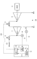
- FIG. 1 is a configuration diagram of an operation control apparatus for a steam turbine according to a first embodiment of the present invention.
- a steam turbine 101 to be controlled by the operation control device of the steam turbine of the present embodiment includes a high-pressure turbine 11 and a low-pressure turbine 12 as in the prior art, and the steam flow rate supplied to the high-pressure turbine 11 is determined.
- This is a configuration provided with a steam control valve 14 that adjusts and a bleed pressure regulating valve 15 that controls the flow rate of steam supplied from the high-pressure turbine 11 to the low-pressure turbine 12.
- the steam turbine 101 is connected to a generator 13 directly or via a gear.
- a speed detector 41 that detects the rotational speed of the steam turbine 110 and outputs a speed signal S1
- a bleed pressure of the steam turbine 110 that detects a bleed pressure and outputs a bleed pressure signal S2.
- An extraction pressure detector 42 and an extraction flow rate detector 43 that periodically detects the extraction flow rate of the steam turbine 110 and outputs an extraction flow rate signal S3 are provided.
- the electronic governor 21 as a steam turbine operation control device includes a speed controller 22 that generates a speed control output signal S11 based on an output target value of the steam turbine 101 and a speed signal S1 from the speed detector 41, and a steam turbine.
- the extraction pressure controller 23 In response to the extraction flow rate target value 101 and the extraction pressure signal S2 from the extraction pressure detector 42, the extraction pressure controller 23 generates the extraction pressure control output signal S12, and according to the speed control output signal S11 and the extraction pressure control output signal S12.
- a bleed map 24 for deriving the respective opening degrees of the steam control valve 14 and the bleed pressure regulating valve 15 at the determined operating point.
- the bleed map 24 is corrected based on the bleed flow signal S3 from the bleed flow detector 43 periodically (for example, at intervals of 1 [second]). That is, the scale of the extraction pressure control output signal in the extraction map 24 is multiplied by “extraction flow target value / extraction flow actual measurement value” times based on the extraction flow target value of the steam turbine 101 and the actual extraction flow actual value of the steam turbine 101 in the current operation control. To correct. This correction corrects the deviation between the actual machine and the assumption (plan).
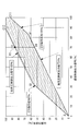
- FIG. 2 is an explanatory diagram illustrating an extraction map used in the operation control of the steam turbine of the present embodiment
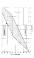
- FIG. 3 illustrates the relationship between the high-pressure steam flow corresponding to the extraction map (FIG. 2) and the turbine output.
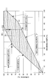
- FIG. 4 is an explanatory diagram illustrating a bleed map after correction in the present embodiment.
- the extraction map 24 has a horizontal axis as a speed control output signal [%] and a vertical axis as a GV operation signal [%] (opening degree of the steam control valve 14).
- the extraction pressure control output signal [%] from 0 [%] (: line segment O-A1 in the figure) to 100 [%] (: line segment B1-C12 in the figure)
- the scale is ticked in the vertical axis direction (indicated by the dot-and-dash line every 10 [%] in the figure), and the ECV operation signal [%] (opening of the bleed pressure regulating valve 15) is 0 [%] (: Middle, line segment O-B1) to 100 [%] (: line segment A1-C11 in the figure), with the scale in the horizontal axis direction (shown in broken lines every 10 [%] in the figure) is there.
- the speed control output signal [%] is the turbine output [MW]
- the GV operation signal [%] is the high-pressure steam flow rate [%]
- the extraction pressure control output signal [%] is the extraction flow rate [t / h].
- the correction of the extraction map 24 will be described by exemplifying a case where a deviation occurs between the actual machine and the assumption (plan).
- the extraction flow rate actual measurement value 60 [t / h] based on the extraction flow rate signal S3 from the extraction flow rate detector 43 (actually, it is unlikely that such a large deviation occurs) To make it easier to understand.)
- the scale of the extraction pressure control output signal in the extraction map 24 is corrected to “extraction flow target value / extraction flow actual measurement value ⁇ 1.33” times as shown in FIG.
- the corrected bleed map 24 corresponds to the relative relationship between the speed control output signal [%] and the GV operation signal [%], and the bleed pressure control output signal [%] is 0 [%] (: In the figure, the scale is engraved in the vertical axis direction from line segment O-A1) to 100 [%] (: line segment B2-C22 in the figure), and the ECV operation signal [%] is 0 [%] ( : From the line segment O-B2) to 100 [%] (: line segment A1-C11 in the figure), the scale is engraved in the horizontal axis direction.
- the bleed flow rate is 60 [t / h] due to the difference between the above and the assumption.
- the ECV operation signal S22 is set between 0 and 100 [%] in order to adjust the valve opening of the bleed pressure regulating valve 15 between 0 and 80 [%]. This is a case where the valve opening adjustment range of the bleed pressure regulating valve 15 is narrow (for example, 0 to 76 [%]). In this case, although the actual flow rate will be lower than expected due to the steam flow being deviated, it will be possible to bring it to the expected operating state by correcting the extraction map 24 in accordance with the actual flow rate. .
- the steam control valve 14 has at least the high-pressure turbine 11 and the low-pressure turbine 12, and adjusts the steam flow rate supplied to the high-pressure turbine 11.
- An operation control device and an operation control method for a steam turbine 101 including an extraction pressure regulating valve 15 for adjusting the flow rate of steam supplied from the high-pressure turbine 11 to the low-pressure turbine 12, and an output target of the steam turbine 101 by the speed controller 21.
- a speed control output signal S11 is generated based on the value and the speed detection value (S1) (speed control step), and the extraction pressure controller 23 extracts the extraction pressure based on the extraction flow target value and the extraction pressure detection value (S2) of the steam turbine 101.
- a control output signal S12 is generated (extraction pressure control step), a speed control output signal S11 and an extraction pressure control output signal Referring to the extraction map 24 for deriving the respective opening degrees of the steam control valve 14 and the extraction pressure regulating valve 15 at the operating point determined according to 12, the respective operation signals (S21 and S22) of the steam adjustment valve 14 and the extraction pressure adjustment valve 15 are referred to. ) (Operation signal generation step), the scale of the extraction pressure control output signal S12 in the extraction map 24 is set to “extraction flow target” based on the actual extraction flow actual value (S3) of the steam turbine 101 detected periodically. The extraction map 24 corrected to “value / extraction flow actual measurement value” times is used.
- the extraction map 24 is corrected based on the actual extraction value (S3) detected periodically, and the opening of the steam control valve 14 and the opening of the extraction pressure regulating valve 15 are determined based on the corrected extraction map 24. Therefore, the deviation between the operating point on the extraction map 24 used for operation control of the steam turbine 101 and the actual operating point can be corrected, and the operation according to the assumed operation control can be performed. The machine performance can be realized reliably.
- FIG. 5 is a block diagram of the operation control apparatus for the steam turbine according to the second embodiment of the present invention.
- the same reference numerals are given to the portions overlapping those in FIG. 1 (first embodiment) and FIG. 7 (conventional example).
- the steam turbine 102 to be controlled by the operation control device of the steam turbine of the present embodiment includes the high-pressure turbine 11 and the low-pressure turbine 12 and supplies the high-pressure turbine 11 as in the first embodiment.
- a steam control valve 14 for adjusting the steam flow rate and a bleed pressure regulating valve 15 for adjusting the steam flow rate supplied from the high-pressure turbine 11 to the low-pressure turbine 12 are provided.
- the steam turbine 102 is connected to a generator 13 directly or via a gear.
- a speed detector 41 that detects the rotational speed of the steam turbine 110 and outputs a speed signal S1
- a bleed pressure of the steam turbine 110 that detects a bleed pressure and outputs a bleed pressure signal S2.
- An extraction pressure detector 42 and an output detector 45 that periodically detects the output of the generator 13 and outputs an output signal S4 are provided.
- the electronic governor 31 as an operation control device for the steam turbine includes a speed controller 32 that generates a speed control output signal S11 based on the output target value of the steam turbine 102 and the speed signal S1 from the speed detector 41, and a steam turbine.
- a speed controller 32 that generates a speed control output signal S11 based on the output target value of the steam turbine 102 and the speed signal S1 from the speed detector 41, and a steam turbine.
- an extraction pressure controller 33 In response to the extraction flow rate target value 102 and the extraction pressure signal S2 from the extraction pressure detector 42, an extraction pressure controller 33 that generates an extraction pressure control output signal S12, and a speed control output signal S11 and an extraction pressure control output signal S12.
- a bleed map 34 for deriving the respective opening degrees of the steam control valve 14 and the bleed pressure regulating valve 15 at the determined operating point.
- the extraction map 34 is corrected based on the output signal S4 from the output detector 45 periodically (for example, at intervals of 1 [second]). That is, based on the output target value of the steam turbine 102 and the actual output value of the steam turbine 102 in the current operation control, the scale of the speed control output signal in the extraction map 34 is corrected to “output actual value / output target value” times. This correction corrects the deviation between the actual machine and the assumption (plan).
- FIG. 6 is an explanatory view illustrating a bleed map after correction in the present embodiment.
- the current operation control is performed based on the bleed map 34 shown in FIG. 2 as in the first embodiment, and the bleed map 34 is corrected due to a deviation between the actual machine and the assumption (plan).
- the scale of the speed control output signal in the extraction map 34 is corrected to “output actual measurement value / output target value ⁇ 0.96” times as shown in FIG.
- the corrected extraction map 34 corresponds to the relative relationship between the speed control output signal [%] and the GV operation signal [%], and the extraction pressure control output signal [%] is 0 [%] (: In the figure, the scale is engraved in the vertical axis direction from the line segment O-A3) to 100 [%] (: line segment B1-C32 in the figure), and the ECV operation signal [%] is 0 [%] ( : Scale is engraved in the horizontal axis direction from line segment O-B1) to 100 [%] (: line segment A3-C31 in the figure).
- the steam control valve 14 has at least the high-pressure turbine 11 and the low-pressure turbine 12, and adjusts the steam flow rate supplied to the high-pressure turbine 11.
- An operation control device and an operation control method for a steam turbine 102 including an extraction pressure regulating valve 15 for adjusting the flow rate of steam supplied from the high-pressure turbine 11 to the low-pressure turbine 12, and an output target of the steam turbine 102 by the speed controller 31.
- a speed control output signal S11 is generated based on the value and the speed detection value (S1) (speed control step), and the extraction pressure controller 33 extracts the extraction pressure based on the extraction flow target value and the extraction pressure detection value (S2) of the steam turbine 102.
- a control output signal S12 is generated (extraction pressure control step), a speed control output signal S11 and an extraction pressure control output signal 12, with reference to the bleed map 34 for deriving the respective opening degrees of the steam control valve 14 and the bleed pressure regulating valve 15 at the operating point determined according to 12, the respective operation signals (S21 and S22) ) (Operation signal generation step), the scale of the speed control output signal S11 in the extraction map 34 is determined based on the actual measured output value (S4) of the steam turbine 103 periodically detected. The extraction map 34 corrected to “target value” times is used.
- the extraction map 34 is corrected based on the actually measured output value (S4) detected periodically, and the opening degree of the steam control valve 14 and the opening degree of the extraction pressure regulating valve 15 are adjusted based on the corrected extraction map 34. Since the adjustment is performed, the deviation between the operation point on the extraction map 34 used for the operation control of the steam turbine 102 and the actual operation point can be corrected, and the operation according to the assumed operation control can be performed. The machine performance can be reliably realized.
- the generator is described as an example of the driven machine of the steam turbine.
- the driven machine may be a compressor, and may be a pump or a fan.
- an output signal of a torque meter provided on the turbine output shaft may be used instead of the output signal of the generator.
Landscapes
- Engineering & Computer Science (AREA)
- Mechanical Engineering (AREA)
- General Engineering & Computer Science (AREA)
- Chemical & Material Sciences (AREA)
- Combustion & Propulsion (AREA)
- Physics & Mathematics (AREA)
- Fluid Mechanics (AREA)
- Control Of Turbines (AREA)
Abstract
速度制御器(22)により蒸気タービン(101)の出力目標値及び速度検出値に基づき速度制御出力信号(S11)を生成し、抽気圧制御器(23)により蒸気タービン(101)の抽気流量目標値及び抽気圧力検出値に基づき抽気圧制御出力信号(S12)を生成し、速度制御出力信号(S11)及び抽気圧制御出力信号(S12)に応じて定まる運転点における蒸気加減弁(14)及び抽気調圧弁(15)のそれぞれの開度を導く抽気マップ(24)を参照して、蒸気加減弁(14)及び抽気調圧弁(15)のそれぞれの操作信号を生成する際に、定期的に検出される蒸気タービン(101)の抽気流量実測値に基づき、抽気マップ(24)における抽気圧制御出力信号(S12)のスケールを「抽気流量目標値/抽気流量実測値」倍に修正した抽気マップ(24)を用いる。
Description
本発明は蒸気タービンの運転制御装置及び運転制御方法に係り、特に、抽気マップに基づき弁開度制御信号を生成して運転制御を行う蒸気タービンの運転制御装置及び運転制御方法に関するものである。
蒸気タービンの中間段から蒸気を抽出し、これをプラント等のプロセス系へ供給して利用する抽気タービンが知られている(例えば、特開昭62-67209号公報等)。図7に、従来の蒸気タービン及びその周辺機器の構成を例示する。同図において、蒸気タービン110は、高圧タービン11及び低圧タービン12を備え、また、高圧タービン11に供給する蒸気流量を加減する蒸気加減弁14と、高圧タービン11から低圧タービン12に供給する蒸気流量を加減する抽気調圧弁15とを備えた構成である。なお、蒸気タービン110には、発電機13が直結されている。
また、蒸気タービンの運転制御装置として電子ガバナ51を備えており、電子ガバナ51は、蒸気タービン110の出力目標値並びに速度検出器41からの速度信号S1に基づき速度制御出力信号S11を生成する速度制御器52と、蒸気タービン110の抽気流量目標値並びに抽気圧検出器42からの抽気圧力信号S2に基づき抽気圧制御出力信号S12を生成する抽気圧制御器53と、速度制御出力信号S11及び抽気圧制御出力信号S12に応じて定まる運転点における蒸気加減弁14及び抽気調圧弁15のそれぞれの開度を導く抽気マップ54と、を備えた構成であり、抽気マップ54の変換によって蒸気加減弁14のGV操作信号S21並びに抽気調圧弁15のECV操作信号S22を生成している。
このように、従来技術においては、抽気マップ54に基づいて、蒸気タービン110の出力に相当する速度制御出力信号S11、並びに、蒸気タービン110の抽気流量に相当する抽気圧制御出力信号S12を、蒸気加減弁14の開度並びに抽気調圧弁15の開度に変換して運転制御を行っている。ここで、実機における蒸気加減弁14の開度並びに抽気調圧弁15の開度と、想定している蒸気タービン110の出力及び蒸気タービン110の抽気流量との関係において、実機と想定(計画)との間にずれがある場合には、想定している抽気マップ54上の運転点と実際の運転点とにずれが生じ、想定する運転制御通りに運転が行われずに実機が本来備えている機械性能が実現されないおそれがあるという事情があった。
本発明は、上記従来の事情に鑑みてなされたものであって、蒸気タービンの運転制御に用いる抽気マップ上の運転点と実際の運転点とのずれを修正して、想定する運転制御通りの運転を行うことができ、実機が本来備えている機械性能を実現し得る蒸気タービンの運転制御装置及び運転制御方法を提供することを目的としている。
上記課題を解決するため、本発明は以下の手段を採用する。
本発明の第一の態様に係る蒸気タービンの運転制御装置は、少なくとも高圧タービン及び低圧タービンを有し、前記高圧タービンに供給する蒸気流量を加減する蒸気加減弁と、前記高圧タービンから前記低圧タービンに供給する蒸気流量を加減する抽気調圧弁とを備えた蒸気タービンの運転制御装置であって、前記蒸気タービンの出力目標値並びに該蒸気タービンの速度検出値に基づき速度制御出力信号を生成する速度制御器と、前記蒸気タービンの抽気流量目標値並びに該蒸気タービンの抽気圧力検出値に基づき抽気圧制御出力信号を生成する抽気圧制御器と、前記速度制御出力信号及び前記抽気圧制御出力信号に応じて定まる運転点における前記蒸気加減弁及び前記抽気調圧弁のそれぞれの開度を導く抽気マップと、を有し、定期的に検出される前記蒸気タービンの抽気流量実測値に基づき、前記抽気マップにおける前記抽気圧制御出力信号のスケールを「抽気流量目標値/抽気流量実測値」倍に修正し、該修正後の抽気マップを参照して、前記蒸気加減弁及び前記抽気調圧弁のそれぞれの操作信号を生成するものである。
本発明の第一の態様に係る蒸気タービンの運転制御装置は、少なくとも高圧タービン及び低圧タービンを有し、前記高圧タービンに供給する蒸気流量を加減する蒸気加減弁と、前記高圧タービンから前記低圧タービンに供給する蒸気流量を加減する抽気調圧弁とを備えた蒸気タービンの運転制御装置であって、前記蒸気タービンの出力目標値並びに該蒸気タービンの速度検出値に基づき速度制御出力信号を生成する速度制御器と、前記蒸気タービンの抽気流量目標値並びに該蒸気タービンの抽気圧力検出値に基づき抽気圧制御出力信号を生成する抽気圧制御器と、前記速度制御出力信号及び前記抽気圧制御出力信号に応じて定まる運転点における前記蒸気加減弁及び前記抽気調圧弁のそれぞれの開度を導く抽気マップと、を有し、定期的に検出される前記蒸気タービンの抽気流量実測値に基づき、前記抽気マップにおける前記抽気圧制御出力信号のスケールを「抽気流量目標値/抽気流量実測値」倍に修正し、該修正後の抽気マップを参照して、前記蒸気加減弁及び前記抽気調圧弁のそれぞれの操作信号を生成するものである。
本発明の第一の態様によれば、定期的に検出される抽気流量実測値に基づき抽気マップを修正し、修正後の抽気マップに基づいて蒸気加減弁の開度並びに抽気調圧弁の開度を調整するので、蒸気タービンの運転制御に用いる抽気マップ上の運転点と実際の運転点とのずれを修正して、想定する運転制御通りの運転を行うことができ、実機が本来備えている機械性能を確実に実現することができる。
本発明の第一の態様の蒸気タービンの運転制御装置においては、定期的に検出される前記蒸気タービンの出力実測値に基づき、前記抽気マップにおける前記速度制御出力信号のスケールを「出力実測値/出力目標値」倍に修正し、該修正後の抽気マップを参照して、前記蒸気加減弁及び前記抽気調圧弁のそれぞれの操作信号を生成することが好ましい。
この構成によれば、さらに定期的に検出される出力実測値に基づき抽気マップを修正し、修正後の抽気マップに基づいて蒸気加減弁の開度並びに抽気調圧弁の開度を調整するので、蒸気タービンの運転制御に用いる抽気マップ上の運転点と実際の運転点とのずれを修正して、想定する運転制御通りの運転を行うことができ、実機が本来備えている機械性能をより確実に実現することができる。
また、本発明の第二の態様に係る蒸気タービンの運転制御装置は、少なくとも高圧タービン及び低圧タービンを有し、前記高圧タービンに供給する蒸気流量を加減する蒸気加減弁と、前記高圧タービンから前記低圧タービンに供給する蒸気流量を加減する抽気調圧弁とを備えた蒸気タービンの運転制御装置であって、前記蒸気タービンの出力目標値並びに該蒸気タービンの速度検出値に基づき速度制御出力信号を生成する速度制御器と、前記蒸気タービンの抽気流量目標値並びに該蒸気タービンの抽気圧力検出値に基づき抽気圧制御出力信号を生成する抽気圧制御器と、前記速度制御出力信号及び前記抽気圧制御出力信号に応じて定まる運転点における前記蒸気加減弁及び前記抽気調圧弁のそれぞれの開度を導く抽気マップと、を有し、定期的に検出される前記蒸気タービンの出力実測値に基づき、前記抽気マップにおける前記速度制御出力信号のスケールを「出力実測値/出力目標値」倍に修正し、該修正後の抽気マップを参照して、前記蒸気加減弁及び前記抽気調圧弁のそれぞれの操作信号を生成するものである。
本発明の第二の態様によれば、定期的に検出される出力実測値に基づき抽気マップを修正し、修正後の抽気マップに基づいて蒸気加減弁の開度並びに抽気調圧弁の開度を調整するので、蒸気タービンの運転制御に用いる抽気マップ上の運転点と実際の運転点とのずれを修正して、想定する運転制御通りの運転を行うことができ、実機が本来備えている機械性能を確実に実現することができる。
また、本発明の第三の態様に係る蒸気タービンの運転制御方法は、少なくとも高圧タービン及び低圧タービンを有し、前記高圧タービンに供給する蒸気流量を加減する蒸気加減弁と、前記高圧タービンから前記低圧タービンに供給する蒸気流量を加減する抽気調圧弁とを備えた蒸気タービンの運転制御方法であって、前記蒸気タービンの出力目標値並びに該蒸気タービンの速度検出値に基づき速度制御出力信号を生成する速度制御ステップと、前記蒸気タービンの抽気流量目標値並びに該蒸気タービンの抽気圧力検出値に基づき抽気圧制御出力信号を生成する抽気圧制御ステップと、前記速度制御出力信号及び前記抽気圧制御出力信号に応じて定まる運転点における前記蒸気加減弁及び前記抽気調圧弁のそれぞれの開度を導く抽気マップを参照して、該蒸気加減弁及び該抽気調圧弁のそれぞれの操作信号を生成する操作信号生成ステップと、を有し、定期的に検出される前記蒸気タービンの抽気流量実測値に基づき、前記抽気マップにおける前記抽気圧制御出力信号のスケールを「抽気流量目標値/抽気流量実測値」倍に修正するものである。
本発明の第三の態様によれば、定期的に検出される抽気流量実測値に基づき抽気マップを修正し、修正後の抽気マップに基づいて蒸気加減弁の開度並びに抽気調圧弁の開度を調整するので、蒸気タービンの運転制御に用いる抽気マップ上の運転点と実際の運転点とのずれを修正して、想定する運転制御通りの運転を行うことができ、実機が本来備えている機械性能を確実に実現することができる。
本発明の第三の態様の蒸気タービンの運転制御方法においては、定期的に検出される前記蒸気タービンの出力実測値に基づき、前記抽気マップにおける前記速度制御出力信号のスケールを「出力実測値/出力目標値」倍に修正することが好ましい。
この構成によれば、さらに定期的に検出される出力実測値に基づき抽気マップを修正し、修正後の抽気マップに基づいて蒸気加減弁の開度並びに抽気調圧弁の開度を調整するので、蒸気タービンの運転制御に用いる抽気マップ上の運転点と実際の運転点とのずれを修正して、想定する運転制御通りの運転を行うことができ、実機が本来備えている機械性能をより確実に実現することができる。
さらに、本発明の第四の態様に係る蒸気タービンの運転制御方法は、少なくとも高圧タービン及び低圧タービンを有し、前記高圧タービンに供給する蒸気流量を加減する蒸気加減弁と、前記高圧タービンから前記低圧タービンに供給する蒸気流量を加減する抽気調圧弁とを備えた蒸気タービンの運転制御方法であって、前記蒸気タービンの出力目標値並びに該蒸気タービンの速度検出値に基づき速度制御出力信号を生成する速度制御ステップと、前記蒸気タービンの抽気流量目標値並びに該蒸気タービンの抽気圧力検出値に基づき抽気圧制御出力信号を生成する抽気圧制御ステップと、前記速度制御出力信号及び前記抽気圧制御出力信号に応じて定まる運転点における前記蒸気加減弁及び前記抽気調圧弁のそれぞれの開度を導く抽気マップを参照して、該蒸気加減弁及び該抽気調圧弁のそれぞれの操作信号を生成する操作信号生成ステップと、を有し、定期的に検出される前記蒸気タービンの出力実測値に基づき、前記抽気マップにおける前記速度制御出力信号のスケールを「出力実測値/出力目標値」倍に修正するものである。
本発明の第四の態様によれば、定期的に検出される出力実測値に基づき抽気マップを修正し、修正後の抽気マップに基づいて蒸気加減弁の開度並びに抽気調圧弁の開度を調整するので、蒸気タービンの運転制御に用いる抽気マップ上の運転点と実際の運転点とのずれを修正して、想定する運転制御通りの運転を行うことができ、実機が本来備えている機械性能を確実に実現することができる。
本発明によれば、蒸気タービンの運転制御に用いる抽気マップ上の運転点と実際の運転点とのずれを修正して、想定する運転制御通りの運転を行うことができ、実機が本来備えている機械性能を確実に実現することができるという効果を奏する。
以下、本発明の蒸気タービンの運転制御装置及び運転制御方法の実施形態について、第1実施形態、第2実施形態の順に図面を参照して詳細に説明する。
〔第1実施形態〕
図1は本発明の第1実施形態に係る蒸気タービンの運転制御装置の構成図である。同図において、図7(従来例)と重複する部分には同一の符号を附する。
同図において、本実施形態の蒸気タービンの運転制御装置が制御対象とする蒸気タービン101は、従来と同様に、高圧タービン11及び低圧タービン12を備え、また、高圧タービン11に供給する蒸気流量を加減する蒸気加減弁14と、高圧タービン11から低圧タービン12に供給する蒸気流量を加減する抽気調圧弁15とを備えた構成である。また、この蒸気タービン101には、発電機13が直結またはギアを介して接続されている。さらに、各種物理量を検出する検出器として、蒸気タービン110の回転速度を検出して速度信号S1を出力する速度検出器41と、蒸気タービン110の抽気圧力を検出して抽気圧力信号S2を出力する抽気圧検出器42と、蒸気タービン110の抽気流量を定期的に検出して抽気流量信号S3を出力する抽気流量検出器43と、を備えている。
図1は本発明の第1実施形態に係る蒸気タービンの運転制御装置の構成図である。同図において、図7(従来例)と重複する部分には同一の符号を附する。
同図において、本実施形態の蒸気タービンの運転制御装置が制御対象とする蒸気タービン101は、従来と同様に、高圧タービン11及び低圧タービン12を備え、また、高圧タービン11に供給する蒸気流量を加減する蒸気加減弁14と、高圧タービン11から低圧タービン12に供給する蒸気流量を加減する抽気調圧弁15とを備えた構成である。また、この蒸気タービン101には、発電機13が直結またはギアを介して接続されている。さらに、各種物理量を検出する検出器として、蒸気タービン110の回転速度を検出して速度信号S1を出力する速度検出器41と、蒸気タービン110の抽気圧力を検出して抽気圧力信号S2を出力する抽気圧検出器42と、蒸気タービン110の抽気流量を定期的に検出して抽気流量信号S3を出力する抽気流量検出器43と、を備えている。
また、蒸気タービンの運転制御装置としての電子ガバナ21は、蒸気タービン101の出力目標値並びに速度検出器41からの速度信号S1に基づき速度制御出力信号S11を生成する速度制御器22と、蒸気タービン101の抽気流量目標値並びに抽気圧検出器42からの抽気圧力信号S2に基づき抽気圧制御出力信号S12を生成する抽気圧制御器23と、速度制御出力信号S11及び抽気圧制御出力信号S12に応じて定まる運転点における蒸気加減弁14及び抽気調圧弁15のそれぞれの開度を導く抽気マップ24と、を備えた構成であり、抽気マップ24の変換によって蒸気加減弁14のGV操作信号S21並びに抽気調圧弁15のECV操作信号S22を生成している。
ここで、抽気マップ24は、定期的に(例えば1[秒]間隔で)抽気流量検出器43からの抽気流量信号S3に基づき修正される。すなわち、現運転制御における蒸気タービン101の抽気流量目標値並びに蒸気タービン101の抽気流量実測値に基づき、抽気マップ24における抽気圧制御出力信号のスケールを「抽気流量目標値/抽気流量実測値」倍に修正する。この修正により実機と想定(計画)との間にずれが修正されることとなる。
次に、以上のような構成要素を備えた蒸気タービンの運転制御装置による運転制御方法について、図2~図4を参照して説明する。ここで、図2は本実施形態の蒸気タービンの運転制御で用いる抽気マップを例示する説明図であり、図3は抽気マップ(図2)に対応する高圧蒸気流量とタービン出力との関係を例示する説明図であり、図4は本実施形態における修正後の抽気マップを例示する説明図である。
まず、図2の抽気マップについて簡単に説明すると、抽気マップ24は、横軸を速度制御出力信号[%]、縦軸をGV操作信号[%](蒸気加減弁14の開度)とし、これらの相対関係に対応して、抽気圧制御出力信号[%]について、0[%](:図中、線分O-A1)から100[%](:図中、線分B1-C12)まで、縦軸方向にスケールを刻み(図中、1点鎖線で10[%]毎に表記)、またECV操作信号[%](抽気調圧弁15の開度)について、0[%](:図中、線分O-B1)から100[%](:図中、線分A1-C11)まで、横軸方向にスケールを刻んだもの(図中、破線で10[%]毎に表記)である。
例えば、速度制御器22から速度制御出力信号S11=70[%]が、また抽気圧制御器23から抽気圧制御出力信号S12=100[%]がそれぞれ出力されているとき、抽気マップ24上で運転点R1が定まり、該運転点R1における蒸気加減弁14の開度並びに抽気調圧弁15の開度が求められる。すなわち、GV操作信号S21=85[%]、ECV操作信号S22=46[%]である。
また、抽気マップにおける速度制御出力信号[%]はタービン出力[MW]に、GV操作信号[%]は高圧蒸気流量[%]に、抽気圧制御出力信号[%]は抽気流量[t/h]に、それぞれ対応しており、これらの関係は図3の制御マップで表される。なお、制御マップは、蒸気加減弁14の開度制御と抽気調圧弁15の開度制御とが干渉を起こさない不干渉制御となるよう、設計データ等に基づき作成されるものであり、蒸気タービンの運転制御時には、この制御マップを参照して蒸気タービン101の出力目標値及び抽気流量目標値が設定される。つまり、上記した具体的数値例では、蒸気タービン101の出力目標値=21[MW]、抽気流量目標値=80[t/h]に設定されていたこととなる。
次に、抽気マップ24の修正について、実機と想定(計画)との間にずれが生じているケースを例示して説明する。ここでは、抽気流量検出器43からの抽気流量信号S3により、抽気流量実測値=60[t/h]であったとする(実際には、これほどの大きなずれが生じる可能性は低いが、説明を分かり易くするためにこの数値例を用いる)。このとき、抽気マップ24における抽気圧制御出力信号のスケールは「抽気流量目標値/抽気流量実測値≒1.33」倍に修正され、図4に示す如くなる。
図4において、修正後の抽気マップ24は、速度制御出力信号[%]及びGV操作信号[%]の相対関係に対応して、抽気圧制御出力信号[%]について、0[%](:図中、線分O-A1)から100[%](:図中、線分B2-C22)まで、縦軸方向にスケールが刻まれ、またECV操作信号[%]について、0[%](:図中、線分O-B2)から100[%](:図中、線分A1-C11)まで、横軸方向にスケールが刻まれたものとなっている。
したがって、図2の抽気マップ24上では運転点がR1であったが、この修正により、図4の修正後の抽気マップ24上では運転点はR2となり、該運転点R2における蒸気加減弁14の開度並びに抽気調圧弁15の開度が求められ、GV操作信号S21=96[%]、ECV操作信号S22=32[%]となる。
すなわち、蒸気タービン101の出力目標値=21[MW]、抽気流量目標値=80[t/h]に応じて図2の抽気マップ24上での運転点R1による運転制御を行ったが、実機と想定との間のずれにより、実際には抽気流量=60[t/h]となっていた。ここで、図4の修正後の抽気マップ24上での運転点R2による運転制御を行うことにより、抽気流量=80[t/h]とすることが可能となる。
なお、実機と想定(計画)との間のずれは、例えば、蒸気加減弁14や抽気調圧弁15などについて起こり得る。より具体的には、抽気調圧弁15の弁開度を0~80[%]の間で調整するためにECV操作信号S22は0~100[%]の間で設定されるが、実際には抽気調圧弁15の弁開度調整範囲が狭いような(例えば、0~76[%])ケースである。この場合、実機では想定よりも蒸気流量が抑えられることとなってずれが生じるが、実機に即した抽気マップ24の修正を行うことにより、想定通りの運転状態に持っていくことが可能となる。
以上説明したように、本実施形態の蒸気タービンの運転制御装置及び運転制御方法では、少なくとも高圧タービン11及び低圧タービン12を有し、高圧タービン11に供給する蒸気流量を加減する蒸気加減弁14と、高圧タービン11から低圧タービン12に供給する蒸気流量を加減する抽気調圧弁15とを備えた蒸気タービン101の運転制御装置及び運転制御方法であって、速度制御器21により蒸気タービン101の出力目標値及び速度検出値(S1)に基づき速度制御出力信号S11を生成し(速度制御ステップ)、抽気圧制御器23により蒸気タービン101の抽気流量目標値及び抽気圧力検出値(S2)に基づき抽気圧制御出力信号S12を生成し(抽気圧制御ステップ)、速度制御出力信号S11及び抽気圧制御出力信号S12に応じて定まる運転点における蒸気加減弁14及び抽気調圧弁15のそれぞれの開度を導く抽気マップ24を参照して、蒸気加減弁14及び抽気調圧弁15のそれぞれの操作信号(S21及びS22)を生成する(操作信号生成ステップ)際に、定期的に検出される蒸気タービン101の抽気流量実測値(S3)に基づき、抽気マップ24における抽気圧制御出力信号S12のスケールを「抽気流量目標値/抽気流量実測値」倍に修正した抽気マップ24を用いる。
このように、定期的に検出される抽気流量実測値(S3)に基づき抽気マップ24を修正し、修正後の抽気マップ24に基づいて蒸気加減弁14の開度並びに抽気調圧弁15の開度を調整するので、蒸気タービン101の運転制御に用いる抽気マップ24上の運転点と実際の運転点とのずれを修正して、想定する運転制御通りの運転を行うことができ、実機が本来備えている機械性能を確実に実現することができる。
〔第2実施形態〕
次に、図5は本発明の第2実施形態に係る蒸気タービンの運転制御装置の構成図である。同図において、図1(第1実施形態)及び図7(従来例)と重複する部分には同一の符号を附する。
次に、図5は本発明の第2実施形態に係る蒸気タービンの運転制御装置の構成図である。同図において、図1(第1実施形態)及び図7(従来例)と重複する部分には同一の符号を附する。
同図において、本実施形態の蒸気タービンの運転制御装置が制御対象とする蒸気タービン102は、第1実施形態と同様に、高圧タービン11及び低圧タービン12を備え、また、高圧タービン11に供給する蒸気流量を加減する蒸気加減弁14と、高圧タービン11から低圧タービン12に供給する蒸気流量を加減する抽気調圧弁15とを備えた構成である。また、この蒸気タービン102には、発電機13が直結またはギアを介して接続されている。さらに、各種物理量を検出する検出器として、蒸気タービン110の回転速度を検出して速度信号S1を出力する速度検出器41と、蒸気タービン110の抽気圧力を検出して抽気圧力信号S2を出力する抽気圧検出器42と、発電機13の出力を定期的に検出して出力信号S4を出力する出力検出器45と、を備えている。
また、蒸気タービンの運転制御装置としての電子ガバナ31は、蒸気タービン102の出力目標値並びに速度検出器41からの速度信号S1に基づき速度制御出力信号S11を生成する速度制御器32と、蒸気タービン102の抽気流量目標値並びに抽気圧検出器42からの抽気圧力信号S2に基づき抽気圧制御出力信号S12を生成する抽気圧制御器33と、速度制御出力信号S11及び抽気圧制御出力信号S12に応じて定まる運転点における蒸気加減弁14及び抽気調圧弁15のそれぞれの開度を導く抽気マップ34と、を備えた構成であり、抽気マップ34の変換によって蒸気加減弁14のGV操作信号S21並びに抽気調圧弁15のECV操作信号S22を生成している。
ここで、抽気マップ34は、定期的に(例えば1[秒]間隔で)出力検出器45からの出力信号S4に基づき修正される。すなわち、現運転制御における蒸気タービン102の出力目標値並びに蒸気タービン102の出力実測値に基づき、抽気マップ34における速度制御出力信号のスケールを「出力実測値/出力目標値」倍に修正する。この修正により実機と想定(計画)との間にずれが修正されることとなる。
次に、以上のような構成要素を備えた蒸気タービンの運転制御装置による運転制御方法について、図2及び図6を参照して説明する。ここで、図6は本実施形態における修正後の抽気マップを例示する説明図である。
ここで、現運転制御が第1実施形態同様に図2に示す抽気マップ34に基づき行われているものとし、実機と想定(計画)との間にずれが生じて抽気マップ34を修正するケースを例示して説明する。すなわち、出力検出器45からの出力信号S4により、出力実測値=21×0.96=20.16≒20.2[MW]であったとする。
このとき、抽気マップ34における速度制御出力信号のスケールは「出力実測値/出力目標値≒0.96」倍に修正され、図6に示す如くなる。
このとき、抽気マップ34における速度制御出力信号のスケールは「出力実測値/出力目標値≒0.96」倍に修正され、図6に示す如くなる。
図6において、修正後の抽気マップ34は、速度制御出力信号[%]及びGV操作信号[%]の相対関係に対応して、抽気圧制御出力信号[%]について、0[%](:図中、線分O-A3)から100[%](:図中、線分B1-C32)まで、縦軸方向にスケールが刻まれ、またECV操作信号[%]について、0[%](:図中、線分O-B1)から100[%](:図中、線分A3-C31)まで、横軸方向にスケールが刻まれたものとなっている。
したがって、図2の抽気マップ24上では運転点がR1であったが、この修正により、図6の修正後の抽気マップ34上では運転点はR4となり、該運転点R4における蒸気加減弁14の開度並びに抽気調圧弁15の開度が求められ、GV操作信号S21=88[%]、ECV操作信号S22=47[%]となる。
すなわち、蒸気タービン102の出力目標値=24[MW]、抽気流量目標値=80[t/h]に応じて図2の抽気マップ34上での運転点R1による運転制御を行ったが、実機と想定との間のずれにより、実際には出力=20.2[MW]となっていた。ここで、図6の修正後の抽気マップ34上での運転点R4による運転制御を行うことにより、出力=21[MW]とすることが可能となる。
以上説明したように、本実施形態の蒸気タービンの運転制御装置及び運転制御方法では、少なくとも高圧タービン11及び低圧タービン12を有し、高圧タービン11に供給する蒸気流量を加減する蒸気加減弁14と、高圧タービン11から低圧タービン12に供給する蒸気流量を加減する抽気調圧弁15とを備えた蒸気タービン102の運転制御装置及び運転制御方法であって、速度制御器31により蒸気タービン102の出力目標値及び速度検出値(S1)に基づき速度制御出力信号S11を生成し(速度制御ステップ)、抽気圧制御器33により蒸気タービン102の抽気流量目標値及び抽気圧力検出値(S2)に基づき抽気圧制御出力信号S12を生成し(抽気圧制御ステップ)、速度制御出力信号S11及び抽気圧制御出力信号S12に応じて定まる運転点における蒸気加減弁14及び抽気調圧弁15のそれぞれの開度を導く抽気マップ34を参照して、蒸気加減弁14及び抽気調圧弁15のそれぞれの操作信号(S21及びS22)を生成する(操作信号生成ステップ)際に、定期的に検出される蒸気タービン103の出力実測値(S4)に基づき、抽気マップ34における速度制御出力信号S11のスケールを「出力実測値/出力目標値」倍に修正した抽気マップ34を用いる。
このように、定期的に検出される出力実測値(S4)に基づき抽気マップ34を修正し、修正後の抽気マップ34に基づいて蒸気加減弁14の開度並びに抽気調圧弁15の開度を調整するので、蒸気タービン102の運転制御に用いる抽気マップ34上の運転点と実際の運転点とのずれを修正して、想定する運転制御通りの運転を行うことができ、実機が本来備えている機械性能を確実に実現することができる。
以上、本発明の実施形態について図面を参照して詳述したが、本発明はこれら実施形態およびその変形に限定されるものではなく、本発明の要旨を逸脱しない範囲の設計変更等があっても本発明に含まれる。例えば、第1実施形態と第2実施形態を組み合わせた構成とすることができる。すなわち。第1実施形態の構成(図1)に、発電機13の出力を定期的に検出して出力信号S4を出力する出力検出器45を追加して、抽気マップ24を抽気流量検出器43からの抽気流量信号S3に基づき修正すると共に、出力検出器45からの出力信号S4に基づき修正する。なお、修正の順序は不問である。このようにすれば、蒸気タービンの運転制御に用いる抽気マップ上の運転点と実際の運転点とのずれを修正して、想定する運転制御通りの運転を行うことができ、実機が本来備えている機械性能をより確実に実現することができる。
また、上述した各実施形態では、蒸気タービンの被駆動機として発電機を例に挙げて説明したが、被駆動機としては、圧縮機としてもよく、さらにはポンプやファンであってもよい。第2実施形態において発電機が被駆動機とされていない場合には、発電機の出力信号に代えてタービン出力軸に装備したトルクメータの出力信号を用いれば良い。
また、上述した各実施形態では、蒸気タービンの被駆動機として発電機を例に挙げて説明したが、被駆動機としては、圧縮機としてもよく、さらにはポンプやファンであってもよい。第2実施形態において発電機が被駆動機とされていない場合には、発電機の出力信号に代えてタービン出力軸に装備したトルクメータの出力信号を用いれば良い。
11 高圧タービン
12 低圧タービン
13 発電機
14 蒸気加減弁
15 抽気調圧弁
21,31 電子ガバナ(蒸気タービンの運転制御装置)
22,32 速度制御器
23,33 抽気圧制御器
24,34 抽気マップ
41 速度検出器
42 抽気圧検出器
43 抽気流量検出器
101,102 蒸気タービン
12 低圧タービン
13 発電機
14 蒸気加減弁
15 抽気調圧弁
21,31 電子ガバナ(蒸気タービンの運転制御装置)
22,32 速度制御器
23,33 抽気圧制御器
24,34 抽気マップ
41 速度検出器
42 抽気圧検出器
43 抽気流量検出器
101,102 蒸気タービン
Claims (6)
- 少なくとも高圧タービン及び低圧タービンを有し、前記高圧タービンに供給する蒸気流量を加減する蒸気加減弁と、前記高圧タービンから前記低圧タービンに供給する蒸気流量を加減する抽気調圧弁とを備えた蒸気タービンの運転制御装置であって、
前記蒸気タービンの出力目標値並びに該蒸気タービンの速度検出値に基づき速度制御出力信号を生成する速度制御器と、
前記蒸気タービンの抽気流量目標値並びに該蒸気タービンの抽気圧力検出値に基づき抽気圧制御出力信号を生成する抽気圧制御器と、
前記速度制御出力信号及び前記抽気圧制御出力信号に応じて定まる運転点における前記蒸気加減弁及び前記抽気調圧弁のそれぞれの開度を導く抽気マップと、を有し、
定期的に検出される前記蒸気タービンの抽気流量実測値に基づき、前記抽気マップにおける前記抽気圧制御出力信号のスケールを「抽気流量目標値/抽気流量実測値」倍に修正し、該修正後の抽気マップを参照して、前記蒸気加減弁及び前記抽気調圧弁のそれぞれの操作信号を生成する蒸気タービンの運転制御装置。 - 定期的に検出される前記蒸気タービンの出力実測値に基づき、前記抽気マップにおける前記速度制御出力信号のスケールを「出力実測値/出力目標値」倍に修正し、該修正後の抽気マップを参照して、前記蒸気加減弁及び前記抽気調圧弁のそれぞれの操作信号を生成する請求項1に記載の蒸気タービンの運転制御装置。
- 少なくとも高圧タービン及び低圧タービンを有し、前記高圧タービンに供給する蒸気流量を加減する蒸気加減弁と、前記高圧タービンから前記低圧タービンに供給する蒸気流量を加減する抽気調圧弁とを備えた蒸気タービンの運転制御装置であって、
前記蒸気タービンの出力目標値並びに該蒸気タービンの速度検出値に基づき速度制御出力信号を生成する速度制御器と、
前記蒸気タービンの抽気流量目標値並びに該蒸気タービンの抽気圧力検出値に基づき抽気圧制御出力信号を生成する抽気圧制御器と、
前記速度制御出力信号及び前記抽気圧制御出力信号に応じて定まる運転点における前記蒸気加減弁及び前記抽気調圧弁のそれぞれの開度を導く抽気マップと、を有し、
定期的に検出される前記蒸気タービンの出力実測値に基づき、前記抽気マップにおける前記速度制御出力信号のスケールを「出力実測値/出力目標値」倍に修正し、該修正後の抽気マップを参照して、前記蒸気加減弁及び前記抽気調圧弁のそれぞれの操作信号を生成する蒸気タービンの運転制御装置。 - 少なくとも高圧タービン及び低圧タービンを有し、前記高圧タービンに供給する蒸気流量を加減する蒸気加減弁と、前記高圧タービンから前記低圧タービンに供給する蒸気流量を加減する抽気調圧弁とを備えた蒸気タービンの運転制御方法であって、
前記蒸気タービンの出力目標値並びに該蒸気タービンの速度検出値に基づき速度制御出力信号を生成する速度制御ステップと、
前記蒸気タービンの抽気流量目標値並びに該蒸気タービンの抽気圧力検出値に基づき抽気圧制御出力信号を生成する抽気圧制御ステップと、
前記速度制御出力信号及び前記抽気圧制御出力信号に応じて定まる運転点における前記蒸気加減弁及び前記抽気調圧弁のそれぞれの開度を導く抽気マップを参照して、該蒸気加減弁及び該抽気調圧弁のそれぞれの操作信号を生成する操作信号生成ステップと、を有し、
定期的に検出される前記蒸気タービンの抽気流量実測値に基づき、前記抽気マップにおける前記抽気圧制御出力信号のスケールを「抽気流量目標値/抽気流量実測値」倍に修正する蒸気タービンの運転制御方法。 - 定期的に検出される前記蒸気タービンの出力実測値に基づき、前記抽気マップにおける前記速度制御出力信号のスケールを「出力実測値/出力目標値」倍に修正する請求項4に記載の蒸気タービンの運転制御方法。
- 少なくとも高圧タービン及び低圧タービンを有し、前記高圧タービンに供給する蒸気流量を加減する蒸気加減弁と、前記高圧タービンから前記低圧タービンに供給する蒸気流量を加減する抽気調圧弁とを備えた蒸気タービンの運転制御方法であって、
前記蒸気タービンの出力目標値並びに該蒸気タービンの速度検出値に基づき速度制御出力信号を生成する速度制御ステップと、
前記蒸気タービンの抽気流量目標値並びに該蒸気タービンの抽気圧力検出値に基づき抽気圧制御出力信号を生成する抽気圧制御ステップと、
前記速度制御出力信号及び前記抽気圧制御出力信号に応じて定まる運転点における前記蒸気加減弁及び前記抽気調圧弁のそれぞれの開度を導く抽気マップを参照して、該蒸気加減弁及び該抽気調圧弁のそれぞれの操作信号を生成する操作信号生成ステップと、を有し、
定期的に検出される前記蒸気タービンの出力実測値に基づき、前記抽気マップにおける前記速度制御出力信号のスケールを「出力実測値/出力目標値」倍に修正する蒸気タービンの運転制御方法。
Priority Applications (2)
| Application Number | Priority Date | Filing Date | Title |
|---|---|---|---|
| CN201180057168.0A CN103228873B (zh) | 2011-02-25 | 2011-07-25 | 蒸气涡轮的运转控制装置及运转控制方法 |
| US13/989,992 US9371740B2 (en) | 2011-02-25 | 2011-07-25 | Operation control apparatus and operation control method for steam turbine |
Applications Claiming Priority (2)
| Application Number | Priority Date | Filing Date | Title |
|---|---|---|---|
| JP2011-040724 | 2011-02-25 | ||
| JP2011040724A JP5595306B2 (ja) | 2011-02-25 | 2011-02-25 | 蒸気タービンの運転制御装置及び運転制御方法 |
Publications (1)
| Publication Number | Publication Date |
|---|---|
| WO2012114557A1 true WO2012114557A1 (ja) | 2012-08-30 |
Family
ID=46720363
Family Applications (1)
| Application Number | Title | Priority Date | Filing Date |
|---|---|---|---|
| PCT/JP2011/066820 Ceased WO2012114557A1 (ja) | 2011-02-25 | 2011-07-25 | 蒸気タービンの運転制御装置及び運転制御方法 |
Country Status (4)
| Country | Link |
|---|---|
| US (1) | US9371740B2 (ja) |
| JP (1) | JP5595306B2 (ja) |
| CN (1) | CN103228873B (ja) |
| WO (1) | WO2012114557A1 (ja) |
Families Citing this family (13)
| Publication number | Priority date | Publication date | Assignee | Title |
|---|---|---|---|---|
| CN105134312B (zh) * | 2015-08-17 | 2016-10-26 | 西安西热节能技术有限公司 | 一种亚临界喷嘴配汽汽轮机运行阀位确定方法 |
| US9856796B2 (en) * | 2015-12-07 | 2018-01-02 | General Electric Company | Application of probabilistic control in gas turbine tuning for power output-emissions parameters with scaling factor, related control systems, computer program products and methods |
| US9879615B2 (en) * | 2015-12-16 | 2018-01-30 | General Electric Company | Machine-specific probabilistic control in gas turbine tuning for power output-emissions parameters, related control systems, computer program products and methods |
| US9879614B2 (en) * | 2015-12-16 | 2018-01-30 | General Electric Company | Machine-specific combined probabilistic control in gas turbine tuning for power output-emissions parameters with scaling factor, related control systems, computer program products and methods |
| US9879612B2 (en) * | 2015-12-16 | 2018-01-30 | General Electric Company | Combined probabilistic control in gas turbine tuning for power output-emissions parameters with scaling factor, related control systems, computer program products and methods |
| US9797315B2 (en) * | 2015-12-16 | 2017-10-24 | General Electric Company | Probabilistic control in gas turbine tuning for power output-emissions parameters, related control systems, computer program products and methods |
| US9879613B2 (en) * | 2015-12-16 | 2018-01-30 | General Electric Company | Application of combined probabilistic control in gas turbine tuning for power output-emissions parameters with scaling factor, related control systems, computer program products and methods |
| US9856797B2 (en) * | 2015-12-16 | 2018-01-02 | General Electric Company | Application of combined probabilistic control in gas turbine tuning for power output-emissions parameters with scaling factor, related control systems, computer program products and methods |
| CN106500173B (zh) * | 2016-10-26 | 2019-11-29 | 河南华润电力首阳山有限公司 | 火电厂抽汽供热的控制方法及控制系统 |
| CN108240238B (zh) * | 2016-12-26 | 2020-11-24 | 上海电气电站设备有限公司 | 抽汽背压给水泵汽轮机的控制系统及控制方法、汽轮机 |
| US10260377B2 (en) | 2017-02-03 | 2019-04-16 | Woodward, Inc. | Generating steam turbine performance maps |
| EP3553286B1 (en) | 2017-02-10 | 2021-07-07 | Mitsubishi Heavy Industries Compressor Corporation | Steam turbine, partition member, and method for operating steam turbine |
| CN116403749A (zh) * | 2023-03-02 | 2023-07-07 | 山东核电有限公司 | 核电站堆机协调控制方法及其装置 |
Citations (3)
| Publication number | Priority date | Publication date | Assignee | Title |
|---|---|---|---|---|
| JPS55146205A (en) * | 1979-05-01 | 1980-11-14 | Toshiba Corp | Control system for condensing extraction turbine |
| JPS6267209A (ja) * | 1985-09-20 | 1987-03-26 | Mitsubishi Heavy Ind Ltd | 蒸気タ−ビン用電子式ガバナ |
| JPH0539703A (ja) * | 1991-08-06 | 1993-02-19 | Fuji Electric Co Ltd | 蒸気タービン発電設備 |
Family Cites Families (15)
| Publication number | Priority date | Publication date | Assignee | Title |
|---|---|---|---|---|
| US4245162A (en) * | 1973-08-15 | 1981-01-13 | Westinghouse Electric Corp. | Steam turbine power plant having improved testing method and system for turbine inlet valves associated with downstream inlet valves preferably having feedforward position managed control |
| US4057715A (en) * | 1973-11-06 | 1977-11-08 | Westinghouse Electric Corporation | Wide range system for transferring steam generator and turbine operation between computers in a multiple turbine computer control system |
| US4220869A (en) * | 1974-03-08 | 1980-09-02 | Westinghouse Electric Corp. | Digital computer system and method for operating a steam turbine with efficient control mode selection |
| US4471446A (en) * | 1982-07-12 | 1984-09-11 | Westinghouse Electric Corp. | Control system and method for a steam turbine having a steam bypass arrangement |
| US4474012A (en) * | 1983-07-13 | 1984-10-02 | General Electric Company | Steam turbine pressure rate limiter |
| US4577281A (en) * | 1983-12-16 | 1986-03-18 | Westinghouse Electric Corp. | Method and apparatus for controlling the control valve setpoint mode selection for an extraction steam turbine |
| US4788647A (en) * | 1986-09-24 | 1988-11-29 | Digitek, Inc. | Control system for electric power plant |
| US4888954A (en) * | 1989-03-30 | 1989-12-26 | Westinghouse Electric Corp. | Method for heat rate improvement in partial-arc steam turbine |
| KR0152445B1 (ko) * | 1990-01-25 | 1998-10-01 | 고든 에이치. 텔퍼 | 밸브의 동작 특성을 평가하는 진단 시스템 및 방법 |
| US4976108A (en) * | 1990-05-11 | 1990-12-11 | Westinghouse Electric Corp. | Turbine efficient valve position computer |
| DE4124678A1 (de) * | 1990-08-21 | 1992-02-27 | Abb Patent Gmbh | Verfahren und einrichtung zur wiederherstellung der turbinenstellreserve nach dem ausregeln einer leistungs-sollwertaenderung in einem dampfkraftwerksblock |
| JP2003301935A (ja) * | 2002-04-05 | 2003-10-24 | Toyota Motor Corp | 無段変速機の制御装置 |
| JP2006090287A (ja) | 2004-09-27 | 2006-04-06 | Mitsubishi Heavy Ind Ltd | 複合発電システム及び燃料ガス発熱量制御方法 |
| JP2010008121A (ja) * | 2008-06-25 | 2010-01-14 | Denso Corp | センサ出力処理装置及びセンサ出力処理システム |
| US8197182B2 (en) * | 2008-12-23 | 2012-06-12 | General Electric Company | Opposed flow high pressure-low pressure steam turbine |
-
2011
- 2011-02-25 JP JP2011040724A patent/JP5595306B2/ja not_active Expired - Fee Related
- 2011-07-25 CN CN201180057168.0A patent/CN103228873B/zh not_active Expired - Fee Related
- 2011-07-25 WO PCT/JP2011/066820 patent/WO2012114557A1/ja not_active Ceased
- 2011-07-25 US US13/989,992 patent/US9371740B2/en not_active Expired - Fee Related
Patent Citations (3)
| Publication number | Priority date | Publication date | Assignee | Title |
|---|---|---|---|---|
| JPS55146205A (en) * | 1979-05-01 | 1980-11-14 | Toshiba Corp | Control system for condensing extraction turbine |
| JPS6267209A (ja) * | 1985-09-20 | 1987-03-26 | Mitsubishi Heavy Ind Ltd | 蒸気タ−ビン用電子式ガバナ |
| JPH0539703A (ja) * | 1991-08-06 | 1993-02-19 | Fuji Electric Co Ltd | 蒸気タービン発電設備 |
Also Published As
| Publication number | Publication date |
|---|---|
| JP5595306B2 (ja) | 2014-09-24 |
| CN103228873A (zh) | 2013-07-31 |
| US20130243574A1 (en) | 2013-09-19 |
| JP2012177340A (ja) | 2012-09-13 |
| CN103228873B (zh) | 2015-03-25 |
| US9371740B2 (en) | 2016-06-21 |
Similar Documents
| Publication | Publication Date | Title |
|---|---|---|
| JP5595306B2 (ja) | 蒸気タービンの運転制御装置及び運転制御方法 | |
| US20220195947A1 (en) | Two-shaft gas turbine control system and method | |
| US9932850B2 (en) | Correction system and method for gas turbine proportional droop governor | |
| CN101126352B (zh) | 用于燃气轮机控制的系统及其方法 | |
| US8304926B2 (en) | Wind turbine sound management | |
| US7053341B2 (en) | Method and apparatus for drum level control for drum-type boilers | |
| JP2018185803A (ja) | 動作信頼度および動作異常に基づき発電システムを制御する制御システムおよび方法 | |
| EP1939431A2 (en) | Methods and apparatus to facilitate gas turbine fuel control | |
| CN112765796B (zh) | 一种双馈风机轴系扭振抑制分析方法及系统 | |
| KR101778912B1 (ko) | 풍력발전기의 요 정렬오차 보정장치 | |
| CN104727947B (zh) | 燃气涡轮焚烧温度控制系统和方法 | |
| JP2011252686A (ja) | 燃料供給システム | |
| CN106232963A (zh) | 燃气涡轮的燃料控制方法、执行该方法的控制装置、以及具备该控制装置的燃气涡轮设备 | |
| US20230314130A1 (en) | Method for detecting a blade misalignment of a rotor blade of a rotor of a wind turbine | |
| WO2014003166A1 (ja) | 原子炉出力調整装置 | |
| US10260378B2 (en) | Systems and methods for controlling flow valves in a turbine | |
| TW202327231A (zh) | 伺服電機及其編碼器校正方法 | |
| JP2012077617A (ja) | 発電プラントおよび発電プラント制御装置 | |
| KR20230101091A (ko) | 발전소의 터빈 제어 밸브 자동 교정 시스템 및 발전소의 터빈 제어 밸브(300) 교정 방법 | |
| JP4908465B2 (ja) | コンバインド制御装置 | |
| JP2006009732A (ja) | タービン制御装置およびタービン制御装置の弁開度指令補正方法 | |
| KR102826834B1 (ko) | 가스 터빈의 출력 수정 방법, 제어 방법, 이들 방법을 실행하는 장치, 및 이들 방법을 컴퓨터에 실행시키는 프로그램 | |
| CN121954464A (zh) | 汽轮机阀门的试验方法、装置、存储介质及计算机设备 | |
| WO2019012814A1 (ja) | 風力発電装置、風力発電装置の制御方法、および風力発電システム | |
| JPH10122120A (ja) | 水車及びポンプ水車の調速制御装置並びにそれらの調速制御方法 |
Legal Events
| Date | Code | Title | Description |
|---|---|---|---|
| 121 | Ep: the epo has been informed by wipo that ep was designated in this application |
Ref document number: 11859029 Country of ref document: EP Kind code of ref document: A1 |
|
| WWE | Wipo information: entry into national phase |
Ref document number: 13989992 Country of ref document: US |
|
| NENP | Non-entry into the national phase |
Ref country code: DE |
|
| 122 | Ep: pct application non-entry in european phase |
Ref document number: 11859029 Country of ref document: EP Kind code of ref document: A1 |