WO2012111767A1 - 音声復号装置、音声符号化装置、音声復号方法、音声符号化方法、音声復号プログラム、及び音声符号化プログラム - Google Patents
音声復号装置、音声符号化装置、音声復号方法、音声符号化方法、音声復号プログラム、及び音声符号化プログラム Download PDFInfo
- Publication number
- WO2012111767A1 WO2012111767A1 PCT/JP2012/053700 JP2012053700W WO2012111767A1 WO 2012111767 A1 WO2012111767 A1 WO 2012111767A1 JP 2012053700 W JP2012053700 W JP 2012053700W WO 2012111767 A1 WO2012111767 A1 WO 2012111767A1
- Authority
- WO
- WIPO (PCT)
- Prior art keywords
- frequency band
- time envelope
- envelope
- low frequency
- high frequency
- Prior art date
Links
Images


Classifications
-
- G—PHYSICS
- G10—MUSICAL INSTRUMENTS; ACOUSTICS
- G10L—SPEECH ANALYSIS OR SYNTHESIS; SPEECH RECOGNITION; SPEECH OR VOICE PROCESSING; SPEECH OR AUDIO CODING OR DECODING
- G10L21/00—Processing of the speech or voice signal to produce another audible or non-audible signal, e.g. visual or tactile, in order to modify its quality or its intelligibility
- G10L21/02—Speech enhancement, e.g. noise reduction or echo cancellation
- G10L21/038—Speech enhancement, e.g. noise reduction or echo cancellation using band spreading techniques
-
- G—PHYSICS
- G10—MUSICAL INSTRUMENTS; ACOUSTICS
- G10L—SPEECH ANALYSIS OR SYNTHESIS; SPEECH RECOGNITION; SPEECH OR VOICE PROCESSING; SPEECH OR AUDIO CODING OR DECODING
- G10L19/00—Speech or audio signals analysis-synthesis techniques for redundancy reduction, e.g. in vocoders; Coding or decoding of speech or audio signals, using source filter models or psychoacoustic analysis
- G10L19/02—Speech or audio signals analysis-synthesis techniques for redundancy reduction, e.g. in vocoders; Coding or decoding of speech or audio signals, using source filter models or psychoacoustic analysis using spectral analysis, e.g. transform vocoders or subband vocoders
-
- G—PHYSICS
- G10—MUSICAL INSTRUMENTS; ACOUSTICS
- G10L—SPEECH ANALYSIS OR SYNTHESIS; SPEECH RECOGNITION; SPEECH OR VOICE PROCESSING; SPEECH OR AUDIO CODING OR DECODING
- G10L19/00—Speech or audio signals analysis-synthesis techniques for redundancy reduction, e.g. in vocoders; Coding or decoding of speech or audio signals, using source filter models or psychoacoustic analysis
- G10L19/04—Speech or audio signals analysis-synthesis techniques for redundancy reduction, e.g. in vocoders; Coding or decoding of speech or audio signals, using source filter models or psychoacoustic analysis using predictive techniques
- G10L19/26—Pre-filtering or post-filtering
-
- G—PHYSICS
- G10—MUSICAL INSTRUMENTS; ACOUSTICS
- G10L—SPEECH ANALYSIS OR SYNTHESIS; SPEECH RECOGNITION; SPEECH OR VOICE PROCESSING; SPEECH OR AUDIO CODING OR DECODING
- G10L21/00—Processing of the speech or voice signal to produce another audible or non-audible signal, e.g. visual or tactile, in order to modify its quality or its intelligibility
- G10L21/02—Speech enhancement, e.g. noise reduction or echo cancellation
- G10L21/038—Speech enhancement, e.g. noise reduction or echo cancellation using band spreading techniques
- G10L21/0388—Details of processing therefor
-
- G—PHYSICS
- G10—MUSICAL INSTRUMENTS; ACOUSTICS
- G10L—SPEECH ANALYSIS OR SYNTHESIS; SPEECH RECOGNITION; SPEECH OR VOICE PROCESSING; SPEECH OR AUDIO CODING OR DECODING
- G10L25/00—Speech or voice analysis techniques not restricted to a single one of groups G10L15/00 - G10L21/00
- G10L25/03—Speech or voice analysis techniques not restricted to a single one of groups G10L15/00 - G10L21/00 characterised by the type of extracted parameters
- G10L25/18—Speech or voice analysis techniques not restricted to a single one of groups G10L15/00 - G10L21/00 characterised by the type of extracted parameters the extracted parameters being spectral information of each sub-band
-
- G—PHYSICS
- G10—MUSICAL INSTRUMENTS; ACOUSTICS
- G10L—SPEECH ANALYSIS OR SYNTHESIS; SPEECH RECOGNITION; SPEECH OR VOICE PROCESSING; SPEECH OR AUDIO CODING OR DECODING
- G10L25/00—Speech or voice analysis techniques not restricted to a single one of groups G10L15/00 - G10L21/00
- G10L25/03—Speech or voice analysis techniques not restricted to a single one of groups G10L15/00 - G10L21/00 characterised by the type of extracted parameters
- G10L25/21—Speech or voice analysis techniques not restricted to a single one of groups G10L15/00 - G10L21/00 characterised by the type of extracted parameters the extracted parameters being power information
Definitions
- the present invention relates to a speech decoding device, a speech encoding device, a speech decoding method, a speech encoding method, a speech decoding program, and a speech encoding program.
- Audio-acoustic coding technology that compresses the amount of signal data to tens of ones by removing information unnecessary for human perception using auditory psychology is a very important technology in signal transmission and storage.
- MPEG4 AAC Advanced Audio
- ISO / IEC MPEG Moving Picture Experts Group
- a band expansion technique for generating a high-frequency component using a low-frequency component of speech has been widely used in recent years.
- a typical example of this bandwidth expansion technology is SBR (Spectral Band Replication) technology used in MPEG4 AAC.
- QMF Quadrature Mirror Filter
- the high frequency component is adjusted.
- the adjustment of the spectral envelope and the tonality is referred to as “frequency envelope adjustment”.
- a speech encoding method using such a band expansion technique can reproduce a high-frequency component of a signal using only a small amount of auxiliary information, and thus is effective for reducing the bit rate of speech encoding.
- the time envelope such as speech signal, applause sound, castanette sound is adjusted by adjusting the frequency envelope for the spectrum coefficient expressed in the frequency domain.
- a speech signal having a large change in the frequency is encoded, reverberant noise called pre-echo or post-echo may be perceived in the decoded signal.
- This problem is caused by the time envelope of the high-frequency component being deformed during the adjustment process, and in many cases, the shape becomes flatter than before the adjustment.
- the time envelope of the high frequency component flattened by the adjustment processing does not coincide with the time envelope of the high frequency component in the original signal before the sign, and causes pre-echo and post-echo.
- the following method is known (see Patent Document 1 below). That is, the power of the low frequency component is acquired for each time slot of the frequency domain signal, the time envelope information is extracted from the acquired power, and after adjusting the extracted time envelope information with the auxiliary information, the process of adjusting the frequency envelope is performed. In this method, the applied high-frequency component is laid.
- time envelope deformation method the above method is referred to as “time envelope deformation method”. Thereby, it can be confirmed that the time envelope of the decoded signal is adjusted to a shape with less distortion, and a reproduction signal with improved pre-echo and post-echo is obtained.
- the QMF region is obtained from the decoded signal. Get the signal. Furthermore, after acquiring time envelope information from the signal in the QMF domain, adjusting the time envelope information further using parameters, the time envelope information is used to adjust the time for the signal in the QMF domain of the high frequency component. Envelope deformation is applied.
- the time envelope deformation process is performed using a single time envelope information that is a function of time obtained from the signal in the QMF region of the low frequency component.
- the correlation between the time envelope of the low frequency component and the time envelope of the high frequency component is insufficient, it is difficult to adjust the waveform of the time envelope.
- pre-echo and post-echo in the decoded signal tend not to be sufficiently improved.
- An object of the present invention is to provide a speech decoding device, a speech encoding device, a speech decoding method, a speech encoding method, a speech decoding program, and a speech encoding program.
- a decoding apparatus is a speech decoding apparatus that decodes an encoded sequence obtained by encoding an audio signal.
- Demultiplexing means for demultiplexing into a frequency band encoded sequence
- low frequency band decoding means for decoding a low frequency band encoded sequence demultiplexed by the demultiplexing means to obtain a low frequency band signal
- the low frequency band signal obtained by the low frequency band decoding means is encoded by analyzing the frequency conversion means for converting the signal into the frequency domain and the high frequency band coded sequence demultiplexed by the demultiplexing means.
- High frequency band encoded sequence analysis means for acquiring auxiliary information for high frequency band generation and time envelope information, and auxiliary information for high frequency band generation acquired by the high frequency band encoded sequence analysis means And a coded sequence decoding inverse quantization means for decoding and inverse quantization of the time envelope information, and a high frequency decoded by the coded sequence decoding inverse quantization means from the low frequency band signal transformed into the frequency domain by the frequency transformation means.
- a high frequency band generating means for generating a high frequency band component in the frequency domain of the audio signal, and a low frequency band signal converted into the frequency domain by the frequency converting means
- First to Nth (N is an integer greater than or equal to 2)
- low frequency band time envelope calculating means for acquiring the time envelope of the low frequency band, time envelope information acquired by the encoded sequence decoding inverse quantization means, and
- the low frequency band time envelope calculation means uses a plurality of low frequency band time envelopes to obtain a high frequency band.
- a time envelope calculating means for calculating a time envelope; a time envelope adjusting means for adjusting a time envelope of a high frequency band component generated by the high frequency band generating means using the time envelope acquired by the time envelope calculating means; Inverse frequency transforming means for adding the high frequency band component adjusted by the time envelope adjusting means and the low frequency band signal decoded by the low frequency band decoding means and outputting a time domain signal including all frequency band components; Is provided.
- a decoding device is a speech decoding device that decodes an encoded sequence obtained by encoding an audio signal, and the encoded sequence is divided into a low frequency band encoded sequence and a high frequency band encoded sequence.
- Demultiplexing means for demultiplexing, low frequency band decoding means for decoding a low frequency band encoded sequence demultiplexed by the demultiplexing means to obtain a low frequency band signal, and obtained by the low frequency band decoding means A frequency conversion means for converting the received low frequency band signal into the frequency domain and a high frequency band generation sequence encoded by analyzing the high frequency band encoded sequence demultiplexed by the demultiplexing means , High frequency band encoded sequence analysis means for acquiring frequency envelope information and time envelope information, and high frequency band generation acquired by high frequency band encoded sequence analysis means
- a coded sequence decoding inverse quantization means for decoding and inverse quantizing auxiliary information, frequency envelope information, and time envelope information, and a coded sequence decoding inverse quantum from a low frequency band
- the high frequency band generating means for generating the high frequency band component of the frequency domain of the audio signal using the auxiliary information for generating the high frequency band decoded by the converting means, and the low frequency band converted to the frequency domain by the frequency converting means
- the time-frequency envelope is obtained by superimposing the time-envelope calculating means for calculating the time-envelope of the high-frequency band using the envelope and the frequency-envelope information acquired by the encoded sequence decoding inverse-quantization means on the time-envelope of the high-frequency band.
- a decoding device is a speech decoding device that decodes an encoded sequence obtained by encoding a speech signal, and the encoded sequence is divided into a low frequency band encoded sequence and a high frequency band encoded sequence.
- Demultiplexing means for demultiplexing low frequency band decoding means for decoding a low frequency band encoded sequence demultiplexed by the demultiplexing means to obtain a low frequency band signal, and obtained by the low frequency band decoding means
- a frequency conversion means for converting the received low frequency band signal into the frequency domain and a high frequency band generation sequence encoded by analyzing the high frequency band encoded sequence demultiplexed by the demultiplexing means ,
- High frequency band encoded sequence analyzing means for acquiring frequency envelope information and time envelope information, and high frequency band generating supplement acquired by the high frequency band encoded sequence analyzing means.
- Coded sequence decoding inverse quantization means for decoding and inverse quantization of information, frequency envelope information, and time envelope information, and coded sequence decoding inverse quantization from a low frequency band signal transformed to the frequency domain by the frequency transformation means
- High frequency band generating means for generating a high frequency band component in the frequency domain of the audio signal using the auxiliary information for high frequency band generation decoded by the means, and a low frequency band signal converted into the frequency domain by the frequency converting means are obtained by first to Nth (N is an integer of 2 or more) low frequency band time envelope calculating means for obtaining time envelopes of a plurality of low frequency bands, and encoded sequence decoding inverse quantization means.
- Time envelope information, and time entries of a plurality of low frequency bands acquired by the low frequency band time envelope calculating means are adjusted.
- a time envelope calculating means for calculating a time envelope of a high frequency band using a rope; a frequency envelope calculating means for calculating a frequency envelope using the frequency envelope information acquired by the encoded sequence decoding inverse quantization means; Using the time envelope acquired by the time envelope calculation means and the frequency envelope acquired by the frequency frequency envelope calculation means, the time envelope and frequency envelope of the high frequency band component generated by the high frequency band generation means are adjusted.
- the time-frequency envelope adjusting means, the high-frequency band component adjusted by the time-frequency envelope adjusting means, and the low-frequency band signal decoded by the low-frequency band decoding means are added to obtain a time-domain signal including all frequency band components.
- Output reverse frequency Conversion means are added to obtain a time-domain signal including all frequency band components.
- a decoding method is a speech decoding method for decoding a coded sequence obtained by coding a speech signal, wherein the demultiplexing means converts the coded sequence into a low frequency band coded sequence and a high frequency
- a demultiplexing step for demultiplexing into a band coded sequence
- a low frequency band decoding means for decoding a low frequency band coded sequence demultiplexed by the demultiplexing means to obtain a low frequency band signal.
- the high frequency band generation means uses the auxiliary information for high frequency band generation decoded by the encoded sequence decoding inverse quantization means from the low frequency band signal converted into the frequency domain by the frequency conversion means.
- a high frequency band generating step for generating a high frequency band component in the frequency domain of the signal, and first to Nth (N is an integer of 2 or more) low frequency band time envelope calculating means are converted into the frequency domain by the frequency converting means.
- a time envelope adjusting step for adjusting the time envelope, and the inverse frequency converting means adds the high frequency band component adjusted by the time envelope adjusting means and the low frequency band signal decoded by the low frequency band decoding means, Time domain signal with frequency band components And an inverse frequency conversion step for outputting.
- a decoding method is a speech decoding method for decoding an encoded sequence obtained by encoding an audio signal, wherein the demultiplexing means converts the encoded sequence into a low frequency band encoded sequence. And a demultiplexing step for demultiplexing into a high frequency band encoded sequence, and a low frequency band decoding unit decodes the low frequency band encoded sequence demultiplexed by the demultiplexing unit to generate a low frequency band signal
- a low frequency band decoding step for obtaining a frequency conversion step, a frequency conversion unit for converting a low frequency band signal obtained by the low frequency band decoding unit into a frequency domain, and a high frequency band encoded sequence analysis unit for Auxiliary information for generating high frequency band, frequency envelope information, and time envelope information analyzed by analyzing the high frequency band encoded sequence demultiplexed by the multiplexing means
- a coded sequence decoding inverse quantization step for decoding and inverse quantizing the signal, and a high frequency band generating means for decoding from the low frequency band signal converted into the frequency domain by the frequency converting means by the coded sequence decoding inverse quantization means A high frequency band generating step for generating a high frequency band component in the frequency domain of the audio signal using the generated auxiliary information for high frequency band generation, and first to Nth (N is an integer of 2 or more) low frequency bands
- the time envelope calculation means analyzes the low frequency band signal converted into the frequency domain by the frequency conversion means, and calculates a plurality of low frequency bands.
- First to Nth low frequency band time envelope calculating steps for acquiring inter-envelope, time envelope calculating means, time envelope information acquired by encoded sequence decoding inverse quantization means, and low frequency band time envelope calculating means A time envelope calculating step of calculating a time envelope of a high frequency band using a plurality of time envelopes of a low frequency band acquired by the frequency envelope superimposing means, and the frequency acquired by the encoded sequence decoding inverse quantization means
- a frequency envelope superimposing step for superimposing envelope information on a time envelope in a high frequency band to obtain a time frequency envelope; and a time frequency envelope adjusting means for obtaining the time envelope obtained by the time envelope calculating means, and the frequency frequency encoder.
- a decoding method is a speech decoding method for decoding an encoded sequence obtained by encoding an audio signal, wherein the demultiplexing means converts the encoded sequence into a low frequency band encoded sequence. And a demultiplexing step for demultiplexing into a high frequency band encoded sequence, and a low frequency band decoding unit decodes the low frequency band encoded sequence demultiplexed by the demultiplexing unit to generate a low frequency band signal
- a low frequency band decoding step for obtaining a frequency conversion step, a frequency conversion unit for converting a low frequency band signal obtained by the low frequency band decoding unit into a frequency domain, and a high frequency band encoded sequence analysis unit for Auxiliary information for generating high frequency band, frequency envelope information, and time envelope information analyzed by analyzing the high frequency band encoded sequence demultiplexed by the multiplexing means
- a coded sequence decoding inverse quantization step for decoding and inverse quantizing the signal, and a high frequency band generating means for decoding from the low frequency band signal converted into the frequency domain by the frequency converting means by the coded sequence decoding inverse quantization means The high frequency band generating step for generating the high frequency band component of the frequency domain of the audio signal using the auxiliary information for generating the high frequency band, and the low frequency band time envelope calculating means are converted into the frequency domain by the frequency converting means.
- the time envelope calculating means includes the time envelope information acquired by the encoded sequence decoding inverse quantization means and the low frequency band time envelope calculating means.
- a time envelope calculating step for calculating a time envelope of a high frequency band using the acquired time envelopes of a plurality of low frequency bands, and a frequency envelope acquired by the encoded sequence decoding inverse quantization means by the frequency envelope calculating means The frequency envelope calculating step for calculating the frequency envelope using the information, and the time frequency envelope adjusting means use the time envelope acquired by the time envelope calculating means and the frequency envelope acquired by the frequency frequency envelope calculating means.
- a time frequency envelope adjusting step for adjusting a time envelope and a frequency envelope of the high frequency band component generated by the high frequency band generating means, and a high frequency band adjusted by the time frequency envelope adjusting means by the inverse frequency converting means.
- a decoding program is a speech decoding program that decodes an encoded sequence obtained by encoding an audio signal, and that encodes an encoded sequence into a low frequency band encoded sequence and a high frequency band encoded code.
- demultiplexing means for demultiplexing with a sequence low frequency band decoding means for decoding a low frequency band encoded sequence demultiplexed by the demultiplexing means to obtain a low frequency band signal, and by a low frequency band decoding means
- high frequency band encoded sequence analysis means for acquiring time envelope information, and auxiliary information for high frequency band generation acquired by the high frequency band encoded sequence analysis means.
- Coded sequence decoding inverse quantization means for decoding and inverse quantization of the time envelope information, high frequency decoded by the coded sequence decoding inverse quantization means from the low frequency band signal transformed into the frequency domain by the frequency transformation means Using the auxiliary information for band generation, the high frequency band generating means for generating the high frequency band component of the frequency domain of the audio signal, the low frequency band signal converted to the frequency domain by the frequency converting means, and analyzing the low frequency band signal First to Nth (N is an integer greater than or equal to 2) low frequency band time envelope calculating means for acquiring a time envelope of a frequency band, time envelope information acquired by coded sequence decoding inverse quantization means, and low frequency band By using the time envelopes of a plurality of low frequency bands acquired by the time envelope calculating means, Time envelope calculating means for calculating the rope, time envelope adjusting means for adjusting the time envelope of the high frequency band component generated by the high frequency band generating means using the time envelope acquired by the time envelope calculating means, and the time envelope
- a decoding program is a speech decoding program for decoding an encoded sequence obtained by encoding an audio signal, wherein the encoded sequence is divided into a low frequency band encoded sequence and a high frequency Demultiplexing means for demultiplexing with a band coded sequence, Low frequency band decoding means for decoding a low frequency band coded sequence demultiplexed by the demultiplexing means to obtain a low frequency band signal, Low frequency band Generates a coded high frequency band by analyzing a low frequency band signal obtained by a decoding means, a frequency converting means for converting the signal into a frequency domain, and a high frequency band coded sequence demultiplexed by a demultiplexing means High frequency band encoded sequence analysis means and high frequency band encoded sequence analysis means for acquiring auxiliary information, frequency envelope information, and time envelope information.
- the frequency transformation means for decoding and inverse quantizing the generated high frequency band auxiliary information, frequency envelope information, and time envelope information, Using the auxiliary information for generating the high frequency band decoded by the coded sequence decoding inverse quantization means, the high frequency band generating means for generating the high frequency band component of the frequency domain of the audio signal, and converting to the frequency domain by the frequency converting means First to Nth (N is an integer of 2 or more) low frequency band time envelope calculating means for analyzing the low frequency band signal obtained to obtain time envelopes of a plurality of low frequency bands, coded sequence decoding inverse quantum Time envelope information acquired by the converting means, and a plurality of times acquired by the low frequency band time envelope calculating means By using the time envelope of the frequency band, the time envelope calculation means for calculating the time envelope of the high frequency band and the frequency envelope information acquired by the encoded sequence decoding inverse quantization means are superimposed on the time envelope of the
- a decoding program is a speech decoding program for decoding an encoded sequence obtained by encoding an audio signal, wherein the encoded sequence is divided into a low frequency band encoded sequence and a high frequency Demultiplexing means for demultiplexing with a band coded sequence, Low frequency band decoding means for decoding a low frequency band coded sequence demultiplexed by the demultiplexing means to obtain a low frequency band signal, Low frequency band Generates a coded high frequency band by analyzing a low frequency band signal obtained by a decoding means, a frequency converting means for converting the signal into a frequency domain, and a high frequency band coded sequence demultiplexed by a demultiplexing means High frequency band encoded sequence analysis means and high frequency band encoded sequence analysis means for acquiring auxiliary information, frequency envelope information, and time envelope information.
- the frequency transformation means for decoding and inverse quantizing the generated high frequency band auxiliary information, frequency envelope information, and time envelope information, Using the auxiliary information for generating the high frequency band decoded by the coded sequence decoding inverse quantization means, the high frequency band generating means for generating the high frequency band component of the frequency domain of the audio signal, and converting to the frequency domain by the frequency converting means
- First to Nth (N is an integer of 2 or more) low frequency band time envelope calculating means for analyzing the low frequency band signal obtained to obtain time envelopes of a plurality of low frequency bands, coded sequence decoding inverse quantum Time envelope information acquired by the converting means, and a plurality of times acquired by the low frequency band time envelope calculating means Frequency envelope calculation for calculating the frequency envelope using the frequency envelope information obtained by the time envelope calculation means for calculating the time envelope of the high frequency band using the time envelope of the frequency band and the encoded sequence decoding inverse quantization
- the time envelope and frequency envelope of the high frequency band component generated by the high frequency band generating means are adjusted using the means, the time envelope acquired by the time envelope calculating means, and the frequency envelope acquired by the frequency frequency envelope calculating means.
- a time domain including all frequency band components by adding the high frequency band component adjusted by the time frequency envelope adjusting unit and the time frequency envelope adjusting unit and the low frequency band signal decoded by the low frequency band decoding unit.
- Trust Function as inverse frequency conversion means for outputting a signal.
- a low frequency band signal is obtained by demultiplexing and decoding from the encoded sequence, and demultiplexed, decoded, and dequantized from the encoded sequence.
- auxiliary information for generating a high frequency band and time envelope information are obtained.
- the high frequency band component of the frequency domain is generated from the low frequency band signal converted into the frequency domain using the auxiliary information for generating the high frequency band
- the low frequency band signal in the frequency domain is analyzed to generate a plurality of After the time envelope of the low frequency band is acquired, the time envelope of the high frequency band is calculated using the plurality of time envelopes of the low frequency band and the time envelope information.
- the time envelope of the high frequency band component is adjusted by the calculated time envelope of the high frequency band, and the adjusted high frequency band component and the low frequency band signal are added to output a time domain signal.
- the correlation between the time envelope of the low frequency band component and the time envelope of the high frequency band component is utilized.
- the waveform of the time envelope of the high frequency band component is adjusted with high accuracy.
- the time envelope in the decoded signal is adjusted to a shape with less distortion, and a reproduction signal with sufficiently improved pre-echo and post-echo can be obtained.
- time envelope calculation control means for controlling at least one of calculation of the time envelope of the high frequency band.
- time envelope calculation control means for controlling at least one of calculation of the time envelope of the frequency band. If such a time envelope calculation control means is provided, it is possible to omit the process of calculating the time envelope of the low frequency band or the calculation of the time envelope of the high frequency band according to the time envelope information obtained from the encoded sequence. And the amount of calculation can be reduced.
- the high frequency band encoded sequence analyzing means further acquires time envelope calculation control information, and uses the time envelope calculation control information acquired by the high frequency band encoded sequence analyzing means to use the first to N-th low frequencies.
- the apparatus further comprises time envelope calculation control means for controlling at least one of the calculation of the time envelope of the low frequency band in the band time envelope calculation means and the calculation of the time envelope of the high frequency band in the time envelope calculation means. is there.
- the high frequency band encoded sequence analyzing means further acquires time envelope calculation control information
- the encoded sequence decoding / inverse quantization means further acquires second frequency envelope information, and time envelope calculation control information. Based on the second frequency envelope information, it is determined whether or not to adjust the frequency envelope of the high frequency band component, and if it is determined to adjust the frequency envelope, the first to Nth low frequencies It is also preferable to further comprise time envelope calculation control means for controlling so as not to calculate the time envelope of the low frequency band in the band time envelope calculation means and the calculation of the time envelope of the high frequency band in the time envelope calculation means. . Also in this case, the calculation of the time envelope of the low frequency band or the calculation of the time envelope of the high frequency band can be omitted according to the time envelope calculation control information obtained from the encoded sequence, and the amount of calculation can be reduced. Can be reduced.
- the time frequency envelope adjusting unit processes the high frequency band component of the audio signal generated by the high frequency band generating unit based on a predetermined function.
- the low frequency band time envelope calculating means preferably processes the acquired time envelopes of the plurality of low frequency bands based on a predetermined function.
- An encoding apparatus is an audio encoding apparatus that encodes an audio signal, a frequency conversion unit that converts the audio signal into a frequency domain, and a low frequency by down-sampling the audio signal.
- Down-sampling means for acquiring a band signal
- low-frequency band encoding means for encoding the low-frequency band signal acquired by the down-sampling means, and low-frequency band components of the audio signal converted into the frequency domain by the frequency converting means
- low frequency band time envelope calculating means for calculating a plurality of time envelopes and first to Nth low frequency band time envelope calculating means
- the time envelope of the high frequency band component of the audio signal converted by the frequency conversion means is taken using Time envelope information calculation means for calculating time envelope information necessary for performing, and auxiliary information for calculating high frequency band generation auxiliary information used for analyzing a voice signal and generating a high frequency band component from the low frequency band signal Quantization coding means
- An encoding method is an audio encoding method for encoding an audio signal, in which a frequency conversion unit converts a audio signal into a frequency domain, and a downsampling unit is an audio A downsampling step of downsampling the signal to obtain a low frequency band signal; a low frequency band encoding step in which the low frequency band encoding means encodes the low frequency band signal acquired by the downsampling means; Nth (N is an integer greater than or equal to 2) low frequency band time envelope calculating means calculates a plurality of time envelopes of low frequency band components of the audio signal converted into the frequency domain by the frequency converting means.
- the low frequency band time envelope calculating step and the time envelope information calculating means include first to Nth low frequency bands. Time for calculating time envelope information necessary for obtaining the time envelope of the high frequency band component of the audio signal converted by the frequency conversion means using the time envelope of the low frequency band component calculated by the inter-envelope calculating means An envelope information calculating step; an auxiliary information calculating means for analyzing the audio signal and calculating auxiliary information for generating a high frequency band used for generating a high frequency band component from the low frequency band signal; and a quantization A quantization encoding step in which the encoding means quantizes and encodes the high frequency band generation auxiliary information generated by the auxiliary information calculation means and the time envelope information calculated by the time envelope information calculation means; The sequence construction means is quantized and coded by the quantization coding means.
- An encoded sequence forming step for configuring the auxiliary information for generating a high frequency band and time envelope information into a high frequency band encoded sequence, and a low frequency band code obtained by the multiplexing means by the low frequency band encoding means
- a multiplexing step for generating an encoded sequence in which the encoded sequence and the high frequency band encoded sequence configured by the encoded sequence configuring means are multiplexed.
- An encoding program is an audio encoding program that encodes an audio signal, and includes a computer, frequency conversion means for converting the audio signal into a frequency domain, and a low frequency by down-sampling the audio signal.
- Down-sampling means for acquiring a band signal
- low-frequency band encoding means for encoding a low-frequency band signal acquired by the down-sampling means, and a time envelope of a low frequency band component of an audio signal converted into a frequency domain by a frequency converting means
- the first to Nth (N is an integer greater than or equal to 2) low frequency band time envelope calculating means, and the time envelopes of the low frequency band components calculated by the first to Nth low frequency band time envelope calculating means Is used to calculate the time error of the high frequency band component of the audio signal converted by the frequency conversion means.
- Time envelope information calculating means for calculating time envelope information necessary for acquiring the bellows, and calculating auxiliary information for high frequency band generation used for analyzing the audio signal and generating a high frequency band component from the low frequency band signal
- the audio signal is downsampled to obtain a low frequency band signal, and the low frequency band signal is encoded, while the frequency domain
- a plurality of time envelopes of the low frequency band component are calculated based on the audio signal, and time envelope information for obtaining the time envelope of the high frequency band component is calculated using the time envelopes of the plurality of low frequency band components.
- high frequency band generation auxiliary information for generating a high frequency band component from the low frequency band signal is calculated, and after the high frequency band generation auxiliary information and the time envelope information are quantized and encoded, A high frequency band encoded sequence including auxiliary information for frequency band generation and time envelope information is configured.
- an encoded sequence in which the low frequency band encoded sequence and the high frequency band encoded sequence are multiplexed is generated.
- the encoded sequence is input to the decoding device, it becomes possible to use a plurality of low frequency band time envelopes for adjusting the time envelope of the high frequency band component on the decoding device side.
- the waveform of the time envelope of the high frequency band component is adjusted with high accuracy.
- the time envelope in the decoded signal is adjusted to a shape with less distortion, and a reproduction signal with sufficiently improved pre-echo and post-echo can be obtained on the decoding device side.
- the apparatus further comprises frequency envelope calculation means for calculating frequency envelope information of a high frequency band component of the audio signal converted into the frequency domain by the frequency conversion means, and the quantization encoding means further quantizes the frequency envelope information.
- the encoded and encoded sequence forming means further adds the frequency envelope information quantized and encoded by the quantizing and encoding means to form a high frequency band encoded sequence.
- a time envelope for controlling time envelope calculation in the sound decoding apparatus using at least one of the sound signal converted into the frequency domain by the frequency converting means and the time envelope information calculated by the time envelope information calculating means.
- Control information generating means for generating calculation control information is further provided, and the encoded sequence forming means further adds the time envelope calculation control information generated by the control information generating means to form a high frequency band encoded sequence.
- the time envelope calculation processing on the decoding device side can be made more efficient by referring to the properties such as the power of the audio signal and the time envelope information, and the amount of calculation can be reduced.
- time envelope information calculating means calculates the time envelope of the high frequency band component of the audio signal converted into the frequency domain by the frequency converting means, and calculates from the time envelope of the first to Nth low frequency band components. It is also preferable to calculate time envelope information based on the correlation between the time envelope and the time envelope of the frequency band component.
- a reproduction signal with sufficiently improved pre-echo and post-echo can be obtained by adjusting the time envelope in the decoded signal to a shape with less distortion.
- FIG. 1 is a schematic configuration diagram of a speech decoding device 1 according to a first embodiment of the present invention. It is a flowchart which shows the procedure of the audio
- FIG. 8 is a diagram illustrating a configuration of a second modification of the speech encoding device 2 according to the first embodiment. It is a flowchart which shows the procedure of the audio
- FIG. 1 is a diagram showing a configuration of a speech decoding apparatus 1 according to the first embodiment of the present invention
- FIG. 2 is a flowchart showing a procedure of a speech decoding method realized by the speech decoding apparatus 1.
- the speech decoding apparatus 1 includes a CPU, a ROM, a RAM, a communication device, and the like which are not physically illustrated, and this CPU is a predetermined computer program (for example, a diagram) stored in a built-in memory of the speech decoding apparatus 1 such as a ROM.
- the communication device of the speech decoding device 1 receives a multiplexed encoded sequence output from the speech encoding device 2 described later, and further outputs the decoded speech signal to the outside.
- the speech decoding apparatus 1 functionally includes a demultiplexing unit (demultiplexing unit) 1a, a low frequency band decoding unit (low frequency band decoding unit) 1b, a band division filter bank unit ( Frequency conversion means) 1c, coded sequence analysis unit (high frequency band coded sequence analysis means) 1d, coded sequence decoding / inverse quantization unit (coded sequence decoding inverse quantization means) 1e, first to nth ( n is an integer of 2 or more) Low frequency band time envelope calculation unit (low frequency band time envelope calculation unit) 1f 1 to 1f n , time envelope calculation unit (time envelope calculation unit) 1g, high frequency band generation unit (high frequency band) 1h, a time envelope adjustment unit (time envelope adjustment unit) 1i, and a band synthesis filter bank unit (inverse frequency conversion unit) 1j (1c to 1e and 1h to 1i Sometimes called frequency extension part (band expansion means).).
- a demultiplexing unit demultiplexing unit
- low frequency band decoding unit low frequency band
- Each function unit of the speech decoding apparatus 1 illustrated in FIG. 1 is a function realized by the CPU of the speech decoding apparatus 1 executing a computer program stored in the built-in memory of the speech decoding apparatus 1.
- the CPU of the speech decoding apparatus 1 executes the computer program (using each functional unit in FIG. 1) to sequentially execute the processes shown in the flowchart of FIG. 2 (the processes in steps S01 to S10). It is assumed that various data necessary for the execution of the computer program and various data generated by the execution of the computer program are all stored in a built-in memory such as a ROM or a RAM of the speech decoding apparatus 1.
- the demultiplexing unit 1a separates the multiplexed coded sequence input via the communication device of the speech decoding device 1 by demultiplexing into a low frequency band coded sequence and a high frequency band coded sequence. To do.
- the low frequency band decoding unit 1b decodes the low frequency band encoded sequence given from the demultiplexing unit 1a, and obtains a decoded signal including only the low frequency band components.
- the decoding method may be based on a speech coding method represented by a CELP (Code-Excited Linear Prediction) method, or an acoustic code such as an AAC (Advanced Audio Coded) or TCX (Transform Coded Excitation) method. It may be based on Further, it may be based on a PCM (Pulse Code Modulation) coding method. Moreover, you may be based on the system which switches and encodes those encoding systems. In the present embodiment, the encoding method is not limited.
- the band division filter bank unit 1c analyzes the decoded signal including only the low frequency band components given from the low frequency band decoding unit 1b, and converts the decoded signal into a frequency domain signal. Thereafter, a signal in the frequency domain corresponding to the low frequency band acquired by the band division filter bank unit 1c is expressed as X dec (j, i) ⁇ 0 ⁇ j ⁇ k x , t (s) ⁇ i ⁇ t (s + 1). ), 0 ⁇ s ⁇ s E ⁇ .
- j is an index in the frequency direction
- i is an index in the time direction
- k x is a non-negative integer.
- t indicates that the range t (s) ⁇ i ⁇ t (s + 1) for the index i of the signal X dec (j, i) corresponds to the s (0 ⁇ s ⁇ s E ) th frame.
- s E is the number of all frames.
- the frame corresponds to, for example, a frame defined by an encoding scheme that the decoding scheme of the low frequency band decoding unit 1b follows.
- the above frame is a so-called SBR frame (SBR frame) or SBR envelope time segment (SBR) in SBR used in “MPEG4 AAC” defined in “ISO / IEC 14496-3”. (envelope time segment).
- the time interval defined by the frame is not limited to the above example.
- the index i is a QMF subband subsample in the SBR used in “MPEG4 AAC” defined in “ISO / IEC 14496-3”, or a time slot in which it is bundled. , May be supported.
- the encoded sequence analysis unit 1d analyzes the high frequency band encoded sequence given from the demultiplexing unit 1a, and outputs the encoded high frequency band generation auxiliary information and the encoded time / frequency envelope information. get.
- the encoded sequence decoding / inverse quantization unit 1e decodes and dequantizes the encoded high frequency band generation auxiliary information given from the encoded sequence analysis unit 1d to obtain auxiliary information for high frequency band generation. Then, the encoded time envelope information given from the encoded sequence analysis unit 1d is decoded and dequantized to obtain time envelope information.
- the 1st to n-th low frequency band time envelope calculating units 1f 1 to 1f n calculate different time envelopes. That is, the k-th low frequency band time envelope calculation unit 1f k (1 ⁇ k ⁇ n) receives the low frequency band signal X (j, i) ⁇ 0 ⁇ j ⁇ k x , t from the band division filter bank unit 1c. (S) ⁇ i ⁇ t (s + 1), 0 ⁇ s ⁇ s E ⁇ is received, and the k-th time envelope L dec (k, i) in the low frequency band is calculated. (Process of step Sb6). Specifically, the k-th low frequency band time envelope calculation unit 1f k calculates the time envelope L dec (k, i) as follows.
- the sub-frequency band can be designated by selecting any one of these integer sets.
- n sub-frequency bands are designated by selecting n from the set of n max integers.
- two arrays n of sizes B 1 and B h are represented by signals X dec (j, i) ⁇ B l (k) ⁇ j ⁇ B h (k), t (S) ⁇ i ⁇ t (s + 1) and 0 ⁇ s ⁇ s E ⁇ are defined so as to correspond to the kth (1 ⁇ k ⁇ n) th sub-frequency band component.
- the time envelope L (k, i) may be acquired by smoothing the amount L 0 (k, i) in the time direction using the following equation.
- sc (j) 0 ⁇ j ⁇ d is a smoothing coefficient
- d is the order of smoothing.
- sc (j) is, for example, the following formula: In this embodiment, the value of sc (j) is not limited to the above formula.
- L 0 (k, i) may be calculated by the following equation, for example.
- L 0 (ki) may be calculated by the following equation, for example.
- ⁇ is a relaxation coefficient that avoids zero percent.
- the above L 0 (ki) may be calculated by the following equation, for example.
- the time envelope L dec (k, i) calculated by the k-th low frequency band time envelope calculation unit 1f k is, for example, the following equation: Or the following formula: Is obtained using
- the L dec (k, i) may be a parameter representing the time variation of the signal power or signal amplitude of the signal in the k-th sub frequency band, and the above L 0 (k, i) and L It is not limited to the form of 1 (k, i).
- the L dec (k, i) may be calculated by a method using principal component analysis as follows.
- the eigenvectors V (k) of the matrix Cov that satisfy each other are calculated.
- the V (k) i is the component of eigenvectors V (k)
- ⁇ (k ) is the eigenvalue of the matrix Cov corresponding to V (k).
- each of the vectors V (k) may be normalized.
- the normalization method is not limited in the present invention.
- ⁇ (1) ⁇ ⁇ (2) ⁇ ... ⁇ ⁇ (D) .
- the orthogonalization method is not limited to the above example. Moreover, the orthogonal vector does not necessarily have to be normalized.
- the time envelope calculation unit 1g includes n low frequency band time envelopes given from the first to nth low frequency band time envelope calculation units 1f 1 to 1f n and the encoded sequence decoding / inverse quantization unit 1e.
- the time envelope of the high frequency band is calculated using the given time envelope information. Specifically, the calculation of the time envelope by the time envelope calculation unit 1g is performed as follows.
- n H (n H ⁇ 1) sub frequency bands sub frequency bands
- B (T) l (l 1, 2, 3,..., N H ). Is written.
- a time envelope g dec (l, i) of the sub-frequency band B (T) l in the high frequency band is calculated.
- i is an index in the time direction.
- the g dec (l, i) is given by the following equation. Where the values indicated in the above formula; Is time envelope information given from the encoded sequence decoding / inverse quantization unit 1e.
- the time envelope information given from the encoded sequence decoding / inverse quantization unit 1e has coefficients A l, k (s),
- the g dec (l, i) is represented by the following formula: May be given by:
- the time envelope information given from the coded sequence decoding / inverse quantization unit 1e is the above-described coefficients A l, k (s) ⁇ 1 ⁇ l ⁇ n H , 1 ⁇ k ⁇ n, 0 ⁇ s ⁇ s E ⁇ , Or in addition to the coefficient A l, k (s) ⁇ 1 ⁇ l ⁇ n H , 0 ⁇ k ⁇ n, 0 ⁇ s ⁇ s E ⁇ , In which case the g dec (l, i) is expressed by the following formula: Or the following formula: May be given by.
- U (k, i) ⁇ 1 ⁇ k ⁇ g, t (s) ⁇ i ⁇ t (s + 1), 0 ⁇ s ⁇ s E ⁇ is a predetermined coefficient or a predetermined function.
- U (k, i) may be a function given by the following equation.
- ⁇ is a predetermined coefficient.
- the g dec (l, i) may be in other forms as long as it is expressed by L dec (k, i), and the form of the time envelope information is also limited to the form of the coefficient A l, k (s). Not.
- time envelope calculation unit 1g uses the above g dec (l, i) to calculate the following formula: Or the following formula: To calculate the time envelope.
- the high frequency band generation unit 1h is configured to output a low frequency band signal X dec (j, i) ⁇ 0 ⁇ j ⁇ k x , t (s) ⁇ i ⁇ t (s + 1) given from the band division filter bank unit 1c.
- a low frequency band signal X dec (j, i) ⁇ 0 ⁇ j ⁇ k x , t (s) ⁇ i ⁇ t (s + 1) given from the band division filter bank unit 1c.
- the time envelope adjustment unit 1i is a high frequency band signal X H (j, i) given from the high frequency band generation unit 1h ⁇ k x ⁇ j ⁇ k max , t (s) ⁇ i ⁇ t (s + 1), 0 ⁇ s ⁇ s E ⁇ , the time envelope E T (l, i) ⁇ 1 ⁇ l ⁇ n H , t (s) ⁇ i ⁇ t (s + 1), 0 given from the time envelope calculation unit 1g ⁇ s ⁇ s E ⁇ is used for adjustment.
- the time envelope is adjusted by means similar to HF adjustment (HF adjustment) in the SBR of “MPEG4MAAC” as described below.
- HF adjustment HF adjustment
- the following shows a method that considers only the noise addition (Noise addition) in the HF adjustment.
- Other gain limiters Gain limiter
- gain smoother Gain smother
- sinusoid addition Sinusoid addition
- Those corresponding to such processing are omitted.
- the noise floor / scale factor necessary for performing the processing corresponding to the noise addition or the parameters necessary for performing the above-described omitted processing is already given by the encoded sequence decoding / inverse quantization unit 1e. It shall be.
- the time envelope is converted by the following equation.
- the noise floor / scale factor Q (m, i) given by the coded sequence decoding / inverse quantization unit 1e is converted by the following equation.
- M F (n H +1) ⁇ F (1).
- the gain is calculated by the following formula.
- the time envelope adjustment unit 1i obtains a signal with the time envelope adjusted by the following equation.
- V 0 and V 1 are arrays that define noise components
- f is a function that maps an index i to an index on the array (for a specific example, “ISO / IEC 14496-3 4. See B.18 ”.)
- the band synthesis filter bank unit 1j receives the high frequency band signal Y (i, j) ⁇ k x ⁇ j ⁇ k max, t (s) ⁇ i ⁇ t (s + 1), 0 ⁇ given from the time envelope adjustment unit 1i. s ⁇ s E ⁇ , and the low-frequency band signal X (j, i) ⁇ 0 ⁇ j ⁇ k x, t (s) ⁇ i ⁇ t (s + 1), 0 ⁇ s given from the band division filter bank unit 1c
- ⁇ s E ⁇ By adding ⁇ s E ⁇ and then performing band synthesis, a time-domain decoded audio signal including all frequency band components is acquired, and the acquired audio signal is output to the outside via a communication device.
- the low frequency band encoded sequence and the high frequency band encoded sequence are separated from the input encoded sequence by the demultiplexing unit 1a (step S01).
- the low frequency band decoding unit 1b decodes the low frequency band encoded sequence to obtain a decoded signal including only the low frequency band components (step S02).
- the band division filter bank unit 1c analyzes the decoded signal including only the low frequency band component and converts it into a frequency domain signal (step S03).
- the encoded sequence analysis unit 1d analyzes the high frequency band encoded sequence, and acquires the encoded high frequency band generation auxiliary information and the quantized time envelope information (step S04). .
- the encoded sequence decoding / inverse quantization unit 1e decodes the auxiliary information for high frequency band generation and inversely quantizes the time envelope information (step S05).
- the high frequency band generating unit 1h, a low frequency band of the signal X dec (j, i) by copying the high frequency band using the high frequency band generating auxiliary information, signals X dec high frequency band (J, i) is generated (step S06).
- the first to nth low frequency band time envelope calculating units 1f 1 to 1f n use the low frequency band signals X (j, i) to generate a plurality of low frequency band time envelopes L dec (k, i) is calculated (step S07).
- the time envelope calculation unit 1g calculates the time envelope E T (l, i) in the high frequency band using the time envelope L dec (k, i) in the plurality of low frequency bands and the time envelope information. (Step S08). Then, the time envelope adjustment unit 1i adjusts the time envelope of the high frequency band signal X H (j, i) using the time envelope E T (l, i) (step S09). Finally, the band synthesis filter bank unit 1j adds the high frequency band signal Y (i, j) and the low frequency band signal X (j, i) and then band-synthesizes the decoded speech signal in the time domain. And the decoded audio signal is output (step S10).
- FIG. 3 is a diagram illustrating a configuration of the speech encoding apparatus 2 according to the first embodiment of the present invention
- FIG. 4 is a flowchart illustrating a procedure of a speech encoding method realized by the speech encoding apparatus 2.
- the speech encoding device 2 physically includes a CPU, ROM, RAM, communication device, etc. (not shown), and this CPU is a predetermined computer program (for example, a ROM, etc.) stored in the internal memory of the speech encoding device 2.
- the computer program for performing the processing shown in the flowchart of FIG. 4 is loaded into the RAM and executed to control the speech encoding apparatus 2 in an integrated manner.
- the communication device of the audio encoding device 2 receives an audio signal to be encoded from the outside, and further outputs an encoded multiplexed bit stream to the outside.
- the speech encoding device 2 functionally includes a downsampling unit (downsampling unit) 2a, a low frequency band encoding unit (low frequency band encoding unit) 2b, and a band division filter bank unit.
- Each functional unit of the speech encoding device 2 illustrated in FIG. 3 is a function realized when the CPU of the speech encoding device 2 executes a computer program stored in the built-in memory of the speech encoding device 2.
- the CPU of speech encoding apparatus 2 executes the computer program (using each functional unit shown in FIG. 3) to sequentially execute the processes shown in the flowchart of FIG. 4 (the processes in steps S11 to S20). . It is assumed that various data necessary for the execution of the computer program and various data generated by the execution of the computer program are all stored in a built-in memory such as a ROM or a RAM of the speech encoding device 2.
- the down-sampling unit 2a processes an external input signal received via the communication device of the speech encoding device 2, and obtains a down-sampled low-frequency band time domain signal.
- the low frequency band encoding unit 2b encodes the down-sampled time domain signal to obtain a low frequency band encoded sequence.
- the encoding in the low frequency band encoding unit 2b may be based on a speech encoding system typified by the CELP system, or may be based on acoustic encoding such as transform encoding or TCX system typified by AAC. Further, it may be based on a PCM encoding method. Moreover, you may be based on the system which switches and encodes these encoding systems. In the present embodiment, the encoding method is not limited.
- the band division filter bank unit 2c analyzes an input signal received from the outside via the communication device of the speech encoding device 2, and converts it into a signal X (j, i) in the entire frequency band in the frequency domain.
- j is an index in the frequency direction
- i is an index in the time direction.
- the auxiliary information calculation unit for high frequency band generation 2d receives the frequency domain signal X (j, i) from the band division filter bank unit 2c, and based on the analysis of the power, signal change, tonality, etc. of the high frequency band, Auxiliary information for high frequency band generation used when generating a signal component of the high frequency band from the signal component of the low frequency band is calculated.
- the k-th low frequency band time envelope calculation unit 2e k (1 ⁇ k ⁇ n) receives the low frequency band signal X (j, i) ⁇ 0 ⁇ j ⁇ k from the band division filter bank unit 2c. x , t (s) ⁇ i ⁇ t (s + 1), 0 ⁇ s ⁇ s E ⁇ , and the k-th low frequency band time envelope calculation unit 1f k (where 1 ⁇ k ⁇ n) of the speech decoding apparatus 1 described above.
- the time envelope information calculation unit 2f receives the high frequency band signal X (j, i) ⁇ k x ⁇ j ⁇ N, t (s) ⁇ i ⁇ t (s + 1), 0 ⁇ s from the band division filter bank unit 2c. ⁇ S E ⁇ , and from the k-th low frequency band time envelope calculation unit 2e k (1 ⁇ k ⁇ n), a time envelope L (k, i) ⁇ t (s) ⁇ i ⁇ t (s + 1), 0 ⁇ s ⁇ s E ⁇ is received, and time envelope information necessary for acquiring the time envelope of the high frequency band component of the signal X (j, i) is calculated.
- the time envelope information is information that can be used to restore the approximation of the reference time envelope of the high frequency band when the time envelope L dec (k, i) is given on the speech decoding apparatus 1 side.
- the calculation of the time envelope information is performed as follows. First, the time envelope of power is calculated by the following equation. Next, the reference time envelope of the l-th (1 ⁇ l ⁇ n H ) th frequency band of the high frequency band is represented as H (l, i) ⁇ t (s) ⁇ i ⁇ t (s + 1) ⁇ . Then, the reference time envelope H (l, i) is: Or the following formula: Is calculated by
- predetermined processing for example, smoothing
- H (l, i) may be applied to H (l, i) to obtain a high frequency band reference time envelope.
- the reference time envelope of the high frequency band may be a parameter representing the time variation of the signal power or the signal amplitude of the signal in the high frequency band, and is not limited to the above calculation method.
- the form of g (l, i) is g in the speech decoding apparatus 1. It follows the form of dec (l, i).
- the time envelope L (k, i) is made to correspond to the time envelope L dec (k, i) on the speech decoding apparatus 1 side.
- the time envelope information can be calculated by defining an error of g (l, i) with respect to the reference time envelope H (l, i) and obtaining g (l, i) that minimizes the error. That is, the error may be regarded as a function of the time envelope information and calculated by searching for time envelope information that gives the minimum value of the error.
- the time envelope information may be calculated numerically. Moreover, you may calculate using a numerical formula.
- the error of g (l, i) with respect to the reference time envelope H (l, i) is expressed by the following equation: Is calculated by Further, this error may be calculated as a weighted error using the following equation. Further, the error may be calculated by the following equation.
- the weight w (l, i) may be defined as a weight that changes according to the time index i or as a weight that changes according to the frequency index l, and further as a weight that changes according to the time index i and the frequency index l. It may be defined. Note that the present embodiment is not limited to the form of the error and the form of weight in the above example.
- the quantization / encoding unit 2g receives the time envelope information from the time envelope information calculation unit 2f, quantizes and encodes the time envelope information, and generates a high frequency band from the auxiliary information calculation unit 2d for generating a high frequency band. Auxiliary information for receiving the high frequency band is encoded.
- a l, k (s) As a method for quantizing / encoding such time envelope information, for example, when the information is in the form of the coefficient A l, k (s), the above A l, k (s) is scalar quantized, Entropy encoding may be performed. Furthermore, A l, k (s) may be vector quantized using a predetermined codebook, and its index may be used as a code. In the present embodiment, the method of quantizing / encoding time envelope information is not limited to the above.
- the high frequency band encoded sequence configuration unit 2h receives the high frequency band generation auxiliary information encoded from the quantization / encoding unit 2g and the quantized time envelope information, and performs high frequency band encoding including them. Construct a series.
- the multiplexing unit 2i receives the low frequency band encoded sequence from the low frequency band encoding unit 2b and receives the high frequency band encoded sequence from the high frequency band encoded sequence configuration unit 2h, and multiplexes the two encoded sequences. Thus, an encoded sequence is generated, and the generated encoded sequence is output.
- the input audio signal is analyzed by the band division filter bank unit 2c, whereby the signal X (j, i) in the entire frequency band in the frequency domain is acquired (step S11).
- the input audio signal from the outside is processed by the downsampling unit 2a, and a downsampled time domain signal is acquired (step S12).
- the down-sampled time domain signal is encoded by the low frequency band encoding unit 2b to obtain a low frequency band encoded sequence (step S13).
- the high frequency band generation auxiliary information calculation unit 2d analyzes the frequency domain signal X (j, i) acquired from the band division filter bank unit 2c, and uses it to generate a signal component of the high frequency band.
- the auxiliary information for high frequency band generation is calculated (step S14).
- the first to n low frequency band temporal envelope calculation unit 2e 1 to 2e n, a low frequency band of the signal X (j, i) on the basis of a low frequency band of a plurality of temporal envelope L (k, i) Is calculated step S15).
- the time envelope information calculation unit 2f uses the high frequency band signal X (j, i) and the plurality of time envelopes L (k, i) in the low frequency band to increase the high level of the signal X (j, i).
- Time envelope information necessary for acquiring the time envelope of the frequency band component is calculated (step S16).
- the quantization / encoding unit 2g quantizes and encodes the time envelope information and encodes auxiliary information for generating a high frequency band (step S17).
- the high frequency band encoded sequence construction unit 2h forms a high frequency band encoded sequence including the encoded high frequency band generation auxiliary information and the quantized time envelope information (step S18). Then, the multiplexing unit 2i generates an encoded sequence by multiplexing the low frequency band encoded sequence and the high frequency band encoded sequence, and outputs the generated encoded sequence (step S19).
- a low frequency band signal is obtained by demultiplexing and decoding from an encoded sequence, and demultiplexing, decoding, and inverse quantization are performed from the encoded sequence.
- high frequency band generation auxiliary information and time envelope information To obtain high frequency band generation auxiliary information and time envelope information.
- the high frequency band component X dec (j, i) in the frequency domain is generated from the low frequency band signal X dec (j, i) converted into the frequency domain using the auxiliary information for generating the high frequency band.
- the time envelopes L of the low frequency bands A time envelope E T (l, i) in the high frequency band is calculated using dec (k, i) and the time envelope information. Further, the time envelope of the high frequency band component X H (j, i) is adjusted by the calculated high frequency band time envelope E T (l, i), and the adjusted high frequency band component and the low frequency band signal are obtained.
- the time domain signal is output by addition.
- the time envelope of the low frequency band component is adjusted with high accuracy.
- the time envelope in the decoded signal is adjusted to a shape with less distortion, and a reproduction signal with sufficiently improved pre-echo and post-echo can be obtained.
- the audio signal is down-sampled to obtain a low frequency band signal, and the low frequency band signal is encoded, A plurality of low frequency band component time envelopes L (k, i) are calculated based on the frequency domain audio signal X (j, i), and the plurality of low frequency band component time envelopes L (k, i) are used.
- time envelope information for obtaining the time envelope of the high frequency band component is calculated.
- high frequency band generation auxiliary information for generating a high frequency band component from the low frequency band signal is calculated, and after the high frequency band generation auxiliary information and the time envelope information are quantized and encoded, A high frequency band encoded sequence including auxiliary information for frequency band generation and time envelope information is configured. Then, an encoded sequence in which the low frequency band encoded sequence and the high frequency band encoded sequence are multiplexed is generated.
- the encoded sequence is input to the speech decoding apparatus 1, it is possible to use a plurality of low frequency band time envelopes for adjusting the time envelope of the high frequency band component on the speech decoding apparatus 1 side.
- the speech decoding apparatus 1 adjusts the waveform of the time envelope of the high frequency band component with high accuracy using the correlation between the time envelope of the low frequency band component and the time envelope of the high frequency band component. As a result, the time envelope in the decoded signal is adjusted to a shape with less distortion, and a reproduction signal with sufficiently improved pre-echo and post-echo can be obtained on the decoding device side.
- FIG. 5 is a diagram illustrating a configuration of a main part related to envelope calculation in the first modification of the speech decoding apparatus 1 according to the first embodiment
- FIG. 6 illustrates envelope calculation performed by the speech decoding apparatus 1 in FIG. It is a flowchart which shows a procedure.
- the speech decoding apparatus 1 shown in FIG. 5 includes a time envelope calculation control unit (time envelope calculation control means) 1k in addition to the low frequency band time envelope calculation units 1f 1 to 1f n and the time envelope calculation unit 1g.
- the time envelope calculation control unit 1k receives the low frequency band signal from the band division filter bank unit 1c, calculates the power of the low frequency band signal in the frame (step S31), and sets the calculated power of the low frequency band signal to a predetermined value. (Step S32). Then, when the power of the low frequency band signal is not larger than the predetermined threshold (step S32; NO), the time envelope calculation control unit 1k sets the low frequency band time envelope calculation units 1f 1 to 1f n to the low frequency.
- the time envelope calculation control signal is output to the time envelope calculation unit 1g, and the time envelope calculation process is performed by the low frequency band time envelope calculation units 1f 1 to 1f n and the time envelope calculation unit 1g. Control not to do.
- the time envelope of the high frequency band signal is not adjusted based on the time envelope (for example, E (m, i) is set to E curr (m, i) in Equation 29 above, and instead of Equation 30 above).
- E (m, i) is set to E curr (m, i) in Equation 29 above, and instead of Equation 30 above).
- the following formula: (Step S36) it is sent to the band synthesis filter bank unit 1j.
- the time envelope calculation control unit 1k sends the low frequency band time envelope calculation control signal to the low frequency band time envelope calculation units 1f 1 to 1f n. Then, a time envelope calculation control signal is output to the time envelope calculation unit 1g, and the low frequency band time envelope calculation units 1f 1 to 1f n and the time envelope calculation unit 1g are controlled so as to perform a time envelope calculation process.
- the high frequency band signal whose time envelope has been adjusted based on the time envelope by the time envelope adjusting unit 1i is sent to the band synthesis filter bank unit 1j.
- the envelope calculation process shown in steps S31 to S36 is performed in steps S07 to S09 of speech decoding apparatus 1 according to the first embodiment shown in FIG. It is executed by replacing the process.
- the processes in steps S07 to S08 are omitted. Therefore, the calculation amount can be reduced.
- the time envelope calculation control unit 1k calculates the power of the portion corresponding to the first to nth low frequency band time envelopes calculated by the first to nth low frequency band time envelope calculation units 1f 1 to 1f n .
- the low frequency band time envelope calculation control signal may be output based on the result of comparing the power corresponding to the calculated first to nth low frequency band time envelopes with a predetermined threshold, It may be controlled whether or not the processing of the n low frequency band time envelope calculation units 1f 1 to 1f n is omitted.
- the time envelope calculation control unit 1k controls to omit the processing of all the first to nth low frequency band time envelope calculation units 1f 1 to 1f n
- the time envelope calculation control unit 1k An envelope calculation control signal is output and control is performed so as to omit the time envelope calculation process.
- the time envelope calculation control unit 1k is controlled such that at least one of the first to nth low frequency band time envelope calculation units 1f 1 to 1f n performs the low frequency band time envelope calculation process. In this case, control is performed so that the time envelope calculation process is performed by outputting a time envelope calculation control signal to the time envelope calculation unit 1g.
- FIG. 7 is a diagram showing a configuration of a main part related to envelope calculation in the second modification of the speech decoding apparatus 1 according to the first embodiment
- FIG. 8 is a procedure of envelope calculation by the speech decoding apparatus 1 in FIG. It is a flowchart which shows.
- the speech decoding apparatus 1 shown in FIG. 7 includes a time envelope calculation control unit (time envelope calculation control means) 1m in addition to the low frequency band time envelope calculation units 1f 1 to 1f n and the time envelope calculation unit 1g.
- the time envelope calculation control unit 1m transmits the low frequency band to the first to nth low frequency band time envelope calculation units 1f 1 to 1f n based on the time envelope information received from the encoded sequence decoding / inverse quantization unit 1e. By outputting the time envelope calculation control signal, the execution of the low frequency band time envelope calculation processing in the first to nth low frequency band time envelope calculation units 1f 1 to 1f n is controlled.
- the envelope calculation processing in steps S41 to S48 shown in FIG. 8 is performed in steps S07 to S09 of the speech decoding apparatus 1 according to the first embodiment shown in FIG. It is executed by replacing the process.
- the count value count is set to 0 by the time envelope calculation control unit 1m (step S41).
- the time envelope calculation control unit 1m determines whether or not the coefficient A l, count + 1 (s) included in the time envelope information received from the encoded sequence decoding / inverse quantization unit 1e is 0 (step S42). ).
- step S42; NO the time envelope calculation control unit 1m causes the count frequency of the low frequency band time envelope calculation unit 1f count to be low frequency band time.
- An envelope calculation control signal is output to control not to perform the low frequency band time envelope calculation process in the low frequency band time envelope calculation unit 1f count , and the process proceeds to step S44.
- a low frequency band time envelope calculation control signal is sent to the count-th low frequency band time envelope calculation unit 1f count. Control is performed so that the low frequency band time envelope calculation process is performed in the low frequency band time envelope calculation unit 1f count . Accordingly, the low frequency band time envelope calculation unit 1f count calculates the low frequency band time envelope (step S43).
- step S44 the count value count is compared with the number n of the low frequency band time envelope calculation units 1f 1 to 1f n (step S44). S45). As a result of the comparison, when the count value count is smaller than the number n (step S45; YES), the process returns to step S42, and the determination of the next coefficient A l, count (s) included in the time envelope information is repeated. It is. On the other hand, if the count value count is greater than or equal to the number n (step S45; NO), the process proceeds to step S46.
- the time envelope calculation control unit 1m determines whether or not the one or more low frequency band time envelope calculation units 1f 1 to 1f n have performed the low frequency band time envelope calculation process (step S46). . As a result of the determination, if the low frequency band time envelope calculation processing has not been performed in all the low frequency band time envelope calculation units 1f 1 to 1f n (step S46; NO), the time envelope calculation unit 1g receives the time. An envelope calculation control signal is output and control is performed so as to omit the time envelope calculation process. In this case, step S49 is carried out instead of steps S47 to S48, and the process proceeds to step S10 (FIG. 2).
- step S46 when the low frequency band time envelope calculation processing is performed by one or more low frequency band time envelope calculation units 1f 1 to 1f n (step S46; YES), the time envelope calculation unit 1g Then, a time envelope calculation process is performed (step S47). Next, the time envelope adjustment processing of the high frequency band signal is performed by the time envelope adjustment unit 1i (step S48). Thereafter, output signal synthesis processing is performed by the band synthesis filter bank unit 1j.
- any one of steps S07 to S08 is omitted. As a result, the amount of calculation can be reduced.
- FIG. 9 is a diagram showing a configuration of a main part related to envelope calculation in the third modification of the speech decoding apparatus 1 according to the first embodiment
- FIG. 10 is a procedure of envelope calculation by the speech decoding apparatus 1 in FIG. It is a flowchart which shows.
- the speech decoding apparatus 1 shown in FIG. 9 includes a time envelope calculation control unit (time envelope calculation control means) 1n in addition to the low frequency band time envelope calculation units 1f 1 to 1f n and the time envelope calculation unit 1g.
- the time envelope calculation control unit 1n receives time envelope calculation control information from the encoded sequence analysis unit 1d.
- the time envelope calculation control information describes whether or not to perform the time envelope calculation process in the frame.
- the time envelope calculation control unit 1n refers to the time envelope calculation control information to determine whether or not to perform the time envelope calculation process in the frame. If the time envelope calculation control unit 1n determines not to perform the time envelope calculation process, the low frequency band time envelope calculation units 1f 1 to 1f n receive the low frequency band time envelope calculation control signal and the time envelope calculation unit. In 1g, a time envelope calculation control signal is output, and the low frequency band time envelope calculation units 1f 1 to 1f n and the time envelope calculation unit 1g are controlled not to perform time envelope calculation processing. In this case, the high frequency band signal is sent to the band synthesis filter bank unit 1j without adjusting the time envelope based on the time envelope.
- the low frequency band time envelope calculation units 1f 1 to 1f n receive the low frequency band time envelope calculation control signal and the time envelope calculation.
- the time envelope calculation control signal is output to the unit 1g, and the low frequency band time envelope calculation units 1f 1 to 1f n and the time envelope calculation unit 1g are controlled to perform the time envelope calculation process.
- the high frequency band signal whose time envelope has been adjusted by the time envelope adjusting unit 1i is sent to the band synthesis filter bank unit 1j.
- the envelope calculation process shown in steps S51 to S54 is performed in steps S07 to S09 of speech decoding apparatus 1 according to the first embodiment shown in FIG. It is executed by replacing the process.
- the amount of calculation can be reduced by omitting the processes in steps S07 to S08 based on the control information from the encoding apparatus side.
- FIG. 11 is a flowchart showing an envelope calculation procedure according to the fourth modification of the speech decoding apparatus 1 according to the first embodiment.
- the configuration of the fourth modification of the speech decoding apparatus 1 is the same as the configuration shown in FIG.
- the envelope calculation process shown in steps S61 to S64 shown in FIG. 11 is executed in place of the process of steps S07 to S09 of the speech decoding apparatus 1 according to the first embodiment shown in FIG. .
- the time envelope calculation control information describes the low frequency band time envelope used for the time envelope calculation process among the first to n low frequency band time envelopes in the frame.
- the encoded inverse decoding / inverse quantization unit 1e performs the decoding inverse quantization process. Then, based on the time envelope calculation control information, the time envelope calculation control unit 1n selects a low frequency band time envelope to be used for the time envelope calculation process in the frame (step S61).
- the time envelope calculation control unit 1n outputs low frequency band time envelope calculation control signals to the first to n low frequency band time envelope calculation units 1f 1 to 1f n .
- the low frequency band time envelope calculation units 1f 1 to 1f n corresponding to the low frequency band time envelope selected in the selection process are controlled so as to calculate the low frequency band time envelope.
- the low frequency band time envelope calculation units 1f 1 to 1f n corresponding to the low frequency band time envelopes not selected in this way are controlled so as not to calculate the low frequency band time envelope (step S62).
- the time envelope calculation control unit 1n outputs a time envelope calculation control signal to the time envelope calculation unit 1g, and is controlled to calculate the time envelope using only the selected low frequency band time envelope. (Step S63). Further, the time envelope adjustment unit 1i adjusts the time envelope of the high frequency band signal generated by the high frequency band generation unit 1h using the calculated time envelope (step S64).
- the steps S62 to S63 are skipped, and the high frequency band signal is not adjusted based on the time envelope ( 6 may be sent to the band synthesis filter bank unit 1j.
- the amount of calculation can be reduced by omitting the processes in steps S07 to S08 based on the control information from the encoding apparatus side.
- FIG. 12 is a flowchart showing an envelope calculation procedure according to the fifth modification of the speech decoding apparatus 1 according to the first embodiment.
- the configuration of the fifth modification of the speech decoding apparatus 1 is the same as the configuration shown in FIG.
- the envelope calculation process shown in steps S71 to S75 shown in FIG. 12 is executed in place of the process of steps S07 to S09 of the speech decoding apparatus 1 according to the first embodiment shown in FIG. .
- the time envelope calculation control information describes a method of calculating the first to n low frequency band time envelopes in the frame.
- the decoding inverse quantization processing is performed by the encoded sequence decoding / inverse quantization unit 1e.
- the calculation method of the first to n low frequency band time envelopes described in the time envelope calculation control information may be, for example, the contents relating to the setting of the arrays B 1 and B h representing the sub frequency bands. Based on the envelope calculation control information, the frequency range of the sub-frequency band can be controlled.
- Contents on setting sequence B l and B h are integers of setting the sequence B l and B h pairs (k l, k h) well be described, a plurality of predetermined sequence B l and B h It may be a description regarding any selection from the setting contents.
- the description method of the content regarding the setting of the arrays B 1 and B h is not limited.
- the first to n low frequency band time envelope calculation methods described in the time envelope calculation control information include contents relating to the setting of the predetermined process (for example, contents relating to the setting of the smoothing coefficient sc (j)). Accordingly, the predetermined process (for example, the smoothing process) can be controlled based on the time envelope calculation control information.
- the content related to the setting of the smoothing coefficient sc (j) may be a value obtained by quantizing and encoding the value of the smoothing coefficient sc (j), and is related to selection of any one of a plurality of predetermined smoothing coefficients sc (j). It may be content. Furthermore, what described whether to perform a smoothing process may be included. In the present modification, the description method of the contents relating to the setting of the predetermined process (for example, the setting of the smoothing coefficient sc (j)) is not limited. Furthermore, the first to n low frequency band time envelope calculation methods described in the time envelope calculation control information may include at least one of the above calculation methods. In this modification, the first to n low frequency band time envelope calculation methods described in the time envelope calculation control information only need to describe the contents related to the low frequency band time envelope calculation method. It is not limited to the contents.
- step S71 the time envelope calculation control unit 1n determines whether or not to change the calculation method of the low frequency band time envelope in the frame based on the time envelope calculation control information. Next, if the low frequency band time envelope calculation method is not changed (step S71; NO), the low frequency band time envelope calculation units 1f 1 to 1f n are not changed without changing the low frequency band time envelope calculation method. The first to nth low frequency band time envelopes are calculated (step S73). On the other hand, when the calculation method of the low frequency band time envelope is changed (step S71; YES), the time envelope calculation control unit 1n causes the low frequency band time envelope to be compared with the low frequency band time envelope calculation units 1f 1 to 1f n .
- a calculation control signal is output to instruct a calculation method of the low frequency band time envelope, and the calculation method of the low frequency band time envelope is changed (step S72). Thereafter, the first to n low frequency band time envelopes are calculated by the modified low frequency band time envelope calculation method by the low frequency band time envelope calculation units 1f 1 to 1f n (step S73). Further, the time envelope calculation unit 1g calculates the time envelope using the first to nth low frequency band time envelopes calculated by the low frequency band time envelope calculation units 1f 1 to 1f n (step S74). Then, the time envelope adjustment unit 1i adjusts the time envelope of the high frequency band signal generated by the high frequency band generation unit 1h using the time envelope calculated by the time envelope calculation unit 1g (step S75). ).
- the speech decoding apparatus 1 According to the fifth modification of the speech decoding apparatus 1 as described above, it is possible to adjust the time envelope with higher accuracy by finely controlling the processing in steps S07 to S08 based on the control information from the encoding apparatus side. Reduction is possible.
- FIG. 13 is a diagram illustrating a configuration of a main part related to envelope calculation in the sixth modified example of the speech decoding apparatus 1 according to the first embodiment.
- the speech decoding apparatus 1 shown in FIG. 13 includes a time envelope calculation control unit (time envelope calculation control means) 1o in addition to the low frequency band time envelope calculation units 1f 1 to 1f n and the time envelope calculation unit 1g.
- the time envelope calculation control unit 1o is configured to execute any one or more of the envelope calculation processes in the first to fifth modifications of the speech decoding apparatus 1.
- FIG. 14 is a flowchart showing an envelope calculation procedure according to the seventh modification of the speech decoding apparatus 1 according to the first embodiment.
- the configuration of the seventh modification of the speech decoding apparatus 1 is the same as that of the speech decoding apparatus 1 according to the first embodiment.
- Steps S261 to S262 in FIG. 14 replace step S08 in the flowchart in FIG. 2 showing the processing of the speech decoding apparatus 1 according to the first embodiment.
- the temporal envelope calculating unit 1g temporal envelope L dec in a low frequency band supplied from the low frequency band temporal envelope calculating unit 1f 1 ⁇ 1f n (k, i) ⁇ 1 ⁇ k ⁇ n, Using t (s) ⁇ i ⁇ t (s + 1), 0 ⁇ s ⁇ s E ⁇ and the time envelope information given from the encoded sequence decoding / inverse quantization unit 1e, predetermined processing (in step S261) After processing, a time envelope is calculated (processing in step S262).
- examples of the predetermined process and the calculation of the time envelope associated with the predetermined process include the following examples.
- the coefficient is calculated by the following formula. 0 ⁇ s ⁇ s E
- ⁇ k (s), k 1, 2,..., Num
- 0 ⁇ s ⁇ s E is time envelope information given from the coded sequence decoding / inverse quantization unit 1e
- F lk ( x 1 , x 2 ,..., x Num ), 1 ⁇ l ⁇ n H , 1 ⁇ k ⁇ n are predetermined functions with Num variables as arguments.
- the time envelope is calculated by Equation 18, Equation 21, Equation 23, or Equation 24 using the coefficient A l, k (s) obtained by the above method.
- the g (0) (l, i) may be a predetermined coefficient, or may be a predetermined function for the indexes l and i.
- the above g (0) (l, i) may be a function given by the following equation.
- ⁇ and ⁇ are predetermined coefficients.
- Equation 18, Equation 21, Equation 23, or Equation 24 an amount corresponding to the left side of Equation 18, Equation 21, Equation 23, or Equation 24 is calculated, and these are changed to g (1) (l, i) ⁇ 1 ⁇ l ⁇ n H , t (s ) ⁇ i ⁇ t (s + 1), 0 ⁇ s ⁇ s E ⁇ .
- a time envelope is computed by the following formula, for example.
- time envelope may be calculated by the following equation.
- the time envelope may be calculated by
- the time envelope may be calculated by
- g dec (l, i) is not limited to the above example.
- the contents of the predetermined processing and the calculation of the time envelope related thereto are not limited to the above example.
- This modification may be applied to the first to sixth modifications of the speech decoding apparatus 1 according to the first embodiment by the following method.
- step S34 in FIG. 6 is replaced with steps S261 to S262 in FIG.
- a plurality of the predetermined processes may be prepared in advance and switched according to the power of the low frequency signal. Furthermore, depending on the power of the low frequency signal, a) only the predetermined process is performed to calculate the time envelope, b) the predetermined process is performed, and the time envelope information is used to calculate the time envelope. One of the following may be selected: calculating the envelope; c) calculating the time envelope using the time envelope information without performing the predetermined processing.
- FIG. 15 is a time envelope calculation control unit in the seventh modification of the speech decoding apparatus 1 according to the first embodiment when applied to the second modification of the speech decoding apparatus 1 according to the first embodiment. It is a flowchart which shows a part of 1m process.
- step S42 in FIG. 8 is performed in step S271 in FIG. 15, and step S47 in FIG. 8 is performed in steps S261 to S261 in FIG. Replace with S262.
- a plurality of predetermined processes may be prepared in advance and switched based on the time envelope information. Further, based on the time envelope information, a) only the predetermined processing is performed to calculate the time envelope, b) the predetermined processing is performed, and the time envelope information is further used to calculate the time envelope. c) The predetermined processing may not be performed, and any one of calculating the time envelope using the time envelope information may be selected.
- step S53 in FIG. 10 is replaced with steps S261 to S262 in FIG.
- a plurality of predetermined processes may be prepared in advance and switched based on the time envelope calculation control information. Further, based on the time envelope calculation control information, a) only the predetermined process is performed to calculate the time envelope, b) the predetermined process is performed, and the time envelope is calculated using the time envelope information. C) The predetermined processing may not be performed, and any one of calculating the time envelope using the time envelope information may be selected.
- FIG. 16 shows a time envelope calculation control unit in the seventh modification of the speech decoding apparatus 1 according to the first embodiment when applied to the fourth modification of the speech decoding apparatus 1 according to the first embodiment. It is a flowchart which shows a part of 1n process.
- step S61 in FIG. 11 is performed in step S281 in FIG. 16, and step S63 in FIG. 11 is performed in steps S261 to S262 in FIG. replace.
- step S281 of FIG. 16 as a method of selecting the time envelope of the low frequency band component calculated from the time envelopes of the first to n low frequency band components, for example, A (0) l, It is investigated whether or not k is zero. A (0) l, k is non-zero, and further, L dec (k, i) is set in the low-frequency signal time envelope calculation unit 1f k by time envelope calculation control information. When instructed to calculate, the low frequency signal time envelope calculating unit 1f k may calculate L dec (k, i).
- step S74 in FIG. 12 is replaced with steps S261 to S262 in FIG.
- the predetermined processing method may be changed accordingly.
- the application of the speech decoding apparatus 1 according to the first embodiment to the sixth modification follows the application method to the first to fifth modifications.
- a predetermined process such as smoothing may be applied to the calculated time envelope.
- a time envelope may be calculated, and another predetermined process may be performed on the time envelope.
- FIG. 17 is a diagram illustrating a configuration of a first modification of the speech encoding apparatus 2 according to the first embodiment
- FIG. 18 is a flowchart illustrating a speech encoding procedure by the speech encoding apparatus 2 of FIG. is there.
- the speech encoding device 2 shown in FIG. 17 further includes a time envelope calculation control information generating unit (control information generating means) 2j with respect to the speech encoding device 2 according to the first embodiment.
- the time envelope calculation control information generation unit 2j uses at least one of the frequency domain signal X (j, i) received from the band division filter bank unit 2c and the time envelope information received from the time envelope information calculation unit 2f. To generate time envelope calculation control information.
- the generated time envelope calculation control information may be any one of the time envelope calculation control information in the third to seventh modifications of the speech decoding apparatus 1 according to the first embodiment.
- the time envelope calculation control information generation unit 2j calculates, for example, signal power in a frequency band corresponding to a low frequency band signal among the frequency domain signals X (j, i) received from the band division filter bank unit 2c. Depending on the calculated signal power, time envelope calculation control information indicating whether or not to perform the time envelope calculation process in the speech decoding apparatus 1 may be generated.
- time envelope calculation control information generation unit 2j calculates signal power in a frequency band corresponding to a high frequency band signal among the frequency domain signals X (j, i), and performs speech decoding according to the calculated signal power.
- the apparatus 1 may generate time envelope calculation control information indicating whether or not to perform the time envelope calculation process.
- the time envelope calculation control information generating unit 2j converts the frequency band corresponding to the entire frequency band signal among the frequency domain signals X (j, i) (that is, the frequency band corresponding to the low frequency band signal and the high frequency signal The signal power of the corresponding frequency band) may be calculated, and time envelope calculation control information indicating whether or not to perform the time envelope calculation process in the decoding device may be generated according to the calculated signal power.
- temporal envelope calculation control information generating unit 2j is the portion corresponding to the first to n low frequency band temporal envelope calculated by the first to n low frequency band temporal envelope calculation unit 2e 1 2e n Power envelope may be calculated, and time envelope calculation control information related to selection of a low frequency band time envelope used for time envelope calculation processing in the speech decoding apparatus 1 may be generated according to the calculated signal power.
- time envelope calculation control information generation unit 2j calculates signal power in a frequency band corresponding to a low frequency band signal in the frequency domain signal X (j, i), and a speech decoding apparatus according to the calculated signal power
- the time envelope calculation control information related to the low frequency band time envelope calculation method in 1 may be generated.
- the frequency band of the signal power to be calculated is not limited, and the time envelope calculation control information generated according to the calculated signal power is the third of the speech decoding apparatus 1 according to the first embodiment. Any one or more of the time envelope calculation control information in the seventh modification may be used.
- the time envelope calculation control information generation unit 2j detects / measures the signal characteristic of the frequency domain signal X (j, i), and performs a time envelope calculation process in the speech decoding apparatus 1 according to the signal characteristic. You may generate
- time envelope calculation control information generation unit 2j performs time related to selection of the low frequency band time envelope used in the time envelope calculation process in the speech decoding apparatus 1 according to the signal characteristics of the signal X (j, i) in the frequency domain. Envelope calculation control information may be generated.
- time envelope calculation control information generation unit 2j generates time envelope calculation control information related to the low frequency band time envelope calculation method in the speech decoding apparatus 1 according to the signal characteristics of the frequency domain signal X (j, i). May be.
- the signal characteristic detected / measured by the time envelope calculation control information generation unit 2j may be a characteristic related to the steepness of the rising / falling of the signal. Furthermore, it may be a characteristic relating to the continuity of the signal. Furthermore, it may be a characteristic relating to the strength of the tone of the signal. Furthermore, at least one of the above characteristics may be used.
- the signal characteristics to be detected / measured are not limited, and the time envelope calculation control information generated according to the detected / measured signal characteristics is the first of the speech decoding apparatus 1 according to the first embodiment. Any one or more of the time envelope calculation control information in the third to sixth modifications may be used.
- the time envelope calculation control information generation unit 2j receives the time envelope information A l, k (s) (1 ⁇ l ⁇ n H , 1 ⁇ k ⁇ n, 0 ⁇ s ⁇ ) received from the time envelope information calculation unit 2f, for example. Depending on the value of s E ), time envelope calculation control information indicating whether or not to perform the time envelope calculation process in the speech decoding apparatus 1 may be generated. Furthermore, the time envelope calculation control information generation unit 2j may generate time envelope calculation control information related to selection of a low frequency band time envelope used in the time envelope calculation process in the speech decoding apparatus 1. Furthermore, time envelope calculation control information regarding the low frequency band time envelope calculation method in the speech decoding apparatus 1 may be generated.
- the time envelope calculation control information generated according to the time envelope information is the time envelope calculation control information in the third to sixth modifications of the speech decoding apparatus 1 according to the first embodiment. Any one or more may suffice.
- the time envelope calculation control information generation unit 2j for example, the frequency domain signal X (j, i) received from the band division filter bank unit 2c and the high frequency band generation auxiliary information received from the quantization / encoding unit 2g.
- the time envelope calculation control information as to whether or not to perform the time envelope calculation process in the speech decoding apparatus 1 may be generated using the encoded sequence.
- the time envelope calculation control information generation unit 2j may generate time envelope calculation control information related to selection of a low frequency band time envelope used in the time envelope calculation process in the speech decoding apparatus 1.
- the time envelope calculation control information generation unit 2j may generate time envelope calculation control information related to the low frequency band time envelope calculation method in the speech decoding apparatus 1.
- the time envelope calculation control information generation unit 2j decodes / dequantizes the encoded sequence of the auxiliary information for high frequency band generation received from the quantization / encoding unit 2g, for example, and locally decodes the high frequency band
- a pseudo local decoded high frequency band signal is generated using the auxiliary information for local decoded high frequency band generation and the frequency domain signal X (j, i).
- the pseudo local decoding high frequency band signal can be generated by performing the same processing as the high frequency band generation unit 1h of the speech decoding apparatus 1 according to the first embodiment.
- the generated pseudo local decoded high frequency band signal is compared with the frequency band corresponding to the high frequency band signal of the frequency domain signal X (j, i), and time envelope calculation control information is generated based on the comparison result. .
- the comparison between the pseudo local decoded high frequency band signal and the frequency band corresponding to the high frequency band signal of the frequency domain signal X (j, i) is performed by calculating a difference signal between the two signals. It may be based on the magnitude of power. Further, the time envelope of the frequency band corresponding to the high frequency band signal of the pseudo local decoding high frequency band signal and the frequency domain signal X (j, i) is calculated, and the difference between the time envelopes or the magnitude of the difference is calculated. It may be based on at least one.
- the time envelope calculation control information generation unit 2j for example, the frequency domain signal X (j, i) received from the band division filter bank unit 2c, the time envelope information received from the time envelope information calculation unit 2f, and the quantization / encoding
- the time envelope calculation control information indicating whether or not to perform the time envelope calculation process in the speech decoding apparatus 1 may be generated using the encoded sequence of the high frequency band generation auxiliary information received from the unit 2g.
- the time envelope calculation control information generation unit 2j may generate time envelope calculation control information related to selection of a low frequency band time envelope used in the time envelope calculation process in the speech decoding apparatus 1.
- the time envelope calculation control information generation unit 2j may generate time envelope calculation control information related to the low frequency band time envelope calculation method in the speech decoding apparatus 1.
- the time envelope calculation control information generation unit 2j generates the pseudo local decoded high frequency band signal and then uses the time envelope information received from the time envelope information calculation unit 2f to generate the pseudo local decoding high frequency band signal. And the pseudo-local decoded high frequency band signal with the adjusted time envelope is compared with the frequency band corresponding to the high frequency band signal of the signal X (j, i) in the frequency domain, and based on the comparison result To generate time envelope calculation control information.
- the signal X (j, i) can be implemented in the same manner as the comparison with the frequency band corresponding to the high frequency band signal.
- the time envelope information may be calculated using the pseudo local decoded high frequency band signal in the time envelope information calculation unit 2f of the speech encoding apparatus 2 according to the first embodiment. More specifically, the time envelope information calculation unit 2f further receives an encoded sequence of high frequency band generation auxiliary information received from the quantization / encoding unit 2g, and encodes the high frequency band generation auxiliary information. After decoding / dequantizing the sequence to obtain the auxiliary information for local decoding high frequency band generation, the auxiliary information for local decoding high frequency band generation and the frequency domain signal X (j, i) are used to simulate A locally decoded high frequency band signal is generated.
- the time envelope information calculating unit 2f adjusts the time envelope of the pseudo local decoded high frequency band signal using the time envelope calculated from the time envelope information
- the high frequency of the signal X (j, i) in the frequency domain is adjusted.
- the time envelope information that can be closest to the frequency band corresponding to the band signal may be output as the calculated time envelope information.
- whether or not the frequency domain signal X (j, i) is close to the frequency band corresponding to the high frequency band signal is determined by determining whether or not the pseudo local decoded high frequency band signal with the time envelope adjusted and the frequency domain signal X. It may be based on a difference signal from the frequency band corresponding to the high frequency band signal of (j, i), or the time envelope of both signals may be calculated and based on the error of the time envelope.
- the time envelope calculation control information generation unit 2j for example, in accordance with the amount of information (more specifically, the number of bits) required for encoding the time envelope information received from the quantization / encoding unit 2g 1 may generate time envelope calculation control information indicating whether or not to execute the time envelope calculation process. Furthermore, the time envelope calculation control information generation unit 2j may generate time envelope calculation control information related to selection of a low frequency band time envelope used in the time envelope calculation process in the speech decoding apparatus 1. Furthermore, the time envelope calculation control information generation unit 2j may generate time envelope calculation control information related to the low frequency band time envelope calculation method in the speech decoding apparatus 1.
- the time envelope calculation control information generation unit 2j has a predetermined amount of information (more specifically, the number of bits) required for encoding the time envelope information received from the quantization / encoding unit 2g, for example.
- time envelope calculation control information for instructing the speech decoding apparatus 1 to perform the time envelope calculation process is generated.
- the time envelope calculation control information generation unit 2j instructs the speech decoding apparatus 1 not to perform the time envelope calculation process when the amount of information required for encoding the time envelope information is larger than the threshold. Calculation control information is generated.
- the present invention relates to selection of a low frequency band time envelope used in the time envelope calculation process in the speech decoding apparatus 1 so that the amount of information required for encoding the time envelope information is equal to or smaller than a predetermined threshold value.
- Time envelope calculation control information may be generated.
- a comparison result between the amount of information required for encoding the time envelope information and the threshold value is notified to the time envelope information calculation unit 2f, and the time envelope information calculation unit 2f calculates time envelope information according to the notified comparison result. You may do it again.
- the quantization / encoding unit 2g encodes / quantizes the recalculated time envelope information.
- the number of times the time envelope information is recalculated is not limited.
- the time envelope calculation control information may be calculated based on the amount of information required for encoding the time envelope information, and the generated time envelope calculation control information is the speech decoding apparatus according to the first embodiment. Any one or more of the time envelope calculation control information in the third to sixth modifications may be used.
- the time envelope calculation control information generated by the time envelope calculation control information generation unit 2j as described above is further added to the high frequency band encoded sequence by the high frequency band encoded sequence configuration unit 2h to perform high frequency band encoding.
- a series is constructed.
- FIG. 19 is a diagram illustrating a configuration of a second modification of the speech encoding device 2 according to the first embodiment
- FIG. 20 is a flowchart illustrating a speech encoding procedure by the speech encoding device 2 of FIG. is there.
- a low frequency band decoding unit 2k is further added to the speech encoding apparatus 2 according to the first embodiment.
- the low frequency band decoding unit 2k receives the low frequency band encoded sequence from the low frequency band encoding unit 2b, decodes and dequantizes the low frequency band encoded sequence, and acquires a locally decoded low frequency signal. In addition, when the low frequency band signal quantized from the low frequency band encoding unit 2b can be acquired, the low frequency band decoding unit 2k acquires the locally decoded low frequency signal by dequantizing the quantized low frequency band signal. May be. In contrast, the low-frequency band temporal envelope calculation unit 2e 1 to 2e n, using a locally decoded lower frequency signals acquired at a low frequency band decoding unit 2k, the low frequency band temporal envelope of the first to n is Calculated.
- the second modification of the speech encoding apparatus 2 according to the first embodiment can also be applied to the first modification of the speech encoding apparatus 2 according to the first embodiment.
- FIG. 21 is a diagram illustrating a configuration of a third modification of the speech encoding device 2 according to the first embodiment
- FIG. 22 is a flowchart illustrating a speech encoding procedure by the speech encoding device 2 of FIG. is there.
- a speech synthesis filter bank unit 2m is provided instead of the downsampling unit 2a.
- the band synthesis filter bank unit 2m receives the frequency domain signal X (j, i) from the band division filter bank unit 2c, and performs band synthesis for the frequency band corresponding to the low frequency band signal to obtain a downsample signal.
- the acquisition of a downsampled signal by band synthesis can be performed, for example, according to the method of downsampled synthesis filterbank (Downsampledsynthesis filterbank) in SBR of “MPEG4AAC” defined in “ISO / IEC 14496-3” (“ISO / IEC 14496-3 subpart 4 General Audio Coding ”).
- the third modification of the speech encoding apparatus 2 according to the first embodiment can also be applied to the first to second modifications of the speech encoding apparatus 2 according to the first embodiment.
- the fourth modification of the speech coder 2 according to the first embodiment is to calculate g (l, i) in the time envelope information calculator 2f of the speech coder 2 according to the first embodiment. Furthermore, predetermined processing corresponding to the seventh modification of the speech decoding apparatus 1 according to the first embodiment is performed. Note that, similarly to the seventh modified example of the speech decoding apparatus 1 according to the first embodiment, g (l, i) may be calculated using a time envelope in a low frequency band after performing predetermined processing. Alternatively, g (l, i) may be calculated by calculating g (l, i) using the time envelope of the low frequency band and then performing a predetermined process.
- the fourth modification of the speech encoding apparatus 2 according to the first embodiment can also be applied to the first to third modifications of the speech encoding apparatus 2 according to the first embodiment.
- the above H (l , I) based on the error of g (l, i) with respect to the time envelope information calculation control information, information indicating whether or not the predetermined processing is performed in the speech decoding apparatus 1 according to the first embodiment. May be included.
- FIG. 23 is a diagram illustrating a configuration of the speech decoding apparatus 101 according to the second embodiment
- FIG. 24 is a flowchart illustrating a speech decoding procedure performed by the speech decoding apparatus 101 in FIG.
- the speech decoding apparatus 101 shown in FIG. 23 differs from the speech decoding apparatus 1 according to the first embodiment in that a frequency envelope superimposing unit (frequency envelope superimposing unit) 1q is further added, and a time envelope adjusting unit.
- a time / frequency envelope adjustment unit (time frequency envelope adjustment unit) 1p is provided instead of 1i (1c to 1e, 1h, 1j, and 1p are also called band extension units (band extension units)). is there.).
- the encoded sequence analysis unit 1d analyzes the high frequency band encoded sequence given from the demultiplexing unit 1a, and outputs the encoded high frequency band generation auxiliary information and the quantized time / frequency envelope information. get.
- the encoded sequence decoding / inverse quantization unit 1e decodes the encoded high frequency band generation auxiliary information given from the encoded sequence analysis unit 1d to obtain auxiliary information for high frequency band generation and performs encoding.
- the quantized time / frequency envelope information given from the sequence analysis unit 1d is inversely quantized to obtain time / frequency envelope information.
- the frequency envelope superimposing unit 1q receives the time envelope E T (l, i) from the time envelope calculating unit 1g and the frequency envelope information from the encoded sequence decoding / inverse quantization unit 1e. Then, the frequency envelope superimposing unit 1q calculates a frequency envelope from the frequency envelope information, and superimposes the frequency envelope on the time envelope. Specifically, for example, the frequency envelope superimposing unit 1q performs processing in the following procedure.
- the frequency envelope superimposing unit 1q converts the time envelope by the following equation.
- the frequency envelope superimposing unit 1q divides the high frequency band into m H (m H ⁇ 1) sub frequency bands.
- G H (k) ⁇ j ⁇ G H (k + 1), t (s) ⁇ i ⁇ t (s + 1), 0 ⁇ s ⁇ s E are components of the sub-frequency band B (F) k Define to correspond to.
- G H (1) k x
- G H (m H +1) k max +1.
- the frequency envelope superimposing unit 1q calculates the frequency envelope by the following formula.
- sf dec (k, s) (where 1 ⁇ k ⁇ m H , 0 ⁇ s ⁇ s E ) is a scale factor corresponding to the sub-frequency band B (F) k .
- the frequency envelope may be calculated by the following formula.
- the form of EF, dec (k, s) is not limited to the above example.
- the frequency envelope superimposing unit 1q calculates the sf dec (k, s) by the following method.
- those corresponding to some sub-frequency bands are constants that do not depend on time as expressed by the following formula (hereinafter, these sub-frequency bands are a collection of the corresponding index k to the title and N C).
- C may be set to 0, but in the present embodiment, the value of C is not defined. If the integer 1 is not included in the set N c , the frequency envelope superimposing unit 1q acquires the scale factor sf dec (1, s), 0 ⁇ s ⁇ s from the frequency envelope information.
- Step k If the integer k is not included in the set Nc, a scale factor difference dsf dec (k, s), 0 ⁇ s ⁇ s is obtained from the frequency envelope information, and the following formula: To calculate the scale factor, add 1 to the integer k, and proceed to the next step (step k). On the other hand, when the integer k is included in the set Nc , 1 is added to the integer k as it is, and the process proceeds to the next (step k).
- sf dec (1, s) 0 ⁇ s ⁇ s E is received from the frequency envelope information
- sf dec (0, s) 0 ⁇ s ⁇ s E is converted into the band division filter bank. It may be calculated using the low frequency band component of the frequency domain signal received from the unit 1c, and the process of step k may be performed.
- the frequency envelope information may correspond to the scale factor sf dec (k, s) itself.
- the frequency envelope information, the scale factor sf dec in the s (s ⁇ 1) th frame (k, s), 1 ⁇ k ⁇ m H a scale factor in the s-1 th frame sf dec (k , S-1), the time-direction difference dtsf (s, k), 1 ⁇ s ⁇ s E , and 1 ⁇ k ⁇ m H may be used.
- sf dec (k, 0), 1 ⁇ k ⁇ m H corresponding to the initial value is obtained using another method such as the above method.
- the scale factor of the sub-frequency band may be obtained by interpolation / extrapolation from at least one of the scale factor of the low frequency band component and the scale factor of the sub-frequency band of the high frequency band. good.
- the frequency envelope information is a sub-band scale factor used for the interpolation / extrapolation and an interpolation / extrapolation parameter in the high-frequency band.
- the low frequency band component of the frequency domain signal received from the band division filter bank unit 1c is used to calculate the scale factor of the low frequency band component.
- the interpolation / extrapolation parameters may be predetermined parameters. Further, parameters for actual interpolation / extrapolation are calculated from the predetermined interpolation / extrapolation parameters and the interpolation / extrapolation parameters included in the frequency envelope information, and the interpolation / extrapolation of the scale factor is calculated. You may insert it. Furthermore, when not receiving frequency envelope information and at least one of the cases where the frequency envelope information does not include interpolation / extrapolation parameters, only using predetermined interpolation / extrapolation parameters, The scale factor may be interpolated / extrapolated. In the present embodiment, the above-described interpolation / extrapolation method is not limited.
- the form of the frequency envelope information described above is an example, and any parameter may be used as long as it represents the fluctuation in the frequency direction of the signal power or signal amplitude for each subband of the high frequency band.
- the form of the frequency envelope information is not limited.
- the frequency envelope superimposing unit 1q converts the E F (k, s) using the following mathematical formula.
- the frequency envelope superimposing unit 1q uses the time envelope E 0 (m, i) and the frequency envelope E 1 (m, i) converted as described above to calculate the quantity E 2 by the following equation. (M, i) is calculated.
- the E 2 (m, i) may be in the form given by the following formula.
- the frequency envelope superimposing unit 1q calculates the amount E (m, i) by the following equation using the E 2 (m, i).
- the coefficient C (s) is given by the following equation.
- the time / frequency envelope adjusting unit 1p converts the time / frequency envelope of the high frequency band signal X H (j, i), k x ⁇ j ⁇ k max given from the high frequency band generating unit 1h into the frequency envelope superimposing unit 1q. Is adjusted using the time / frequency envelope E 1 (m, i) given by
- FIG. 25 is a diagram illustrating a configuration of the speech encoding apparatus 102 according to the second embodiment
- FIG. 26 is a flowchart illustrating a speech encoding procedure performed by the speech encoding apparatus 102 in FIG.
- the difference of the speech encoding apparatus 102 shown in FIG. 25 from the speech encoding apparatus 2 according to the first embodiment is that a frequency envelope information calculation unit 2n is further added.
- the frequency envelope information calculation unit 2n is provided with the high frequency band signal X (j, i) ⁇ 0 ⁇ j ⁇ N, 0 ⁇ i ⁇ t (s E ) ⁇ from the band division filter bank unit 2c.
- Calculate frequency envelope information is performed as follows.
- the frequency envelope information calculation unit 2n calculates the scale factors sf (k, s) and 1 ⁇ k ⁇ m H of the sub-frequency band B (F) k .
- the sf (k, s) is calculated by the following equation, for example.
- the frequency envelope information calculation unit 2n may calculate the sf (k, s) by the following formula according to the method described in “ISO / IEC 14496-3 4.B.18”. Corresponding to the speech decoding apparatus 101 side, You may set by.
- the frequency envelope information calculation unit 2n may set the frequency envelope information to the scale factor sf (k, s) (1 ⁇ k ⁇ m H ).
- the frequency envelope information may be in the form of the following formula. That is, the difference between the scale factors sf (k, s) is expressed by the following formula: Dsf (k, s) and sf (1, s) (0 ⁇ s ⁇ s E ) may be used as frequency envelope information.
- the scale is obtained using the signal X (j, i) (0 ⁇ j ⁇ k x ) in the frequency domain of the low frequency band.
- the factor sf (0, s) may be calculated, and dsf (1, s) calculated from the scale factor sf (0, s) may be included in the frequency envelope information.
- the frequency envelope information may be an extrapolation parameter from the low frequency band when the scale factor of the high frequency band is approximated by extrapolating from the scale factor of the low frequency band component.
- the frequency envelope information is the subband scale factor that is used to determine the parts other than these subfrequency bands from the scale factors of some of the high frequency bands using interpolation / extrapolation.
- interpolation / extrapolation parameters in the high frequency band A combination of the former and latter forms may be frequency envelope information.
- the frequency envelope information is not limited to the above example.
- the frequency envelope information may be subjected to entropy encoding represented by Huffman code or arithmetic code after scalar quantization.
- the frequency envelope information may be vector quantized using a predetermined code book and the index may be used as a code.
- entropy coding represented by Huffman code or arithmetic code may be performed. Further, entropy coding may be performed after scalar quantization of the dsf (k, s). Further, the scale factor sf (k, s) may be vector quantized using a predetermined code book and the index may be used as a code. Further, the above dsf (k, s) may be vector quantized by a predetermined code book and the index may be used as a code. Further, the difference of the scale factor sf (k, s) subjected to the scalar quantization may be entropy encoded.
- E Delta (k, s) may be calculated by the above, and E Delta (k, s) may be Huffman encoded.
- the quantization / code of sf (l, s) (0 ⁇ s ⁇ s E ) or dsf (l, s) (0 ⁇ s ⁇ s E ) May be omitted.
- the quantization / encoding of the frequency envelope information is not limited to the above example.
- FIG. 27 shows a configuration when the first modification of the speech encoding apparatus 2 according to the first embodiment of the present invention is applied to the speech encoding apparatus 102 according to the second embodiment of the present invention.
- FIG. 28 is a flowchart showing the procedure of speech coding by the speech coding apparatus 102 of FIG.
- FIG. 29 shows a configuration when the second modification of the speech encoding apparatus 2 according to the first embodiment of the present invention is applied to the speech encoding apparatus 102 according to the second embodiment of the present invention.
- FIG. 30 is a flowchart showing the procedure of speech coding by the speech coding apparatus 102 of FIG.
- FIG. 31 is a diagram showing a configuration of the speech decoding apparatus 201 according to the third embodiment
- FIG. 32 is a flowchart showing a speech decoding procedure by the speech decoding apparatus 201 in FIG.
- the speech decoding apparatus 201 shown in FIG. 31 is different from the speech decoding apparatus 1 according to the first embodiment in that a time envelope calculation control unit 1s is further added, and a coded sequence decoding / inverse quantization unit. 1e and the time envelope adjustment unit 1i are provided with an encoded sequence decoding / inverse quantization unit 1r and an envelope adjustment unit 1t (1c to 1d, 1h, 1j, and 1r to 1t are band extension units) (It may also be referred to as (band extension means).)
- the encoded sequence analysis unit 1d analyzes the high frequency band encoded sequence given from the demultiplexing unit 1a, obtains encoded high frequency band generation auxiliary information and time envelope calculation control information, and Obtains encoded time envelope information or encoded second frequency envelope information.
- the encoded sequence decoding / inverse quantization unit 1r decodes the encoded high frequency band generating auxiliary information given from the encoded sequence analyzing unit 1d to obtain high frequency band generating auxiliary information.
- the high frequency band generation unit 1h converts the low frequency band signal X dec (j, i), 0 ⁇ j ⁇ k x given from the band division filter bank unit 1c, into an encoded sequence decoding / inverse quantization unit 1r.
- the high frequency band signal X dec (j, i), k x ⁇ j ⁇ k max is generated by copying to the high frequency band using the auxiliary information for generating the high frequency band given from.
- the time envelope calculation control unit 1s determines whether or not the envelope adjustment unit 1t adjusts the envelope of the signal in the high frequency band with the second frequency envelope information based on the time envelope calculation control information given from the encoded sequence analysis unit 1d. Check out. When the envelope adjustment unit 1t does not adjust the envelope of the signal in the high frequency band with the second frequency envelope information, the encoded sequence decoding / inverse quantization unit 1r is encoded by the encoded sequence analysis unit 1d. The time envelope information is obtained by decoding / dequantizing the time envelope information.
- the time envelope calculation control unit 1s includes the low frequency band time envelope calculation units 1f 1 to 1f n in the low frequency range.
- the band time envelope calculation control signal is output to the time envelope calculation unit 1g, and the envelope calculation process is performed by the low frequency band time envelope calculation units 1f 1 to 1f n and the time envelope calculation unit 1g. Instruct not to.
- the encoded sequence decoding / inverse quantization unit 1r decodes / inverse quantizes the encoded second frequency envelope information given from the encoded sequence analysis unit 1d to obtain second frequency envelope information. Further, in this case, the envelope adjusting unit 1t encodes the frequency envelope of the high frequency band signal X H (j, i) (k x ⁇ j ⁇ k max ) given from the high frequency band generating unit 1h. Adjustment is performed using the second frequency envelope information given from the sequence decoding / inverse quantization unit 1r.
- E F in the frequency envelope superimposing unit 1q of speech decoding apparatus 101 by using the second frequency envelope information decoded / inverse quantization, E F in the frequency envelope superimposing unit 1q of speech decoding apparatus 101 according to the method of calculating the dec (k, s), said E F , Dec (k, s), an amount E 3 (k, s), 1 ⁇ k ⁇ m H , 0 ⁇ s ⁇ s E is calculated, and the above E 3 (k, s) is calculated by the following equation: Convert.
- Subsequent processing follows the processing procedure in the time / frequency envelope adjustment unit 1p of the speech decoding apparatus 101, and the high frequency band signal Y (i, j) ⁇ k x ⁇ j ⁇ k max, t (s) whose envelope has been adjusted. ⁇ i ⁇ t (s + 1), 0 ⁇ s ⁇ s E ⁇ is acquired.
- FIG. 35 is a diagram showing a configuration of the speech encoding apparatus 202 according to the third embodiment
- FIG. 36 is a flowchart showing a speech encoding procedure by the speech encoding apparatus 202 of FIG. 35 is different from the speech encoding device 2 according to the first embodiment in that a time envelope calculation control information generating unit 2j and a second frequency envelope information calculating unit 2o are further added. It is a point.
- the second frequency envelope information calculation unit 2o sends a high frequency band signal X (j, i) ⁇ k x ⁇ j ⁇ N, t (s) ⁇ i ⁇ t (s + 1), 0 from the band division filter bank unit 2c. ⁇ s ⁇ s E ⁇ is given, and second frequency envelope information is calculated (processing in step S207).
- the second frequency envelope information may be obtained by the same method as the frequency envelope information calculation method in the speech encoding apparatus 102 according to the second embodiment.
- the calculation method of the second frequency envelope information is not limited.
- the quantization / encoding unit 2g quantizes and encodes the time envelope information and the second frequency envelope information.
- the time envelope information can be the same as the quantization / encoding in the quantization / encoding unit 2g of the speech encoding apparatus according to the first and second embodiments.
- the second frequency envelope information can be the same as the quantization / encoding of the frequency envelope information in the quantization / encoding unit 2g of the speech encoding apparatus of the second embodiment.
- the quantization / encoding method of the time envelope information and the second frequency envelope information is not limited.
- the time envelope calculation control information generation unit 2j receives the frequency domain signal X (j, i) received from the band division filter bank unit 2c, the time envelope information received from the time envelope information calculation unit 2f, and the second frequency envelope information calculation unit 2o. Time envelope calculation control information is generated using at least one or more of the second frequency envelope information received from (step S209).
- the generated time envelope calculation control information may be time envelope calculation control information in the speech decoding apparatus 201 according to the third embodiment.
- the time envelope calculation control information generation unit 2j may be the same as the first modification of the speech encoding device 2 of the first embodiment, for example.
- the time envelope calculation control information generation unit 2j uses, for example, the pseudo local decoding high frequency band using the time envelope information and the second frequency envelope information, as in the first modification of the speech encoding device 2 of the first embodiment. Each signal is generated and compared with the original signal. When the pseudo local decoded high frequency band signal generated using the second frequency envelope information is closer to the original signal, the decoding apparatus adjusts the high frequency band signal with the second frequency envelope information as time envelope calculation control information. Generate information that directs The comparison between each of the pseudo local decoded high frequency band signals and the original signal may be based on whether the difference signal is small by calculating a difference signal, for example.
- the difference between the pseudo local decoding high frequency band signals and the time envelope of the original signal is calculated, and the difference is small.
- the difference signal from the original signal or / and whether the maximum value of the envelope difference is small may be used.
- the comparison method is not limited to the above method.
- the time envelope calculation control information generation unit 2j may further use at least one of the quantized time envelope information and the quantized second frequency envelope information when generating the time envelope calculation control information. Good.
- the encoding configuration unit 2h receives the encoded high frequency band generation auxiliary information received from the encoding / inverse quantization unit 2g and the time envelope calculation control information using the second frequency envelope information at the high frequency in the decoding device.
- the high frequency band coded sequence is composed of the encoded second frequency envelope information, and if not, the encoded time envelope information. (Processing in step S211).
- FIG. 33 is a diagram showing a configuration of the speech decoding apparatus 301 according to the fourth embodiment
- FIG. 34 is a flowchart showing a speech decoding procedure by the speech decoding apparatus 301 of FIG.
- a time envelope calculation control unit 1s and a frequency envelope superimposing unit 1u are further added, and an encoded sequence
- An encoded sequence decoding / inverse quantization unit 1r and a time / frequency envelope adjustment unit 1v are provided instead of the decoding / inverse quantization unit 1e and the time envelope adjustment unit 1i (1c to 1d, 1h, 1j 1r to 1s and 1u to 1v may be referred to as a bandwidth extension unit (band extension means).
- the encoded sequence analysis unit 1d analyzes the high frequency band encoded sequence given from the demultiplexing unit 1a, obtains encoded high frequency band generation auxiliary information and time envelope calculation control information, and Obtains the encoded time envelope information and the encoded frequency envelope information or the encoded second frequency envelope information.
- the time envelope calculation control unit 1s determines whether or not the envelope adjustment unit 1v adjusts the envelope of the signal in the high frequency band with the second frequency envelope information based on the time envelope calculation control information given from the encoded sequence analysis unit 1d.
- the encoded sequence decoding / inverse quantization unit 1r is given by the encoded sequence analysis unit 1d.
- the encoded time envelope information is decoded / dequantized to obtain time envelope information.
- step S190 of the third embodiment when the time / frequency envelope adjustment unit 1v adjusts the envelope of the signal in the high frequency band with the second frequency envelope information, the same processing as in step S190 of the third embodiment is performed. Further, the process of the time / frequency envelope adjustment unit 1v is the same as the process of step S191 of the third embodiment.
- FIG. 37 is a diagram showing a configuration of the speech encoding apparatus 302 according to the fourth embodiment
- FIG. 38 is a flowchart showing a speech encoding procedure by the speech encoding apparatus 302 of FIG.
- the speech coding apparatus 302 shown in FIG. 37 is different from the speech coding apparatus 2 according to the first embodiment in that a time envelope calculation control information generation unit 2j, a frequency envelope information calculation unit 2p, and second frequency envelope information.
- the calculation unit 2o is further added.
- the quantization / encoding unit 2g quantizes and encodes the time envelope information, frequency envelope information, and second frequency envelope information.
- This time envelope information can be the same as the quantization / encoding in the quantization / encoding unit 2g of the encoding devices of the first and second embodiments.
- the frequency envelope information and the second frequency envelope information can be the same as the quantization / encoding of the frequency envelope information in the quantization / encoding unit 2g of the encoding device of the second embodiment.
- the quantization / encoding method of the time envelope information and the second frequency envelope information is not limited.
- the time envelope calculation control information generation unit 2j receives the frequency domain signal X (j, i) received from the band division filter bank unit 2c, the time envelope information received from the time envelope information calculation unit 2f, and the frequency received from the frequency envelope information calculation unit 2p.
- Time envelope calculation control information is generated using at least one of the envelope information and the second frequency envelope information 2o received from the second frequency envelope information calculation unit (processing of step S250).
- the generated time envelope calculation control information may be time envelope calculation control information in the speech decoding apparatus 301 according to the fourth embodiment.
- the time envelope calculation control information generation unit 2j may be the same as that of the first modification of the encoding device 2 of the first embodiment, for example. Furthermore, the time envelope calculation control information generation unit 2j may be the same as that of the speech encoding apparatus 202 according to the third embodiment, for example.
- the time envelope calculation control information generating unit 2j uses, for example, the time envelope information, the frequency envelope information, and the second frequency envelope information in a pseudo-local manner, as in the first modification of the encoding device 2 of the first embodiment.
- Each decoded high frequency band signal is generated and compared with the original signal.
- the decoding apparatus adjusts the high frequency band signal with the second frequency envelope information as time envelope calculation control information.
- the comparison between each of the pseudo local decoding high frequency band signals and the original signal may be the same as that of the time envelope calculation control information generation unit 2j of the speech encoding apparatus 202 according to the third embodiment, and the comparison method is limited in this embodiment. Not.
- the time envelope calculation control information generation unit 2j When generating the time envelope calculation control information, the time envelope calculation control information generation unit 2j includes the quantized time envelope information, the quantized frequency envelope information, and the quantized second frequency envelope information. At least one may be further used.
- the encoding configuration unit 2h receives the encoded high frequency band generation auxiliary information received from the encoding / inverse quantization unit 1g and the time envelope calculation control information using the second frequency envelope information at the high frequency in the decoding device. In the case of information instructing to adjust the band signal, it is encoded second frequency envelope information. In the case of not being described above, it is encoded time envelope information and encoded frequency envelope information. Then, a high frequency band coded sequence is configured (processing in step S252).
- the time envelope calculation unit 1g of the speech decoding apparatus 1 performs processing based on a predetermined function on the calculated time envelope. For example, the time envelope calculation unit 1g performs processing for normalizing the time envelope in terms of time, and calculates the time envelope E T ′ (l, i) by the following equation. In this variant, the time envelope E T '(l, After calculating i), the amount E T (l, i) can be replaced with the amount E T ′ (l, i) in the subsequent processing.
- the eighth modification of the speech decoding apparatus 1 according to the first embodiment is the first to seventh modifications and the second to fourth modifications of the speech decoding apparatus 1 according to the first embodiment.
- the present invention can also be applied to each speech decoding apparatus according to the embodiment, in which case E T (l, i) may be replaced with E T ′ (l, i).
- the first to n-th low frequency band time envelope calculation units 1f 1 to 1f n of the speech decoding apparatus 1 smooth the quantity L 0 (k, i) in the time direction.
- the amount L 0 (k, i) of the frame s close to the boundary with the frame s ⁇ 1 (more specifically, L 0 (k, i) (t (s) ⁇ i ⁇ t (s) + d)) can also be smoothed.
- the ninth modification of the speech decoding apparatus 1 according to the first embodiment is the first to eighth modifications and the second to fourth implementations of the speech decoding apparatus 1 according to the first embodiment.
- the present invention can also be applied to each speech decoding apparatus according to the embodiment.
- the calculation of the time envelope information in the time envelope information calculation unit 2f according to the speech coding apparatus 2 of the first embodiment is performed using the reference time envelope H (l, i) and the above g (l, i). Performed based on correlation.
- the time envelope information calculation unit 2f calculates time envelope information as follows.
- the correlation coefficient corr (l) between H (l, i) and g (l, i) is calculated by the following equation.
- the correlation coefficient corr (l) is compared with a predetermined threshold value, and time envelope information is calculated based on the comparison result. Further, it can be realized by obtaining a value corresponding to corr 2 (l), comparing it with a predetermined threshold value, and calculating time envelope information based on the comparison result.
- time envelope information is calculated as follows. Assuming that a predetermined threshold value to be compared with the above correlation coefficient is corr th (l) and g dec (l, i) is given by Equation 21, time envelope information is calculated by the following equation.
- the time envelope calculation control unit 1m When the time envelope calculation control unit 1m , the k-th (k> 0) of outputting the low frequency band temporal envelope calculating unit low frequency band temporal envelope calculation control signal to the 1f k, the low frequency band temporal envelope calculated in the low frequency band temporal envelope calculating unit 1f k Control is performed so that the processing is not performed.
- the temporal envelope calculation control unit 1 m at the k-th (k> 0) of the low frequency band time envelope calculation unit 1f k outputs a low frequency band temporal envelope calculation control signal, the low frequency band temporal envelope calculating unit 1f k
- the low frequency band time envelope calculation process is controlled to be executed.
- the time envelope information may be calculated based on the correlation between the reference time envelope H (l, i) and the g (l, i), and is not limited to the above method.
- Time envelope information is calculated based on the error (or weighted error) between the reference time envelopes H (l, i) and g (l, i) described in the speech coding apparatus 2 according to the first embodiment. In this case, time envelope information is calculated based on how much the reference time envelopes H (l, i) and g (l, i) match. On the other hand, in this modification, time envelope information is calculated based on how similar the shapes of the reference time envelopes H (l, i) and g (l, i) are.
- the fifth modification of the speech encoding apparatus 2 according to the first embodiment includes the first to fifth modifications and the second to fourth modifications of the speech encoding apparatus 2 according to the first embodiment.
- the present invention is also applicable to the speech encoding apparatus according to the embodiment.
- the frequency envelope superimposing unit 1q according to the audio decoding apparatus 101 of the second embodiment, the frequency envelope E F, dec (k, s ) in a process based on a predetermined function performed.
- the frequency envelope superimposing unit 1q performs a process based on a function that smoothes the frequency envelope E F, dec (k, s) given by the following equation.
- sc h (j) and d h are a predetermined smoothing coefficient and smoothing order, respectively.
- EF, dec, Filt (k, i) may be replaced with EF , dec (k, s) and the processing may proceed.
- whether or not to smooth the frequency envelope E F, dec (k, s) is determined based on the signal characteristic of the frame corresponding to the frequency envelope E F, dec (k, s) in the above equation 73.
- information indicating whether or not smoothing is included in the encoded sequence, and a function for determining whether or not to smooth the frequency envelope E F, dec (k, s) based on the information is provided.
- the first modification of the speech decoding apparatus 101 of the second embodiment is also applicable to the speech decoding apparatus according to the fourth embodiment.
- the quantity E (m, i) is a value obtained by correcting E 2 (m, i) by C (s) (formula 60). Also, according to Equation 61, the energy of the band k x ⁇ m ⁇ k max high frequency band signal after time / frequency envelope adjustment in the frame s is the time envelope E in the band k x ⁇ m ⁇ k max frames s 0 It is corrected to be the sum of (m, i).
- the energy of the band k x ⁇ m ⁇ k max high frequency band signal after time / frequency envelope adjustment in the frame s is the frequency envelope in the band k x ⁇ m ⁇ k max frame s E 1 It is corrected to be the sum of (m, i).
- C (s) is such that the energy of the high frequency band signal after the time / frequency envelope adjustment in the band k x ⁇ m ⁇ k max of the frame s is retained after the time / frequency envelope adjustment. Is given by:
- the band k x ⁇ m ⁇ k energy time / frequency envelope adjusted high frequency band signal in max is, the band k x ⁇ m ⁇ k temporal envelope E 2 in max (m frames s frame s, i ) So that C (s) can be given by the following equation.
- the second modification of the speech decoding apparatus 101 of the second embodiment is the same as the first modification of the speech decoding apparatus 101 of the second embodiment and the speech decoding apparatus according to the fourth embodiment. Is also applicable.
- FIG. 39 is a diagram showing a configuration of a third modification of the speech decoding apparatus 101 according to the second embodiment of the present invention
- FIG. 40 is a flowchart showing a speech decoding procedure by the speech decoding apparatus 101 of FIG. is there.
- the difference between the present modification and the speech decoding apparatus 101 of the second embodiment is that a frequency envelope calculation unit 1w is provided instead of the frequency envelope superposition unit 1q.
- the frequency envelope calculating unit 1w of the present modification calculates the frequency envelope E 1 (m, s) (step S119a).
- the time / frequency envelope adjustment unit 1p uses the time envelope E T (l, i) and the frequency envelope E 1 (m, s) to adjust the time / frequency envelope as follows, for example ( Step S120).
- the time / frequency envelope adjusting unit 1p converts the time envelope E T (l, i) into E 0 (m, i), similarly to the frequency envelope superimposing unit 1q.
- the noise floor / scale factor Q (m, s) in the frame s given by the encoded sequence decoding / inverse quantization unit 1e is converted by the following equation.
- the level of the sinusoid in the frame s is expressed by the following equation. Given.
- the gain includes the frequency envelope E 1 (m, s), the noise floor scale factor Q (m, s) in the frame s given by the encoded sequence decoding / inverse quantization unit 1e, and the encoded sequence decoding / inverse quantum.
- ⁇ (s) which is a function depending on the parameters of the frame s given by the conversion unit 1e, the following equation is given.
- E curr (m, s) is defined by the following equation. It can also be defined by the following formula. S ′ (m, s) is added in the sub-frequency band B (F) k (G H (k) ⁇ m ⁇ G H (k + 1)) including the frequency represented by the index m in the frame s. This is a function indicating whether or not there is a sinusoid to be added, and is “1” when there is a sinusoid to be added, and “0” otherwise.
- the amount X ′ H (m + k x , i) can be calculated from the following equation.
- the amount X ′ H (m + k x , i) can be calculated from the following equation.
- the high frequency band signal X H (m + k x , i) can be flattened in the time direction in the frequency index m or the sub frequency band B (F) k . Accordingly, by performing the subsequent processing, the high frequency band based on the time envelope calculated by the time envelope calculation unit 1g is used regardless of the time envelope of the high frequency band signal X H (m + k x , i). Can be output.
- processing based on a predetermined function is applied to the gain, noise floor / scale factor, and sinusoid level, and gain G 2 (m, s), noise floor / scale factor Q 3 (m, s),
- the sinusoid level S 3 (m, s) can be calculated.
- gain limit gain limiter
- the gain and noise floor / scale factor are calculated based on the time envelope using the following formula, and after processing, the time / frequency envelope adjustment unit 1p finally outputs the signal with the time / frequency envelope adjusted. can do.
- the gain and the noise floor / scale factor are calculated based on the time envelope.
- the sinusoid level can also be calculated based on the time envelope in the same manner as the gain and the noise floor / scale factor.
- processing based on a predetermined function may be performed on G 3 (m, i) and Q 4 (m, i).
- a process based on a smoothing function For example, a process based on a smoothing function.
- G Filt (m, i) and Q Filt (m, i) given by the following formula are calculated.
- sc h (j) and d h are a predetermined smoothing coefficient and smoothing order, respectively.
- G Temp (m, i) and Q Temp (m, i) are given by the following equations.
- w old (m, i) and w curr (m, i) are respectively predetermined weighting factors.
- G Temp (m, i) and Q Temp (m, i) are given by the following equations.
- G old (m) is the gain of the time index (specifically t (s) -1) at the boundary with the frame s in the previous frame (specifically, the frame s-1). Given as one of the formulas.
- G Filt (m, s), Q Filt (m, s) are substituted for G 3 (m, s) and Q 4 (m, s) in the subsequent processing. s) is used.
- the smoothing function can include a function for determining whether to perform the smoothing based on the parameter of the frame s given by the encoded sequence decoding / inverse quantization unit 1e. Further, information indicating whether or not smoothing is included in the encoded sequence, and a function for determining whether or not to perform the smoothing based on the information can be included. Furthermore, a function for determining whether or not to perform the smoothing may be included based on at least one of the above.
- the time / frequency envelope adjustment unit 1p obtains a signal after time / frequency envelope adjustment by the following equation.
- V 0 and V 1 are arrays that define the noise component
- f is a function that maps the index i to the index on the array
- ⁇ Re, sin and ⁇ Im, sin are the phases of the sinusoid component
- F sin is a function that maps the index i to the index on the array (see “ISO / IEC 14496-3 4.6.18” for a specific example).
- the sub frequency band B (F) k (G H (k ) ⁇ j ⁇ G H (k + 1)) for each frame s, energy loss due to gain limitation is compensated, whereas according to the following equation, the sub-frequency band B (F) k ( For each high frequency band signal X H (j, i) every G H (k) ⁇ j ⁇ G H (k + 1)), energy loss due to gain limitation is compensated in units of time index i. .
- the gain limiter of the HF adjustment in the SBR of “MPEG4 AAC” described above can be applied to the gain G (m, s) and the noise scale factor Q 2 (m, s).
- Equation 99 the high frequency band signal X H (j, i) is obtained for each sub frequency band B (T) k (F H (k) ⁇ j ⁇ F H (k + 1)). Is compensated for energy loss due to gain limitation in units of time index i.
- Equation 99 energy loss due to gain limitation is compensated for each high frequency band signal X H (j, i) in units of time index i for each frequency index m.
- X ′ H (m + k x , i) can be used instead of X H (m + k x , i) when calculating the amount G BoostTemp (mi).
- the adjustment of the time / frequency envelope is the same as the time envelope adjustment unit 1i according to the speech decoding apparatus 1 of the first embodiment.
- the HF adjustment (HF in the SBR of “MPEG4 AAC”) Adjustment).
- the third modification of the speech decoding apparatus 101 of the second embodiment is the first and second modifications of the speech decoding apparatus 101 of the second embodiment and the speech according to the fourth embodiment.
- the present invention can also be applied to a decoding device.
- the time envelope calculation unit 1g may not calculate the time envelope E T (l, i).
- E 0 (m, i) in need processing executes replacing E 0 to (m, i) to 1.
- E 0 (m, i) , E 0 (m, i) powers of, E 0 (m, i) the square root can skip the process of multiplying the can reduce the amount of calculation.
- the time / frequency envelope adjustment unit 1p does not need to calculate E 0 (m, i).
- the time envelope information calculation unit 2f includes a frequency domain signal X (j, i) obtained from the band division filter bank unit 2c, an external input signal received via the communication device of the speech encoding device 2, and Time envelope information is calculated based on the characteristics of at least one of the time-domain signals in the down-sampled low frequency band obtained as an output from the down-sampling unit 2a.
- the signal characteristics include, for example, signal transients, tonalities, noise characteristics, and the like, but in this modification, the signal characteristics are not limited to these specific examples.
- this modification can also be applied to the first to fifth modifications of the speech encoding apparatus 2 of the first embodiment and the speech encoding apparatuses according to the second to fourth embodiments.
- the time envelope calculation control information generation unit 2j includes a frequency domain signal X (j, i) obtained from the band division filter bank unit 2c, an external input signal received via the communication device of the speech encoding device 2, And the low frequency band time envelope in the speech decoding apparatus 1 according to the signal characteristics of at least one of the downsampled low frequency band time domain signals obtained as an output from the downsampling unit 2a Time envelope calculation control information related to the calculation method is generated.
- the signal characteristics include, for example, signal transients, tonalities, noise characteristics, and the like, but in this modification, the signal characteristics are not limited to these specific examples.
- this modification can also be applied to the first to sixth modifications of the speech encoding apparatus 2 of the first embodiment and the speech encoding apparatuses according to the second to fourth embodiments.
- the noise floor / scale factor and parameters for determining whether or not to add a sinusoid may be quantized / encoded. It is obvious.
- the present invention uses a speech decoding device, speech encoding device, speech decoding method, speech encoding method, speech decoding program, and speech encoding program, and adjusts a time envelope in a decoded signal to a shape with less distortion.
- a reproduction signal with sufficiently improved pre-echo and post-echo can be obtained.
- Frequency envelope superposition unit 1r ... Coding sequence decoding / inverse quantization Part, 1s ... time envelope calculation control part, 1t ... envelope adjustment part, 1u ... frequency envelope superposition part, 1w ... frequency envelope calculation 2, 102, 202, 302 ... speech encoding device, 2a ... downsampling unit, 2b ... low frequency band encoding unit, 2c ... band division filter bank unit, 2d ... auxiliary information calculating unit for high frequency band generation, 2e 1 to 2e k ... low frequency band time envelope calculation section, 2f ... time envelope information calculation section, 2g ... quantization / coding section, 2h ... high frequency band encoded sequence construction section, 2i ... multiplexing section, 2j ... Time envelope calculation control information generation unit, 2k... Low frequency band decoding unit, 2m... Band synthesis filter bank unit, 2n, 2o, 2p.
Abstract
Description
Coding)などを挙げることができる。
Mirror Filter)バンクによって周波数領域に変換された信号に対し、低周波帯域から高周波帯域へのスペクトル係数の複写を行うことにより高周波成分を生成した後、複写された係数のスペクトル包絡とトーナリティを調整することによって高周波成分の調整を行う。以下、スペクトル包絡とトーナリティの調整を、「周波数エンベロープの調整」と称する。このような帯域拡張技術を利用した音声符号化方式は、信号の高周波成分を少量の補助情報のみを用いて再生することができるため、音声符号化の低ビットレート化のために有効である。
envelope time segment)に対応してもよい。なお、本実施形態においては、上記フレームが規定する時間間隔は、上記の例には限定されない。上記インデックスiは、“ISO/IEC 14496-3”に規定される“MPEG4 AAC”で利用されるSBRにおける、QMFサブバンドサブサンプル(QMF subband subsample)、または、それを束ねるタイムスロット(time slot)、に対応してもよい。
上記条件を満たす、可能な整数の組(kl、kh)は、全部でnmax=kx(kx+1)/2個ある。これらの整数の組の内の任意の一つを選べば、上記副周波数帯が指定できる。
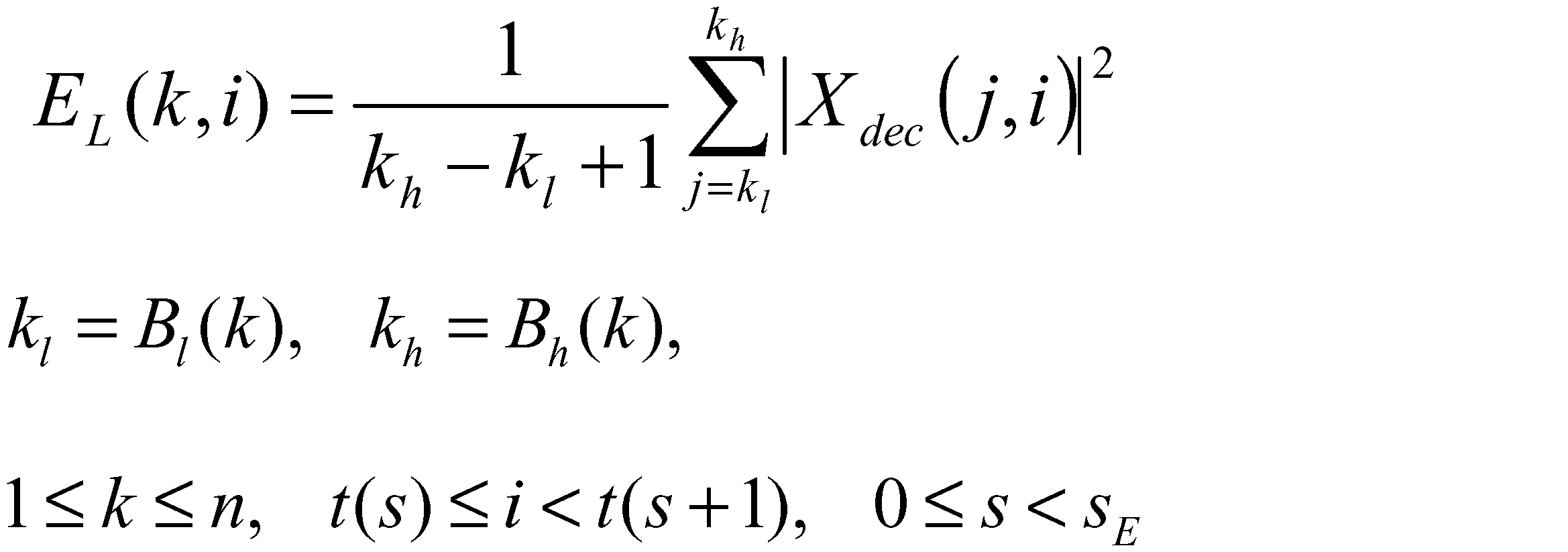
そして、上記EL(k,i)を対象にして、下記式を計算する。


上記式中、sc(j)、0≦j≦dは平滑化係数であり、dは平滑化の次数である。sc(j)は例えば、下記式;
によって設定されるが、本実施形態においてsc(j)の値は上記式には限定されない。

さらには、上記L0(k.i)は例えば下記式で計算してもよい。

ただし、εはゼロ割を回避する緩和係数である。またさらには、上記L0(k.i)は例えば下記式で計算してもよい。


あるいは、下記式;
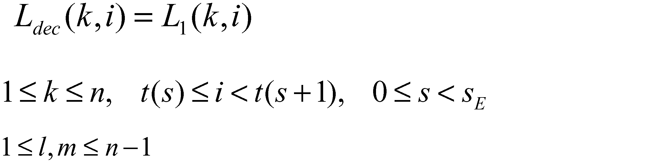
を用いて得られる。
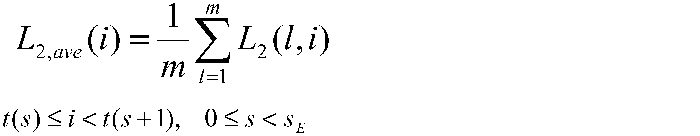
により求める。上記平均を用いて、変位ベクトルを下記式で定義する。
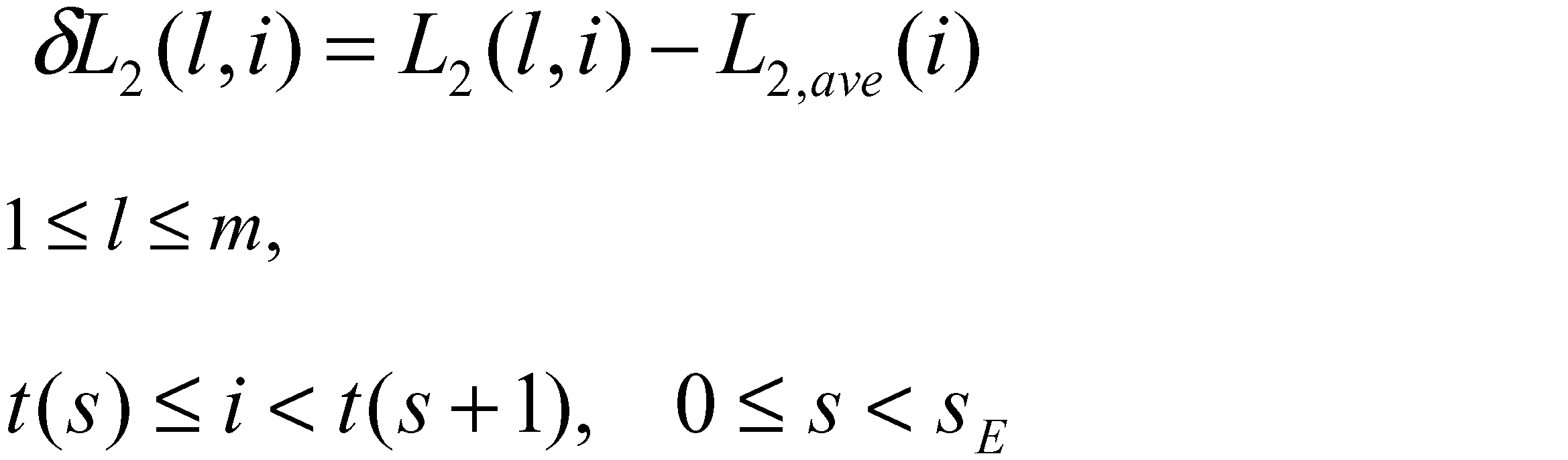
これらの変位ベクトルから、サイズD×Dの分散共分散行列Covを下記式で算出する。

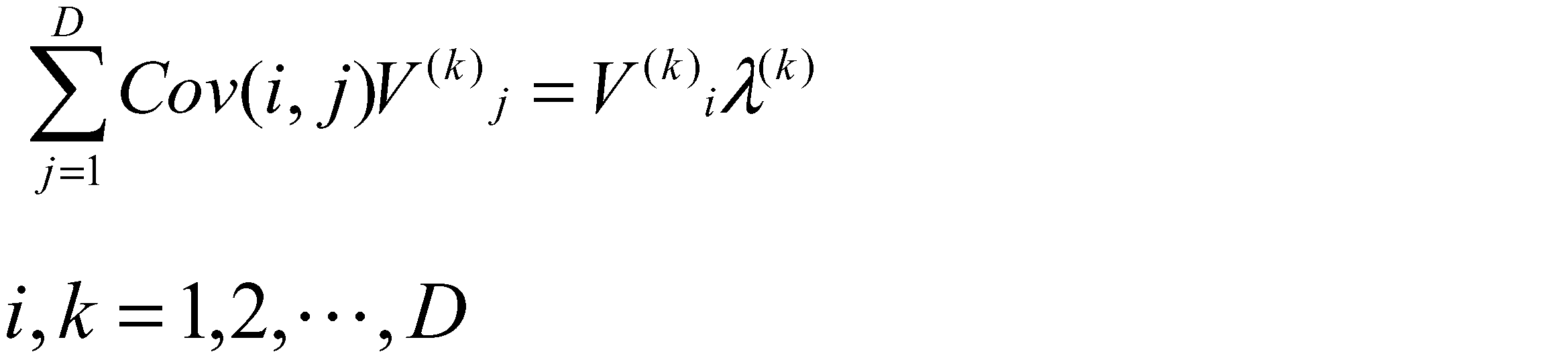
を満たす互いに直交する、行列Covの固有ベクトルV(k)を算出する。ここで、上記V(k) iは固有ベクトルV(k)の成分であり、λ(k)はV(k)に対応する行列Covの固有値である。ここで、上記ベクトルV(k)の各々は、正規化されていてもよい。ただし、正規化の方法は本発明においては限定されない。以降、記述の簡便化のため、λ(1)≧λ(2)≧・・・≧λ(D)とする。
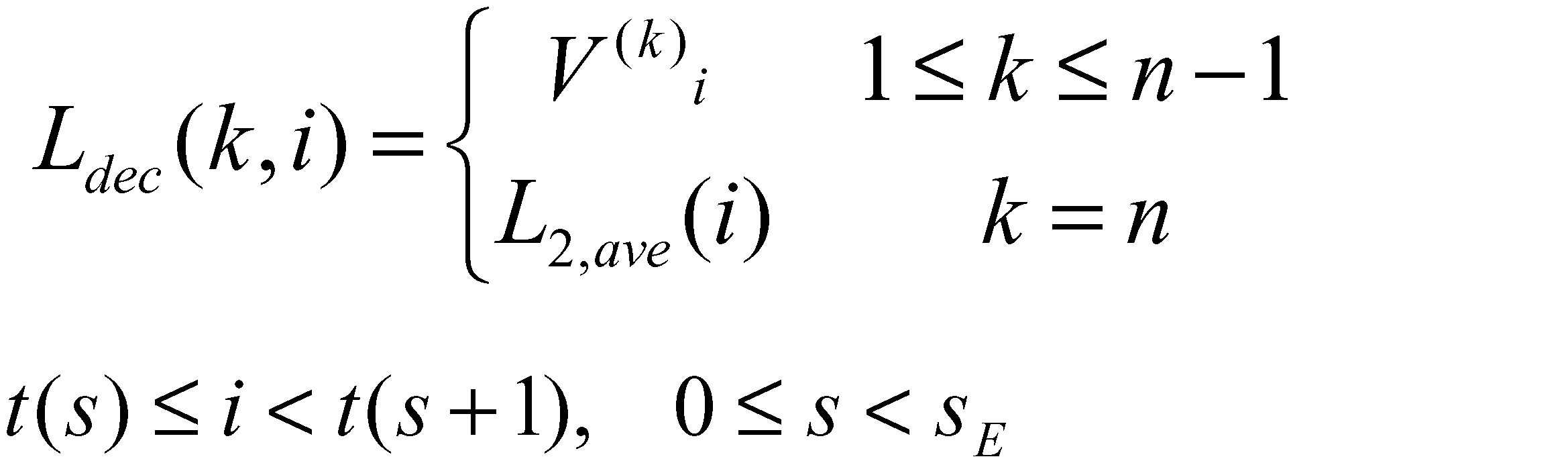
一方、D<m(=n-1)なら、上記固有ベクトルを用いて、下記式により算出する。

ここで、αは定数であり、例えば、α=0としてもよい。また、同じくD<m(=n-1)の場合、下記式により算出してもよい。

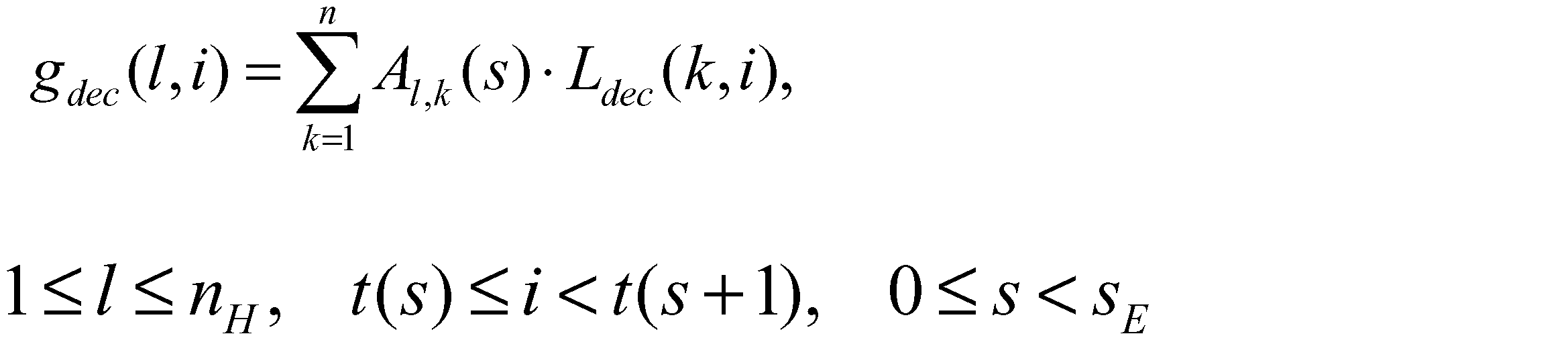
ここで、上記式中に示された値;
は、符号化系列復号/逆量子化部1eから与えられた時間エンベロープ情報である。
なる係数を含むものであってもよく、その場合は、上記gdec(l,i)が、下記式;
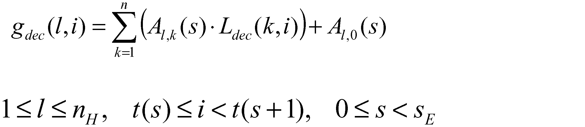
によって与えられてもよい。
で与えられる係数を含むものであってもよく、その場合は、上記gdec(l,i)が、下記式;
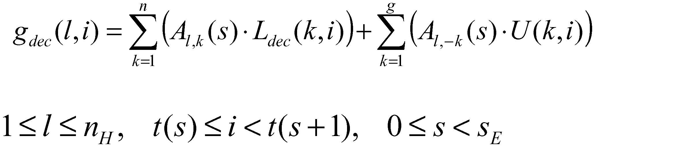
あるいは、下記式;

によって与えられるとしても良い。ここで、U(k,i){1≦k≦g、t(s)≦i<t(s+1)、0≦s<sE}は所定の係数、あるいは、所定の関数である。例えば、上記U(k,i)は、下記式で与えられる関数でもよい。
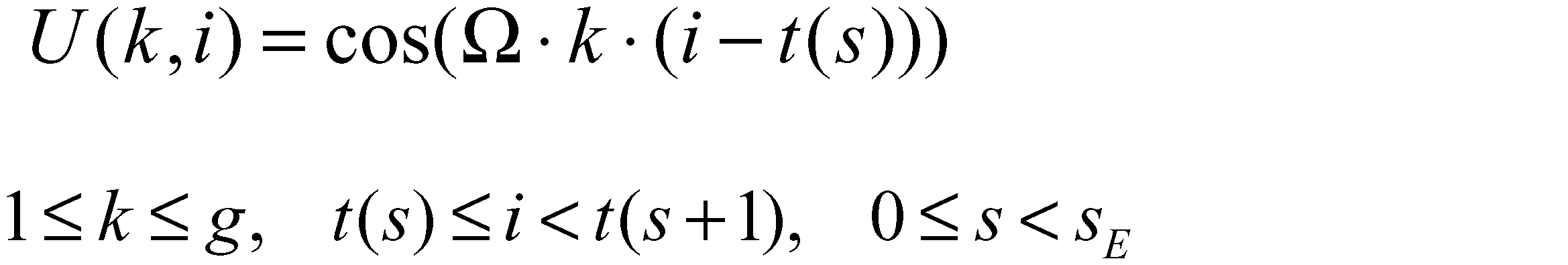
ここで、Ωは所定の係数である。
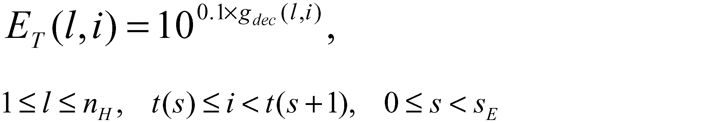
あるいは、下記式;
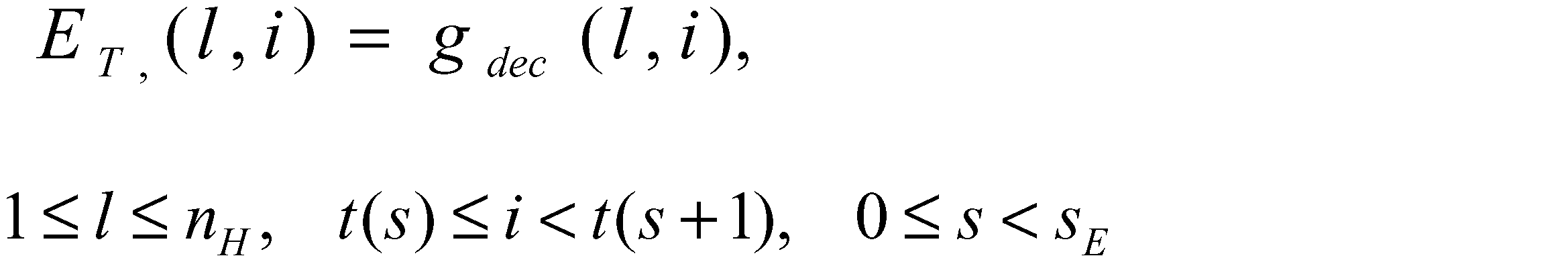
により時間エンベロープを算出する。
Audio Coding”)。
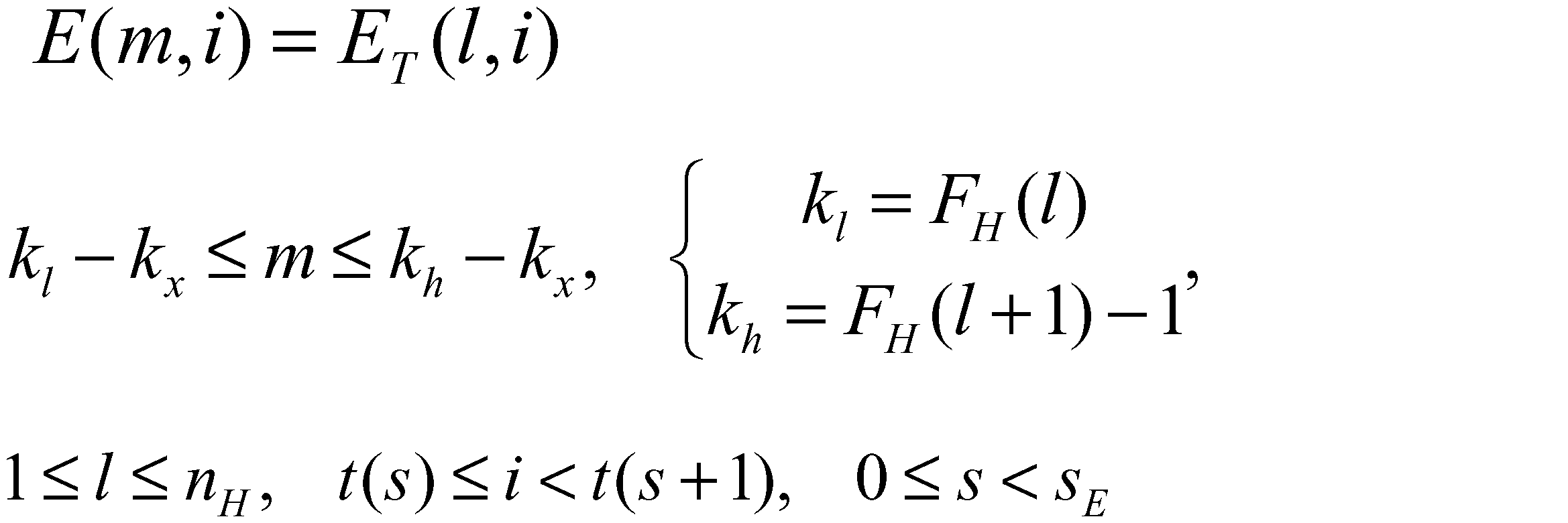
その後、符号化系列復号/逆量子化部1eによって与えられるノイズフロアー・スケールファクターQ(m,i)を下記式で変換する。

ただし、M=F(nH+1)-F(1)である。また、ゲインを下記式で算出する。

ここで、下記式;

により表される量を定義する。
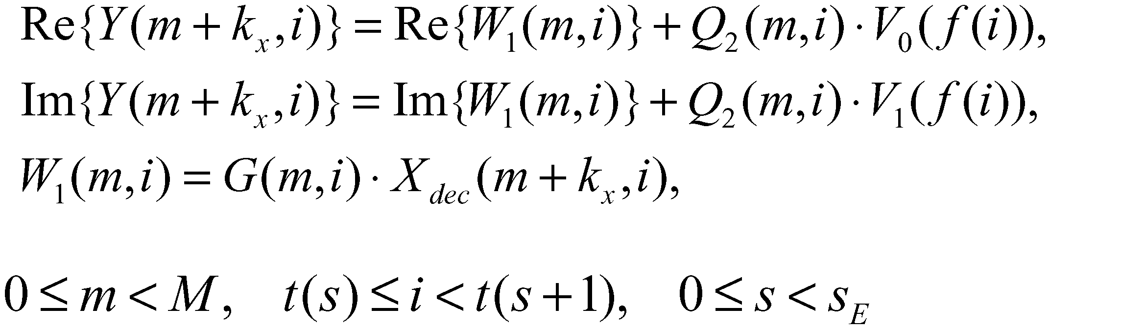
ここで、V0、V1はノイズ成分を規定する配列であり、fは、インデックスiを上記配列上のインデックスに写像する関数である(具体例については、“ISO/IEC 14496-3 4.B.18”を参照。)。
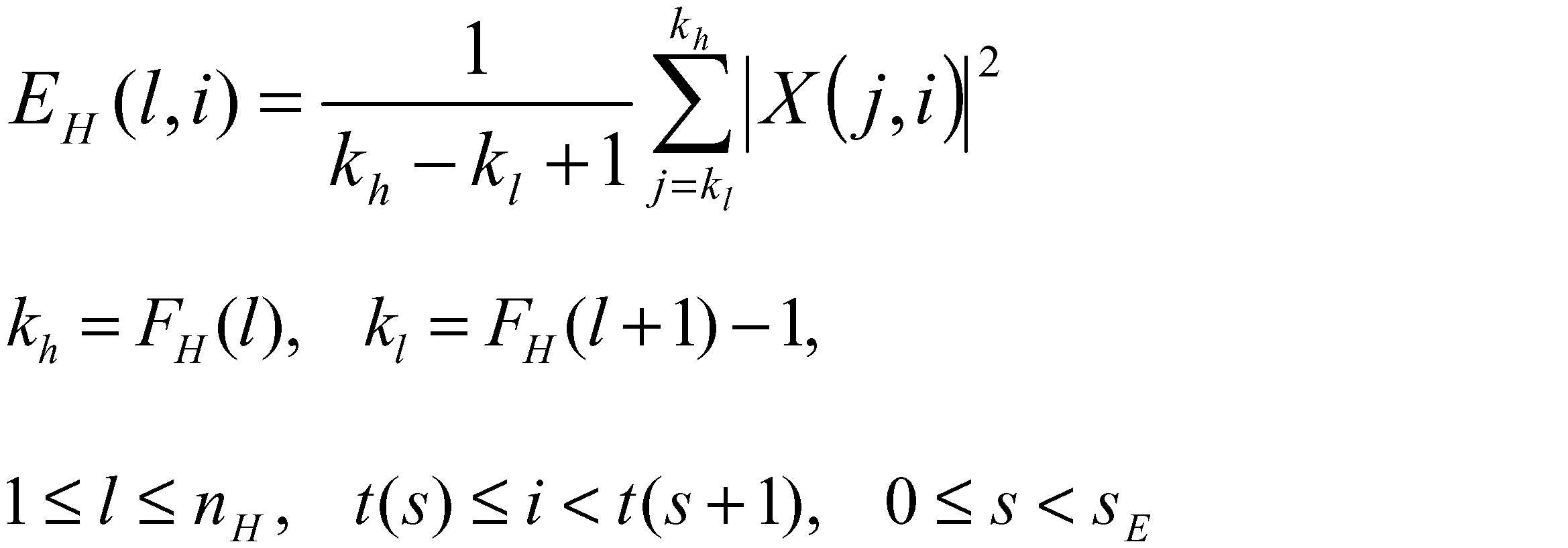
次に、上記高周波数帯域の第l(1≦l≦nH)番目の周波数帯域の参照時間エンベロープを、H(l、i){t(s)≦i<t(s+1)}と表すことにすると、参照時間エンベロープH(l、i)は、下記式;

又は、下記式;
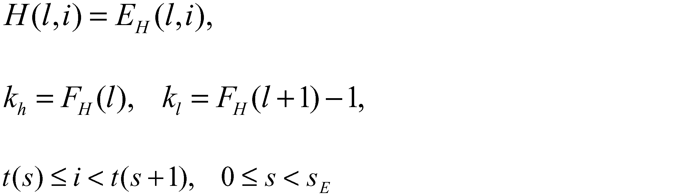
によって算出される。
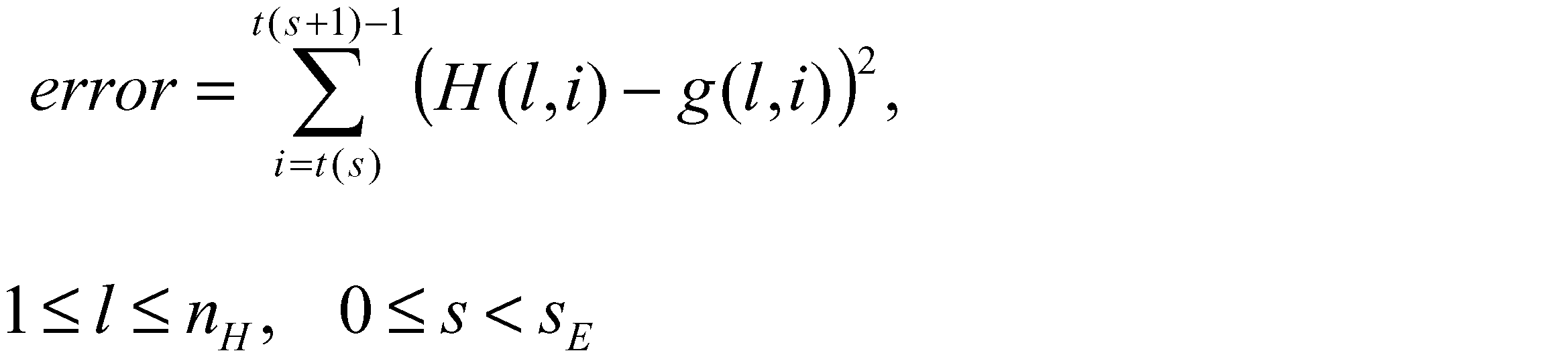
によって計算される。また、この誤差は、下記式を利用して重みつき誤差として計算されてもよい。

さらには、誤差は下記式によって計算されてもよい。
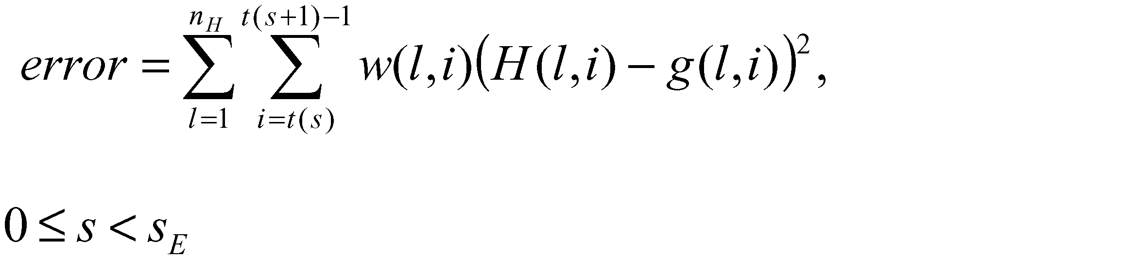
ここで、重みw(l,i)は時間インデックスiにより変化する重みとしても、あるいは、周波数インデックスlにより変化する重みとしても定義してよく、さらに時間インデックスi及び周波数インデックスlにより変化する重みとして定義してもよい。なお、本実施形態においては、上記誤差の形態、および、上記例にある重みの形態には限定されない。

とする)(ステップS36)に、帯域合成フィルタバンク部1jに送られる。一方、時間エンベロープ算出制御部1kは、低周波数帯域信号の電力が所定の閾値よりも大きい場合には、低周波数帯域時間エンベロープ算出部1f1~1fnには低周波数帯域時間エンベロープ算出制御信号を、時間エンベロープ算出部1gには時間エンベロープ算出制御信号を出力して、低周波数帯域時間エンベロープ算出部1f1~1fnおよび時間エンベロープ算出部1gは時間エンベロープの算出処理を実施するように制御する。この場合、時間エンベロープ調整部1iにて上記時間エンベロープに基づいて時間エンベロープが調整された高周波数帯域信号は帯域合成フィルタバンク部1jに送られる。
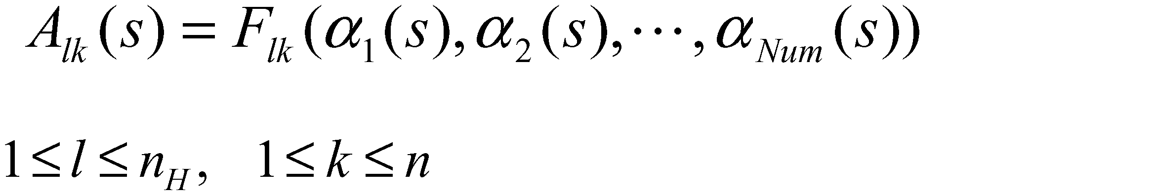
0≦s<sE
ここで、αk(s)、k=1,2,・・・,Num、0≦s<sEは符号化系列復号/逆量子化部1eから与えられる時間エンベロープ情報であり、Flk(x1,x2,・・・,xNum)、1≦l≦nH、1≦k≦nは、Num個の変数を引数とする所定の関数である。その後、上記の方法で取得された係数Al,k(s)を用いて、数式18、数式21、数式23、あるいは、数式24により、時間エンベロープを算出する。
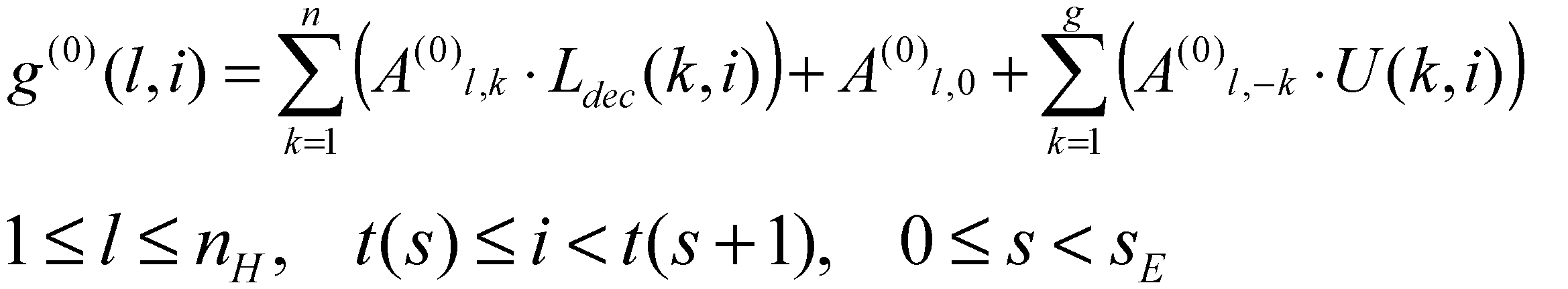
ここで、下記式;
は、所定の係数である。
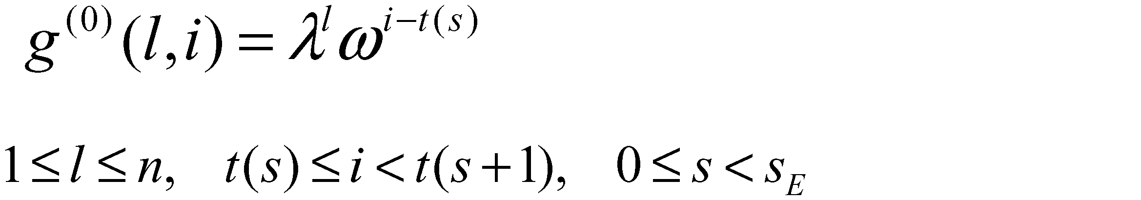
ここで、λ、ωは所定の係数である。

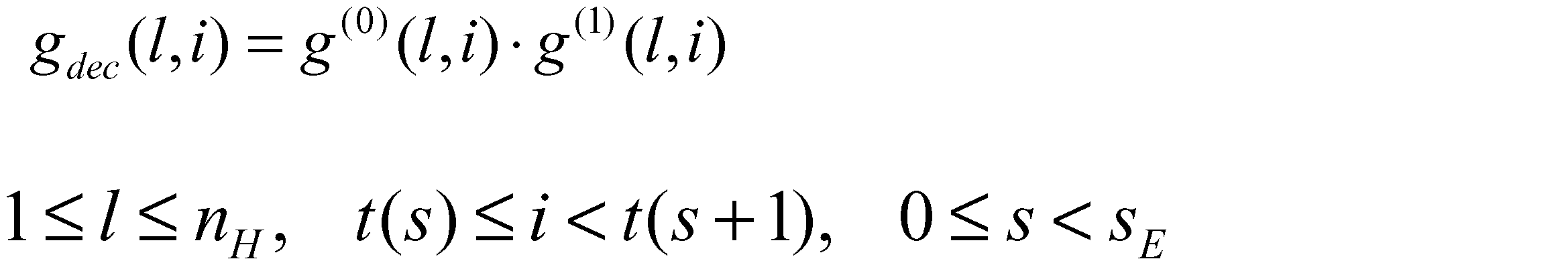

により時間エンベロープが算出されても良い。
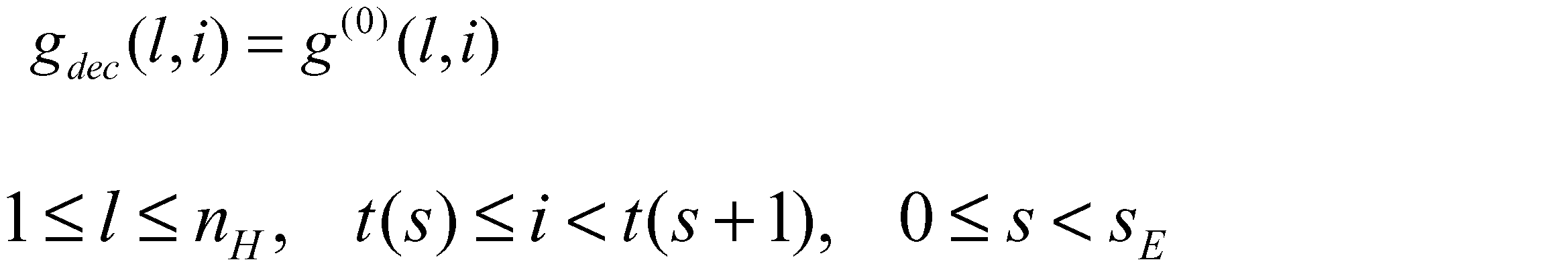
により時間エンベロープが算出されてもよい。
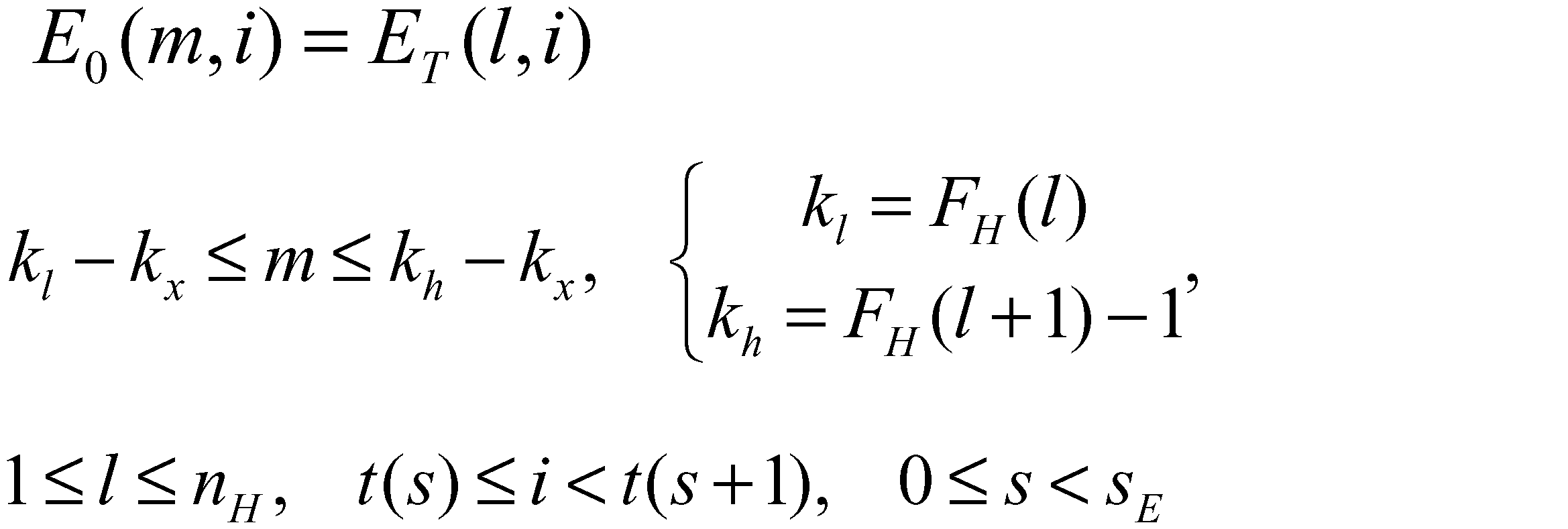

ここで、上記sfdec(k,s)(ただし、1≦k≦mH、0≦s<sE)は、副周波数帯B(F) kに対応するスケールファクタである。

本実施形態においては、上記EF,dec(k,s)の形態は上記例に限定されない。
ここで、C=0としてもよいが、本実施形態においては、Cの値は規定されない。そして、周波数エンベロープ重畳部1qは、整数1が集合Ncに含まれなければ、周波数エンベロープ情報から、スケールファクタsfdec(1、s)、0≦s<sを取得する。
(ステップk)
整数kが集合Ncに含まれなければ、周波数エンベロープ情報から、スケールファクタの差分dsfdec(k、s)、0≦s<sを取得し、下記式;
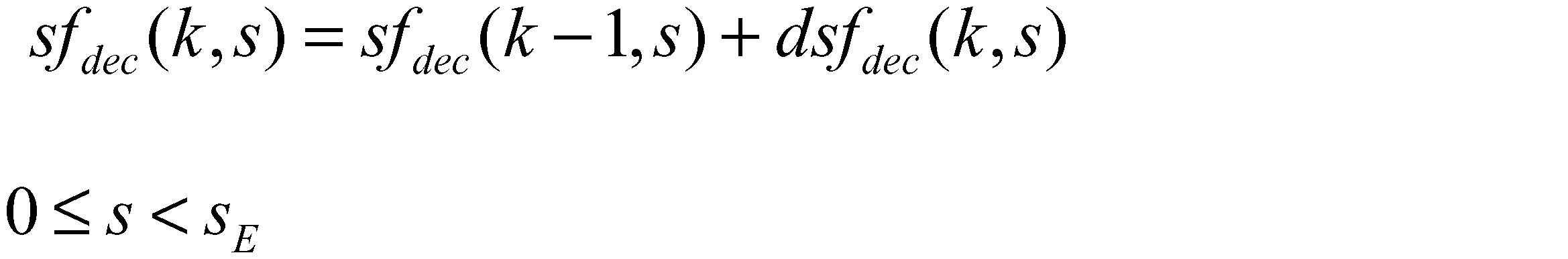
によりスケールファクタを算出し、整数kに1を加算して次の(ステップk)の処理に進む。一方、整数kが集合Ncに含まれる場合は、そのまま、整数kに1を加算して次の(ステップk)の処理に進む。
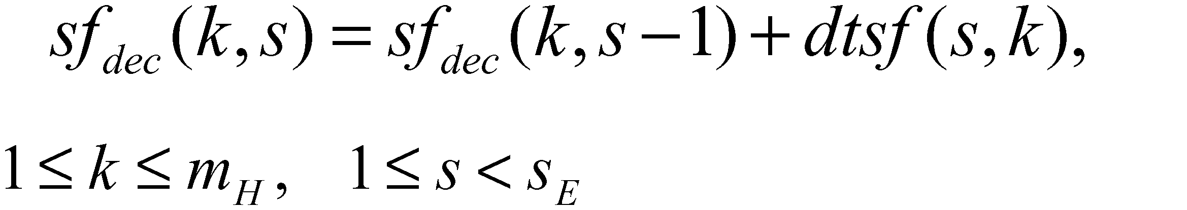
ただし、この場合、初期値に対応する、sfdec(k、0)、1≦k≦mHは上記の方法等、別の手段を用いて取得する。
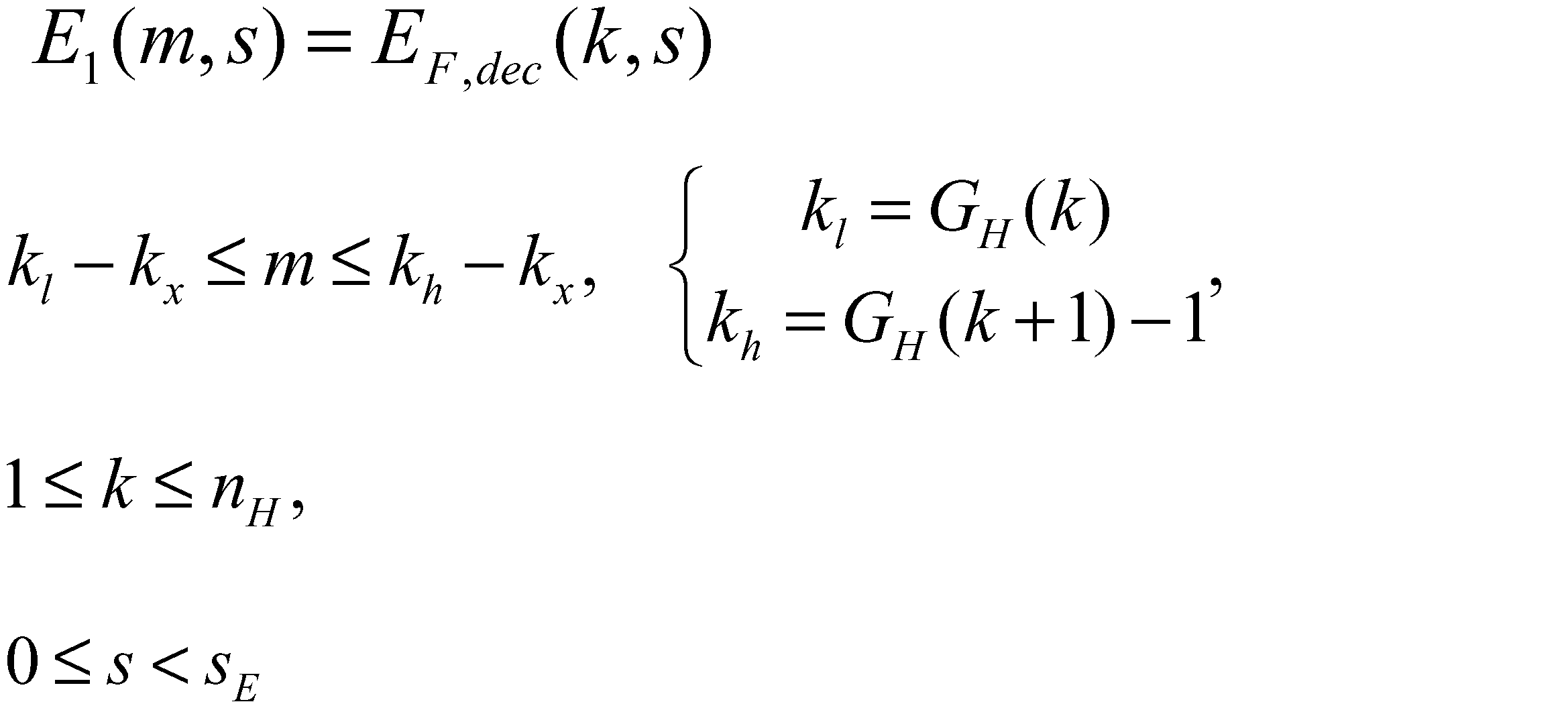
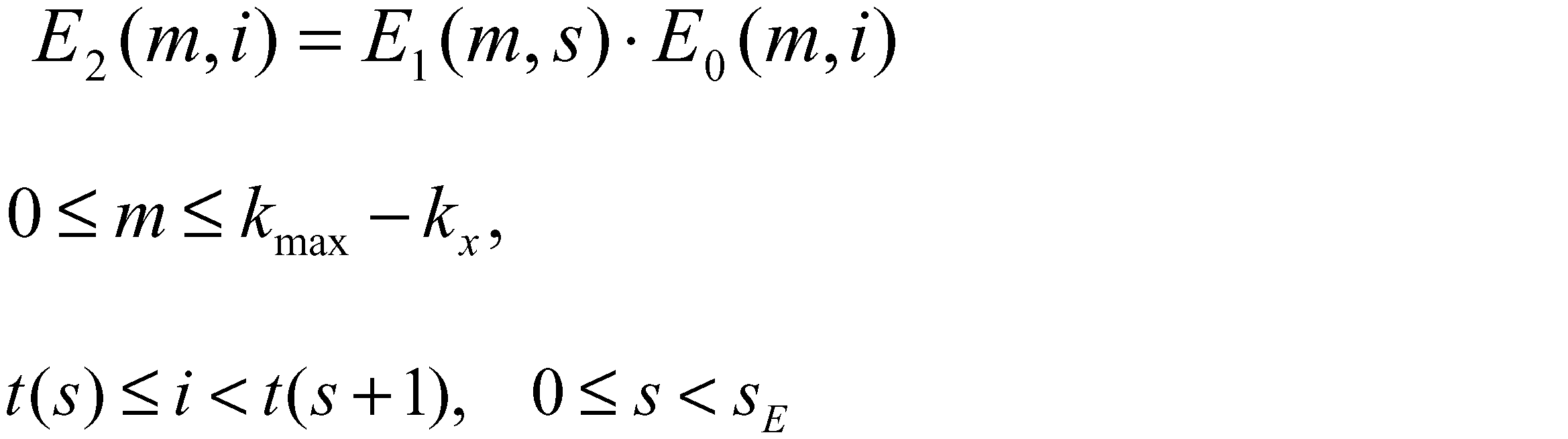

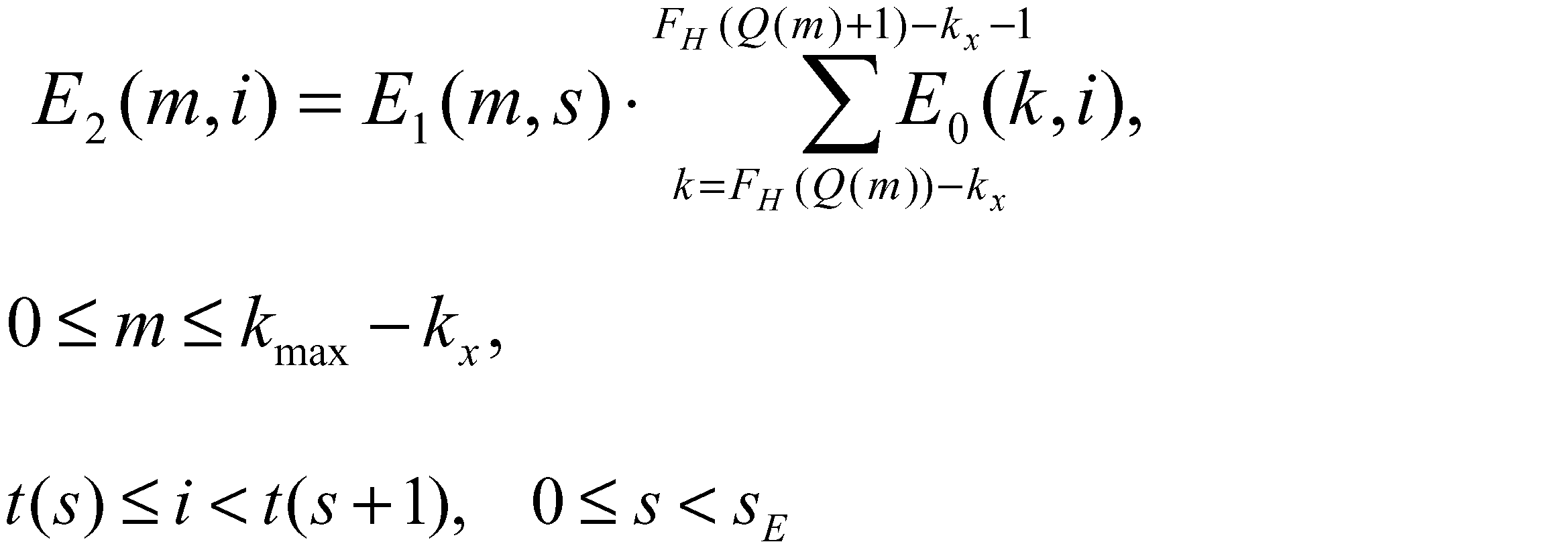
ここで、Q(m)、0≦m<kmax-kxは、下記式の条件を満たす整数である。
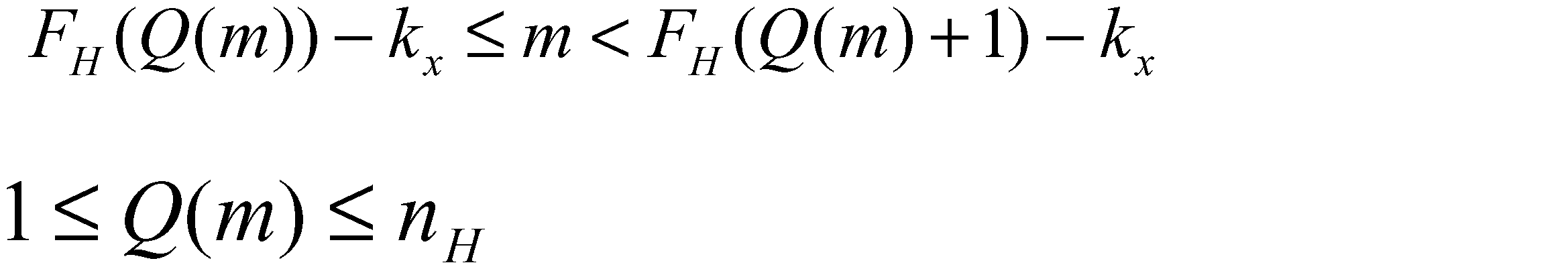
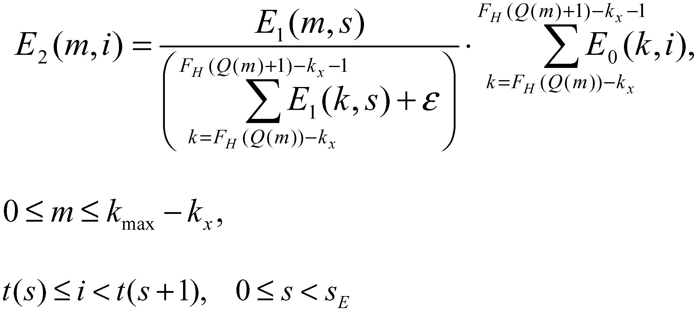
ただし、本発明においては、上記E2(m,i)の形態は、上記例に限定されない。
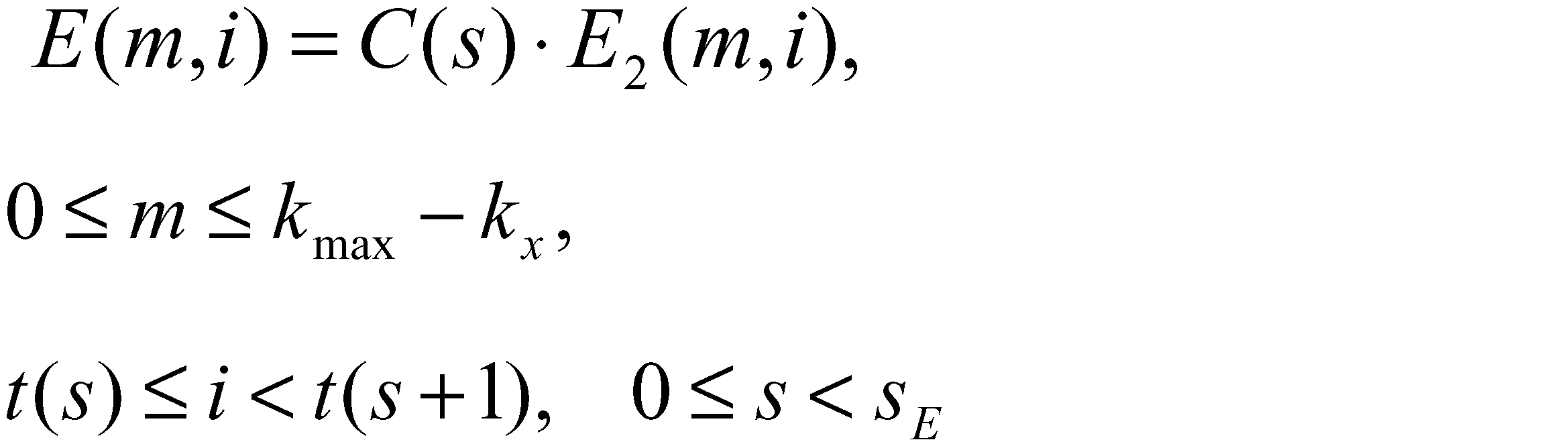
ここで、係数C(s)は、下記式で与えられる。


としてもよい。

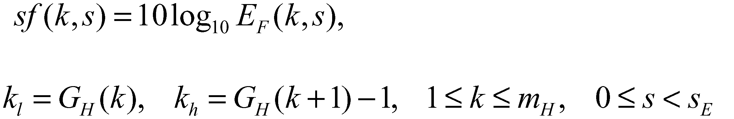
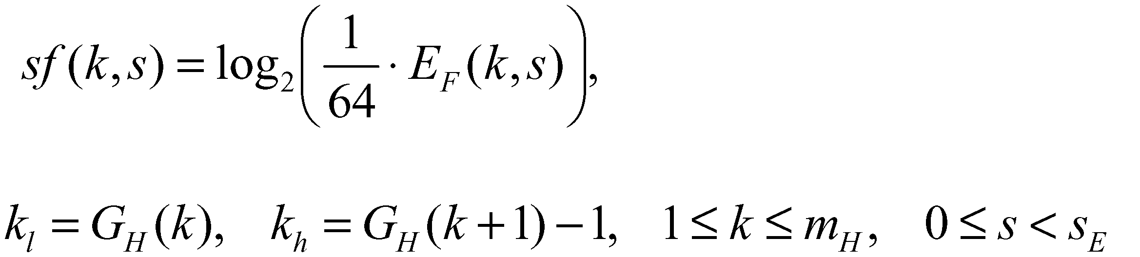
また、音声復号装置101側に対応して、下記式;
によって設定しても良い。

により定義し、上記dsf(k、s)とsf(1、s)(0≦s<sE)を周波数エンベロープ情報としてもよい。
14496-3 4.B.18”に記載の方法に従い、上記式のsf(k,s)を用いて、下記式;
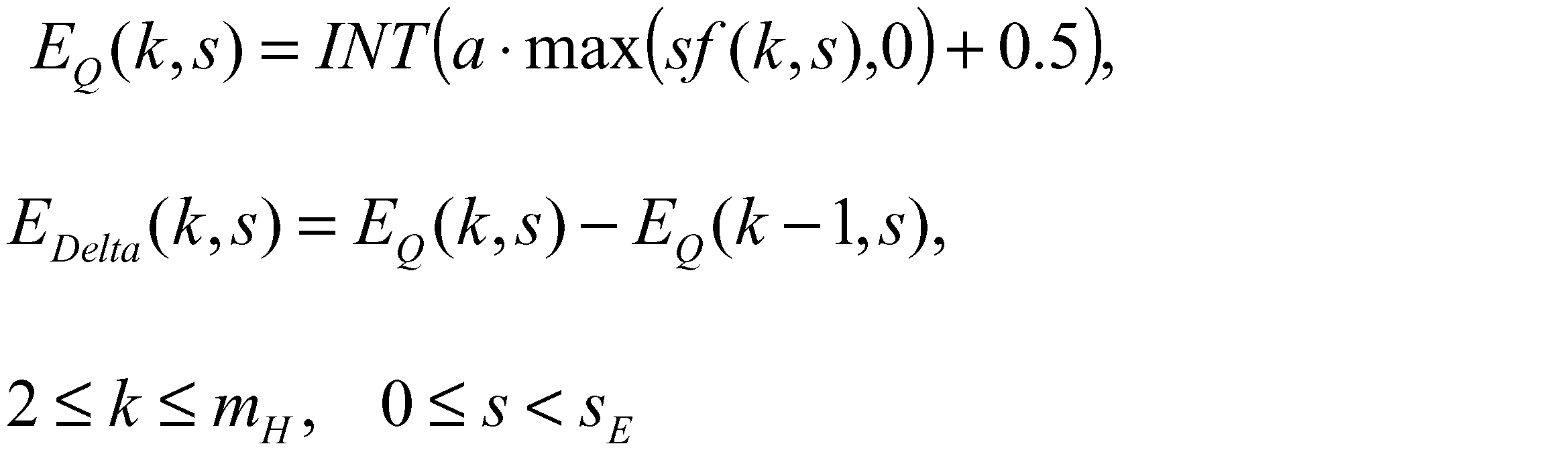
によってEDelta(k,s)を算出し、EDelta(k,s)をハフマン符号化してもよい。
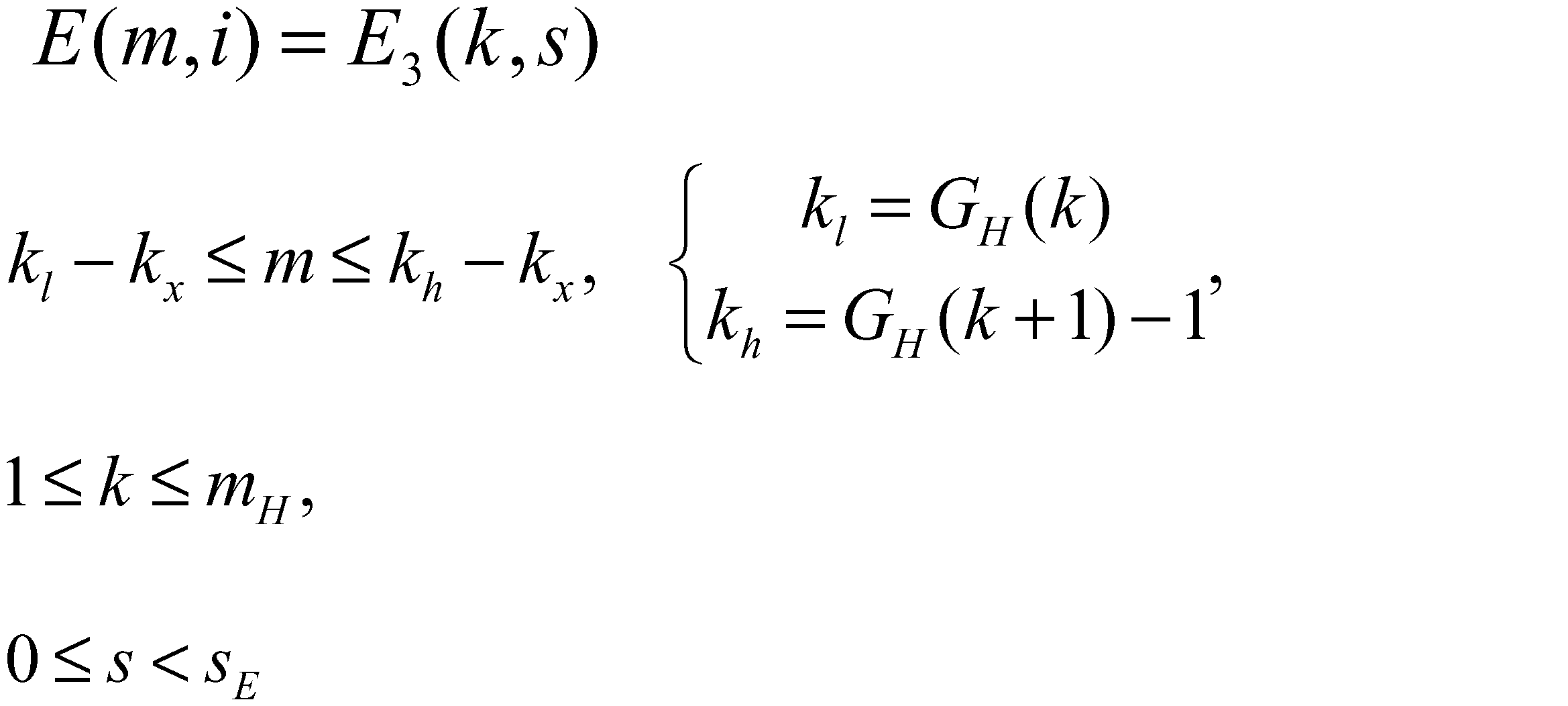
本変形例では、第1の実施形態にかかる音声復号装置1の時間エンベロープ算出部1gでは、算出した時間エンベロープに所定の関数に基づく処理を施す。例えば、時間エンベロープ算出部1gは、時間エンベロープを時間的に正規化する処理をし、下記式にて時間エンベロープET’(l, i)を算出する。
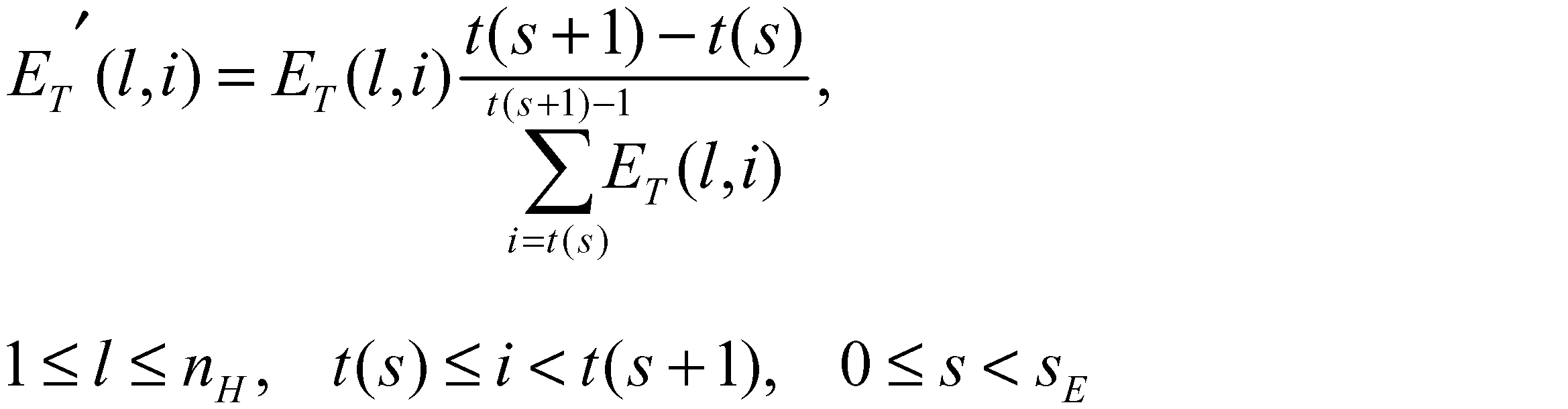
本変形例では、時間エンベロープET’(l,
i)を算出した後では、それ以降の処理において量ET(l,i)を量ET’(l,i)に置き換えて処理することができる。
本変形例では、第1の実施形態にかかる音声復号装置1の第1~第n低周波数帯域時間エンベロープ算出部1f1~1fnにおいて、量L0(k, i)を時間方向に平滑化して時間エンベロープL1(k, i)を取得する際には、フレームs-1からフレームsに移行する際にL0(k,i)(t(s)-d≦i<t(s))を保持しておく。本変形例によれば、フレームs-1との境界に近いフレームsの量L0(k, i)(より具体的には、L0(k,i) (t(s)≦i<t(s)+d))に対しても平滑化ができる。
本変形例では、第1の実施形態の音声符号化装置2にかかる時間エンベロープ情報算出部2fにおける時間エンベロープ情報の算出は、参照時間エンベロープH(l,i)と上記g(l,i)の相関に基づいて実施される。例えば、時間エンベロープ情報算出部2fは、以下のように時間エンベロープ情報を算出する。
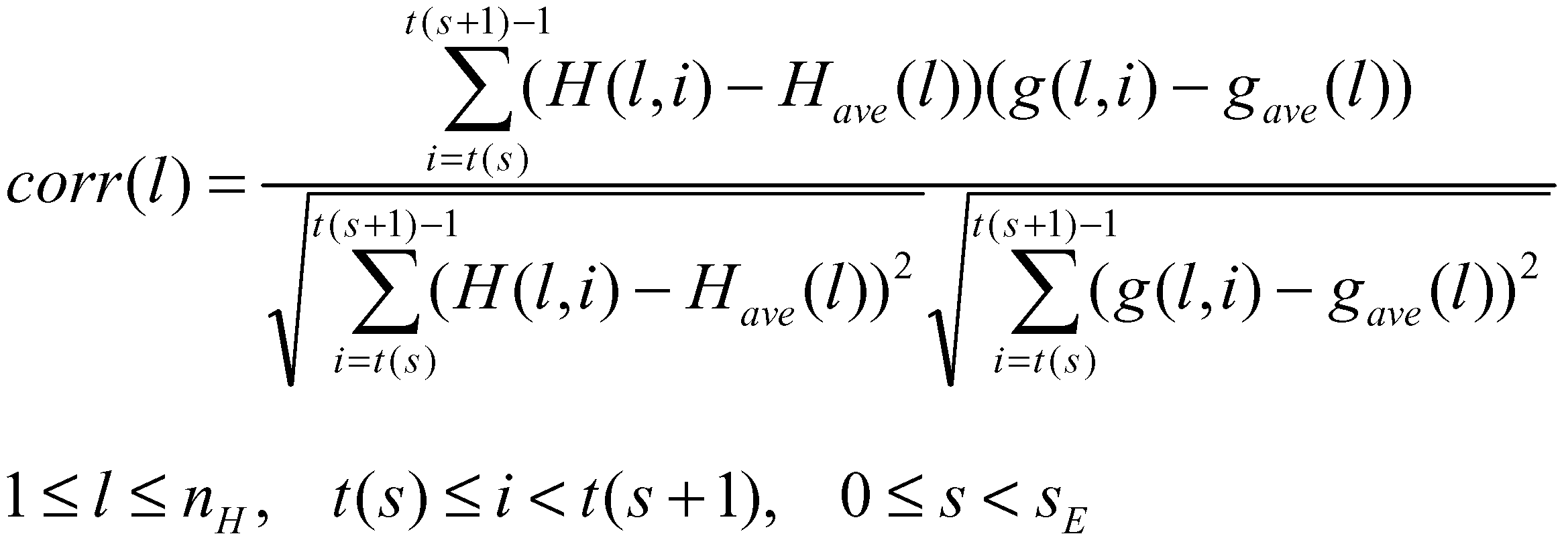
上記相関係数corr(l)を所定の閾値と比較し、その比較結果に基づいて時間エンベロープ情報を算出する。さらには、corr2(l)に相当する値を求めて所定の閾値と比較し、その比較結果に基づいて時間エンベロープ情報を算出することでも実現できる。
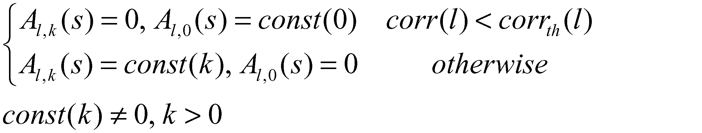
本変形例では、第2の実施形態の音声復号装置101にかかる周波数エンベロープ重畳部1qにおいて、周波数エンベロープEF,dec(k,s)に所定の関数に基づく処理を施す。例えば、周波数エンベロープ重畳部1qは、下記式にて与えられる周波数エンベロープEF,dec(k,s)を平滑化する関数に基づく処理を施す。

ただし、
であり、sch(j)、dhは、それぞれ所定の平滑化係数、平滑化次数である。この際には、以降の処理において、EF,dec,Filt(k,i)をEF,dec(k,s)として置き換えて処理を進めればよい。
第2の実施形態の音声復号装置101にかかる周波数エンベロープ重畳部1qにおいては、量E(m, i)はC(s)によりE2(m, i)を補正した値になっている(数式60)。また、数式61によると、フレームsの帯域kx≦m≦kmaxにおける時間/周波数エンベロープ調整後の高周波数帯域信号のエネルギーが、フレームsの帯域kx≦m≦kmaxにおける時間エンベロープE0(m,i)の総和になるように補正されている。一方、数式62によると、フレームsの帯域kx≦m≦kmaxにおける時間/周波数エンベロープ調整後の高周波数帯域信号のエネルギーは、フレームsの帯域kx≦m≦kmaxにおける周波数エンベロープE1(m,i)の総和になるように補正されている。本変形例では、C(s)は、フレームsの帯域kx≦m≦kmaxにおける時間/周波数エンベロープ調整後の高周波数帯域信号のエネルギーが時間/周波数エンベロープ調整後も保持されるように、下記式によって与えられる。
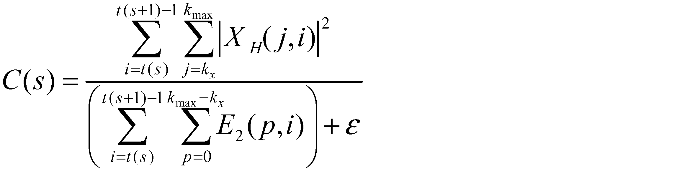
adjustment)と同様に、符号化系列復号/逆量子化部1eによって与えられるフレームsにおけるノイズフロアー・スケールファクターQ(m,s)は下記式で変換する。
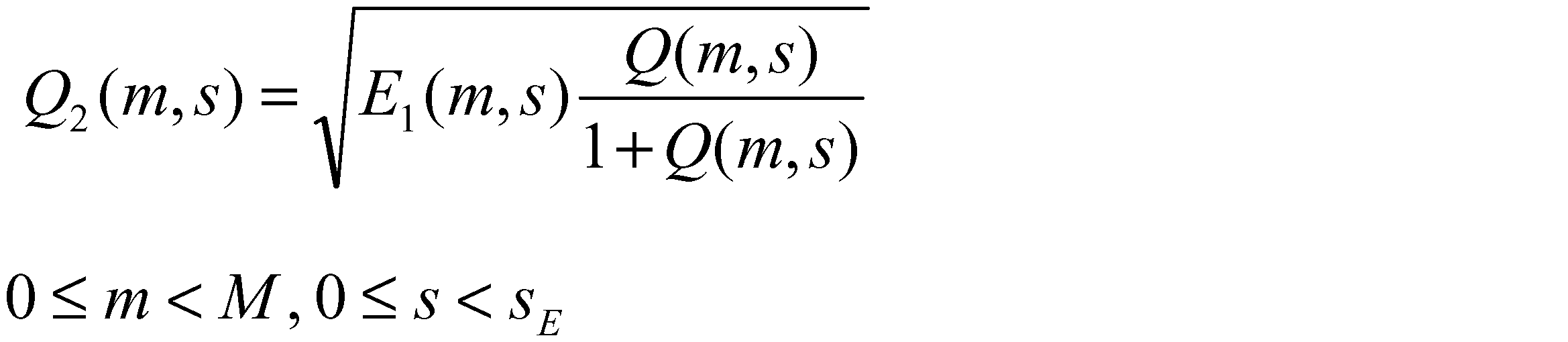
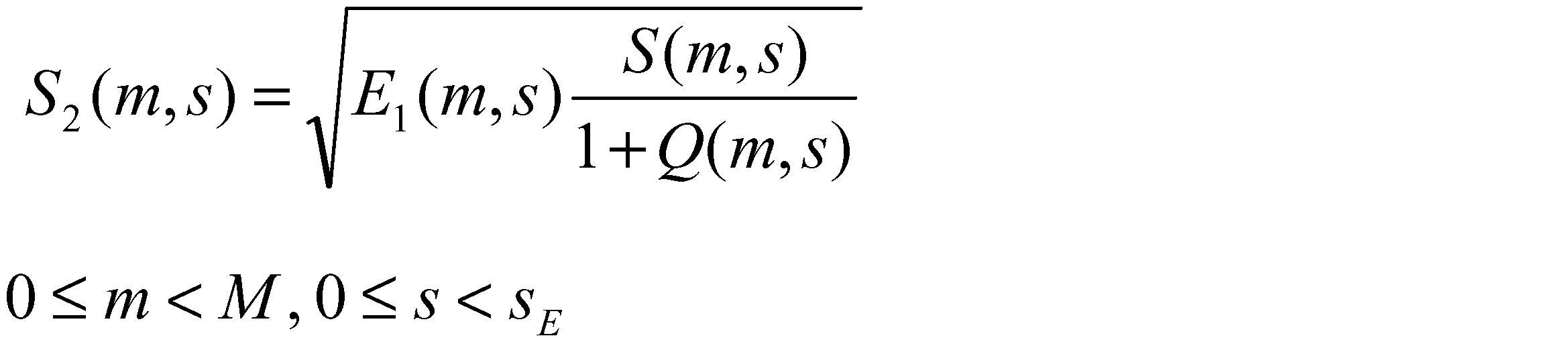


また、下記式によっても定義できる。

また、S’(m,s)は、フレームsにおいて、インデックスmが表す周波数を含む副周波数帯B(F) k(GH(k)≦m<GH(k+1))内に付加されるシヌソイドがあるか否かを表す関数であり、付加されるシヌソイドがある場合は“1”、それ以外の場合は“0”となる。
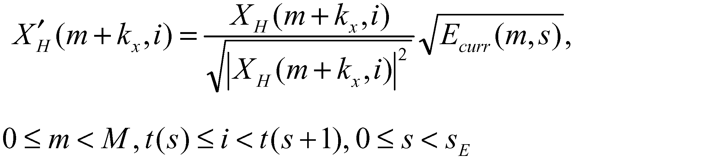

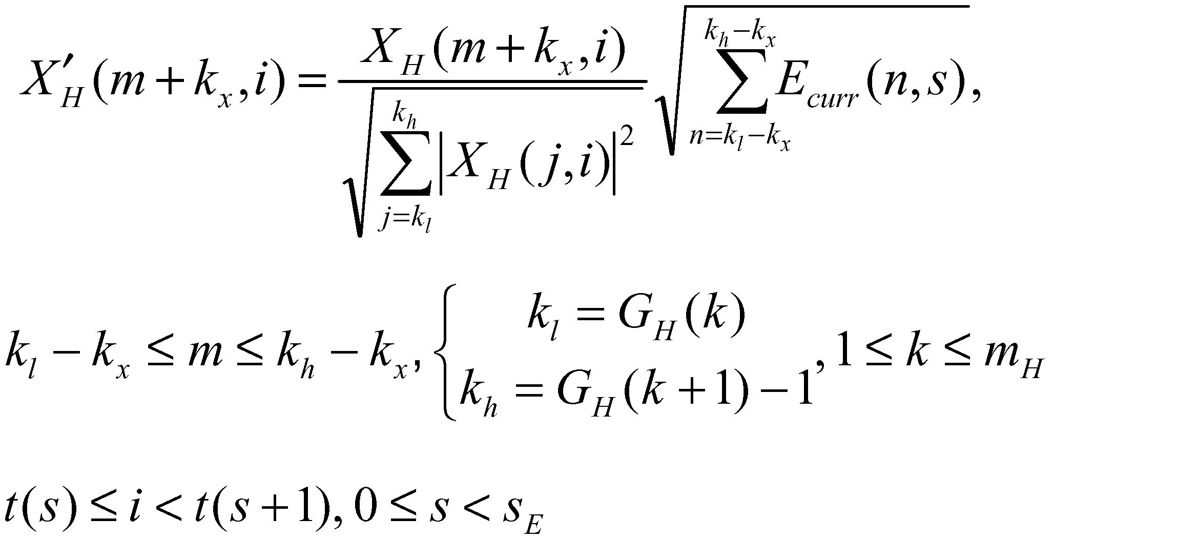
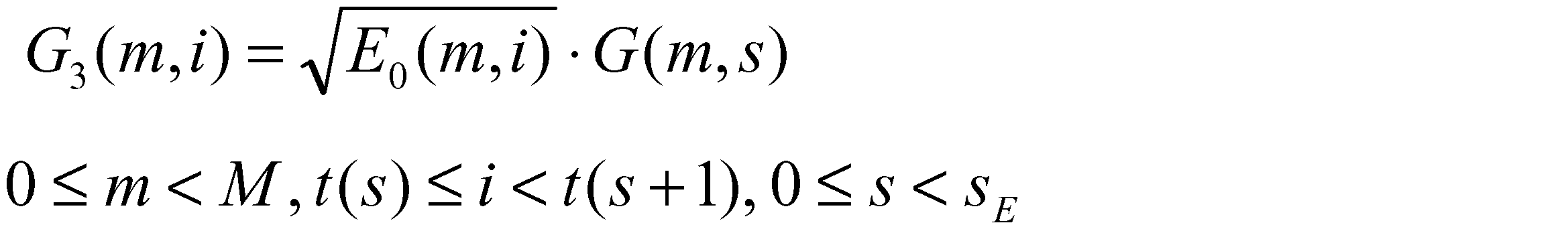
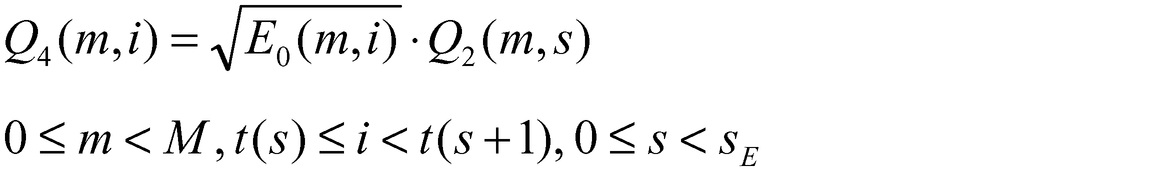
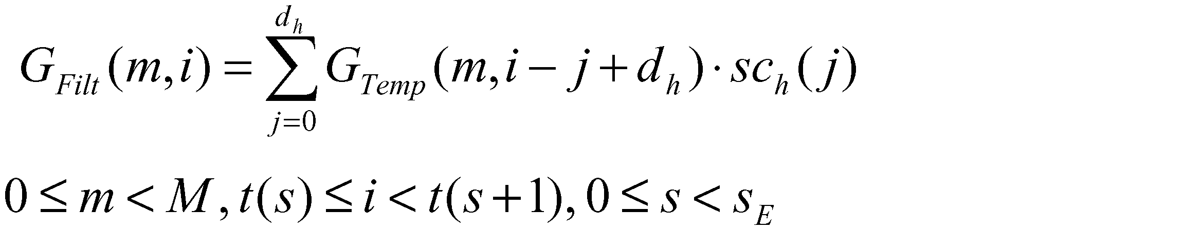

ただし、sch(j)、dhは、それぞれ所定の平滑化係数、平滑化次数である。また、GTemp(m,i)、QTemp(m,i)は下記式にて与えられる。
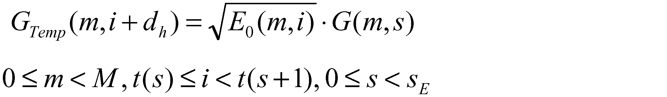


ただし、wold(m,i)、wcurr(m,i)は、それぞれ所定の重み係数である。また、GTemp(m,i)、QTemp(m,i)は下記式にて与えられる。


上記所定の関数に基づく処理を施した場合は、以降の処理において、G3(m,s),Q4(m,s)に代わって、GFilt(m,s),QFilt(m,s)を用いる。


ここで、V0、V1はノイズ成分を規定する配列であり、fは、インデックスiを上記配列上のインデックスに写像する関数であり、φRe,sin、φIm,sinはシヌソイド成分の位相を規定する配列であり、fsinは、インデックスiを上記配列上のインデックスに写像する関数である(具体例については、“ISO/IEC 14496-3 4.6.18”を参照)。
AAC”のSBRにおけるHFアジャストメントのゲインブースタを本発明の第2の実施形態の音声復号装置101にかかる周波数エンベロープ重畳部1qにて適用すると、副周波数帯域B(F) k(GH(k)≦j<GH(k+1))ごとにフレームs単位で、ゲイン制限によるエネルギーの損失の補償をすることになる。一方で下記式によれば、副周波数帯域B(F) k(GH(k)≦j<GH(k+1))ごとに高周波数帯域信号XH(j,i)については時間インデックスi単位で、ゲイン制限によるエネルギーの損失の補償をすることになる。
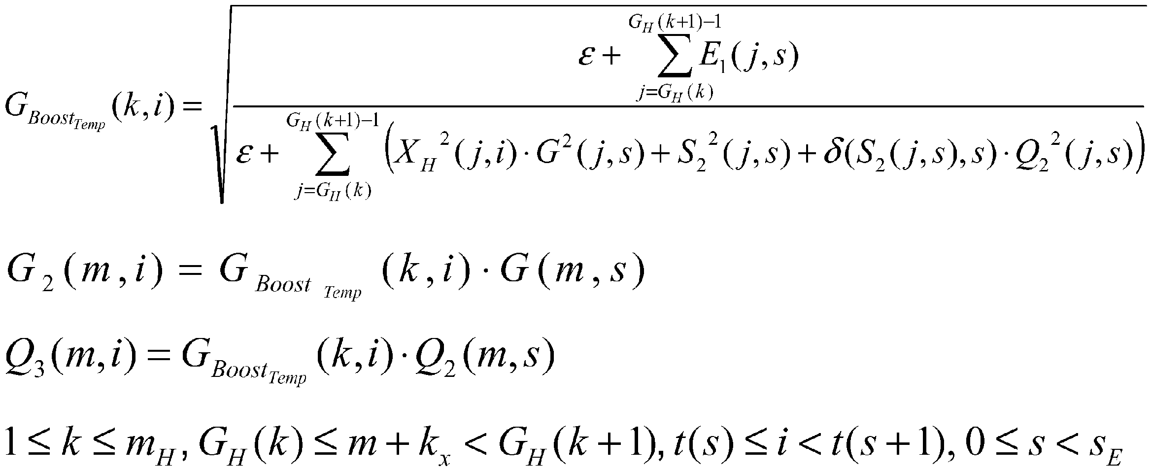

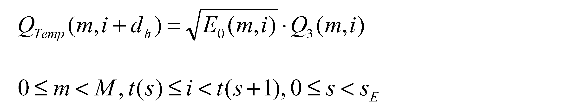
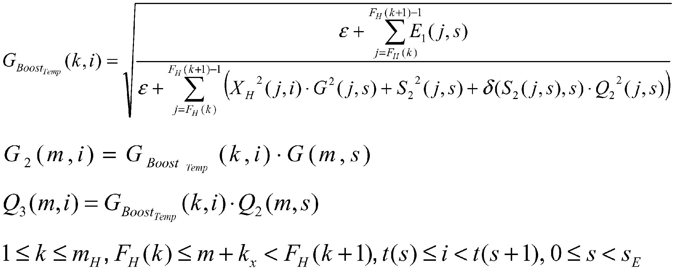

Adjustment)と類似の手段により行われる。そのため、MPEG4 AAC”のSBRにおけるHFアジャストメント(HF adjustment)と同様に、ゲイン,ノイズフロアー・スケールファクター,シヌソイドレベルに対し、不必要なノイズの付加を避けるためのゲイン制限(ゲインリミッタ Gain limiter)、ゲイン制限によるエネルギーの損失の補償(ゲインブースタ Gain booster)の関数に基づく処理をする場合,当該処理を時間インデックスi(t(s)≦i<t(s+1))に対して実施する。一方、本変形例によると、ゲイン,ノイズフロアー・スケールファクター,シヌソイドレベルに対し、不必要なノイズの付加を避けるためのゲイン制限(ゲインリミッタ Gain limiter)、ゲイン制限によるエネルギーの損失の補償(ゲインブースタ Gain booster)の関数に基づく処理をする場合に、当該処理のうち少なくとも1つの処理はフレームsに対して実施すればよい。従って、本変形例では第2の実施形態の音声復号装置101に比べ、上記の処理の演算量を削減することができる。
上記変形例において、第1の実施形態の音声復号装置1の第1、第2、第3の変形例、及び当該変形例の処理を少なくとも一つ以上実行する第1の実施形態の音声復号装置1の第5の変形例を適用した場合には、時間エンベロープ算出部1gが時間エンベロープET(l,i)を算出しない場合が生じる。このような場合は、E0(m,i)が必要な演算処理では、E0(m,i)を1に置き換えて実行する。この方法により、E0(m,i)、E0(m,i)のべき乗、E0(m,i)の平方根を乗じる処理を省略することができ、演算量を削減できる。なお、上記の方法を用いた処理では、時間/周波数エンベロープ調整部1pはE0(m,i)を算出する必要がない。
時間エンベロープ情報算出部2fは、帯域分割フィルタバンク部2cから得られる周波数領域の信号X(j,i)、音声符号化装置2の通信装置を介して受信された外部からの入力信号、および、ダウンサンプリング部2aからの出力として得られるダウンサンプルされた低周波数帯域の時間領域信号、のうちの少なくとも1つ以上の信号の特性に基づき、時間エンベロープ情報を算出する。上記信号の特性としては、例えば信号の、過渡性、トーナリティ、雑音性などがあるが、本変形例において、信号特性は、これらの具体例に限定されない。
時間エンベロープ算出制御情報生成部2jは、帯域分割フィルタバンク部2cから得られる周波数領域の信号X(j,i)、音声符号化装置2の通信装置を介して受信された外部からの入力信号、および、ダウンサンプリング部2aからの出力として得られるダウンサンプルされた低周波数帯域の時間領域信号、のうちの少なくとも1つ以上の信号の信号特性に応じて、音声復号装置1における低周波数帯域時間エンベロープ算出方法に関する時間エンベロープ算出制御情報を生成する。上記信号の特性としては、例えば信号の、過渡性、トーナリティ、雑音性などがあるが、本変形例において、信号特性は、これらの具体例に限定されない。
第1~第4の実施形態の音声符号化装置の量子化/符号化部2gについては、ノイズフロアー・スケールファクターや、シヌソイドを付加するか否かを決めるパラメータも量子化・符号化してもよいことは明白である。
Claims (21)
- 音声信号を符号化した符号化系列を復号する音声復号装置であって、
前記符号化系列を、低周波数帯域符号化系列と高周波数帯域符号化系列とに非多重化する非多重化手段と、
前記非多重化手段によって非多重化された前記低周波数帯域符号化系列を復号して低周波数帯域信号を得る低周波数帯域復号手段と、
前記低周波数帯域復号手段によって得られた前記低周波数帯域信号を、周波数領域に変換する周波数変換手段と、
前記非多重化手段によって非多重化された前記高周波数帯域符号化系列を解析して、符号化された高周波数帯域生成用補助情報および時間エンベロープ情報を取得する高周波数帯域符号化系列解析手段と、
前記高周波数帯域符号化系列解析手段によって取得された前記高周波数帯域生成用補助情報および時間エンベロープ情報を復号および逆量子化する符号化系列復号逆量子化手段と、
前記周波数変換手段によって周波数領域に変換された前記低周波数帯域信号から、前記符号化系列復号逆量子化手段で復号された前記高周波数帯域生成用補助情報を用いて、前記音声信号の周波数領域の高周波数帯域成分を生成する高周波数帯域生成手段と、
前記周波数変換手段によって周波数領域に変換された前記低周波数帯域信号を分析して、複数の低周波数帯域の時間エンベロープを取得する第1~第N(Nは2以上の整数)の低周波数帯域時間エンベロープ算出手段と、
前記符号化系列復号逆量子化手段によって取得された前記時間エンベロープ情報、および前記低周波数帯域時間エンベロープ算出手段により取得された前記複数の低周波数帯域の時間エンベロープを用いて、高周波数帯域の時間エンベロープを算出する時間エンベロープ算出手段と、
前記時間エンベロープ算出手段で取得された前記時間エンベロープを用いて、前記高周波数帯域生成手段で生成された高周波数帯域成分の時間エンベロープを調整する時間エンベロープ調整手段と、
前記時間エンベロープ調整手段により調整された前記高周波数帯域成分と、前記低周波数帯域復号手段によって復号された前記低周波数帯域信号とを加算し、全周波数帯域成分を含む時間領域信号を出力する逆周波数変換手段と、
を備えることを特徴とする音声復号装置。 - 音声信号を符号化した符号化系列を復号する音声復号装置であって、
前記符号化系列を、低周波数帯域符号化系列と高周波数帯域符号化系列とに非多重化する非多重化手段と、
前記非多重化手段によって非多重化された前記低周波数帯域符号化系列を復号して低周波数帯域信号を得る低周波数帯域復号手段と、
前記低周波数帯域復号手段によって得られた前記低周波数帯域信号を、周波数領域に変換する周波数変換手段と、
前記非多重化手段によって非多重化された前記高周波数帯域符号化系列を解析して、符号化された高周波数帯域生成用補助情報、周波数エンベロープ情報、および時間エンベロープ情報を取得する高周波数帯域符号化系列解析手段と、
前記高周波数帯域符号化系列解析手段によって取得された前記高周波数帯域生成用補助情報、周波数エンベロープ情報、および時間エンベロープ情報を復号および逆量子化する符号化系列復号逆量子化手段と、
前記周波数変換手段によって周波数領域に変換された前記低周波数帯域信号から、前記符号化系列復号逆量子化手段で復号された前記高周波数帯域生成用補助情報を用いて、前記音声信号の周波数領域の高周波数帯域成分を生成する高周波数帯域生成手段と、
前記周波数変換手段によって周波数領域に変換された前記低周波数帯域信号を分析して、複数の低周波数帯域の時間エンベロープを取得する第1~第N(Nは2以上の整数)の低周波数帯域時間エンベロープ算出手段と、
前記符号化系列復号逆量子化手段によって取得された前記時間エンベロープ情報、および前記低周波数帯域時間エンベロープ算出手段により取得された前記複数の低周波数帯域の時間エンベロープを用いて、高周波数帯域の時間エンベロープを算出する時間エンベロープ算出手段と、
前記符号化系列復号逆量子化手段によって取得された前記周波数エンベロープ情報を、前記高周波数帯域の時間エンベロープに重畳して時間周波数エンベロープを取得する周波数エンベロープ重畳手段と、
前記時間エンベロープ算出手段で取得された前記時間エンベロープ、および前記周波数周波数エンベロープ重畳手段で取得された時間周波数エンベロープを用いて、前記高周波数帯域生成手段で生成された高周波数帯域成分の時間エンベロープと周波数エンベロープを調整する、時間周波数エンベロープ調整手段と、
前記時間周波数エンベロープ調整手段により調整された前記高周波数帯域成分と、前記低周波数帯域復号手段によって復号された前記低周波数帯域信号とを加算し、全周波数帯域成分を含む時間領域信号を出力する逆周波数変換手段と、
を備えることを特徴とする音声復号装置。 - 音声信号を符号化した符号化系列を復号する音声復号装置であって、
前記符号化系列を、低周波数帯域符号化系列と高周波数帯域符号化系列とに非多重化する非多重化手段と、
前記非多重化手段によって非多重化された前記低周波数帯域符号化系列を復号して低周波数帯域信号を得る低周波数帯域復号手段と、
前記低周波数帯域復号手段によって得られた前記低周波数帯域信号を、周波数領域に変換する周波数変換手段と、
前記非多重化手段によって非多重化された前記高周波数帯域符号化系列を解析して、符号化された高周波数帯域生成用補助情報、周波数エンベロープ情報、および時間エンベロープ情報を取得する高周波数帯域符号化系列解析手段と、
前記高周波数帯域符号化系列解析手段によって取得された前記高周波数帯域生成用補助情報、周波数エンベロープ情報、および時間エンベロープ情報を復号および逆量子化する符号化系列復号逆量子化手段と、
前記周波数変換手段によって周波数領域に変換された前記低周波数帯域信号から、前記符号化系列復号逆量子化手段で復号された前記高周波数帯域生成用補助情報を用いて、前記音声信号の周波数領域の高周波数帯域成分を生成する高周波数帯域生成手段と、
前記周波数変換手段によって周波数領域に変換された前記低周波数帯域信号を分析して、複数の低周波数帯域の時間エンベロープを取得する第1~第N(Nは2以上の整数)の低周波数帯域時間エンベロープ算出手段と、
前記符号化系列復号逆量子化手段によって取得された前記時間エンベロープ情報、および前記低周波数帯域時間エンベロープ算出手段により取得された前記複数の低周波数帯域の時間エンベロープを用いて、高周波数帯域の時間エンベロープを算出する時間エンベロープ算出手段と、
前記符号化系列復号逆量子化手段によって取得された前記周波数エンベロープ情報を用いて、周波数エンベロープを算出する周波数エンベロープ算出手段と、
前記時間エンベロープ算出手段で取得された前記時間エンベロープ、および前記周波数周波数エンベロープ算出手段で取得された周波数エンベロープを用いて、前記高周波数帯域生成手段で生成された高周波数帯域成分の時間エンベロープと周波数エンベロープを調整する、時間周波数エンベロープ調整手段と、
前記時間周波数エンベロープ調整手段により調整された前記高周波数帯域成分と、前記低周波数帯域復号手段によって復号された前記低周波数帯域信号とを加算し、全周波数帯域成分を含む時間領域信号を出力する逆周波数変換手段と、
を備えることを特徴とする音声復号装置。 - 前記周波数変換手段によって周波数領域に変換された前記低周波数帯域信号を用いて、前記第1~第Nの低周波数帯域時間エンベロープ算出手段における低周波数帯域の時間エンベロープの算出、および前記時間エンベロープ算出手段における高周波数帯域の時間エンベロープの算出のうち少なくとも1つを制御する時間エンベロープ算出制御手段をさらに備える、
ことを特徴とする請求項1~3のいずれか1項に記載の音声復号装置。 - 前記符号化系列復号逆量子化手段によって取得した前記時間エンベロープ情報を用いて、前記第1~第Nの低周波数帯域時間エンベロープ算出手段における低周波数帯域の時間エンベロープの算出、および前記時間エンベロープ算出手段における高周波数帯域の時間エンベロープの算出のうち少なくとも1つを制御する時間エンベロープ算出制御手段をさらに備える、
ことを特徴とする請求項1~3のいずれか1項に記載の音声復号装置。 - 前記高周波数帯域符号化系列解析手段は、時間エンベロープ算出制御情報をさらに取得し、
前記高周波数帯域符号化系列解析手段によって取得した時間エンベロープ算出制御情報を用いて、前記第1~第Nの低周波数帯域時間エンベロープ算出手段における低周波数帯域の時間エンベロープの算出、および前記時間エンベロープ算出手段における高周波数帯域の時間エンベロープの算出のうち少なくとも1つを制御する時間エンベロープ算出制御手段をさらに備える、
ことを特徴とする請求項1~3のいずれか1項に記載の音声復号装置。 - 前記高周波数帯域符号化系列解析手段は、時間エンベロープ算出制御情報をさらに取得し、
前記符号化系列復号逆量子化手段は、第2の周波数エンベロープ情報をさらに取得し、 前記時間エンベロープ算出制御情報を基に、高周波数帯域成分の周波数エンベロープを前記第2の周波数エンベロープ情報を基に調整するか否かを判断し、当該周波数エンベロープを調整すると判断した場合には、前記第1~第Nの低周波数帯域時間エンベロープ算出手段における低周波数帯域の時間エンベロープの算出、および前記時間エンベロープ算出手段における高周波数帯域の時間エンベロープの算出を行わないように制御する時間エンベロープ算出制御手段をさらに備える、
ことを特徴とする請求項1~3のいずれか1項に記載の音声復号装置。 - 前記時間周波数エンベロープ調整手段は、前記高周波数帯域生成手段で生成された音声信号の高周波数帯域成分を所定の関数に基づき処理することを特徴とする請求項2又は3に記載の音声復号装置。
- 前記低周波数帯域時間エンベロープ算出手段は、取得した複数の低周波数帯域の時間エンベロープを所定の関数に基づき処理することを特徴とする請求項1~8のいずれか1項に記載の音声復号装置。
- 音声信号を符号化する音声符号化装置であって、
前記音声信号を周波数領域に変換する周波数変換手段と、
前記音声信号をダウンサンプリングして低周波数帯域信号を取得するダウンサンプリング手段と、
前記ダウンサンプリング手段で取得した低周波数帯域信号を符号化する低周波数帯域符号化手段と、
前記周波数変換手段によって周波数領域に変換された前記音声信号の低周波数帯域成分の時間エンベロープを複数算出する第1~第N(Nは2以上の整数)の低周波数帯域時間エンベロープ算出手段と、
前記第1~第Nの低周波数帯域時間エンベロープ算出手段により算出された低周波数帯域成分の前記時間エンベロープを用いて、前記周波数変換手段によって変換された前記音声信号の高周波数帯域成分の時間エンベロープを取得するために必要な時間エンベロープ情報を算出する時間エンベロープ情報算出手段と、
前記音声信号を分析し低周波数帯域信号から高周波数帯域成分を生成するために用いる高周波数帯域生成用補助情報を算出する補助情報算出手段と、
前記補助情報算出手段によって生成された前記高周波数帯域生成用補助情報、および前記時間エンベロープ情報算出手段によって算出された前記時間エンベロープ情報を量子化および符号化する量子化符号化手段と、
前記量子化符号化手段によって量子化および符号化された前記高周波数帯域生成用補助情報および前記時間エンベロープ情報を高周波数帯域符号化系列へと構成する符号化系列構成手段と、
前記低周波数帯域符号化手段によって取得された前記低周波数帯域符号化系列と、前記符号化系列構成手段によって構成された前記高周波数帯域符号化系列とが多重化された符号化系列を生成する多重化手段と、
を備えることを特徴とする音声符号化装置。 - 前記周波数変換手段によって周波数領域に変換された前記音声信号の高周波数帯域成分の周波数エンベロープ情報を算出する周波数エンベロープ算出手段をさらに備え、
前記量子化符号化手段は、前記周波数エンベロープ情報をさらに量子化および符号化し、
前記符号化系列構成手段は、前記量子化符号化手段によって量子化および符号化された前記周波数エンベロープ情報をさらに加えて高周波数帯域符号化系列を構成する、
ことを特徴とする請求項10に記載の音声符号化装置。 - 前記周波数変換手段によって周波数領域に変換された前記音声信号と、前記時間エンベロープ情報算出手段にて算出された時間エンベロープ情報のうち少なくとも1つを用いて、音声復号装置における時間エンベロープ算出を制御する時間エンベロープ算出制御情報を生成する制御情報生成手段をさらに備え、
前記符号化系列構成手段は、前記制御情報生成手段にて生成された前記時間エンベロープ算出制御情報をさらに加えて高周波数帯域符号化系列を構成する、
ことを特徴とする請求項10又は11に記載の音声符号化装置。 - 前記時間エンベロープ情報算出手段は、前記周波数変換手段によって周波数領域に変換された前記音声信号の高周波数帯域成分の時間エンベロープを算出し、
前記第1~第Nの低周波数帯域成分の時間エンベロープから算出した時間エンベロープと、上記周波数帯域成分の時間エンベロープとの相関に基づいて、時間エンベロープ情報を算出することを特徴とする請求項10~12のいずれか1項に記載の音声符号化装置。 - 音声信号を符号化した符号化系列を復号する音声復号方法であって、
非多重化手段が、前記符号化系列を、低周波数帯域符号化系列と高周波数帯域符号化系列とに非多重化する非多重化ステップと、
低周波数帯域復号手段が、前記非多重化手段によって非多重化された前記低周波数帯域符号化系列を復号して低周波数帯域信号を得る低周波数帯域復号ステップと、
周波数変換手段が、前記低周波数帯域復号手段によって得られた前記低周波数帯域信号を、周波数領域に変換する周波数変換ステップと、
高周波数帯域符号化系列解析手段が、前記非多重化手段によって非多重化された前記高周波数帯域符号化系列を解析して、符号化された高周波数帯域生成用補助情報および時間エンベロープ情報を取得する高周波数帯域符号化系列解析ステップと、
符号化系列復号逆量子化手段が、前記高周波数帯域符号化系列解析手段によって取得された前記高周波数帯域生成用補助情報および時間エンベロープ情報を復号および逆量子化する符号化系列復号逆量子化ステップと、
高周波数帯域生成手段が、前記周波数変換手段によって周波数領域に変換された前記低周波数帯域信号から、前記符号化系列復号逆量子化手段で復号された前記高周波数帯域生成用補助情報を用いて、前記音声信号の周波数領域の高周波数帯域成分を生成する高周波数帯域生成ステップと、
第1~第N(Nは2以上の整数)の低周波数帯域時間エンベロープ算出手段が、前記周波数変換手段によって周波数領域に変換された前記低周波数帯域信号を分析して、複数の低周波数帯域の時間エンベロープを取得する第1~第Nの低周波数帯域時間エンベロープ算出ステップと、
時間エンベロープ算出手段が、前記符号化系列復号逆量子化手段によって取得された前記時間エンベロープ情報、および前記低周波数帯域時間エンベロープ算出手段により取得された前記複数の低周波数帯域の時間エンベロープを用いて、高周波数帯域の時間エンベロープを算出する時間エンベロープ算出ステップと、
時間エンベロープ調整手段が、前記時間エンベロープ算出手段で取得された前記時間エンベロープを用いて、前記高周波数帯域生成手段で生成された高周波数帯域成分の時間エンベロープを調整する時間エンベロープ調整ステップと、
逆周波数変換手段が、前記時間エンベロープ調整手段により調整された前記高周波数帯域成分と、前記低周波数帯域復号手段によって復号された前記低周波数帯域信号とを加算し、全周波数帯域成分を含む時間領域信号を出力する逆周波数変換ステップと、
を備えることを特徴とする音声復号方法。 - 音声信号を符号化した符号化系列を復号する音声復号方法であって、
非多重化手段が、前記符号化系列を、低周波数帯域符号化系列と高周波数帯域符号化系列とに非多重化する非多重化ステップと、
低周波数帯域復号手段が、前記非多重化手段によって非多重化された前記低周波数帯域符号化系列を復号して低周波数帯域信号を得る低周波数帯域復号ステップと、
周波数変換手段が、前記低周波数帯域復号手段によって得られた前記低周波数帯域信号を、周波数領域に変換する周波数変換ステップと、
高周波数帯域符号化系列解析手段が、前記非多重化手段によって非多重化された前記高周波数帯域符号化系列を解析して、符号化された高周波数帯域生成用補助情報、周波数エンベロープ情報、および時間エンベロープ情報を取得する高周波数帯域符号化系列解析ステップと、
符号化系列復号逆量子化手段が、前記高周波数帯域符号化系列解析手段によって取得された前記高周波数帯域生成用補助情報、周波数エンベロープ情報、および時間エンベロープ情報を復号および逆量子化する符号化系列復号逆量子化ステップと、
高周波数帯域生成手段が、前記周波数変換手段によって周波数領域に変換された前記低周波数帯域信号から、前記符号化系列復号逆量子化手段で復号された前記高周波数帯域生成用補助情報を用いて、前記音声信号の周波数領域の高周波数帯域成分を生成する高周波数帯域生成ステップと、
第1~第N(Nは2以上の整数)の低周波数帯域時間エンベロープ算出手段が、前記周波数変換手段によって周波数領域に変換された前記低周波数帯域信号を分析して、複数の低周波数帯域の時間エンベロープを取得する第1~第Nの低周波数帯域時間エンベロープ算出ステップと、
時間エンベロープ算出手段が、前記符号化系列復号逆量子化手段によって取得された前記時間エンベロープ情報、および前記低周波数帯域時間エンベロープ算出手段により取得された前記複数の低周波数帯域の時間エンベロープを用いて、高周波数帯域の時間エンベロープを算出する時間エンベロープ算出ステップと、
周波数エンベロープ重畳手段が、前記符号化系列復号逆量子化手段によって取得された前記周波数エンベロープ情報を、前記高周波数帯域の時間エンベロープに重畳して時間周波数エンベロープを取得する周波数エンベロープ重畳ステップと、
時間周波数エンベロープ調整手段が、前記時間エンベロープ算出手段で取得された前記時間エンベロープ、および前記周波数周波数エンベロープ重畳手段で取得された時間周波数エンベロープを用いて、前記高周波数帯域生成手段で生成された高周波数帯域成分の時間エンベロープと周波数エンベロープを調整する、時間周波数エンベロープ調整ステップと、
逆周波数変換手段が、前記時間周波数エンベロープ調整手段により調整された前記高周波数帯域成分と、前記低周波数帯域復号手段によって復号された前記低周波数帯域信号とを加算し、全周波数帯域成分を含む時間領域信号を出力する逆周波数変換ステップと、
を備えることを特徴とする音声復号方法。 - 音声信号を符号化した符号化系列を復号する音声復号方法であって、
非多重化手段が、前記符号化系列を、低周波数帯域符号化系列と高周波数帯域符号化系列とに非多重化する非多重化ステップと、
低周波数帯域復号手段が、前記非多重化手段によって非多重化された前記低周波数帯域符号化系列を復号して低周波数帯域信号を得る低周波数帯域復号ステップと、
周波数変換手段が、前記低周波数帯域復号手段によって得られた前記低周波数帯域信号を、周波数領域に変換する周波数変換ステップと、
高周波数帯域符号化系列解析手段が、前記非多重化手段によって非多重化された前記高周波数帯域符号化系列を解析して、符号化された高周波数帯域生成用補助情報、周波数エンベロープ情報、および時間エンベロープ情報を取得する高周波数帯域符号化系列解析ステップと、
符号化系列復号逆量子化手段が、前記高周波数帯域符号化系列解析手段によって取得された前記高周波数帯域生成用補助情報、周波数エンベロープ情報、および時間エンベロープ情報を復号および逆量子化する符号化系列復号逆量子化ステップと、
高周波数帯域生成手段が、前記周波数変換手段によって周波数領域に変換された前記低周波数帯域信号から、前記符号化系列復号逆量子化手段で復号された前記高周波数帯域生成用補助情報を用いて、前記音声信号の周波数領域の高周波数帯域成分を生成する高周波数帯域生成ステップと、
低周波数帯域時間エンベロープ算出手段が、前記周波数変換手段によって周波数領域に変換された前記低周波数帯域信号を分析して、複数の低周波数帯域の時間エンベロープを取得する第1~第N(Nは2以上の整数)の低周波数帯域時間エンベロープ算出ステップと、
時間エンベロープ算出手段が、前記符号化系列復号逆量子化手段によって取得された前記時間エンベロープ情報、および前記低周波数帯域時間エンベロープ算出手段により取得された前記複数の低周波数帯域の時間エンベロープを用いて、高周波数帯域の時間エンベロープを算出する時間エンベロープ算出ステップと、
周波数エンベロープ算出手段が、前記符号化系列復号逆量子化手段によって取得された前記周波数エンベロープ情報を用いて、周波数エンベロープを算出する周波数エンベロープ算出ステップと、
時間周波数エンベロープ調整手段が、前記時間エンベロープ算出手段で取得された前記時間エンベロープ、および前記周波数周波数エンベロープ算出手段で取得された周波数エンベロープを用いて、前記高周波数帯域生成手段で生成された高周波数帯域成分の時間エンベロープと周波数エンベロープを調整する、時間周波数エンベロープ調整ステップと、
逆周波数変換手段が、前記時間周波数エンベロープ調整手段により調整された前記高周波数帯域成分と、前記低周波数帯域復号手段によって復号された前記低周波数帯域信号とを加算し、全周波数帯域成分を含む時間領域信号を出力する逆周波数変換ステップと、
を備えることを特徴とする音声復号方法。 - 音声信号を符号化する音声符号化方法であって、
周波数変換手段が、前記音声信号を周波数領域に変換する周波数変換ステップと、
ダウンサンプリング手段が、前記音声信号をダウンサンプリングして低周波数帯域信号を取得するダウンサンプリングステップと、
低周波数帯域符号化手段が、前記ダウンサンプリング手段で取得した低周波数帯域信号を符号化する低周波数帯域符号化ステップと、
第1~第N(Nは2以上の整数)の低周波数帯域時間エンベロープ算出手段が、前記周波数変換手段によって周波数領域に変換された前記音声信号の低周波数帯域成分の時間エンベロープを複数算出する第1~第Nの低周波数帯域時間エンベロープ算出ステップと、
時間エンベロープ情報算出手段が、前記第1~第Nの低周波数帯域時間エンベロープ算出手段により算出された低周波数帯域成分の前記時間エンベロープを用いて、前記周波数変換手段によって変換された前記音声信号の高周波数帯域成分の時間エンベロープを取得するために必要な時間エンベロープ情報を算出する時間エンベロープ情報算出ステップと、
補助情報算出手段が、前記音声信号を分析し低周波数帯域信号から高周波数帯域成分を生成するために用いる高周波数帯域生成用補助情報を算出する補助情報算出ステップと、
量子化符号化手段が、前記補助情報算出手段によって生成された前記高周波数帯域生成用補助情報、および前記時間エンベロープ情報算出手段によって算出された前記時間エンベロープ情報を量子化および符号化する量子化符号化ステップと、
符号化系列構成手段が、前記量子化符号化手段によって量子化および符号化された前記高周波数帯域生成用補助情報および前記時間エンベロープ情報を高周波数帯域符号化系列へと構成する符号化系列構成ステップと、
多重化手段が、前記低周波数帯域符号化手段によって取得された前記低周波数帯域符号化系列と、前記符号化系列構成手段によって構成された前記高周波数帯域符号化系列とが多重化された符号化系列を生成する多重化ステップと、
を備えることを特徴とする音声符号化方法。 - 音声信号を符号化した符号化系列を復号する音声復号プログラムであって、
コンピュータを、
前記符号化系列を、低周波数帯域符号化系列と高周波数帯域符号化系列とに非多重化する非多重化手段、
前記非多重化手段によって非多重化された前記低周波数帯域符号化系列を復号して低周波数帯域信号を得る低周波数帯域復号手段、
前記低周波数帯域復号手段によって得られた前記低周波数帯域信号を、周波数領域に変換する周波数変換手段、
前記非多重化手段によって非多重化された前記高周波数帯域符号化系列を解析して、符号化された高周波数帯域生成用補助情報および時間エンベロープ情報を取得する高周波数帯域符号化系列解析手段、
前記高周波数帯域符号化系列解析手段によって取得された前記高周波数帯域生成用補助情報および時間エンベロープ情報を復号および逆量子化する符号化系列復号逆量子化手段、
前記周波数変換手段によって周波数領域に変換された前記低周波数帯域信号から、前記符号化系列復号逆量子化手段で復号された前記高周波数帯域生成用補助情報を用いて、前記音声信号の周波数領域の高周波数帯域成分を生成する高周波数帯域生成手段、
前記周波数変換手段によって周波数領域に変換された前記低周波数帯域信号を分析して、複数の低周波数帯域の時間エンベロープを取得する第1~第N(Nは2以上の整数)の低周波数帯域時間エンベロープ算出手段、
前記符号化系列復号逆量子化手段によって取得された前記時間エンベロープ情報、および前記低周波数帯域時間エンベロープ算出手段により取得された前記複数の低周波数帯域の時間エンベロープを用いて、高周波数帯域の時間エンベロープを算出する時間エンベロープ算出手段、
前記時間エンベロープ算出手段で取得された前記時間エンベロープを用いて、前記高周波数帯域生成手段で生成された高周波数帯域成分の時間エンベロープを調整する時間エンベロープ調整手段、及び
前記時間エンベロープ調整手段により調整された前記高周波数帯域成分と、前記低周波数帯域復号手段によって復号された前記低周波数帯域信号とを加算し、全周波数帯域成分を含む時間領域信号を出力する逆周波数変換手段、
として機能させることを特徴とする音声復号プログラム。 - 音声信号を符号化した符号化系列を復号する音声復号プログラムであって、
コンピュータを、
前記符号化系列を、低周波数帯域符号化系列と高周波数帯域符号化系列とに非多重化する非多重化手段、
前記非多重化手段によって非多重化された前記低周波数帯域符号化系列を復号して低周波数帯域信号を得る低周波数帯域復号手段、
前記低周波数帯域復号手段によって得られた前記低周波数帯域信号を、周波数領域に変換する周波数変換手段、
前記非多重化手段によって非多重化された前記高周波数帯域符号化系列を解析して、符号化された高周波数帯域生成用補助情報、周波数エンベロープ情報、および時間エンベロープ情報を取得する高周波数帯域符号化系列解析手段、
前記高周波数帯域符号化系列解析手段によって取得された前記高周波数帯域生成用補助情報、周波数エンベロープ情報、および時間エンベロープ情報を復号および逆量子化する符号化系列復号逆量子化手段、
前記周波数変換手段によって周波数領域に変換された前記低周波数帯域信号から、前記符号化系列復号逆量子化手段で復号された前記高周波数帯域生成用補助情報を用いて、前記音声信号の周波数領域の高周波数帯域成分を生成する高周波数帯域生成手段、
前記周波数変換手段によって周波数領域に変換された前記低周波数帯域信号を分析して、複数の低周波数帯域の時間エンベロープを取得する第1~第N(Nは2以上の整数)の低周波数帯域時間エンベロープ算出手段、
前記符号化系列復号逆量子化手段によって取得された前記時間エンベロープ情報、および前記低周波数帯域時間エンベロープ算出手段により取得された前記複数の低周波数帯域の時間エンベロープを用いて、高周波数帯域の時間エンベロープを算出する時間エンベロープ算出手段、
前記符号化系列復号逆量子化手段によって取得された前記周波数エンベロープ情報を、前記高周波数帯域の時間エンベロープに重畳して時間周波数エンベロープを取得する周波数エンベロープ重畳手段、
前記時間エンベロープ算出手段で取得された前記時間エンベロープ、および前記周波数周波数エンベロープ重畳手段で取得された時間周波数エンベロープを用いて、前記高周波数帯域生成手段で生成された高周波数帯域成分の時間エンベロープと周波数エンベロープを調整する、時間周波数エンベロープ調整手段、及び
前記時間周波数エンベロープ調整手段により調整された前記高周波数帯域成分と、前記低周波数帯域復号手段によって復号された前記低周波数帯域信号とを加算し、全周波数帯域成分を含む時間領域信号を出力する逆周波数変換手段、
として機能させることを特徴とする音声復号プログラム。 - 音声信号を符号化した符号化系列を復号する音声復号プログラムであって、
コンピュータを、
前記符号化系列を、低周波数帯域符号化系列と高周波数帯域符号化系列とに非多重化する非多重化手段、
前記非多重化手段によって非多重化された前記低周波数帯域符号化系列を復号して低周波数帯域信号を得る低周波数帯域復号手段、
前記低周波数帯域復号手段によって得られた前記低周波数帯域信号を、周波数領域に変換する周波数変換手段、
前記非多重化手段によって非多重化された前記高周波数帯域符号化系列を解析して、符号化された高周波数帯域生成用補助情報、周波数エンベロープ情報、および時間エンベロープ情報を取得する高周波数帯域符号化系列解析手段、
前記高周波数帯域符号化系列解析手段によって取得された前記高周波数帯域生成用補助情報、周波数エンベロープ情報、および時間エンベロープ情報を復号および逆量子化する符号化系列復号逆量子化手段、
前記周波数変換手段によって周波数領域に変換された前記低周波数帯域信号から、前記符号化系列復号逆量子化手段で復号された前記高周波数帯域生成用補助情報を用いて、前記音声信号の周波数領域の高周波数帯域成分を生成する高周波数帯域生成手段、
前記周波数変換手段によって周波数領域に変換された前記低周波数帯域信号を分析して、複数の低周波数帯域の時間エンベロープを取得する第1~第N(Nは2以上の整数)の低周波数帯域時間エンベロープ算出手段、
前記符号化系列復号逆量子化手段によって取得された前記時間エンベロープ情報、および前記低周波数帯域時間エンベロープ算出手段により取得された前記複数の低周波数帯域の時間エンベロープを用いて、高周波数帯域の時間エンベロープを算出する時間エンベロープ算出手段、
前記符号化系列復号逆量子化手段によって取得された前記周波数エンベロープ情報を用いて、周波数エンベロープを算出する周波数エンベロープ算出手段、
前記時間エンベロープ算出手段で取得された前記時間エンベロープ、および前記周波数周波数エンベロープ算出手段で取得された周波数エンベロープを用いて、前記高周波数帯域生成手段で生成された高周波数帯域成分の時間エンベロープと周波数エンベロープを調整する、時間周波数エンベロープ調整手段、及び
前記時間周波数エンベロープ調整手段により調整された前記高周波数帯域成分と、前記低周波数帯域復号手段によって復号された前記低周波数帯域信号とを加算し、全周波数帯域成分を含む時間領域信号を出力する逆周波数変換手段、
として機能させることを特徴とする音声復号プログラム。 - 音声信号を符号化する音声符号化プログラムであって、
コンピュータを、
前記音声信号を周波数領域に変換する周波数変換手段、
前記音声信号をダウンサンプリングして低周波数帯域信号を取得するダウンサンプリング手段、
前記ダウンサンプリング手段で取得した低周波数帯域信号を符号化する低周波数帯域符号化手段、
前記周波数変換手段によって周波数領域に変換された前記音声信号の低周波数帯域成分の時間エンベロープを複数算出する第1~第N(Nは2以上の整数)の低周波数帯域時間エンベロープ算出手段、
前記第1~第Nの低周波数帯域時間エンベロープ算出手段により算出された低周波数帯域成分の前記時間エンベロープを用いて、前記周波数変換手段によって変換された前記音声信号の高周波数帯域成分の時間エンベロープを取得するために必要な時間エンベロープ情報を算出する時間エンベロープ情報算出手段、
前記音声信号を分析し低周波数帯域信号から高周波数帯域成分を生成するために用いる高周波数帯域生成用補助情報を算出する補助情報算出手段、
前記補助情報算出手段によって生成された前記高周波数帯域生成用補助情報、および前記時間エンベロープ情報算出手段によって算出された前記時間エンベロープ情報を量子化および符号化する量子化符号化手段、
前記量子化符号化手段によって量子化および符号化された前記高周波数帯域生成用補助情報および前記時間エンベロープ情報を高周波数帯域符号化系列へと構成する符号化系列構成手段、及び
前記低周波数帯域符号化手段によって取得された前記低周波数帯域符号化系列と、前記符号化系列構成手段によって構成された前記高周波数帯域符号化系列とが多重化された符号化系列を生成する多重化手段、
として機能させることを特徴とする音声符号化プログラム。
Priority Applications (27)
| Application Number | Priority Date | Filing Date | Title |
|---|---|---|---|
| KR1020137021900A KR20140005256A (ko) | 2011-02-18 | 2012-02-16 | 음성 복호 장치, 음성 부호화 장치, 음성 복호 방법, 음성 부호화 방법, 음성 복호 프로그램, 및 음성 부호화 프로그램 |
| CN201280009009.8A CN103370742B (zh) | 2011-02-18 | 2012-02-16 | 语音解码装置、语音编码装置、语音解码方法以及语音编码方法 |
| EP18181397.3A EP3407352B9 (en) | 2011-02-18 | 2012-02-16 | Speech decoder, speech encoder, speech decoding method, speech encoding method, speech decoding program, and speech encoding program |
| EP19181294.0A EP3567589B1 (en) | 2011-02-18 | 2012-02-16 | Speech encoder and speech encoding method |
| EP22157013.8A EP4020466B1 (en) | 2011-02-18 | 2012-02-16 | Speech encoder and speech encoding method |
| KR1020227024860A KR102565287B1 (ko) | 2011-02-18 | 2012-02-16 | 음성 복호 장치, 음성 부호화 장치, 음성 복호 방법, 음성 부호화 방법, 음성 복호 프로그램, 및 음성 부호화 프로그램 |
| BR122019027753-2A BR122019027753B1 (pt) | 2011-02-18 | 2012-02-16 | codificador de fala e método de codificação de fala |
| KR1020227008061A KR102424902B1 (ko) | 2011-02-18 | 2012-02-16 | 음성 복호 장치, 음성 부호화 장치, 음성 복호 방법, 음성 부호화 방법, 음성 복호 프로그램, 및 음성 부호화 프로그램 |
| PL12747551T PL2677519T3 (pl) | 2011-02-18 | 2012-02-16 | Dekoder mowy, koder mowy, sposób dekodowania mowy, sposób kodowania mowy, program do dekodowania mowy i program do kodowania mowy |
| DK12747551.5T DK2677519T3 (da) | 2011-02-18 | 2012-02-16 | Taleafkoder, talekoder, taleafkodningsfremgangsmåde, talekodningsfremgangsmåde, taleafkodningsprogram og talekodningsprogram |
| BR112013020987-9A BR112013020987B1 (pt) | 2011-02-18 | 2012-02-16 | Decodificador de fala, codificador de fala, método de decodificação de fala, método decodificação de fala e memórias legíveis por computador. |
| RU2013142349/08A RU2599966C2 (ru) | 2011-02-18 | 2012-02-16 | Декодер речи, кодер речи, способ декодирования речи, способ кодирования речи, программа декодирования речи и программа кодирования речи |
| KR1020177016245A KR20170070286A (ko) | 2011-02-18 | 2012-02-16 | 음성 복호 장치, 음성 부호화 장치, 음성 복호 방법, 음성 부호화 방법, 음성 복호 프로그램, 및 음성 부호화 프로그램 |
| JP2012558016A JP5977176B2 (ja) | 2011-02-18 | 2012-02-16 | 音声復号装置、音声符号化装置、音声復号方法、音声符号化方法、音声復号プログラム、及び音声符号化プログラム |
| SG2013062187A SG192796A1 (en) | 2011-02-18 | 2012-02-16 | Speech decoder, speech encoder, speech decoding method, speech encoding method, speech decoding program, and speech encoding program |
| CA2827482A CA2827482C (en) | 2011-02-18 | 2012-02-16 | Speech decoder, speech encoder, speech decoding method, speech encoding method, speech decoding program, and speech encoding program |
| AU2012218409A AU2012218409B2 (en) | 2011-02-18 | 2012-02-16 | Speech decoder, speech encoder, speech decoding method, speech encoding method, speech decoding program, and speech encoding program |
| EP12747551.5A EP2677519B1 (en) | 2011-02-18 | 2012-02-16 | Speech decoder, speech encoder, speech decoding method, speech encoding method, speech decoding program, and speech encoding program |
| MX2015001940A MX339764B (es) | 2011-02-18 | 2012-02-16 | Descodificador de habla, codificador de habla, metodo para descodificacion de habla, metodo para codificacion de habla, programa para descodificacion de habla, y programa para codificacion de habla. |
| KR1020197038948A KR102208914B1 (ko) | 2011-02-18 | 2012-02-16 | 음성 복호 장치, 음성 부호화 장치, 음성 복호 방법, 음성 부호화 방법, 음성 복호 프로그램, 및 음성 부호화 프로그램 |
| KR1020187022218A KR102068112B1 (ko) | 2011-02-18 | 2012-02-16 | 음성 복호 장치, 음성 부호화 장치, 음성 복호 방법, 음성 부호화 방법, 음성 복호 프로그램, 및 음성 부호화 프로그램 |
| PL19181294T PL3567589T3 (pl) | 2011-02-18 | 2012-02-16 | Koder mowy i sposób kodowania mowy |
| EP21217818.0A EP3998607B1 (en) | 2011-02-18 | 2012-02-16 | Speech decoder |
| MX2013009464A MX2013009464A (es) | 2011-02-18 | 2012-02-16 | Descodificador de habla, codificador de habla, metodo para descodificacion de habla, metodo para codificacion de habla, programa para descodificacion de habla, y programa para codificacion de habla. |
| ES12747551T ES2745141T3 (es) | 2011-02-18 | 2012-02-16 | Decodificador de voz, codificador de voz, método de decodificación de voz, método de codificación de voz, programa de decodificación de voz y programa de codificación de voz |
| KR1020207035595A KR102375912B1 (ko) | 2011-02-18 | 2012-02-16 | 음성 복호 장치, 음성 부호화 장치, 음성 복호 방법, 음성 부호화 방법, 음성 복호 프로그램, 및 음성 부호화 프로그램 |
| US13/968,898 US8756068B2 (en) | 2011-02-18 | 2013-08-16 | Speech decoder, speech encoder, speech decoding method, speech encoding method, storage medium for storing speech decoding program, and storage medium for storing speech encoding program |
Applications Claiming Priority (4)
| Application Number | Priority Date | Filing Date | Title |
|---|---|---|---|
| JP2011-033917 | 2011-02-18 | ||
| JP2011033917 | 2011-02-18 | ||
| JP2011-215591 | 2011-09-29 | ||
| JP2011215591 | 2011-09-29 |
Related Child Applications (1)
| Application Number | Title | Priority Date | Filing Date |
|---|---|---|---|
| US13/968,898 Continuation US8756068B2 (en) | 2011-02-18 | 2013-08-16 | Speech decoder, speech encoder, speech decoding method, speech encoding method, storage medium for storing speech decoding program, and storage medium for storing speech encoding program |
Publications (1)
| Publication Number | Publication Date |
|---|---|
| WO2012111767A1 true WO2012111767A1 (ja) | 2012-08-23 |
Family
ID=46672679
Family Applications (1)
| Application Number | Title | Priority Date | Filing Date |
|---|---|---|---|
| PCT/JP2012/053700 WO2012111767A1 (ja) | 2011-02-18 | 2012-02-16 | 音声復号装置、音声符号化装置、音声復号方法、音声符号化方法、音声復号プログラム、及び音声符号化プログラム |
Country Status (19)
| Country | Link |
|---|---|
| US (1) | US8756068B2 (ja) |
| EP (5) | EP3998607B1 (ja) |
| JP (7) | JP5977176B2 (ja) |
| KR (7) | KR20140005256A (ja) |
| CN (2) | CN103370742B (ja) |
| AU (1) | AU2012218409B2 (ja) |
| BR (2) | BR122019027753B1 (ja) |
| CA (4) | CA3147525A1 (ja) |
| DK (5) | DK3567589T3 (ja) |
| ES (4) | ES2745141T3 (ja) |
| FI (2) | FI4020466T3 (ja) |
| HU (3) | HUE058847T2 (ja) |
| MX (2) | MX2013009464A (ja) |
| PL (4) | PL3407352T3 (ja) |
| PT (4) | PT3407352T (ja) |
| RU (8) | RU2630379C1 (ja) |
| SG (1) | SG192796A1 (ja) |
| TW (3) | TWI576830B (ja) |
| WO (1) | WO2012111767A1 (ja) |
Cited By (3)
| Publication number | Priority date | Publication date | Assignee | Title |
|---|---|---|---|---|
| WO2015129165A1 (ja) * | 2014-02-28 | 2015-09-03 | パナソニック インテレクチュアル プロパティ コーポレーション オブ アメリカ | 復号装置、符号化装置、復号方法、符合化方法、端末装置、および基地局装置 |
| RU2658892C2 (ru) * | 2013-06-11 | 2018-06-25 | Фраунхофер-Гезелльшафт Цур Фердерунг Дер Ангевандтен Форшунг Е.Ф. | Устройство и способ для расширения диапазона частот для акустических сигналов |
| JP2020024440A (ja) * | 2016-02-17 | 2020-02-13 | フラウンホファー ゲセルシャフト ツール フェールデルンク ダー アンゲヴァンテン フォルシュンク エー.ファオ. | 過渡処理を高めるためのポストプロセッサ、プレプロセッサ、オーディオ符号器、オーディオ復号器、及び関連する方法 |
Families Citing this family (10)
| Publication number | Priority date | Publication date | Assignee | Title |
|---|---|---|---|---|
| CA3147525A1 (en) * | 2011-02-18 | 2012-08-23 | Ntt Docomo, Inc. | Speech decoder, speech encoder, speech decoding method, speech encoding method, speech decoding program, and speech encoding program |
| JP5997592B2 (ja) * | 2012-04-27 | 2016-09-28 | 株式会社Nttドコモ | 音声復号装置 |
| US11037923B2 (en) | 2012-06-29 | 2021-06-15 | Intel Corporation | Through gate fin isolation |
| TWI477789B (zh) * | 2013-04-03 | 2015-03-21 | Tatung Co | 資訊擷取裝置及其發送頻率調整方法 |
| JP2016038435A (ja) * | 2014-08-06 | 2016-03-22 | ソニー株式会社 | 符号化装置および方法、復号装置および方法、並びにプログラム |
| TWI602173B (zh) * | 2016-10-21 | 2017-10-11 | 盛微先進科技股份有限公司 | 音訊處理方法與非暫時性電腦可讀媒體 |
| EP3396670B1 (en) * | 2017-04-28 | 2020-11-25 | Nxp B.V. | Speech signal processing |
| US10650834B2 (en) | 2018-01-10 | 2020-05-12 | Savitech Corp. | Audio processing method and non-transitory computer readable medium |
| JP7139628B2 (ja) * | 2018-03-09 | 2022-09-21 | ヤマハ株式会社 | 音処理方法および音処理装置 |
| EP3576088A1 (en) * | 2018-05-30 | 2019-12-04 | Fraunhofer Gesellschaft zur Förderung der Angewand | Audio similarity evaluator, audio encoder, methods and computer program |
Citations (6)
| Publication number | Priority date | Publication date | Assignee | Title |
|---|---|---|---|---|
| JP2001521648A (ja) * | 1997-06-10 | 2001-11-06 | コーディング テクノロジーズ スウェーデン アクチボラゲット | スペクトル帯域複製を用いた原始コーディングの強化 |
| JP2005521907A (ja) * | 2002-03-28 | 2005-07-21 | ドルビー・ラボラトリーズ・ライセンシング・コーポレーション | 不完全なスペクトルを持つオーディオ信号の周波数変換に基づくスペクトルの再構築 |
| JP2006243644A (ja) * | 2005-03-07 | 2006-09-14 | Nippon Telegr & Teleph Corp <Ntt> | 雑音低減方法、装置、プログラム及び記録媒体 |
| JP2008535025A (ja) * | 2005-04-01 | 2008-08-28 | クゥアルコム・インコーポレイテッド | 音声信号を帯域分割符合化する方法及び装置 |
| JP2010020251A (ja) * | 2008-07-14 | 2010-01-28 | Ntt Docomo Inc | 音声符号化装置及び方法、音声復号化装置及び方法、並びに、音声帯域拡張装置及び方法 |
| WO2010114123A1 (ja) * | 2009-04-03 | 2010-10-07 | 株式会社エヌ・ティ・ティ・ドコモ | 音声符号化装置、音声復号装置、音声符号化方法、音声復号方法、音声符号化プログラム及び音声復号プログラム |
Family Cites Families (21)
| Publication number | Priority date | Publication date | Assignee | Title |
|---|---|---|---|---|
| US3982070A (en) * | 1974-06-05 | 1976-09-21 | Bell Telephone Laboratories, Incorporated | Phase vocoder speech synthesis system |
| JP2000122698A (ja) * | 1998-10-19 | 2000-04-28 | Mitsubishi Electric Corp | 音声符号化装置 |
| US7260523B2 (en) * | 1999-12-21 | 2007-08-21 | Texas Instruments Incorporated | Sub-band speech coding system |
| JP2001318698A (ja) * | 2000-05-10 | 2001-11-16 | Nec Corp | 音声符号化装置及び音声復号化装置 |
| JP3404024B2 (ja) * | 2001-02-27 | 2003-05-06 | 三菱電機株式会社 | 音声符号化方法および音声符号化装置 |
| SE0202159D0 (sv) * | 2001-07-10 | 2002-07-09 | Coding Technologies Sweden Ab | Efficientand scalable parametric stereo coding for low bitrate applications |
| US7987095B2 (en) * | 2002-09-27 | 2011-07-26 | Broadcom Corporation | Method and system for dual mode subband acoustic echo canceller with integrated noise suppression |
| KR100587953B1 (ko) * | 2003-12-26 | 2006-06-08 | 한국전자통신연구원 | 대역-분할 광대역 음성 코덱에서의 고대역 오류 은닉 장치 및 그를 이용한 비트스트림 복호화 시스템 |
| KR100657916B1 (ko) * | 2004-12-01 | 2006-12-14 | 삼성전자주식회사 | 주파수 대역간의 유사도를 이용한 오디오 신호 처리 장치및 방법 |
| KR100721537B1 (ko) * | 2004-12-08 | 2007-05-23 | 한국전자통신연구원 | 광대역 음성 부호화기의 고대역 음성 부호화 장치 및 그방법 |
| KR100708121B1 (ko) * | 2005-01-22 | 2007-04-16 | 삼성전자주식회사 | 음성 신호의 대역 확장 방법 및 장치 |
| ES2350494T3 (es) * | 2005-04-01 | 2011-01-24 | Qualcomm Incorporated | Procedimiento y aparatos para codificar y decodificar una parte de banda alta de una señal de habla. |
| WO2006108543A1 (en) * | 2005-04-15 | 2006-10-19 | Coding Technologies Ab | Temporal envelope shaping of decorrelated signal |
| US7953605B2 (en) * | 2005-10-07 | 2011-05-31 | Deepen Sinha | Method and apparatus for audio encoding and decoding using wideband psychoacoustic modeling and bandwidth extension |
| CA2704812C (en) * | 2007-11-06 | 2016-05-17 | Nokia Corporation | An encoder for encoding an audio signal |
| CN101483495B (zh) * | 2008-03-20 | 2012-02-15 | 华为技术有限公司 | 一种背景噪声生成方法以及噪声处理装置 |
| PT2146344T (pt) * | 2008-07-17 | 2016-10-13 | Fraunhofer Ges Forschung | Esquema de codificação/descodificação de áudio com uma derivação comutável |
| US8352279B2 (en) * | 2008-09-06 | 2013-01-08 | Huawei Technologies Co., Ltd. | Efficient temporal envelope coding approach by prediction between low band signal and high band signal |
| PL3598447T3 (pl) * | 2009-01-16 | 2022-02-14 | Dolby International Ab | Transpozycja harmonicznych rozszerzona o iloczyn wektorowy |
| EP2239732A1 (en) * | 2009-04-09 | 2010-10-13 | Fraunhofer-Gesellschaft zur Förderung der Angewandten Forschung e.V. | Apparatus and method for generating a synthesis audio signal and for encoding an audio signal |
| CA3147525A1 (en) * | 2011-02-18 | 2012-08-23 | Ntt Docomo, Inc. | Speech decoder, speech encoder, speech decoding method, speech encoding method, speech decoding program, and speech encoding program |
-
2012
- 2012-02-16 CA CA3147525A patent/CA3147525A1/en active Pending
- 2012-02-16 ES ES12747551T patent/ES2745141T3/es active Active
- 2012-02-16 AU AU2012218409A patent/AU2012218409B2/en active Active
- 2012-02-16 CN CN201280009009.8A patent/CN103370742B/zh active Active
- 2012-02-16 FI FIEP22157013.8T patent/FI4020466T3/fi active
- 2012-02-16 PT PT181813973T patent/PT3407352T/pt unknown
- 2012-02-16 EP EP21217818.0A patent/EP3998607B1/en active Active
- 2012-02-16 PT PT12747551T patent/PT2677519T/pt unknown
- 2012-02-16 BR BR122019027753-2A patent/BR122019027753B1/pt active IP Right Grant
- 2012-02-16 KR KR1020137021900A patent/KR20140005256A/ko active Search and Examination
- 2012-02-16 RU RU2016135412A patent/RU2630379C1/ru active
- 2012-02-16 HU HUE18181397A patent/HUE058847T2/hu unknown
- 2012-02-16 KR KR1020177016245A patent/KR20170070286A/ko active Application Filing
- 2012-02-16 CN CN201510324219.1A patent/CN104916290B/zh active Active
- 2012-02-16 KR KR1020197038948A patent/KR102208914B1/ko active IP Right Grant
- 2012-02-16 ES ES19181294T patent/ES2913760T3/es active Active
- 2012-02-16 HU HUE22157013A patent/HUE062540T2/hu unknown
- 2012-02-16 EP EP22157013.8A patent/EP4020466B1/en active Active
- 2012-02-16 CA CA2984936A patent/CA2984936C/en active Active
- 2012-02-16 DK DK19181294.0T patent/DK3567589T3/da active
- 2012-02-16 PL PL18181397.3T patent/PL3407352T3/pl unknown
- 2012-02-16 JP JP2012558016A patent/JP5977176B2/ja active Active
- 2012-02-16 SG SG2013062187A patent/SG192796A1/en unknown
- 2012-02-16 PL PL12747551T patent/PL2677519T3/pl unknown
- 2012-02-16 ES ES22157013T patent/ES2949240T3/es active Active
- 2012-02-16 DK DK21217818.0T patent/DK3998607T3/da active
- 2012-02-16 BR BR112013020987-9A patent/BR112013020987B1/pt not_active IP Right Cessation
- 2012-02-16 CA CA2827482A patent/CA2827482C/en active Active
- 2012-02-16 EP EP19181294.0A patent/EP3567589B1/en active Active
- 2012-02-16 DK DK12747551.5T patent/DK2677519T3/da active
- 2012-02-16 PL PL19181294T patent/PL3567589T3/pl unknown
- 2012-02-16 CA CA3055514A patent/CA3055514C/en active Active
- 2012-02-16 WO PCT/JP2012/053700 patent/WO2012111767A1/ja active Application Filing
- 2012-02-16 KR KR1020227024860A patent/KR102565287B1/ko active IP Right Grant
- 2012-02-16 PT PT221570138T patent/PT4020466T/pt unknown
- 2012-02-16 EP EP12747551.5A patent/EP2677519B1/en active Active
- 2012-02-16 KR KR1020187022218A patent/KR102068112B1/ko active IP Right Grant
- 2012-02-16 KR KR1020207035595A patent/KR102375912B1/ko active IP Right Grant
- 2012-02-16 PT PT191812940T patent/PT3567589T/pt unknown
- 2012-02-16 ES ES18181397T patent/ES2916257T3/es active Active
- 2012-02-16 RU RU2013142349/08A patent/RU2599966C2/ru active
- 2012-02-16 MX MX2013009464A patent/MX2013009464A/es active IP Right Grant
- 2012-02-16 KR KR1020227008061A patent/KR102424902B1/ko active IP Right Grant
- 2012-02-16 DK DK18181397.3T patent/DK3407352T3/da active
- 2012-02-16 PL PL22157013.8T patent/PL4020466T3/pl unknown
- 2012-02-16 MX MX2015001940A patent/MX339764B/es unknown
- 2012-02-16 HU HUE19181294A patent/HUE058682T2/hu unknown
- 2012-02-16 EP EP18181397.3A patent/EP3407352B9/en active Active
- 2012-02-16 FI FIEP21217818.0T patent/FI3998607T3/fi active
- 2012-02-16 DK DK22157013.8T patent/DK4020466T3/da active
- 2012-02-17 TW TW105135127A patent/TWI576830B/zh active
- 2012-02-17 TW TW105117200A patent/TW201637001A/zh unknown
- 2012-02-17 TW TW101105268A patent/TWI547941B/zh active
-
2013
- 2013-08-16 US US13/968,898 patent/US8756068B2/en active Active
-
2016
- 2016-07-21 JP JP2016143386A patent/JP6189498B2/ja active Active
-
2017
- 2017-08-02 JP JP2017149772A patent/JP6510593B2/ja active Active
- 2017-08-24 RU RU2017129882A patent/RU2651193C1/ru active
-
2018
- 2018-03-29 RU RU2018111244A patent/RU2674922C1/ru active
- 2018-03-29 RU RU2018111242A patent/RU2679973C1/ru active
-
2019
- 2019-02-07 RU RU2019103408A patent/RU2707931C1/ru active
- 2019-02-19 JP JP2019027315A patent/JP6664526B2/ja active Active
- 2019-11-18 RU RU2019136868A patent/RU2718425C1/ru active
-
2020
- 2020-02-18 JP JP2020025455A patent/JP6810292B2/ja active Active
- 2020-03-19 RU RU2020111421A patent/RU2742199C1/ru active
- 2020-12-10 JP JP2020204854A patent/JP7009602B2/ja active Active
-
2022
- 2022-01-12 JP JP2022003269A patent/JP7252381B2/ja active Active
Patent Citations (6)
| Publication number | Priority date | Publication date | Assignee | Title |
|---|---|---|---|---|
| JP2001521648A (ja) * | 1997-06-10 | 2001-11-06 | コーディング テクノロジーズ スウェーデン アクチボラゲット | スペクトル帯域複製を用いた原始コーディングの強化 |
| JP2005521907A (ja) * | 2002-03-28 | 2005-07-21 | ドルビー・ラボラトリーズ・ライセンシング・コーポレーション | 不完全なスペクトルを持つオーディオ信号の周波数変換に基づくスペクトルの再構築 |
| JP2006243644A (ja) * | 2005-03-07 | 2006-09-14 | Nippon Telegr & Teleph Corp <Ntt> | 雑音低減方法、装置、プログラム及び記録媒体 |
| JP2008535025A (ja) * | 2005-04-01 | 2008-08-28 | クゥアルコム・インコーポレイテッド | 音声信号を帯域分割符合化する方法及び装置 |
| JP2010020251A (ja) * | 2008-07-14 | 2010-01-28 | Ntt Docomo Inc | 音声符号化装置及び方法、音声復号化装置及び方法、並びに、音声帯域拡張装置及び方法 |
| WO2010114123A1 (ja) * | 2009-04-03 | 2010-10-07 | 株式会社エヌ・ティ・ティ・ドコモ | 音声符号化装置、音声復号装置、音声符号化方法、音声復号方法、音声符号化プログラム及び音声復号プログラム |
Non-Patent Citations (1)
| Title |
|---|
| TAKEHIRO MORIYA: "Audio Coding Technologies and the MPEG Standards", THE JOURNAL OF THE INSTITUTE OF ELECTRICAL ENGINEERS OF JAPAN, vol. 127, no. 7, July 2007 (2007-07-01), pages 407 - 410, XP008166927 * |
Cited By (12)
| Publication number | Priority date | Publication date | Assignee | Title |
|---|---|---|---|---|
| RU2658892C2 (ru) * | 2013-06-11 | 2018-06-25 | Фраунхофер-Гезелльшафт Цур Фердерунг Дер Ангевандтен Форшунг Е.Ф. | Устройство и способ для расширения диапазона частот для акустических сигналов |
| US10157622B2 (en) | 2013-06-11 | 2018-12-18 | Fraunhofer-Gesellschaft Zur Foerderung Der Angewandten Forschung E.V. | Device and method for bandwidth extension for audio signals |
| RU2688247C2 (ru) * | 2013-06-11 | 2019-05-21 | Фраунхофер-Гезелльшафт Цур Фердерунг Дер Ангевандтен Форшунг Е.Ф. | Устройство и способ для расширения диапазона частот для акустических сигналов |
| US10522161B2 (en) | 2013-06-11 | 2019-12-31 | Fraunhofer-Gesellschaft Zur Foerderung Der Angewandten Forschung E.V. | Device and method for bandwidth extension for audio signals |
| WO2015129165A1 (ja) * | 2014-02-28 | 2015-09-03 | パナソニック インテレクチュアル プロパティ コーポレーション オブ アメリカ | 復号装置、符号化装置、復号方法、符合化方法、端末装置、および基地局装置 |
| RU2662693C2 (ru) * | 2014-02-28 | 2018-07-26 | Фраунхофер-Гезелльшафт Цур Фердерунг Дер Ангевандтен Форшунг Е.Ф. | Устройство декодирования, устройство кодирования, способ декодирования и способ кодирования |
| US10062389B2 (en) | 2014-02-28 | 2018-08-28 | Fraunhofer-Gesellschaft Zur Foerderung Der Angewandten Forschung E.V. | Decoding device, encoding device, decoding method, and encoding method |
| US10672409B2 (en) | 2014-02-28 | 2020-06-02 | Fraunhofer-Gesellschaft Zur Foerderung Der Angewandten Forschung E.V. | Decoding device, encoding device, decoding method, and encoding method |
| US11257506B2 (en) | 2014-02-28 | 2022-02-22 | Fraunhofer-Gesellschaft Zur Foerderung Der Angewandten Forschung E.V. | Decoding device, encoding device, decoding method, and encoding method |
| JP2020024440A (ja) * | 2016-02-17 | 2020-02-13 | フラウンホファー ゲセルシャフト ツール フェールデルンク ダー アンゲヴァンテン フォルシュンク エー.ファオ. | 過渡処理を高めるためのポストプロセッサ、プレプロセッサ、オーディオ符号器、オーディオ復号器、及び関連する方法 |
| US11094331B2 (en) | 2016-02-17 | 2021-08-17 | Fraunhofer-Gesellschaft zur Förderung der angewandten Forschung e.V. | Post-processor, pre-processor, audio encoder, audio decoder and related methods for enhancing transient processing |
| JP7007344B2 (ja) | 2016-02-17 | 2022-01-24 | フラウンホファー ゲセルシャフト ツール フェールデルンク ダー アンゲヴァンテン フォルシュンク エー.ファオ. | 過渡処理を高めるためのポストプロセッサ、プレプロセッサ、オーディオ符号器、オーディオ復号器、及び関連する方法 |
Also Published As
Similar Documents
| Publication | Publication Date | Title |
|---|---|---|
| JP7009602B2 (ja) | 音声復号装置 |
Legal Events
| Date | Code | Title | Description |
|---|---|---|---|
| 121 | Ep: the epo has been informed by wipo that ep was designated in this application |
Ref document number: 12747551 Country of ref document: EP Kind code of ref document: A1 |
|
| ENP | Entry into the national phase |
Ref document number: 2012558016 Country of ref document: JP Kind code of ref document: A |
|
| ENP | Entry into the national phase |
Ref document number: 2827482 Country of ref document: CA |
|
| WWE | Wipo information: entry into national phase |
Ref document number: MX/A/2013/009464 Country of ref document: MX |
|
| WWE | Wipo information: entry into national phase |
Ref document number: 12013501703 Country of ref document: PH |
|
| WWE | Wipo information: entry into national phase |
Ref document number: 1301004543 Country of ref document: TH |
|
| NENP | Non-entry into the national phase |
Ref country code: DE |
|
| ENP | Entry into the national phase |
Ref document number: 20137021900 Country of ref document: KR Kind code of ref document: A |
|
| ENP | Entry into the national phase |
Ref document number: 2012218409 Country of ref document: AU Date of ref document: 20120216 Kind code of ref document: A |
|
| WWE | Wipo information: entry into national phase |
Ref document number: 2012747551 Country of ref document: EP |
|
| ENP | Entry into the national phase |
Ref document number: 2013142349 Country of ref document: RU Kind code of ref document: A |
|
| REG | Reference to national code |
Ref country code: BR Ref legal event code: B01A Ref document number: 112013020987 Country of ref document: BR |
|
| ENP | Entry into the national phase |
Ref document number: 112013020987 Country of ref document: BR Kind code of ref document: A2 Effective date: 20130816 |