WO2012111149A1 - 通信制御装置及び方法、並びにコンピュータプログラム - Google Patents
通信制御装置及び方法、並びにコンピュータプログラム Download PDFInfo
- Publication number
- WO2012111149A1 WO2012111149A1 PCT/JP2011/053536 JP2011053536W WO2012111149A1 WO 2012111149 A1 WO2012111149 A1 WO 2012111149A1 JP 2011053536 W JP2011053536 W JP 2011053536W WO 2012111149 A1 WO2012111149 A1 WO 2012111149A1
- Authority
- WO
- WIPO (PCT)
- Prior art keywords
- packet
- control information
- vehicle
- communication control
- charging
- Prior art date
- Legal status (The legal status is an assumption and is not a legal conclusion. Google has not performed a legal analysis and makes no representation as to the accuracy of the status listed.)
- Ceased
Links
Images


Classifications
-
- H—ELECTRICITY
- H04—ELECTRIC COMMUNICATION TECHNIQUE
- H04L—TRANSMISSION OF DIGITAL INFORMATION, e.g. TELEGRAPHIC COMMUNICATION
- H04L12/00—Data switching networks
- H04L12/02—Details
- H04L12/10—Current supply arrangements
-
- H—ELECTRICITY
- H04—ELECTRIC COMMUNICATION TECHNIQUE
- H04B—TRANSMISSION
- H04B5/00—Near-field transmission systems, e.g. inductive or capacitive transmission systems
- H04B5/70—Near-field transmission systems, e.g. inductive or capacitive transmission systems specially adapted for specific purposes
- H04B5/79—Near-field transmission systems, e.g. inductive or capacitive transmission systems specially adapted for specific purposes for data transfer in combination with power transfer
Definitions
- the present invention relates to a technical field of a communication control device and method for controlling communication between a vehicle equipped with a secondary battery and a charging device capable of charging the secondary battery, and a computer program.
- the transmitting device transmits the same packet to the network multiple times with a time difference, and the receiving device receives a plurality of the same packets based on the sequence number in the packet.
- a method has been proposed in which redundant packets are discarded and only one packet is used to reassemble the data stream (see Patent Document 2).
- Patent Document 3 a method has been proposed in which the same packet is transmitted to a receiving station a plurality of times via a transmission line, and the contents of packets received by the packet receiving unit of the receiving station are compared to select an appropriate packet by a majority method (Patent Document 3). reference).
- the present invention has been made in view of, for example, the above problems, and an object of the present invention is to propose a communication control device and method, and a computer program that can appropriately perform communication between the charging device and the vehicle.
- the first communication control device of the present invention provides a charging device capable of performing non-contact charging on a rechargeable battery mounted on a vehicle and the non-contact charging between the vehicle and the vehicle. (I) the same packet as the first packet indicating the first control information, which is one of the control information, is transmitted to the charging device and the communication device.
- the communication control device is mounted on a vehicle such as a hybrid vehicle or an electric vehicle, for example, for a rechargeable battery such as a lithium ion battery or a nickel metal hydride battery. Control of transmission and reception of control information related to the non-contact charging between the vehicle capable of performing the non-contact charging and the vehicle is controlled.
- non-contact charging means a technology for supplying power wirelessly and charging a rechargeable battery.
- Specific examples of non-contact charging include an electromagnetic induction method, a microwave wireless method (radio wave reception method), a magnetic field coupling resonance method, and the like. Note that the details of the non-contact charging are omitted here because the correlation with the gist of the present invention is thin.
- a control device including a memory, a processor, and the like includes (i) the same packet as the first packet indicating the first control information, which is one control information among the control information, from one of the charging device and the vehicle. And, it transmits to the other of the vehicle a plurality of times without waiting for reception confirmation from the other to the other.
- control device When the control device further transmits (ii) the second packet indicating the second control information, which is the control information transmitted next to the first control information, from the one to the other of the control information.
- the identification information for identifying the packet related to the second packet from other packets is changed from the identification information related to the first packet.
- the other of the charging device and the vehicle restores the original control information unless a failure occurs that causes all of the same transmitted packets to be lost. can do.
- the other of the charging device and the vehicle selects one packet from the plurality of received same packets and restores the original control information.
- the reliability of communication between the charging device and the vehicle can be improved. Therefore, according to the 1st communication control device of the present invention, communication between a charging device and vehicles can be performed appropriately.
- the second communication control device of the present invention provides a charging device capable of performing non-contact charging on a rechargeable battery mounted on the vehicle, and the non-contact charging between the vehicle and the vehicle.
- a communication control device for controlling transmission / reception of control information according to the first communication control means for controlling transmission / reception of the control information in the charging device; and second communication control for controlling transmission / reception of the control information in the vehicle. And when the control information is transmitted from one of the charging device and the vehicle to the other of the charging device and the vehicle, the first communication control means and the second communication control means.
- the communication control means corresponding to one of them is (i) the first control information which is one control information among the control information, and the same as the first packet having the identification information for identifying from other packets Pake And (ii) the control information is transmitted next to the first control information without waiting for reception confirmation from the other to the other.
- the identification information related to the second packet is changed from the identification information related to the first packet.
- the communication control means corresponding to the other of the first communication control means and the second communication control means is either (i) when no packet is received within a predetermined time, or (ii) the identification information is the same. However, when packets having different contents are received, a charge stop signal, which is a signal indicating stop of the non-contact charge, is output.
- the communication control device includes a first communication control unit that controls transmission and reception of control information in the charging device, and a second communication control unit that controls transmission and reception of control information in the vehicle. And is configured.
- One of the first communication control means and the second communication control means indicates (i) the first control information that is one control information of the control information, and is used for identification from other packets. Without waiting for receipt confirmation of the same packet as the first packet having identification information from one of the charging device and the vehicle to the other of the charging device and the vehicle, and from the other of the charging device and the vehicle to one of the charging device and the vehicle, Send multiple times.
- One of the first communication control device and the second communication control device further includes (ii) a second packet indicating second control information that is control information transmitted next to the first control information in the control information.
- a second packet indicating second control information that is control information transmitted next to the first control information in the control information.
- the other of the first communication control means and the second communication control means (that is, the receiving side) is (i) when a packet is not received within a predetermined time (for example, 100 ms (milliseconds)), or (ii When a packet indicating different contents is received even though the identification information is the same, a charge stop signal, which is a signal indicating stop of non-contact charge, is output.
- a predetermined time for example, 100 ms (milliseconds)
- a charge stop signal which is a signal indicating stop of non-contact charge
- the reliability of communication between the charging device and the vehicle can be improved.
- non-contact charging is promptly stopped, so that damage to the charging device and the vehicle can be prevented.
- the third communication control device of the present invention is configured to perform non-contact charging on a rechargeable battery mounted on a vehicle, and the non-contact charging between the vehicle and the vehicle. (I) when a packet is not received within a predetermined time, or (ii) identification information for identifying one packet from other packets is the same However, the control means for outputting a charge stop signal, which is a signal indicating the stop of the non-contact charge, is received when packets indicating different contents are received.
- the control means including a memory, a processor, etc. (i) when a packet is not received within a predetermined time, or (ii) one packet is sent to another When packets having different contents are received even though the identification information for identifying from the packet is the same, a charge stop signal that is a signal indicating stop of non-contact charge is output.
- the third communication control device of the present invention even if a communication failure occurs, contactless charging is immediately stopped, so that damage to the charging device and the vehicle can be prevented.
- the control means receives the packet within the predetermined time after outputting the charge stop signal, and When a packet having the same identification information as the identification information related to the packet received immediately after outputting the charge stop signal after outputting the charge stop signal is received, the charge is a signal indicating resumption of the non-contact charge A restart signal is output.
- the first communication control method of the present invention provides a charging device capable of performing non-contact charging on a rechargeable battery mounted on a vehicle, and the non-contact charging between the vehicle and the vehicle.
- a charging device capable of performing non-contact charging on a rechargeable battery mounted on a vehicle, and the non-contact charging between the vehicle and the vehicle.
- the same packet as the first packet indicating the first control information that is one control information among the control information is transmitted to the charging device and the communication device.
- the charging device and the vehicle can be appropriately executed as with the first communication control device of the present invention.
- the first computer program of the present invention causes a computer to function as the above-described first communication control device of the present invention in order to solve the above-described problems.
- the computer program is stored from a recording medium such as a CD-ROM (Compact Disc Only Memory) or a DVD-ROM (DVD Read Only Memory) that stores the computer program.
- the first communication control device of the present invention described above can be executed by reading it into a computer provided in one communication control device and executing it, or by executing the computer program after downloading it via communication means. It can be realized relatively easily. Thereby, like the case of the 1st communication control apparatus of the present invention mentioned above, communication between a charging device and vehicles can be performed appropriately.
- a second communication control device of the present invention provides a charging device capable of performing contactless charging on a rechargeable battery mounted on a vehicle of the present invention, and the vehicle between the vehicle and the vehicle.
- First communication control means for controlling transmission / reception of control information relating to non-contact charging, and controlling transmission / reception of the control information in the charging device; and second communication control means for controlling transmission / reception of the control information in the vehicle;
- a communication control method in a charging control device comprising: when the control information is transmitted from one of the charging device and the vehicle to the other of the charging device and the vehicle;
- Communication control means corresponding to the one of the second communication control means indicates (i) first control information which is one control information among the control information, and identification information for identifying from other packets.
- the same packet as the first packet is transmitted a plurality of times without waiting for receipt confirmation from the one to the other and from the other to the one, and (ii) among the control information, the first control When transmitting the second packet indicating the second control information, which is the control information transmitted next to the information, from the one to the other, the identification information related to the second packet is changed to the information related to the first packet.
- the second communication control method of the present invention similarly to the second communication control device of the present invention, improvement in communication reliability between the charging device and the vehicle, and prevention of damage to the charging device and the vehicle, Can be planned.
- the second communication control method of the present invention it is possible to adopt various aspects similar to the various aspects in the second communication control apparatus of the present invention described above.
- the second computer program of the present invention is a first communication control unit that constitutes the above-described second communication control device (including various aspects thereof) of the present invention. And function as one of the second communication control means.
- the computer program is read from a recording medium such as a CD-ROM or DVD-ROM storing the computer program into a computer provided in the second communication control device. If it is executed, or if it is executed after the computer program is downloaded through the communication means, the first communication control device and the second communication control means constituting the second communication control device of the present invention described above. One of them can be realized relatively easily. As a result, as in the case of the second communication control device of the present invention described above, it is possible to improve the reliability of communication between the charging device and the vehicle and to prevent damage to the charging device and the vehicle.
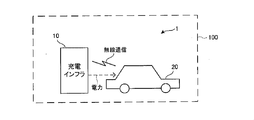
- FIG. 1 is a conceptual diagram showing the overall configuration of the charging system according to the present embodiment
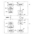
- FIG. 2 is a block diagram showing the main part of the charging system according to the present embodiment.
- the charging system 1 constitutes one charging base (so-called charging stand) in a parking lot 100 such as a parking lot of a building of a company or a municipality or a parking lot of a shopping center.
- the charging system 1 includes a charging infrastructure 10 (hereinafter referred to as “charging infrastructure” as appropriate).
- charging infrastructure 10 hereinafter referred to as “charging infrastructure” as appropriate.
- one charging infrastructure 10 is provided for one parking space.
- the “charging infrastructure” according to the present embodiment is an example of the “charging device” according to the present invention.
- the charging system 1 may include a plurality of charging infrastructures 10.
- the charging infrastructure 10 includes a connection management unit 110, a packet generation / analysis unit 120, a packet transmission / reception unit 130, a power transmission control unit 140, a main circuit 150, and a coil 160.
- the vehicle 20 such as an electric vehicle or a hybrid vehicle includes a connection management unit 210, a packet generation / analysis unit 220, a packet transmission / reception unit 230, a charge control unit 240, for example, a battery 250 such as a lithium ion battery or a nickel hydrogen battery, and A coil 260 is provided.
- the “battery 250” according to the present invention is an example of the “rechargeable battery” according to the present invention.
- the charging infrastructure 10 is configured to be able to supply electric power from the outside to the battery 250 mounted on the vehicle 20 based on, for example, mutual induction of electromagnetic induction. Specifically, at the time of power feeding, the magnetic flux in the coil 160 between the coil 160 that is a coil on the power feeding side (that is, the charging infrastructure 10 side) and the coil 260 that is the coil on the charging side (that is, the vehicle 20 side). Due to the formation of an induced electromotive force in the coil 260 due to the formation, electric power is transmitted from the coil 160 to the coil 260.
- the distance between the coil 160 of the charging infrastructure 10 and the coil 260 mounted on the vehicle 20 at the time of power feeding is, for example, 10 to 25 cm (centimeter).
- the power transmission control unit 140 of the charging infrastructure 10 controls a main circuit including, for example, a converter, an inverter, a rectifier, a switch, and the like at the time of power feeding so that an appropriate magnetic flux is formed in the coil 160.
- the power transmission control unit 140 further sends information relating to charging such as an output possible voltage value, a current output voltage value, a current charging current value, and the like (hereinafter referred to as “infrastructure-side charging control information” as appropriate) to the connection management unit 110. Send to.
- the charging control unit 240 of the vehicle 20 controls the battery 250 and its peripheral circuits (not shown) and the like during power feeding so that the battery 250 is appropriately charged.
- the charging control unit 240 further transmits information related to charging such as a remaining battery capacity and a charging current command value (hereinafter, referred to as “vehicle-side charging control information” as appropriate) to the connection management unit 210.
- the connection management unit 110 of the charging infrastructure 10 controls the packet generation / analysis unit 120 so that various types of information including the infrastructure-side charging control information are packetized and transmitted to the vehicle 20 via the packet transmission / reception unit 130.
- the connection management unit 110 further controls the packet generation / analysis unit 120 so as to restore the original information from the packet received via the packet transmission / reception unit 130.
- connection management unit 210 of the vehicle 20 controls the packet generation / analysis unit 220 to packetize various types of information including the vehicle-side charging control information and transmit the information to the charging infrastructure 10 via the packet transmission / reception unit 230. To do.
- the connection management unit 210 further controls the packet generation / analysis unit 220 to restore the original information from the packet received via the packet transmission / reception unit 230.
- FIG. 3 is an example of a UDP (User Datagram Protocol) packet format
- FIG. 4 is an example of a MAC (Media Access Control) frame format
- FIG. 5 is an example of an IP (Internet Protocol) packet format.
- the numerical values in FIGS. 3 to 5 indicate the size. Specifically, for example, “sequence number” in FIG. 3 is “8” bytes, “destination ID” is “6” bytes, and “charge command / report data” is “0” or “20”. Or “40” bytes.
- the infrastructure side charging control information or the vehicle side charging control information is included in the UDP packet as “charging command / report data”. Is added. Specifically, for example, 40 bytes of “charge command data” is added to a packet transmitted from the vehicle 20 to the charging infrastructure 10 during non-contact charging, as shown in FIG. On the other hand, 20-byte “charge report data” is added to the packet transmitted from the charging infrastructure 10 to the vehicle 20 as shown in FIG. At times other than non-contact charging, as shown in FIG. 5 (a), a packet to which “charge command / report data” is not added is transmitted.
- the charging infrastructure 10 is the transmission side and the vehicle 20 is the reception side.
- the “connection management unit 110”, “packet generation / analysis unit 120”, “packet transmission / reception unit 130”, “connection management unit 210”, “ The “packet generation / analysis unit 220” and the “packet transmission / reception unit 230” may be read each other.
- connection management unit 110 of the charging infrastructure 10 (transmission side) initializes a sequence number given to a packet to be transmitted and initializes a transmission period (for example, 100 ms) (step S101). ).
- the connection management unit 110 controls the packet generation / analysis unit 120 so as to generate a packet to be transmitted (step S102).
- the generated packet is a packet without the “charging instruction / report data” (see FIG. 5A).
- the generated packet is a packet to which “charge report data” is added (see FIG. 5C).
- the generated packet is a packet to which “charge command data” is added (see FIG. 5B).
- connection management unit 110 controls the packet generation / analysis unit 120 to store the generated packet in a multiplex transmission buffer (not shown) (step S103). Subsequently, the connection management unit 110 determines whether or not the number of times the packet stored in step S103 is transmitted satisfies the number of times of multiplex transmission (for example, 5 times) (step S104).
- step S104 When it is determined that the number of times the packet stored in step S103 has been transmitted satisfies the number of times of multiplex transmission (step S104: Yes), the connection management unit 110 executes a process of step S108 described later.
- step S104 determines that the vehicle 20 (receiving side) Then, the packet generation / analysis unit 120 is controlled to transmit the stored packet via the packet transmission / reception unit 130 (step S105).
- connection management unit 110 determines whether or not the transmission period has ended (step S106). When it is determined that the transmission period has not ended (step S106: No), the connection management unit 110 executes step S104.
- connection management unit 110 is stored in the multiplex transmission buffer without waiting for a reception confirmation (so-called “ACK”) from the vehicle 20 (reception side) until the transmission period ends or the multiplex transmission count is satisfied.
- ACK reception confirmation
- the packet generation / analysis unit 120 is controlled so that the same packet as the received packet is transmitted to the vehicle 20 a plurality of times (see FIG. 6A).
- FIG. 6 is a conceptual diagram showing the concept of packet transmission / reception in this embodiment.
- numerical values “0”, “1”, and “2” indicate sequence numbers assigned to the packets
- alphabets “A”, “B”, and “X” indicate data contents. .
- step S106 When it is determined in the process of step S106 that the transmission period has ended (step S106: Yes), the connection management unit 110 determines that the number of times the packet stored in step S103 has been transmitted satisfies the number of times of multiplex transmission. It is determined whether or not (step S107).
- step S107 When it is determined that the number of times the packet stored in step S103 is transmitted does not satisfy the number of times of multiplex transmission (that is, time-out) (step S107: No), the connection management unit 110 performs predetermined abnormality processing. Execute. Specifically, for example, whether the connection management unit 110 could not transmit due to insufficient bandwidth due to a large amount of all communication data, or could not transmit because the communication path could not be maintained due to interference from radio waves outside the system. , And a return operation is performed according to the determination result, or the process is terminated as it is.
- step S107 when it is determined that the number of times the packet stored in step S103 has been transmitted satisfies the number of times of multiplex transmission (step S107: Yes), the connection management unit 110 converts the packet stored in the multiplex transmission buffer. Delete (step S108) and increment the sequence number (step S109). As a result, the sequence number assigned to the packet generated in the next step S102 is changed from the sequence number assigned to the packet transmitted this time.
- connection management unit 210 of the vehicle 20 (reception side) initializes a sequence number recorded in a memory (not shown) (step S201), and then receives a packet via the packet transmission / reception unit 230. If so (step S202), it is determined whether or not charging control information (that is, charging command data or charging report data) is added (step S203). When it is determined that the charging control information is not added (step S203: No), the connection management unit 210 executes a process of step S206 described later.
- charging control information that is, charging command data or charging report data
- connection management unit 210 separates the charging control information from the received packet (in other words, the charging control information from the received packet). (Step S204). Subsequently, the connection management unit 210 transmits the disconnected charge control information to the charge control unit 240 (step S205). If the charging infrastructure 10 is the receiving side, the separated charging control information is transmitted to the power transmission control unit 140.
- connection management unit 210 determines whether or not the packet received in step S202 is the first packet after the sequence number is reset in the process of step S201 (step S206).
- connection management unit 210 When it is determined that the packet is the first packet (step S206: Yes), the connection management unit 210 records the sequence number given to the received packet in a memory (not shown) and resets the multiple packet counter. (Step S213), and a standby state is entered until the next packet is received.
- connection management unit 210 determines whether the sequence number of the packet received this time is equal to the sequence number of the packet received last time (step S206). S207).
- connection management unit 210 increments the multiplex packet counter (step S208). Subsequently, the connection management unit 210 determines whether or not the content of the currently received packet is equal to the content of the previously received packet (step S209).
- step S209: No the connection management unit 210 executes the process of step S301 described later (see FIG. 9).
- the connection management unit 210 sets the value of the multiplex packet counter to a predetermined multiplex transmission number (for example, it is determined whether or not “5”) has been reached (step S210).
- a predetermined multiplex transmission number For example, it is determined whether or not “5” has been reached (step S210).
- the connection management unit 210 enters a standby state until the next packet is received.
- connection management unit 210 When it is determined that the value of the multiplex packet counter has not reached the predetermined multiplex transmission number (step S210: No), the connection management unit 210 multiplex-transmits a predetermined reception waiting time (that is, a predetermined packet). It is determined whether or not a period having the same length as the period (for example, 100 ms) has elapsed (step S211). When it is determined that the predetermined reception waiting time has not elapsed (step S211: No), the connection management unit 210 enters a standby state until the next packet is received. When it is determined that the predetermined reception waiting time has elapsed (for example, as shown in FIG. 6B, when a predetermined number of packets are not received even after the predetermined time has elapsed) (step S211: Yes), connection management Unit 210 determines whether or not the multiplex packet counter is zero (step S212).
- step S212: No When it is determined that the multiplex packet counter is not zero (that is, when one of the multiplexed packets is received) (step S212: No), the connection management unit 210 is in a standby state until the next packet is received. It becomes. On the other hand, when it is determined that the multiplex packet counter is zero (that is, when no multiplex packet is received) (step S212: Yes), the connection management unit 210 performs the process of step S301 described later. (See FIG. 9).
- step S207 If it is determined in step S207 that the sequence number of the currently received packet is different from the sequence number of the previously received packet (step S207: No), the connection management unit 210 It is determined whether or not the sequence number and the sequence number of the packet received this time are consecutive (step S214).
- step S214: Yes When it is determined that the sequence number of the previously received packet and the sequence number of the currently received packet are consecutive (step S214: Yes), the connection management unit 210 executes the process of step S213 above. To do. On the other hand, it is determined that the sequence number of the packet received last time and the sequence number of the packet received this time are not consecutive (see “1: A” and “0: A” in FIG. 6C). If it is found (step S214: No), the connection management unit 210 executes the process of step S301 (see FIG. 9) described later.
- connection management unit 210 of the vehicle 20 (reception side) initializes the number of times that short-term communication abnormality has occurred continuously (step S301). Subsequently, the connection management unit 210 transmits a charging stop command to the charging control unit 240 and the charging infrastructure 10 (step S302), and notifies the user of a short-term charging interruption.
- the connection management unit 110 transmits a charging stop command to the power transmission control unit 140 and the vehicle 20.
- connection management unit 210 determines whether or not a predetermined recovery waiting time has elapsed (step S304). When it is determined that the predetermined recovery waiting time has not elapsed (step S304: No), the connection management unit 210 executes the process of step S304 again (that is, the connection management unit 210 performs the predetermined recovery waiting time). Until the time elapses).
- connection management unit 210 transmits a transmission restart command to the charging infrastructure 10 (step S305). If the charging infrastructure 10 is on the receiving side, the connection management unit 110 transmits a transmission restart command to the vehicle 20.
- connection management unit 210 determines whether or not the communication state has been recovered (step S306).
- connection management unit 210 When it is determined that the communication state does not recover (step S306: No), the connection management unit 210 adds the continuous number of short-term communication abnormalities (typically increases by 1) (step S307). Subsequently, the connection management unit 210 determines whether or not the number of recharging times exceeds a specified number (step S308).
- step S308 Yes
- the connection management unit 210 notifies the user of the suspension of charging (step S310), and executes a predetermined charging suspension process. As a result, the non-contact charging between the charging infrastructure 10 and the vehicle 20 is completely stopped.
- connection management unit 210 determines whether or not the number of consecutive communication abnormalities exceeds the specified number of times (step S309). ).
- step S309: No If it is determined that the number of detected communication abnormalities does not exceed the prescribed number (step S309: No), the connection management unit 210 executes the process of step S304. On the other hand, when it is determined that the communication abnormality detection count has exceeded the specified count (step S309: Yes), the connection management unit 210 executes the process of step S310.
- step S306 when it is determined that the communication state has been recovered (step S306: Yes), the connection management unit 210 resets the continuous number of short-term communication abnormalities (step S311) and sets the number of times of charge recovery. Add (typically increase by 1) (step S312).
- connection management unit 210 transmits a charge resumption command to the charge control unit 240 and the charging infrastructure 10 (step S313).
- the connection management unit 110 transmits a charge resumption command to the power transmission control unit 140 and the vehicle 20.
- connection management unit 210 notifies the user of resumption of charging (step S314), and resumes a predetermined charging operation.
- connection management unit 110” and the “connection management unit 210” according to the present embodiment are examples of the “control unit” according to the first communication control device of the present invention.
- the “connection management unit 110” and the “connection management unit 210” according to the present embodiment are examples of the “control unit” according to the third communication control apparatus of the present invention.
- the “connection management unit 110” and the “connection management unit 210” according to the present embodiment are examples of the “first communication unit” and the “second communication unit” according to the second communication control device of the present invention, respectively. .
- the “sequence number” according to the present embodiment is an example of “identification information” according to the present invention.
- “Charge command / report data”, “charge command data”, and “charge report data” according to the present embodiment are examples of “control information”, “first control information”, and “second control information” according to the present invention. It is.
- the “charge stop command” and the “charge restart command” according to the present embodiment are examples of the “charge stop signal” and the “charge restart signal” according to the present invention, respectively.
- an electromagnetic induction type charging system is used as the charging system 1.
- the present invention is not limited to the electromagnetic dielectric type charging system, and may be, for example, a radio wave receiving type or a magnetic field coupling resonance type.
- the present invention can also be applied to a system that employs various non-contact charging methods.
- SYMBOLS 1 ... Charging system, 10 ... Charging infrastructure, 20 ... Vehicle, 100 ... Parking lot, 110, 210 ... Connection management part, 120, 220 ... Packet generation and analysis part, 130, 230 ... Packet transmission / reception part, 140 ... Power transmission control part , 150 ... main circuit, 160, 260 ... coil, 240 ... charge control unit, 250 ... battery
Landscapes
- Engineering & Computer Science (AREA)
- Computer Networks & Wireless Communication (AREA)
- Signal Processing (AREA)
- Electric Propulsion And Braking For Vehicles (AREA)
Abstract
通信制御装置(110、210)は、車両(20)に搭載された充電池(250)に対して非接触充電を実行可能な充電装置(10)と、該車両との間における非接触充電に係る制御情報の授受を制御する通信制御装置である。該通信制御装置は、(i)制御情報のうち一の制御情報である第1制御情報を示す第1パケットと同一のパケットを、充電装置及び車両の一方から充電装置及び車両の他方へ、前記他方から前記一方への受信確認を待つことなく、複数回送信すると共に、(ii)制御情報のうち、第1制御情報の次に送信される制御情報である第2制御情報を示す第2パケットを、前記一方から前記他方へ送信する際に、第2パケットに係る当該パケットを他のパケットから識別するための識別情報を、第1パケットに係る識別情報から変更する制御手段(110、210)を備える。
Description
本発明は、二次電池を搭載する車両と、該二次電池を充電可能な充電装置と、の間における通信を制御する通信制御装置及び方法並びにコンピュータプログラムの技術分野に関する。
この種の装置が適用されるシステムとして、例えば給電スタンドと車両との間で、無線により給電に関する情報が授受される非接触給電システムが提案されている(特許文献1参照)。
尚、無線ネットワークにおけるパケットロスの問題を解決する方法として、送信装置が、同じパケットを時間差をつけて複数回ネットワークに送信し、受信装置がパケット内のシーケンスナンバーをもとに同一パケットの複数受信による冗長パケットを廃棄し、一つのパケットだけをデータストリームの組み立て直しに用いる方法が提案されている(特許文献2参照)。
或いは、同一パケットを伝送路を介して受信局へ複数回送出し、受信局のパケット受信部が受信したパケットの内容を比較し多数決方式により適正パケットを選択する方法が提案されている(特許文献3参照)。
上記特許文献1に記載のシステムでは、例えばパケットロス等に起因して給電に関する情報が適切に授受されない可能性がある。すると、非接触給電が適切に行われない可能性があるという技術的問題点がある。
本発明は、例えば上記問題点に鑑みてなされたものであり、充電装置及び車両間における通信を適切に行うことができる通信制御装置及び方法、並びにコンピュータプログラムを提案することを課題とする。
本発明の第1の通信制御装置は、上記課題を解決するために、車両に搭載された充電池に対して非接触充電を実行可能な充電装置と、前記車両との間における前記非接触充電に係る制御情報の授受を制御する通信制御装置であって、(i)前記制御情報のうち一の制御情報である第1制御情報を示す第1パケットと同一のパケットを、前記充電装置及び前記車両の一方から前記充電装置及び前記車両の他方へ、前記他方から前記一方への受信確認を待つことなく、複数回送信すると共に、(ii)前記制御情報のうち、前記第1制御情報の次に送信される制御情報である第2制御情報を示す第2パケットを、前記一方から前記他方へ送信する際に、前記第2パケットに係る当該パケットを他のパケットから識別するための識別情報を、前記第1パケットに係る識別情報から変更する制御手段を備える。
本発明の第1の通信制御装置によれば、当該通信制御装置は、例えばハイブリッド自動車、電気自動車等である車両に搭載された、例えばリチウムイオン電池、ニッケル水素電池等の充電池に対して、非接触充電を実行可能な充電装置と、該車両との間における該非接触充電に係る制御情報の授受を制御する。
ここで、「非接触充電」とは、無線で電力を供給し、充電池を充電する技術を意味する。非接触充電の具体的な方式としては、例えば電磁誘導方式、マイクロ波無線式(電波受信方式)、磁場結合共鳴方式等がある。尚、非接触充電の詳細については、本発明の要旨との相関が薄いため、ここではその詳細を割愛する。
例えばメモリ、プロセッサ等を備えてなる制御装置は、(i)制御情報のうち一の制御情報である第1制御情報を示す第1パケットと同一のパケットを、充電装置及び車両の一方から充電装置及び車両の他方へ、該他方から該一方への受信確認を待つことなく、複数回送信する。
制御装置は、更に、(ii)制御情報のうち、第1制御情報の次に送信される制御情報である第2制御情報を示す第2パケットを、前記一方から前記他方へ送信する際に、該第2パケットに係る当該パケットを他のパケットから識別するための識別情報を、第1パケットに係る識別情報から変更する。
充電装置及び車両の他方(即ち、受信側)は、仮にパケットロスが発生したとしても、送信された複数の同一のパケットの全てが失われるような障害が発生しない限り、元の制御情報を復元することができる。尚、充電装置及び車両の他方は、パケットロスが発生しない場合には、受信した複数の同一のパケットから一つのパケットを選択し元の制御情報を復元する。
この結果、充電装置及び車両間における通信の信頼性を向上させることができる。従って、本発明の第1の通信制御装置によれば、充電装置及び車両間における通信を適切に実行することができる。
本発明の第2の通信制御装置は、上記課題を解決するために、車両に搭載された充電池に対して非接触充電を実行可能な充電装置と、前記車両との間における前記非接触充電に係る制御情報の授受を制御する通信制御装置であって、前記充電装置において前記制御情報の授受を制御する第1通信制御手段と、前記車両において前記制御情報の授受を制御する第2通信制御手段と、を備え、前記充電装置及び前記車両の一方から、前記充電装置及び前記車両の他方へ、前記制御情報が送信される際に、前記第1通信制御手段及び前記第2通信制御手段のうち前記一方に対応する通信制御手段は、(i)前記制御情報のうち一の制御情報である第1制御情報を示し、他のパケットから識別するための識別情報を有する第1パケットと同一のパケットを、前記一方から前記他方へ、前記他方から前記一方への受信確認を待つことなく、複数回送信すると共に、(ii)前記制御情報のうち、前記第1制御情報の次に送信される制御情報である第2制御情報を示す第2パケットを、前記一方から前記他方へ送信する際に、前記第2パケットに係る識別情報を、前記第1パケットに係る前記識別情報から変更し、前記第1通信制御手段及び前記第2通信制御手段のうち前記他方に対応する通信制御手段は、(i)所定時間内にパケットが受信されない場合、又は、(ii)前記識別情報が同一であるにもかかわらず互いに異なる内容を示すパケットが受信された場合に、前記非接触充電の中止を示す信号である充電中止信号を出力する。
本発明の第2の通信制御装置によれば、当該通信制御装置は、充電装置において制御情報の授受を制御する第1通信制御手段と、車両において制御情報の授受を制御する第2通信制御手段とを備えて構成されている。
第1通信制御手段及び第2通信制御手段のうち一方(即ち、送信側)は、(i)制御情報のうち一の制御情報である第1制御情報を示し、他のパケットから識別するための識別情報を有する第1パケットと同一のパケットを、充電装置及び車両の一方から充電装置及び車両の他方へ、充電装置及び車両の他方から充電装置及び車両の一方への受信確認を待つことなく、複数回送信する。
第1通信制御装置及び第2通信制御装置のうち一方は、更に、(ii)制御情報のうち、第1制御情報の次に送信される制御情報である第2制御情報を示す第2パケットを、充電装置及び車両の一方から充電装置及び車両の他方へ送信する際に、第2パケットに係る識別情報を、第1パケットに係る識別情報から変更する。
他方、第1通信制御手段及び第2通信制御手段のうち他方(即ち、受信側)は、(i)所定時間(例えば、100ms(ミリ秒))内にパケットが受信されない場合、又は、(ii)識別情報が同一であるにもかかわらず互いに異なる内容を示すパケットが受信された場合に、非接触充電の中止を示す信号である充電中止信号を出力する。
この結果、充電装置及び車両間における通信の信頼性を向上させることができる。加えて、通信障害が発生したとしても、速やかに非接触充電が中止されるので、充電装置及び車両の損傷を防止することができる。
本発明の第3の通信制御装置は、上記課題を解決するために、車両に搭載された充電池に対して非接触充電を実行可能な充電装置と、前記車両との間における前記非接触充電に係る制御情報の授受を制御する通信制御装置であって、(i)所定時間内にパケットが受信されない場合、又は、(ii)一のパケットを他のパケットから識別するための識別情報が同一であるにもかかわらず互いに異なる内容を示すパケットが受信された場合に、前記非接触充電の中止を示す信号である充電中止信号を出力する制御手段を備える。
本発明の第3の通信制御装置によれば、例えばメモリ、プロセッサ等を備えてなる制御手段は、(i)所定時間内にパケットが受信されない場合、又は、(ii)一のパケットを他のパケットから識別するための識別情報が同一であるにもかかわらず互いに異なる内容を示すパケットが受信された場合に、非接触充電の中止を示す信号である充電中止信号を出力する。
この結果、本発明の第3の通信制御装置によれば、仮に通信障害が発生したとしても速やかに非接触充電が中止されるので、充電装置及び車両の損傷を防止することができる。
本発明の第2の通信制御装置又は第3の通信制御装置の一態様では、前記制御手段は、前記充電中止信号を出力した後の前記所定時間内にパケットが受信された場合、且つ、前記充電中止信号を出力した後に、前記充電中止信号を出力する直前に受信したパケットに係る識別情報と同一の識別情報を有するパケットが受信された場合、前記非接触充電の再開を示す信号である充電再開信号を出力する。
この態様によれば、通信のごく短期間の中断であれば、通信が回復した際に充電を再開することができるので、実用上非常に有利である。
本発明の第1の通信制御方法は、上記課題を解決するために、車両に搭載された充電池に対して非接触充電を実行可能な充電装置と、前記車両との間における前記非接触充電に係る制御情報の授受を制御する通信制御方法であって、(i)前記制御情報のうち一の制御情報である第1制御情報を示す第1パケットと同一のパケットを、前記充電装置及び前記車両の一方から前記充電装置及び前記車両の他方へ、前記他方から前記一方への受信確認を待つことなく、複数回送信すると共に、(ii)前記制御情報のうち、前記第1制御情報の次に送信される制御情報である第2制御情報を示す第2パケットを、前記一方から前記他方へ送信する際に、前記第2パケットに係る当該パケットを他のパケットから識別するための識別情報を、前記第1パケットに係る識別情報から変更する制御工程を備える。
本発明の第1の通信制御方法によれば、本発明の第1の通信制御装置と同様に、充電装置及び車両間における通信を適切に実行することができる。
本発明の第1のコンピュータプログラムは、上記課題を解決するために、コンピュータを、上述した本発明の第1の通信制御装置として機能させる。
本発明の第1のコンピュータプログラムによれば、当該コンピュータプログラムを格納するCD-ROM(Compact Disc Read Only Memory)、DVD-ROM(DVD Read Only Memory)等の記録媒体から、当該コンピュータプログラムを、第1の通信制御装置に備えられたコンピュータに読み込んで実行させれば、或いは、当該コンピュータプログラムを通信手段を介してダウンロードさせた後に実行させれば、上述した本発明の第1の通信制御装置を比較的容易にして実現できる。これにより、上述した本発明の第1の通信制御装置の場合と同様に、充電装置及び車両間における通信を適切に実行することができる。
本発明の第2の通信制御装置は、上記課題を解決するために、本発明の車両に搭載された充電池に対して非接触充電を実行可能な充電装置と、前記車両との間における前記非接触充電に係る制御情報の授受を制御し、前記充電装置において前記制御情報の授受を制御する第1通信制御手段と、前記車両において前記制御情報の授受を制御する第2通信制御手段と、を備える充電制御装置における通信制御方法であって、前記充電装置及び前記車両の一方から、前記充電装置及び前記車両の他方へ、前記制御情報が送信される際に、前記第1通信制御手段及び前記第2通信制御手段のうち前記一方に対応する通信制御手段が、(i)前記制御情報のうち一の制御情報である第1制御情報を示し、他のパケットから識別するための識別情報を有する第1パケットと同一のパケットを、前記一方から前記他方へ、前記他方から前記一方への受信確認を待つことなく、複数回送信すると共に、(ii)前記制御情報のうち、前記第1制御情報の次に送信される制御情報である第2制御情報を示す第2パケットを、前記一方から前記他方へ送信する際に、前記第2パケットに係る識別情報を、前記第1パケットに係る前記識別情報から変更する第1工程と、前記第1通信制御手段及び前記第2通信制御手段のうち前記他方に対応する通信制御手段が、(i)所定時間内にパケットが受信されない場合、又は、(ii)前記識別情報が同一であるにもかかわらず互いに異なる内容を示すパケットが受信された場合に、前記非接触充電の中止を示す信号である充電中止信号を出力する第2工程と、を備える。
本発明の第2の通信制御方法によれば、本発明の第2の通信制御装置と同様に、充電装置及び車両間における通信の信頼性の向上、及び充電装置及び車両の損傷の防止を、図ることができる。尚、本発明の第2の通信制御方法においても、上述した本発明の第2通信制御装置における各種態様と同様の各種態様を採ることが可能である。
本発明の第2のコンピュータプログラムは、上記課題を解決するために、コンピュータを、上述した本発明の第2の通信制御装置(但し、その各種態様を含む)を構成する前記第1通信制御手段及び前記第2通信制御手段のうち一方として機能させる。
本発明の第2のコンピュータプログラムによれば、当該コンピュータプログラムを格納するCD-ROM、DVD-ROM等の記録媒体から、当該コンピュータプログラムを、第2の通信制御装置に備えられたコンピュータに読み込んで実行させれば、或いは、当該コンピュータプログラムを通信手段を介してダウンロードさせた後に実行させれば、上述した本発明の第2の通信制御装置を構成する第1通信制御装置及び第2通信制御手段のうち一方を比較的容易にして実現できる。これにより、上述した本発明の第2の通信制御装置の場合と同様に、充電装置及び車両間における通信の信頼性の向上、及び充電装置及び車両の損傷の防止を、図ることができる。
本発明の作用及び他の利得は次に説明する実施するための形態から明らかにされる。
以下、本発明に係る通信制御装置の実施形態について、図面に基づいて説明する。
(充電システムの構成)
本実施形態に係る充電システムの構成を図1及び図2を参照して説明する。図1は、本実施形態に係る充電システムの全体構成を示す概念図であり、図2は、本実施形態に係る充電システムの要部を示すブロック図である。
本実施形態に係る充電システムの構成を図1及び図2を参照して説明する。図1は、本実施形態に係る充電システムの全体構成を示す概念図であり、図2は、本実施形態に係る充電システムの要部を示すブロック図である。
図1において、充電システム1は、例えば企業や自治体のビルの駐車場、或いはショッピングセンタの駐車場等の駐車場100において、一つの充電拠点(所謂、充電スタンド)を構成している。充電システム1は、充電インフラストラクチャ10(以降、適宜、“充電インフラ”と称する)を備えて構成されている。ここで、充電インフラ10は、一つの駐車スペースに対して一つ設けられている。
本実施形態に係る「充電インフラ」は、本発明に係る「充電装置」の一例である。尚、充電システム1は、充電インフラ10を複数備えて構成されていてもよい。
図2において、充電インフラ10は、接続管理部110、パケット生成・解析部120、パケット送受信部130、送電制御部140、主回路150及びコイル160を備えて構成されている。
例えば電気自動車、ハイブリッド自動車等である車両20は、接続管理部210、パケット生成・解析部220、パケット送受信部230、充電制御部240、例えばリチウムイオン電池、ニッケル水素電池等であるバッテリ250、及びコイル260を備えて構成されている。尚、本発明に係る「バッテリ250」は、本発明に係る「充電池」の一例である。
充電インフラ10は、例えば電磁誘導の相互誘導作用に基づき、外部から非接触で電力を、車両20に搭載されたバッテリ250に供給可能に構成されている。具体的には、給電時に、給電側(即ち、充電インフラ10側)のコイルであるコイル160と、充電側(即ち、車両20側)のコイルであるコイル260との間で、コイル160における磁束形成に起因してコイル260に誘導起電力が生じることによって、コイル160からコイル260に電力が伝送されるように構成されている。
尚、給電時における、充電インフラ10のコイル160と、車両20に搭載されたコイル260と、の間の距離は、例えば10~25cm(センチメートル)等である。
充電インフラ10の送電制御部140は、コイル160に適切な磁束が形成されるように、例えばコンバータ、インバータ、整流器、スイッチ等を備えてなる主回路を、給電時に制御する。送電制御部140は、更に、例えば出力可能電圧値、現在出力電圧値、現在充電電流値等の充電に係る情報(以降、適宜“インフラ側充電制御情報”と称する)を、接続管理部110に対して送信する。
他方、車両20の充電制御部240は、バッテリ250が適切に充電されるように、バッテリ250及びその周辺回路(図示せず)等を、給電時に制御する。充電制御部240は、更に、例えば電池残存容量、充電電流指令値等の充電に係る情報(以降、適宜“車両側充電制御情報”と称する)を、接続管理部210に対して送信する。
充電インフラ10の接続管理部110は、インフラ側充電制御情報を含む各種情報をパケット化して、パケット送受信部130を介して車両20に送信するように、パケット生成・解析部120を制御する。接続管理部110は、更に、パケット送受信部130を介して受信されたパケットから、元の情報を復元するようにパケット生成・解析部120を制御する。
同様に、車両20の接続管理部210は、車両側充電制御情報を含む各種情報をパケット化して、パケット送受信部230を介して充電インフラ10に送信するように、パケット生成・解析部220を制御する。接続管理部210は、更に、パケット送受信部230を介して受信されたパケットから、元の情報を復元するようにパケット生成・解析部220を制御する。
ここで、充電インフラ10と車両20との間で授受されるパケットについて、図3乃至図5を参照して説明する。図3は、UDP(User Datagram Protocol)パケットフォーマットの一例であり、図4は、MAC(Media Access Control)フレームフォーマットの一例であり、図5は、IP(Internet Protocol)パケットフォーマットの一例である。
尚、図3乃至図5における数値は、サイズを示している。具体的には例えば、図3における「シーケンス番号」は“8”バイトであり、「送信先ID」は“6”バイトであり、「充電指令/報告データ」は、“0”又は“20”又は“40”バイトである。
本実施形態では無線伝送を前提としているため、図3に示すようなUDPパケットが採用される。該UDPパケットは、図4に示すように、MACフレームの“Frame Body”に、“IP Header”と共に格納される。
充電インフラ10から車両20に対して電力が供給される際(即ち、非接触充電時)には、UDPパケットに、「充電指令/報告データ」として、インフラ側充電制御情報又は車両側充電制御情報が付加される。具体的には例えば、非接触充電時に、車両20から充電インフラ10に対して送信されるパケットには、図5(b)に示すように、40バイトの「充電指令データ」が付加される。他方、充電インフラ10から車両20に対して送信されるパケットには、図5(c)に示すように、20バイトの「充電報告データ」が付加される。尚、非接触充電時以外では、図5(a)に示すように、「充電指令/報告データ」が付加されていないパケットが送信される。
(パケット送受信)
充電インフラ10及び車両20間においてパケットが送受信される際の、充電インフラ10及び車両20の動作について、図6乃至図9を参照して説明する。尚、本実施形態では、説明の便宜上、充電インフラ10を送信側、車両20を受信側とする。車両20が送信側となり、充電インフラ10が受信側となる場合は、「接続管理部110」、「パケット生成・解析部120」及び「パケット送受信部130」と、「接続管理部210」、「パケット生成・解析部220」及び「パケット送受信部230」と、を相互に読み替えればよい。
充電インフラ10及び車両20間においてパケットが送受信される際の、充電インフラ10及び車両20の動作について、図6乃至図9を参照して説明する。尚、本実施形態では、説明の便宜上、充電インフラ10を送信側、車両20を受信側とする。車両20が送信側となり、充電インフラ10が受信側となる場合は、「接続管理部110」、「パケット生成・解析部120」及び「パケット送受信部130」と、「接続管理部210」、「パケット生成・解析部220」及び「パケット送受信部230」と、を相互に読み替えればよい。
(送信側動作)
図7において、先ず、充電インフラ10(送信側)の接続管理部110は、送信されるパケットに付与されるシーケンス番号を初期化すると共に、送信期間を初期化する(例えば100ms等)(ステップS101)。
図7において、先ず、充電インフラ10(送信側)の接続管理部110は、送信されるパケットに付与されるシーケンス番号を初期化すると共に、送信期間を初期化する(例えば100ms等)(ステップS101)。
次に、接続管理部110は、送信されるパケットを生成するように、パケット生成・解析部120を制御する(ステップS102)。ここで、充電インフラ10及び車両20間において非接触充電が実行されていない場合、生成されるパケットは、「充電指令/報告データ」のないパケットとなる(図5(a)参照)。他方、非接触充電が実行されている場合、生成されるパケットは、「充電報告データ」が付加されたパケットとなる(図5(c)参照)。尚、車両20が送信側であり、且つ非接触充電が実行されている場合、生成されるパケットは、「充電指令データ」が付加されたパケットとなる(図5(b)参照)。
次に、接続管理部110は、生成されたパケットを多重送信バッファ(図示せず)へ格納するように、パケット生成・解析部120を制御する(ステップS103)。続いて、接続管理部110は、上記ステップS103で格納されたパケットが送信された回数が、多重送信回数(例えば5回)を満たしたか否かを判定する(ステップS104)。
上記ステップS103で格納されたパケットが送信された回数が、多重送信回数を満たしたと判定された場合(ステップS104:Yes)、接続管理部110は、後述するステップS108の処理を実行する。
他方、上記ステップS103で格納されたパケットが送信された回数が、多重送信回数を満たしていないと判定された場合(ステップS104:No)、接続管理部110は、車両20(受信側)に対して、格納されたパケットを、パケット送受信部130を介して送信するように、パケット生成・解析部120を制御する(ステップS105)。
続いて、接続管理部110は、送信期間が終了したか否かを判定する(ステップS106)。送信期間が終了していないと判定された場合(ステップS106:No)、接続管理部110は、上記ステップS104を実行する。
つまり、接続管理部110は、送信期間が終了するまで、又は多重送信回数を満たすまで、車両20(受信側)からの受信確認(所謂“ACK”)を待つことなく、多重送信バッファに格納されたパケットと同一のパケットを複数回、車両20に対して送信するように、パケット生成・解析部120を制御する(図6(a)参照)。
尚、図6は、本実施形態におけるパケット送受信の概念を示す概念図である。図6において、数値“0”、“1”及び“2”は、パケットに付与されたシーケンス番号を示しており、アルファベット“A”、“B”及び“X”は、データ内容を示している。
上記ステップS106の処理において、送信期間が終了したと判定された場合(ステップS106:Yes)、接続管理部110は、上記ステップS103で格納されたパケットが送信された回数が、多重送信回数を満たしたか否かを判定する(ステップS107)。
上記ステップS103で格納されたパケットが送信された回数が、多重送信回数を満たしていないと判定された場合(即ち、タイムアウト)(ステップS107:No)、接続管理部110は、所定の異常処理を実行する。具体的には例えば、接続管理部110は、全通信データ量が多いことによる帯域不足により送信できなかったのか、又は、システム外の電波による干渉により通信経路が維持できずに送信できなかったのか、を判定し、判定結果に応じて復帰動作を行う、又は、そのまま処理を終了する。
他方、上記ステップS103で格納されたパケットが送信された回数が、多重送信回数を満たしたと判定された場合(ステップS107:Yes)、接続管理部110は、多重送信バッファに格納されているパケットを削除して(ステップS108)、シーケンス番号をインクリメントする(ステップS109)。この結果、次回ステップS102の処理において生成されるパケットに付与されるシーケンス番号が、今回送信されたパケットに付与されたシーケンス番号から変更される。
(受信側動作)
図8において、車両20(受信側)の接続管理部210は、メモリ(図示せず)に記録されているシーケンス番号を初期化(ステップS201)した後に、パケット送受信部230を介してパケットが受信されると(ステップS202)、充電制御情報(即ち、充電指令データ又は充電報告データ)が付加されているか否かを判定する(ステップS203)。充電制御情報が付加されていないと判定された場合(ステップS203:No)、接続管理部210は、後述するステップS206の処理を実行する。
図8において、車両20(受信側)の接続管理部210は、メモリ(図示せず)に記録されているシーケンス番号を初期化(ステップS201)した後に、パケット送受信部230を介してパケットが受信されると(ステップS202)、充電制御情報(即ち、充電指令データ又は充電報告データ)が付加されているか否かを判定する(ステップS203)。充電制御情報が付加されていないと判定された場合(ステップS203:No)、接続管理部210は、後述するステップS206の処理を実行する。
他方、充電制御情報が付加されていると判定された場合(ステップS203:Yes)、接続管理部210は、受信されたパケットから充電制御情報を切り離す(言い換えれば、受信されたパケットから充電制御情報を抽出する)(ステップS204)。続いて、接続管理部210は、切り離された充電制御情報を充電制御部240に対して送信する(ステップS205)。尚、充電インフラ10が受信側である場合は、切り離された充電制御情報が送電制御部140に送信される。
次に、接続管理部210は、上記ステップS202で受信されたパケットが、上記ステップS201の処理においてシーケンス番号がリセットされてから最初のパケットであるか否かを判定する(ステップS206)。
最初のパケットであると判定された場合(ステップS206:Yes)、接続管理部210は、受信したパケットに付与されたシーケンス番号を、メモリ(図示せず)に記録すると共に、多重パケットカウンタをリセットし(ステップS213)、次回パケットが受信されるまで待機状態となる。
最初のパケットでないと判定された場合(ステップS206:No)、接続管理部210は、今回受信されたパケットのシーケンス番号が、前回受信されたパケットのシーケンス番号と等しいか否かを判定する(ステップS207)。
今回受信されたパケットのシーケンス番号が、前回受信されたパケットのシーケンス番号と等しいと判定された場合(ステップS207:Yes)、接続管理部210は、多重パケットカウンタをインクリメントする(ステップS208)。続いて、接続管理部210は、今回受信されたパケットの内容が、前回受信されたパケットの内容と等しいか否かを判定する(ステップS209)。
今回受信されたパケットの内容が、前回受信されたパケットの内容と異なると判定された場合(即ち、パケットに付与されたシーケンス番号が同じであるにもかかわらず、内容が互いに異なる場合)(ステップS209:No)、接続管理部210は、後述するステップS301の処理(図9参照)を実行する。
他方、今回受信されたパケットの内容が、前回受信されたパケットの内容と等しいと判定された場合(ステップS209:Yes)、接続管理部210は、多重パケットカウンタの値が所定の多重送信数(例えば“5”)に達したか否かを判定する(ステップS210)。多重パケットカウンタの値が所定の多重送信数に達したと判定された場合(ステップS210:Yes)、接続管理部210は、次回パケットが受信されるまで待機状態となる。
多重パケットカウンタの値が所定の多重送信数に達していないと判定された場合(ステップS210:No)、接続管理部210は、所定の受信待ち時間(即ち、予め定められたパケットを多重送信する期間と同一の長さの期間;例えば、100ms)が経過した否かを判定する(ステップS211)。所定の受信待ち時間が経過していないと判定された場合(ステップS211:No)、接続管理部210は、次回パケットが受信されるまで待機状態となる。所定の受信待ち時間が経過したと判定された場合(例えば、図6(b)に示すように、所定時間経過しても所定数のパケットが受信されない場合)(ステップS211:Yes)、接続管理部210は、多重パケットカウンタがゼロであるか否かを判定する(ステップS212)。
多重パケットカウンタがゼロでないと判定された場合(即ち、多重送信されたパケットのうち一つでも受信した場合)(ステップS212:No)、接続管理部210は、次回パケットが受信されるまで待機状態となる。他方、多重パケットカウンタがゼロであると判定された場合(即ち、多重送信されたパケットを一つも受信していない場合)(ステップS212:Yes)、接続管理部210は、後述するステップS301の処理(図9参照)を実行する。
ステップS207の処理において、今回受信されたパケットのシーケンス番号が、前回受信されたパケットのシーケンス番号と異なると判定された場合(ステップS207:No)、接続管理部210は、前回受信されたパケットのシーケンス番号と、今回受信されたパケットのシーケンス番号と、が連続しているか否かを判定する(ステップS214)。
前回受信されたパケットのシーケンス番号と、今回受信されたパケットのシーケンス番号と、が連続していると判定された場合(ステップS214:Yes)、接続管理部210は、上記ステップS213の処理を実行する。他方、前回受信されたパケットのシーケンス番号と、今回受信されたパケットのシーケンス番号と、が連続していない(図6(c)における“1:A”及び“0:A”参照)と判定された場合(ステップS214:No)、接続管理部210は、後述するステップS301の処理(図9参照)を実行する。
図9において、車両20(受信側)の接続管理部210は、短期的な通信異常が連続して発生した回数を初期化する(ステップS301)。続いて、接続管理部210は、充電制御部240及び充電インフラ10に対して、充電中止指令を送信すると共に(ステップS302)、ユーザに対して、短期的な充電中断を通知する。尚、充電インフラ10が受信側である場合は、接続管理部110が、送電制御部140及び車両20に対して、充電中止指令を送信する。
次に、接続管理部210は、所定の回復待ち時間が経過したか否かを判定する(ステップS304)。所定の回復待ち時間が経過していないと判定された場合(ステップS304:No)、接続管理部210は、ステップS304の処理を再び実行する(つまり、接続管理部210は、所定の回復待ち時間が経過するまでは、待機状態となる)。
他方、所定の回復待ち時間が経過したと判定された場合(ステップS304:Yes)、接続管理部210は、充電インフラ10に対して、送信再開指令を送信する(ステップS305)。尚、充電インフラ10が受信側である場合は、接続管理部110が、車両20に対して、送信再開指令を送信する。
次に、接続管理部210は、通信状態が回復したか否かを判定する(ステップS306)。ここで、本実施形態では、所定の期間、シーケンス番号飛びを起こすことなく加算された場合に、通信状態が回復したと判定される。例えば、20シーケンス番号(1シーケンス番号当たり100msとして、2秒間)、支障なく送受信できたら通信状態が回復したと判定される。
通信状態が回復しないと判定された場合(ステップS306:No)、接続管理部210は、短期的な通信異常の連続回数を加算する(典型的には、1だけ増加する)(ステップS307)。続いて、接続管理部210は、充電復帰回数が規定の回数を超えたか否かを判定する(ステップS308)。
頻繁に充電中止、再開を繰り返すような場合には効率も悪く、恒常的に充電に向いていない環境になっていると判断できるため、充電復帰回数が規定の回数を超えたと判定された場合(ステップS308:Yes)、接続管理部210は、ユーザに対して、充電中止を通知して(ステップS310)、所定の充電中止処理を実行する。この結果、充電インフラ10及び車両20間における非接触充電は完全に停止する。
他方、充電復帰回数が規定の回数を超えていないと判定された場合(ステップS308:No)、接続管理部210は、通信異常連続回数が規定の回数を超えたか否かを判定する(ステップS309)。
通信異常検出回数が規定の回数を超えていないと判定された場合(ステップS309:No)、接続管理部210は、上記ステップS304の処理を実行する。他方、通信異常検出回数が規定の回数を超えたと判定された場合(ステップS309:Yes)、接続管理部210は、ステップS310の処理を実行する。
ステップS306の処理において、通信状態が回復したと判定された場合(ステップS306:Yes)、接続管理部210は、短期的な通信異常の連続回数をリセットすると共に(ステップS311)、充電復帰回数を加算する(典型的には、1だけ増加する)(ステップS312)。
続いて、接続管理部210は、充電制御部240及び充電インフラ10に対して、充電再開指令を送信する(ステップS313)。尚、充電インフラ10が受信側である場合は、接続管理部110が、送電制御部140及び車両20に対して、充電再開指令を送信する。
次に、接続管理部210は、ユーザに対して、充電再開を通知して(ステップS314)、所定の充電動作を再開する。
本実施形態に係る「接続管理部110」及び「接続管理部210」は、本発明の第1の通信制御装置に係る「制御手段」の一例である。また、本実施形態に係る「接続管理部110」及び「接続管理部210」は、本発明の第3の通信制御装置に係る「制御手段」の一例である。本実施形態に係る「接続管理部110」及び「接続管理部210」は、夫々、本発明の第2の通信制御装置に係る「第1通信手段」及び「第2通信手段」の一例である。
本実施形態に係る「シーケンス番号」は、本発明に係る「識別情報」の一例である。本実施形態に係る「充電指令/報告データ」、「充電指令データ」及び「充電報告データ」は、本発明に係る「制御情報」、「第1制御情報」及び「第2制御情報」の一例である。本実施形態に係る「充電中止指令」及び「充電再開指令」は、夫々、本発明に係る「充電中止信号」及び「充電再開信号」の一例である。
尚、上述した実施形態では充電システム1として、電磁誘導型の充電システムを挙げたが、本発明は、該電磁誘電型の充電システムに限らず、例えば電波受信型や、磁場結合共鳴型等の各種非接触充電方式を採用するシステムにも適用可能である。
本発明は、上述した実施形態に限られるものではなく、請求の範囲及び明細書全体から読み取れる発明の要旨或いは思想に反しない範囲で適宜変更可能であり、そのような変更を伴う通信制御装置及び方法、並びにコンピュータプログラムもまた本発明の技術的範囲に含まれるものである。
1…充電システム、10…充電インフラ、20…車両、100…駐車場、110、210…接続管理部、120、220…パケット生成・解析部、130、230…パケット送受信部、140…送電制御部、150…主回路、160、260…コイル、240…充電制御部、250…バッテリ
Claims (8)
- 車両に搭載された充電池に対して非接触充電を実行可能な充電装置と、前記車両との間における前記非接触充電に係る制御情報の授受を制御する通信制御装置であって、
(i)前記制御情報のうち一の制御情報である第1制御情報を示す第1パケットと同一のパケットを、前記充電装置及び前記車両の一方から前記充電装置及び前記車両の他方へ、前記他方から前記一方への受信確認を待つことなく、複数回送信すると共に、(ii)前記制御情報のうち、前記第1制御情報の次に送信される制御情報である第2制御情報を示す第2パケットを、前記一方から前記他方へ送信する際に、前記第2パケットに係る当該パケットを他のパケットから識別するための識別情報を、前記第1パケットに係る識別情報から変更する制御手段
を備えることを特徴とする通信制御装置。 - 車両に搭載された充電池に対して非接触充電を実行可能な充電装置と、前記車両との間における前記非接触充電に係る制御情報の授受を制御する通信制御装置であって、
前記充電装置において前記制御情報の授受を制御する第1通信制御手段と、
前記車両において前記制御情報の授受を制御する第2通信制御手段と、
を備え、
前記充電装置及び前記車両の一方から、前記充電装置及び前記車両の他方へ、前記制御情報が送信される際に、
前記第1通信制御手段及び前記第2通信制御手段のうち前記一方に対応する通信制御手段は、(i)前記制御情報のうち一の制御情報である第1制御情報を示し、他のパケットから識別するための識別情報を有する第1パケットと同一のパケットを、前記一方から前記他方へ、前記他方から前記一方への受信確認を待つことなく、複数回送信すると共に、(ii)前記制御情報のうち、前記第1制御情報の次に送信される制御情報である第2制御情報を示す第2パケットを、前記一方から前記他方へ送信する際に、前記第2パケットに係る識別情報を、前記第1パケットに係る前記識別情報から変更し、
前記第1通信制御手段及び前記第2通信制御手段のうち前記他方に対応する通信制御手段は、(i)所定時間内にパケットが受信されない場合、又は、(ii)前記識別情報が同一であるにもかかわらず互いに異なる内容を示すパケットが受信された場合に、前記非接触充電の中止を示す信号である充電中止信号を出力する
ことを特徴とする通信制御装置。 - 車両に搭載された充電池に対して非接触充電を実行可能な充電装置と、前記車両との間における前記非接触充電に係る制御情報の授受を制御する通信制御装置であって、
(i)所定時間内にパケットが受信されない場合、又は、(ii)一のパケットを他のパケットから識別するための識別情報が同一であるにもかかわらず互いに異なる内容を示すパケットが受信された場合に、前記非接触充電の中止を示す信号である充電中止信号を出力する制御手段
を備えることを特徴とする通信制御装置。 - 前記制御手段は、前記充電中止信号を出力した後の前記所定時間内にパケットが受信された場合、且つ、前記充電中止信号を出力した後に、前記充電中止信号を出力する直前に受信したパケットに係る識別情報と同一の識別情報を有するパケットが受信された場合、前記非接触充電の再開を示す信号である充電再開信号を出力すること特徴とする請求項2又は3に記載の通信制御装置。
- 車両に搭載された充電池に対して非接触充電を実行可能な充電装置と、前記車両との間における前記非接触充電に係る制御情報の授受を制御する通信制御方法であって、
(i)前記制御情報のうち一の制御情報である第1制御情報を示す第1パケットと同一のパケットを、前記充電装置及び前記車両の一方から前記充電装置及び前記車両の他方へ、前記他方から前記一方への受信確認を待つことなく、複数回送信すると共に、(ii)前記制御情報のうち、前記第1制御情報の次に送信される制御情報である第2制御情報を示す第2パケットを、前記一方から前記他方へ送信する際に、前記第2パケットに係る当該パケットを他のパケットから識別するための識別情報を、前記第1パケットに係る識別情報から変更する制御工程
を備えることを特徴とする通信制御方法。 - コンピュータを、請求項1に記載の通信制御装置として機能させることを特徴とするコンピュータプログラム。
- 車両に搭載された充電池に対して非接触充電を実行可能な充電装置と、前記車両との間における前記非接触充電に係る制御情報の授受を制御し、前記充電装置において前記制御情報の授受を制御する第1通信制御手段と、前記車両において前記制御情報の授受を制御する第2通信制御手段と、を備える充電制御装置における通信制御方法であって、
前記充電装置及び前記車両の一方から、前記充電装置及び前記車両の他方へ、前記制御情報が送信される際に、
前記第1通信制御手段及び前記第2通信制御手段のうち前記一方に対応する通信制御手段が、(i)前記制御情報のうち一の制御情報である第1制御情報を示し、他のパケットから識別するための識別情報を有する第1パケットと同一のパケットを、前記一方から前記他方へ、前記他方から前記一方への受信確認を待つことなく、複数回送信すると共に、(ii)前記制御情報のうち、前記第1制御情報の次に送信される制御情報である第2制御情報を示す第2パケットを、前記一方から前記他方へ送信する際に、前記第2パケットに係る識別情報を、前記第1パケットに係る前記識別情報から変更する第1工程と、
前記第1通信制御手段及び前記第2通信制御手段のうち前記他方に対応する通信制御手段が、(i)所定時間内にパケットが受信されない場合、又は、(ii)前記識別情報が同一であるにもかかわらず互いに異なる内容を示すパケットが受信された場合に、前記非接触充電の中止を示す信号である充電中止信号を出力する第2工程と、
を備えることを特徴とする通信制御方法。 - コンピュータを、請求項2に記載の通信制御装置を構成する前記第1通信制御手段及び前記第2通信制御手段のうち一方として機能させることを特徴とするコンピュータプログラム。
Priority Applications (1)
| Application Number | Priority Date | Filing Date | Title |
|---|---|---|---|
| PCT/JP2011/053536 WO2012111149A1 (ja) | 2011-02-18 | 2011-02-18 | 通信制御装置及び方法、並びにコンピュータプログラム |
Applications Claiming Priority (1)
| Application Number | Priority Date | Filing Date | Title |
|---|---|---|---|
| PCT/JP2011/053536 WO2012111149A1 (ja) | 2011-02-18 | 2011-02-18 | 通信制御装置及び方法、並びにコンピュータプログラム |
Publications (1)
| Publication Number | Publication Date |
|---|---|
| WO2012111149A1 true WO2012111149A1 (ja) | 2012-08-23 |
Family
ID=46672109
Family Applications (1)
| Application Number | Title | Priority Date | Filing Date |
|---|---|---|---|
| PCT/JP2011/053536 Ceased WO2012111149A1 (ja) | 2011-02-18 | 2011-02-18 | 通信制御装置及び方法、並びにコンピュータプログラム |
Country Status (1)
| Country | Link |
|---|---|
| WO (1) | WO2012111149A1 (ja) |
Cited By (1)
| Publication number | Priority date | Publication date | Assignee | Title |
|---|---|---|---|---|
| CN113370831A (zh) * | 2020-02-25 | 2021-09-10 | 郑州宇通客车股份有限公司 | 充电自恢复控制方法、计算机存储介质、车辆及充电机 |
Citations (4)
| Publication number | Priority date | Publication date | Assignee | Title |
|---|---|---|---|---|
| JPH02311099A (ja) * | 1989-05-26 | 1990-12-26 | Fujitsu Ltd | 誤動作防止制御方式 |
| JPH05160815A (ja) * | 1991-12-06 | 1993-06-25 | Fujitsu Ltd | 連送方式における誤り回復処理方法 |
| JPH06120859A (ja) * | 1992-10-05 | 1994-04-28 | N T T Data Tsushin Kk | 衛星パケット通信方式 |
| JPH08126120A (ja) * | 1994-10-19 | 1996-05-17 | Yazaki Corp | 自動車の自動充電システム |
-
2011
- 2011-02-18 WO PCT/JP2011/053536 patent/WO2012111149A1/ja not_active Ceased
Patent Citations (4)
| Publication number | Priority date | Publication date | Assignee | Title |
|---|---|---|---|---|
| JPH02311099A (ja) * | 1989-05-26 | 1990-12-26 | Fujitsu Ltd | 誤動作防止制御方式 |
| JPH05160815A (ja) * | 1991-12-06 | 1993-06-25 | Fujitsu Ltd | 連送方式における誤り回復処理方法 |
| JPH06120859A (ja) * | 1992-10-05 | 1994-04-28 | N T T Data Tsushin Kk | 衛星パケット通信方式 |
| JPH08126120A (ja) * | 1994-10-19 | 1996-05-17 | Yazaki Corp | 自動車の自動充電システム |
Cited By (1)
| Publication number | Priority date | Publication date | Assignee | Title |
|---|---|---|---|---|
| CN113370831A (zh) * | 2020-02-25 | 2021-09-10 | 郑州宇通客车股份有限公司 | 充电自恢复控制方法、计算机存储介质、车辆及充电机 |
Similar Documents
| Publication | Publication Date | Title |
|---|---|---|
| JP5820026B2 (ja) | 充電制御装置及び方法、充電システム、対応付け方法、並びにコンピュータプログラム | |
| EP3322069B1 (en) | Wireless power charging system | |
| JP5247215B2 (ja) | 通信装置及びその制御方法 | |
| JP4480048B2 (ja) | 非接触充電器及び非接触充電システム | |
| DK2134106T3 (da) | Høreapparat og energiopladningsapparat samt tilhørende fremgangsmåde | |
| JP5976521B2 (ja) | フレーム基盤無線エネルギー送信方法及び送受信装置 | |
| JP5533337B2 (ja) | 非接触充電通信システム | |
| KR20110103297A (ko) | 무선 전력 충전 방법 및 장치 | |
| US20190386496A1 (en) | Storage battery management system, moving body, storage battery, and storage battery management method | |
| EP3206280A1 (en) | System and method for wireless charging of devices | |
| WO2012111149A1 (ja) | 通信制御装置及び方法、並びにコンピュータプログラム | |
| KR20210085191A (ko) | 무선 네트워크 환경에서 파워 비콘을 이용한 에너지 하비스팅 방법 및 시스템 | |
| JP5998267B2 (ja) | 充電制御装置及び方法、充電システム、対応付け方法、並びにコンピュータプログラム | |
| US20250079851A1 (en) | Device communication method and system, electric device, charging device, and storage medium | |
| JP6632282B2 (ja) | 受電装置、受電装置の制御方法、プログラム | |
| JP2015142280A (ja) | 携帯端末 | |
| CN117280566A (zh) | 电池管理设备的无线连接方法、装置和电池管理设备 | |
| CN110459821A (zh) | 一种电池管理系统及电池 |
Legal Events
| Date | Code | Title | Description |
|---|---|---|---|
| 121 | Ep: the epo has been informed by wipo that ep was designated in this application |
Ref document number: 11858723 Country of ref document: EP Kind code of ref document: A1 |
|
| NENP | Non-entry into the national phase |
Ref country code: DE |
|
| 122 | Ep: pct application non-entry in european phase |
Ref document number: 11858723 Country of ref document: EP Kind code of ref document: A1 |
|
| NENP | Non-entry into the national phase |
Ref country code: JP |