WO2012108033A1 - 風力発電設備及び風力発電設備の制御方法 - Google Patents
風力発電設備及び風力発電設備の制御方法 Download PDFInfo
- Publication number
- WO2012108033A1 WO2012108033A1 PCT/JP2011/052885 JP2011052885W WO2012108033A1 WO 2012108033 A1 WO2012108033 A1 WO 2012108033A1 JP 2011052885 W JP2011052885 W JP 2011052885W WO 2012108033 A1 WO2012108033 A1 WO 2012108033A1
- Authority
- WO
- WIPO (PCT)
- Prior art keywords
- power
- output
- wind
- storage device
- noise
- Prior art date
- Legal status (The legal status is an assumption and is not a legal conclusion. Google has not performed a legal analysis and makes no representation as to the accuracy of the status listed.)
- Ceased
Links
Images


Classifications
-
- F—MECHANICAL ENGINEERING; LIGHTING; HEATING; WEAPONS; BLASTING
- F03—MACHINES OR ENGINES FOR LIQUIDS; WIND, SPRING, OR WEIGHT MOTORS; PRODUCING MECHANICAL POWER OR A REACTIVE PROPULSIVE THRUST, NOT OTHERWISE PROVIDED FOR
- F03D—WIND MOTORS
- F03D7/00—Controlling wind motors
- F03D7/02—Controlling wind motors the wind motors having rotation axis substantially parallel to the air flow entering the rotor
- F03D7/04—Automatic control; Regulation
- F03D7/042—Automatic control; Regulation by means of an electrical or electronic controller
-
- F—MECHANICAL ENGINEERING; LIGHTING; HEATING; WEAPONS; BLASTING
- F03—MACHINES OR ENGINES FOR LIQUIDS; WIND, SPRING, OR WEIGHT MOTORS; PRODUCING MECHANICAL POWER OR A REACTIVE PROPULSIVE THRUST, NOT OTHERWISE PROVIDED FOR
- F03D—WIND MOTORS
- F03D7/00—Controlling wind motors
- F03D7/02—Controlling wind motors the wind motors having rotation axis substantially parallel to the air flow entering the rotor
- F03D7/0296—Controlling wind motors the wind motors having rotation axis substantially parallel to the air flow entering the rotor to prevent, counteract or reduce noise emissions
-
- F—MECHANICAL ENGINEERING; LIGHTING; HEATING; WEAPONS; BLASTING
- F03—MACHINES OR ENGINES FOR LIQUIDS; WIND, SPRING, OR WEIGHT MOTORS; PRODUCING MECHANICAL POWER OR A REACTIVE PROPULSIVE THRUST, NOT OTHERWISE PROVIDED FOR
- F03D—WIND MOTORS
- F03D80/00—Details, components or accessories not provided for in groups F03D1/00 - F03D17/00
- F03D80/005—Details, components or accessories not provided for in groups F03D1/00 - F03D17/00 for reducing noise pollution
-
- F—MECHANICAL ENGINEERING; LIGHTING; HEATING; WEAPONS; BLASTING
- F03—MACHINES OR ENGINES FOR LIQUIDS; WIND, SPRING, OR WEIGHT MOTORS; PRODUCING MECHANICAL POWER OR A REACTIVE PROPULSIVE THRUST, NOT OTHERWISE PROVIDED FOR
- F03D—WIND MOTORS
- F03D9/00—Adaptations of wind motors for special use; Combinations of wind motors with apparatus driven thereby; Wind motors specially adapted for installation in particular locations
- F03D9/10—Combinations of wind motors with apparatus storing energy
- F03D9/11—Combinations of wind motors with apparatus storing energy storing electrical energy
-
- F—MECHANICAL ENGINEERING; LIGHTING; HEATING; WEAPONS; BLASTING
- F03—MACHINES OR ENGINES FOR LIQUIDS; WIND, SPRING, OR WEIGHT MOTORS; PRODUCING MECHANICAL POWER OR A REACTIVE PROPULSIVE THRUST, NOT OTHERWISE PROVIDED FOR
- F03D—WIND MOTORS
- F03D9/00—Adaptations of wind motors for special use; Combinations of wind motors with apparatus driven thereby; Wind motors specially adapted for installation in particular locations
- F03D9/20—Wind motors characterised by the driven apparatus
- F03D9/25—Wind motors characterised by the driven apparatus the apparatus being an electrical generator
- F03D9/255—Wind motors characterised by the driven apparatus the apparatus being an electrical generator connected to electrical distribution networks; Arrangements therefor
-
- F—MECHANICAL ENGINEERING; LIGHTING; HEATING; WEAPONS; BLASTING
- F05—INDEXING SCHEMES RELATING TO ENGINES OR PUMPS IN VARIOUS SUBCLASSES OF CLASSES F01-F04
- F05B—INDEXING SCHEME RELATING TO WIND, SPRING, WEIGHT, INERTIA OR LIKE MOTORS, TO MACHINES OR ENGINES FOR LIQUIDS COVERED BY SUBCLASSES F03B, F03D AND F03G
- F05B2260/00—Function
- F05B2260/96—Preventing, counteracting or reducing vibration or noise
-
- F—MECHANICAL ENGINEERING; LIGHTING; HEATING; WEAPONS; BLASTING
- F05—INDEXING SCHEMES RELATING TO ENGINES OR PUMPS IN VARIOUS SUBCLASSES OF CLASSES F01-F04
- F05B—INDEXING SCHEME RELATING TO WIND, SPRING, WEIGHT, INERTIA OR LIKE MOTORS, TO MACHINES OR ENGINES FOR LIQUIDS COVERED BY SUBCLASSES F03B, F03D AND F03G
- F05B2270/00—Control
- F05B2270/30—Control parameters, e.g. input parameters
- F05B2270/333—Noise or sound levels
-
- Y—GENERAL TAGGING OF NEW TECHNOLOGICAL DEVELOPMENTS; GENERAL TAGGING OF CROSS-SECTIONAL TECHNOLOGIES SPANNING OVER SEVERAL SECTIONS OF THE IPC; TECHNICAL SUBJECTS COVERED BY FORMER USPC CROSS-REFERENCE ART COLLECTIONS [XRACs] AND DIGESTS
- Y02—TECHNOLOGIES OR APPLICATIONS FOR MITIGATION OR ADAPTATION AGAINST CLIMATE CHANGE
- Y02E—REDUCTION OF GREENHOUSE GAS [GHG] EMISSIONS, RELATED TO ENERGY GENERATION, TRANSMISSION OR DISTRIBUTION
- Y02E10/00—Energy generation through renewable energy sources
- Y02E10/70—Wind energy
- Y02E10/72—Wind turbines with rotation axis in wind direction
-
- Y—GENERAL TAGGING OF NEW TECHNOLOGICAL DEVELOPMENTS; GENERAL TAGGING OF CROSS-SECTIONAL TECHNOLOGIES SPANNING OVER SEVERAL SECTIONS OF THE IPC; TECHNICAL SUBJECTS COVERED BY FORMER USPC CROSS-REFERENCE ART COLLECTIONS [XRACs] AND DIGESTS
- Y02—TECHNOLOGIES OR APPLICATIONS FOR MITIGATION OR ADAPTATION AGAINST CLIMATE CHANGE
- Y02E—REDUCTION OF GREENHOUSE GAS [GHG] EMISSIONS, RELATED TO ENERGY GENERATION, TRANSMISSION OR DISTRIBUTION
- Y02E10/00—Energy generation through renewable energy sources
- Y02E10/70—Wind energy
- Y02E10/76—Power conversion electric or electronic aspects
-
- Y—GENERAL TAGGING OF NEW TECHNOLOGICAL DEVELOPMENTS; GENERAL TAGGING OF CROSS-SECTIONAL TECHNOLOGIES SPANNING OVER SEVERAL SECTIONS OF THE IPC; TECHNICAL SUBJECTS COVERED BY FORMER USPC CROSS-REFERENCE ART COLLECTIONS [XRACs] AND DIGESTS
- Y02—TECHNOLOGIES OR APPLICATIONS FOR MITIGATION OR ADAPTATION AGAINST CLIMATE CHANGE
- Y02E—REDUCTION OF GREENHOUSE GAS [GHG] EMISSIONS, RELATED TO ENERGY GENERATION, TRANSMISSION OR DISTRIBUTION
- Y02E70/00—Other energy conversion or management systems reducing GHG emissions
- Y02E70/30—Systems combining energy storage with energy generation of non-fossil origin
-
- Y—GENERAL TAGGING OF NEW TECHNOLOGICAL DEVELOPMENTS; GENERAL TAGGING OF CROSS-SECTIONAL TECHNOLOGIES SPANNING OVER SEVERAL SECTIONS OF THE IPC; TECHNICAL SUBJECTS COVERED BY FORMER USPC CROSS-REFERENCE ART COLLECTIONS [XRACs] AND DIGESTS
- Y02—TECHNOLOGIES OR APPLICATIONS FOR MITIGATION OR ADAPTATION AGAINST CLIMATE CHANGE
- Y02P—CLIMATE CHANGE MITIGATION TECHNOLOGIES IN THE PRODUCTION OR PROCESSING OF GOODS
- Y02P90/00—Enabling technologies with a potential contribution to greenhouse gas [GHG] emissions mitigation
- Y02P90/50—Energy storage in industry with an added climate change mitigation effect
Definitions
- the present invention relates to a wind power generation facility and a method for controlling the wind power generation facility.
- a wind turbine generator that converts wind power into electric power is operated in various places including a place adjacent to an area where noise is regulated.
- noise is generated by rotation of the rotor head provided with the blades.
- it is necessary to suppress (reduce) the noise.
- As an example of a method for suppressing noise it is conceivable to reduce the speed (tip speed) of the tip of the blade. In order to reduce the tip speed, it is necessary to reduce the rotational speed of the blade. Therefore, in order to suppress noise, noise suppression operation that reduces the rotational speed of the blade may be performed.
- FIG. 7A shows a normal operation in which the blade pitch angle is controlled so that the blade rotation speed is constant at 15 rpm when the wind speed is 8.5 m / s. An example of the case is shown. However, in this case, noise is generated.
- the wind speed is about 7.5 m / s or more and the pitch angle is set to be higher than that in the normal operation so that the noise is 105 dB, for example. Also controls on the feather side. Accordingly, the rotational speed of the blade at about 7.5 m / s to 14 m / s is lower than that in the normal operation, and reaches 15 rpm when the wind speed reaches 14 m / s.
- Patent Document 1 is disclosed as a technique for reducing noise while suppressing a decrease in performance of a wind turbine generator by setting the pitch angle to the feather side.
- a blade pitch angle control unit calculates a first pitch angle command value for each wind turbine blade from the target pitch angle and the actual pitch angle of the wind turbine blade, and is preset with the rotational speed of the wind turbine blade.
- a noise index value is calculated for each windmill blade using a function having a parameter from a predetermined observation point to a windmill blade, and a first pitch angle command for a windmill blade whose noise index value is equal to or greater than a predetermined threshold value
- a technique for correcting the value to the feather side is described.
- the noise indicated by the line B (broken line) is compared with the case where the normal operation indicated by the line A (solid line) is performed.
- the wind turbine generator when the wind speed is high, a part of the wind energy is released, so the output with respect to the wind speed is low. For this reason, when the wind turbine generator is connected to the power grid, the wind turbine generator may not be able to generate an output that satisfies the required output from the grid.
- the present invention has been made in view of such a problem, and power control can be performed so as to satisfy the requirements of the power system while performing an operation that suppresses the generation of noise with respect to the wind turbine generator. It is an object to provide a wind power generation facility and a method for controlling the wind power generation facility.
- the present invention employs the following means.
- the wind power generation facility charges a wind power generator that supplies power to the power grid, and the power generated by the wind power generator or the power supplied from the power grid, and discharges the power grid.
- a wind turbine control system including a power storage device for supplying electric power, wherein the wind turbine control performs a noise suppression operation for controlling a rotation speed of the blades in order to suppress noise generated by the rotation of the blades.
- a power storage device controller that charges and discharges the power storage device based on an output obtained when performing the noise suppression operation and a required output from the power system.
- the wind power generation facility charges the wind power generator that supplies power to the power grid, the power generated by the wind power generator or power supplied from the power grid, and supplies the power to the power grid by discharge.
- a power storage device is provided.
- the wind turbine control unit performs a noise suppression operation for controlling the rotation speed of the blades in order to suppress the noise generated by the rotation of the blades with respect to the wind turbine generator. Further, the power storage device is charged / discharged by the power storage device control unit based on the output obtained when the noise suppression operation is performed and the required output from the power system.
- the present invention controls the charging / discharging of the power storage device according to the difference between the output of the wind power generator in which the wind power generator is operated with noise suppression and the required output from the power system.
- power control can be performed so as to satisfy the demands of the power system during operation that suppresses the generation of noise.
- power control can be easily performed so as to satisfy the requirements of the power system without adding a new device.
- the power storage device controller discharges power from the power storage device when the output is equal to or less than the required output.
- the power storage device control unit charges the power storage device with electric power corresponding to a difference between the output and the required output when the output exceeds the required output.
- the wind turbine control unit when the wind turbine control unit does not perform the noise suppression operation, the wind turbine generator performs an over-output operation that causes the wind power generator to output more than the normal operation, and the power storage device control unit When the wind power generator is in the overpower operation, it is preferable to charge the power storage device with electric power corresponding to the difference between the output of the normal operation and the output of the overpower operation.
- the wind turbine generator when the noise suppression operation is not performed, the wind turbine generator is overpowered to cause the windmill control unit to output more than normal operation. Then, when the wind turbine generator is overpowered by the power storage device controller, the power storage device is charged with electric power corresponding to the difference between the output of the normal operation and the output of the overpower operation. Therefore, according to the present invention, it is possible to store power without leaving surplus power in the power storage device.
- the plurality of wind turbine generators are installed adjacent to an area where noise is regulated such that the noise level is a predetermined value or less, and the windmill controller is configured to suppress the noise suppression.
- the discharge time of the power storage device becomes a predetermined time or longer due to operation, it is preferable to cancel the noise suppression operation of the wind turbine generator that has a relatively small influence of noise on the region.
- the present invention when the discharge time of the power storage device is equal to or longer than a predetermined time in the noise suppression operation, the influence of the noise on the area where the noise is regulated so that the noise level is equal to or lower than the predetermined value is relatively small.
- the noise suppression operation of the wind turbine generator is canceled. Therefore, the present invention can suppress a decrease in power charged in the power storage device.
- a method for controlling a wind power generation facility includes a wind power generator that supplies power to an electric power system, and the electric power generated by the wind power generator or the electric power supplied from the electric power system.
- a method for controlling a wind power generation facility including a power storage device that supplies power to an electric power system, the noise controlling the rotational speed of a blade to suppress noise generated by the rotation of the blade with respect to the wind power generation device A first step of performing a suppression operation; and a second step of charging and discharging the power storage device based on an output obtained when performing the noise suppression operation and a required output from the power system.
- the charge / discharge of the power storage device is controlled according to the difference between the output of the wind turbine generator in which the wind turbine generator is operated with noise suppression and the required output from the power system.
- power control can be performed so as to satisfy the demands of the power system during operation that suppresses the generation of noise.
- the power control can be performed so as to satisfy the demand of the power system while the wind power generation apparatus is operated while suppressing the generation of noise.
- FIG. 1 It is a figure which shows the external appearance structure of the wind power generator which concerns on embodiment of this invention. It is a block diagram of the wind power generation equipment which concerns on embodiment of this invention. It is a graph which shows the difference between the noise suppression operation which concerns on embodiment of this invention, and normal operation, (A) is a graph which shows the relationship between a wind speed and the rotation speed of a blade, (B) is a wind speed and a wind power generator. It is a graph which shows the relationship with the output of. It is a schematic diagram which shows the content of the process of the master controller which concerns on embodiment of this invention.
- FIG. 1 is an external view of a wind turbine generator 10 according to the present embodiment.
- a wind power generator 10 shown in FIG. 1 includes a support column 14 standing on a foundation 12, a nacelle 16 installed at the upper end of the support column 14, and a rotor provided on the nacelle 16 so as to be rotatable about a substantially horizontal axis. And a head 18.
- a plurality of wind turbine rotor blades 20 (hereinafter simply referred to as “wings 20”) are attached to the rotor head 18 in a radial pattern around the rotation axis thereof.
- wings 20 the force of the wind striking the blade 20 from the direction of the rotation axis of the rotor head 18 is converted into power that rotates the rotor head 18 around the rotation axis, and the power is converted into electric power by the generator.
- the blade 20 is connected to the rotor head 18 so as to be rotatable with respect to the wind direction, and the pitch angle of the blade 20 can be changed.
- FIG. 2 is a configuration diagram of the wind power generation facility 50 according to the present embodiment.
- the wind power generation facility 50 according to the present embodiment is adjacent to an area where noise is regulated such that the noise level is a predetermined value or less (hereinafter referred to as “noise regulation area”).
- the wind power generation facility 50 is provided for each of a plurality (n units, hereinafter, n is a number for identifying the wind power generation device 10) of the wind power generation device 10 and controls the wind power generation device 10.
- Each wind power generator 10 is electrically connected via a transformer 60A, and the power storage device 54 is electrically connected to the wind power generator 10 via a DC / AC converter 62 and a transformer 60B. Furthermore, each wind power generator 10 and the power storage device 54 are connected to the power system via the transformer 60C, and can supply power to the power system.
- the power storage device 54 Since the power storage device 54 is electrically connected to the wind power generator 10, the power generated by the wind power generator 10 or the power supplied from the power system can be charged, and the power is supplied to the power system by discharging. To do. The power supplied from the wind power generation facility 50 to the power system is compensated by the charging / discharging of the power storage device 54.
- a secondary battery is used as the power storage device 54, but is not limited thereto, and other power storage devices such as a capacitor may be used.
- the master controller 56 transmits / receives various data for controlling the wind turbine generator 10 to / from the wind turbine controller 52. Specifically, for example, the master controller 56 transmits an output command value Pdem_WTG indicating the power output by the wind turbine generator 10 to each wind turbine controller 52, and the noise suppression output P of the wind turbine generator 10 from the wind turbine controller 52. Data indicating the reduced output ⁇ P is received.
- the master controller 56 transmits and receives various data for charging and discharging the power storage device 54 to and from the power storage device controller 58. Specifically, for example, the master controller 56 transmits an output command value Pdem_storage ⁇ f and an output command value Cdem_storage ⁇ f for performing control for charging and discharging the power storage device 54 to the power storage device controller 58, and the power storage device controller The battery condition Bat_space indicating the remaining capacity of the electric power charged in the power storage device 54 is received from 58.
- the master controller 56 receives the system request output Pgrid_lim indicating the magnitude of the output requested by the power system to the wind power generation facility 50.
- requirement output Pgrid_lim which concerns on this embodiment has shown the upper limit of the output supplied to an electric power grid
- the wind turbine controller 52 may perform a noise suppression operation for controlling the rotation speed of the blade 20 in order to suppress noise generated by the rotation of the blade 20 with respect to the wind turbine generator 10 to be controlled. It is possible.
- the noise suppression operation according to the present embodiment is a control that suppresses noise by reducing the rotational speed of the blades 20 by receiving wind energy by making the pitch angle of the blades 20 closer to the feather side. .
- FIG. 3 is a graph showing the difference between the noise suppression operation and the normal operation according to the present embodiment.
- FIG. 3A is a graph showing the relationship between the wind speed and the rotational speed of the blade 20, and
- FIG. 3B is a graph showing the relationship between the wind speed and the output of the wind power generator 10.
- Line A (solid line) in FIG. 3 (A) shows a normal operation in which the blade pitch angle is controlled so that the blade rotation speed is constant at 15 rpm when the wind speed is 8.5 m / s.
- An example of the case is shown.
- noise is generated. Therefore, in the noise suppression operation indicated by the line B (broken line), the wind speed is about 7.5 m / s or more and the pitch angle is set to be higher than that in the normal operation so that the noise is 105 dB, for example. Also on the feather side.
- the rotational speed of the blade at about 7.5 m / s to 14 m / s is lower than that in the normal operation, and reaches 15 rpm when the wind speed reaches 14 m / s.
- the noise suppression operation indicated by the line B (broken line) is more effective than the case where the normal operation indicated by the line A (solid line) is performed.
- the noise suppression operation is performed by the wind turbine controller 52 for each wind power generator 10 in the following case. For example, when a predetermined time zone (for example, nighttime) in which noise generation is restricted is reached, when the noise generated from the wind power generator 10 exceeds a predetermined value, the wind speed exceeds a predetermined value. And when there is an operation instruction from an operator of the wind power generation facility 50.
- a predetermined time zone for example, nighttime
- each wind turbine controller 52 performs the noise suppression operation, and performs the normal output obtained when the predetermined normal operation is performed without performing the noise suppression operation, and the noise suppression operation.
- the reduction output ⁇ P which is an output difference from the noise suppression output P obtained in step S3, is calculated and transmitted to the master controller 56 as described above.
- the master controller 56 generates a command value for charging and discharging the power storage device 54 based on the reduction output ⁇ P, the noise suppression output P, and the system request output Pgrid_lim, and the generated command value is It transmits to the power storage device controller 58.
- FIG. 4 is a schematic diagram showing the contents of processing of the master controller 56 when the noise suppression operation is performed on the wind power generator 10.
- the master controller 56 includes a required output calculation unit 70, a charge / discharge control determination unit 72, a first discharge mode control unit 74, a second discharge mode control unit 76, and a charge mode control unit 78.
- Each windmill controller 52 includes a reduced output calculation unit 80.
- the reduced output calculation unit 80 calculates the normal output and the noise suppression output from the wind speed with respect to the wind turbine generator 10 in which the noise suppression operation is performed, and calculates the difference between the calculated normal output and the noise suppression output as the reduction output. .
- the wind speed is measured by, for example, an anemometer (not shown) provided in the vicinity of the wind power generator 10.
- the discharge signal Pdem_storage ⁇ 1 that is output to the first discharge mode control unit 74 when the expression (2) is established is the required output Pdem as shown in the expression (3).
- the first discharge mode control unit 74 uses the value of the discharge signal Pdem_storage ⁇ 1 as an output command value Pdem_storage ⁇ f as shown in the equation (4). Output to the controller 58.
- the value of the battery condition Bat_space is output to the power storage device controller 58 as the output command value Pdem_storage ⁇ f as shown in the equation (5).
- the charge / discharge control determination unit 72 outputs a discharge signal Pdem_storage ⁇ 2 for discharging the power storage device 54 to the second discharge mode control unit 76.
- the second discharge mode control unit 76 determines the difference between the system required output Pgrid_lim and the sum of the noise suppression output Pn as shown in Equation (7).
- An output command value Pdem_storage ⁇ f for discharging the corresponding power from the power storage device 54 is calculated and output to the power storage device controller 58.
- the value of the battery condition Bat_space is output to the power storage device controller 58 as the output command value Pdem_storage ⁇ f. Output.
- the charge / discharge control determination unit 72 is generated excessively by the wind turbine generator 10.
- the charging signal Pdem_storage ⁇ for charging the power storage device 54 with the stored power is output to the charging mode control unit 78.
- the case where the sum of the noise suppression outputs Pn exceeds the system required output Pgrid_lim is, for example, at night or when the consumption of power by a facility (factory or the like) with a large amount of power consumption is stopped.
- the required output Pdem is set to 0 (zero) as shown in Expression (10), and the charging signal Pdem_storage ⁇ output to the charging mode control unit 78 is the noise suppression output Pn. It is the difference between the total sum and the system required output Pgrid_lim.
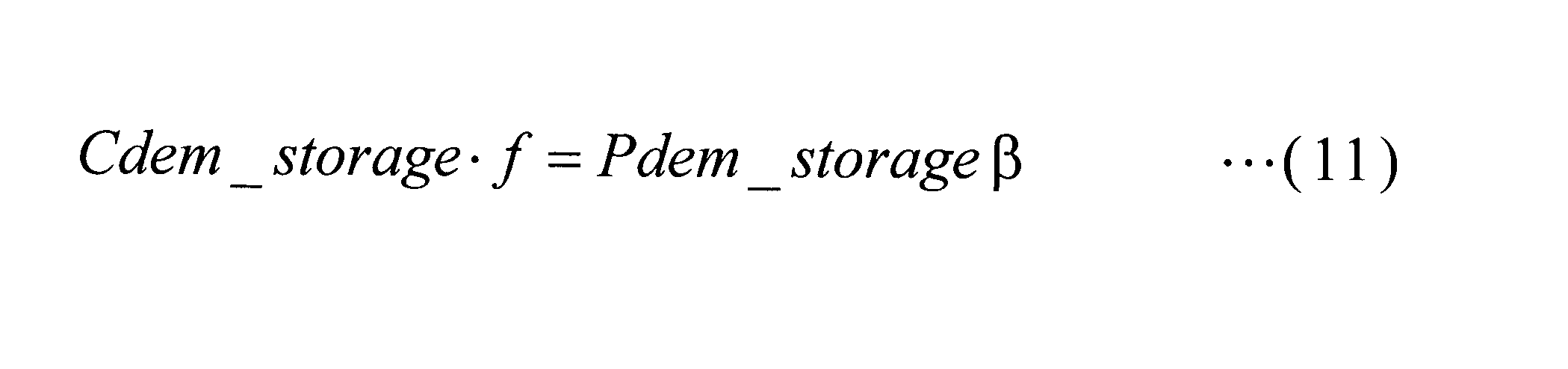
- the charging mode control unit 78 uses the value of the charging signal Pdem_storage ⁇ as an output command value Cdem_storage ⁇ f as shown in the equation (11). Output to.
- the value of the battery condition Bat_space is set as the output command value Cdem_storage ⁇ f as shown in the equation (12). Output to 58.
- the charging mode control unit 78 outputs to the wind turbine controller 52 an output command value Pdem_WTG that gives an output restriction to the wind turbine generator 10 so that the output supplied to the power system does not exceed the system required output Pgrid_lim.
- the wind turbine controller 52 receives the output command value Pdem_WTG, the wind turbine controller 52 performs control for output limitation on the wind turbine generator 10.
- the output restriction is, for example, controlling (deloading operation) so that the pitch angle of the blades 20 becomes closer to the feather side.
- the master controller 56 is a case where the noise suppression operation is not performed, and even when the output of the wind turbine generator 10 exceeds the grid required output Pgrid_lim, the master controller 56 of the wind turbine generator 10 depends on the value of the battery condition Bat_space.
- the power storage device 54 is charged with the difference between the output and the system required output Pgrid_lim.
- charge / discharge control for the power storage device 54 when the noise suppression operation is performed on the wind power generator 10 will be described with specific numerical values raised.
- Noise suppression operation is performed on the ten wind power generation devices 10 provided in the wind power generation facility 50, and the reduced output of each wind power generation device 10 in a predetermined time is set to 0.2 MW.
- the charging signal Pdem_storage ⁇ + 2 MW is obtained when the total output of the 10 wind turbine generators 10 that are operating with noise suppression is 22 MW. 2 MW charge.
- the wind power generation facility 50 includes the wind power generation device 10 and the power storage device 54 that supply power to the power system.
- the windmill controller 52 performs the noise suppression operation for controlling the rotation speed of the blade 20 in order to suppress the noise generated by the rotation of the blade 20 with respect to the wind power generator 10, and is obtained when the normal operation is performed.
- a reduced output that is an output difference between the normal output and the noise suppression output obtained when the noise suppression operation is performed is calculated.
- master controller 56 issues a command to power storage device controller 58 to cause power storage device 54 to charge and discharge based on the reduced output, the noise suppression output, and the system request output from the power system. Therefore, the wind power generation facility 50 can perform power control so as to satisfy the requirements of the power system while the wind power generation apparatus 10 is operating while suppressing the generation of noise.
- the wind power generation facility 50 discharges electric power corresponding to the reduced output from the power storage device 54 to the electric power system when the sum of the noise suppression output and the reduced output is equal to or less than the system required output.
- the wind power generation facility 50 when the sum of the noise suppression output and the reduced output exceeds the system required output and the system required output exceeds the noise suppression output, The electric power according to the difference is discharged from the power storage device 54 to the electric power system.
- the wind power generation facility 50 when the noise suppression output exceeds the system required output, the power corresponding to the difference between the noise suppression output and the system required output, that is, the surplus generated power 54 is charged.
- the windmill controller 52 causes the wind power generator 10 to output excessively more than the normal operation
- the power storage device controller 58 causes the wind power generator 10 to perform an overpower operation.
- the power storage device 54 may be charged with electric power according to the difference between the normal operation output and the overpower operation output.
- the overpower operation includes a time zone when the noise regulation is canceled, a case where the noise regulation is performed for a short time (for example, several minutes), and the like.
- the rotation speed of the blade 20 is increased as compared with the normal operation by setting the pitch angle of the blade 20 to the fine side.
- the frequency of the power system rapidly decreases, and the power storage device recovers the decreased frequency. It is possible to cope with the case where discharge from 54 is required.
- the wind power generation facility 10 has an effect of noise on the noise regulation area when the discharge time of the power storage device 54 is longer than a predetermined time (for example, several tens of minutes or more) by the noise suppression operation of the plurality of wind power generation devices 10.
- the noise suppression operation for the relatively small wind power generator 10 may be canceled and the normal operation may be performed.
- the wind power generation apparatus 10 that has a relatively small noise influence on the noise regulation area may be a wind power generation apparatus 10 that is far from the boundary with the noise regulation area, or a noise regulation area according to the wind direction.
- This is a wind turbine generator 10 that is relatively less affected by noise.
- the predetermined time is a period during which a decrease in the output of the wind turbine generator 10 in which noise suppression operation is performed is assumed, and from the subsequent wind speed prediction predicted from the wind conditions up to that time, the predetermined time or more It is determined whether or not.
- the predetermined time is defined as an elapsed time in which the charge amount of the power storage device 54 is expected to be equal to or less than a predetermined power due to the discharge of the power storage device 54, and the remaining capacity of the power charged in the power storage device 54 Depending on, it may be changed as appropriate.
- the wind power generation facility 10 can suppress the discharge amount of the power storage device 54, and in addition to the case where the noise suppression operation is performed, the frequency of the power system is drastically decreased, and the decreased frequency is recovered. It is possible to cope with a case where discharge from the power storage device 54 is required.
- wind power generation equipment 50 demonstrated the form provided with two or more wind power generation apparatuses 10 in the said embodiment, this embodiment is not limited to this,
- the wind power generation equipment 50 is 1 in the wind power generation apparatus 10. It is good also as a form provided with only one.
- the power storage device 54 may be provided for each wind turbine generator 10.
- a master controller 56 and a power storage device controller 58 are provided for each combination of the wind power generator 10 and the power storage device 54, and SCADA (Supervisory Control And Data Acquisition) 90 receives the system request output Pgrid_lim, and SCADA 90 The system request output Pgrid_lim is transmitted to each master controller 56.
- SCADA Supervisory Control And Data Acquisition
Landscapes
- Engineering & Computer Science (AREA)
- Life Sciences & Earth Sciences (AREA)
- Sustainable Development (AREA)
- Sustainable Energy (AREA)
- Chemical & Material Sciences (AREA)
- Combustion & Propulsion (AREA)
- Mechanical Engineering (AREA)
- General Engineering & Computer Science (AREA)
- Power Engineering (AREA)
- Environmental & Geological Engineering (AREA)
- Wind Motors (AREA)
- Control Of Eletrric Generators (AREA)
Abstract
Description
騒音を抑制するための方法の一例としては、翼の先端の速度(チップスピード)を低下させることが考えられ、チップスピードを低下させるためには、翼の回転数を低下させる必要がある。
そのため、騒音を抑制するために、翼の回転数を低下させる騒音抑制運転が行われる場合がある。
図7(A)に示される風速と翼の回転数との関係を示すグラフは、ピッチ角がフェザー側となるように制御することによって、翼の回転数の上昇を抑制させる場合の一例である。
図7(A)の線A(実線)は、風速が8.5m/sとなった場合に翼の回転数が15rpmで一定となるように、翼のピッチ角を制御している通常運転の場合の例を示している。しかし、この場合では、騒音が発生するので、線B(破線)に示される騒音抑制運転では、騒音が例えば105dBとなるように、風速が約7.5m/s以上でピッチ角を通常運転よりもフェザー側に制御している。これに伴い、約7.5m/sから14m/sにおける翼の回転数は、通常運転よりも低下し、風速が14m/sとなった場合に15rpmに達する。
従って、本発明は、蓄電装置に余剰電力を余すことなく蓄電することができる。
従って、本発明は、蓄電装置に充電されている電力の減少を抑制することができる。
図1は、本実施形態に係る風力発電装置10の外観図である。
図1に示す風力発電装置10は、基礎12上に立設される支柱14と、支柱14の上端に設置されるナセル16と、略水平な軸線周りに回転可能にしてナセル16に設けられるロータヘッド18とを有している。
風力発電設備50は、複数(n台、以下、nを風力発電装置10を識別するための番号とする。)の風力発電装置10、風力発電装置10毎に設けられ、風力発電装置10を制御するための風車コントローラ52、蓄電装置54、風力発電装置10及び蓄電装置54の制御を司るマスターコントローラ56、蓄電装置54を制御するための蓄電装置コントローラ58を備えている。
しかし、騒音抑制運転では、図3(B)に示されるように、線A(実線)に示される通常運転を行う場合と比較して、線B(破線)に示される騒音抑制運転の方が、風速が高い場合に風のエネルギーの一部を逃がすこととなるので、風速に対する出力は低くなる。
マスターコントローラ56は、要求出力算出部70、充放電制御判定部72、第1放電モード制御部74、第2放電モード制御部76、及び充電モード制御部78を備える。











風車コントローラ52は、上記出力指令値Pdem_WTGを受信すると、出力制限のための制御を風力発電装置10に対して行う。なお、出力制限は、例えば、翼20のピッチ角をよりフェザー側となるように制御(デロード運転)することである。
従って、風力発電設備50は、風力発電装置10に対して騒音の発生を抑制した運転を行っている間、電力系統の要求を満たすように電力制御ができる。
上記所定時間は、騒音抑制運転が行われている風力発電装置10の出力の低下が想定される期間のことであり、それまでの風況から予測されるその後の風速予測から、上記所定時間以上となるか否かが判定される。
また、上記所定時間は、蓄電装置54の放電によって、蓄電装置54の充電量が予め定められた電力以下となると予想される経過時間と規定し、蓄電装置54に充電されている電力の残容量に応じて、適宜変更されてもよい。
この形態の場合、風力発電装置10と蓄電装置54との組み合わせ毎に、マスターコントローラ56及び蓄電装置コントローラ58が設けられ、SCADA(Supervisory Control And Data Acquisition)90が系統要求出力Pgrid_limを受信し、SCADA90から各マスターコントローラ56へ系統要求出力Pgrid_limが送信される。
20 翼
50 風力発電設備
52 風車コントローラ
54 蓄電装置
56 マスターコントローラ
58 蓄電装置コントローラ
Claims (6)
- 電力系統へ電力を供給する風力発電装置、及び風力発電装置で生成された電力又は前記電力系統から供給された電力を充電し、放電によって前記電力系統へ電力を供給する蓄電装置を備えた風力発電設備であって、
前記風力発電装置に対して、翼の回転によって発生する騒音を抑制するために翼の回転数を制御する騒音抑制運転を行う風車制御部と、
前記騒音抑制運転を行う場合に得られる出力、及び前記電力系統からの要求出力に基づいて、前記蓄電装置を充放電させる蓄電装置制御部と、
を備えた風力発電設備。 - 前記蓄電装置制御部は、前記出力が前記要求出力以下の場合に、電力を前記蓄電装置から放電させる請求項1記載の風力発電設備。
- 前記蓄電装置制御部は、前記出力が前記要求出力を超える場合に、前記出力と前記要求出力との差に応じた電力を前記蓄電装置に充電させる請求項1に記載の風力発電設備。
- 前記風車制御部は、前記騒音抑制運転が行われない場合に、前記風力発電装置を、前記通常運転よりも過大に出力させる過出力運転し、
前記蓄電装置制御部は、前記風力発電装置が前記過出力運転されている場合に、前記通常運転の出力と前記過出力運転の出力との差に応じた電力を前記蓄電装置へ充電させる請求項1記載の風力発電設備。 - 複数の前記風力発電装置が、騒音の大きさが所定値以下となるよう騒音規制されている地域に隣接して設置されており、
前記風車制御部は、前記騒音抑制運転によって前記蓄電装置の放電時間が所定時間以上となる場合、前記地域に与える騒音の影響が相対的に小さい前記風力発電装置の前記騒音抑制運転を解除する請求項1記載の風力発電設備。 - 電力系統へ電力を供給する風力発電装置、及び風力発電装置で生成された電力又は前記電力系統から供給された電力を充電し、放電によって前記電力系統へ電力を供給する蓄電装置を備えた風力発電設備の制御方法であって、
前記風力発電装置に対して、翼の回転によって発生する騒音を抑制するために翼の回転数を制御する騒音抑制運転を行う第1工程と、
前記騒音抑制運転を行う場合に得られる出力、及び前記電力系統からの要求出力に基づいて、前記蓄電装置を充放電させる第2工程と、
を含む風力発電設備の制御方法。
Priority Applications (8)
| Application Number | Priority Date | Filing Date | Title |
|---|---|---|---|
| KR1020117010222A KR20120132300A (ko) | 2011-02-10 | 2011-02-10 | 풍력 발전 설비 및 풍력 발전 설비의 제어 방법 |
| CA2738519A CA2738519A1 (en) | 2011-02-10 | 2011-02-10 | Wind power plant and wind-power-plant control method |
| PCT/JP2011/052885 WO2012108033A1 (ja) | 2011-02-10 | 2011-02-10 | 風力発電設備及び風力発電設備の制御方法 |
| BRPI1100019A BRPI1100019A2 (pt) | 2011-02-10 | 2011-02-10 | instalação de energia eólica, e , método de controle de instalação de energia eólica |
| AU2011201995A AU2011201995A1 (en) | 2011-02-10 | 2011-02-10 | Wind power plant and wind-power-plant control method |
| JP2011517541A JP5579176B2 (ja) | 2011-02-10 | 2011-02-10 | 風力発電設備及び風力発電設備の制御方法 |
| CN201180000349XA CN102770663A (zh) | 2011-02-10 | 2011-02-10 | 风力发电设备和风力发电设备的控制方法 |
| US13/091,636 US8338978B2 (en) | 2011-02-10 | 2011-04-21 | Wind turbine generator having electrical storage device and acoustic noise suppression method thereof |
Applications Claiming Priority (1)
| Application Number | Priority Date | Filing Date | Title |
|---|---|---|---|
| PCT/JP2011/052885 WO2012108033A1 (ja) | 2011-02-10 | 2011-02-10 | 風力発電設備及び風力発電設備の制御方法 |
Related Child Applications (1)
| Application Number | Title | Priority Date | Filing Date |
|---|---|---|---|
| US13/091,636 Continuation US8338978B2 (en) | 2011-02-10 | 2011-04-21 | Wind turbine generator having electrical storage device and acoustic noise suppression method thereof |
Publications (1)
| Publication Number | Publication Date |
|---|---|
| WO2012108033A1 true WO2012108033A1 (ja) | 2012-08-16 |
Family
ID=44646615
Family Applications (1)
| Application Number | Title | Priority Date | Filing Date |
|---|---|---|---|
| PCT/JP2011/052885 Ceased WO2012108033A1 (ja) | 2011-02-10 | 2011-02-10 | 風力発電設備及び風力発電設備の制御方法 |
Country Status (8)
| Country | Link |
|---|---|
| US (1) | US8338978B2 (ja) |
| JP (1) | JP5579176B2 (ja) |
| KR (1) | KR20120132300A (ja) |
| CN (1) | CN102770663A (ja) |
| AU (1) | AU2011201995A1 (ja) |
| BR (1) | BRPI1100019A2 (ja) |
| CA (1) | CA2738519A1 (ja) |
| WO (1) | WO2012108033A1 (ja) |
Cited By (1)
| Publication number | Priority date | Publication date | Assignee | Title |
|---|---|---|---|---|
| JP2019513943A (ja) * | 2016-04-11 | 2019-05-30 | ヴォッベン プロパティーズ ゲーエムベーハーWobben Properties Gmbh | 風力発電装置の運転方法 |
Families Citing this family (14)
| Publication number | Priority date | Publication date | Assignee | Title |
|---|---|---|---|---|
| DE102007021632A1 (de) * | 2007-05-09 | 2008-11-20 | Ssb-Antriebstechnik Gmbh & Co. Kg | Elektrischer Antrieb |
| JP4551921B2 (ja) * | 2007-09-27 | 2010-09-29 | 株式会社日立エンジニアリング・アンド・サービス | 蓄電システム併設型風力発電システム |
| WO2012120595A1 (ja) * | 2011-03-04 | 2012-09-13 | 三菱重工業株式会社 | 風力発電システムおよび風力発電装置 |
| DK2762722T3 (en) * | 2011-09-29 | 2017-03-27 | Gen Electric | METHODS AND SYSTEM FOR OPERATING A WINDHOLDER CONNECTED TO A POWER |
| US8736094B2 (en) * | 2012-01-20 | 2014-05-27 | Mitsubishi Heavy Industries, Ltd. | Wind-turbine-generator control system, wind turbine generator, wind farm, and wind-turbine-generator control method |
| US10169832B2 (en) * | 2013-05-08 | 2019-01-01 | Instant Access Networks, Llc | Method and instrumentation for sustainable energy load flow management system performing as resilient adaptive microgrid system |
| CA2899364C (en) * | 2013-01-26 | 2019-09-24 | Equipements Wind Will Inc. | Wind turbine system |
| US9995277B2 (en) | 2014-07-31 | 2018-06-12 | General Electric Company | System and method for controlling the operation of wind turbines |
| US20160265511A1 (en) * | 2015-03-12 | 2016-09-15 | General Electric Company | System and method for reducing fan noise during noise reduced operation of a wind turbine |
| US10024304B2 (en) | 2015-05-21 | 2018-07-17 | General Electric Company | System and methods for controlling noise propagation of wind turbines |
| CN108028546B (zh) * | 2015-09-01 | 2020-09-08 | 东芝三菱电机产业系统株式会社 | 发电设备以及发电控制装置 |
| US11411429B2 (en) * | 2016-03-29 | 2022-08-09 | Kyocera Corporation | Management system, management method, power conversion device, and management device |
| JP7833492B2 (ja) * | 2024-03-21 | 2026-03-19 | 日鉄エンジニアリング株式会社 | 洋上風車システム |
| US12368195B1 (en) | 2025-03-25 | 2025-07-22 | BrightNight Power LLC | Noise-constrained energy storage system dispatch |
Citations (4)
| Publication number | Priority date | Publication date | Assignee | Title |
|---|---|---|---|---|
| JP2002171669A (ja) * | 2000-12-01 | 2002-06-14 | Nissin Electric Co Ltd | 系統安定化システム及びその制御方法 |
| JP2005036749A (ja) * | 2003-07-17 | 2005-02-10 | Fuji Heavy Ind Ltd | 水平軸風車及びその制御方法 |
| JP2008182859A (ja) * | 2007-01-26 | 2008-08-07 | Hitachi Industrial Equipment Systems Co Ltd | 風力発電装置と蓄電装置のハイブリッドシステム,風力発電システム,電力制御装置 |
| WO2010073310A1 (ja) * | 2008-12-22 | 2010-07-01 | 日本風力開発株式会社 | 蓄電池併設型自然エネルギー発電システムの電力管理制御システム |
Family Cites Families (14)
| Publication number | Priority date | Publication date | Assignee | Title |
|---|---|---|---|---|
| US3637186A (en) * | 1969-10-16 | 1972-01-25 | Avnet Inc | Detent swivel for truck mirrors and the like |
| FR2255041B1 (ja) * | 1973-12-24 | 1977-06-10 | Hirdes Rudigar | |
| JP3637186B2 (ja) | 1997-09-11 | 2005-04-13 | 三菱重工業株式会社 | 風力発電装置の電力制御方法 |
| EP1389682B1 (de) | 1999-06-10 | 2005-10-19 | Aloys Wobben | Verfahren zum Betreiben eines Windparks |
| JP2002349413A (ja) * | 2001-05-24 | 2002-12-04 | Mitsubishi Electric Corp | 風力発電システム |
| NZ565921A (en) * | 2005-07-15 | 2011-05-27 | Southwest Windpower Inc | Wind turbine and method of manufacture |
| JP2007056686A (ja) | 2005-08-22 | 2007-03-08 | Univ Of Ryukyus | 風速予測に基づく風力発電機の数時間先発電電力予測装置 |
| US7988414B2 (en) * | 2008-10-20 | 2011-08-02 | General Electric Company | Method and system for operating a wind turbine generator |
| JP5107271B2 (ja) | 2009-01-06 | 2012-12-26 | 三菱重工業株式会社 | 風力発電装置及びそのブレードピッチ角制御方法並びにプログラム |
| US20100135798A1 (en) * | 2009-02-10 | 2010-06-03 | General Electric Company | Wind turbine noise controls |
| US7896613B2 (en) * | 2009-06-03 | 2011-03-01 | General Electric Company | System and method for wind turbine noise control and damage detection |
| US7945350B2 (en) * | 2009-07-07 | 2011-05-17 | General Electric Company | Wind turbine acoustic emission control system and method |
| US7902689B2 (en) | 2009-07-07 | 2011-03-08 | General Electric Company | Method and system for noise controlled operation of a wind turbine |
| JP5031119B1 (ja) * | 2011-08-10 | 2012-09-19 | 三菱重工業株式会社 | 風力発電所の制御装置及び風力発電所の制御方法 |
-
2011
- 2011-02-10 CN CN201180000349XA patent/CN102770663A/zh active Pending
- 2011-02-10 KR KR1020117010222A patent/KR20120132300A/ko not_active Ceased
- 2011-02-10 AU AU2011201995A patent/AU2011201995A1/en not_active Abandoned
- 2011-02-10 WO PCT/JP2011/052885 patent/WO2012108033A1/ja not_active Ceased
- 2011-02-10 BR BRPI1100019A patent/BRPI1100019A2/pt not_active IP Right Cessation
- 2011-02-10 CA CA2738519A patent/CA2738519A1/en not_active Abandoned
- 2011-02-10 JP JP2011517541A patent/JP5579176B2/ja not_active Expired - Fee Related
- 2011-04-21 US US13/091,636 patent/US8338978B2/en not_active Expired - Fee Related
Patent Citations (4)
| Publication number | Priority date | Publication date | Assignee | Title |
|---|---|---|---|---|
| JP2002171669A (ja) * | 2000-12-01 | 2002-06-14 | Nissin Electric Co Ltd | 系統安定化システム及びその制御方法 |
| JP2005036749A (ja) * | 2003-07-17 | 2005-02-10 | Fuji Heavy Ind Ltd | 水平軸風車及びその制御方法 |
| JP2008182859A (ja) * | 2007-01-26 | 2008-08-07 | Hitachi Industrial Equipment Systems Co Ltd | 風力発電装置と蓄電装置のハイブリッドシステム,風力発電システム,電力制御装置 |
| WO2010073310A1 (ja) * | 2008-12-22 | 2010-07-01 | 日本風力開発株式会社 | 蓄電池併設型自然エネルギー発電システムの電力管理制御システム |
Cited By (2)
| Publication number | Priority date | Publication date | Assignee | Title |
|---|---|---|---|---|
| JP2019513943A (ja) * | 2016-04-11 | 2019-05-30 | ヴォッベン プロパティーズ ゲーエムベーハーWobben Properties Gmbh | 風力発電装置の運転方法 |
| US10683843B2 (en) | 2016-04-11 | 2020-06-16 | Wobben Properties Gmbh | Method for operating a wind turbine |
Also Published As
| Publication number | Publication date |
|---|---|
| CA2738519A1 (en) | 2012-08-10 |
| KR20120132300A (ko) | 2012-12-05 |
| US20110227343A1 (en) | 2011-09-22 |
| BRPI1100019A2 (pt) | 2019-09-24 |
| JP5579176B2 (ja) | 2014-08-27 |
| US8338978B2 (en) | 2012-12-25 |
| JPWO2012108033A1 (ja) | 2014-07-03 |
| CN102770663A (zh) | 2012-11-07 |
| AU2011201995A1 (en) | 2012-08-30 |
Similar Documents
| Publication | Publication Date | Title |
|---|---|---|
| JP5579176B2 (ja) | 風力発電設備及び風力発電設備の制御方法 | |
| EP2649309B1 (en) | Dynamic adjustment of power plant output based on electrical grid characteristics | |
| EP2307715B2 (en) | Power curtailment of wind turbines | |
| CA2724601C (en) | Wind turbine generator and output power control method | |
| US9835136B2 (en) | System and method for extending the operating life of a wind turbine gear train based on energy storage | |
| US8324751B2 (en) | Wind turbine generator system and wind turbine generator | |
| CN102518555B (zh) | 一种兆瓦级风力机组及其控制方法、控制系统 | |
| CN103052793B (zh) | 风车的输出控制装置及输出控制方法 | |
| KR101141090B1 (ko) | 풍력 발전 장치의 제어 장치, 윈드팜, 및 풍력 발전 장치의 제어 방법 | |
| JPWO2013073017A1 (ja) | 風力発電システム及びその制御方法 | |
| JP5031119B1 (ja) | 風力発電所の制御装置及び風力発電所の制御方法 | |
| CN112997001A (zh) | 使用风力涡轮机为储能系统充电的方法 | |
| EP2963285B1 (en) | A method for controlling a wind turbine including reversing an energy flow through a generator | |
| Liu et al. | Power smooth control for DFIG under extreme operating gust |
Legal Events
| Date | Code | Title | Description |
|---|---|---|---|
| WWE | Wipo information: entry into national phase |
Ref document number: 201180000349.X Country of ref document: CN |
|
| WWE | Wipo information: entry into national phase |
Ref document number: 2011201995 Country of ref document: AU |
|
| ENP | Entry into the national phase |
Ref document number: 2738519 Country of ref document: CA Kind code of ref document: A |
|
| WWE | Wipo information: entry into national phase |
Ref document number: 2011517541 Country of ref document: JP |
|
| WWE | Wipo information: entry into national phase |
Ref document number: 3054/DELNP/2011 Country of ref document: IN Ref document number: 2011714672 Country of ref document: EP |
|
| ENP | Entry into the national phase |
Ref document number: 20117010222 Country of ref document: KR Kind code of ref document: A |
|
| 121 | Ep: the epo has been informed by wipo that ep was designated in this application |
Ref document number: 11714672 Country of ref document: EP Kind code of ref document: A1 |
|
| NENP | Non-entry into the national phase |
Ref country code: DE |