WO2012107981A1 - Motor rotor, and fan driving motor provided therewith - Google Patents
Motor rotor, and fan driving motor provided therewith Download PDFInfo
- Publication number
- WO2012107981A1 WO2012107981A1 PCT/JP2011/006827 JP2011006827W WO2012107981A1 WO 2012107981 A1 WO2012107981 A1 WO 2012107981A1 JP 2011006827 W JP2011006827 W JP 2011006827W WO 2012107981 A1 WO2012107981 A1 WO 2012107981A1
- Authority
- WO
- WIPO (PCT)
- Prior art keywords
- wall surface
- rotor
- motor
- flux barrier
- permanent magnet
- Prior art date
Links
Images


Classifications
-
- H—ELECTRICITY
- H02—GENERATION; CONVERSION OR DISTRIBUTION OF ELECTRIC POWER
- H02K—DYNAMO-ELECTRIC MACHINES
- H02K1/00—Details of the magnetic circuit
- H02K1/06—Details of the magnetic circuit characterised by the shape, form or construction
- H02K1/22—Rotating parts of the magnetic circuit
- H02K1/27—Rotor cores with permanent magnets
- H02K1/2706—Inner rotors
- H02K1/272—Inner rotors the magnetisation axis of the magnets being perpendicular to the rotor axis
- H02K1/274—Inner rotors the magnetisation axis of the magnets being perpendicular to the rotor axis the rotor consisting of two or more circumferentially positioned magnets
- H02K1/2753—Inner rotors the magnetisation axis of the magnets being perpendicular to the rotor axis the rotor consisting of two or more circumferentially positioned magnets the rotor consisting of magnets or groups of magnets arranged with alternating polarity
- H02K1/276—Magnets embedded in the magnetic core, e.g. interior permanent magnets [IPM]
-
- H—ELECTRICITY
- H02—GENERATION; CONVERSION OR DISTRIBUTION OF ELECTRIC POWER
- H02K—DYNAMO-ELECTRIC MACHINES
- H02K1/00—Details of the magnetic circuit
- H02K1/06—Details of the magnetic circuit characterised by the shape, form or construction
- H02K1/22—Rotating parts of the magnetic circuit
- H02K1/27—Rotor cores with permanent magnets
- H02K1/2706—Inner rotors
Definitions
- the present invention relates to a rotor of a motor and a fan driving motor including the same, and more particularly to a rotor of a brushless motor intended for high-speed rotation and a fan driving motor including the same.
- a hole is provided in order to increase the output and efficiency of the motor.
- a part of the inner wall of the rotor is formed so as not to come into contact with the permanent magnet, and the rotor part between the inner wall of a part of the hole and the outer circumferential edge of the rotor on the radially outer side of the inner wall is formed from the permanent magnet.
- the conventional configuration including the above-mentioned Patent Documents 1 and 2 has a problem that the flux barrier portion is broken when it is rotated at a higher speed (for example, 100,000 revolutions / minute (rpm) or more).
- a higher speed for example, 100,000 revolutions / minute (rpm) or more.
- the flux barrier part is thickened to ensure strength, or by reducing the permanent magnet, the centrifugal force applied to the permanent magnet is reduced and acts on the outer rotor part. It is conceivable to reduce the force to perform.
- both of these methods lead to low output and low efficiency of the motor, so that high speed rotation cannot be realized while miniaturizing the motor.
- the fan driving motor is required to be reduced in size and output in order to reduce the size and increase the output of the cleaner.
- Conventional fan drive motors generally have a normal rotational speed of about 20,000 rpm or less, and even those that rotate at high speed are limited to about 40,000 to 50,000 rpm at the maximum. A fan driving motor having a normal rotational speed has not been realized.
- the present invention solves such a conventional problem, and provides a rotor for a motor capable of realizing high-speed rotation by effectively dispersing stress on the flux barrier portion while reducing leakage magnetic flux, and the same.
- An object of the present invention is to provide a fan driving motor provided.
- the rotor of the motor according to the present invention is a rotor of a motor in which a permanent magnet is inserted into a hole provided inside, and the hole is on a virtual plane including the center of the rotation shaft of the motor.
- a planar first inner wall surface that is perpendicular and formed to be bisected by the virtual plane, and extends radially outward from the first inner wall surface in parallel with the first inner wall surface.
- the second inner wall surface has a length in a cross-sectional view perpendicular to the rotation axis.
- the side wall surface is longer than the first inner wall surface, and the side wall surface extends from both ends of the second inner wall surface to the outside in the extending direction of the inner wall surface and from the second inner wall surface in a cross-sectional view perpendicular to the rotation axis.
- a flux burr extending away from the outer peripheral edge of the rotor toward the first inner wall surface
- four or more holes are formed at equal intervals in the circumferential direction of the rotor, and the permanent magnets are inserted radially into the holes in the radially outer side.
- Two or more facing polarities are arranged in the circumferential direction of the rotor so as to be the same.
- the permanent magnet since the length of the second inner wall surface in the cross-sectional view perpendicular to the rotation axis is longer than the first inner wall surface on the inner side, the permanent magnet is inserted by the centrifugal force of the permanent magnet inserted into the hole. The stress acting on the rotor portion outside the magnet is prevented from concentrating on the boundary between the second inner wall surface and the side wall surface.
- the flux barrier wall surface that is separated from the outer peripheral edge of the rotor as it goes from the second inner wall surface to the first inner wall surface is formed on the side wall surface, it acts on the permanent magnet and the outer rotor portion. Is prevented from concentrating on the boundary between the second inner wall surface and the side wall surface.
- a rotor capable of withstanding high-speed rotation can be configured without increasing the thickness of the flux barrier portion. Therefore, high-speed rotation can be realized while reducing the leakage magnetic flux.
- the polarity of the permanent magnet toward the outer side in the radial direction is Two or more of them are arranged in the circumferential direction so as to be the same. Therefore, the size of the permanent magnet per pole can be reduced. Therefore, since the stress due to the mass of the permanent magnet can be reduced, high-speed rotation can be realized while forming the flux barrier portion relatively thin. Further, when permanent magnets having the same size are used, the amount of magnetic flux increases, so that the rotor can be rotated at a higher speed even if the flux barrier portion has the same thickness. Furthermore, by reducing the number of poles without reducing the magnetic flux of the permanent magnet, the switching frequency for changing the direction of the current flowing through the stator coil can be lowered, so that the motor can be rotated at a higher speed. It can be easily realized.
- the flux barrier wall surface has an arc shape in a cross-sectional view perpendicular to the rotation axis, and the arc has a center of a virtual circle including the arc and the first inner wall surface in the virtual plane and the rotation.
- the virtual circle may be located between the center of the shaft and the inner side of the outer periphery of the rotor.
- the side wall surface includes a positioning wall surface that is perpendicular to the second inner wall surface in the longitudinal direction from both ends of the second inner wall surface in a cross-sectional view perpendicular to the rotation axis, the positioning wall surface, and the flux barrier.
- You may have the connection wall surface which connects a wall surface. Thereby, position shift of a permanent magnet can be prevented, forming a flux barrier wall surface effectively.
- the hole may have a groove formed radially inward from the first inner wall surface between the side wall surface and both ends of the first inner wall surface.
- the permanent magnet inserted into the hole may be formed using a rare earth element.
- a high-magnetism permanent magnet formed using a rare earth element it is possible to increase the output while reducing the size of the rotor.
- the fan driving motor according to the present invention has the rotor of the motor configured as described above.
- the motor rotor capable of realizing high-speed rotation while reducing the leakage magnetic flux is applied to the fan driving motor, whereby the motor can be reduced in size and increased in output. .
- the present invention is configured as described above, and has an effect that high-speed rotation can be realized by effectively dispersing stress on the flux barrier portion while reducing leakage magnetic flux.
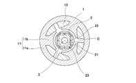
- FIG. 1 is a cross-sectional view showing a cross-sectional structure of a motor including a motor rotor according to an embodiment of the present invention.
- FIG. 2 is an enlarged view showing a cross-sectional configuration of the rotor of the motor shown in FIG.
- FIG. 3 is an enlarged sectional view showing a sectional configuration of the rotor of the motor shown in FIG.
- FIG. 4 is an enlarged view showing a cross-sectional configuration of the rotor of the motor in a modification of the embodiment of the present invention.
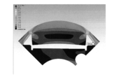
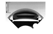
- FIG. 5 is a stress distribution diagram of the rotor in the embodiment of the present invention.
- FIG. 6 is a graph showing the outer diameter value of the rotational speed with respect to the rotational speed when the rotor in the embodiment of the present invention is rotated.
- FIG. 7 is an enlarged cross-sectional view showing a cross-sectional configuration of a rotor in a comparative example for the present invention.
- FIG. 8 is a stress distribution diagram of a rotor in a comparative example for the present invention.
- FIG. 1 is a cross-sectional view showing a cross-sectional structure of a motor including a motor rotor according to an embodiment of the present invention.
- a brushless motor hereinafter simply referred to as a motor
- a motor in this embodiment includes a cylindrical stator 1 attached to an inner wall surface of an outer frame (not shown), and an inner side of the stator 1. It has a cylindrical rotor 2 that is held so as to be rotatable relative to the stator 1.
- a shaft hole 3 is provided at the center of the rotor 2, and the rotor 2 and the shaft are fixed in a state where a shaft (not shown) is inserted through the shaft hole 3.
- the stator 1 has a cylindrical portion 11a formed in a cylindrical shape, and a plurality of (three in the present embodiment) tooth portions 11b extending radially inward from the inner wall surface of the cylindrical portion 11a. It has the core iron core 11 and the coil (coil) 12 wound by each of the teeth (teeth) part 11b.
- the rotor 2 has a cylindrical rotor core 21 and a plurality of rotor cores 21 (four in the present embodiment) along the circumferential direction of the rotor 2 (circumferential direction of the rotation axis C) inside the rotor core 21. And a permanent magnet 22 embedded in the formed hole 23. In the present embodiment, the four holes 23 are formed at equal intervals in the circumferential direction of the rotor 2.
- the permanent magnet 22 is formed in a plate shape.
- the corners of the permanent magnet 22 may be chamfered or rounded. Thereby, the crack at the time of manufacture of permanent magnet 22 and a chip can be prevented.
- the permanent magnet 22 is a rare earth magnet formed using a rare earth element such as Neodymium. By using the high-magnetism permanent magnet 22 formed using a rare earth element, the rotor 2 can be reduced in size and output can be increased.
- the permanent magnets 22 are arranged so that the two polarities directed radially outward are the same in the circumferential direction of the rotor 2 in the state of being inserted into the holes 23. . That is, the permanent magnets 22 are disposed so that the polarities of the permanent magnets 22 facing each other across the rotation axis C are different from each other in the state of being inserted into the holes 23 (see FIG. 1, only the polarities on the outer side in the radial direction of the permanent magnet 22 are displayed on the permanent magnet 22).
- a two-pole rotor 2 using four permanent magnets 22 is configured.
- the size of the permanent magnet 22 per pole can be reduced. Therefore, since the stress due to the mass of the permanent magnet 22 can be reduced, high-speed rotation can be realized while forming the flux barrier portion 21a relatively thin. Further, when the same size permanent magnet 22 is used, the amount of magnetic flux increases, so that the rotor 2 can be rotated at higher speed even if the flux barrier portion 21a has the same thickness.
- the permanent magnets 22 are arranged so that the two polarities facing radially outward are the same in the circumferential direction of the rotor 2 with the permanent magnets 22 inserted into the holes 23. ing. Thereby, the number of poles can be reduced without reducing the magnetic flux of the permanent magnet 22, and the switching frequency for changing the direction of the current flowing through the coil 12 of the stator 1 can be lowered. Therefore, high-speed rotation of the motor can be realized more easily.
- the number of permanent magnets to four, an effective number of rotations can be obtained with the minimum number of permanent magnets 22 and a high-performance motor can be configured while preventing an increase in cost.
- the rotor core 21 and the permanent magnet 22 may be fixed with a suitable adhesive.
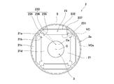
- FIG. 2 is an enlarged view showing a sectional configuration of the rotor of the motor shown in FIG.
- the hole 23 formed in the rotor 2 is perpendicular to a virtual plane (a line segment in the cross-sectional view shown in FIG. 2) S including the center of the rotation axis C of the motor, and A planar first inner wall surface 231 formed to be bisected by the virtual plane S, and a first inner wall surface 231 extending radially outward from the first inner wall surface 231 and parallel to the first inner wall surface 231.
- the second inner wall surface 232 has a length in a cross-sectional view perpendicular to the rotation axis C (that is, a length in the cross-sectional view shown in FIG. 2) longer than the first inner wall surface 231.
- the side wall surface 233 extends outwardly from the both ends of the second inner wall surface 232 in the cross-sectional view perpendicular to the rotation axis C (in the cross-sectional view shown in FIG. 2, the longitudinal direction) outside.
- a flux barrier wall surface 234 that extends away from the outer peripheral edge 2a of the rotor 2 as it goes from the inner wall surface 232 toward the first inner wall surface 231 is provided.
- the rotor core portion between the flux barrier wall surface 234 and the outer peripheral edge 2a constitutes the flux barrier portion 21a.
- the side wall surface 233 includes a positioning wall surface 235 perpendicular to the second inner wall surface 232 on the inner side in the longitudinal direction from both ends of the second inner wall surface 232 in a cross-sectional view perpendicular to the rotation axis C, and the positioning wall surface 235.
- a connecting wall surface 236 that connects the flux barrier wall surface 234.
- the hole 23 has a groove portion 237 formed radially inward from the first inner wall surface 231 between the side wall surface 233 and both ends of the first inner wall surface 231.
- the four holes 23 are formed in the rotor 2 in the present embodiment. More specifically, the four holes 23 are formed such that the first inner wall surface 231 and the second inner wall surface 232 of the adjacent holes 23 are perpendicular to each other. Then, the outer peripheral portion 21c radially outside the second inner wall surface 232 of the rotor core 21 and the diameter from the first inner wall surface 231 by the positioning wall surface 235 and the connecting wall surface 236 of the adjacent holes 23 together with the flux barrier portion 21a. A bridge portion 21b that connects the central portion 21d on the inner side in the direction is configured.
- a plate-like permanent magnet 22 is inserted into the hole 23 formed in this way.
- the length of the second inner wall surface 232 in a cross-sectional view perpendicular to the rotation axis C is longer than the first inner wall surface 231 on the inner side, when the plate-shaped permanent magnet 22 is inserted, The outer corners of the magnet 22 are positioned on the inner side of both ends of the second inner wall surface 232. Therefore, when the rotor 2 rotates around the rotation axis C, stress acting on the rotor portion (outer peripheral portion 21 c) outside the permanent magnet 22 due to the centrifugal force of the permanent magnet 22 inserted into the hole 23. Concentration at the boundary between the second inner wall surface 232 and the side wall surface 233 is prevented.
- the positioning wall surface 235 as described above, the permanent magnet 22 is prevented from being displaced while the flux barrier wall surface 234 is effectively formed. Further, by providing the groove 237 between the side wall surface 233 (positioning wall surface 235) and the first inner wall surface 231, the side wall surface 233 (positioning wall surface 235) and the first inner wall surface are produced during the manufacture of the rotor 2.
- the connecting portion with H.231 can be sharply processed, and the manufacturing accuracy in the connecting portion between the side wall surface 233 and the first inner wall surface 231 can be increased. For this reason, since the permanent magnet 22 is positioned in the hole 23 with high accuracy, the displacement of the permanent magnet 22 can be more effectively prevented.
- the side wall surface 233 is formed with a flux barrier wall surface 234 that moves away from the outer peripheral edge 2a of the rotor 2 toward the first inner wall surface 231 from the second inner wall surface 232.
- the stress acting on the magnet 22 and the outer peripheral portion 21c is prevented from concentrating on the boundary portion between the second inner wall surface 232 and the side wall surface 233.
- the rotor 2 that can endure high-speed rotation without increasing the thickness of the flux barrier portion 21a can be configured. . Therefore, high-speed rotation can be realized while reducing the leakage magnetic flux.
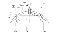
- FIG. 3 is an enlarged sectional view showing a sectional configuration of the rotor of the motor shown in FIG.
- the flux barrier wall surface 234 that defines the flux barrier portion 21 a has an arc shape in a cross-sectional view perpendicular to the rotation axis C.
- the center Ca of the virtual circle VC including the arc is located between the first inner wall surface 231 and the center of the rotation axis C in the virtual plane S, and the virtual circle VC is the rotor 2. It is located inside the outer peripheral edge 2a (included in the rotor 2).
- the virtual circle VC is centered on the center of the rotation axis C of the rotor 2 and touches the virtual concentric circle VCo of the outer peripheral edge 2a having a shorter radius than the outer peripheral edge 2a on the virtual plane S (the radius of the virtual circle VC is It becomes shorter than the radius of the virtual concentric circle VCo).
- the arc is formed so that the virtual concentric circle VCo that is in contact with the virtual circle VC on the virtual plane S has a radius smaller than the radius of the outer peripheral edge 2a with the center of the rotation axis C of the rotor 2 as the center.
- the permanent magnet 22 and the outer peripheral portion 21c located outside thereof are integrally subjected to centrifugal force.
- the mass point at which the centrifugal force is generated from the stress distribution at this time can be divided into a portion 21c1 outside the virtual circle VC obtained by extending the arc of the flux barrier wall surface 234 and a portion 21c2 inside. That is, it can be considered that the centrifugal force due to the combined mass of the permanent magnet 22 and the portion 21c2 inside the virtual circle VC of the outer peripheral portion 21c acts on the portion 21c1 outside the virtual circle VC of the outer peripheral portion 21c.
- the portion 21c1 outside the virtual circle VC of the outer peripheral portion 21c has a radial thickness that increases from the portion intersecting the virtual plane S toward the bridge portion 21b. For this reason, the stress acting on the portion 21c1 outside the virtual circle VC of the outer peripheral portion 21c against the centrifugal force caused by the combined mass of the permanent magnet 22 and the portion 21c2 inside the virtual circle VC of the outer peripheral portion 21c is As it goes from the intersecting portion toward the bridge portion 21b, it becomes weaker as a whole, and also in the direction of stress, the radial component decreases and the tangential component increases.
- a stress substantially parallel to the tangential direction of the outer peripheral edge 2a acts in the flux barrier portion 21a in the vicinity of the bridge portion 21b. Since the strength of the bridge portion 21b is weak in the radial direction and strong in the tangential direction from the shape thereof, the bridge portion 21b is not easily broken even if a stress substantially parallel to the tangential direction acts on the flux barrier portion 21a.
- the stress acting on the flux barrier portion 21a is caused to act in a direction inclined with respect to the radial direction while effectively dispersing the stress acting on the permanent magnet 22 and the outer rotor portion (the outer peripheral portion 21c). Can do. Accordingly, since the stress acting on the flux barrier portion 21a is weakened by dispersing the stress, the direction of the stress acting on the flux barrier portion 21a can be directed to the direction strong against breaking, so that the breaking on the flux barrier portion 21a is effective. Can be prevented.
- FIG. 7 is an enlarged cross-sectional view showing a cross-sectional configuration of a rotor in a comparative example for the present invention.
- the arc of the flux barrier wall surface 234r is coincident with a virtual concentric circle VCr in which the center of the virtual circle VCr including the arc coincides with the center of the rotation axis C.
- the permanent magnet 22r and the outer peripheral portion 21cr located outside thereof are integrally subjected to centrifugal force.
- the mass point at which the centrifugal force is generated from the stress distribution at this time can be divided into a portion 21c1r outside the virtual circle VCr extending the arc of the flux barrier wall surface 234r and a portion 21c2r inside. That is, it can be considered that the centrifugal force due to the combined mass of the permanent magnet 22r and the portion 21c2r inside the virtual circle VCr of the outer peripheral portion 21cr acts on the portion 21c1r outside the virtual circle VCr of the outer peripheral portion 21cr.
- the portion 21c1r outside the virtual circle VCr of the outer peripheral portion 21cr has a constant thickness in the radial direction from the portion intersecting the virtual plane S to the bridge portion 21br.
- the stress acting on the portion 21c1r outside the virtual circle VCr of the outer peripheral portion 21cr with respect to the centrifugal force due to the combined mass of the permanent magnet 22r and the portion 21c2r inside the virtual circle VCr of the outer peripheral portion 21cr is From the intersecting portion, the bridge portion 21br is applied substantially evenly in the radial direction. Accordingly, a relatively large stress acts in the radial direction also on the flux barrier portion 21ar in the vicinity of the bridge portion 21br.
- the strength of the bridge portion 21br is weak in the radial direction and strong in the tangential direction from the shape thereof, when the radial stress acts on the flux barrier portion 21ar, the thickness is reduced with respect to the outer peripheral portion 21cr as a result.
- the stress concentrates on the flux barrier portion 21ar (particularly where the corner portion of the permanent magnet contacts).
- the deformation of the bridge portion 21br due to the rotation of the rotor 2R is increased, and the bridge portion 21br is easily broken.
- the arc of the flux barrier wall surface is such that the center Ca of the virtual circle VC including the arc is located between the first inner wall surface 231 and the center of the rotation axis C in the virtual plane S.
- the virtual circle VC is located outside the outer peripheral edge 2a of the rotor 2 (the virtual concentric circle VCo is longer than the radius of the outer peripheral edge 2a), the rotor 2 , The stress concentrates on the boundary between the second inner wall surface 232 and the flux barrier wall surface.
- the arc of the flux barrier wall surface is located on the side closer to the air hole 23 where the center Ca of the virtual circle VC including the arc is opposed to the center of the rotation axis C in the virtual plane S. (When the radius of the virtual circle VC is larger than the virtual concentric circle VCo), the end of the flux barrier wall surface opposite to the boundary with the second inner wall 232 (boundary with the connecting wall) Stress is concentrated. When stress concentration occurs in the flux barrier portion, the bridge portion is easily broken.
- the direction of the stress acting on the flux barrier portion 21a whose thickness is reduced with respect to the outer peripheral portion 21c is large in the tangential direction, and in the radial direction. Since the stress itself becomes weaker as it becomes smaller, the stress is not concentrated on the flux barrier portion 21a, the deformation of the bridge portion 21b due to the rotation of the rotor 2 can be reduced, and the breakage of the bridge portion 21b is effectively prevented. Can do. Thereby, high-speed rotation of a motor is realizable, without increasing the thickness of the flux barrier part 21a and the bridge
- the leakage magnetic flux can be reduced by relatively reducing the thickness of the flux barrier portion 21a, a necessary induced voltage can be obtained even if the permanent magnet 22 is downsized (magnetic flux with respect to the size of the permanent magnet). Can increase the effective utilization rate).
- high-speed rotation can be realized while reducing the leakage magnetic flux, it is possible to reduce the size and increase the output of the motor.
- the side wall surface 233 has a structure in which the positioning wall surface 235 and the connecting wall surface 236 are formed between the flux barrier wall surface 234 and the first inner wall surface 231.
- the shape of the side wall surface 233 other than the flux barrier wall surface 234 is not particularly limited.
- FIG. 4 is an enlarged view showing a cross-sectional configuration of the rotor of the motor in a modification of the embodiment of the present invention.
- the side wall surface 233b has a planar connecting wall surface 237 that connects both ends of the first inner wall surface 231 and the corresponding flux barrier wall surface 234.
- the planar connecting wall surface 237 in the present modification is formed in a straight line in a cross-sectional view perpendicular to the rotation axis C. Even with such a shape, the permanent magnet 22 inserted into the hole 23 can be positioned.
- the shape of the portion connecting the flux barrier wall surface 234 and the first inner wall surface 231 on the side wall surface 233 is not limited to the above-described embodiment and the above-described modification examples, and various shapes can be applied.
- the rotor (Example) in which the flux barrier wall surface 234 is formed as described in the above embodiment and the flux barrier wall surface 234r are formed with a constant width of the flux barrier portion as in the comparative example shown in FIG.
- the result of carrying out strength analysis in each of the rotor (comparative example) is shown.
- a stress distribution diagram at a predetermined rotation speed here, 80,000 rpm
- the same iron plate material having the same yield stress (413 MPa) was used in both the examples and the comparative examples, and four holes were provided, and permanent magnets of the same material were inserted.
- the dimensions of the permanent magnets are the same in thickness (diameter dimension), but the width (tangential dimension) is 9.5 mm in the example, whereas it is 10 mm in the comparative example.
- the width of the flux barrier portion was 0.7 mm in both this example and this comparative example (the width of the thinnest part in this example).
- the strength analysis was performed with a 1/4 model of each rotor.
- FIG. 5 is a stress distribution diagram of the rotor in the embodiment of the present invention.
- FIG. 8 is a stress distribution diagram of the rotor in the comparative example for the present invention.
- the stress is distributed stepwise along the outer peripheral edge of the rotor core, so that the stress due to centrifugal force is higher than that in the embodiment shown in FIG. It can be seen that it is evenly applied to the outer periphery. Further, it can be seen from the outline that the comparative example shown in FIG. 8 has a larger deformation amount as a whole than the embodiment shown in FIG. In FIG. 5 and FIG. 8, the place where the stress is most applied is indicated by an arrow Smax.
- the maximum stress which is the stress value at Smax, was 257.4 MPa in the example shown in FIG. 5, whereas it was 405.3 MPa in the comparative example shown in FIG.
- the maximum stress in the rotor of the comparative example is significantly higher than the maximum stress in the rotor of the embodiment.
- the stress acts on the entire area of the flux barrier wall surface.
- the comparative example shown in FIG. 8 it is considered that stress concentrates and acts only near the arrow Smax in the flux barrier wall surface.
- FIG. 6 is a graph showing the outer diameter value of the rotational speed with respect to the rotational speed when the rotor in the embodiment of the present invention is rotated.
- the diameter between the central portions (in the virtual plane S) of the opposing permanent magnets 22 among the four permanent magnets 22 is measured at three locations (both ends and the central portion) in the rotation axis C direction.
- the diameter of a total of six places was measured and the average was taken.
- the amount of deformation corresponding to the rotational speed was estimated from the analysis data in Example 1 for the rotor shown in FIGS.
- the rotational speed reaches 100,000 rpm in all the rotors including the 0.5 mm-wide rotor with the smallest flux barrier portion 21a.
- the rotor hardly deformed.
- the width is 0.7 mm, deformation is suppressed to a level close to 120,000 rpm, and a very high rotational speed can be realized until the bridge portion 21b is broken until it finally reaches 148,000 rpm.
- the graph changes close to the example of 0.5 mm width, and only the strength of the example of 0.5 mm width is obtained although the width of the flux barrier portion is 0.7 mm. I found that there was no. From the above, it was shown that the strength of the rotor of the example according to the present invention was remarkably increased without increasing the thickness of the flux barrier portion 21a as compared with the comparative example.
- the three permanent magnets are arranged so that the polarities directed outward in the radial direction are the same in the circumferential direction of the rotor.
- the polarity of the permanent magnet toward the outer side in the radial direction is It is good also as a structure arrange
- the motor rotor of the present invention and a fan driving motor equipped with the rotor are useful for realizing high-speed rotation by effectively dispersing stress on the flux barrier portion while reducing leakage magnetic flux.
Abstract
Description
2 回転子
2a 外周縁
3 シャフト孔
11 固定子鉄心
11a 筒状部
11b ティース部
12 コイル
21 回転子鉄心
21a フラックスバリア部
21b ブリッジ部
21c 外周部
21c1 仮想円より外側の部分
21c2 仮想円より内側の部分
21d 中央部
22 永久磁石
23 空孔
231 第1の内壁面
232 第2の内壁面
233 側壁面
234 フラックスバリア壁面
235 位置決め壁面
236 連接壁面
237 溝部
C 回転軸
Ca 仮想円の中心
S 仮想平面
VC 仮想円
VCo 仮想同心円
DESCRIPTION OF
Claims (7)
- 内部に設けられた空孔内に永久磁石が挿入されるモータの回転子であって、
前記空孔は、
前記モータの回転軸の中心を含む仮想平面に垂直でありかつ当該仮想平面により二等分されるよう形成された平面状の第1の内壁面と、
当該第1の内壁面より径方向外側に当該第1の内壁面と平行に延在する第2の内壁面と、
前記第1の内壁面と前記第2の内壁面とを繋ぐ側壁面とを有し、
前記第2の内壁面は、前記回転軸に垂直な断面視における長さが前記第1の内壁面より長く、
前記側壁面は、前記回転軸に垂直な断面視において前記第2の内壁面の両端から該内壁面の延在方向外側にかつ前記第2の内壁面から前記第1の内壁面に向かうに従って前記回転子の外周縁から離れていくように延びるフラックスバリア壁面を含んでおり、
前記空孔は、前記回転子の周方向に等間隔に4つ以上形成されており、
前記永久磁石は、前記空孔のそれぞれに挿入された状態で、径方向外側に向いた極性が前記回転子の周方向に2つ以上同じとなるように配設されている、モータの回転子。 A rotor of a motor in which a permanent magnet is inserted into a hole provided inside,
The holes are
A planar first inner wall surface formed so as to be perpendicular to a virtual plane including the center of the rotation axis of the motor and to be bisected by the virtual plane;
A second inner wall surface extending radially outward from the first inner wall surface in parallel with the first inner wall surface;
A side wall surface connecting the first inner wall surface and the second inner wall surface;
The second inner wall surface has a length in a cross-sectional view perpendicular to the rotation axis longer than the first inner wall surface,
The side wall surface, as viewed in a cross-sectional view perpendicular to the rotation axis, extends from both ends of the second inner wall surface to the outside in the extending direction of the inner wall surface and from the second inner wall surface toward the first inner wall surface. It includes a flux barrier wall that extends away from the outer periphery of the rotor,
Four or more holes are formed at equal intervals in the circumferential direction of the rotor,
The rotor of the motor, wherein the permanent magnets are arranged in such a manner that two or more polarities directed radially outward are the same in the circumferential direction of the rotor in a state of being inserted in each of the holes. . - 前記フラックスバリア壁面は、前記回転軸に垂直な断面視において円弧形状を有しており、前記円弧は、前記円弧を含む仮想円の中心が前記仮想平面内における前記第1の内壁面と前記回転軸の中心との間に位置し、かつ、当該仮想円が前記回転子の外周縁より内側に位置するように構成されている、請求項1に記載のモータの回転子。 The flux barrier wall surface has an arc shape in a cross-sectional view perpendicular to the rotation axis, and the arc has a center of a virtual circle including the arc and the first inner wall surface in the virtual plane and the rotation. The rotor of the motor according to claim 1, wherein the rotor is located between the center of the shaft and the virtual circle is located inside the outer peripheral edge of the rotor.
- 前記側壁面は、前記回転軸に垂直な断面視において前記第2の内壁面の両端より長手方向の内側に前記第2の内壁面に対して垂直な位置決め壁面と、前記位置決め壁面と前記フラックスバリア壁面とを繋ぐ連接壁面とを有している、請求項1に記載のモータの回転子。 The side wall surface includes a positioning wall surface that is perpendicular to the second inner wall surface in the longitudinal direction from both ends of the second inner wall surface in a cross-sectional view perpendicular to the rotation axis, the positioning wall surface, and the flux barrier. The rotor of the motor according to claim 1, further comprising a connecting wall surface that connects the wall surface.
- 前記空孔は、前記側壁面と前記第1の内壁面の両端との間に、前記第1の内壁面より径方向内側に形成された溝部を有している、請求項1に記載のモータの回転子。 2. The motor according to claim 1, wherein the hole has a groove formed radially inward from the first inner wall surface between the side wall surface and both ends of the first inner wall surface. Rotor.
- 前記空孔は、前記回転子の周方向に4つ設けられ、前記永久磁石は、前記空孔のそれぞれに挿入された状態で、前記回転軸を挟んで対向する永久磁石同士の径方向外側に向いた極性が互いに異なるように配設される、請求項1に記載のモータの回転子。 Four holes are provided in the circumferential direction of the rotor, and the permanent magnets are inserted in the holes, respectively, on the radially outer side of the permanent magnets facing each other across the rotation shaft. The rotor of the motor according to claim 1, wherein the rotors are arranged so that the polarities facing each other are different from each other.
- 前記空孔内に挿入される永久磁石は、希土類元素を用いて形成されたものである、請求項1に記載のモータの回転子。 The motor rotor according to claim 1, wherein the permanent magnet inserted into the hole is formed using a rare earth element.
- 請求項1~6に記載のモータの回転子を有する、ファン駆動用モータ。 A fan driving motor having the motor rotor according to any one of claims 1 to 6.
Priority Applications (3)
| Application Number | Priority Date | Filing Date | Title |
|---|---|---|---|
| JP2012556668A JP5957767B2 (en) | 2011-02-10 | 2011-12-06 | Motor rotor and fan driving motor having the same |
| CN201180067392.8A CN103370855B (en) | 2011-02-10 | 2011-12-06 | The rotor of motor and possess the fans drive motor of this rotor |
| US13/983,904 US9369014B2 (en) | 2011-02-10 | 2011-12-06 | Rotor of motor and fan driving motor including rotor |
Applications Claiming Priority (2)
| Application Number | Priority Date | Filing Date | Title |
|---|---|---|---|
| JP2011026968 | 2011-02-10 | ||
| JP2011-026968 | 2011-02-10 |
Publications (1)
| Publication Number | Publication Date |
|---|---|
| WO2012107981A1 true WO2012107981A1 (en) | 2012-08-16 |
Family
ID=46638224
Family Applications (1)
| Application Number | Title | Priority Date | Filing Date |
|---|---|---|---|
| PCT/JP2011/006827 WO2012107981A1 (en) | 2011-02-10 | 2011-12-06 | Motor rotor, and fan driving motor provided therewith |
Country Status (4)
| Country | Link |
|---|---|
| US (1) | US9369014B2 (en) |
| JP (1) | JP5957767B2 (en) |
| CN (1) | CN103370855B (en) |
| WO (1) | WO2012107981A1 (en) |
Cited By (1)
| Publication number | Priority date | Publication date | Assignee | Title |
|---|---|---|---|---|
| WO2022070445A1 (en) * | 2020-09-29 | 2022-04-07 | 日本電産株式会社 | Electric motor |
Families Citing this family (11)
| Publication number | Priority date | Publication date | Assignee | Title |
|---|---|---|---|---|
| US9985485B2 (en) * | 2014-04-01 | 2018-05-29 | GM Global Technology Operations LLC | Magnet insert design for rotor lamination |
| FR3033959B1 (en) * | 2015-03-16 | 2018-04-13 | Valeo Equipements Electriques Moteur | ROTOR OF ROTATING ELECTRIC MACHINE WITH CONFIGURATION OF PERMANENT MAGNETS OPTIMIZED |
| FR3033960B1 (en) * | 2015-03-16 | 2018-03-30 | Valeo Equipements Electriques Moteur | ROTOR OF ROTATING ELECTRIC MACHINE WITH IMPLANTATION OF OPTIMIZED MOUNTING MEANS |
| FR3033958B1 (en) * | 2015-03-16 | 2018-04-13 | Valeo Equipements Electriques Moteur | PERMANENT MAGNET ROTATING ELECTRIC MACHINE ROTOR |
| DE102015113188B4 (en) | 2015-08-11 | 2023-05-04 | Pierburg Gmbh | Electric motor for an electric compressor of an internal combustion engine |
| CN107546885A (en) * | 2016-06-28 | 2018-01-05 | 德昌电机(深圳)有限公司 | Rotor, the manufacture method of rotor, motor and electric tool |
| CN106533006A (en) * | 2016-11-30 | 2017-03-22 | 浙江联宜电机有限公司 | High-speed brushless motor rotor |
| FR3071370B1 (en) * | 2017-09-18 | 2019-09-13 | IFP Energies Nouvelles | ISTHMA OF MAGNETIC BRIDGES OF AN ELECTRIC MACHINE ROTOR |
| US10666097B2 (en) * | 2017-12-12 | 2020-05-26 | Hamilton Sundstrand Corporation | Switched reluctance electric machine including pole flux barriers |
| JP7112340B2 (en) * | 2019-01-21 | 2022-08-03 | 本田技研工業株式会社 | Rotor of rotating electric machine and rotating electric machine |
| CN115811157A (en) * | 2021-09-10 | 2023-03-17 | 广东汉宇汽车配件有限公司 | Rotor and electric water pump using same |
Citations (4)
| Publication number | Priority date | Publication date | Assignee | Title |
|---|---|---|---|---|
| JP2003309953A (en) * | 2002-04-15 | 2003-10-31 | Denso Corp | Permanent magnet rotor for inner rotor type rotary electric machine |
| JP2008148391A (en) * | 2006-12-06 | 2008-06-26 | Toyota Industries Corp | Rotor for rotary electric machine, and the rotary electric machine |
| JP2010088219A (en) * | 2008-09-30 | 2010-04-15 | Mitsubishi Electric Corp | Embedded permanent magnet rotor and cleaner |
| JP2011015572A (en) * | 2009-07-03 | 2011-01-20 | Mitsubishi Electric Corp | Embedded permanent magnet rotor and vacuum cleaner |
Family Cites Families (11)
| Publication number | Priority date | Publication date | Assignee | Title |
|---|---|---|---|---|
| US3979821A (en) * | 1975-05-09 | 1976-09-14 | Kollmorgen Corporation | Method of manufacturing rare earth permanent magnet rotor |
| JP3598887B2 (en) | 1999-06-28 | 2004-12-08 | トヨタ自動車株式会社 | Rotor of permanent magnet type rotating machine |
| JP4566319B2 (en) * | 2000-03-10 | 2010-10-20 | 三菱電機株式会社 | Permanent magnet embedded rotor for permanent magnet motor |
| JP3513467B2 (en) * | 2000-06-16 | 2004-03-31 | ファナック株式会社 | Synchronous motor rotor |
| JP2002044887A (en) | 2000-07-19 | 2002-02-08 | Nippon Densan Corp | Motor rotor |
| DE10316831A1 (en) | 2002-04-15 | 2003-11-27 | Denso Corp | Permanent magnet rotor for rotary electric machine with inner rotor has all permanent magnets magnetized in such a way that direction of magnetization is same looking in radial direction |
| ATE450918T1 (en) * | 2005-03-22 | 2009-12-15 | Miele & Cie | BLOWER UNIT, ESPECIALLY FOR A VACUUM CLEANER |
| DE102005033824A1 (en) | 2005-07-12 | 2007-01-25 | Danfoss Compressors Gmbh | Rotor e.g. cage rotor, for line-start permanent magnet electric motor, has magnets producing permanent-magnetic field, where rotor has form of ellipse in cross section and form runs at ends of ellipse main axis in circular arc-like manner |
| JP4793249B2 (en) * | 2006-04-20 | 2011-10-12 | 株式会社豊田自動織機 | Permanent magnet embedded rotary electric machine, motor for car air conditioner and hermetic electric compressor |
| US8405270B2 (en) * | 2007-05-07 | 2013-03-26 | Panasonic Corporation | Permanent magnet buried type electric motor |
| DE102010031399A1 (en) * | 2010-07-15 | 2012-01-19 | Hilti Aktiengesellschaft | Rotor for an electric motor, electric motor and manufacturing method for an electric motor |
-
2011
- 2011-12-06 US US13/983,904 patent/US9369014B2/en active Active
- 2011-12-06 WO PCT/JP2011/006827 patent/WO2012107981A1/en active Application Filing
- 2011-12-06 CN CN201180067392.8A patent/CN103370855B/en active Active
- 2011-12-06 JP JP2012556668A patent/JP5957767B2/en active Active
Patent Citations (4)
| Publication number | Priority date | Publication date | Assignee | Title |
|---|---|---|---|---|
| JP2003309953A (en) * | 2002-04-15 | 2003-10-31 | Denso Corp | Permanent magnet rotor for inner rotor type rotary electric machine |
| JP2008148391A (en) * | 2006-12-06 | 2008-06-26 | Toyota Industries Corp | Rotor for rotary electric machine, and the rotary electric machine |
| JP2010088219A (en) * | 2008-09-30 | 2010-04-15 | Mitsubishi Electric Corp | Embedded permanent magnet rotor and cleaner |
| JP2011015572A (en) * | 2009-07-03 | 2011-01-20 | Mitsubishi Electric Corp | Embedded permanent magnet rotor and vacuum cleaner |
Cited By (1)
| Publication number | Priority date | Publication date | Assignee | Title |
|---|---|---|---|---|
| WO2022070445A1 (en) * | 2020-09-29 | 2022-04-07 | 日本電産株式会社 | Electric motor |
Also Published As
| Publication number | Publication date |
|---|---|
| US9369014B2 (en) | 2016-06-14 |
| JPWO2012107981A1 (en) | 2014-07-03 |
| CN103370855A (en) | 2013-10-23 |
| JP5957767B2 (en) | 2016-07-27 |
| CN103370855B (en) | 2016-08-24 |
| US20130313934A1 (en) | 2013-11-28 |
Similar Documents
| Publication | Publication Date | Title |
|---|---|---|
| JP5957767B2 (en) | Motor rotor and fan driving motor having the same | |
| JP5861124B2 (en) | Motor rotor and fan driving motor having the same | |
| JP4838348B2 (en) | Permanent magnet motor, hermetic compressor and fan motor | |
| JP5208088B2 (en) | Permanent magnet embedded motor and blower | |
| US7768171B2 (en) | Rotor of permanent magnet rotating electric machine | |
| EP2015425B1 (en) | Permanent magnet rotating electrical machine and permanent magnet rotating electrical machine system | |
| KR102118152B1 (en) | Motor | |
| TWI555307B (en) | Permanent magnet motor | |
| JP2005176424A (en) | Rotor for dynamo-electric machine | |
| KR100624381B1 (en) | Rotor for interior permanent magnet synchronous motor and method for manufacturing the rotor | |
| JP2007104819A (en) | Rotating electric machine | |
| EP2527098B1 (en) | Electric power tool | |
| JP5202492B2 (en) | Rotor, blower and compressor of embedded permanent magnet motor | |
| JP2008211934A (en) | Rotating electrical machine and rotator therefor | |
| WO2013011546A1 (en) | Permanent magnet motor and compressor, ventilator, and frozen air condition device using same | |
| JP2010093906A (en) | Permanent magnet type rotating machine | |
| JP2006304539A (en) | Rotor structure of axial gap rotating electric machine | |
| WO2010110150A1 (en) | Permanent magnet-embedded motor | |
| JP2006333656A (en) | Rotor of rotary electric machine and rotary electric machine using same | |
| JP2013118788A (en) | Brushless motor | |
| JP4080273B2 (en) | Permanent magnet embedded motor | |
| JP5983326B2 (en) | Rotor of embedded magnet motor | |
| JP5895429B2 (en) | Embedded magnet type rotating electrical machine | |
| JP2003047181A (en) | Brushless motor | |
| KR102526938B1 (en) | Rotor for an interior permanent magnet motor and a motor with the same |
Legal Events
| Date | Code | Title | Description |
|---|---|---|---|
| 121 | Ep: the epo has been informed by wipo that ep was designated in this application |
Ref document number: 11858308 Country of ref document: EP Kind code of ref document: A1 |
|
| ENP | Entry into the national phase |
Ref document number: 2012556668 Country of ref document: JP Kind code of ref document: A |
|
| WWE | Wipo information: entry into national phase |
Ref document number: 13983904 Country of ref document: US |
|
| NENP | Non-entry into the national phase |
Ref country code: DE |
|
| 122 | Ep: pct application non-entry in european phase |
Ref document number: 11858308 Country of ref document: EP Kind code of ref document: A1 |