WO2012107963A1 - Overload protected switch - Google Patents
Overload protected switch Download PDFInfo
- Publication number
- WO2012107963A1 WO2012107963A1 PCT/JP2011/000780 JP2011000780W WO2012107963A1 WO 2012107963 A1 WO2012107963 A1 WO 2012107963A1 JP 2011000780 W JP2011000780 W JP 2011000780W WO 2012107963 A1 WO2012107963 A1 WO 2012107963A1
- Authority
- WO
- WIPO (PCT)
- Prior art keywords
- overload
- voltage drop
- switch
- sol
- circuit
- Prior art date
- Legal status (The legal status is an assumption and is not a legal conclusion. Google has not performed a legal analysis and makes no representation as to the accuracy of the status listed.)
- Ceased
Links
Images

Classifications
-
- G—PHYSICS
- G01—MEASURING; TESTING
- G01R—MEASURING ELECTRIC VARIABLES; MEASURING MAGNETIC VARIABLES
- G01R31/00—Arrangements for testing electric properties; Arrangements for locating electric faults; Arrangements for electrical testing characterised by what is being tested not provided for elsewhere
- G01R31/28—Testing of electronic circuits, e.g. by signal tracer
- G01R31/317—Testing of digital circuits
- G01R31/3181—Functional testing
- G01R31/319—Tester hardware, i.e. output processing circuits
- G01R31/31917—Stimuli generation or application of test patterns to the device under test [DUT]
- G01R31/31924—Voltage or current aspects, e.g. driver, receiver
Definitions
- the invention relates to an electronic switch for use in automatic test equipment (ATE) and/or other precision measurement equipment.
- ATE automatic test equipment
- PCT/JP2011/000738 filed on February 9, 2011.
- high voltage and high current capable ATE instruments and fragile precision ATE instruments are connected to the DUT for testing purposes.
- high voltages and/or currents might be transferred to the precision instruments and can damage or even destruct them.
- the present invention provides an electronic circuit, for common use in ATE and/or other technical fields where signals have to be generated or measured precisely and the generating or measuring instrument has to be protected against high voltages and/or high currents.
- a method and a system for an overload protected switch for automatic test equipment address the problems described above.
- Said method comprises at least the steps of: detecting an overload, if a first voltage drop in an overload detection circuit exceeds a predetermined voltage drop.
- a protection core circuit is set in an overload condition in case said overload is detected, and detecting a second voltage drop raise exceeding a threshold voltage drop at an overload switch.
- a current flow to said overload detection circuit is stabilized, if said second voltage drop exceeds said threshold voltage drop at said overload switch.
- a voltage drop in electronic circuitry typically means direct current voltage (DC).
- DC direct current voltage
- Typical operating voltages in ATE environments are between 3V and 40V.
- AC alternating current voltage
- other voltages lower 3V or above 40V are possible.
- An overload condition means a voltage drop over an electronic component or over electronic components which exceeds a reference voltage.
- Exceeding a voltage means such a voltage, which is higher than a positive reference voltage or lower than a negative reference voltage.
- Such reference voltage may be for example a stabilized voltage or a threshold voltage.
- Such reference voltage in general has a range of tolerance, which may differ with the electronic components in the electronic circuits. Typical tolerance ranges are in between +/- 1% to +/- 10%, but these tolerance ranges may even be lower +/- 1% or higher than +/- 10%, and also depending on the voltage level of the reference voltage.
- overload detection circuitry which in general means any kind of electronic component or electronic circuit adapted for detecting or measuring such exceeding of a reference voltage.
- the protection core circuit While in overload condition, the protection core circuit reacts in a different manner than in normal state, which means for example, that in this circuit voltage drops may differ from each other, or that in this circuit different current paths are significant for the behaviour of the protection core circuit, depending on the condition/state in which the protection core circuit operates.
- a switch in such electronic circuit may be any kind of electronic circuit/component, adapted for changing a voltage drop or current, depending on the condition in which the switch is operated.
- an effective protection method may be obtained against critical voltage and/or current for a measurement instrument in ATE and similar environments.
- the method further comprises at least the step of: protecting a floating voltage source from being shorted in case of said protection core circuit being set into said overload condition.
- Such floating voltage source may be used for providing electrical energy to the protection core circuit and/or even may be used for providing electrical energy to the current limiting switch circuit.
- the method further comprises at least the steps of: testing a device under test (DUT) and electrically disconnecting a measurement instrument from said device under test in case of said protection core circuit being set into said overload condition.
- DUT device under test
- an effective protection method may be obtained against critical voltage and/or current for a measurement instrument in ATE and similar environments, while testing a DUT.
- another embodiment of the invention provides a system for an overload protected switch for ATE, comprising at least a measurement instrument and at least an overload detection circuit.
- the system furthermore comprises at least a current limiting switch circuit.
- Said measurement instrument comprises testing means adapted for testing at least one device under test.
- Said overload detection circuit comprises at least a voltage source adapted for stabilizing the voltage drop of said measurement instrument.
- Said overload detecting circuit furthermore comprises overload detecting means adapted for detecting an overload, if a first voltage drop of said overload detection circuit exceeds said predetermined voltage drop, and switching means adapted for switching a control switch in case said overload is detected.
- Said current limiting switch circuit comprises at least a floating voltage source to supply said current limiting switch circuit, and said control switch to set a protection core circuit in an overload condition.
- Said protection core circuit comprises exceeding threshold voltage detecting means adapted for detecting a second voltage drop raise exceeding a threshold voltage drop at an overload switch.
- Said protection core circuit furthermore comprises stabilizing means adapted for stabilizing a current flow to said overload detection circuit, if said second voltage drop exceeds said threshold voltage drop at said overload switch, and protecting means adapted for protecting said floating voltage source from being shorted in case of said protection core circuit being set into said overload condition.
- Said protection core circuit furthermore comprises said overload switch to electrically disconnect said measurement instrument from the device under test in case of said protection core circuit being set into said overload condition, and disconnecting means adapted for switching said overload switch, providing said disconnecting of said measurement instrument from the device under test in case of said protection core circuit being set into said overload condition.
- the current limiting switch may be any kind of electronic circuit/component, able to regulate a current over an electronic circuit/component, such that variability of this current is minimized to a desired current tolerance. Stabilizing a current means such regulation.
- an effective protection system may be obtained against critical voltage and/or current for a measurement instrument in ATE and similar environments.
- said overload detecting means is adapted for detecting an overload, if a first voltage drop of said overload detection circuit exceeds an absolute value of said predetermined voltage drop.
- said stabilizing means is adapted for stabilizing a current flow to said overload detection circuit, if said second voltage drop exceeds an absolute value of said threshold voltage drop at said overload switch, and said exceeding threshold voltage detecting means is adapted for detecting a second voltage drop raise exceeding an absolute value of said threshold voltage drop at said overload switch.
- Exceeding an absolute value means exceeding an absolute value including its tolerance range.
- an effective protection system may be obtained against critical voltage and/or current for a measurement instrument in ATE and similar environments, while also protecting the used protection circuitry from serious damage of its components.
- control switch is galvanically isolated, and preferably comprises an optoelectronic coupler.
- the galvanically isolated switch may also comprise any other electronic component/circuit, which provides electrical isolated voltage and/or current.
- said floating voltage source preferably comprises a solar cell.
- said measurement instrument comprises a buffer for additionally protecting said measurement instrument from overload.
- said overload switch comprises a transistor.
- said overload switch comprises a MOSFET.
- said electronic switch may comprise any transistor, preferably any FET known to the man skilled in the art.
- each of said electronic switches comprises a MOSFET. It is further preferred that at least one of said electronic switches comprises a MOSFET.
- the electronic switch comprises a DGMOSFET, FREDFET, HEMT, IGBT, JFET, MESFET, MODFET, NOMFET and/or an OFET.
- Such embodiments may have different advantages, like for example very fast recovery (turn-off) of the body diode of the FET, very fast switching transistors or low-cost electronic circuits, and may contribute to an increase in systems lifetime.
- said system comprises said device under test, whereas said device under test comprises at least an input for a low voltage source, and at least an output for a low voltage signal.
- the low voltage source shall not limit the kind of DUTs which may be tested with such system. Even DUTs which comprise at least an input and/or output for a low voltage signal and/or an input and/or an output for a high voltage signal may be tested.
- Low voltage typically means voltage level around 1 microvolt to 5V, while high voltage typically means voltage level above 5V up to 300V.
- Fig. 1 depicts a simplified block diagram showing a configuration of an overload protected switch circuit according to an embodiment of the invention
- Fig. 2 depicts a simplified block diagram showing a configuration of a system for an overload protected switch for ATE according to an embodiment of the invention
- Fig. 3 depicts a simplified block diagram showing a configuration of an overload detection circuit as part of a system for an overload protected switch for ATE according to an embodiment of the invention
- a "condition where a member A is connected to a member B” refers to the condition where the member A and the member B are physically connected to each other directly and to the condition where the member A and the member B are connected indirectly via other members that do not affect the electrical connection.
- a “condition where a member C is provided between the member A and the member B” refers to, in addition to the condition where the member A and the member C or the member B and the member C are connected to one another directly, the condition where the members are connected indirectly via other members that do not affect the electrical connection.
- ATE automatic test equipment
- Fig. 1 depicts a simplified block diagram showing a configuration of an overload protected switch circuit according to an embodiment of the invention.
- a device under test dut is connected to a measurement instrument mi via a current limiting switch circuit clsc and an overload detection circuit oldc.
- Said current limiting switch circuit clsc comprises two switches, a protection core circuit pcc and a floating voltage source V1.
- Said floating voltage source V1 provides the protection core circuit pcc with electrical energy, while the first switch S1 disconnects said floating voltage source V1 from the protection core circuit pcc, in case a second voltage drop raise is detected, that exceeds a threshold voltage drop at the second switch sol.
- Said second switch sol electrically connects the device under test dut to the measurement instrument mi and disconnects the device under test dut from the measurement instrument mi, in case an overload is detected.
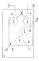
- Fig. 2 depicts a simplified block diagram showing a configuration of a system for an overload protected switch for ATE according to an embodiment of the invention.
- the system comprises a measurement instrument mi, a device under test dut, an overload detection circuit oldc, and a current limiting switch circuit clsc.
- Said current limiting switch circuit clsc comprises a floating voltage source V1 to supply said current limiting switch circuit clsc, a protection core circuit pcc, a control switch S1 to set said protection core circuit pcc in an overload condition olcdn and an overload switch sol.
- Said overload switch sol electrically connects a device under test dut with a measurement instrument mi.
- Said protection core circuit pcc comprises exceeding threshold voltage detecting means etdms adapted for detecting a second voltage drop raise 2Vd exceeding a threshold voltage drop at said overload switch sol, and stabilizing means stbms adapted for stabilizing a current flow Istab to said overload detection circuit oldc, if said second voltage drop 2Vd exceeds said threshold voltage drop at said overload switch sol.
- said protection core circuit pcc comprises protecting means prtms adapted for protecting prot said floating voltage source V1 from being shorted in case of said protection core circuit pcc being set into said overload condition olcdn, and disconnecting means disms adapted for switching said overload switch sol, providing said disconnecting dis of said measurement instrument mi from the device under test dut in case of said protection core circuit pcc being set into said overload condition olcdn.
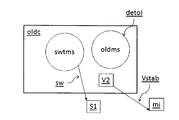
- Fig. 3 depicts a simplified block diagram showing a configuration of an overload detection circuit as part of a system for an overload protected switch for ATE according to an embodiment of the invention.
- Said overload detection circuit oldc comprises a voltage source V2 adapted for stabilizing the voltage drop Vstab of said measurement instrument mi, and overload detecting means oldms adapted for detecting an overload detol, if a first voltage drop of said overload detection circuit oldc exceeds said stabilized voltage drop Vstab.
- said overload detection circuit oldc comprises switching means swtms adapted for switching sw a control switch S1 in case said overload is detected detol.
- the whole circuitry clsc, pcc and oldc including the switches S1, sol and the floating voltage source V1 in combination may be used for performing three main functions: connecting and disconnecting the device under test dut to the measurement instrument mi, detecting an overload which could damage at least part of the ATE while testing a device under test dut and protecting the measurement instrument mi and the whole circuitry clsc, pcc and oldc including the switches S1, sol and the floating voltage source V1 from damage, if an overload occurs while testing the device under test dut.
- the current flow through the overload switch sol is limited to prevent short time damage to the system, and the overload switch is forced to disconnect the device under test dut from at least part of the system to prevent the system from being damaged by excessive power dissipation.
- program storage devices e.g., digital data storage media, which are machine or computer readable and encode machine-executable or computer-executable programs of instructions, wherein said instructions perform some or all of the steps of said above-described methods.
- the program storage devices may be, e.g. digital memories, magnetic storage media such as a magnetic disks and magnetic tapes, hard drives, or optically readable digital data storage media.
- the embodiments are also intended to cover computers programmed to perform said steps of the above-described methods.
- any switches shown in the Figures are conceptual only. Their function may be carried out through the operation of program logic, through dedicated logic, through the interaction of program control and dedicated logic, or even manually, the particular technique being selectable by the implementer as more specifically understood from the context.
Landscapes
- Engineering & Computer Science (AREA)
- General Engineering & Computer Science (AREA)
- Physics & Mathematics (AREA)
- General Physics & Mathematics (AREA)
- Emergency Protection Circuit Devices (AREA)
Abstract
A method for an overload protected switch for automatic test equipment. Said method comprises at least the steps of: detecting an overload, if a first voltage drop (1Vd) in an overload detection circuit (oldc) exceeds a predetermined voltage drop (Vs). A protection core circuit (pcc) is been set in an overload condition (olcdn) in case said overload is detected, and detecting a second voltage drop raise (2Vd) exceeding a threshold voltage drop (Vt) at an overload switch (sol). A current flow to said overload detection circuit (oldc) is stabilized, if said second voltage drop (2Vd) exceeds said threshold voltage drop (Vt) at said overload switch (sol).
Description
The invention relates to an electronic switch for use in automatic test equipment (ATE) and/or other precision measurement equipment. The contents of the following international application under Patent Cooperation Treaty are incorporated herein by reference,
PCT/JP2011/000738 filed on February 9, 2011.
PCT/JP2011/000738 filed on February 9, 2011.
In ATE for testing of mixed signals and automotive semiconductor devices there is a growing demand for precise voltage, current and time measurements. On the other hand, there is a trend to higher voltages and higher currents that the device under test (DUT) can handle.
Typically, high voltage and high current capable ATE instruments and fragile precision ATE instruments are connected to the DUT for testing purposes. In case a DUT is defective or gets defective while under test, high voltages and/or currents might be transferred to the precision instruments and can damage or even destruct them.
Another critical part in ATE for testing such DUTs is the switch that connects and disconnects the ATE instrument to or from the DUT, respectively. Conventional ATE instruments use mechanical or reed relays in order to realize the switch functionality. Those relays have a limited lifetime and need to be replaced during ATE instruments lifetime. These relays are a critical part in ATE reliability, too, because they might damage the ATE, especially in case of appearance of higher currents.
In view of the background discussed above, the present invention provides an electronic circuit, for common use in ATE and/or other technical fields where signals have to be generated or measured precisely and the generating or measuring instrument has to be protected against high voltages and/or high currents.
A method and a system for an overload protected switch for automatic test equipment according to one embodiment of the present invention address the problems described above. Said method comprises at least the steps of: detecting an overload, if a first voltage drop in an overload detection circuit exceeds a predetermined voltage drop. A protection core circuit is set in an overload condition in case said overload is detected, and detecting a second voltage drop raise exceeding a threshold voltage drop at an overload switch. A current flow to said overload detection circuit is stabilized, if said second voltage drop exceeds said threshold voltage drop at said overload switch.
In ATE environments, a voltage drop in electronic circuitry typically means direct current voltage (DC). Typical operating voltages in ATE environments are between 3V and 40V. However also alternating current voltage (AC) as well as other voltages, lower 3V or above 40V are possible.
An overload condition means a voltage drop over an electronic component or over electronic components which exceeds a reference voltage. Exceeding a voltage means such a voltage, which is higher than a positive reference voltage or lower than a negative reference voltage. Such reference voltage may be for example a stabilized voltage or a threshold voltage. Of course such reference voltage in general has a range of tolerance, which may differ with the electronic components in the electronic circuits. Typical tolerance ranges are in between +/- 1% to +/- 10%, but these tolerance ranges may even be lower +/- 1% or higher than +/- 10%, and also depending on the voltage level of the reference voltage.
Such overload may be detected with an overload detection circuitry, which in general means any kind of electronic component or electronic circuit adapted for detecting or measuring such exceeding of a reference voltage.
While in overload condition, the protection core circuit reacts in a different manner than in normal state, which means for example, that in this circuit voltage drops may differ from each other, or that in this circuit different current paths are significant for the behaviour of the protection core circuit, depending on the condition/state in which the protection core circuit operates.
A switch in such electronic circuit may be any kind of electronic circuit/component, adapted for changing a voltage drop or current, depending on the condition in which the switch is operated.
With this embodiment of the invention an effective protection method may be obtained against critical voltage and/or current for a measurement instrument in ATE and similar environments.
In an embodiment of the present invention the method further comprises at least the step of: protecting a floating voltage source from being shorted in case of said protection core circuit being set into said overload condition.
Such floating voltage source may be used for providing electrical energy to the protection core circuit and/or even may be used for providing electrical energy to the current limiting switch circuit.
In another embodiment of the present invention the method further comprises at least the steps of: testing a device under test (DUT) and electrically disconnecting a measurement instrument from said device under test in case of said protection core circuit being set into said overload condition.
With this embodiment an effective protection method may be obtained against critical voltage and/or current for a measurement instrument in ATE and similar environments, while testing a DUT.
Further, another embodiment of the invention provides a system for an overload protected switch for ATE, comprising at least a measurement instrument and at least an overload detection circuit. The system furthermore comprises at least a current limiting switch circuit. Said measurement instrument comprises testing means adapted for testing at least one device under test. Said overload detection circuit comprises at least a voltage source adapted for stabilizing the voltage drop of said measurement instrument. Said overload detecting circuit furthermore comprises overload detecting means adapted for detecting an overload, if a first voltage drop of said overload detection circuit exceeds said predetermined voltage drop, and switching means adapted for switching a control switch in case said overload is detected. Said current limiting switch circuit comprises at least a floating voltage source to supply said current limiting switch circuit, and said control switch to set a protection core circuit in an overload condition. Said protection core circuit comprises exceeding threshold voltage detecting means adapted for detecting a second voltage drop raise exceeding a threshold voltage drop at an overload switch. Said protection core circuit furthermore comprises stabilizing means adapted for stabilizing a current flow to said overload detection circuit, if said second voltage drop exceeds said threshold voltage drop at said overload switch, and protecting means adapted for protecting said floating voltage source from being shorted in case of said protection core circuit being set into said overload condition. Said protection core circuit furthermore comprises said overload switch to electrically disconnect said measurement instrument from the device under test in case of said protection core circuit being set into said overload condition, and disconnecting means adapted for switching said overload switch, providing said disconnecting of said measurement instrument from the device under test in case of said protection core circuit being set into said overload condition.
The current limiting switch may be any kind of electronic circuit/component, able to regulate a current over an electronic circuit/component, such that variability of this current is minimized to a desired current tolerance. Stabilizing a current means such regulation.
With this embodiment an effective protection system may be obtained against critical voltage and/or current for a measurement instrument in ATE and similar environments.
In an embodiment of the present invention in said system said overload detecting means is adapted for detecting an overload, if a first voltage drop of said overload detection circuit exceeds an absolute value of said predetermined voltage drop. Furthermore, in said system said stabilizing means is adapted for stabilizing a current flow to said overload detection circuit, if said second voltage drop exceeds an absolute value of said threshold voltage drop at said overload switch, and said exceeding threshold voltage detecting means is adapted for detecting a second voltage drop raise exceeding an absolute value of said threshold voltage drop at said overload switch.
Exceeding an absolute value means exceeding an absolute value including its tolerance range.
With this embodiment an effective protection system may be obtained against critical voltage and/or current for a measurement instrument in ATE and similar environments, while also protecting the used protection circuitry from serious damage of its components.
In a further embodiment of the present invention in said system said control switch is galvanically isolated, and preferably comprises an optoelectronic coupler.
The galvanically isolated switch may also comprise any other electronic component/circuit, which provides electrical isolated voltage and/or current.
In another embodiment of the present invention in said system said floating voltage source preferably comprises a solar cell.
With both these embodiments, undesired feedbacks in the circuitry may be avoided or at least minimized. This may contribute to system reliability.
In another embodiment of the present invention said measurement instrument comprises a buffer for additionally protecting said measurement instrument from overload.
In another embodiment of the present invention said overload switch comprises a transistor.
In another embodiment of the present invention said overload switch comprises a MOSFET.
Generally, said electronic switch may comprise any transistor, preferably any FET known to the man skilled in the art. However, according to an embodiment of the invention, each of said electronic switches comprises a MOSFET. It is further preferred that at least one of said electronic switches comprises a MOSFET. In another embodiment, the electronic switch comprises a DGMOSFET, FREDFET, HEMT, IGBT, JFET, MESFET, MODFET, NOMFET and/or an OFET. Such embodiments may have different advantages, like for example very fast recovery (turn-off) of the body diode of the FET, very fast switching transistors or low-cost electronic circuits, and may contribute to an increase in systems lifetime.
If an overload is detected, the reaction on this overload must be within a defined period of time after detection of the overload. Otherwise the transistors could be damaged because of high power dissipation.
In another embodiment of the present invention said system comprises said device under test, whereas said device under test comprises at least an input for a low voltage source, and at least an output for a low voltage signal.
The low voltage source shall not limit the kind of DUTs which may be tested with such system. Even DUTs which comprise at least an input and/or output for a low voltage signal and/or an input and/or an output for a high voltage signal may be tested.
Low voltage typically means voltage level around 1 microvolt to 5V, while high voltage typically means voltage level above 5V up to 300V.
These and other aspects of the invention will be apparent from and elucidated with reference to the embodiments described hereinafter.
The embodiments of the invention will now be described with reference to preferred embodiments which are not intended to limit the scope of the present invention but for exemplifying the invention. Not all of the features and combinations thereof described in the embodiment are necessarily essential to the invention.
In this specification, a "condition where a member A is connected to a member B" refers to the condition where the member A and the member B are physically connected to each other directly and to the condition where the member A and the member B are connected indirectly via other members that do not affect the electrical connection. Similarly, a "condition where a member C is provided between the member A and the member B" refers to, in addition to the condition where the member A and the member C or the member B and the member C are connected to one another directly, the condition where the members are connected indirectly via other members that do not affect the electrical connection.
The embodiments explained in the following relate to test equipment, and more specifically, to automatic test equipment (ATE) for testing a device under test (DUT).
Fig. 1 depicts a simplified block diagram showing a configuration of an overload protected switch circuit according to an embodiment of the invention. A device under test dut is connected to a measurement instrument mi via a current limiting switch circuit clsc and an overload detection circuit oldc.
Said current limiting switch circuit clsc comprises two switches, a protection core circuit pcc and a floating voltage source V1. Said floating voltage source V1 provides the protection core circuit pcc with electrical energy, while the first switch S1 disconnects said floating voltage source V1 from the protection core circuit pcc, in case a second voltage drop raise is detected, that exceeds a threshold voltage drop at the second switch sol.
Said second switch sol electrically connects the device under test dut to the measurement instrument mi and disconnects the device under test dut from the measurement instrument mi, in case an overload is detected.
Fig. 2 depicts a simplified block diagram showing a configuration of a system for an overload protected switch for ATE according to an embodiment of the invention. The system comprises a measurement instrument mi, a device under test dut, an overload detection circuit oldc, and a current limiting switch circuit clsc.
Said current limiting switch circuit clsc comprises a floating voltage source V1 to supply said current limiting switch circuit clsc, a protection core circuit pcc, a control switch S1 to set said protection core circuit pcc in an overload condition olcdn and an overload switch sol.
Said overload switch sol electrically connects a device under test dut with a measurement instrument mi.
Said protection core circuit pcc comprises exceeding threshold voltage detecting means etdms adapted for detecting a second voltage drop raise 2Vd exceeding a threshold voltage drop at said overload switch sol, and stabilizing means stbms adapted for stabilizing a current flow Istab to said overload detection circuit oldc, if said second voltage drop 2Vd exceeds said threshold voltage drop at said overload switch sol.
Furthermore, said protection core circuit pcc comprises protecting means prtms adapted for protecting prot said floating voltage source V1 from being shorted in case of said protection core circuit pcc being set into said overload condition olcdn, and disconnecting means disms adapted for switching said overload switch sol, providing said disconnecting dis of said measurement instrument mi from the device under test dut in case of said protection core circuit pcc being set into said overload condition olcdn.
Fig. 3 depicts a simplified block diagram showing a configuration of an overload detection circuit as part of a system for an overload protected switch for ATE according to an embodiment of the invention. Said overload detection circuit oldc comprises a voltage source V2 adapted for stabilizing the voltage drop Vstab of said measurement instrument mi, and overload detecting means oldms adapted for detecting an overload detol, if a first voltage drop of said overload detection circuit oldc exceeds said stabilized voltage drop Vstab.
Furthermore, said overload detection circuit oldc comprises switching means swtms adapted for switching sw a control switch S1 in case said overload is detected detol.
Thus the whole circuitry clsc, pcc and oldc including the switches S1, sol and the floating voltage source V1 in combination may be used for performing three main functions: connecting and disconnecting the device under test dut to the measurement instrument mi, detecting an overload which could damage at least part of the ATE while testing a device under test dut and protecting the measurement instrument mi and the whole circuitry clsc, pcc and oldc including the switches S1, sol and the floating voltage source V1 from damage, if an overload occurs while testing the device under test dut.
When an overload is detected, the current flow through the overload switch sol is limited to prevent short time damage to the system, and the overload switch is forced to disconnect the device under test dut from at least part of the system to prevent the system from being damaged by excessive power dissipation.
While the embodiment of the invention has been illustrated and described in detail in the drawings and foregoing description, such illustration and description are to be considered illustrative or exemplary and not restrictive; the invention is not limited to the disclosed embodiments.
Other variations to the disclosed embodiments can be understood and effected by those skilled in the art in practicing the claimed invention, from a study of the drawings, the disclosure, and the appended claims. In the claims, the word "comprising" does not exclude other elements or steps, and the indefinite article "a" or "an" does not exclude a plurality. The mere fact that certain measures are recited in mutually different dependent claims does not indicate that a combination of these measures cannot be used to advantage. Any reference signs in the claims should not be construed as limiting the scope.
A person of skill in the art would readily recognize that steps of various above-described methods can be performed by programmed computers. Herein, some embodiments are also intended to cover program storage devices, e.g., digital data storage media, which are machine or computer readable and encode machine-executable or computer-executable programs of instructions, wherein said instructions perform some or all of the steps of said above-described methods. The program storage devices may be, e.g. digital memories, magnetic storage media such as a magnetic disks and magnetic tapes, hard drives, or optically readable digital data storage media. The embodiments are also intended to cover computers programmed to perform said steps of the above-described methods.
The description and drawings merely illustrate the principles of the invention. It will thus be appreciated that those skilled in the art will be able to devise various arrangements that, although not explicitly described or shown herein, embody the principles of the invention and are included within its spirit and scope. Furthermore, all examples recited herein are principally intended expressly to be only for pedagogical purposes to aid the reader in understanding the principles of the invention and the concepts contributed by the inventor(s) to furthering the art, and are to be construed as being without limitation to such specifically recited examples and conditions. Moreover, all statements herein reciting principles, aspects, and embodiments of the invention, as well as specific examples thereof, are intended to encompass equivalents thereof.
The functions of the various elements shown in the Figs may be provided through the use of dedicated hardware as well as hardware capable of executing software in association with appropriate software. When provided by a processor, the functions may be provided by a single dedicated processor, by a single shared processor, or by a plurality of individual processors, some of which may be shared. Moreover, explicit use of the term "processor" or "controller" should not be construed to refer exclusively to hardware capable of executing software, and may implicitly include, without limitation, digital signal processor (DSP) hardware, network processor, application specific integrated circuit (ASIC), field programmable gate array (FPGA), read only memory (ROM) for storing software, random access memory (RAM), and non volatile storage. Other hardware, conventional and/or custom, may also be included. Similarly, any switches shown in the Figures are conceptual only. Their function may be carried out through the operation of program logic, through dedicated logic, through the interaction of program control and dedicated logic, or even manually, the particular technique being selectable by the implementer as more specifically understood from the context.
It should be appreciated by those skilled in the art that any block diagrams herein represent conceptual views of illustrative circuitry embodying the principles of the invention.
Claims (10)
- A method for an overload protected switch for ATE, comprising the steps of:
- detecting an overload, if a first voltage drop (1Vd) in an overload detection circuit (oldc) exceeds a predetermined voltage drop (Vs),
- setting a protection core circuit (pcc) in an overload condition (olcdn) in case said overload is detected,
- detecting a second voltage drop raise (2Vd) exceeding a threshold voltage drop (Vt) at an overload switch (sol), and
- stabilizing a current flow (Istab) to said overload detection circuit (oldc), if said second voltage drop (2Vd) exceeds said threshold voltage drop (Vt) at said overload switch (sol). - The method according to claim 1, further comprising the step of:
- protecting a floating voltage source (V1) from being shorted in case of said protection core circuit (pcc) being set into said overload condition (olcdn). - The method according to claim 1, further comprising the steps of:
- testing a device under test (dut), and
- electrically disconnecting a measurement instrument (mi) from said device under test (dut) in case of said protection core circuit (pcc) being set into said overload condition (olcdn). - A system for an overload protected switch for ATE, comprising
- at least a measurement instrument (mi),
- at least an overload detection circuit (oldc), and
- at least a current limiting switch circuit (clsc),
said measurement instrument (mi) comprising
- testing means (tesms) adapted for testing at least one device under test (dut),
said overload detection circuit (oldc) comprising
- at least a voltage source (V2) adapted for stabilizing the voltage drop (Vstab) of said measurement instrument (mi), and
- overload detecting means (oldms) adapted for detecting an overload (detol), if a first voltage drop (1Vd) of said overload detection circuit (oldc) exceeds said stabilized voltage drop (Vstab), and
- switching means (swtms) adapted for switching a control switch (S1) in case said overload (detol) is detected,
said current limiting switch circuit (clsc) comprising
- at least a floating voltage source (V1) to supply said current limiting switch circuit (clsc),
- said control switch (S1) to set a protection core circuit (pcc) in an overload condition (olcdn),
- said overload switch (sol) to electrically disconnect said measurement instrument (mi) from the device under test (dut) in case of said protection core circuit (pcc) being set into said overload condition (olcdn), and
said protection core circuit (pcc) comprising,
- exceeding threshold voltage detecting means (etdms) adapted for detecting a second voltage drop raise (2Vd) exceeding a threshold voltage drop (Vt) at an overload switch (sol),
- stabilizing means (stbms) adapted for stabilizing a current flow (Istab) to said overload detection circuit (oldc), if said second voltage drop (2Vd) exceeds said threshold voltage drop (Vt) at said overload switch (sol),
- protecting means (prtms) adapted for protecting said floating voltage source (V1) from being shorted in case of said protection core circuit (pcc) being set into said overload condition (olcdn), and
- disconnecting means (disms) adapted for switching said overload switch (sol), providing said disconnecting of said measurement instrument (mi) from the device under test (dut) in case of said protection core circuit (pcc) being set into said overload condition (olcdn). - The system according to claim 4, whereby
- said overload detecting means (oldms) is adapted for detecting an overload, if a first voltage drop (1Vd) of said overload detection circuit (oldc) exceeds an absolute value of said stabilized voltage drop (Vstab),
- said stabilizing means (stbms) is adapted for stabilizing a current flow (Istab) to said overload detection circuit (oldc), if said second voltage drop (2Vd) exceeds an absolute value of said threshold voltage drop (Vt) at said overload switch (sol), and
- said exceeding threshold voltage detecting means (etdms) is adapted for detecting a second voltage drop raise (2Vd) exceeding an absolute value of said threshold voltage drop (Vt) at said overload switch (sol). - The system according to claim 4, wherein
said control switch (S1) is galvanically isolated, and
preferably comprises an optoelectronic coupler. - The system according to claim 4, wherein
said floating voltage source (V1) preferably comprises a solar cell. - The system according to claim 4, wherein
said measurement instrument (mi) comprises a buffer for additionally protecting said measurement instrument (mi) from overload. - The system according to claim 4, wherein
said overload switch (sol) comprises a transistor, preferably a MOSFET. - The system according to claim 4, wherein the system comprises the device under test (dut), that includes:
- at least an input for a low voltage source (lvs); and
- at least an output for a low voltage signal.
Applications Claiming Priority (2)
| Application Number | Priority Date | Filing Date | Title |
|---|---|---|---|
| JPPCT/JP2011/000738 | 2011-02-09 | ||
| JP2011000738 | 2011-02-09 |
Publications (1)
| Publication Number | Publication Date |
|---|---|
| WO2012107963A1 true WO2012107963A1 (en) | 2012-08-16 |
Family
ID=46638209
Family Applications (1)
| Application Number | Title | Priority Date | Filing Date |
|---|---|---|---|
| PCT/JP2011/000780 Ceased WO2012107963A1 (en) | 2011-02-09 | 2011-02-10 | Overload protected switch |
Country Status (1)
| Country | Link |
|---|---|
| WO (1) | WO2012107963A1 (en) |
Citations (4)
| Publication number | Priority date | Publication date | Assignee | Title |
|---|---|---|---|---|
| US5250893A (en) * | 1992-01-31 | 1993-10-05 | Tegam, Inc. | Digital voltmeter |
| US6163445A (en) * | 1999-03-11 | 2000-12-19 | Fluke Corporation | Low-voltage test signal path protection circuit with extended bandwidth, overvoltage and transient protection |
| US20080055807A1 (en) * | 2004-09-28 | 2008-03-06 | Freescale Semiconductor Inc. | Power Switching Apparatus With Overload Protection |
| JP2011000738A (en) | 2009-06-16 | 2011-01-06 | Ricoh Co Ltd | Image forming apparatus |
-
2011
- 2011-02-10 WO PCT/JP2011/000780 patent/WO2012107963A1/en not_active Ceased
Patent Citations (4)
| Publication number | Priority date | Publication date | Assignee | Title |
|---|---|---|---|---|
| US5250893A (en) * | 1992-01-31 | 1993-10-05 | Tegam, Inc. | Digital voltmeter |
| US6163445A (en) * | 1999-03-11 | 2000-12-19 | Fluke Corporation | Low-voltage test signal path protection circuit with extended bandwidth, overvoltage and transient protection |
| US20080055807A1 (en) * | 2004-09-28 | 2008-03-06 | Freescale Semiconductor Inc. | Power Switching Apparatus With Overload Protection |
| JP2011000738A (en) | 2009-06-16 | 2011-01-06 | Ricoh Co Ltd | Image forming apparatus |
Similar Documents
| Publication | Publication Date | Title |
|---|---|---|
| ES2929540T3 (en) | Device for switching and protecting a load | |
| CA2762329C (en) | Testing of a transient voltage protection device | |
| EP2933646B1 (en) | Precision measurement of voltage drop across a semiconductor switching element | |
| US8582265B2 (en) | Protection circuit and method for electronic devices | |
| TWI410643B (en) | Semiconductor device test system having reduced current leakage | |
| CN112305393B (en) | Electronic test equipment and method of operating the same | |
| US20160141907A1 (en) | Battery management circuit and related techniques using mosfet power switch with intelligent switch control | |
| EP3396860A1 (en) | Electronic circuit | |
| US9720030B2 (en) | Systems and methods for testing a clamp function for insulated gate bipolar transistors | |
| US20150380926A1 (en) | Power converter, short circuit protection circuit, and control method | |
| CN106990344B (en) | monitoring device and monitoring method | |
| Yu et al. | Short-circuit capability: benchmarking SiC and GaN devices with Si-based technologies | |
| Kumar et al. | An intelligent medium voltage gate driver with enhanced short circuit protection scheme for 10kV 4H-SiC MOSFETs | |
| Xu et al. | Integrated high-speed over-current protection circuit for GaN power transistors | |
| US9863999B2 (en) | Circuit and method for inspecting semiconductor device | |
| US9673609B2 (en) | Self-test of over-current fault detection | |
| JP2013257177A (en) | Semiconductor tester | |
| CA2975741A1 (en) | Surge protection circuit | |
| Aeloiza et al. | An experimental demonstration of short circuit protection of SiC Devices | |
| US11585844B1 (en) | Systems, circuits, and methods to detect gate-open failures in MOS based insulated gate transistors | |
| US11054444B2 (en) | System and method for limiting voltage | |
| EP3540451B1 (en) | Voltage sensing | |
| US9778666B2 (en) | Dynamic current limit apparatus and method | |
| CN102565575B (en) | Testing apparatus | |
| ES2850351T3 (en) | Procedure for detecting a short circuit in an electrical circuit comprising an IGBT type transistor and associated control device |
Legal Events
| Date | Code | Title | Description |
|---|---|---|---|
| 121 | Ep: the epo has been informed by wipo that ep was designated in this application |
Ref document number: 11707927 Country of ref document: EP Kind code of ref document: A1 |
|
| NENP | Non-entry into the national phase |
Ref country code: DE |
|
| 122 | Ep: pct application non-entry in european phase |
Ref document number: 11707927 Country of ref document: EP Kind code of ref document: A1 |
|
| NENP | Non-entry into the national phase |
Ref country code: JP |