WO2012105414A1 - Gas superheater and superheater connecting body - Google Patents
Gas superheater and superheater connecting body Download PDFInfo
- Publication number
- WO2012105414A1 WO2012105414A1 PCT/JP2012/051697 JP2012051697W WO2012105414A1 WO 2012105414 A1 WO2012105414 A1 WO 2012105414A1 JP 2012051697 W JP2012051697 W JP 2012051697W WO 2012105414 A1 WO2012105414 A1 WO 2012105414A1
- Authority
- WO
- WIPO (PCT)
- Prior art keywords
- gas
- superheater
- outer tube
- tube
- heat generating
- Prior art date
Links
Images


Classifications
-
- H—ELECTRICITY
- H05—ELECTRIC TECHNIQUES NOT OTHERWISE PROVIDED FOR
- H05B—ELECTRIC HEATING; ELECTRIC LIGHT SOURCES NOT OTHERWISE PROVIDED FOR; CIRCUIT ARRANGEMENTS FOR ELECTRIC LIGHT SOURCES, IN GENERAL
- H05B3/00—Ohmic-resistance heating
- H05B3/40—Heating elements having the shape of rods or tubes
- H05B3/42—Heating elements having the shape of rods or tubes non-flexible
- H05B3/44—Heating elements having the shape of rods or tubes non-flexible heating conductor arranged within rods or tubes of insulating material
-
- C—CHEMISTRY; METALLURGY
- C01—INORGANIC CHEMISTRY
- C01B—NON-METALLIC ELEMENTS; COMPOUNDS THEREOF; METALLOIDS OR COMPOUNDS THEREOF NOT COVERED BY SUBCLASS C01C
- C01B33/00—Silicon; Compounds thereof
- C01B33/02—Silicon
- C01B33/021—Preparation
- C01B33/027—Preparation by decomposition or reduction of gaseous or vaporised silicon compounds other than silica or silica-containing material
- C01B33/033—Preparation by decomposition or reduction of gaseous or vaporised silicon compounds other than silica or silica-containing material by reduction of silicon halides or halosilanes with a metal or a metallic alloy as the only reducing agents
-
- F—MECHANICAL ENGINEERING; LIGHTING; HEATING; WEAPONS; BLASTING
- F27—FURNACES; KILNS; OVENS; RETORTS
- F27D—DETAILS OR ACCESSORIES OF FURNACES, KILNS, OVENS, OR RETORTS, IN SO FAR AS THEY ARE OF KINDS OCCURRING IN MORE THAN ONE KIND OF FURNACE
- F27D99/00—Subject matter not provided for in other groups of this subclass
- F27D99/0001—Heating elements or systems
- F27D99/0006—Electric heating elements or system
-
- H—ELECTRICITY
- H05—ELECTRIC TECHNIQUES NOT OTHERWISE PROVIDED FOR
- H05B—ELECTRIC HEATING; ELECTRIC LIGHT SOURCES NOT OTHERWISE PROVIDED FOR; CIRCUIT ARRANGEMENTS FOR ELECTRIC LIGHT SOURCES, IN GENERAL
- H05B2203/00—Aspects relating to Ohmic resistive heating covered by group H05B3/00
- H05B2203/022—Heaters specially adapted for heating gaseous material
Definitions
- the present invention relates to, for example, a gas superheater used for heating a heated gas introduced into an electric furnace to a high temperature and a superheater assembly.
- a zinc reduction method for producing high-purity polycrystalline silicon by reducing silicon tetrachloride with metallic zinc has attracted attention as a method for producing polycrystalline silicon as a raw material for silicon solar cells.
- silicon tetrachloride and zinc as raw materials are vaporized at 900 to 1,100 ° C. and heated to cause a gas phase reduction reaction.
- silicon tetrachloride Since silicon tetrachloride has a boiling point of 58 ° C, it can be vaporized relatively easily. However, it reacts violently with water and is corrosive. Care should be taken in handling such as selection.
- Patent Document 1 discloses a gas heater that obtains a high-temperature gas by heating a metal resistor to a high temperature by direct energization, and bringing the gas directly into contact with the metal resistor that has reached a high temperature.
- Patent Document 2 a heating element including a heat generating part formed in a spiral shape and an electrode terminal taken out from the heat generating part in a protective tube disposed through the inner wall of the furnace, A gas heating device is disclosed that is inserted so as to be located inside the furnace. In this gas heating apparatus, gas or air is guided to a heat generating portion formed in a spiral shape and heated, and the heated gas or air is discharged into the furnace.
- this gas heating device has a structure in which the heat generating part penetrates the furnace inner wall, the maximum length of the heat generating part is limited by the thickness of the furnace inner wall, and as a result, sufficient control of the heating temperature is achieved. There is a problem that it is difficult.
- the present invention has been made in order to solve the conventional problems in a gas superheater for heating a gas supplied to a reactor or the like to a high temperature, and its purpose is to provide a corrosive and reactive gas. It is an object of the present invention to provide a gas superheater and a superheater assembly that can be heated under close control to a target temperature of 900 to 1,100 ° C.
- an object of the present invention is to provide a gas superheater and a superheater assembly.
- a gas superheater comprises: A gas superheater for heating a gas to a high temperature, The gas superheater, An outer tube having a gas inlet and a gas outlet; A plurality of heat generating tubes disposed in the longitudinal direction of the outer tube, and containing a heat generating element therein; It is characterized by comprising at least.
- a side plate in which a hole for inserting the heat generating tube is formed in advance is disposed at both ends of the outer tube, and the heat generating tube is inserted into the hole.
- the heating tube is formed longer than the entire length of the outer tube, A heating tube having a length longer than that of the outer tube may be extended from one end of the outer tube to the other end. Alternatively, the heating tube is less than half the length of the outer tube, The exothermic tube having a length of half or less may be inserted from both ends of the outer tube to the vicinity of the center of the outer tube.
- an external heating means is disposed on the outer periphery of the outer tube.
- the heating element is preferably a resistance heating element made of metal or ceramic.
- a substantially semicircular rectifying plate is disposed on the inner wall of the outer tube at a predetermined interval, and the rectifying plates adjacent to each other are arranged on one side of the inner wall of the outer tube. It is preferable that they are alternately arranged on the side and the other side.
- the heated gas flowing inside collides with the rectifying plate and the flow path is changed, so that a long flow path for the gas in the outer tube can be secured, and the entire gas is uniformly heated. be able to.
- the material of the outer tube and the heating tube is quartz.
- the heated gas is preferably silicon tetrachloride.
- the superheater coupling body of the present invention is configured by connecting a plurality of the above gas superheaters.
- the gas supplied to the reactor or the like can be heated while strictly controlling to the target temperature. Further, even when a corrosive gas is heated, a heating element such as a coil is not corroded by the gas.
- the length of the heat generating part can be set freely, the control of the heating temperature is easy.
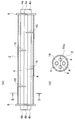
- FIG. 1 is an exploded perspective view showing a main part of a gas superheater according to an embodiment of the present invention.
- 2A is a schematic cross-sectional view in a state where the gas superheater of FIG. 1 is assembled
- FIG. 2B is a cross-sectional view in the direction of the line BB in FIG. 2A.
- FIG. 3 is a perspective view showing another aspect of the side plate shown in FIG.
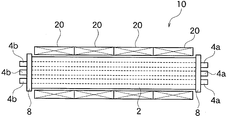
- FIG. 4 is a schematic front view of a gas superheater according to another embodiment of the present invention.
- FIG. 5 is a schematic cross-sectional view of a gas superheater according to still another embodiment of the present invention.
- FIG. 6 is a schematic cross-sectional view of a gas superheater according to still another embodiment of the present invention.
- FIG. 1 is an exploded perspective view of a gas superheater according to an embodiment of the present invention
- FIG. 2A is a schematic cross-sectional view of the assembled gas superheater of FIG.
- FIG. 2B is a schematic cross-sectional view in the direction of line BB in FIG.
- the gas to be heated is silicon tetrachloride used for producing high-purity polycrystalline silicon.
- the gas superheater 10 of the present embodiment includes a substantially cylindrical outer tube 2, a plurality of (four in this embodiment) heat generating tubes 4 disposed at both ends projecting from the outer tube 2, It has a plurality of heating elements 6 housed inside the heating tube 4. Further, both end portions of the outer tube 2 are sealed by the side plates 8 and 8 after the heating tube 4 is accommodated.
- a gas inlet 2a and a gas outlet 2b are formed at both ends of the outer tube 2, respectively.
- one side plate 8 may be disposed at each end of the outer tube 2, but in order to maintain strength, an inner closing plate 8a and an outer closing plate 8b, as in the side plate 8 'shown in FIG. It is also possible to adopt a structure in which a heat insulating material such as a ceramic fiber blanket is loaded between them.
- Quartz, silicon carbide, silicon nitride or the like having corrosion resistance and heat resistance can be used as the material of the outer tube 2, the heat generating tube 4, and the side plate 8 (8 '). Quartz is suitable when the gas to be handled is silicon tetrachloride as in this embodiment.
- the number of heating tubes 4 and heating elements 6 housed in the outer tube 2 is usually 2 to 10, but this number is not particularly limited and is appropriately determined according to the required heat capacity.
- the respective heat generating tubes 4 are arranged substantially equally apart.
- the exothermic tube 4 has a length in which both end portions 4a and 4b project to the outside through both side plates 8 and 8, and the heating element 6 extends from either one of the projecting end portions 4a and 4b. Is inserted into the heat generating tube 4 and accommodated.
- the heating element 6 can be a resistance heater such as Kanthal alloy, nickel-chromium alloy, or silicon carbide.
- a resistance heater such as Kanthal alloy, nickel-chromium alloy, or silicon carbide.
- As the shape of the heater a coil shape, a rod shape, a spiral shape, a cylindrical shape, or the like can be used as appropriate.
- the outer tube 2 containing the heat generating tube 4 is usually installed horizontally, but can also be installed vertically or obliquely depending on the installation space.
- the heat generating tube 4 longer than the outer tube 2 is accommodated in the outer tube 2, but instead of this, two divided bodies can be arranged linearly. That is, when the length of the heating element 6 or the heating tube 4 is limited, as shown in FIG. 5, two bottomed cylindrical heating tubes 14 with one end sealed in advance are prepared as a set. The end portions 14a on the closed side of the heat generating tubes 14 and 14 are inserted into the outer tube 2 from both sides in a substantially straight line, and the end portions 14b on the open side are inserted into the side plates 8 and 8 of the outer tube 2. It is also possible to have a structure protruding from the outside. In FIG.
- the end portions 14 a and 14 a on the closed side of the pair of heat generating tubes 14 and 14 are arranged adjacent to each other at a predetermined interval in the central portion of the outer tube 2.
- the distance between the end portions 14a of the heat generating tubes 14 adjacent to each other is not particularly limited, but it is preferable to secure about 1 to 10 cm.
- a plurality (four in the embodiment) of rectifying plates 16 are provided on the inner wall of the outer tube 2 with respect to the axial direction of the outer tube 2. Are arranged in a vertical direction. These rectifying plates 16 have a substantially semicircular shape, and in a cross-sectional view of the outer tube 2 provided with the rectifying plate 16, a space on the opposite side to the side where the rectifying plate 16 is provided is a substantially semicircular notch. Part 16a is formed. The cutout portion 16 a may be arcuate and the shape is determined by the shape of the rectifying plate 16.
- the heat generating tube 4 has a structure penetrating each rectifying plate 16, and the heat generating tube 4 and the rectifying plate 16 in the penetrating portion are integrated by fixing several points by welding.
- the gas passes through the inside of the outer tube 2 through the notch 16a. It is preferable that the notch positions of the rectifying plates 16 adjacent to each other are alternated by 180 degrees. As a result, the gas passing therethrough changes the flow path while hitting the rectifying plate 16, and the passage distance in the outer tube 2 is ensured to be long, whereby heat exchange can be performed efficiently.
- the distance between the rectifying plates adjacent to each other is preferably 10 to 30 cm.
- Quartz, silicon carbide, silicon nitride, or the like can be used as the material of the rectifying plate 16. Quartz is preferred when the gas to be handled is silicon tetrachloride.
- the outer periphery of the outer tube 2 may be covered with a heat insulating material, in order to reduce heat dissipation loss and increase thermal efficiency, for example, as in the other embodiment shown in FIG.
- the external heating means 20 is disposed in each of the defined areas and heated from the outside to the inside.
- the heating capacity of the internal heating tube 4 can be set to be small accordingly, so that the heat exchanger can be made more compact than before.
- a resistance heater such as a cantal alloy, a nickel chromium alloy, or silicon carbide can be used.
- each region of the external heating means 20 is preferably larger on the gas inlet 2a side shown in FIG. 1 than on the gas outlet 2b side.
- silicon tetrachloride gas to be heated is introduced into the outer tube 2 from the gas inlet 2a, and if the heating element 6 generates heat to a high temperature when energized, the heated gas is The temperature gradually increases and the air flows into the downstream side of the outer tube 2 while colliding with the rectifying plate 16, and finally reaches a temperature of 900 to 1,100 ° C. and is ejected to the outside from the gas outlet 2b.
- silicon tetrachloride gas heated to a predetermined temperature can be supplied into the furnace.
- the length of the heat generating part is not limited by the thickness of the furnace inner wall, and can be designed to a free length.
- the gas superheater 10 according to one embodiment of the present invention has been described above, but the present invention is not limited to the above embodiment.
- two or three or more gas superheaters 10 described above can be connected as shown in FIG.
- the superheater connector 30 for example, corrosive and reactive gas can be heated under strictly control to a target temperature of 900 to 1,100 ° C.
- the raw material silicon tetrachloride gas can be heated to a target temperature of 900 to 1,100 ° C. with strict control and supplied to the reduction reactor. is there.
- the gas superheater 10 is not limited to heating silicon tetrachloride gas, and can be used as a superheater for various gases.
- an external heater (external heating means 20) composed of upper and lower divided four units was installed on the outer periphery of the outer tube 2.
- the capacity of the external heater was set to 20.5 kW in the two zones on the gas inlet side and 10 kW in the two zones on the gas outlet side.
- the respective heaters of the gas superheater configured as described above were energized, and silicon tetrachloride gas heated to 80 ° C. was introduced from the gas inlet 2a side at a flow rate of 600 kg / hr.
- the temperature on the gas outlet 2b side of the silicon tetrachloride gas was measured and found to be 970 ° C.
- the gas superheater 10 of the present invention can obtain a high-temperature gas under a strict temperature control with a compact configuration.
Landscapes
- Engineering & Computer Science (AREA)
- Chemical & Material Sciences (AREA)
- Organic Chemistry (AREA)
- Mechanical Engineering (AREA)
- General Engineering & Computer Science (AREA)
- Inorganic Chemistry (AREA)
- Silicon Compounds (AREA)
- Physical Or Chemical Processes And Apparatus (AREA)
- Furnace Details (AREA)
Abstract
[Problem]
To provide a gas superheater and a gas superheater connecting body with which a corrosive and reactive gas, and particularly a raw material silicon tetrachloride gas in a zinc reduction method that manufactures high-purity silicon, can be strictly controlled and heated to a target temperature of 900-1,100°C.
[Solution]
A gas superheater characterized in that multiple heat-generating tubes housing heat-generating bodies are arranged in the lengthwise direction within an outer cylindrical tube equipped with a gas inflow port and a gas outflow port.
Description
本発明は例えば、電気炉内に導入される被加熱ガスを高温に加熱するのに使用されるガス過熱器および過熱器連結体に関する。
The present invention relates to, for example, a gas superheater used for heating a heated gas introduced into an electric furnace to a high temperature and a superheater assembly.
近年、シリコン太陽電池の原料となる多結晶シリコンの製造法として四塩化珪素を金属亜鉛で還元して高純度多結晶シリコンを製造する亜鉛還元法が注目されている。
亜鉛還元法においては、原料となる四塩化珪素及び亜鉛は900~1,100℃に気化、加熱して気相還元反応を行わせる。 In recent years, a zinc reduction method for producing high-purity polycrystalline silicon by reducing silicon tetrachloride with metallic zinc has attracted attention as a method for producing polycrystalline silicon as a raw material for silicon solar cells.
In the zinc reduction method, silicon tetrachloride and zinc as raw materials are vaporized at 900 to 1,100 ° C. and heated to cause a gas phase reduction reaction.
四塩化珪素の沸点は58℃であるので、比較的容易に気化させることができるが、水と激しく反応し、腐食性もあるので1,000℃程度までの加熱には、装置内雰囲気及び装置材質の選定など取り扱いに注意を要する。
Since silicon tetrachloride has a boiling point of 58 ° C, it can be vaporized relatively easily. However, it reacts violently with water and is corrosive. Care should be taken in handling such as selection.
ところで、特許文献1には、直接通電により金属抵抗体を高温に加熱し、その高温になった金属抵抗体にガスを直接接触させることで高温のガスを得るガス加熱器が開示されている。
By the way, Patent Document 1 discloses a gas heater that obtains a high-temperature gas by heating a metal resistor to a high temperature by direct energization, and bringing the gas directly into contact with the metal resistor that has reached a high temperature.
しかしながら、四塩化珪素のような腐食性のガスを加熱する場合は、金属抵抗体がそのガスによって腐食されるなどの問題がある。
一方、特許文献2には、炉内壁を貫通して配置された保護管内に、スパイラル状に形成した発熱部とこの発熱部から取り出された電極端子とを備えた発熱体を、この発熱部が炉内側に位置するように挿通してなるガス加熱装置が開示されている。
そしてこのガス加熱装置では、ガス或いは空気を、スパイラル状に形成された発熱部に導いて加熱し、加熱後のガス或いは空気を炉内に放出するようにしている。
このガス加熱装置は、発熱部が炉内壁を貫通して構成される構造のため、発熱部の最大の長さが、炉内壁の厚さに制限され、結果として、加熱温度の十分な制御が困難であるという問題がある。 However, when a corrosive gas such as silicon tetrachloride is heated, there is a problem that the metal resistor is corroded by the gas.
On the other hand, inPatent Document 2, a heating element including a heat generating part formed in a spiral shape and an electrode terminal taken out from the heat generating part in a protective tube disposed through the inner wall of the furnace, A gas heating device is disclosed that is inserted so as to be located inside the furnace.
In this gas heating apparatus, gas or air is guided to a heat generating portion formed in a spiral shape and heated, and the heated gas or air is discharged into the furnace.
Since this gas heating device has a structure in which the heat generating part penetrates the furnace inner wall, the maximum length of the heat generating part is limited by the thickness of the furnace inner wall, and as a result, sufficient control of the heating temperature is achieved. There is a problem that it is difficult.
一方、特許文献2には、炉内壁を貫通して配置された保護管内に、スパイラル状に形成した発熱部とこの発熱部から取り出された電極端子とを備えた発熱体を、この発熱部が炉内側に位置するように挿通してなるガス加熱装置が開示されている。
そしてこのガス加熱装置では、ガス或いは空気を、スパイラル状に形成された発熱部に導いて加熱し、加熱後のガス或いは空気を炉内に放出するようにしている。
このガス加熱装置は、発熱部が炉内壁を貫通して構成される構造のため、発熱部の最大の長さが、炉内壁の厚さに制限され、結果として、加熱温度の十分な制御が困難であるという問題がある。 However, when a corrosive gas such as silicon tetrachloride is heated, there is a problem that the metal resistor is corroded by the gas.
On the other hand, in
In this gas heating apparatus, gas or air is guided to a heat generating portion formed in a spiral shape and heated, and the heated gas or air is discharged into the furnace.
Since this gas heating device has a structure in which the heat generating part penetrates the furnace inner wall, the maximum length of the heat generating part is limited by the thickness of the furnace inner wall, and as a result, sufficient control of the heating temperature is achieved. There is a problem that it is difficult.
本発明は、反応器等へ供給するガスを高温に加熱するためのガス過熱器における従来の問題点を解決するためになされたものであり、その目的は、腐食性、反応性のあるガスを900~1,100℃の目標温度まで厳密に制御して加熱することを可能とするガス過熱器および過熱器連結体を提供することにある。
The present invention has been made in order to solve the conventional problems in a gas superheater for heating a gas supplied to a reactor or the like to a high temperature, and its purpose is to provide a corrosive and reactive gas. It is an object of the present invention to provide a gas superheater and a superheater assembly that can be heated under close control to a target temperature of 900 to 1,100 ° C.
特には、本発明は高純度シリコンを製造する亜鉛還元法において、原料四塩化珪素ガスを、900~1,100℃の目標温度まで厳密に制御して加熱し、還元反応器へ供給することを可能とするガス過熱器および過熱器連結体を提供することにある。
In particular, according to the present invention, in the zinc reduction method for producing high-purity silicon, it is possible to heat the raw material silicon tetrachloride gas to a target temperature of 900 to 1,100 ° C., and to supply it to the reduction reactor. An object of the present invention is to provide a gas superheater and a superheater assembly.
上記目的を達成するための本発明に係るガス過熱器は、
ガスを高温に加熱するためのガス過熱器であって、
前記ガス過熱器が、
ガス流入口及びガス流出口を備えた外筒管と、
前記外筒管の長尺方向に配置され、内部に発熱体が収容された複数の発熱管と、
から少なくとも構成されていることを特徴としている。 In order to achieve the above object, a gas superheater according to the present invention comprises:
A gas superheater for heating a gas to a high temperature,
The gas superheater,
An outer tube having a gas inlet and a gas outlet;
A plurality of heat generating tubes disposed in the longitudinal direction of the outer tube, and containing a heat generating element therein;
It is characterized by comprising at least.
このようなガス過熱器によれば、発熱体がガスに接触することがないことから腐食の虞がない。
ここで、前記外筒管の両端部には、前記発熱管を挿入するための孔が予め形成された側板が配設され、前記発熱管は前記孔に挿入されていることが好ましい。 According to such a gas superheater, there is no possibility of corrosion because the heating element does not contact the gas.
Here, it is preferable that a side plate in which a hole for inserting the heat generating tube is formed in advance is disposed at both ends of the outer tube, and the heat generating tube is inserted into the hole.
このように形成されていれば、加熱エネルギーの有効利用が図られるとともに、発熱管を安定した姿勢で保持することができる。
さらに前記発熱管は、前記外筒管の全長より長く形成されたものであり、
前記外筒管より長い長さの発熱管が、前記外筒管の一方の端部から他方の端部に渡って差し渡されたものであっても良い。
あるいは前記発熱管は、前記外筒管の長さに対して半分以下の長さであり、
前記半分以下の長さの発熱管が、前記外筒管の両端部から、前記外筒管の中央付近まで挿入されたものであっても良い。 If formed in this way, the heating energy can be effectively used and the heating tube can be held in a stable posture.
Furthermore, the heating tube is formed longer than the entire length of the outer tube,
A heating tube having a length longer than that of the outer tube may be extended from one end of the outer tube to the other end.
Alternatively, the heating tube is less than half the length of the outer tube,
The exothermic tube having a length of half or less may be inserted from both ends of the outer tube to the vicinity of the center of the outer tube.
このように設計変更が容易であるため、発熱管の長さにより、片側から挿入するか、あるいは両側から挿入するかのいずれかを選択することができる。
また、本発明では、前記外筒管の外周に外部加熱手段が配設されていることが好ましい。 Since the design can be easily changed in this way, it is possible to select either one of insertion from one side or both sides depending on the length of the heat generating tube.
In the present invention, it is preferable that an external heating means is disposed on the outer periphery of the outer tube.
このように、外部加熱手段を配置すれば、内側と外側とで加熱することができるので、加熱効果が良好である。
さらに、前記発熱体は、金属又はセラミックよりなる抵抗発熱体であることが好ましい。 Thus, if an external heating means is arrange | positioned, since it can heat by an inner side and an outer side, a heating effect is favorable.
Furthermore, the heating element is preferably a resistance heating element made of metal or ceramic.
さらに、前記発熱体は、金属又はセラミックよりなる抵抗発熱体であることが好ましい。 Thus, if an external heating means is arrange | positioned, since it can heat by an inner side and an outer side, a heating effect is favorable.
Furthermore, the heating element is preferably a resistance heating element made of metal or ceramic.
このような構成であれば、発熱効率が良好であるとともに温度調整が容易である。
さらに、本発明では、前記外筒管の内壁に、略半円状の整流板が所定間隔離間して配設されているとともに、相隣合う前記整流板が、前記外筒管の内壁の一方側および他方側に互い違いに配設されていることが好ましい。 With such a configuration, heat generation efficiency is good and temperature adjustment is easy.
Further, in the present invention, a substantially semicircular rectifying plate is disposed on the inner wall of the outer tube at a predetermined interval, and the rectifying plates adjacent to each other are arranged on one side of the inner wall of the outer tube. It is preferable that they are alternately arranged on the side and the other side.
このような構成であれば、内部を流れる加熱ガスが整流板に衝突し流路が代わることにより、外筒管内でのガスの流路を長く確保することができ、ガス全体を均一に加熱することができる。
With such a configuration, the heated gas flowing inside collides with the rectifying plate and the flow path is changed, so that a long flow path for the gas in the outer tube can be secured, and the entire gas is uniformly heated. be able to.
また、本発明では、前記外筒管及び前記発熱管の材質が石英であることが好ましい。
さらに、本発明では、前記加熱されるガスが、四塩化珪素であることが好ましい。
また、本発明の過熱器連結体は、上記いずれかのガス過熱器を、複数連結して構成されていることが好ましい。 In the present invention, it is preferable that the material of the outer tube and the heating tube is quartz.
Furthermore, in the present invention, the heated gas is preferably silicon tetrachloride.
Moreover, it is preferable that the superheater coupling body of the present invention is configured by connecting a plurality of the above gas superheaters.
本発明のガス過熱器および過熱器連結体によれば、反応器などへ供給するガスを目標温度にまで厳密に制御して加熱することができる。
また、腐食性のガスを加熱する場合であっても、コイルなどからなる発熱体がガスによって腐食されることがない。 According to the gas superheater and superheater assembly of the present invention, the gas supplied to the reactor or the like can be heated while strictly controlling to the target temperature.
Further, even when a corrosive gas is heated, a heating element such as a coil is not corroded by the gas.
さらに、発熱部の長さを自由に設定できるので、加熱温度の制御が容易である。
Furthermore, since the length of the heat generating part can be set freely, the control of the heating temperature is easy.
以下、本発明に係るガス過熱器を図面に基づいて説明する。
図1は本発明の一実施例に係るガス過熱器を分解して示した斜視図で、図2(A)は、図1のガス過熱器を組立てた状態での概略断面図で、図2(B)は図2(A)のB-B線方向の概略断面図である。なお、本実施例において、加熱されるガスは、高純度多結晶シリコンを製造するのに使用される四塩化珪素である。 Hereinafter, the gas superheater concerning the present invention is explained based on a drawing.
FIG. 1 is an exploded perspective view of a gas superheater according to an embodiment of the present invention, and FIG. 2A is a schematic cross-sectional view of the assembled gas superheater of FIG. FIG. 2B is a schematic cross-sectional view in the direction of line BB in FIG. In this embodiment, the gas to be heated is silicon tetrachloride used for producing high-purity polycrystalline silicon.
本実施例のガス過熱器10は、略円筒状の外筒管2と、外筒管2内に両端部が突出して配置される複数本(本実施例では4本)の発熱管4と、発熱管4の内部に収容される複数本の発熱体6とを有している。また、外筒管2の両端部は、発熱管4が収容された後、側板8,8により封止される。
The gas superheater 10 of the present embodiment includes a substantially cylindrical outer tube 2, a plurality of (four in this embodiment) heat generating tubes 4 disposed at both ends projecting from the outer tube 2, It has a plurality of heating elements 6 housed inside the heating tube 4. Further, both end portions of the outer tube 2 are sealed by the side plates 8 and 8 after the heating tube 4 is accommodated.
上記外筒管2の両端部には、それぞれガス流入口2aとガス流出口2bとが形成されている。
また、外筒管2の各端部に配置される側板8は一枚でも良いが、強度保持のため、図3に示した側板8'のように、内側閉止板8aと外側閉止板8bとからなる二重構造とし、これらの間にセラミックファイバーブランケットなどの断熱材を装填した構造とすることもできる。 Agas inlet 2a and a gas outlet 2b are formed at both ends of the outer tube 2, respectively.
In addition, oneside plate 8 may be disposed at each end of the outer tube 2, but in order to maintain strength, an inner closing plate 8a and an outer closing plate 8b, as in the side plate 8 'shown in FIG. It is also possible to adopt a structure in which a heat insulating material such as a ceramic fiber blanket is loaded between them.
また、外筒管2の各端部に配置される側板8は一枚でも良いが、強度保持のため、図3に示した側板8'のように、内側閉止板8aと外側閉止板8bとからなる二重構造とし、これらの間にセラミックファイバーブランケットなどの断熱材を装填した構造とすることもできる。 A
In addition, one
上記外筒管2と上記発熱管4と上記側板8(8')などの材質は耐食性で耐熱性を有する石英、炭化珪素、窒化珪素などを用いることができる。本実施例のように、扱うガスが四塩化珪素の場合は石英が好適である。
Quartz, silicon carbide, silicon nitride or the like having corrosion resistance and heat resistance can be used as the material of the outer tube 2, the heat generating tube 4, and the side plate 8 (8 '). Quartz is suitable when the gas to be handled is silicon tetrachloride as in this embodiment.
外筒管2内に収容する発熱管4ならびに発熱体6は、通常2本~10本であるが、この数は特に限定されるものではなく必要とする熱容量に応じて適宜決定される。図示した例では、それぞれの発熱管4が略均等に離間して配置されている。
The number of heating tubes 4 and heating elements 6 housed in the outer tube 2 is usually 2 to 10, but this number is not particularly limited and is appropriately determined according to the required heat capacity. In the illustrated example, the respective heat generating tubes 4 are arranged substantially equally apart.
発熱管4は、両側板8,8を貫通して両端部4a,4bが、外部に突出する長さを有しており、この突出した両端部4a,4bのいずれか一方から、発熱体6を発熱管4内に挿入して収容する構造となっている。
The exothermic tube 4 has a length in which both end portions 4a and 4b project to the outside through both side plates 8 and 8, and the heating element 6 extends from either one of the projecting end portions 4a and 4b. Is inserted into the heat generating tube 4 and accommodated.
発熱体6は、カンタル合金、ニッケルクロム合金、炭化珪素などの抵抗式ヒーターを用いることができる。ヒーターの形状は、コイル状、棒状、スパイラル状、円筒状等、適宜用いることができる。発熱管4を収容した外筒管2は、通常、水平に設置するが、設置スペースの都合により、垂直あるいは斜めに設置することもできる。
The heating element 6 can be a resistance heater such as Kanthal alloy, nickel-chromium alloy, or silicon carbide. As the shape of the heater, a coil shape, a rod shape, a spiral shape, a cylindrical shape, or the like can be used as appropriate. The outer tube 2 containing the heat generating tube 4 is usually installed horizontally, but can also be installed vertically or obliquely depending on the installation space.
図1のガス過熱器10では、外筒管2より長い発熱管4を外筒管2内に収容しているが、これに代え、2本の分割体を直線状に配置することもできる。
すなわち、発熱体6あるいは発熱管4の長さに制約がある場合などに、図5に示したように、予め一端が封止された有底筒状の発熱管14を2本組として用意し、これら発熱管14,14の閉鎖側の端部14aを、外筒管2の内部へ両側から略直線状に挿入し、開放側の各端部14bを外筒管2の両側板8,8から外部へ突出させた構造とすることもできる。
図5では、このような1対の発熱管14,14の閉鎖側の端部14a,14aが、外筒管2の中央部分で所定間隔離間して互いに隣り合う配置となっている。互いに隣り合う発熱管14の端部14a間の離間距離は特に限定されないが、1~10cm程度確保するとよい。 In thegas superheater 10 of FIG. 1, the heat generating tube 4 longer than the outer tube 2 is accommodated in the outer tube 2, but instead of this, two divided bodies can be arranged linearly.
That is, when the length of theheating element 6 or the heating tube 4 is limited, as shown in FIG. 5, two bottomed cylindrical heating tubes 14 with one end sealed in advance are prepared as a set. The end portions 14a on the closed side of the heat generating tubes 14 and 14 are inserted into the outer tube 2 from both sides in a substantially straight line, and the end portions 14b on the open side are inserted into the side plates 8 and 8 of the outer tube 2. It is also possible to have a structure protruding from the outside.
In FIG. 5, the end portions 14 a and 14 a on the closed side of the pair of heat generating tubes 14 and 14 are arranged adjacent to each other at a predetermined interval in the central portion of the outer tube 2. The distance between the end portions 14a of the heat generating tubes 14 adjacent to each other is not particularly limited, but it is preferable to secure about 1 to 10 cm.
すなわち、発熱体6あるいは発熱管4の長さに制約がある場合などに、図5に示したように、予め一端が封止された有底筒状の発熱管14を2本組として用意し、これら発熱管14,14の閉鎖側の端部14aを、外筒管2の内部へ両側から略直線状に挿入し、開放側の各端部14bを外筒管2の両側板8,8から外部へ突出させた構造とすることもできる。
図5では、このような1対の発熱管14,14の閉鎖側の端部14a,14aが、外筒管2の中央部分で所定間隔離間して互いに隣り合う配置となっている。互いに隣り合う発熱管14の端部14a間の離間距離は特に限定されないが、1~10cm程度確保するとよい。 In the
That is, when the length of the
In FIG. 5, the
一方、外筒管2の内壁には、図2(A),(B)に示したように、複数個(実施例では4個)の整流板16が、外筒管2の軸方向に対して垂直な方向に配置されている。これら整流板16は略半円状であり、整流板16が設けられた外筒管2の断面視において、整流板16が設けられた側と対向する逆側の空間が略半円状の切欠部16aを形成している。
なお、この切欠部16aは、円弧状であっても良く、形状は整流板16の形状によって決められるものである。
発熱管4はそれぞれの整流板16を貫通する構造となっており、貫通部の発熱管4と整流板16とは、溶接により数点を固着して一体化されている。なお、この切欠部16aを通してガスが外筒管2の内部を通過するようになっている。
互いに隣り合う整流板16の切欠位置は、180度互い違いになることが好ましい。これによって通過するガスが整流板16に当たりながら流路を変え、外筒管2内の通過距離が長く確保されるようになっており、これにより熱交換を効率的に行うことができる。互いに隣り合う整流板間の距離は、10~30cmにすることが好ましい。 On the other hand, as shown in FIGS. 2A and 2B, a plurality (four in the embodiment) of rectifyingplates 16 are provided on the inner wall of the outer tube 2 with respect to the axial direction of the outer tube 2. Are arranged in a vertical direction. These rectifying plates 16 have a substantially semicircular shape, and in a cross-sectional view of the outer tube 2 provided with the rectifying plate 16, a space on the opposite side to the side where the rectifying plate 16 is provided is a substantially semicircular notch. Part 16a is formed.
Thecutout portion 16 a may be arcuate and the shape is determined by the shape of the rectifying plate 16.
Theheat generating tube 4 has a structure penetrating each rectifying plate 16, and the heat generating tube 4 and the rectifying plate 16 in the penetrating portion are integrated by fixing several points by welding. The gas passes through the inside of the outer tube 2 through the notch 16a.
It is preferable that the notch positions of the rectifyingplates 16 adjacent to each other are alternated by 180 degrees. As a result, the gas passing therethrough changes the flow path while hitting the rectifying plate 16, and the passage distance in the outer tube 2 is ensured to be long, whereby heat exchange can be performed efficiently. The distance between the rectifying plates adjacent to each other is preferably 10 to 30 cm.
なお、この切欠部16aは、円弧状であっても良く、形状は整流板16の形状によって決められるものである。
発熱管4はそれぞれの整流板16を貫通する構造となっており、貫通部の発熱管4と整流板16とは、溶接により数点を固着して一体化されている。なお、この切欠部16aを通してガスが外筒管2の内部を通過するようになっている。
互いに隣り合う整流板16の切欠位置は、180度互い違いになることが好ましい。これによって通過するガスが整流板16に当たりながら流路を変え、外筒管2内の通過距離が長く確保されるようになっており、これにより熱交換を効率的に行うことができる。互いに隣り合う整流板間の距離は、10~30cmにすることが好ましい。 On the other hand, as shown in FIGS. 2A and 2B, a plurality (four in the embodiment) of rectifying
The
The
It is preferable that the notch positions of the rectifying
整流板16の材質は、石英、炭化珪素、窒化珪素などを用いることができる。扱うガスが四塩化珪素の場合は石英が好適である。
外筒管2の外周は断熱材で覆ってもよいが、放熱ロスを小さくし、熱効率を上げるため、例えば、図4に示した他の実施例のように、外筒管2の外周を複数の領域に画成し、この画成された領域にそれぞれ外部加熱手段20を配置して外方からも内方に向かって加熱することが好ましい。 Quartz, silicon carbide, silicon nitride, or the like can be used as the material of the rectifyingplate 16. Quartz is preferred when the gas to be handled is silicon tetrachloride.
Although the outer periphery of theouter tube 2 may be covered with a heat insulating material, in order to reduce heat dissipation loss and increase thermal efficiency, for example, as in the other embodiment shown in FIG. Preferably, the external heating means 20 is disposed in each of the defined areas and heated from the outside to the inside.
外筒管2の外周は断熱材で覆ってもよいが、放熱ロスを小さくし、熱効率を上げるため、例えば、図4に示した他の実施例のように、外筒管2の外周を複数の領域に画成し、この画成された領域にそれぞれ外部加熱手段20を配置して外方からも内方に向かって加熱することが好ましい。 Quartz, silicon carbide, silicon nitride, or the like can be used as the material of the rectifying
Although the outer periphery of the
このように外部加熱手段20を設けることにより、その分、内部の発熱管4による加熱容量を小さく設定することができるので、熱交換器を従来に比べてコンパクトにすることが可能になる。外部加熱手段20の発熱体は、カンタル合金、ニッケルクロム合金、炭化珪素などの抵抗式ヒーターを用いることができる。
By providing the external heating means 20 in this way, the heating capacity of the internal heating tube 4 can be set to be small accordingly, so that the heat exchanger can be made more compact than before. As the heating element of the external heating means 20, a resistance heater such as a cantal alloy, a nickel chromium alloy, or silicon carbide can be used.
外部加熱手段20の各領域の加熱容量は、図1に示したガス流入口2a側をガス流出口2b側よりも大きくすることが好ましい。
本実施例のガス過熱器10において、加熱対象となる四塩化珪素ガスはガス流入口2aから外筒管2内に導入され、発熱体6が通電により高温に発熱すれば、被加熱ガスは、次第に高温となり整流板16に衝突しつつ外筒管2の内部を下流側に流れ、最終的に900~1,100℃の温度となって、ガス流出口2bから外部に噴出されることになる。
これにより、例えば、このガス過熱器10が、多結晶シリコンを製造する炉内などに収容されていれば、その炉内に所定の温度に加熱された四塩化珪素ガスを供給することができる。 The heating capacity of each region of the external heating means 20 is preferably larger on thegas inlet 2a side shown in FIG. 1 than on the gas outlet 2b side.
In thegas superheater 10 of the present embodiment, silicon tetrachloride gas to be heated is introduced into the outer tube 2 from the gas inlet 2a, and if the heating element 6 generates heat to a high temperature when energized, the heated gas is The temperature gradually increases and the air flows into the downstream side of the outer tube 2 while colliding with the rectifying plate 16, and finally reaches a temperature of 900 to 1,100 ° C. and is ejected to the outside from the gas outlet 2b.
Thereby, for example, if thegas superheater 10 is accommodated in a furnace or the like for producing polycrystalline silicon, silicon tetrachloride gas heated to a predetermined temperature can be supplied into the furnace.
本実施例のガス過熱器10において、加熱対象となる四塩化珪素ガスはガス流入口2aから外筒管2内に導入され、発熱体6が通電により高温に発熱すれば、被加熱ガスは、次第に高温となり整流板16に衝突しつつ外筒管2の内部を下流側に流れ、最終的に900~1,100℃の温度となって、ガス流出口2bから外部に噴出されることになる。
これにより、例えば、このガス過熱器10が、多結晶シリコンを製造する炉内などに収容されていれば、その炉内に所定の温度に加熱された四塩化珪素ガスを供給することができる。 The heating capacity of each region of the external heating means 20 is preferably larger on the
In the
Thereby, for example, if the
このような構成であれば、発熱体6が加熱ガスで腐食されるなどの問題が生じることはない。また、従来のように発熱部が炉内壁を貫通する構造ではないので、発熱部の長さが炉内壁の厚さに制限されず、自由な長さに設計することができる。
With such a configuration, there is no problem that the heating element 6 is corroded by the heated gas. Further, since the heat generating part does not have a structure that penetrates the furnace inner wall as in the conventional case, the length of the heat generating part is not limited by the thickness of the furnace inner wall, and can be designed to a free length.
以上、本発明の一実施例に係るガス過熱器10について説明したが、本発明は、上記実施例に何ら限定されない。
例えば、上記で説明したガス過熱器10を、図6に示したように、2つ或いは3つ以上連結して構成することも可能である。このようにガス過熱器10を連結して過熱器連結体30とすることにより、温度を厳密に制御して高温のガスを得ることがより可能となる。 The gas superheater 10 according to one embodiment of the present invention has been described above, but the present invention is not limited to the above embodiment.
For example, two or three ormore gas superheaters 10 described above can be connected as shown in FIG. By connecting the gas superheater 10 in this way to form the superheater assembly 30, it becomes possible to obtain a high-temperature gas by strictly controlling the temperature.
例えば、上記で説明したガス過熱器10を、図6に示したように、2つ或いは3つ以上連結して構成することも可能である。このようにガス過熱器10を連結して過熱器連結体30とすることにより、温度を厳密に制御して高温のガスを得ることがより可能となる。 The gas superheater 10 according to one embodiment of the present invention has been described above, but the present invention is not limited to the above embodiment.
For example, two or three or
また、過熱器連結体30を採用することにより、例えば、腐食性、反応性のあるガスを900~1,100℃の目標温度まで厳密に制御して加熱することができる。特には、本発明は高純度シリコンを製造する亜鉛還元法において、原料四塩化珪素ガスを、900~1,100℃の目標温度まで厳密に制御して加熱し、還元反応器へ供給することが可能である。
Also, by adopting the superheater connector 30, for example, corrosive and reactive gas can be heated under strictly control to a target temperature of 900 to 1,100 ° C. In particular, according to the present invention, in the zinc reduction method for producing high-purity silicon, the raw material silicon tetrachloride gas can be heated to a target temperature of 900 to 1,100 ° C. with strict control and supplied to the reduction reactor. is there.
なお、このガス過熱器10は四塩化珪素ガスの加熱に限定されず、様々なガスの過熱器として使用することができる。
The gas superheater 10 is not limited to heating silicon tetrachloride gas, and can be used as a superheater for various gases.
[実施例1]
外径308mm、内径300mm、長さ2,000mmの石英管の両端を、内部にセラミックファイバーブランケット充填した二重の石英側板8'で封止した。このようにして成る外筒管2の内部に一端が封止された外径80mm、長さ1,070mmの石英製の発熱管4を4対(計8本)用意した。
一方、外筒管2内に、200mmの間隔を置いて4枚の半円形状の整流板16を配置した。そして、片側から4本の発熱管4を外筒管2内に挿入し、発熱管4が整流板16を貫通するようにして、整流板16の貫通部に発熱管4を溶接で固着して取り付けた。 [Example 1]
Both ends of a quartz tube having an outer diameter of 308 mm, an inner diameter of 300 mm, and a length of 2,000 mm were sealed with a doublequartz side plate 8 ′ filled with a ceramic fiber blanket. Four pairs (a total of eight) of heat generating tubes 4 made of quartz, each having an outer diameter of 80 mm and a length of 1,070 mm, were prepared inside the outer tube 2 formed as described above.
On the other hand, foursemicircular rectifying plates 16 were arranged in the outer tube 2 with an interval of 200 mm. Then, four heat generating tubes 4 are inserted into the outer tube 2 from one side, and the heat generating tubes 4 penetrate the rectifying plate 16 so that the heat generating tubes 4 are fixed to the through portions of the rectifying plate 16 by welding. Attached.
外径308mm、内径300mm、長さ2,000mmの石英管の両端を、内部にセラミックファイバーブランケット充填した二重の石英側板8'で封止した。このようにして成る外筒管2の内部に一端が封止された外径80mm、長さ1,070mmの石英製の発熱管4を4対(計8本)用意した。
一方、外筒管2内に、200mmの間隔を置いて4枚の半円形状の整流板16を配置した。そして、片側から4本の発熱管4を外筒管2内に挿入し、発熱管4が整流板16を貫通するようにして、整流板16の貫通部に発熱管4を溶接で固着して取り付けた。 [Example 1]
Both ends of a quartz tube having an outer diameter of 308 mm, an inner diameter of 300 mm, and a length of 2,000 mm were sealed with a double
On the other hand, four
図5のように、ガス流入口2a側から4本、ガス流出口2b側から4本配置された場合(図5では、2本ずつが平行配置であるため、4本のうちの2本が示されている)、それら発熱管14の閉鎖端部14a側を外筒管2の略中間位置に配置されるように挿入した。
そして、発熱管14の開放側の端部14bからスパイラル状のカンタルヒーター(発熱体6)を挿入した。カンタルヒーター(発熱体6)の熱容量はガス流入口2a側が6.5kw×4本、ガス流出口2b側が3kw×4本とした。 As shown in FIG. 5, when four from thegas inlet 2 a side and four from the gas outlet 2 b side are arranged (in FIG. 5, two of the four are arranged in parallel, two of the four are The closed end portion 14 a side of the heat generating tubes 14 is inserted so as to be disposed at a substantially intermediate position of the outer tube 2.
Then, a spiral cantal heater (heating element 6) was inserted from theopen end 14b of the heating tube 14. The heat capacity of the cantal heater (heating element 6) was 6.5 kw × 4 on the gas inlet 2a side and 3 kw × 4 on the gas outlet 2b side.
そして、発熱管14の開放側の端部14bからスパイラル状のカンタルヒーター(発熱体6)を挿入した。カンタルヒーター(発熱体6)の熱容量はガス流入口2a側が6.5kw×4本、ガス流出口2b側が3kw×4本とした。 As shown in FIG. 5, when four from the
Then, a spiral cantal heater (heating element 6) was inserted from the
また、外筒管2の外周には、図4に示したように、上下2分割4ユニットからなる外部加熱ヒーター(外部加熱手段20)を設置した。外部加熱ヒーター(外部加熱手段20)の容量はガス流入口側の2ゾーンが20.5kw、ガス流出口側の2ゾーンが10kwとなるようにした。
Further, as shown in FIG. 4, an external heater (external heating means 20) composed of upper and lower divided four units was installed on the outer periphery of the outer tube 2. The capacity of the external heater (external heating means 20) was set to 20.5 kW in the two zones on the gas inlet side and 10 kW in the two zones on the gas outlet side.
上記のように構成したガス過熱器のそれぞれのヒーターに通電し、ガス流入口2a側から80℃に加熱した四塩化珪素ガスを600kg/hrの流量で導入した。四塩化珪素ガスのガス流出口2b側の温度を測定したところ、970℃であった。
The respective heaters of the gas superheater configured as described above were energized, and silicon tetrachloride gas heated to 80 ° C. was introduced from the gas inlet 2a side at a flow rate of 600 kg / hr. The temperature on the gas outlet 2b side of the silicon tetrachloride gas was measured and found to be 970 ° C.
本発明のガス過熱器10により、コンパクトな構成で厳密な温度制御の下、高温のガスが得られることが確認された。
It has been confirmed that the gas superheater 10 of the present invention can obtain a high-temperature gas under a strict temperature control with a compact configuration.
2 外筒管
2a ガス流入口
2b ガス流出口
4 発熱管
4a,4b 端部
6 発熱体
8,8' 側板
8a 内側閉止板
8b 外側閉止板
10 ガス過熱器
14 発熱管
14a 閉鎖端部
14b 開放端部
16 整流板
16a 切欠部
20 外部加熱手段
30 過熱器連結体 2Outer tube 2a Gas inlet 2b Gas outlet 4 Heat generating pipe 4a, 4b End 6 Heating element 8, 8 'Side plate 8a Inner closing plate 8b Outer closing plate 10 Gas superheater 14 Heating tube 14a Closed end 14b Open end Part 16 Current plate 16a Notch part 20 External heating means 30 Superheater coupling body
2a ガス流入口
2b ガス流出口
4 発熱管
4a,4b 端部
6 発熱体
8,8' 側板
8a 内側閉止板
8b 外側閉止板
10 ガス過熱器
14 発熱管
14a 閉鎖端部
14b 開放端部
16 整流板
16a 切欠部
20 外部加熱手段
30 過熱器連結体 2
Claims (10)
- ガスを高温に加熱するためのガス過熱器であって、
前記ガス過熱器が、
ガス流入口及びガス流出口を備えた外筒管と、
前記外筒管の長尺方向に配置され、内部に発熱体が収容された複数の発熱管と、
から少なくとも構成されていることを特徴とするガス過熱器。 A gas superheater for heating a gas to a high temperature,
The gas superheater,
An outer tube having a gas inlet and a gas outlet;
A plurality of heat generating tubes disposed in the longitudinal direction of the outer tube, and containing a heat generating element therein;
A gas superheater characterized by comprising at least. - 前記外筒管の両端部には、前記発熱管を挿入するための孔が予め形成された側板が配設され、前記発熱管は前記孔に挿入されていることを特徴とする請求項1に記載のガス過熱器。 The side plate in which a hole for inserting the heat generating tube is formed in advance at both ends of the outer tube, and the heat generating tube is inserted into the hole. The gas superheater described.
- 前記発熱管は、前記外筒管の全長より長く形成されたものであり、
前記外筒管より長い長さの発熱管が、前記外筒管の一方の端部から他方の端部に渡って差し渡されていることを特徴とする請求項1または2に記載のガス過熱器。 The exothermic tube is formed longer than the entire length of the outer tube,
3. The gas overheating according to claim 1, wherein a heat generating tube having a length longer than that of the outer tube is extended from one end of the outer tube to the other end. 4. vessel. - 前記発熱管は、前記外筒管の長さに対して半分以下の長さであり、
前記半分以下の長さの発熱管が、前記外筒管の両端部から、前記外筒管の中央付近まで挿入されていることを特徴とする請求項1または2に記載のガス過熱器。 The exothermic tube is less than half the length of the outer tube,
3. The gas superheater according to claim 1, wherein the heat generating pipe having a length of less than half is inserted from both end portions of the outer cylindrical pipe to the vicinity of the center of the outer cylindrical pipe. - 前記外筒管の外周に外部加熱手段が配設されていることを特徴とする請求項1~4のいずれかに記載のガス過熱器。 The gas superheater according to any one of claims 1 to 4, wherein an external heating means is disposed on an outer periphery of the outer tube.
- 前記発熱体は、金属又はセラミックよりなる抵抗発熱体であることを特徴とする請求項1~5のいずれかに記載のガス過熱器。 The gas superheater according to any one of claims 1 to 5, wherein the heating element is a resistance heating element made of metal or ceramic.
- 前記外筒管の内壁に、略半円状の整流板が所定間隔離間して配設されているとともに、相隣合う前記整流板が、前記外筒管の内壁の一方側および他方側に互い違いに配設されていることを特徴とする請求項1~6のいずれかに記載のガス過熱器。 A substantially semicircular rectifying plate is disposed on the inner wall of the outer tube at a predetermined interval, and the rectifying plates adjacent to each other are alternately arranged on one side and the other side of the inner wall of the outer tube. The gas superheater according to any one of claims 1 to 6, wherein the gas superheater is disposed in the inside.
- 前記外筒管及び前記発熱管の材質が石英であることを特徴とする請求項1~7のいずれかに記載のガス過熱器。 The gas superheater according to any one of claims 1 to 7, wherein the material of the outer tube and the heating tube is quartz.
- 前記加熱されるガスが、四塩化珪素であることを特徴とする請求項1~8のいずれかに記載のガス過熱器。 The gas superheater according to any one of claims 1 to 8, wherein the heated gas is silicon tetrachloride.
- 請求項1~9のいずれかに記載のガス過熱器を、複数連結して構成されていることを特徴とする過熱器連結体。 A superheater assembly comprising a plurality of the gas superheaters according to any one of claims 1 to 9 connected together.
Priority Applications (1)
| Application Number | Priority Date | Filing Date | Title |
|---|---|---|---|
| JP2012555827A JPWO2012105414A1 (en) | 2011-02-03 | 2012-01-26 | Gas superheater and superheater assembly |
Applications Claiming Priority (2)
| Application Number | Priority Date | Filing Date | Title |
|---|---|---|---|
| JP2011-021576 | 2011-02-03 | ||
| JP2011021576 | 2011-02-03 |
Publications (1)
| Publication Number | Publication Date |
|---|---|
| WO2012105414A1 true WO2012105414A1 (en) | 2012-08-09 |
Family
ID=46602631
Family Applications (1)
| Application Number | Title | Priority Date | Filing Date |
|---|---|---|---|
| PCT/JP2012/051697 WO2012105414A1 (en) | 2011-02-03 | 2012-01-26 | Gas superheater and superheater connecting body |
Country Status (3)
| Country | Link |
|---|---|
| JP (1) | JPWO2012105414A1 (en) |
| TW (1) | TW201234912A (en) |
| WO (1) | WO2012105414A1 (en) |
Cited By (2)
| Publication number | Priority date | Publication date | Assignee | Title |
|---|---|---|---|---|
| CN106556137A (en) * | 2016-10-31 | 2017-04-05 | 江阴市国豪电热电器制造有限公司 | A kind of electric gas heater of homogeneous heating |
| JP2021089227A (en) * | 2019-12-05 | 2021-06-10 | 株式会社島津製作所 | Ion analyzer |
Citations (7)
| Publication number | Priority date | Publication date | Assignee | Title |
|---|---|---|---|---|
| JPH0338980U (en) * | 1989-08-23 | 1991-04-15 | ||
| JPH05254810A (en) * | 1992-03-06 | 1993-10-05 | Asahi Chem Ind Co Ltd | Continuous production of aluminum nitride powder |
| JPH0621242U (en) * | 1992-08-11 | 1994-03-18 | 株式会社金門製作所 | Ultrapure water heating device |
| JPH0623242U (en) * | 1992-08-21 | 1994-03-25 | 東京ハイテック株式会社 | Fluid heater |
| JPH0835724A (en) * | 1994-07-21 | 1996-02-06 | Ushio Inc | Gas heating apparatus |
| JP2002083672A (en) * | 1999-09-30 | 2002-03-22 | Miyoshi Electronics Corp | Pipe heater and fluid-heating system using the pipe heater |
| JP2008082655A (en) * | 2006-09-28 | 2008-04-10 | Covalent Materials Corp | Liquid heating device |
-
2012
- 2012-01-26 JP JP2012555827A patent/JPWO2012105414A1/en active Pending
- 2012-01-26 WO PCT/JP2012/051697 patent/WO2012105414A1/en active Application Filing
- 2012-02-02 TW TW101103392A patent/TW201234912A/en unknown
Patent Citations (7)
| Publication number | Priority date | Publication date | Assignee | Title |
|---|---|---|---|---|
| JPH0338980U (en) * | 1989-08-23 | 1991-04-15 | ||
| JPH05254810A (en) * | 1992-03-06 | 1993-10-05 | Asahi Chem Ind Co Ltd | Continuous production of aluminum nitride powder |
| JPH0621242U (en) * | 1992-08-11 | 1994-03-18 | 株式会社金門製作所 | Ultrapure water heating device |
| JPH0623242U (en) * | 1992-08-21 | 1994-03-25 | 東京ハイテック株式会社 | Fluid heater |
| JPH0835724A (en) * | 1994-07-21 | 1996-02-06 | Ushio Inc | Gas heating apparatus |
| JP2002083672A (en) * | 1999-09-30 | 2002-03-22 | Miyoshi Electronics Corp | Pipe heater and fluid-heating system using the pipe heater |
| JP2008082655A (en) * | 2006-09-28 | 2008-04-10 | Covalent Materials Corp | Liquid heating device |
Cited By (3)
| Publication number | Priority date | Publication date | Assignee | Title |
|---|---|---|---|---|
| CN106556137A (en) * | 2016-10-31 | 2017-04-05 | 江阴市国豪电热电器制造有限公司 | A kind of electric gas heater of homogeneous heating |
| JP2021089227A (en) * | 2019-12-05 | 2021-06-10 | 株式会社島津製作所 | Ion analyzer |
| JP7327130B2 (en) | 2019-12-05 | 2023-08-16 | 株式会社島津製作所 | ion analyzer |
Also Published As
| Publication number | Publication date |
|---|---|
| TW201234912A (en) | 2012-08-16 |
| JPWO2012105414A1 (en) | 2014-07-03 |
Similar Documents
| Publication | Publication Date | Title |
|---|---|---|
| EP2766685B1 (en) | Combined gas-water tube hybrid heat exchanger | |
| EP2828587B1 (en) | Dual purpose heat exchanger | |
| KR101084162B1 (en) | Heater Module Assembly | |
| WO2012105414A1 (en) | Gas superheater and superheater connecting body | |
| EP3676539B1 (en) | Heat exchanger for a boiler, and heat-exchanger tube | |
| KR20150028468A (en) | Instantaneous heating apparatus for electricity | |
| JP5288169B2 (en) | Heat exchanger and water heater | |
| CN213578759U (en) | Heating furnace body with water-cooling jacket sleeve | |
| JP2008281287A (en) | Electric continuous water heater | |
| KR20100023730A (en) | Electric boiler for supplying heating-water and hot-water | |
| KR100984131B1 (en) | structure of carbon fiber heating bar and boiler using the same | |
| KR101083633B1 (en) | Temp-emplifier using mixture of temp-treated water | |
| US10024572B1 (en) | Heat exchanger | |
| JP4904374B2 (en) | Microreactor | |
| KR101809169B1 (en) | Apparatus for Heating Fluid | |
| CN108072164A (en) | Combustion gas and electrical heating wall-hung boiler | |
| CN210772735U (en) | Electromagnetic heater | |
| KR100698405B1 (en) | Helix type heating unit and there of heating apparatus | |
| ES2340757B1 (en) | INSTANT WATER HEATER BY ELECTROMAGNETIC INDUCTION. | |
| JP7364456B2 (en) | heating device | |
| CN210892137U (en) | Heater and hanging stove | |
| CN221763519U (en) | Heating system | |
| KR20110011034U (en) | heat exchanger and electric boiler utilizing the same | |
| JP2003151736A (en) | Fluid heating device by electromagnetic induction | |
| CN206176705U (en) | Stove is hung with electric heating wall to gas |
Legal Events
| Date | Code | Title | Description |
|---|---|---|---|
| 121 | Ep: the epo has been informed by wipo that ep was designated in this application |
Ref document number: 12741831 Country of ref document: EP Kind code of ref document: A1 |
|
| ENP | Entry into the national phase |
Ref document number: 2012555827 Country of ref document: JP Kind code of ref document: A |
|
| NENP | Non-entry into the national phase |
Ref country code: DE |
|
| 122 | Ep: pct application non-entry in european phase |
Ref document number: 12741831 Country of ref document: EP Kind code of ref document: A1 |