WO2012101877A1 - Humidifier - Google Patents
Humidifier Download PDFInfo
- Publication number
- WO2012101877A1 WO2012101877A1 PCT/JP2011/074053 JP2011074053W WO2012101877A1 WO 2012101877 A1 WO2012101877 A1 WO 2012101877A1 JP 2011074053 W JP2011074053 W JP 2011074053W WO 2012101877 A1 WO2012101877 A1 WO 2012101877A1
- Authority
- WO
- WIPO (PCT)
- Prior art keywords
- water
- heat transfer
- plate
- transfer body
- humidifier
- Prior art date
Links
Images


Classifications
-
- F—MECHANICAL ENGINEERING; LIGHTING; HEATING; WEAPONS; BLASTING
- F24—HEATING; RANGES; VENTILATING
- F24F—AIR-CONDITIONING; AIR-HUMIDIFICATION; VENTILATION; USE OF AIR CURRENTS FOR SCREENING
- F24F6/00—Air-humidification, e.g. cooling by humidification
- F24F6/02—Air-humidification, e.g. cooling by humidification by evaporation of water in the air
- F24F6/08—Air-humidification, e.g. cooling by humidification by evaporation of water in the air using heated wet elements
- F24F6/10—Air-humidification, e.g. cooling by humidification by evaporation of water in the air using heated wet elements heated electrically
Definitions
- the present invention relates to a humidifier that humidifies a room or the like.
- humidifiers are known that heat and evaporate water by a heating means to humidify a room or the like.
- various humidifiers there is one that employs a method in which tap water stored in a water tank is absorbed by a water absorbing plate (water absorbing material) and heated to evaporate the water and humidify it.
- Reference 1 Japanese Patent No. 3769676 discloses a humidifier employing the above-described method, and a needle punched nonwoven fabric in which rayon fibers and polyester fibers are mixed is used as a water absorbing material. .
- This invention is made
- a first form of a humidifier according to the present invention includes a water tank, a heat transfer plate, a water absorption plate, a heating means, and a control unit.
- the water tank is configured to store water.
- the heat transfer plate is formed in a plate shape from a material having thermal conductivity, and is attached to the water tank.
- the water absorbing plate is disposed on one surface of the heat transfer plate and is configured to absorb and hold water stored in the water tank.
- the heating means is disposed on the other surface of the heat transfer plate.
- the control unit is configured to control the heating unit to heat water held on the water absorption plate via the heat transfer plate to generate water vapor.
- the water absorbing plate has an impurity trapping layer and a water absorbing layer.
- the impurity trapping layer is configured to absorb water stored in the water tank and remove impurities from the absorbed water.
- the water absorption layer is configured to absorb and retain water from which impurities have been removed by the impurity trapping layer.
- the impurity trapping layer is disposed on one surface of the water absorption layer in the first embodiment.
- the other surface of the water absorption layer is in contact with the one surface of the heat transfer plate.
- a third form of the humidifier according to the present invention is a board in which the water absorption layer is formed using a composite polyester fiber in the first or second form.
- a fourth aspect of the humidifier according to the present invention is a board in which the impurity supplemental layer is formed using rayon fibers in any one of the first to third.
- the impurity trapping layer is formed using a needle punch manufacturing method.
- a humidifier according to a sixth aspect of the present invention is the humidifier according to any one of the first to fifth aspects, wherein the heat transfer plate includes a normal vector of a surface of water in the water tank and the heat transfer plate. Are attached to the water tank so that the angle between the normal vector and the normal vector is an acute angle.
- a seventh aspect of the humidifier according to the present invention includes a fastener for fixing the heating means to the heat transfer body in any one of the first to sixth aspects.
- a protrusion is formed on the other surface of the heat transfer body.
- the heating means is formed in a plate shape, has a through hole through which the protrusion is passed, and is disposed on the other surface of the heat transfer plate so that the protrusion passes through the through hole.
- the said fastener is attached to the front-end
- a recess for accommodating the water absorbing plate is formed on one surface of the heat transfer body.
- FIGS. 1-9 a humidifier 1 according to an embodiment of the present invention will be described with reference to FIGS. 1-9.
- the humidifier 1 includes a water absorbing material 50 that absorbs water stored in a water tank (hereinafter referred to as the water storage tank 7), a heat transfer body 52 in which the water absorbing material 50 is disposed on the front side, Heating means 53 disposed on the back side of the heat transfer body 52 is provided.
- a water absorbing material 50 that absorbs water stored in a water tank (hereinafter referred to as the water storage tank 7)
- a heat transfer body 52 in which the water absorbing material 50 is disposed on the front side, Heating means 53 disposed on the back side of the heat transfer body 52 is provided.
- the water-absorbing material 50 includes a water-absorbing layer 50a made of a water-absorbing material provided in contact with the heat transfer body 52, and an impurity trapping layer 50b that is stacked on the water-absorbing layer 50a and traps impurities contained in the water.
- a water-absorbing layer 50a made of a water-absorbing material provided in contact with the heat transfer body 52
- an impurity trapping layer 50b that is stacked on the water-absorbing layer 50a and traps impurities contained in the water.
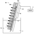
- the water absorbing material 50 and the heat transfer body 52 are formed in a plate-like body and are disposed in a state where the water absorbing material 50 is laminated on the front surface side of the heat transfer body 52, and the water absorbing material 50 is obliquely upward.
- the heat transfer body 52 is provided so as to be disposed.
- FIGS. 1-9 the location used as the principal part of the humidifier 1 is illustrated, and illustration of case 8 grade
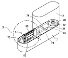
- the humidifier 1 includes a lid 2, a water supply tank 3, a steam cover 4, a steam generator 5, a water level detection means 6, a water tank 7, and a case 8. ing.
- the water supply tank 3 and the steam cover 4 are configured so as to be integrally assembled above the water tank 7, and these are stored in the case 8 in an integrated state.
- the lid 2 is a flat plate formed so as to close the upper surface of the case 8, and the lid 2 is formed with a plurality of outlets 20, and steam (water vapor) generated from the steam generator 5. However, it blows out from the blower outlet 20 through the opening part 40 formed in the steam cover 4.
- the humidifier 1 includes an operation display unit (not shown), and includes an operation switch that can turn on and off the heating unit 53, a display unit that displays an on / off state of the operation switch, and the like. is doing.
- the operation switch is turned on, the heating means 53 is driven to start the humidifying operation, and when the operation switch is turned off, the driving of the heating means 53 is stopped and the humidifying operation is stopped.
- the case 8 includes a front plate 80 provided on the front surface, the water supply tank 3 integrated as described above, and a box-shaped accommodation portion 81 in which the steam cover 4 and the water storage tank 7 are accommodated.
- the shape of the case 8 is not limited to the illustrated example, but the illustrated example is formed in a concave shape on the front side of the panel (humidity adjusting panel) 10 having the humidity control function shown in FIGS. It is formed thin so that it can be stored in the receiving recess 11.
- a front plate 80 that is gently curved is provided on the front surface of the case 8, and in the vicinity of the left and right end portions of the front plate 80, a handle portion 80 a that is formed in a concave shape is formed.
- a rear surface of the front plate 80 is provided with an accommodating portion 81 having an open top surface and a substantially rectangular parallelepiped shape.
- the water supply tank 3 includes a water supply tank main body 33 made of an oval shaped housing in plan view, a water injection port 30 that serves as a water spout, and a cap 31 that seals the water injection port 30.
- the water storage tank 7 is composed of an oval frame in plan view, and includes a water reservoir 70 into which the water-absorbing material 50 is immersed, a connecting portion 71 to which the water supply tank 3 is connected, and water from the water supply tank 3 to the water reservoir 70. And a pedestal portion 74 in which the water supply tank 3 is installed.
- the water storage tank 7 is provided with a water reservoir 70 on one side, a connecting part 71 on the other side, and a flow path 73 so as to connect between the water reservoir 70 and the connecting part 71.
- a water absorbing material 50 is immersed in the water reservoir 70, and the water absorbing material 50 is disposed obliquely upward. Therefore, the water reservoir 70 is disposed at the rear position of the front plate 80 so that the steam is efficiently blown forward from the outlet 20.
- an attachment base portion 73 to which a holder 51 for locking the water absorbing material 50 is attached and fixed is provided behind the water reservoir portion 70.
- the water supply tank 3 is configured to be detachably attached to a connecting portion 71 provided in the water tank 7.
- the water supply tank 3 is configured to be portable so that it can be removed from the connecting portion 71 of the water storage tank 7 and carried to a place where there is a faucet.
- An open water injection port 30 is formed on the lower surface side of the water supply tank 3, and when supplying tap water, the cap 31 is removed by turning the water supply tank 3 upside down, and water is supplied from the water injection port 30.
- the water injection port 30 is sealed with a cap 31, and the cap 31 is provided with a valve portion 32 having a valve function.
- the connecting portion 71 is provided with a protruding valve contact portion 72, and the valve portion 32 is configured such that when the valve contact portion 72 contacts the valve seat 72, a valve seat (not shown) is opened. Has been.
- valve portion 32 when the water supply tank 3 is carried, the valve portion 32 is in a closed state. When the valve portion 32 is in contact with and connected to the valve contact portion 72, the valve portion 32 is opened.
- the shapes of the water supply tank 3 and the water tank 7 are not limited to the illustrated examples.
- the water tank 7 is provided with a water level detection means 6 for detecting the water level of the water tank 7.
- the configuration of the water level detection means 6 is not particularly limited, and may be configured to detect the water level of the water supply tank 3 or may detect the water level of the water reservoir 70. In short, any material that can detect that the water-absorbing material 50 has insufficient water to absorb water may be used.
- the water level detecting means 6 is provided on the lower surface side of the water supply tank 3 connected to the water storage tank 7 and in the vicinity of the water reservoir 70 and the flow path 73.
- a steam generating unit 5 is provided above the water reservoir 70 of the water storage tank 7, and a steam cover 4 is provided so as to cover the steam generating unit 5.
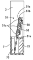
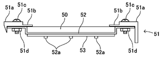
- the steam generating unit 5 includes a water absorbing material 50, a holder 51 that locks the water absorbing material 50, a heat transfer body 52, and a heating means 53.
- the water absorbing material 50 is formed in a vertically long, substantially rectangular plate shape so that it can be disposed in a state where it is immersed in water stored in the water reservoir 70 and laminated on the front side of the heat transfer body 52 (see FIG. 3). ), The size of the water absorbing material 50 is formed so as to be accommodated in a recess 52c of the heat transfer body 52, which will be described later, and to be provided with a portion where the lower portion of the water reservoir 70 is immersed.
- the water-absorbing material 50 has a two-layer structure, and is laminated on the water-absorbing layer 50a and a water-absorbing layer 50a made of a water-absorbing material provided in contact with the heat transfer body 52 as described above. And an impurity trapping layer 50b for trapping impurities contained in water.
- the water absorption layer 50a disposed in close contact with the heat transfer body 52 is a lower layer, and the impurity trapping layer 50b is laminated on the upper layer of the water absorption layer 50a.
- the material for forming the water absorption layer 50a is not particularly limited as long as it is made of a water-absorbing material with good water absorption efficiency, can absorb the water in the water reservoir 70 and can withstand the heat transmitted from the heat transfer body 52. is not. That is, the water absorption layer 50a may be any material that sucks up water stored in the water reservoir 70 by capillary action.
- a fabric made of polyester fiber, polypropylene fiber, rayon fiber, cotton or the like, a knitted fabric, or a nonwoven fabric is used as the water absorption layer 50a.
- a composite polyester fiber board is desirably used as the absorbent layer 50a.
- the composite polyester fiber board is formed using, for example, a hard porous body made of polyester fiber.
- “Unibex SB (registered trademark)” manufactured by Unitika Ltd. is used for the hard porous body made of polyester fiber.
- the water absorption speed can be improved by the water absorption layer 50a.
- the composite polyester fiber board has shape retention and can be made a relatively hard fiber board. Even when a material that generates water is used, the water supply layer 50a regulates the elongation of the water absorbing material 50, so that the elongation of the water absorbing material 50 can be suppressed.
- the water absorbing material 50 is disposed in a state of being laminated on the front side of the heat transfer body 52, and the heat transfer body 52 is inclined so that the water absorbing material 50 is disposed obliquely upward. It is desirable to be provided. According to this, since the water absorbing material 50 can be disposed in close contact with the front surface of the heat transfer body 52 by utilizing its own weight as described later, the water absorbing material 50 with less elongation is arranged. Synergistic effects of the installation can further enhance the adhesion between the water-absorbing material 50 and the heat transfer body 52, and can withstand long-term use without reducing the humidification ability.
- the material for forming the impurity trapping layer 50b is not particularly limited as long as impurities contained in water can be attached and trapped.
- a rayon fiber board produced by a needle punch manufacturing method is preferably used. It is done.
- the impurity trapping layer 50b is produced by stacking a plurality of rayon fiber sheets in the thickness direction and bonding them together by needle punching.
- the impurity trapping layer 50b may be a cotton fiber sheet.
- the impurities trapping in the water can be reliably trapped by the impurity trapping layer 50b.
- the lamination method of the water absorption layer 50a and the impurity trapping layer 50b is not particularly limited as long as it is superposed so that water absorption and impurity adhesion can be maintained.
- the four circumferences may be laminated or integrated by bonding or sewing.
- the holder 51 is provided in a substantially upright state with respect to the mounting base portion 73.
- the holder 51 is formed so as to hold both sides of the heat transfer body 52 and holds the heat transfer body 52 in an inclined state, and the water absorbing material 50 is in close contact with the front surface of the heat transfer body 52.
- a locking portion 51b to be locked and a fixing portion 51e fixed to the mounting base portion 73 are provided.
- the holding part 51a is provided in an obliquely standing state, and a plurality of through holes are formed in the vertical direction in order to fix and hold the left and right side parts 52d and 52d of the heat transfer body 52.
- the illustrated example shows a state in which the fixing tool 51c is inserted into the through hole, and the heat transfer body 52 is fixed and held by the fixing tool 51c.
- the inclination angle ⁇ of the holding portion 51a is not particularly limited.
- the holding portion 51a is inclined so as to have an acute angle (preferably 65 ° to 85 °) with respect to the horizontal plane (the mounting base portion 73 and the fixing portion 51e). It is desirable that When the water storage tank 7 is disposed on a plane parallel to the horizontal plane, the upper surface of the attachment base 73 and the upper surface of the fixing portion 51e are parallel to the horizontal plane.
- the inclination angle ⁇ is equal to the angle between the normal vector of one surface (front surface) of the heat transfer plate 52 and the normal vector of the horizontal plane when the water tank (water storage tank) 7 is arranged on a plane parallel to the horizontal plane. . Therefore, in the heat transfer plate 52, when the water tank 7 is arranged on a plane parallel to the horizontal plane, the angle between the normal vector of the horizontal plane and the normal vector of one surface (front surface) of the heat transfer plate 52 is an acute angle.
- the water tank 7 is attached.
- the heat transfer plate 52 is placed in the water tank 7 so that the angle between the normal vector of the surface of water in the water tank 7 and the normal vector of one surface (front surface) of the heat transfer plate 52 is an acute angle. It is attached.
- the water absorbing material 50 is not in close contact with the heat transfer body 52 using a separate member, but is in close contact with the heat transfer body 52 using its own weight.
- the adhesion of the heat transfer body 52 does not deteriorate. Therefore, efficient humidification can be performed over a long period of time, and a decrease in the humidifying ability of the humidifier 1 can be prevented.
- the planar installation space of the holder 51 is widened, so that it is difficult to make the humidifier 1 thin.
- the inclination angle of the holding portion 51a is 85 degrees ⁇ 90 degrees, the humidifier 1 can be thinned, but the water absorbing material 50 is placed on the front surface of the heat transfer body 52 by utilizing the weight of the water absorbing material 50. It becomes difficult to dispose the water absorbent material in close contact, and the water absorbing material 50 may slip off.
- the water absorbing material 50 cannot be disposed obliquely upward, and the water absorbing material 50 is brought into close contact with the front surface of the heat transfer body 52 by utilizing the weight of the water absorbing material 50. It becomes impossible to arrange by.
- the locking portion 51b is formed so as to further extend in the opposing direction from the opposing ends of the holding portions 51a provided on both sides of the heat transfer body 52.
- the water absorbing material 50 can be disposed so as to press the upper sides of the left and right ends of the water absorbing material 50 in the direction of the heat transfer body 52 without falling forward.
- the fixing portion 51e is formed with a plurality of through holes so that the fixing portion 51e is mounted on the mounting base portion 73. In the illustrated example, the fixing portion 51e is fixed to the mounting base portion 73. The state fixed by the tool 51f is shown.
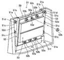
- the heat transfer body 52 is provided in order to efficiently transmit the heat generated by the heating means 53 to the water absorbing material 50, and is made of aluminum, aluminum alloy, or the like having good thermal conductivity, and is formed in a substantially rectangular plate shape.
- a recess 52c for holding the water absorbing material 50 is formed on the front side of the heat transfer body 52. Since the left and right side portions 52d of the heat transfer body 52 are fixed to the holding portion 51a, the recess 52c is formed in a shape that is recessed from the both side portions 52d, 52d in a step shape toward the back surface.
- the heat transfer body 52 is held above the heat transfer body 52 in the state where the heat transfer body 52 is held by the holder 51.
- the side, the lower side, and the front side are open spaces, and the water absorbing material 50 is inserted from the upper side. When the water absorbing material 50 is replaced, it can be removed so as to be extracted from the upper side.
- the water absorbing material 50 itself is not fixed to the holder 51 or the heat transfer body 52 with a fixture or the like. Therefore, for example, the water absorbing material 50 can be easily replaced or removed.
- the holding power of the water absorbing material 50 with the heat transfer body 52 can be further increased.
- the humidification efficiency can be improved.
- the water absorbing material 50 is not structured to be fixed and held on the heat transfer body 52 with any fixing tool as described above, the water absorbing material 50 to which weight is applied by sucking water is inclined from the heat transfer body 52 inclined. In order to improve retention so as not to slip down, the front side of the heat transfer body 52 may be surface-treated.
- Through holes 52d and 52d are formed in both side portions 52d and 52d of the heat transfer body 52 in correspondence with the through holes formed in the holding portion 51a, and the fixture 51c is inserted through the through holes (FIG. 6, FIG. 6). 7). And the nut (fastener) 51d is attached to the axial part of the fixing tool 51c, and the heat transfer body 52 is firmly held by the holding part 51a.
- a plurality of cylindrical protrusions 52a are formed so as to protrude in the back direction.
- the protrusions 52a may be formed integrally with the heat transfer body 52, or may be attached separately formed.
- the peripheral surface of the protrusion 52a may be formed with a thread groove so that a fastener (nut) 52b is attached as shown in the figure. That is, the protrusion 52a may be a bolt corresponding to the nut 52b.
- the heating means 53 is not particularly limited as long as it can heat the water absorbing material 50 via the heat transfer body 52 and generate steam, and is preferably formed in a plate shape.
- a planar heater such as a PTC heater using a characteristic of PTC (Positive Temperature Coefficient) can be used.
- a plurality of through holes 53a are formed corresponding to the protrusions 52a.
- the protrusion 52a is inserted into the through holes 53a formed in the upper and lower ends of the heating means 53, and tightened with a fastener (nut) 52b, so that the heating means 53 is placed on the back side of the heat transfer body 52.
- nut fastener
- the humidifier 1 includes a control unit 9 as shown in FIG.
- the controller 9 is configured to control the heating means 53 to heat the water held by the water absorption plate 50 via the heat transfer plate 52 to generate water vapor.
- the control unit 9 is configured to apply a predetermined DC voltage to the heating unit 53 based on, for example, electric power obtained from a commercial AC power source.
- the controller 9 causes the heating unit 53 to generate heat by applying a predetermined DC voltage to the heating unit 53.
- the heat generated by the heating means 53 is transmitted to the water absorption plate 50 by the heat transfer plate 52, and as a result, water held in the water absorption plate 50 (water absorption layer 50a) evaporates to generate water vapor.
- the control unit 9 applies the predetermined DC voltage to the heating unit 53 to generate steam. That is, the humidifying operation is started.
- the controller 9 stops applying the predetermined DC voltage to the heating means 53 when the operation switch of the operation display unit is turned off. That is, the humidifying operation is stopped.
- Such a control unit 9 is configured using a microcomputer, a rectifier circuit, an AC / DC converter, a DC / DC converter, or the like.
- the method of attaching and fixing the heat transfer body 52 and the heating means 53 is not limited to the illustrated example.
- the protrusion 52a may be caulked after the protrusion 52a is inserted into the through hole 53a.
- an adhesive may be applied and fixed to the peripheral surface of the protrusion 52a.
- the protrusion 52a may be fixed by welding.
- the heating means 53 can be attached and detached. If so, it can be removed for maintenance.
- the lower part of the water absorbing material 50 is immersed in the water stored in the water reservoir 70, and water is first absorbed into the impurity trapping layer 50b disposed in the upper layer (see the dotted arrow in FIG. 1). At this time, since impurities contained in the water adhere to and are trapped on the impurity trapping layer 50b, it is possible to prevent impurities from entering the water absorbing layer 50a disposed in the lower layer, and the water absorbing layer 50a absorbs water. Can be maintained over a long period of time. The water in the water reservoir 70 is sucked upward by capillary action to the water absorption layer 50a or directly from the water absorption layer 50a via the impurity trapping layer 50b.
- the heating means 53 When the heating means 53 is driven in this state, the water absorbing material 50 is heated via the heat transfer body 52 disposed on the upper back side of the water absorbing material 5, and the water is heated to become steam (see the thick arrow in FIG. 1). ).
- the steam generated by the steam generating unit 5 is blown out from the outlet 20 through the opening 40 and can be humidified around the humidifier 1.
- the humidifier 1 includes a water absorbing material (water absorbing plate) 50 that absorbs water stored in the water tank 7, and a heat transfer body in which the water absorbing material 50 is disposed on the front side. 52 and a heating means 53 disposed on the back side of the heat transfer body 52, the water absorbing material 50 is provided in contact with the heat transfer body 52 and is made of a water absorbing material 50a made of a water absorbing material. And an impurity trapping layer 50b that is stacked on the water absorbing layer 50a and traps impurities contained in water.
- a water absorbing material water absorbing plate
- the humidifier 1 of the present embodiment includes a water tank (water storage tank) 7, a heat transfer plate 52, a water absorption plate (water absorption material) 50, a heating unit 53, and a control unit 9.
- the water tank 7 is configured to store water.
- the heat transfer plate 52 is formed in a plate shape from a material having thermal conductivity, and is attached to the water storage tank 7.
- the water absorption plate 50 is arranged on one surface (front surface) of the heat transfer plate 52 and is configured to absorb and hold water stored in the water storage tank 7.
- the heating means 53 is disposed on the other surface (rear surface) of the heat transfer plate 52.
- the controller 9 is configured to control the heating means 53 to heat the water held by the water absorption plate 50 via the heat transfer plate 52 to generate water vapor.
- the water absorption plate 50 includes an impurity trapping layer 50b and a water absorption layer 50a.
- the impurity trapping layer 50b is configured to absorb water stored in the water tank 7 and remove impurities from the absorbed water.
- the water absorption layer 50a is configured to absorb and retain water from which impurities have been removed by the impurity trapping layer 50b.
- the humidifier 1 of Embodiment 1 since impurities contained in water adhere to and are trapped in the impurity trapping layer 50b, it is possible to prevent impurities from entering the water absorbing layer 50a disposed in the lower layer.
- the water absorption by the water absorption layer 50a can be maintained over a long period of time. Therefore, the humidification ability can be improved.
- the impurity trapping layer 50b is disposed on one surface (front surface) of the water absorption layer 50a.
- the other surface (rear surface) of the water absorption layer 50b is in contact with one surface (front surface) of the heat transfer plate 52.
- the water absorption layer 50a is a board formed using a composite polyester fiber. That is, the water absorption layer 50a is a composite polyester fiber board.
- the water absorption speed can be improved by the water absorption layer 50a.
- the contact force with the heat source block is weakened and the humidification ability is reduced. May be incurred.
- the composite polyester fiber board has shape retention and can be a relatively hard fiber board, even if a material that slightly expands due to water absorption is used as the impurity capturing layer 50b, the water supply layer 50a. However, the elongation of the water absorbing material 50 can be suppressed.
- the impurity trapping layer 50b is a rayon fiber board produced by a needle punch manufacturing method.
- the impurity supplementary layer 50b is a board formed using rayon fibers.
- impurities floating in water can be reliably trapped by the impurity trapping layer 50b.
- the impurity trapping layer 50b is formed using, for example, a needle punch manufacturing method.
- the impurity trapping layer 50b can be easily formed.
- the reference 1 discloses a humidifier that employs the above-described method.
- a water-absorbing element having a water-absorbing material that sucks up water in a reservoir tank by capillary action on a truncated cone-shaped heat source block.
- a humidifier fitted with is described.
- both side edges of the water absorbing material having a fan-shaped shape in which the truncated cone is developed are rubberized. It is connected with the elastic body.
- the humidifier can prevent a decrease in humidification capacity over a long period of time.
- the humidifier 1 includes a water absorbing material 50 that absorbs water stored in the water tank 7, a heat transfer body 52 that transfers heat to the water absorbing material 50, and a back side of the heat transfer body 52.
- the water absorbing material 50 and the heat transfer body 52 are formed in a plate-like body, and the water absorption material 50 is laminated on the front side of the heat transfer body 52.
- the heat transfer body 52 is inclined and provided so that the water absorbing material 50 is disposed obliquely upward.
- the heat transfer plate 52 is an angle between the normal vector of the water surface in the water tank 7 and the normal vector of one surface (front surface) of the heat transfer plate 52 (front surface). It is attached to the water tank 7 so that the inclination angle ⁇ ) becomes an acute angle.
- the water absorbing material 50 can be disposed in close contact with the front surface of the heat transfer body 52 using the weight of the water absorbing material 50.
- the water absorbing material 50 is not in close contact with the heat transfer body 52 using a separate member, but is in close contact with the heat transfer body 52 using its own weight.
- the adhesion of the heat transfer body 52 does not deteriorate. Therefore, efficient humidification can be performed over a long period of time, and a decrease in the humidifying ability of the humidifier 1 can be prevented.
- a plurality of protrusions 52 a are formed on the back side of the heat transfer body 52, and a plurality of through holes 53 a are formed in the plate-like heating means 53.
- the protrusion 52a is inserted into the through hole 53a, and the heating means 53 is held on the back surface of the heat transfer body 53 by the fastener 52b.
- the humidifier 1 of this embodiment includes a fastener (nut) 52b that fixes the heating means 53 to the heat transfer body 52.
- a protrusion 52 a is formed on the other surface (rear surface) of the heat transfer body 52.
- the heating means 53 is formed in a plate shape and has a through hole 53a through which the protrusion 52a passes.
- the heating means 53 is disposed on the other surface (rear surface) of the heat transfer plate 52 so that the protrusion 52a passes through the through hole 53a.
- the fastener 52b is attached to the tip of the protrusion 52a that has passed through the through hole 53a so that the heating means 53 is in close contact with the other surface (rear surface) of the heat transfer body 52.
- the heating means 53 can be firmly attached and fixed in a state where the heating means 53 is in close contact with the back side of the heat transfer body 52. Moreover, according to this, since the connection member for fixing the heat-transfer body 52 and the heating means 53 separately in close contact is not required, the number of parts can be reduced.
- a recess 52c is formed on the front side of the heat transfer body 52 to hold the water absorbing material 50 in a accommodated state.
- a recess 52c that accommodates the water absorbing plate 50 is formed on one surface (front surface) of the heat transfer body 52.
- the water absorbing material 50 itself is not fixed to the holder 51 or the heat transfer body 52 with a fixture or the like. Therefore, for example, the water absorbing material 50 can be easily replaced or removed. Further, if the water absorbing material 50 is held in the recess 52c formed on the front surface side of the heat transfer body 52 in this way, the holding power of the water absorbing material 50 with the heat transfer body 52 can be further increased. The humidification efficiency can be improved.
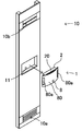
- the humidifier 1 can be thinned as described above, it can be incorporated into a thin plate-like panel 10 having a humidity control function, for example.
- the panel 10 shown in FIGS. 8 and 9 is installed substantially vertically along a wall surface (not shown).
- the panel 10 includes an exhaust port 10b formed on the upper side, an intake port 10a formed on the lower side, and a functional unit (not shown) that contains a functional material such as a humidity control material or a deodorizing agent.
- the panel 10 is configured to take in the air sucked from the air inlet 10a into the functional part, perform humidity adjustment and deodorization, and then exhaust the air conditioned after being exhausted from the air outlet 10b.
- a substantially rectangular housing recess 11 (see FIG. 9) is formed at the front center of the panel 10, and the humidifier 1 is incorporated into the housing recess 11 for use.
- the humidifier 1 can be easily removed by grasping the handles 80a, 80a and pulling forward. According to this, if the humidifier 1 is removed and the cover body 2 is removed, the water supply tank 3 can also be easily removed, and the water injection operation can be easily performed.
- the shape of the humidifier 1 and each member which comprises this, a structure, etc. are not limited to the example of a figure.
- the example which is not provided with the air blower which blows the humidified air here is shown, it is good also as what was provided.
- the installation example of the humidifier 1 is not limited to FIGS. 8 and 9, and may be used by being embedded directly in a wall surface, or the humidifier 1 may be used alone at a favorite place. Needless to say, you can.
Abstract
A humidifier is equipped with a water tank, a heat transfer plate, a water-absorbing plate, a heating means, and a control unit. The water tank is constructed so as to accumulate water. The heat transfer plate is formed as a plate from a heat-conducting material, and is attached to the water tank. The water-absorbing plate is arranged on one face of the heat transfer plate, and is constructed so as to absorb and retain water accumulated in the water tank. The heating means is arranged on the other face of the heat-transfer plate. The control unit is constructed so as to control the heating means to heat, through the heat transfer plate, the water retained on the water-absorbing plate, thus generating water vapor. The water-absorbing plate has an impurity-trapping layer and a water-absorbing layer. The impurity-trapping layer is constructed so as to absorb the water accumulated in the water tank and remove impurities from the absorbed water. The water-absorbing layer is constructed so as to absorb and retain the water from which the impurities have been removed by the impurity-trapping layer.
Description
本発明は、室内等を加湿する加湿器に関する。
The present invention relates to a humidifier that humidifies a room or the like.
従来より、水を加熱手段によって加熱して蒸発させ、室内等を加湿する加湿器が知られている。種々ある加湿器の中でも、水槽内に溜めた水道水を吸水板(吸水材)で吸水し加熱して水を蒸発させ加湿する方式を採用したものがある。
Conventionally, humidifiers are known that heat and evaporate water by a heating means to humidify a room or the like. Among various humidifiers, there is one that employs a method in which tap water stored in a water tank is absorbed by a water absorbing plate (water absorbing material) and heated to evaporate the water and humidify it.
このような加湿器の場合、水道水中の不純物(不揮発成分の炭酸カルシウム、硫酸マグネシウム、硫酸カルシウム等)が析出し、これがスケールとなって吸水材に固着し、このため、吸水材の吸水性が低下し、これが加湿器の加湿能力の低下を招く点等が問題となる。
In the case of such a humidifier, impurities in the tap water (non-volatile components such as calcium carbonate, magnesium sulfate, calcium sulfate, etc.) are deposited, which becomes a scale and adheres to the water-absorbing material. This causes a problem, for example, that this causes a decrease in the humidifying capacity of the humidifier.
文献1(日本国特許第3769676号公報)には、上述の方式を採用した加湿器が開示されており、吸水材としては、レーヨン繊維とポリエステル繊維とを混合したニードルパンチ不織布が用いられている。
Reference 1 (Japanese Patent No. 3769676) discloses a humidifier employing the above-described method, and a needle punched nonwoven fabric in which rayon fibers and polyester fibers are mixed is used as a water absorbing material. .
そこで長期の使用に耐えることができ、また吸水性能と不純物を除去する性能を備えた吸水材が求められている。
Therefore, there is a demand for a water-absorbing material that can withstand long-term use and has water-absorbing performance and the ability to remove impurities.
本発明は、上記実情に鑑みてなされたものであり、加湿能力の向上を図ることができる加湿器を提供することを目的としている。
This invention is made | formed in view of the said situation, and it aims at providing the humidifier which can aim at the improvement of a humidification capability.
本発明に係る加湿器の第1の形態は、水槽と、伝熱板と、吸水板と、加熱手段と、制御部と、を備える。前記水槽は、水を溜めるように構成される。前記伝熱板は、熱伝導性を有する材料により板状に形成され、前記水槽に取り付けられる。前記吸水板は、前記伝熱板の一面に配置され、前記水槽に溜められた水を吸収して保持するように構成される。前記加熱手段は、前記伝熱板の他面に配置される。前記制御部は、前記加熱手段を制御して、前記伝熱板を介して前記吸水板に保持された水を加熱して水蒸気を発生させるように構成される。前記吸水板は、不純物捕捉層と、吸水層と、を有する。前記不純物捕捉層は、前記水槽に溜められた水を吸収して、吸収した水から不純物を除去するように構成される。前記吸水層は、前記不純物捕捉層により不純物が除去された水を吸収して保持するように構成される。
A first form of a humidifier according to the present invention includes a water tank, a heat transfer plate, a water absorption plate, a heating means, and a control unit. The water tank is configured to store water. The heat transfer plate is formed in a plate shape from a material having thermal conductivity, and is attached to the water tank. The water absorbing plate is disposed on one surface of the heat transfer plate and is configured to absorb and hold water stored in the water tank. The heating means is disposed on the other surface of the heat transfer plate. The control unit is configured to control the heating unit to heat water held on the water absorption plate via the heat transfer plate to generate water vapor. The water absorbing plate has an impurity trapping layer and a water absorbing layer. The impurity trapping layer is configured to absorb water stored in the water tank and remove impurities from the absorbed water. The water absorption layer is configured to absorb and retain water from which impurities have been removed by the impurity trapping layer.
本発明に係る加湿器の第2の形態は、第1の形態において、前記不純物捕捉層は、前記吸水層の一面に配置される。前記吸水層の他面は前記伝熱板の前記一面に接触している。
In the second embodiment of the humidifier according to the present invention, the impurity trapping layer is disposed on one surface of the water absorption layer in the first embodiment. The other surface of the water absorption layer is in contact with the one surface of the heat transfer plate.
本発明に係る加湿器の第3の形態は、第1または第2の形態において、前記吸水層は、複合ポリエステル繊維を用いて形成されたボードである。
A third form of the humidifier according to the present invention is a board in which the water absorption layer is formed using a composite polyester fiber in the first or second form.
本発明に係る加湿器の第4の形態は、第1~第3のうちいずれか1つにおいて、前記不純物補足層は、レーヨン繊維を用いて形成されたボードである。
A fourth aspect of the humidifier according to the present invention is a board in which the impurity supplemental layer is formed using rayon fibers in any one of the first to third.
本発明に係る加湿器の第5の形態は、第4の形態において、前記不純物捕捉層は、ニードルパンチ製法を利用して形成される。
In a fifth aspect of the humidifier according to the present invention, in the fourth aspect, the impurity trapping layer is formed using a needle punch manufacturing method.
本発明に係る加湿器の第6の形態は、第1~第5の形態のうちいずれか1つにおいて、前記伝熱板は、前記水槽内の水の表面の法線ベクトルと前記伝熱板の前記一面の法線ベクトルとの間の角度が鋭角となるように、前記水槽に取り付けられている。
A humidifier according to a sixth aspect of the present invention is the humidifier according to any one of the first to fifth aspects, wherein the heat transfer plate includes a normal vector of a surface of water in the water tank and the heat transfer plate. Are attached to the water tank so that the angle between the normal vector and the normal vector is an acute angle.
本発明に係る加湿器の第7の形態は、第1~第6の形態のうちいずれか1つにおいて、前記加熱手段を前記伝熱体に固定する締結具を備える。前記伝熱体の前記他面には、突起部が形成される。前記加熱手段は、板状に形成され、前記突起部を通す貫通孔を有し、前記突起部が前記貫通孔を通るようにして前記伝熱板の前記他面に配置される。前記締結具は、前記加熱手段が前記伝熱体の前記他面に密着するように、前記貫通孔を通った前記突起部の先端に取り付けられる。
A seventh aspect of the humidifier according to the present invention includes a fastener for fixing the heating means to the heat transfer body in any one of the first to sixth aspects. A protrusion is formed on the other surface of the heat transfer body. The heating means is formed in a plate shape, has a through hole through which the protrusion is passed, and is disposed on the other surface of the heat transfer plate so that the protrusion passes through the through hole. The said fastener is attached to the front-end | tip of the said projection part which passed through the said through-hole so that the said heating means closely_contact | adheres to the said other surface of the said heat exchanger.
本発明に係る加湿器の第8の形態は、第1~第7の形態のうちいずれか1つにおいて、前記伝熱体の一面には、前記吸水板を収容する凹所が形成されている。
According to an eighth aspect of the humidifier of the present invention, in any one of the first to seventh aspects, a recess for accommodating the water absorbing plate is formed on one surface of the heat transfer body. .
以下に本発明の一実施形態の加湿器1について、図1-9を参照しながら説明する。
Hereinafter, a humidifier 1 according to an embodiment of the present invention will be described with reference to FIGS. 1-9.
本実施形態に係る加湿器1は、水槽(以下、貯水槽7という)に溜められた水を吸水する吸水材50と、この吸水材50が前面側に配設された伝熱体52と、この伝熱体52の背面側に配設された加熱手段53とを備えている。
The humidifier 1 according to this embodiment includes a water absorbing material 50 that absorbs water stored in a water tank (hereinafter referred to as the water storage tank 7), a heat transfer body 52 in which the water absorbing material 50 is disposed on the front side, Heating means 53 disposed on the back side of the heat transfer body 52 is provided.
ここで、吸水材50は、伝熱体52に接触して設けられ吸水性材料からなる吸水層50aと、この吸水層50aに積層され前記水に含まれる不純物を捕捉する不純物捕捉層50bとを有している。
Here, the water-absorbing material 50 includes a water-absorbing layer 50a made of a water-absorbing material provided in contact with the heat transfer body 52, and an impurity trapping layer 50b that is stacked on the water-absorbing layer 50a and traps impurities contained in the water. Have.
また、吸水材50及び伝熱体52は、板状体に形成され、伝熱体52の前面側に吸水材50が積層された状態で配設されているとともに、吸水材50が斜め上向きに配設されるよう伝熱体52が傾斜して設けられている。
Further, the water absorbing material 50 and the heat transfer body 52 are formed in a plate-like body and are disposed in a state where the water absorbing material 50 is laminated on the front surface side of the heat transfer body 52, and the water absorbing material 50 is obliquely upward. The heat transfer body 52 is provided so as to be disposed.
以下、本実施形態の加湿器1を詳しく説明する。
Hereinafter, the humidifier 1 of this embodiment will be described in detail.
なお、図1~図9では、加湿器1の要部となる箇所を図示し、ケース8等の図示は省略している。
In addition, in FIGS. 1-9, the location used as the principal part of the humidifier 1 is illustrated, and illustration of case 8 grade | etc., Is abbreviate | omitted.
加湿器1は、図1,2に示すように蓋体2と、給水タンク3と、蒸気カバー4と、蒸気発生部5と、水位検知手段6と、貯水槽7と、ケース8とを備えている。
As shown in FIGS. 1 and 2, the humidifier 1 includes a lid 2, a water supply tank 3, a steam cover 4, a steam generator 5, a water level detection means 6, a water tank 7, and a case 8. ing.
給水タンク3及び蒸気カバー4は、貯水槽7の上方に一体に組み付けられるように構成されており、これらは一体にした状態でケース8内に納められる。
The water supply tank 3 and the steam cover 4 are configured so as to be integrally assembled above the water tank 7, and these are stored in the case 8 in an integrated state.
蓋体2は、ケース8の上面を塞ぐように形成された平板状体からなり、蓋体2には、複数の吹出口20が形成されており、蒸気発生部5から発生した蒸気(水蒸気)が、蒸気カバー4に形成された開口部40を通じて吹出口20から吹き出すようになっている。
The lid 2 is a flat plate formed so as to close the upper surface of the case 8, and the lid 2 is formed with a plurality of outlets 20, and steam (water vapor) generated from the steam generator 5. However, it blows out from the blower outlet 20 through the opening part 40 formed in the steam cover 4.
なお、加湿器1は、ここには示していないが、操作表示部(不図示)を備えており、加熱手段53のオンオフが行える操作スイッチや操作スイッチのオンオフ状態を表示する表示部等を有している。操作スイッチがオンになると加熱手段53が駆動し加湿動作を開始し、操作スイッチがオフになると加熱手段53の駆動が停止し加湿動作が停止となる。
Although not shown here, the humidifier 1 includes an operation display unit (not shown), and includes an operation switch that can turn on and off the heating unit 53, a display unit that displays an on / off state of the operation switch, and the like. is doing. When the operation switch is turned on, the heating means 53 is driven to start the humidifying operation, and when the operation switch is turned off, the driving of the heating means 53 is stopped and the humidifying operation is stopped.
ケース8は、前面に設けられた前板80と、上述のように一体とされた給水タンク3と、蒸気カバー4及び貯水槽7が収容される箱状の収容部81とを備えている。ケース8の形状は、図例に限定されるものでないが、図例のものは、図8,9に示す調湿機能等を備えたパネル(調湿パネル)10の前面側に凹状に形成された収容凹所11に収納できるように薄型に形成されている。ケース8の前面は、緩やかに湾曲した前板80が設けられており、前板80の左右の端部近傍には、凹状に窪んで形成された取手部80aが形成されている。前板80の背面には、上面が開口され略直方体形状の収容部81が設けられている。
The case 8 includes a front plate 80 provided on the front surface, the water supply tank 3 integrated as described above, and a box-shaped accommodation portion 81 in which the steam cover 4 and the water storage tank 7 are accommodated. The shape of the case 8 is not limited to the illustrated example, but the illustrated example is formed in a concave shape on the front side of the panel (humidity adjusting panel) 10 having the humidity control function shown in FIGS. It is formed thin so that it can be stored in the receiving recess 11. A front plate 80 that is gently curved is provided on the front surface of the case 8, and in the vicinity of the left and right end portions of the front plate 80, a handle portion 80 a that is formed in a concave shape is formed. A rear surface of the front plate 80 is provided with an accommodating portion 81 having an open top surface and a substantially rectangular parallelepiped shape.
給水タンク3は、平面視において長円形状の框体からなる給水タンク本体33と、水の注ぎ口となる注水口30と、注水口30を封止するキャップ31とを備えている。貯水槽7は、平面視において長円形状の框体からなり、吸水材50が浸される水溜部70と、給水タンク3が連結される連結部71と、給水タンク3の水を水溜部70へ流通させる流路73と、給水タンク3が設置される台座部74とを備えている。貯水槽7は、片側に水溜部70、他方片側に連結部71が設けられ、水溜部70と連結部71の間をつなぐように流路73が設けられている。水溜部70には、吸水材50が浸され、その吸水材50が斜め上向きに配設されている。そのため、吹出口20から前方向に効率よく蒸気が吹き出すように前板80の後方位置に水溜部70が配設される。そして図例のものは、この水溜部70の後方に吸水材50を係止するホルダー51が取り付け固定される取付基台部73が設けられている。
The water supply tank 3 includes a water supply tank main body 33 made of an oval shaped housing in plan view, a water injection port 30 that serves as a water spout, and a cap 31 that seals the water injection port 30. The water storage tank 7 is composed of an oval frame in plan view, and includes a water reservoir 70 into which the water-absorbing material 50 is immersed, a connecting portion 71 to which the water supply tank 3 is connected, and water from the water supply tank 3 to the water reservoir 70. And a pedestal portion 74 in which the water supply tank 3 is installed. The water storage tank 7 is provided with a water reservoir 70 on one side, a connecting part 71 on the other side, and a flow path 73 so as to connect between the water reservoir 70 and the connecting part 71. A water absorbing material 50 is immersed in the water reservoir 70, and the water absorbing material 50 is disposed obliquely upward. Therefore, the water reservoir 70 is disposed at the rear position of the front plate 80 so that the steam is efficiently blown forward from the outlet 20. In the illustrated example, an attachment base portion 73 to which a holder 51 for locking the water absorbing material 50 is attached and fixed is provided behind the water reservoir portion 70.
給水タンク3は、貯水槽7に設けられた連結部71に着脱自在に装着されるように構成されている。給水タンク3は、貯水槽7の連結部71から取り外して水道の蛇口がある場所まで持ち運びできるように可搬型に構成されている。給水タンク3の下面側には、開口した注水口30が形成されており、水道水を供給する際には、給水タンク3を上下逆にしてキャップ31を取り外し、注水口30から水を入れる。
The water supply tank 3 is configured to be detachably attached to a connecting portion 71 provided in the water tank 7. The water supply tank 3 is configured to be portable so that it can be removed from the connecting portion 71 of the water storage tank 7 and carried to a place where there is a faucet. An open water injection port 30 is formed on the lower surface side of the water supply tank 3, and when supplying tap water, the cap 31 is removed by turning the water supply tank 3 upside down, and water is supplied from the water injection port 30.
注水口30は、キャップ31で封止されており、キャップ31には、バルブ機能を有したバルブ部32が設けられている。連結部71と給水タンク3を連結するときには、図2に示すように給水タンク3のキャップ31側を下向きにした状態で連結する。連結部71には、突出して形成されたバルブ当接部72が設けられており、バルブ部32は、バルブ当接部72に当接すると弁座(不図示)が開状態になるように構成されている。
The water injection port 30 is sealed with a cap 31, and the cap 31 is provided with a valve portion 32 having a valve function. When connecting the connection part 71 and the water supply tank 3, it connects in the state which turned the cap 31 side of the water supply tank 3 downward as shown in FIG. The connecting portion 71 is provided with a protruding valve contact portion 72, and the valve portion 32 is configured such that when the valve contact portion 72 contacts the valve seat 72, a valve seat (not shown) is opened. Has been.
すなわち、バルブ部32は、給水タンク3を持ち運びする際には、閉状態になり、バルブ当接部72に当接して連結されると、バルブ部32が開状態になる。
That is, when the water supply tank 3 is carried, the valve portion 32 is in a closed state. When the valve portion 32 is in contact with and connected to the valve contact portion 72, the valve portion 32 is opened.
なお、給水タンク3、貯水槽7の形状等も図例に限定されるものではない。
The shapes of the water supply tank 3 and the water tank 7 are not limited to the illustrated examples.
貯水槽7には、貯水槽7の水の水位を検知するための水位検知手段6が設けられている。水位検知手段6の構成は特に限定されるものではなく、給水タンク3の水位を検知するように構成してもよいし、水溜部70の水位を検知するものとしてもよい。要は、吸水材50が吸水するための水が足りないことを検知できるものであればよい。図例のものは、水位検知手段6が、貯水槽7に連結された給水タンク3の下面側で且つ水溜部70及び流路73の近傍に設けられたものを示している。
The water tank 7 is provided with a water level detection means 6 for detecting the water level of the water tank 7. The configuration of the water level detection means 6 is not particularly limited, and may be configured to detect the water level of the water supply tank 3 or may detect the water level of the water reservoir 70. In short, any material that can detect that the water-absorbing material 50 has insufficient water to absorb water may be used. In the illustrated example, the water level detecting means 6 is provided on the lower surface side of the water supply tank 3 connected to the water storage tank 7 and in the vicinity of the water reservoir 70 and the flow path 73.
貯水槽7の水溜部70の上方には、蒸気発生部5が設けられ、蒸気発生部5を覆うように蒸気カバー4が設けられている。
A steam generating unit 5 is provided above the water reservoir 70 of the water storage tank 7, and a steam cover 4 is provided so as to cover the steam generating unit 5.
蒸気発生部5は、吸水材50と、吸水材50を係止するホルダー51と、伝熱体52と、加熱手段53とを備えている。
The steam generating unit 5 includes a water absorbing material 50, a holder 51 that locks the water absorbing material 50, a heat transfer body 52, and a heating means 53.
吸水材50は、水溜部70に溜められた水に浸され且つ伝熱体52の前面側に積層した状態で配設できるように縦長の略長方形の板状に形成されており(図3参照)、吸水材50の大きさは、後記する伝熱体52の凹所52c内に収容され且つ水溜部70にその下部が浸される部分が設けられるように形成される。
The water absorbing material 50 is formed in a vertically long, substantially rectangular plate shape so that it can be disposed in a state where it is immersed in water stored in the water reservoir 70 and laminated on the front side of the heat transfer body 52 (see FIG. 3). ), The size of the water absorbing material 50 is formed so as to be accommodated in a recess 52c of the heat transfer body 52, which will be described later, and to be provided with a portion where the lower portion of the water reservoir 70 is immersed.
図1に示すように吸水材50は、2層構造になっており、上述のように伝熱体52に接触して設けられ吸水性材料からなる吸水層50aと、この吸水層50aに積層され水に含まれる不純物を捕捉する不純物捕捉層50bとを有している。
As shown in FIG. 1, the water-absorbing material 50 has a two-layer structure, and is laminated on the water-absorbing layer 50a and a water-absorbing layer 50a made of a water-absorbing material provided in contact with the heat transfer body 52 as described above. And an impurity trapping layer 50b for trapping impurities contained in water.
すなわち、伝熱体52と密着した状態で配設される吸水層50aを下層とし、吸水層50aの上層に不純物捕捉層50bが積層されている。
That is, the water absorption layer 50a disposed in close contact with the heat transfer body 52 is a lower layer, and the impurity trapping layer 50b is laminated on the upper layer of the water absorption layer 50a.
吸水層50aを形成する素材は、吸水効率のよい吸水性材料からなり、水溜部70の水を吸い上げることができ、伝熱体52から伝わる熱に耐えられるものであれば、特に限定されるものではない。すなわち、吸水層50aは、水溜部70に溜められた水を毛細管作用によって吸い上げるものであればよい。例えば、吸水層50aとしては、ポリエステル繊維、ポリプロピレン繊維、レーヨン繊維、木綿等からなる織物、編物、不織布からなるものが用いられる。
The material for forming the water absorption layer 50a is not particularly limited as long as it is made of a water-absorbing material with good water absorption efficiency, can absorb the water in the water reservoir 70 and can withstand the heat transmitted from the heat transfer body 52. is not. That is, the water absorption layer 50a may be any material that sucks up water stored in the water reservoir 70 by capillary action. For example, as the water absorption layer 50a, a fabric made of polyester fiber, polypropylene fiber, rayon fiber, cotton or the like, a knitted fabric, or a nonwoven fabric is used.
吸収層50aは、例えば複合ポリエステル繊維ボードが望ましく用いられる。複合ポリエステル繊維ボードは、たとえば、ポリエステル繊維製の硬質多孔体を用いて形成される。好ましくは、ポリエステル繊維製の硬質多孔体には、ユニチカ株式会社製の「ユニベックスSB(登録商標)」が用いられる。
As the absorbent layer 50a, for example, a composite polyester fiber board is desirably used. The composite polyester fiber board is formed using, for example, a hard porous body made of polyester fiber. Preferably, “Unibex SB (registered trademark)” manufactured by Unitika Ltd. is used for the hard porous body made of polyester fiber.
これによれば、吸水層50aによって吸水スピードの向上を図ることができる。また吸水層50aとして複合ポリエステル繊維ボードを用いた場合、複合ポリエステル繊維ボードは保形性を備えており、比較的硬質な繊維ボードとすることができるので、不純物捕捉層50bとして、吸水により多少伸びが生じる素材が用いられても、給水層50aがその伸びを規制するため、吸水材50の伸びを抑えることができる。
According to this, the water absorption speed can be improved by the water absorption layer 50a. Further, when a composite polyester fiber board is used as the water absorption layer 50a, the composite polyester fiber board has shape retention and can be made a relatively hard fiber board. Even when a material that generates water is used, the water supply layer 50a regulates the elongation of the water absorbing material 50, so that the elongation of the water absorbing material 50 can be suppressed.
このように吸水材50の伸びを抑えることができれば、伝熱体52との密着性を維持できる。従って、図に示すように伝熱体52の前面側にこの吸水材50が積層された状態で配設されているとともに、吸水材50が斜め上向きに配設されるよう伝熱体52が傾斜して設けられているものが望ましい。これによれば、後記するように吸水材50の自重を利用して伝熱体52の前面に吸水材50を密着させた状態で配設することができるので、伸びの少ない吸水材50を配設することによる効果が相乗して、より一層、吸水材50と伝熱体52との密着性を高めることができ、加湿能力を低下させることなく長期の使用に耐えることができる。
If the elongation of the water absorbing material 50 can be suppressed in this way, the adhesion with the heat transfer body 52 can be maintained. Accordingly, as shown in the figure, the water absorbing material 50 is disposed in a state of being laminated on the front side of the heat transfer body 52, and the heat transfer body 52 is inclined so that the water absorbing material 50 is disposed obliquely upward. It is desirable to be provided. According to this, since the water absorbing material 50 can be disposed in close contact with the front surface of the heat transfer body 52 by utilizing its own weight as described later, the water absorbing material 50 with less elongation is arranged. Synergistic effects of the installation can further enhance the adhesion between the water-absorbing material 50 and the heat transfer body 52, and can withstand long-term use without reducing the humidification ability.
不純物捕捉層50bを形成する素材としては、水に含まれる不純物を付着させて捕捉できるものであれば、特に限定されるものではないが、例えばニードルパンチ製法によって作製されたレーヨン繊維ボードが望ましく用いられる。例えば、不純物捕捉層50bは、複数枚のレーヨン繊維製のシートを厚み方向に重ね、ニードルパンチにより一枚に結合することで作製される。なお、不純物捕捉層50bは、コットン繊維製のシートであってもよい。
The material for forming the impurity trapping layer 50b is not particularly limited as long as impurities contained in water can be attached and trapped. For example, a rayon fiber board produced by a needle punch manufacturing method is preferably used. It is done. For example, the impurity trapping layer 50b is produced by stacking a plurality of rayon fiber sheets in the thickness direction and bonding them together by needle punching. The impurity trapping layer 50b may be a cotton fiber sheet.
これによれば、不純物捕捉層50bによって水中を浮遊する不純物を確実に捕捉することができる。
According to this, the impurities trapping in the water can be reliably trapped by the impurity trapping layer 50b.
これら吸水層50aと不純物捕捉層50bとの積層方法は、特に限定されるものではなく、吸水性及び不純物付着性が維持できるよう重ね合わされたものであればよい。例えば、四周を接着或いは縫合することにより、積層し一体としてもよい。
The lamination method of the water absorption layer 50a and the impurity trapping layer 50b is not particularly limited as long as it is superposed so that water absorption and impurity adhesion can be maintained. For example, the four circumferences may be laminated or integrated by bonding or sewing.
ホルダー51は、取付基台部73に対して略直立状態に設けられている。
The holder 51 is provided in a substantially upright state with respect to the mounting base portion 73.
ホルダー51は、伝熱体52の両側部を包持するように形成され伝熱体52を傾斜した状態で保持する保持部51aと、吸水材50を伝熱体52の前面に密着した状態で係止する係止部51bと、取付基台部73に固着される固定部51eとを備えている。
The holder 51 is formed so as to hold both sides of the heat transfer body 52 and holds the heat transfer body 52 in an inclined state, and the water absorbing material 50 is in close contact with the front surface of the heat transfer body 52. A locking portion 51b to be locked and a fixing portion 51e fixed to the mounting base portion 73 are provided.
保持部51aは、斜めに起立した状態に設けられ、伝熱体52の左右両側部52d,52dを固定し保持するために上下方向に複数の貫通孔が形成されている。図例のものは、その貫通孔に固定具51cが挿通され、固定具51cによって伝熱体52が固定され保持されている状態を示している。
The holding part 51a is provided in an obliquely standing state, and a plurality of through holes are formed in the vertical direction in order to fix and hold the left and right side parts 52d and 52d of the heat transfer body 52. The illustrated example shows a state in which the fixing tool 51c is inserted into the through hole, and the heat transfer body 52 is fixed and held by the fixing tool 51c.
保持部51aの傾斜角度θは、特に限定されるものではないが、例えば保持部51aが水平面(取付基部73および固定部51e)に対して鋭角(好ましくは65度~85度)となるよう傾斜したものとすることが望ましい。貯水槽7を水平面に平行な面に配置した場合、取付基部73の上面および固定部51eの上面は、水平面に平行となる。
The inclination angle θ of the holding portion 51a is not particularly limited. For example, the holding portion 51a is inclined so as to have an acute angle (preferably 65 ° to 85 °) with respect to the horizontal plane (the mounting base portion 73 and the fixing portion 51e). It is desirable that When the water storage tank 7 is disposed on a plane parallel to the horizontal plane, the upper surface of the attachment base 73 and the upper surface of the fixing portion 51e are parallel to the horizontal plane.
すなわち、傾斜角度θは、水槽(貯水槽)7を水平面に平行な面に配置した場合における伝熱板52の一面(前面)の法線ベクトルと水平面の法線ベクトルとの間の角度に等しい。よって、伝熱板52は、水槽7を水平面に平行な面に配置した場合に、水平面の法線ベクトルと伝熱板52の一面(前面)の法線ベクトルとの角度が鋭角となるように、水槽7に取り付けられている。換言すれば、伝熱板52は、水槽7内の水の表面の法線ベクトルと伝熱板52の一面(前面)の法線ベクトルとの間の角度が鋭角となるように、水槽7に取り付けられている。
That is, the inclination angle θ is equal to the angle between the normal vector of one surface (front surface) of the heat transfer plate 52 and the normal vector of the horizontal plane when the water tank (water storage tank) 7 is arranged on a plane parallel to the horizontal plane. . Therefore, in the heat transfer plate 52, when the water tank 7 is arranged on a plane parallel to the horizontal plane, the angle between the normal vector of the horizontal plane and the normal vector of one surface (front surface) of the heat transfer plate 52 is an acute angle. The water tank 7 is attached. In other words, the heat transfer plate 52 is placed in the water tank 7 so that the angle between the normal vector of the surface of water in the water tank 7 and the normal vector of one surface (front surface) of the heat transfer plate 52 is an acute angle. It is attached.
これによれば、吸水材50の自重を利用して伝熱体52の前面に吸水材50を密着させた状態で配設することができる。
According to this, it is possible to dispose the water absorbing material 50 in close contact with the front surface of the heat transfer body 52 by utilizing the weight of the water absorbing material 50.
またこのように吸水材50は、別途部材を用いて伝熱体52に密着させるのではなく、自重を利用して伝熱体52に密着させているので、長期間の使用によって吸水材50と伝熱体52の密着性が衰えるということがない。そのため、長期間に亘って効率のよい加湿を行うことができ、加湿器1の加湿能力の低下を防ぐことができる。
In addition, the water absorbing material 50 is not in close contact with the heat transfer body 52 using a separate member, but is in close contact with the heat transfer body 52 using its own weight. The adhesion of the heat transfer body 52 does not deteriorate. Therefore, efficient humidification can be performed over a long period of time, and a decrease in the humidifying ability of the humidifier 1 can be prevented.
保持部51aの傾斜角度が65度より小さい場合は、ホルダー51の平面的な設置スペースが広がるため、加湿器1の薄型化を図るのが難しい傾向となる。また保持部51aの傾斜角度が85度<90度の場合は、加湿器1の薄型化を図ることはできても、吸水材50の自重を利用して伝熱体52の前面に吸水材50を密着させた状態で配設することが難しい傾向となり、吸水材50がずり落ちてしまう可能性もある。さらに保持部51aの傾斜角度が90度以上になると吸水材50が斜め上向きに配設できない状態となり、吸水材50の自重を利用して伝熱体52の前面に吸水材50を密着させた状態で配設することができなくなる。
When the inclination angle of the holding portion 51a is smaller than 65 degrees, the planar installation space of the holder 51 is widened, so that it is difficult to make the humidifier 1 thin. When the inclination angle of the holding portion 51a is 85 degrees <90 degrees, the humidifier 1 can be thinned, but the water absorbing material 50 is placed on the front surface of the heat transfer body 52 by utilizing the weight of the water absorbing material 50. It becomes difficult to dispose the water absorbent material in close contact, and the water absorbing material 50 may slip off. Further, when the inclination angle of the holding portion 51a is 90 degrees or more, the water absorbing material 50 cannot be disposed obliquely upward, and the water absorbing material 50 is brought into close contact with the front surface of the heat transfer body 52 by utilizing the weight of the water absorbing material 50. It becomes impossible to arrange by.
係止部51bは、伝熱体52の両側部に設けられた保持部51aの対向する端部から対向方向にさらに延びるように形成されている。これにより吸水材50が前方向に倒れることなく、吸水材50の左右両端部の上方側を伝熱体52の方向に押さえつけるように配設することができる。
The locking portion 51b is formed so as to further extend in the opposing direction from the opposing ends of the holding portions 51a provided on both sides of the heat transfer body 52. As a result, the water absorbing material 50 can be disposed so as to press the upper sides of the left and right ends of the water absorbing material 50 in the direction of the heat transfer body 52 without falling forward.
固定部51eは、取付基台部73の上に載置された状態で取り付けられるように複数の貫通孔が形成されており、図例のものは、固定部51eが取付基台部73に固定具51fによって固定された状態を示している。
The fixing portion 51e is formed with a plurality of through holes so that the fixing portion 51e is mounted on the mounting base portion 73. In the illustrated example, the fixing portion 51e is fixed to the mounting base portion 73. The state fixed by the tool 51f is shown.
伝熱体52は、加熱手段53が発する熱を吸水材50に効率よく伝えるために設けられ、熱伝導率のよいアルミニウム、アルミニウム合金等からなり、略方形の板状に形成されている。伝熱体52の前面側には吸水材50が保持される凹所52cが形成されている。伝熱体52の左右両側部52dは、保持部51aに固定されるため、凹所52cはその両側部52d,52dから背面方向に向かって段差状に窪んだ形状に形成されている。
The heat transfer body 52 is provided in order to efficiently transmit the heat generated by the heating means 53 to the water absorbing material 50, and is made of aluminum, aluminum alloy, or the like having good thermal conductivity, and is formed in a substantially rectangular plate shape. On the front side of the heat transfer body 52, a recess 52c for holding the water absorbing material 50 is formed. Since the left and right side portions 52d of the heat transfer body 52 are fixed to the holding portion 51a, the recess 52c is formed in a shape that is recessed from the both side portions 52d, 52d in a step shape toward the back surface.
図1,3に示すように、伝熱体52の前面側に凹所52cが形成されていることにより、ホルダー51に伝熱体52が保持されている状態においては、伝熱体52の上方側、下方側及び前方側は開放空間となり、ここに吸水材50が上方側から挿入される。吸水材50を取り替えるときには、上方側から抜き取るように取り外すことができる。
As shown in FIGS. 1 and 3, since the recess 52 c is formed on the front surface side of the heat transfer body 52, the heat transfer body 52 is held above the heat transfer body 52 in the state where the heat transfer body 52 is held by the holder 51. The side, the lower side, and the front side are open spaces, and the water absorbing material 50 is inserted from the upper side. When the water absorbing material 50 is replaced, it can be removed so as to be extracted from the upper side.
すなわち、吸水材50自体は、固定具などでホルダー51や伝熱体52に固定されていない。そのため、例えば吸水材50を取り替えや取り外しを容易に行うことができる。
That is, the water absorbing material 50 itself is not fixed to the holder 51 or the heat transfer body 52 with a fixture or the like. Therefore, for example, the water absorbing material 50 can be easily replaced or removed.
また、このように伝熱体52の前面側に形成された凹所52cに吸水材50を保持するようにすれば、一層吸水材50の伝熱体52との保持力を高めることができ、加湿効率の向上を図ることができる。
Further, if the water absorbing material 50 is held in the recess 52c formed on the front surface side of the heat transfer body 52 in this way, the holding power of the water absorbing material 50 with the heat transfer body 52 can be further increased. The humidification efficiency can be improved.
ここで、吸水材50は上述のようになんらかの固定具で伝熱体52に固着して保持される構造としていないので、水を吸って重みが加わった吸水材50が傾斜した伝熱体52からずり落ちることがないよう保持性を高めるため、伝熱体52の前面側を表面処理してもよい。
Here, since the water absorbing material 50 is not structured to be fixed and held on the heat transfer body 52 with any fixing tool as described above, the water absorbing material 50 to which weight is applied by sucking water is inclined from the heat transfer body 52 inclined. In order to improve retention so as not to slip down, the front side of the heat transfer body 52 may be surface-treated.
伝熱体52の両側部52d,52dには、保持部51aに形成された貫通孔に対応して貫通孔が形成されており、この貫通孔にも固定具51cが挿通される(図6,7参照)。そして固定具51cの軸部にはナット(締結具)51dが取り付けられ、保持部51aに伝熱体52が強固に保持される。
Through holes 52d and 52d are formed in both side portions 52d and 52d of the heat transfer body 52 in correspondence with the through holes formed in the holding portion 51a, and the fixture 51c is inserted through the through holes (FIG. 6, FIG. 6). 7). And the nut (fastener) 51d is attached to the axial part of the fixing tool 51c, and the heat transfer body 52 is firmly held by the holding part 51a.
伝熱体52の背面側には、背面方向に突出して形成された円筒状の突起部52aが複数形成されている。突起部52aは、伝熱体52と一体に形成されたものであってもよいし、別途形成されたものを取り付けたものとしてもよい。突起部52aの周面は、図例のように締結具(ナット)52bが取り付けられるようにネジ溝が形成されたものとしてもよい。すなわち、突起部52aは、ナット52bに対応するボルトであってもよい。
On the back side of the heat transfer body 52, a plurality of cylindrical protrusions 52a are formed so as to protrude in the back direction. The protrusions 52a may be formed integrally with the heat transfer body 52, or may be attached separately formed. The peripheral surface of the protrusion 52a may be formed with a thread groove so that a fastener (nut) 52b is attached as shown in the figure. That is, the protrusion 52a may be a bolt corresponding to the nut 52b.
加熱手段53は、伝熱体52を介して吸水材50を加熱し、蒸気を発生させることができれば、特に限定されるものではなく、板状に形成されたものが望ましい。例えばPTC(Positive Temperature Coefficient 正温度係数)の特性を利用したPTCヒータ等の面状ヒータを用いることができる。
The heating means 53 is not particularly limited as long as it can heat the water absorbing material 50 via the heat transfer body 52 and generate steam, and is preferably formed in a plate shape. For example, a planar heater such as a PTC heater using a characteristic of PTC (Positive Temperature Coefficient) can be used.
加熱手段53には、突起部52aに対応して複数の貫通孔53a(図6,7参照)が形成されている。図例のものは、加熱手段53の上下端部に形成された貫通孔53aに突起部52aを挿通し、締結具(ナット)52bで締め付けることにより、伝熱体52の背面側に加熱手段53を密着させた状態で強固に取り付け固定することができる。
In the heating means 53, a plurality of through holes 53a (see FIGS. 6 and 7) are formed corresponding to the protrusions 52a. In the illustrated example, the protrusion 52a is inserted into the through holes 53a formed in the upper and lower ends of the heating means 53, and tightened with a fastener (nut) 52b, so that the heating means 53 is placed on the back side of the heat transfer body 52. Can be firmly attached and fixed in a state of being in close contact with each other.
またこれによれば、別途伝熱体52と加熱手段53とを密着状態で固定するための連結部材を要しないので、部品点数の低減を図ることができる。
Also, according to this, since a connecting member for fixing the heat transfer body 52 and the heating means 53 in a close contact state is not required, the number of parts can be reduced.
加湿器1は、図1に示すように、制御部9を備えている。制御部9は、加熱手段53を制御して、伝熱板52を介して吸水板50に保持された水を加熱して水蒸気を発生させるように構成される。制御部9は、例えば、商用交流電源より得た電力を元にして、加熱手段53に所定の直流電圧を与えるように構成される。制御部9は、加熱手段53に所定の直流電圧を与えることで加熱手段53を発熱させる。加熱手段53で発生した熱は伝熱板52により吸水板50に伝えられ、その結果、吸水板50(吸水層50a)に保持された水が蒸発して水蒸気が発生する。
The humidifier 1 includes a control unit 9 as shown in FIG. The controller 9 is configured to control the heating means 53 to heat the water held by the water absorption plate 50 via the heat transfer plate 52 to generate water vapor. The control unit 9 is configured to apply a predetermined DC voltage to the heating unit 53 based on, for example, electric power obtained from a commercial AC power source. The controller 9 causes the heating unit 53 to generate heat by applying a predetermined DC voltage to the heating unit 53. The heat generated by the heating means 53 is transmitted to the water absorption plate 50 by the heat transfer plate 52, and as a result, water held in the water absorption plate 50 (water absorption layer 50a) evaporates to generate water vapor.
制御部9は、前記操作表示部の操作スイッチがオンになると加熱手段53に前記所定の直流電圧を印加して、蒸気を発生させる。すなわち、加湿動作が開始される。一方、制御部9は、操作表示部の操作スイッチがオフになると加熱手段53への前記所定の直流電圧の印加を停止する。すなわち、加湿動作が停止される。
When the operation switch of the operation display unit is turned on, the control unit 9 applies the predetermined DC voltage to the heating unit 53 to generate steam. That is, the humidifying operation is started. On the other hand, the controller 9 stops applying the predetermined DC voltage to the heating means 53 when the operation switch of the operation display unit is turned off. That is, the humidifying operation is stopped.
このような制御部9は、マイクロコンピュータや、整流回路、AC/DCコンバータ、DC/DCコンバータなどを利用して構成される。
Such a control unit 9 is configured using a microcomputer, a rectifier circuit, an AC / DC converter, a DC / DC converter, or the like.
なお、ここでは加熱手段53に電圧を供給するための電気配線や制御部9の詳細な構成については説明を省略する。
In addition, description is abbreviate | omitted about the detailed structure of the electrical wiring for supplying a voltage to the heating means 53, and the control part 9 here.
伝熱体52と加熱手段53の取り付け固定方法は、図例に限定されず、例えば貫通孔53aに突起部52aを挿通させた後、突起部52aをかしめ加工してもよい。
The method of attaching and fixing the heat transfer body 52 and the heating means 53 is not limited to the illustrated example. For example, the protrusion 52a may be caulked after the protrusion 52a is inserted into the through hole 53a.
また突起部52aの周面に接着剤を塗布して固定するようにしてもよい。
Alternatively, an adhesive may be applied and fixed to the peripheral surface of the protrusion 52a.
さらに、突起部52aを溶接して固定するようにしてもよいが、上述のように締結具52bで固定する方法によれば、加熱手段53を着脱できるので、例えば加熱手段53が故障したような場合、取り外してメンテナンスを行うことができる。
Further, the protrusion 52a may be fixed by welding. However, according to the method of fixing with the fastener 52b as described above, the heating means 53 can be attached and detached. If so, it can be removed for maintenance.
なお、ここでは加熱手段53に電圧を供給するための電気配線や制御部等の構成については説明を省略するが、これらを備えたものであることは言うまでもない。
In addition, although description is abbreviate | omitted here about the structure of the electrical wiring for supplying a voltage to the heating means 53, a control part, etc., it cannot be overemphasized that these are provided.
次に以上のように構成された加湿器1の加湿動作の一例について説明する。
Next, an example of the humidifying operation of the humidifier 1 configured as described above will be described.
まず給水タンク3に水を入れる。給水タンク3に水を入れるときは、給水タンク3を上下逆にしてキャップ31を外し、注水口30から水を入れる。給水タンク3に水が溜まったら、キャップ31を装着し、上下逆にして給水タンク3を連結部71に連結する。正常に連結されるとバルブ部32にバルブ当接部72が当接し開状態となり、給水タンク3の水が流路73を通じて水溜部70へと供給される。
First, put water into the water supply tank 3. When water is poured into the water supply tank 3, the water tank 3 is turned upside down, the cap 31 is removed, and water is poured from the water inlet 30. When water accumulates in the water supply tank 3, the cap 31 is attached, and the water supply tank 3 is connected to the connecting portion 71 upside down. When normally connected, the valve abutting portion 72 comes into contact with the valve portion 32 to be in an open state, and the water in the water supply tank 3 is supplied to the water reservoir 70 through the flow path 73.
水溜部70に溜められた水には、吸水材50の下部が浸されており、まず上層に配された不純物捕捉層50bに水が吸水される(図1の点線矢印参照)。このとき、水の中に含まれる不純物が不純物捕捉層50bに付着して捕捉されるので、下層に配された吸水層50aに不純物が侵入することを防ぐことができ、吸水層50aによる吸水性を長期に亘って維持することができる。水溜部70の水は、不純物捕捉層50bを介して吸水層50aへ或いは吸水層50aから直接、毛細管作用により上方へ吸い上げられる。
The lower part of the water absorbing material 50 is immersed in the water stored in the water reservoir 70, and water is first absorbed into the impurity trapping layer 50b disposed in the upper layer (see the dotted arrow in FIG. 1). At this time, since impurities contained in the water adhere to and are trapped on the impurity trapping layer 50b, it is possible to prevent impurities from entering the water absorbing layer 50a disposed in the lower layer, and the water absorbing layer 50a absorbs water. Can be maintained over a long period of time. The water in the water reservoir 70 is sucked upward by capillary action to the water absorption layer 50a or directly from the water absorption layer 50a via the impurity trapping layer 50b.
この状態で加熱手段53が駆動すると吸水材5の上部背面側に配設された伝熱体52を介して吸水材50が加熱され、水が熱せられて蒸気となる(図1の太線矢印参照)。蒸気発生部5によって発生した蒸気は、開口部40を通じて吹出口20から吹き出し、加湿器1が設置された周辺の加湿を行うことができる。
When the heating means 53 is driven in this state, the water absorbing material 50 is heated via the heat transfer body 52 disposed on the upper back side of the water absorbing material 5, and the water is heated to become steam (see the thick arrow in FIG. 1). ). The steam generated by the steam generating unit 5 is blown out from the outlet 20 through the opening 40 and can be humidified around the humidifier 1.
以上述べたように、本実施形態に係る加湿器1は、水槽7に溜められた水を吸水する吸水材(吸水板)50と、この吸水材50が前面側に配設された伝熱体52と、この伝熱体52の背面側に配設された加熱手段53とを備えた加湿器において、吸水材50は、伝熱体52に接触して設けられ吸水性材料からなる吸水層50aと、この吸水層50aに積層され水に含まれる不純物を捕捉する不純物捕捉層50bとを有している。
As described above, the humidifier 1 according to the present embodiment includes a water absorbing material (water absorbing plate) 50 that absorbs water stored in the water tank 7, and a heat transfer body in which the water absorbing material 50 is disposed on the front side. 52 and a heating means 53 disposed on the back side of the heat transfer body 52, the water absorbing material 50 is provided in contact with the heat transfer body 52 and is made of a water absorbing material 50a made of a water absorbing material. And an impurity trapping layer 50b that is stacked on the water absorbing layer 50a and traps impurities contained in water.
換言すれば、本実施形態の加湿器1は、水槽(貯水槽)7と、伝熱板52と、吸水板(吸水材)50と、加熱手段53と、制御部9と、を備える。貯水槽7は、水を溜めるように構成される。伝熱板52は、熱伝導性を有する材料により板状に形成され、貯水槽7に取り付けられる。吸水板50は、伝熱板52の一面(前面)に配置され、貯水槽7に溜められた水を吸収して保持するように構成される。加熱手段53は、伝熱板52の他面(後面)に配置される。制御部9は、加熱手段53を制御して、伝熱板52を介して吸水板50に保持された水を加熱して水蒸気を発生させるように構成される。
In other words, the humidifier 1 of the present embodiment includes a water tank (water storage tank) 7, a heat transfer plate 52, a water absorption plate (water absorption material) 50, a heating unit 53, and a control unit 9. The water tank 7 is configured to store water. The heat transfer plate 52 is formed in a plate shape from a material having thermal conductivity, and is attached to the water storage tank 7. The water absorption plate 50 is arranged on one surface (front surface) of the heat transfer plate 52 and is configured to absorb and hold water stored in the water storage tank 7. The heating means 53 is disposed on the other surface (rear surface) of the heat transfer plate 52. The controller 9 is configured to control the heating means 53 to heat the water held by the water absorption plate 50 via the heat transfer plate 52 to generate water vapor.
ここで、吸水板50は、不純物捕捉層50bと、吸水層50aと、を有する。不純物捕捉層50bは、貯水槽7に溜められた水を吸収して、吸収した水から不純物を除去するように構成される。吸水層50aは、不純物捕捉層50bにより不純物が除去された水を吸収して保持するように構成される。
Here, the water absorption plate 50 includes an impurity trapping layer 50b and a water absorption layer 50a. The impurity trapping layer 50b is configured to absorb water stored in the water tank 7 and remove impurities from the absorbed water. The water absorption layer 50a is configured to absorb and retain water from which impurities have been removed by the impurity trapping layer 50b.
本実施形態1の加湿器1によれば、水の中に含まれる不純物が不純物捕捉層50bに付着して捕捉されるので、下層に配された吸水層50aに不純物が侵入することを防ぐことができ、吸水層50aによる吸水性を長期に亘って維持することができる。そのため、加湿能力の向上を図ることができる。
According to the humidifier 1 of Embodiment 1, since impurities contained in water adhere to and are trapped in the impurity trapping layer 50b, it is possible to prevent impurities from entering the water absorbing layer 50a disposed in the lower layer. The water absorption by the water absorption layer 50a can be maintained over a long period of time. Therefore, the humidification ability can be improved.
また、本実施形態の加湿器1では、不純物捕捉層50bは、吸水層50aの一面(前面)に配置される。吸水層50bの他面(後面)は伝熱板52の一面(前面)に接触している。
Moreover, in the humidifier 1 of this embodiment, the impurity trapping layer 50b is disposed on one surface (front surface) of the water absorption layer 50a. The other surface (rear surface) of the water absorption layer 50b is in contact with one surface (front surface) of the heat transfer plate 52.
そのため、不純物が吸水層50aに付着することを低減できる。また、効率よく水蒸気を発生させることができる。
Therefore, it is possible to reduce the adhesion of impurities to the water absorption layer 50a. Moreover, water vapor can be generated efficiently.
また、本実施形態の加湿器1では、吸水層50aは、複合ポリエステル繊維を用いて形成されたボードである。すなわち、吸水層50aは複合ポリエステル繊維ボードである。
Moreover, in the humidifier 1 of this embodiment, the water absorption layer 50a is a board formed using a composite polyester fiber. That is, the water absorption layer 50a is a composite polyester fiber board.
そのため、吸水層50aによって吸水スピードの向上を図ることができる。
Therefore, the water absorption speed can be improved by the water absorption layer 50a.
ところで、上記文献1に記載のように混合繊維からなるニードルパンチ不織布の場合、水を吸水することによって伸びが生じるおそれがあり、この場合に、熱源ブロックとの接触力が弱くなり加湿能力の低下を招くおそれがある。しかしながら、複合ポリエステル繊維ボードは保形性を備えており、比較的硬質な繊維ボードとすることができるので、不純物捕捉層50bとして、吸水により多少伸びが生じる素材が用いられても、給水層50aがその伸びを規制するため、吸水材50の伸びを抑えることができる。
By the way, in the case of a needle punched nonwoven fabric made of mixed fibers as described in the above-mentioned document 1, there is a possibility that elongation occurs due to water absorption. In this case, the contact force with the heat source block is weakened and the humidification ability is reduced. May be incurred. However, since the composite polyester fiber board has shape retention and can be a relatively hard fiber board, even if a material that slightly expands due to water absorption is used as the impurity capturing layer 50b, the water supply layer 50a. However, the elongation of the water absorbing material 50 can be suppressed.
また、本実施形態の加湿器1では、不純物捕捉層50bはニードルパンチ製法によって作製されたレーヨン繊維ボードである。
Moreover, in the humidifier 1 of this embodiment, the impurity trapping layer 50b is a rayon fiber board produced by a needle punch manufacturing method.
換言すれば、本実施形態の加湿器1では、不純物補足層50bは、レーヨン繊維を用いて形成されたボードである。
In other words, in the humidifier 1 of the present embodiment, the impurity supplementary layer 50b is a board formed using rayon fibers.
そのため、水中を浮遊する不純物を不純物捕捉層50bによって確実に捕捉することができる。
Therefore, impurities floating in water can be reliably trapped by the impurity trapping layer 50b.
また、不純物捕捉層50bは、例えば、ニードルパンチ製法を利用して形成される。
Further, the impurity trapping layer 50b is formed using, for example, a needle punch manufacturing method.
そのため、不純物捕捉層50bを容易に形成できる。
Therefore, the impurity trapping layer 50b can be easily formed.
ところで、加湿器の場合、吸水材を加熱手段に密着するように配設し、効率よく加湿を行えるものが求められる。
By the way, in the case of a humidifier, what can arrange | position a water absorbing material so that it may closely_contact | adhere to a heating means, and can perform humidification efficiently is calculated | required.
上記文献1には、上述の方式を採用した加湿器が開示されており、ここには、裁頭円錐形状の熱源ブロックに、毛細管作用で溜水槽部内の水を吸い上げる吸水材を有した吸水エレメントを被嵌した加湿器が記載されている。
The reference 1 discloses a humidifier that employs the above-described method. Here, a water-absorbing element having a water-absorbing material that sucks up water in a reservoir tank by capillary action on a truncated cone-shaped heat source block. A humidifier fitted with is described.
しかしながら、上記文献1に記載の加湿器は、加熱手段となる熱源ブロックと吸水エレメントの密着性を高めるために、裁頭円錐筒を展開した扇状の形状をなしている吸水材の両側縁をゴム状弾性体で連結させている。
However, in the humidifier described in the above-mentioned document 1, in order to improve the adhesion between the heat source block serving as a heating means and the water absorbing element, both side edges of the water absorbing material having a fan-shaped shape in which the truncated cone is developed are rubberized. It is connected with the elastic body.
このため、吸水することによって生じる吸水材の伸び及びゴム状弾性体の張力による伸びが発生しゴム状弾性体でその伸びを吸収できなくなった場合に、熱源ブロックとの密着力が弱くなり加湿能力の低下を招くおそれがある。
For this reason, when the water absorbing material stretches due to water absorption and the rubber-like elastic body stretches and the rubber-like elastic body cannot absorb the elongation, the adhesion with the heat source block becomes weak and the humidifying capacity There is a risk of lowering.
したがって、加湿器は、長期間に亘って加湿能力の低下を防ぐことができることが望ましい。
Therefore, it is desirable that the humidifier can prevent a decrease in humidification capacity over a long period of time.
ここで、本実施形態に係る加湿器1は、水槽7に溜められた水を吸水する吸水材50と、この吸水材50に熱を伝える伝熱体52と、この伝熱体52の背面側に配設された加熱手段53とを備えた加湿器であって、吸水材50及び伝熱体52が板状体に形成され、伝熱体52の前面側に吸水材50が積層された状態で配設されているとともに、吸水材50が斜め上向きに配設されるよう伝熱体52が傾斜して設けられている。
Here, the humidifier 1 according to the present embodiment includes a water absorbing material 50 that absorbs water stored in the water tank 7, a heat transfer body 52 that transfers heat to the water absorbing material 50, and a back side of the heat transfer body 52. The water absorbing material 50 and the heat transfer body 52 are formed in a plate-like body, and the water absorption material 50 is laminated on the front side of the heat transfer body 52. The heat transfer body 52 is inclined and provided so that the water absorbing material 50 is disposed obliquely upward.
換言すれば、本実施形態の加湿器1では、伝熱板52は、水槽7内の水の表面の法線ベクトルと伝熱板52の一面(前面)の法線ベクトルとの間の角度(傾斜角度θ)が鋭角となるように、水槽7に取り付けられている。
In other words, in the humidifier 1 of this embodiment, the heat transfer plate 52 is an angle between the normal vector of the water surface in the water tank 7 and the normal vector of one surface (front surface) of the heat transfer plate 52 (front surface). It is attached to the water tank 7 so that the inclination angle θ) becomes an acute angle.
本実施形態の加湿器1によれば、吸水材50の自重を利用して伝熱体52の前面に吸水材50を密着させた状態で配設することができる。またこのように吸水材50は、別途部材を用いて伝熱体52に密着させるのではなく、自重を利用して伝熱体52に密着させているので、長期間の使用によって吸水材50と伝熱体52の密着性が衰えるということがない。そのため、長期間に亘って効率のよい加湿を行うことができ、加湿器1の加湿能力の低下を防ぐことができる。
According to the humidifier 1 of the present embodiment, the water absorbing material 50 can be disposed in close contact with the front surface of the heat transfer body 52 using the weight of the water absorbing material 50. In addition, the water absorbing material 50 is not in close contact with the heat transfer body 52 using a separate member, but is in close contact with the heat transfer body 52 using its own weight. The adhesion of the heat transfer body 52 does not deteriorate. Therefore, efficient humidification can be performed over a long period of time, and a decrease in the humidifying ability of the humidifier 1 can be prevented.
また、本実施形態の加湿器1では、伝熱体52の前記背面側には、複数の突起部52aが形成されているとともに、板状体の加熱手段53には、複数の貫通孔53aが形成されており、貫通孔53aに突起部52aを挿通させ締結具52bによって伝熱体53の背面に加熱手段53が保持されている。
In the humidifier 1 of the present embodiment, a plurality of protrusions 52 a are formed on the back side of the heat transfer body 52, and a plurality of through holes 53 a are formed in the plate-like heating means 53. The protrusion 52a is inserted into the through hole 53a, and the heating means 53 is held on the back surface of the heat transfer body 53 by the fastener 52b.
換言すれば、本実施形態の加湿器1は、加熱手段53を伝熱体52に固定する締結具(ナット)52bを備える。伝熱体52の他面(後面)には、突起部52aが形成される。加熱手段53は、板状に形成され、突起部52aを通す貫通孔53aを有する。加熱手段53は、突起部52aが貫通孔53aを通るようにして伝熱板52の他面(後面)に配置される。締結具52bは、加熱手段53が伝熱体52の他面(後面)に密着するように、貫通孔53aを通った突起部52aの先端に取り付けられる。
In other words, the humidifier 1 of this embodiment includes a fastener (nut) 52b that fixes the heating means 53 to the heat transfer body 52. A protrusion 52 a is formed on the other surface (rear surface) of the heat transfer body 52. The heating means 53 is formed in a plate shape and has a through hole 53a through which the protrusion 52a passes. The heating means 53 is disposed on the other surface (rear surface) of the heat transfer plate 52 so that the protrusion 52a passes through the through hole 53a. The fastener 52b is attached to the tip of the protrusion 52a that has passed through the through hole 53a so that the heating means 53 is in close contact with the other surface (rear surface) of the heat transfer body 52.
そのため、伝熱体52の背面側に加熱手段53を密着させた状態で強固に取り付け固定することができる。またこれによれば、別途伝熱体52と加熱手段53とを密着状態で固定するための連結部材を要しないので、部品点数の低減を図ることができる。
Therefore, the heating means 53 can be firmly attached and fixed in a state where the heating means 53 is in close contact with the back side of the heat transfer body 52. Moreover, according to this, since the connection member for fixing the heat-transfer body 52 and the heating means 53 separately in close contact is not required, the number of parts can be reduced.
また、本実施形態の加湿器1ではて、伝熱体52の前面側には、吸水材50が収容された状態で保持される凹所52cが形成されている。
Further, in the humidifier 1 of the present embodiment, a recess 52c is formed on the front side of the heat transfer body 52 to hold the water absorbing material 50 in a accommodated state.
換言すれば、伝熱体52の一面(前面)には、吸水板50を収容する凹所52cが形成されている。
In other words, a recess 52c that accommodates the water absorbing plate 50 is formed on one surface (front surface) of the heat transfer body 52.
本実施形態の加湿器1では、吸水材50自体は、固定具などでホルダー51や伝熱体52に固定されていない。そのため、例えば吸水材50を取り替えや取り外しを容易に行うことができる。また、このように伝熱体52の前面側に形成された凹所52cに吸水材50を保持するようにすれば、一層吸水材50の伝熱体52との保持力を高めることができ、加湿効率の向上を図ることができる。
In the humidifier 1 of the present embodiment, the water absorbing material 50 itself is not fixed to the holder 51 or the heat transfer body 52 with a fixture or the like. Therefore, for example, the water absorbing material 50 can be easily replaced or removed. Further, if the water absorbing material 50 is held in the recess 52c formed on the front surface side of the heat transfer body 52 in this way, the holding power of the water absorbing material 50 with the heat transfer body 52 can be further increased. The humidification efficiency can be improved.
図8,9には、以上のように構成された加湿器1の設置例を示している。
8 and 9 show examples of installation of the humidifier 1 configured as described above.
加湿器1は、上述のように薄型化を図ることができるので、例えば調湿機能等を備えた薄型板状のパネル10に組み込むことができる。
Since the humidifier 1 can be thinned as described above, it can be incorporated into a thin plate-like panel 10 having a humidity control function, for example.
図8,9に示すパネル10は、壁面(不図示)等に沿わせて略鉛直に立てて設置される。
The panel 10 shown in FIGS. 8 and 9 is installed substantially vertically along a wall surface (not shown).
パネル10は、上方に形成された排気口10bと、下方に形成された吸気口10aと、調湿材や脱臭剤等の機能性材料を収容した機能部(不図示)を備えている。パネル10は、吸気口10aから吸い込んだ空気を機能部内に取り込み、調湿や脱臭を行った後、調湿された空気を排気口10bから排気するように構成されている。
The panel 10 includes an exhaust port 10b formed on the upper side, an intake port 10a formed on the lower side, and a functional unit (not shown) that contains a functional material such as a humidity control material or a deodorizing agent. The panel 10 is configured to take in the air sucked from the air inlet 10a into the functional part, perform humidity adjustment and deodorization, and then exhaust the air conditioned after being exhausted from the air outlet 10b.
パネル10の前面中央には、略方形状の収容凹所11(図9参照)が形成されており、この収容凹所11に加湿器1を組み込んで使用する。
A substantially rectangular housing recess 11 (see FIG. 9) is formed at the front center of the panel 10, and the humidifier 1 is incorporated into the housing recess 11 for use.
これによれば、調湿機能に加えて加湿機能も備えたパネル10とすることができる。
According to this, it can be set as the panel 10 provided with the humidification function in addition to the humidity control function.
このとき、加湿器1の取手80a,80aをつかんで前方に引けば容易に取り外せるものとすることが望ましい。これによれば、加湿器1を取り外し蓋体2を外せば、給水タンク3も容易に取り外すことができ、注水作業も容易に行うことができる。
At this time, it is desirable that the humidifier 1 can be easily removed by grasping the handles 80a, 80a and pulling forward. According to this, if the humidifier 1 is removed and the cover body 2 is removed, the water supply tank 3 can also be easily removed, and the water injection operation can be easily performed.
なお、加湿器1及びこれを構成する各部材の形状、構成等は図例に限定されるものではない。またここでは加湿した空気を送風する送風器を備えていない例を示しているが、備えたものとしてもよい。さらに加湿器1の設置例としては、図8,9に限定されず、壁面に直接埋設した状態に組み込んで使用するようにしてもよいし、加湿器1を単体で好きな場所において使用することもできることは言うまでもない。
In addition, the shape of the humidifier 1 and each member which comprises this, a structure, etc. are not limited to the example of a figure. Moreover, although the example which is not provided with the air blower which blows the humidified air here is shown, it is good also as what was provided. Furthermore, the installation example of the humidifier 1 is not limited to FIGS. 8 and 9, and may be used by being embedded directly in a wall surface, or the humidifier 1 may be used alone at a favorite place. Needless to say, you can.
Claims (8)
- 水を溜める水槽と、
熱伝導性を有する材料により板状に形成され、前記水槽に取り付けられる伝熱板と、
前記伝熱板の一面に配置され、前記水槽に溜められた水を吸収して保持する吸水板と、
前記伝熱板の他面に配置される加熱手段と、
前記加熱手段を制御して、前記伝熱板を介して前記吸水板に保持された水を加熱して水蒸気を発生させる制御部と、を備え、
前記吸水板は、
前記水槽に溜められた水を吸収して、吸収した水から不純物を除去する不純物捕捉層と、
前記不純物捕捉層により不純物が除去された水を吸収して保持する吸水層と、
を有する
ことを特徴とする加湿器。 A tank for storing water,
A plate formed of a material having thermal conductivity, and a heat transfer plate attached to the water tank;
A water absorption plate disposed on one surface of the heat transfer plate and absorbing and holding water stored in the water tank;
Heating means disposed on the other surface of the heat transfer plate;
A controller that controls the heating means to generate water vapor by heating the water held by the water absorption plate via the heat transfer plate;
The water absorbing plate is
An impurity capturing layer that absorbs water stored in the water tank and removes impurities from the absorbed water;
A water absorbing layer that absorbs and retains water from which impurities have been removed by the impurity trapping layer;
A humidifier characterized by comprising: - 前記不純物捕捉層は、前記吸水層の一面に配置され、
前記吸水層の他面は前記伝熱板の前記一面に接触している
ことを特徴とする請求項1記載の加湿器。 The impurity trapping layer is disposed on one surface of the water absorption layer,
The humidifier according to claim 1, wherein the other surface of the water absorption layer is in contact with the one surface of the heat transfer plate. - 前記吸水層は、複合ポリエステル繊維を用いて形成されたボードである
ことを特徴とする請求項1または2記載の加湿器。 The humidifier according to claim 1 or 2, wherein the water absorption layer is a board formed using a composite polyester fiber. - 前記不純物補足層は、レーヨン繊維を用いて形成されたボードである
ことを特徴とする請求項1~3のうちいずれか1項記載の加湿器。 The humidifier according to any one of claims 1 to 3, wherein the impurity-supplementing layer is a board formed using rayon fibers. - 前記不純物捕捉層は、ニードルパンチ製法を利用して形成される
ことを特徴とする請求項4記載の加湿器。 The humidifier according to claim 4, wherein the impurity trapping layer is formed using a needle punch manufacturing method. - 前記伝熱板は、前記水槽内の水の表面の法線ベクトルと前記伝熱板の前記一面の法線ベクトルとの間の角度が鋭角となるように、前記水槽に取り付けられている
ことを特徴とする請求項1~5のうちいずれか1項記載の加湿器。 The heat transfer plate is attached to the water tank so that an angle between a normal vector of a surface of water in the water tank and a normal vector of the one surface of the heat transfer plate is an acute angle. The humidifier according to any one of claims 1 to 5, characterized in that: - 前記加熱手段を前記伝熱体に固定する締結具を備え、
前記伝熱体の前記他面には、突起部が形成され、
前記加熱手段は、板状に形成され、前記突起部を通す貫通孔を有し、前記突起部が前記貫通孔を通るようにして前記伝熱板の前記他面に配置され、
前記締結具は、前記加熱手段が前記伝熱体の前記他面に密着するように、前記貫通孔を通った前記突起部の先端に取り付けられる
ことを特徴とする請求項1~6のうちいずれか1項記載の加湿器。 A fastener for fixing the heating means to the heat transfer body;
A protrusion is formed on the other surface of the heat transfer body,
The heating means is formed in a plate shape, has a through hole through which the protruding portion passes, and is disposed on the other surface of the heat transfer plate so that the protruding portion passes through the through hole,
7. The fastener according to claim 1, wherein the fastener is attached to a tip of the protruding portion that has passed through the through hole so that the heating means is in close contact with the other surface of the heat transfer body. The humidifier according to claim 1. - 前記伝熱体の一面には、前記吸水板を収容する凹所が形成されている
ことを特徴とする請求項1~7のうちいずれか1項記載の加湿器。 The humidifier according to any one of claims 1 to 7, wherein a recess for accommodating the water absorbing plate is formed on one surface of the heat transfer body.
Applications Claiming Priority (4)
| Application Number | Priority Date | Filing Date | Title |
|---|---|---|---|
| JP2011-012111 | 2011-01-24 | ||
| JP2011-012112 | 2011-01-24 | ||
| JP2011012111A JP5820968B2 (en) | 2011-01-24 | 2011-01-24 | humidifier |
| JP2011012112A JP5529774B2 (en) | 2011-01-24 | 2011-01-24 | humidifier |
Publications (1)
| Publication Number | Publication Date |
|---|---|
| WO2012101877A1 true WO2012101877A1 (en) | 2012-08-02 |
Family
ID=46580464
Family Applications (1)
| Application Number | Title | Priority Date | Filing Date |
|---|---|---|---|
| PCT/JP2011/074053 WO2012101877A1 (en) | 2011-01-24 | 2011-10-19 | Humidifier |
Country Status (1)
| Country | Link |
|---|---|
| WO (1) | WO2012101877A1 (en) |
Cited By (2)
| Publication number | Priority date | Publication date | Assignee | Title |
|---|---|---|---|---|
| WO2017103657A1 (en) * | 2015-12-17 | 2017-06-22 | MIZRAHI AKSIYOTE, Aldo Adolfo | High-efficiency system and device in mass transfer |
| CN109764460A (en) * | 2019-01-09 | 2019-05-17 | 青岛海尔空调器有限总公司 | A kind of energy resource system and control method |
Citations (7)
| Publication number | Priority date | Publication date | Assignee | Title |
|---|---|---|---|---|
| JPS439280Y1 (en) * | 1964-04-04 | 1968-04-22 | ||
| JPH0367822U (en) * | 1989-10-23 | 1991-07-03 | ||
| JPH03104142U (en) * | 1990-02-13 | 1991-10-29 | ||
| JPH0566408U (en) * | 1992-02-20 | 1993-09-03 | シャープ株式会社 | Electric heater with humidifying function |
| JPH0632936U (en) * | 1992-05-15 | 1994-04-28 | シルバー株式会社 | Humidifier scale collection material |
| JPH1026379A (en) * | 1996-07-09 | 1998-01-27 | Mitsubishi Juko Reinetsu Kizai Kk | Absorbing element in water absorbing type heating humidifier |
| JP2009068732A (en) * | 2007-09-11 | 2009-04-02 | Daikin Ind Ltd | Humidifier |
-
2011
- 2011-10-19 WO PCT/JP2011/074053 patent/WO2012101877A1/en active Application Filing
Patent Citations (7)
| Publication number | Priority date | Publication date | Assignee | Title |
|---|---|---|---|---|
| JPS439280Y1 (en) * | 1964-04-04 | 1968-04-22 | ||
| JPH0367822U (en) * | 1989-10-23 | 1991-07-03 | ||
| JPH03104142U (en) * | 1990-02-13 | 1991-10-29 | ||
| JPH0566408U (en) * | 1992-02-20 | 1993-09-03 | シャープ株式会社 | Electric heater with humidifying function |
| JPH0632936U (en) * | 1992-05-15 | 1994-04-28 | シルバー株式会社 | Humidifier scale collection material |
| JPH1026379A (en) * | 1996-07-09 | 1998-01-27 | Mitsubishi Juko Reinetsu Kizai Kk | Absorbing element in water absorbing type heating humidifier |
| JP2009068732A (en) * | 2007-09-11 | 2009-04-02 | Daikin Ind Ltd | Humidifier |
Cited By (2)
| Publication number | Priority date | Publication date | Assignee | Title |
|---|---|---|---|---|
| WO2017103657A1 (en) * | 2015-12-17 | 2017-06-22 | MIZRAHI AKSIYOTE, Aldo Adolfo | High-efficiency system and device in mass transfer |
| CN109764460A (en) * | 2019-01-09 | 2019-05-17 | 青岛海尔空调器有限总公司 | A kind of energy resource system and control method |
Similar Documents
| Publication | Publication Date | Title |
|---|---|---|
| WO2012101877A1 (en) | Humidifier | |
| JP2008039327A (en) | Humidification apparatus | |
| JP3434049B2 (en) | Water absorption heating humidifier | |
| JP2018159543A (en) | Humidification air cleaner | |
| JP2008039326A (en) | Humidification apparatus | |
| JP2008157576A (en) | Humidifier | |
| JP5681974B2 (en) | humidifier | |
| JP5820968B2 (en) | humidifier | |
| JP5529774B2 (en) | humidifier | |
| KR20130020858A (en) | Air humidification kit | |
| KR100483968B1 (en) | Humidifier of natural vaporization | |
| JP4025169B2 (en) | humidifier | |
| JP2004347297A (en) | Humidifier | |
| JP5630787B2 (en) | Air circulation panel | |
| JP2004020074A (en) | Moisture permeable element, humidity conditioning composite element and humidity conditioner | |
| JP5322975B2 (en) | Natural evaporation humidifier and air conditioner equipped with the same | |
| JP2012044073A (en) | Cooling system | |
| JP2002257378A (en) | Cooling device of exhaust hot air of cooler | |
| CN205655459U (en) | Air -conditioner | |
| JP2005083590A (en) | Humidifying filter | |
| JPH02213629A (en) | Humidifier | |
| KR20060084023A (en) | Vaporization type humidifier | |
| JP3674246B2 (en) | Humidification sheet, humidifier, and ventilation / humidifier | |
| JP2003232546A (en) | Moisture-permeable element and air conditioner with the moisture-permeable element | |
| JP2023014892A (en) | humidifier |
Legal Events
| Date | Code | Title | Description |
|---|---|---|---|
| 121 | Ep: the epo has been informed by wipo that ep was designated in this application |
Ref document number: 11856825 Country of ref document: EP Kind code of ref document: A1 |
|
| NENP | Non-entry into the national phase |
Ref country code: DE |
|
| 122 | Ep: pct application non-entry in european phase |
Ref document number: 11856825 Country of ref document: EP Kind code of ref document: A1 |