WO2012096540A2 - Heating element and a production method therefor - Google Patents
Heating element and a production method therefor Download PDFInfo
- Publication number
- WO2012096540A2 WO2012096540A2 PCT/KR2012/000323 KR2012000323W WO2012096540A2 WO 2012096540 A2 WO2012096540 A2 WO 2012096540A2 KR 2012000323 W KR2012000323 W KR 2012000323W WO 2012096540 A2 WO2012096540 A2 WO 2012096540A2
- Authority
- WO
- WIPO (PCT)
- Prior art keywords
- heating element
- heat generating
- heating
- conductive
- pattern
- Prior art date
Links
- 238000010438 heat treatment Methods 0.000 title claims abstract description 251
- 238000004519 manufacturing process Methods 0.000 title claims abstract description 8
- 230000007423 decrease Effects 0.000 claims abstract description 9
- 238000000034 method Methods 0.000 claims description 56
- 239000000758 substrate Substances 0.000 claims description 51
- 239000010408 film Substances 0.000 claims description 18
- 238000010586 diagram Methods 0.000 claims description 17
- 239000004020 conductor Substances 0.000 claims description 13
- 230000001788 irregular Effects 0.000 claims description 13
- 229910052751 metal Inorganic materials 0.000 claims description 12
- 239000002184 metal Substances 0.000 claims description 12
- 238000002834 transmittance Methods 0.000 claims description 8
- 239000010409 thin film Substances 0.000 claims description 5
- 230000002596 correlated effect Effects 0.000 claims 2
- 239000000463 material Substances 0.000 description 31
- 239000011521 glass Substances 0.000 description 30
- 239000004973 liquid crystal related substance Substances 0.000 description 22
- 230000008569 process Effects 0.000 description 16
- 238000009826 distribution Methods 0.000 description 13
- 230000020169 heat generation Effects 0.000 description 13
- 239000010410 layer Substances 0.000 description 13
- 238000007639 printing Methods 0.000 description 11
- 230000000694 effects Effects 0.000 description 9
- 229910052709 silver Inorganic materials 0.000 description 8
- 229910052802 copper Inorganic materials 0.000 description 7
- 239000010949 copper Substances 0.000 description 7
- 238000000206 photolithography Methods 0.000 description 7
- 239000004332 silver Substances 0.000 description 7
- RYGMFSIKBFXOCR-UHFFFAOYSA-N Copper Chemical compound [Cu] RYGMFSIKBFXOCR-UHFFFAOYSA-N 0.000 description 6
- 238000007645 offset printing Methods 0.000 description 6
- OKTJSMMVPCPJKN-UHFFFAOYSA-N Carbon Chemical compound [C] OKTJSMMVPCPJKN-UHFFFAOYSA-N 0.000 description 5
- -1 ITO Substances 0.000 description 5
- BQCADISMDOOEFD-UHFFFAOYSA-N Silver Chemical compound [Ag] BQCADISMDOOEFD-UHFFFAOYSA-N 0.000 description 5
- 239000011230 binding agent Substances 0.000 description 5
- 230000008859 change Effects 0.000 description 5
- PXHVJJICTQNCMI-UHFFFAOYSA-N nickel Substances [Ni] PXHVJJICTQNCMI-UHFFFAOYSA-N 0.000 description 5
- 229920002120 photoresistant polymer Polymers 0.000 description 5
- 239000004033 plastic Substances 0.000 description 5
- 229920003023 plastic Polymers 0.000 description 5
- 238000007747 plating Methods 0.000 description 5
- 239000002041 carbon nanotube Substances 0.000 description 4
- 229910021393 carbon nanotube Inorganic materials 0.000 description 4
- 210000002858 crystal cell Anatomy 0.000 description 4
- 230000006870 function Effects 0.000 description 4
- 238000007650 screen-printing Methods 0.000 description 4
- 239000002904 solvent Substances 0.000 description 4
- 238000004544 sputter deposition Methods 0.000 description 4
- 239000002313 adhesive film Substances 0.000 description 3
- 229910052782 aluminium Inorganic materials 0.000 description 3
- 230000008901 benefit Effects 0.000 description 3
- 229910052759 nickel Inorganic materials 0.000 description 3
- 230000035699 permeability Effects 0.000 description 3
- 238000005240 physical vapour deposition Methods 0.000 description 3
- 239000002985 plastic film Substances 0.000 description 3
- 229920006255 plastic film Polymers 0.000 description 3
- 229920002037 poly(vinyl butyral) polymer Polymers 0.000 description 3
- 229920000139 polyethylene terephthalate Polymers 0.000 description 3
- 239000005020 polyethylene terephthalate Substances 0.000 description 3
- 230000000007 visual effect Effects 0.000 description 3
- 230000016776 visual perception Effects 0.000 description 3
- 229920002160 Celluloid Polymers 0.000 description 2
- 125000000218 acetic acid group Chemical group C(C)(=O)* 0.000 description 2
- XAGFODPZIPBFFR-UHFFFAOYSA-N aluminium Chemical compound [Al] XAGFODPZIPBFFR-UHFFFAOYSA-N 0.000 description 2
- 238000005229 chemical vapour deposition Methods 0.000 description 2
- 239000011248 coating agent Substances 0.000 description 2
- 238000000576 coating method Methods 0.000 description 2
- 238000000151 deposition Methods 0.000 description 2
- 238000005530 etching Methods 0.000 description 2
- 238000011049 filling Methods 0.000 description 2
- 238000010304 firing Methods 0.000 description 2
- 238000007646 gravure printing Methods 0.000 description 2
- 239000002245 particle Substances 0.000 description 2
- 229920006393 polyether sulfone Polymers 0.000 description 2
- 239000011112 polyethylene naphthalate Substances 0.000 description 2
- 229920006254 polymer film Polymers 0.000 description 2
- 230000001681 protective effect Effects 0.000 description 2
- 238000007740 vapor deposition Methods 0.000 description 2
- VXQBJTKSVGFQOL-UHFFFAOYSA-N 2-(2-butoxyethoxy)ethyl acetate Chemical compound CCCCOCCOCCOC(C)=O VXQBJTKSVGFQOL-UHFFFAOYSA-N 0.000 description 1
- FPZWZCWUIYYYBU-UHFFFAOYSA-N 2-(2-ethoxyethoxy)ethyl acetate Chemical compound CCOCCOCCOC(C)=O FPZWZCWUIYYYBU-UHFFFAOYSA-N 0.000 description 1
- SVONRAPFKPVNKG-UHFFFAOYSA-N 2-ethoxyethyl acetate Chemical compound CCOCCOC(C)=O SVONRAPFKPVNKG-UHFFFAOYSA-N 0.000 description 1
- 239000004925 Acrylic resin Substances 0.000 description 1
- 206010014357 Electric shock Diseases 0.000 description 1
- 239000004593 Epoxy Substances 0.000 description 1
- 230000002159 abnormal effect Effects 0.000 description 1
- 239000012790 adhesive layer Substances 0.000 description 1
- WUOACPNHFRMFPN-UHFFFAOYSA-N alpha-terpineol Chemical compound CC1=CCC(C(C)(C)O)CC1 WUOACPNHFRMFPN-UHFFFAOYSA-N 0.000 description 1
- 230000015572 biosynthetic process Effects 0.000 description 1
- 229910052799 carbon Inorganic materials 0.000 description 1
- 239000012461 cellulose resin Substances 0.000 description 1
- 229910052804 chromium Inorganic materials 0.000 description 1
- 238000004140 cleaning Methods 0.000 description 1
- 229910000428 cobalt oxide Inorganic materials 0.000 description 1
- IVMYJDGYRUAWML-UHFFFAOYSA-N cobalt(ii) oxide Chemical compound [Co]=O IVMYJDGYRUAWML-UHFFFAOYSA-N 0.000 description 1
- 238000009833 condensation Methods 0.000 description 1
- 230000005494 condensation Effects 0.000 description 1
- JHIVVAPYMSGYDF-UHFFFAOYSA-N cyclohexanone Chemical compound O=C1CCCCC1 JHIVVAPYMSGYDF-UHFFFAOYSA-N 0.000 description 1
- SQIFACVGCPWBQZ-UHFFFAOYSA-N delta-terpineol Natural products CC(C)(O)C1CCC(=C)CC1 SQIFACVGCPWBQZ-UHFFFAOYSA-N 0.000 description 1
- 208000002173 dizziness Diseases 0.000 description 1
- 239000007772 electrode material Substances 0.000 description 1
- 238000007772 electroless plating Methods 0.000 description 1
- 238000010894 electron beam technology Methods 0.000 description 1
- 238000005516 engineering process Methods 0.000 description 1
- 229910052737 gold Inorganic materials 0.000 description 1
- 230000001771 impaired effect Effects 0.000 description 1
- AMGQUBHHOARCQH-UHFFFAOYSA-N indium;oxotin Chemical compound [In].[Sn]=O AMGQUBHHOARCQH-UHFFFAOYSA-N 0.000 description 1
- 238000010030 laminating Methods 0.000 description 1
- 238000012986 modification Methods 0.000 description 1
- 230000004048 modification Effects 0.000 description 1
- 229910052750 molybdenum Inorganic materials 0.000 description 1
- 230000003287 optical effect Effects 0.000 description 1
- 125000002524 organometallic group Chemical group 0.000 description 1
- 229920003207 poly(ethylene-2,6-naphthalate) Polymers 0.000 description 1
- 229920000515 polycarbonate Polymers 0.000 description 1
- 239000004417 polycarbonate Substances 0.000 description 1
- 229920005668 polycarbonate resin Polymers 0.000 description 1
- 239000004431 polycarbonate resin Substances 0.000 description 1
- 229920001225 polyester resin Polymers 0.000 description 1
- 239000004645 polyester resin Substances 0.000 description 1
- 229920001721 polyimide Polymers 0.000 description 1
- 239000009719 polyimide resin Substances 0.000 description 1
- 229920005672 polyolefin resin Polymers 0.000 description 1
- 239000004814 polyurethane Substances 0.000 description 1
- 229920005749 polyurethane resin Polymers 0.000 description 1
- 238000003825 pressing Methods 0.000 description 1
- 230000001698 pyrogenic effect Effects 0.000 description 1
- 230000003252 repetitive effect Effects 0.000 description 1
- 229920005989 resin Polymers 0.000 description 1
- 239000011347 resin Substances 0.000 description 1
- 229920002379 silicone rubber Polymers 0.000 description 1
- 239000004945 silicone rubber Substances 0.000 description 1
- ADZWSOLPGZMUMY-UHFFFAOYSA-M silver bromide Chemical compound [Ag]Br ADZWSOLPGZMUMY-UHFFFAOYSA-M 0.000 description 1
- 238000005245 sintering Methods 0.000 description 1
- 238000005476 soldering Methods 0.000 description 1
- 238000003980 solgel method Methods 0.000 description 1
- 230000001360 synchronised effect Effects 0.000 description 1
- 229940116411 terpineol Drugs 0.000 description 1
- 229910052719 titanium Inorganic materials 0.000 description 1
- 238000004804 winding Methods 0.000 description 1
Images


Classifications
-
- H—ELECTRICITY
- H05—ELECTRIC TECHNIQUES NOT OTHERWISE PROVIDED FOR
- H05B—ELECTRIC HEATING; ELECTRIC LIGHT SOURCES NOT OTHERWISE PROVIDED FOR; CIRCUIT ARRANGEMENTS FOR ELECTRIC LIGHT SOURCES, IN GENERAL
- H05B3/00—Ohmic-resistance heating
- H05B3/84—Heating arrangements specially adapted for transparent or reflecting areas, e.g. for demisting or de-icing windows, mirrors or vehicle windshields
-
- H—ELECTRICITY
- H01—ELECTRIC ELEMENTS
- H01R—ELECTRICALLY-CONDUCTIVE CONNECTIONS; STRUCTURAL ASSOCIATIONS OF A PLURALITY OF MUTUALLY-INSULATED ELECTRICAL CONNECTING ELEMENTS; COUPLING DEVICES; CURRENT COLLECTORS
- H01R43/00—Apparatus or processes specially adapted for manufacturing, assembling, maintaining, or repairing of line connectors or current collectors or for joining electric conductors
-
- H—ELECTRICITY
- H05—ELECTRIC TECHNIQUES NOT OTHERWISE PROVIDED FOR
- H05B—ELECTRIC HEATING; ELECTRIC LIGHT SOURCES NOT OTHERWISE PROVIDED FOR; CIRCUIT ARRANGEMENTS FOR ELECTRIC LIGHT SOURCES, IN GENERAL
- H05B3/00—Ohmic-resistance heating
- H05B3/20—Heating elements having extended surface area substantially in a two-dimensional plane, e.g. plate-heater
- H05B3/22—Heating elements having extended surface area substantially in a two-dimensional plane, e.g. plate-heater non-flexible
- H05B3/26—Heating elements having extended surface area substantially in a two-dimensional plane, e.g. plate-heater non-flexible heating conductor mounted on insulating base
- H05B3/265—Heating elements having extended surface area substantially in a two-dimensional plane, e.g. plate-heater non-flexible heating conductor mounted on insulating base the insulating base being an inorganic material, e.g. ceramic
-
- H—ELECTRICITY
- H05—ELECTRIC TECHNIQUES NOT OTHERWISE PROVIDED FOR
- H05B—ELECTRIC HEATING; ELECTRIC LIGHT SOURCES NOT OTHERWISE PROVIDED FOR; CIRCUIT ARRANGEMENTS FOR ELECTRIC LIGHT SOURCES, IN GENERAL
- H05B2203/00—Aspects relating to Ohmic resistive heating covered by group H05B3/00
- H05B2203/002—Heaters using a particular layout for the resistive material or resistive elements
- H05B2203/005—Heaters using a particular layout for the resistive material or resistive elements using multiple resistive elements or resistive zones isolated from each other
-
- H—ELECTRICITY
- H05—ELECTRIC TECHNIQUES NOT OTHERWISE PROVIDED FOR
- H05B—ELECTRIC HEATING; ELECTRIC LIGHT SOURCES NOT OTHERWISE PROVIDED FOR; CIRCUIT ARRANGEMENTS FOR ELECTRIC LIGHT SOURCES, IN GENERAL
- H05B2203/00—Aspects relating to Ohmic resistive heating covered by group H05B3/00
- H05B2203/011—Heaters using laterally extending conductive material as connecting means
-
- H—ELECTRICITY
- H05—ELECTRIC TECHNIQUES NOT OTHERWISE PROVIDED FOR
- H05B—ELECTRIC HEATING; ELECTRIC LIGHT SOURCES NOT OTHERWISE PROVIDED FOR; CIRCUIT ARRANGEMENTS FOR ELECTRIC LIGHT SOURCES, IN GENERAL
- H05B2203/00—Aspects relating to Ohmic resistive heating covered by group H05B3/00
- H05B2203/017—Manufacturing methods or apparatus for heaters
-
- H—ELECTRICITY
- H05—ELECTRIC TECHNIQUES NOT OTHERWISE PROVIDED FOR
- H05B—ELECTRIC HEATING; ELECTRIC LIGHT SOURCES NOT OTHERWISE PROVIDED FOR; CIRCUIT ARRANGEMENTS FOR ELECTRIC LIGHT SOURCES, IN GENERAL
- H05B2203/00—Aspects relating to Ohmic resistive heating covered by group H05B3/00
- H05B2203/037—Heaters with zones of different power density
-
- Y—GENERAL TAGGING OF NEW TECHNOLOGICAL DEVELOPMENTS; GENERAL TAGGING OF CROSS-SECTIONAL TECHNOLOGIES SPANNING OVER SEVERAL SECTIONS OF THE IPC; TECHNICAL SUBJECTS COVERED BY FORMER USPC CROSS-REFERENCE ART COLLECTIONS [XRACs] AND DIGESTS
- Y10—TECHNICAL SUBJECTS COVERED BY FORMER USPC
- Y10T—TECHNICAL SUBJECTS COVERED BY FORMER US CLASSIFICATION
- Y10T29/00—Metal working
- Y10T29/49—Method of mechanical manufacture
- Y10T29/49002—Electrical device making
- Y10T29/49117—Conductor or circuit manufacturing
- Y10T29/49204—Contact or terminal manufacturing
- Y10T29/49208—Contact or terminal manufacturing by assembling plural parts
Definitions
- the present invention relates to a heating element and a method of manufacturing the same. More specifically, the present invention relates to a heating element and a method for manufacturing the same, the amount of heat generated by each part is easy to control.
- the heating glass utilizes the concept of attaching a hot wire sheet to the glass surface or forming a hot wire directly on the glass surface and applying heat to both terminals of the hot wire to generate heat from the hot wire, thereby raising the temperature of the glass surface.
- the conventional transparent heating glass has been proposed to manufacture a transparent conductive material such as ITO (Indium Tin Oxide) or Ag thin film by sputtering process to form an exothermic layer and then connect the electrode to the front end.
- ITO Indium Tin Oxide
- Ag Ag thin film
- the heating glass manufactured by this method has a problem that it is difficult to drive at a low voltage of 40V or less due to the high sheet resistance. Therefore, when attempting to generate heat at a voltage of 40V or less has been attempted to use a metal wire.
- the conventional heating element has been attempted to adjust the amount of heat generated by the distance between the bus bars using a pair of bus bars connected to the power source, or using two or more pairs of bus bars connected in parallel.
- the sheet resistance of the heating elements between the bus bars should be adjusted.
- the thickness of the conductive material constituting the heating layer is adjusted or when the metal pattern is used as the heating pattern, the density of the metal pattern is adjusted.
- An object of the present invention is to provide a heating element and a method of manufacturing the same, which is easy to control the amount of heat generated by each part and does not obstruct the field of view in order to solve the above problems of the prior art.
- the present invention includes two or more heat generating units including two bus bars and conductive heat generating means electrically connected to the two bus bars, wherein the bus bars of the heat generating units are connected to each other in series.
- the power per unit area of each heat generating unit is provided with a heating element characterized in that the relationship is reduced as the length of the bus bar increases.
- the present invention comprises the steps of forming at least two heat generating units comprising two bus bars and conductive heating means electrically connected to the two bus bars on a transparent substrate; And connecting bus bars of the heat generating units in series with each other, wherein power per unit area of each of the heat generating units in the heat generating body decreases as the length of the bus bar increases. It provides a method for producing a heating element.
- the power per unit area in one heat generating unit can be fixed by the length of the bus bar, thereby adjusting the length of the bus bar for each heat generating unit to control the amount of heat generated for each part. It can be easily adjusted, whereby it is possible to provide a heating element with no difference in permeability or sheet resistance between the heating unit.
- FIG. 1 illustrates a state in which two heat generating units are connected in parallel according to the related art.
- FIG. 2 illustrates a state in which two heat generating units are connected in series according to an exemplary embodiment of the present invention.
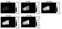
- FIG. 3 illustrates a state in which five heat generating units are connected in series according to another exemplary embodiment of the present invention.
- FIG. 4 is a photograph showing a heat generation state before voltage application and 20 minutes after voltage application to the heating element shown in FIG. 3.
- Figure 5 illustrates the configuration of a heating element according to another embodiment of the present invention.
- FIG. 6 shows an example in which the heat generating means is short-circuited in the heat generating unit of the heating element according to another exemplary embodiment of the present invention.
- FIG. 7 is a view showing a relationship between the length (W) of the bus bar and the elevated temperature according to the first embodiment of the present invention.
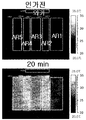
- FIG. 8 illustrates a state in which six heat generating units are connected in series according to another exemplary embodiment of the present invention.
- FIG. 9 is a photograph showing a heat generation state before voltage application and 20 minutes after voltage application to the heating element illustrated in FIG. 8.
- FIG. 10 is a diagram showing a relationship between an interval L between bus bars and a temperature increase temperature according to Embodiment 1 of the present invention.
- FIG. 10 is a diagram showing a relationship between an interval L between bus bars and a temperature increase temperature according to Embodiment 1 of the present invention.
- the heating element according to the present invention includes two or more heat generating units including two bus bars and conductive heating means electrically connected to the two bus bars, and the heat generating elements are connected to the bus bars of the heat generating units in series.
- the power per unit area of each of the heat generating units within is characterized in that the relationship decreases as the length of the bus bar increases.
- the power per unit area of each heat generating unit in the heating element satisfies the relationship that decreases as the length of the bus bar increases, but the power per unit area of each heat generating unit is equal to two powers in each heat generating unit. There may be no specific correlation with the spacing between bus bars.
- the power per unit area of each of the heat generating units decreases as the length of the bus bars increases. Can satisfy the relationship.
- the power per unit area of each heat generating unit may not have a specific correlation with the distance between two bus bars in each heat generating unit.
- the conductive heating means is electrically connected to the bus bar, when the voltage is applied to the bus bar means a means that can generate heat by its own resistance and thermal conductivity.
- a conductive material made of a plane or a line may be used.
- the heat generating means may be made of a transparent conductive material such as ITO, ZnO, or a thin film of an opaque conductive material.
- the heat generating means is linear, it may be made of a transparent or opaque conductive material. In the present invention, when the heat generating means is linear, even when the material is an opaque material such as metal, it is possible to configure the line width and the uniformity of the pattern as described below so as not to obstruct the visual field.
- the heat generating means is referred to as a conductive heat generating surface, and in the case of a linear shape, as a conductive heating wire.
- the extent of temperature rise is determined by power per unit area.
- the power per unit area of region A and region B of FIG. 1 may be calculated as follows.
- V 2 / (Rs ⁇ La / Wa) / (La ⁇ Wa) V 2 / (Rs ⁇ La 2 )
- V 2 / (Rs ⁇ Lb / Wb) / (Lb ⁇ Wb) V 2 / (Rs ⁇ Lb 2 )
- V is the voltage applied by the power supply unit
- Rs is the sheet resistance (Ohm / square) of the heating element.
- the power per unit area of region A and region B of FIG. 2 may be calculated as follows.
- V is the voltage applied by the power supply unit
- Rs is the sheet resistance (Ohm / square) of the heating element
- i is a constant calculated as follows.
- the parallel connection method should control the distance between the bus bars (La, Lb).
- the parallel connection method By using the parallel connection method, there is an advantage in that heat can be generated simultaneously by connecting a plurality of heat generating units.
- the present invention by connecting two or more heat generating units in series, it is possible to easily adjust the amount of heat generated for each part by adjusting the lengths Wa and Wb of the bus bars.
- the spacing between each heat generating unit may be 2 cm or less, preferably 0.5 cm or less. When the distance between the heat generating units exceeds 2cm, a problem may occur in which heat generation of the space between the heat generating units is lowered.
- the heat generation amount of the heat generating unit may be 700W or less per m 2 , may be 300W or less, may be 100W or more.
- the heating element according to the present invention has excellent heat generating performance even at low voltage, for example, 30V or less or 20V or less, and thus may be usefully used in automobiles and the like.
- the lengths of the bus bars of at least two heat generating units of the heat generating units may be different from each other.
- the calorific values of at least two heat generating units of the heat generating units may be different from each other.
- the amount of heat generated in each of the heat generating units may be adjusted by adjusting the length of the bus bar of each of the heat generating units.
- the amount of heat generated between the heat generating units may be adjusted differently, or all of them may be adjusted within the same range.
- the sheet resistance or transmittance deviation between the heat generating units may be adjusted to be within 20%, 10%, or 5%.
- the heat generation amount in each of the heat generating units can be made the same by making the lengths of the bus bars the same. Therefore, even when the object to which the heating element according to the present invention is applied must be configured in a specific shape such as a side glass of a car, the length of the bus bar is the same, so that the heat resistance of each part is uniform, and the sheet resistance of the conductive heating surface is uniform.
- the pattern density of the conductive heating line may be uniform. When the pattern density of the conductive heating line is made uniform, the conductive heating line pattern may be prevented from covering the field of view.
- the temperature deviation in the heat generating unit is within 20%, or within 10%
- the sheet resistance or transmittance deviation between the heat generating units can be adjusted to be within 20%, within 10%, or within 5%.
- the conductive heating line is configured by making the difference in the pattern density between the heating units smaller. You can make the pattern inconspicuous.
- the conductive heating line may be a straight line, but various modifications such as curved lines, wavy lines, and zigzag lines are possible.
- the entire pattern of the conductive heating wires included in each of the two or more heating units may be determined at once in the form of a pattern to be described later.
- the conductive heating line may be provided as a stripe, a rhombus, a square grid, a circle, a wave pattern, a grid, a two-dimensional grid, or the like, and the light emitted from a certain light source is not limited thereto. It is desirable to be designed so that the optical properties are not impaired by diffraction and interference. That is, in order to minimize the regularity of the pattern, a pattern consisting of spacing and sine wave and lattice structure spacing and line thickness irregularly may be used. If necessary, the shape of the conductive heating line pattern may be a combination of two or more patterns.
- the pattern of the conductive heating line may include an irregular pattern.
- the irregular pattern may include a pattern having a standard deviation ratio (distance distribution ratio) of 2% or more with respect to an average value of distances between adjacent straight points of the conductive heating line when a straight line intersecting the conductive heating line is drawn. have.
- a standard deviation ratio distance distribution ratio
- the straight line crossing the conductive heating line may be a line having the smallest standard deviation of the distance between the straight line and the adjacent intersection points of the conductive heating line.
- the straight line intersecting the conductive heating line may be a straight line extending in a direction perpendicular to the tangent of the conductive heating line.
- a straight line crossing the conductive heating line may have 80 or more intersection points with the conductive heating line.
- the ratio of the standard deviation (distance distribution ratio) to the average value of the distance between the straight line crossing the conductive heating line and the adjacent intersection points of the conductive heating line may be 2% or more, 10% or more, and 20% or more.
- At least a part of the surface of the transparent substrate provided with the heating line pattern may be provided in the conductive heating line pattern of another form.
- the irregular pattern includes a pattern in which distributions are continuously closed figures, and a ratio of the standard deviation (area distribution ratio) to the average value of the areas of the closed figures is 2% or more. It may include.
- the ratio of the standard deviation (area distribution ratio) to the average value of the areas of the closed figures may be 2% or more, 10% or more, and 20% or more.
- At least a part of the surface of the transparent substrate provided with the heating line pattern having a ratio of the standard deviation (area distribution ratio) to the average value of the area of the closed figures is 2% or more may be provided in the conductive heating line pattern of another form.
- the patterns are completely irregular, there may be a difference between small and dense lines in the distribution of the lines. Such a distribution of lines may cause a noticeable problem no matter how thin the line width is.
- regularity and irregularity can be appropriately balanced when forming a heating line.
- the base unit may be determined so that the heating line does not stand out or the local heating occurs, and the heating line may be formed in an irregular pattern within the base unit.
- the visual distribution can be compensated by preventing the distribution of lines from being concentrated at any one point.
- the irregular pattern may include a conductive heating line pattern having a boundary form of figures constituting the Voronoi diagram.
- the conductive heating line pattern in the form of a boundary line of figures constituting the Voronoi diagram, it is possible to prevent moiré and minimize side effects caused by diffraction and interference of light.
- the Voronoi diagram if you place the points of the Voronoi diagram generator in the area you want to fill, each point fills the area closest to the point compared to the other points. Pattern in a way. For example, suppose that a large discount store in the country is displayed as a dot and consumers go to the nearest large discount store. That is, when the space is filled with a regular hexagon and each point of the regular hexagon is selected as a Voronoi generator, the honeycomb structure may be the conductive heating line pattern.
- the conductive heating line pattern is formed using the Voronoi diagram generator, a complex pattern shape that can minimize side effects due to diffraction and interference of light can be easily determined.
- a pattern derived from the generator can be used by regularly or irregularly positioning the Voronoi diagram generator.
- the conductive heating line pattern is formed in the shape of the boundary line of the figures constituting the Voronoi diagram, in order to solve the problem of visual perception as described above, regularity and irregularity can be appropriately balanced when generating the Voronoi diagram generator. . For example, after designating an area of a certain size as a basic unit for the area to be patterned, a point is generated so that the distribution of points in the basic unit is irregular, and then a Voronoi pattern may be manufactured. Using this method, the visual distribution can be compensated by preventing the distribution of lines from being concentrated at any one point.
- the number per unit area of the Voronoi diagram generator may be adjusted to consider the visibility of the heating line or to match the heating density required by the display device.
- the unit area may be 5 cm 2 or less, and 1 cm 2 or less.
- the number per unit area of the Voronoi diagram generator may be selected from 25 to 2,500 pieces / cm 2 , and may be selected from 100 to 2,000 pieces / cm 2 .
- At least one of the figures constituting the pattern within the unit area may have a shape different from the remaining figures.
- the irregular pattern may include a conductive heating line pattern in the form of a boundary line of figures consisting of at least one triangle constituting the Delaunay pattern.
- the conductive heating line pattern has a boundary line shape of triangles constituting the Delaunay pattern, or a boundary line shape of figures consisting of at least two triangles constituting the Delaunay pattern, or a combination thereof.
- Delaunay pattern is a pattern that is called the Delaunay pattern generator in the area to fill the pattern and connects three surrounding points to form a triangle, but includes all the vertices of the triangle.
- a pattern is formed by drawing a triangle so that no other point exists in the circle.
- Delaunay triangulation and circulation may be repeated based on the Delaunay pattern generator.
- the Delaunay triangulation can be performed in such a way as to avoid the skinny triangle by maximizing the minimum angle of all angles of the triangle.
- the concept of the Delaunay pattern was proposed in 1934 by Boris Delaunay.
- the pattern in the form of a boundary line of figures consisting of at least one triangle constituting the Delaunay pattern may use a pattern derived from the generator by regularly or irregularly positioning the location of the Delaunay pattern generator.
- the conductive heating line pattern is formed using the Delaunay pattern generator, there is an advantage that the complex pattern shape can be easily determined.
- the conductive heating line pattern is formed in the form of a boundary line of figures consisting of at least one triangle constituting the Delaunay pattern, in order to solve the problem of visual perception as described above, regularity and irregularity when generating the Delaunay pattern generator Can be appropriately harmonized.
- the number per unit area of the Delaunay pattern generator may be adjusted. At this time, when adjusting the number per unit area of the Delaunay pattern generator, the unit area may be 5 cm 2 or less, and may be 1 cm 2 or less. The number per unit area of the Delaunay pattern generator may be selected from 25 to 2,500 pieces / cm 2 , and may be selected from 100 to 2,000 pieces / cm 2 .
- At least one of the figures constituting the pattern within the unit area may have a shape different from the remaining figures.
- the opening ratio of the conductive heating line pattern may be constant in the unit area.
- the heating element may have a transmittance deviation of 5% or less for any circle having a diameter of 20 cm. In this case, the heating element can prevent local heating. In addition, the heating element may be within 20% of the standard deviation of the surface temperature of the transparent substrate after the heating.
- the conductive heating line may be disposed so that a temperature deviation occurs in the heating element.
- the conductive heating line pattern may be formed such that a pattern area made of asymmetrical figures is 10% or more with respect to the entire pattern area.
- at least one of the lines connecting the center point of one figure constituting the Voronoi diagram with the center point of the adjacent figure forming the boundary with the figure is 10% of the total conductive heating line pattern area. It can be formed so that it may become abnormal.
- at least one side of the figure consisting of at least one triangle constituting the Delaunay pattern is formed so that the pattern area consisting of figures different in length from the other side is 10% or more with respect to the area where the pattern of the entire conductive heating line is formed. Can be.
- a large area pattern may be manufactured by using a method of designing a pattern in a limited area and then repeatedly connecting the limited area.
- the repetitive patterns may be connected to each other by fixing the positions of the points of each quadrangle.
- the limited area may have an area of 1 cm 2 or more, and an area of 10 cm 2 or more in order to minimize the moiré phenomenon and the diffraction and interference of light by repetition.
- the line width is thin on a transparent substrate and precise conductive heating line pattern Can be formed.
- a Voronoi diagram generator or a Delaunay pattern generator can be used, thereby making it possible to easily determine a complex pattern shape.
- the Voronoi diagram generator and the Delaunay pattern generator mean points arranged to form the Voronoi diagram and the Delaunay pattern as described above.
- the scope of the present invention is not limited thereto, and other methods may be used when determining the desired pattern form.
- the printing method may be performed by transferring a paste containing a conductive heating wire material onto a transparent substrate in the form of a desired pattern and then baking the paste.
- the transfer method is not particularly limited, and the pattern may be formed on a pattern transfer medium such as an intaglio or a screen, and a desired pattern may be transferred onto the transparent substrate using the pattern.
- the method of forming a pattern shape on the pattern transfer medium may use a method known in the art.
- the printing method is not particularly limited, and printing methods such as offset printing, screen printing, and gravure printing may be used.
- Offset printing may be performed by filling a paste on a patterned intaglio and then performing a primary transfer with a silicone rubber called a blanket, and then performing a secondary transfer by bringing the blanket and the transparent substrate into close contact with each other.
- Screen printing may be performed by placing the paste on a patterned screen and then placing the paste on the substrate directly through the screen where the space is empty while pushing the squeegee.
- Gravure printing may be performed by winding a blanket engraved with a pattern on a roll, filling a paste into a pattern, and then transferring the transparent substrate.
- the above schemes as well as the schemes may be used in combination. It is also possible to use a printing method known to those skilled in the art.
- the intaglio may be manufactured by precisely etching a glass having a desired conductive heating line pattern engraved thereon, or may be metal or DLC (Diamond-like Carbon) coating on the glass surface for durability.
- the intaglio may be produced by etching a metal plate.
- an offset printing method may be used to implement a more precise conductive heating line pattern.
- a doctor blade is used as a first step to fill a pattern of intaglio, and then the blanket is rotated to first transfer, and as a second step, the blanket is rotated to make a surface of the transparent substrate.
- the photolithography step is not limited to the printing method described above.
- a conductive heating line pattern material layer is formed on the entire surface of the transparent substrate, a photoresist layer is formed thereon, the photoresist layer is patterned by a selective exposure and development process, and then the patterned photoresist is formed.
- the layer may be used as a mask to etch the conductive heating pattern material layer to pattern the conductive heating line and to remove the photoresist layer.
- the conductive heating line pattern material layer may be formed by laminating a metal thin film such as copper, aluminum, or silver using an adhesive layer on a transparent substrate.
- the conductive heating line pattern material layer may be a metal layer formed on a transparent substrate by sputtering or physical vapor deposition.
- the conductive heating wire pattern material layer may be formed of a multi-layered structure of a metal such as Mo, Ni, Cr, Ti, which has good electrical conductivity, such as copper, aluminum, and silver, and is well adhered to the substrate. .
- the thickness of the metal thin film may be 20 micrometers or less, and may be 10 micrometers or less.
- the photoresist layer may be formed using a printing process instead of the photolithography process in the photolithography process.
- the present invention may also utilize a photography method.
- the photosensitive material may be patterned by selective exposure and development processes. More detailed examples are as follows.
- a negative photosensitive material is apply
- a polymer film such as PET or acetyl celluloid may be used as the substrate.
- the polymer film material coated with the photosensitive material will be referred to herein as a film.
- the negative photosensitive material may be generally composed of silver halide mixed with some AgI in AgBr which is very sensitive to light and regularly reacts with light. Since the image processed by photographing a general negative photosensitive material is negative in contrast with a subject, contrast, photographing may be performed using a mask having a pattern shape to be formed, preferably an irregular pattern shape.
- Plating may be further performed to increase the conductivity of the heating line pattern formed by using photolithography and a photolithography process.
- the plating may use an electroless plating method, and copper or nickel may be used as the plating material, and nickel plating may be performed thereon after copper plating, but the scope of the present invention is limited only to these examples. It is not.
- the present invention may also use a method using a mask.
- a mask having a heating line pattern shape may be positioned near the substrate, and then patterned using a method of depositing the heating line pattern material on the substrate.
- the deposition method may be a thermal vapor deposition method by heat or electron beam and a physical vapor deposition (PVD) method such as sputter, or a chemical vapor deposition (CVD) method using an organometallic material. It can also be used.
- PVD physical vapor deposition
- CVD chemical vapor deposition
- the heating element may be provided on a transparent substrate.
- the transparent substrate is not particularly limited, but light transmittance may be 50% or more, and 75% or more.
- glass may be used as the transparent substrate, or a plastic substrate or a plastic film may be used.
- the glass may be bonded to at least one surface of the substrate.
- the glass or plastic substrate may be bonded to the surface on which the conductive heating line pattern of the transparent substrate is formed.
- the plastic substrate or film may be a material known in the art, for example, polyethylene terephthalate (PET), polyvinylbutyral (PVB), polyethylene naphthalate (PEN), polyethersulfon (PES), polycarbonate (PC), acetyl celluloid and
- PET polyethylene terephthalate
- PVB polyvinylbutyral
- PEN polyethylene naphthalate
- PS polyethersulfon
- PC polycarbonate
- acetyl celluloid acetyl celluloid
- the film may have the same visible light transmittance of 80% or more.
- the plastic film may have a thickness of 12.5 to 500 micrometers and 50 to 250 micrometers.
- a metal having excellent thermal conductivity may be used as a material of the conductive heating wire.
- the specific resistance value of the conductive heating wire material may have a value of 1 microOhm cm or more and 200 microOhm cm or less.
- the conductive heating wire material copper, silver, carbon nanotubes (CNT), or the like may be used, and silver is most preferred.
- the conductive heating wire material may be used in the form of particles. In the present invention, copper particles coated with silver may also be used as the conductive heating wire material.
- the paste when the conductive heating wire is manufactured using a printing process using a paste, the paste may further include an organic binder in addition to the conductive heating wire material described above to facilitate the printing process.
- the organic binder may have a volatilization property in a sintering process.
- the organic binder may be a polyacrylic resin, a polyurethane resin, a polyester resin, a polyolefin resin, a polycarbonate resin, a cellulose resin, a polyimide resin, a polyethylene naphthalate resin, a modified epoxy, and the like. It is not limited only to.
- the paste may further include glass frit.
- the glass frit may be selected from commercially available products, but it is preferable to use an environmentally friendly glass frit free of lead.
- the glass frit used should have an average aperture of 2 micrometers or less and a maximum aperture of 50 micrometers or less.
- a solvent may be further added to the paste.
- the solvent may include butyl carbitol acetate, carbitol acetate, cyclohexanon, cellosolve acetate, terpineol, and the like. The scope of the present invention is not limited.
- the weight ratio of each component is 50 to 90% by weight of the conductive heating wire material, 1 to 20% by weight of the organic binder, glass frit 0.1 ⁇ 10% by weight and the solvent 1 to 20% by weight is preferable.
- a heating line having conductivity is formed when the paste is printed and then fired.
- the firing temperature is not particularly limited, but may be 500 to 800 ° C, and may be 600 to 700 ° C.
- the transparent substrate forming the heating wire pattern is glass
- the glass may be molded to suit the intended use, such as for building or automobile, in the firing step if necessary.
- the paste may be calcined in the step of forming an automotive glass into a curved surface.
- the baking may be performed at a relatively low temperature. For example, it can be carried out at 50 to 350 °C.
- the line width of the conductive heating wire may be 100 micrometers or less, 30 micrometers or less, 25 micrometers or less, 10 micrometers or less, even more preferably 7 micrometers or less, and 5 micrometers or less. have.
- the line width of the conductive heating wire may be 0.1 micrometer or more and 0.2 micrometer or more.
- the line spacing of the conductive heating wire may be 30 mm or less, 0.1 micrometers to 1 mm, 0.2 micrometers to 600 micrometers, or less, and 250 micrometers or less.
- the height of the heating wire may be 100 micrometers or less, 10 micrometers or less, or 2 micrometers or less.
- the line width and line height of the heating wire can be made uniform by the aforementioned methods.
- the uniformity of the heating line may be within the range of ⁇ 3 micrometers in the case of the line width, and may be within the range of ⁇ 1 micrometer in the case of the line height.
- the conductive heating surface may be formed of a transparent conductive material.
- the transparent conductive material include ITO and ZnO-based transparent conductive oxides.
- the transparent conductive oxide may be formed by sputtering, a sol-gel method, or a vapor deposition method, and has a thickness of 10 to 1,000 nm.
- the opaque conductive material may be formed by coating a thickness of 1 ⁇ 100nm.
- the opaque conductive material may be Ag, Au, Cu, Al, carbon nanotubes (carbon nanotube).
- the heating element according to the present invention may further include a power supply unit connected to the bus bar.
- the bus bar and the power supply unit may be formed using a method known in the art.
- the bus bar may be formed simultaneously with the formation of the conductive heating means or may be formed using the same or different printing method after the conductive heating means is formed.
- a bus bar may be formed through screen printing. In this case, the thickness of the bus bar may be 1 to 100 micrometers, and may be 10 to 50 micrometers.
- connection between the bus bar and the power supply unit can be made through physical contact with a structure having good soldering and conductive heat generation.
- a black pattern may be formed.
- the black pattern may be printed using a paste containing cobalt oxide.
- the printing method is suitable for screen printing, the thickness is 10 ⁇ 100 micrometers is appropriate.
- the conductive heating means and the bus bar may be formed before or after the black pattern is formed, respectively.
- the heating element according to the present invention may include an additional transparent substrate provided on the side provided with the conductive heating means of the transparent substrate.
- an additional transparent substrate provided on the side provided with the conductive heating means of the transparent substrate.
- glass, a plastic substrate or a film may be used as described above.
- the bonding film may be sandwiched between the conductive heating means and the additional transparent substrate when the additional transparent substrate is bonded. Temperature and pressure can be controlled during the bonding process.
- any material having adhesion and becoming transparent after bonding can be used.
- PVB film, EVA film, PU film and the like can be used, but is not limited to these examples.
- the bonding film is not particularly limited, but may have a thickness of 100 to 800 micrometers.
- the adhesive film is inserted between the transparent substrate on which the conductive heating means is formed and the additional transparent substrate, and put it in a vacuum bag to increase the temperature under reduced pressure, or raise the temperature using a hot roll,
- the primary junction is achieved by removing the air.
- the pressure, temperature and time is different depending on the type of adhesive film, but the pressure is usually 300 ⁇ 700 torr, it can gradually raise the temperature from room temperature to 100 °C. At this time, the time may be usually within 1 hour.
- the pre-bonded laminate is subjected to the secondary bonding process by the autoclaving process of applying pressure in the autoclave and raising the temperature. Secondary bonding may vary depending on the type of adhesive film, but may be slowly cooled after 1 hour to 3 hours, or about 2 hours at a pressure of 140 bar or more and a temperature of about 130 to 150 ° C.
- a method of bonding in one step using a vacuum laminator device may be used.
- the temperature can be gradually reduced to 80 to 150 ° C. while being cooled slowly, to 100 ° C. under reduced pressure ( ⁇ 5 mbar), and then pressurized ( ⁇ 1,000 mbar) to join.
- the heating element according to the present invention may have a shape forming a curved surface.
- the opening ratio of the conductive heating line pattern when the heating means is linear, the opening ratio of the conductive heating line pattern, that is, the ratio of the region not covered by the pattern may be 70% or more.
- the heating element according to the present invention has an excellent heat generation property that can increase the temperature while maintaining an opening ratio of 70% or more while maintaining a temperature deviation of 10% or less within 5 minutes after the heating operation.
- the heating element according to the present invention may be connected to a power source for heat generation, in which the calorific value may be 700 W or less per m 2 , 300 W or less, and 100 W or more.
- the heating element according to the present invention has excellent heat generating performance even at low voltage, for example, 30V or less, or 20V or less, and thus may be usefully used in automobiles and the like.
- the resistance in the heating element may be 5 ohms / square or less, 1 ohms / square or less, or 0.5 ohms / square or less.
- the heating element according to the present invention can be applied to glass or display devices used in various transportation means such as automobiles, ships, railways, high speed trains, airplanes, or houses or other buildings.
- the heating element according to the present invention not only has excellent heat generating characteristics even at low voltage, but also minimizes side effects due to diffraction and interference of the light source after sunset, and can be formed inconspicuously with the line width as described above. Unlike technology, it can also be applied to the windshield of vehicles such as automobiles.
- heating element according to the present invention may be applied to a display device.
- 3D TVs based on liquid crystal have been implemented to realize 3D images by binocular disparity.
- the most common way to generate binocular parallax is to use glasses with shutters synchronized with the playback frequency of the liquid crystal display.
- the left and right eye images should be alternately displayed on the liquid crystal display.
- the left and right eye images may overlap. Due to the overlapping phenomenon, the viewer may feel an unnatural 3D effect, and thus dizziness may occur.
- the movement of the liquid crystal used in the liquid crystal display may change in speed depending on the ambient temperature. That is, when driving a liquid crystal display at a low temperature, the liquid crystal change rate becomes slow, and when driving a liquid crystal display at a high temperature, the liquid crystal change rate becomes faster.
- heat generated in the backlight unit may affect the liquid crystal speed.
- the heat generated from the backlight unit may increase the temperature around the backlight unit, resulting in a deviation of the liquid crystal driving speed, thereby resulting in a 3D image.
- the non-ideal implementation of can be deepened.
- the present invention by applying the above-described heating element to a display device, especially a liquid crystal display, not only can excellent display characteristics be achieved during initial driving at low temperature, but also when the light source such as an edge type light source is located on the side surface of the light source. Even when a temperature deviation occurs in the entire display screen depending on the position, it is possible to provide uniform display characteristics throughout the display screen. In particular, it is possible to minimize the 3D image distortion generated in the 3D display device by increasing the ambient temperature of the liquid crystal by providing a heat generating function to the liquid crystal display, thereby realizing a high liquid crystal change rate.
- the display device may include a display panel and a heating element provided on at least one side of the display panel.
- the display device includes an edge type light source
- the heat generating unit disposed close to the light source among the heat generating elements relatively lengthens the bus bar
- the heat generating unit disposed far from the light source decreases the length of the bus bar relatively short.
- the temperature deviation according to the light source can be compensated for. As described above, while the local heating is performed to compensate for the temperature deviation, the visibility of the surface of the conductive heating surface or the pattern density of the conductive heating line is uniform in the entire display screen of the display device, thereby ensuring visibility.
- the display panel may be provided on the separate transparent substrate, or may be provided on one component of the display panel or other components of the display device.
- the display panel may include two substrates and a liquid crystal cell including a liquid crystal material encapsulated between the substrates, and the heating element may be provided inside or outside at least one of the substrates.
- the display panel may include polarizing plates provided on both sides of the liquid crystal cell, and the heating element may be provided on a phase difference compensation film provided between at least one of the liquid crystal cell and the polarizing plate.
- the polarizing plate includes a polarizing film and at least one protective film
- the heating element may be provided on at least one side of the protective film.
- the display device may include a backlight unit.
- the backlight unit may include a direct type light source or an edge type light source.
- the backlight unit may further include a light guide plate.
- the light source may be disposed at one or more edge portions of the light guide plate.
- the light source may be disposed only on one side of the light guide plate, and may be disposed at two to four edge portions.
- the heating element may be provided on the front side or the rear side of the backlight unit. In addition, the heating element may be provided directly on the front or rear of the light guide plate.
- the heating element When the heating element is provided on a separate transparent substrate, the heating element may be provided on the front or rear of the display panel, may be provided between the liquid crystal cell and at least one polarizing plate, between the display panel and the light source, the light guide plate It may be provided in the front or rear of the.
- the pattern of the conductive heating line may include an irregular pattern.
- the moire phenomenon of the display device can be prevented by an irregular pattern.
- the display device may include the heating element, and adjust the configuration of the heating element to prevent excessive heat generation and power consumption in the electronic product.
- the configuration of the heat generating film included in the display device according to the present invention may be adjusted such that power consumption, voltage, and heat generation amount are within a range as described below.
- the heating element included in the display device according to the present invention may use power consumption of 100 W or less when connected to a power source. If the power consumption exceeds 100W, 3D image distortion due to temperature rise is improved, but it may affect the power saving performance of the product due to the increased power consumption.
- the heating element of the display device according to the present invention may use a voltage of 20V or less, and a voltage of 12V or less. When the voltage exceeds 20 V, it is preferable to use a voltage as low as possible because there is a risk of electric shock due to a short circuit.
- Surface temperature of the display device using the heating element according to the invention is characterized in that it is controlled at 40 °C or less. Increasing the temperature to more than 40 °C can minimize the 3D image distortion, there is a problem that the power consumption may exceed 100W.
- the heating value may be 400 W or less per m 2 , or 200 W or less.
- the display device using the heating element according to the present invention may include the heating element described above, and may be provided with a control device for controlling the surface temperature in order to implement power saving products currently pursued by electronic products.
- the control device may control the surface temperature of the display device to 40 ° C. or less.
- the control device may have a function of generating heat only for a predetermined time by using a timer, and may have a function of attaching a temperature sensor to a surface of the display device to increase the temperature to a proper temperature and cut off power.
- the control device may perform a function for minimizing power consumption of the display device.
- the conductive heat generating means of the heat generating unit when at least one bus bar of at least one of the heat generating units is disposed diagonally, the conductive heat generating means of the heat generating unit includes a portion in which the current is shorted, whereby the current is shortest between the bus bars. It is concentrated in the diagonal direction which is a distance, and can prevent local heat generation.
- the current in order to equally adjust the bus bar length between the heat generating units, for example, when the bus bars are arranged diagonally as shown in FIG. 5, the current is a diagonal line in which the current is the shortest distance between the bus bars. Direction, so that local heating may occur around the diagonal of the shortest distance.
- the conductive heating means may be short-circuited at intervals of 0.1 to 20 mm along the bus bar in the area where the bus bar is diagonally disposed.
- An example of shorting the conductive heating means is illustrated in FIG. 6.
- the heat generating unit was disposed on the transparent substrate in the structure as shown in FIG. 3. At this time, the interval between each heat generating unit is 1mm and the length (W) of the bus bar was configured as shown in Table 1 below.
- the sheet resistance of the conductive heating wire provided between the bus bars of each heating unit was 0.33 ohm / square, the voltage / current was 21.6V and 3.8A, the power was 82.1W, and the length L between the bus bars was 70cm.
- Table 1 show average temperatures measured before and after voltage application of the heating element manufactured in Example 1, 20 minutes after voltage application.
- the relationship between the length (W) of the bus bar and the elevated temperature is shown in FIG. 7.
- the heat generating unit was disposed only on the rectangle indicated by the dotted line in the structure as shown in FIG. At this time, the interval between each heat generating unit was 1mm and the length (W) of the bus bar and the distance (L) between the bus bar was configured as shown in Table 2.
- the sheet resistance of the conductive heating wire provided between the bus bars of each heating unit was 0.33 ohm / square, the voltage / current was 14V and 2.4A, respectively, and the power was 33.6W.
- Table 2 show the average temperatures measured before the voltage application and 20 minutes after the voltage application of the heating element manufactured in Example 2.
- FIG. 10 the relationship between the bus bar interval L and the elevated temperature is shown in FIG. 10.
- the power per unit area in one heat generating unit can be fixed by the length of the bus bar, thereby adjusting the length of the bus bar for each heat generating unit.
- the calorific value of each part can be easily adjusted, thereby providing a heating element having no difference in permeability or sheet resistance between the heating units.
Landscapes
- Engineering & Computer Science (AREA)
- Manufacturing & Machinery (AREA)
- Chemical & Material Sciences (AREA)
- Ceramic Engineering (AREA)
- Surface Heating Bodies (AREA)
- Resistance Heating (AREA)
Abstract
The present invention relates to a heating element which comprises at least two heating units comprising two bus bars and an electrically-conductive heating means electrically connected to the two bus bars, and in which the bus bars of the heating units are connected to each other in series; wherein there is a relationship whereby the power per unit surface area of each of the heating units in the heating element decreases as the length of the bus bars increases. The present invention also relates to a production method for the heating element.
Description
본 출원은 2011년 1월 13일에 한국특허청에 제출된 한국 특허 출원 제10-2011-0003475호의 출원일의 이익을 주장하며, 그 내용 전부는 본 명세서에 포함된다.This application claims the benefit of the filing date of Korean Patent Application No. 10-2011-0003475 filed with the Korea Intellectual Property Office on January 13, 2011, the entire contents of which are incorporated herein.
본 발명은 발열체 및 이의 제조방법에 관한 것이다. 더욱 구체적으로, 부위별 발열량의 조절이 용이한 발열체 및 이의 제조방법에 관한 것이다.The present invention relates to a heating element and a method of manufacturing the same. More specifically, the present invention relates to a heating element and a method for manufacturing the same, the amount of heat generated by each part is easy to control.
겨울철이나 비 오는 날에는 자동차 외부와 내부의 온도 차이에 의해 자동차 유리에 성에가 발생한다. 또한, 실내 스키장의 경우 슬로프가 있는 내부와 슬로프 외부의 온도 차이에 의해 결로 현상이 발생한다. 이를 해결하기 위하여 발열 유리가 개발되었다. 발열 유리는 유리 표면에 열선 시트를 부착하거나 유리 표면에 직접 열선을 형성한 후 열선의 양 단자에 전기를 인가하여 열선으로부터 열을 발생시키고 이에 의하여 유리 표면의 온도를 올리는 개념을 이용한다.In winter or on rainy days, frost occurs on the glass of the car due to temperature differences between the outside and inside of the car. In addition, in the case of indoor ski resorts, dew condensation occurs due to the temperature difference between the slope inside and the slope outside. In order to solve this problem, a heating glass has been developed. The heating glass utilizes the concept of attaching a hot wire sheet to the glass surface or forming a hot wire directly on the glass surface and applying heat to both terminals of the hot wire to generate heat from the hot wire, thereby raising the temperature of the glass surface.
자동차용 또는 건축용 발열 유리는 열을 원활히 발생시키기 위하여 낮은 저항을 갖는 것도 중요하지만, 사람 눈에 거슬리지 않아야 한다. 이 때문에 기존의 투명 발열 유리는 ITO(Indium Tin Oxide)나 Ag 박막과 같은 투명 도전 재료를 스퍼터링(Sputtering) 공정을 통해 발열층을 형성한 후에 전극을 앞 끝단에 연결하여 제조하는 방법들이 제안이 되었다. 그러나, 이와 같은 방법에 의하여 제조된 발열유리는 높은 면저항으로 인하여 40V 이하의 저전압에서 구동되기 힘든 문제가 있었다. 따라서, 40V 이하의 전압에서 발열을 하고자 할 때에는 금속선을 이용하고자 하는 시도가 이루어지고 있다.It is also important that automotive or architectural pyrogenic glass has a low resistance in order to generate heat well, but it should not be distracting to human eyes. For this reason, the conventional transparent heating glass has been proposed to manufacture a transparent conductive material such as ITO (Indium Tin Oxide) or Ag thin film by sputtering process to form an exothermic layer and then connect the electrode to the front end. . However, the heating glass manufactured by this method has a problem that it is difficult to drive at a low voltage of 40V or less due to the high sheet resistance. Therefore, when attempting to generate heat at a voltage of 40V or less has been attempted to use a metal wire.
한편, 기존 발열체에서는 전원과 연결되는 1쌍의 버스 바를 사용하거나, 병렬 연결된 2쌍 이상의 버스 바를 사용하여, 버스 바 사이의 간격에 의하여 발열량을 조절하는 방법이 시도된 바 있다. 이 경우 버스 바 사이의 간격이 고정된 경우 부위별로 발열량을 조절하기 위해서는 버스 바 사이의 발열체의 면저항을 조절하여야 한다. 발열체의 면저항을 조절하기 위해서는 발열층을 이루는 전도성 물질의 두께를 조절하거나 발열 패턴으로서 금속 패턴을 이용하는 경우 금속 패턴의 밀도를 조절한다. 그런데, 전도성 물질의 두께 또는 발열 패턴의 밀도가 상이한 경우, 부위별 투과도 차이에 의하여 눈에 잘 띄는 문제가 있다.On the other hand, the conventional heating element has been attempted to adjust the amount of heat generated by the distance between the bus bars using a pair of bus bars connected to the power source, or using two or more pairs of bus bars connected in parallel. In this case, in order to control the amount of heat generated for each part when the space between the bus bars is fixed, the sheet resistance of the heating elements between the bus bars should be adjusted. In order to control the sheet resistance of the heating element, the thickness of the conductive material constituting the heating layer is adjusted or when the metal pattern is used as the heating pattern, the density of the metal pattern is adjusted. By the way, when the thickness of the conductive material or the density of the heating pattern is different, there is a problem that is noticeable by the difference in permeability.
본 발명은 전술한 종래기술의 문제를 해결하기 위하여 부위별 발열량의 조절이 용이하고 시야를 방해하지 않는 발열체 및 이의 제조방법을 제공하는 것을 목적으로 한다.An object of the present invention is to provide a heating element and a method of manufacturing the same, which is easy to control the amount of heat generated by each part and does not obstruct the field of view in order to solve the above problems of the prior art.
본 발명은 2개의 버스 바 및 상기 2개의 버스 바에 전기적으로 연결된 전도성 발열 수단을 포함하는 발열 유닛을 2개 이상 포함하고, 상기 발열 유닛들의 버스 바가 서로 직렬로 연결되는 발열체이며, 상기 발열체 내에서 상기 각각의 발열 유닛의 단위면적당 파워는 버스 바의 길이가 증가할수록 감소하는 관계를 가지는 것을 특징으로 하는 발열체를 제공한다.The present invention includes two or more heat generating units including two bus bars and conductive heat generating means electrically connected to the two bus bars, wherein the bus bars of the heat generating units are connected to each other in series. The power per unit area of each heat generating unit is provided with a heating element characterized in that the relationship is reduced as the length of the bus bar increases.
본 발명은 투명 기재 상에 2개의 버스 바 및 상기 2개의 버스 바에 전기적으로 연결된 전도성 발열 수단을 포함하는 발열 유닛을 2개 이상 형성하는 단계; 및 상기 발열 유닛들의 버스 바를 서로 직렬로 연결하는 단계를 포함하는 발열체의 제조방법이고, 상기 발열체 내에서 상기 각각의 발열 유닛의 단위면적당 파워는 버스 바의 길이가 증가할수록 감소하는 관계를 가지는 것을 특징으로 하는 발열체의 제조방법을 제공한다.The present invention comprises the steps of forming at least two heat generating units comprising two bus bars and conductive heating means electrically connected to the two bus bars on a transparent substrate; And connecting bus bars of the heat generating units in series with each other, wherein power per unit area of each of the heat generating units in the heat generating body decreases as the length of the bus bar increases. It provides a method for producing a heating element.
본 발명에서는 2개 이상의 발열 유닛들의 버스 바를 직렬로 연결함으로써, 하나의 발열 유닛 내의 단위면적당 파워는 버스 바의 길이에 의하여 고정될 수 있으므로, 발열 유닛별로 버스 바의 길이를 조절함으로써 부위별 발열량을 용이하게 조절할 수 있으며, 이에 의하여 발열 유닛간 투과도 또는 면저항의 차이가 없는 발열체를 제공할 수 있다.In the present invention, by connecting the bus bars of two or more heat generating units in series, the power per unit area in one heat generating unit can be fixed by the length of the bus bar, thereby adjusting the length of the bus bar for each heat generating unit to control the amount of heat generated for each part. It can be easily adjusted, whereby it is possible to provide a heating element with no difference in permeability or sheet resistance between the heating unit.
도 1은 종래 기술에 따라 2개의 발열 유닛이 병렬로 연결되어 있는 상태를 예시한 것이다.1 illustrates a state in which two heat generating units are connected in parallel according to the related art.
도 2는 본 발명의 일 실시상태에 따라 2개의 발열 유닛이 직렬로 연결되어 있는 상태를 예시한 것이다.2 illustrates a state in which two heat generating units are connected in series according to an exemplary embodiment of the present invention.
도 3은 본 발명의 또 하나의 실시상태에 따라 5개의 발열 유닛을 직렬로 연결한 상태를 예시한 것이다.3 illustrates a state in which five heat generating units are connected in series according to another exemplary embodiment of the present invention.
도 4는 도 3에 도시한 발열체에 전압 인가 전과 전압 인가 후 20분 후의 발열 상태를 나타내는 사진이다.4 is a photograph showing a heat generation state before voltage application and 20 minutes after voltage application to the heating element shown in FIG. 3.
도 5는 본 발명의 또 하나의 실시상태에 따른 발열체의 구성을 예시한 것이다.Figure 5 illustrates the configuration of a heating element according to another embodiment of the present invention.
도 6은 본 발명의 또 하나의 실시상태에 따른 발열체의 발열 유닛 내에서 발열 수단을 단락시킨 예를 도시한 것이다.6 shows an example in which the heat generating means is short-circuited in the heat generating unit of the heating element according to another exemplary embodiment of the present invention.
도 7은 본 발명의 실시예 1에 따른 버스 바의 길이(W)와 승온온도 사이의 관계를 나타낸 도이다.7 is a view showing a relationship between the length (W) of the bus bar and the elevated temperature according to the first embodiment of the present invention.
도 8은 본 발명의 또 하나의 실시상태에 따라 6개의 발열 유닛을 직렬로 연결한 상태를 예시한 것이다.8 illustrates a state in which six heat generating units are connected in series according to another exemplary embodiment of the present invention.
도 9는 도 8에 도시한 발열체에 전압 인가 전과 전압 인가 후 20분 후의 발열 상태를 나타내는 사진이다.FIG. 9 is a photograph showing a heat generation state before voltage application and 20 minutes after voltage application to the heating element illustrated in FIG. 8.
도 10은 본 발명의 실시예 1에 따른 버스 바간 간격(L)과 승온온도 사이의 관계를 나타낸 도이다.FIG. 10 is a diagram showing a relationship between an interval L between bus bars and a temperature increase temperature according to Embodiment 1 of the present invention. FIG.
이하에서 본 발명에 대하여 상세히 설명한다.Hereinafter, the present invention will be described in detail.
본 발명에 따른 발열체는 2개의 버스 바 및 상기 2개의 버스 바에 전기적으로 연결된 전도성 발열 수단을 포함하는 발열 유닛을 2개 이상 포함하고, 상기 발열 유닛들의 버스 바가 서로 직렬로 연결되는 발열체이며, 상기 발열체 내에서 상기 각각의 발열 유닛의 단위면적당 파워는 버스 바의 길이가 증가할수록 감소하는 관계를 가지는 것을 특징으로 한다.The heating element according to the present invention includes two or more heat generating units including two bus bars and conductive heating means electrically connected to the two bus bars, and the heat generating elements are connected to the bus bars of the heat generating units in series. The power per unit area of each of the heat generating units within is characterized in that the relationship decreases as the length of the bus bar increases.
본 발명에 있어서, 상기 발열체 내에서 상기 각각의 발열 유닛의 단위면적당 파워는 버스 바의 길이가 증가할수록 감소하는 관계를 만족시키나, 상기 각각의 발열 유닛의 단위면적당 파워는 각각의 발열 유닛 내 2개의 버스 바간의 간격과는 특정한 상관관계가 없을 수 있다.In the present invention, the power per unit area of each heat generating unit in the heating element satisfies the relationship that decreases as the length of the bus bar increases, but the power per unit area of each heat generating unit is equal to two powers in each heat generating unit. There may be no specific correlation with the spacing between bus bars.
특히, 상기 발열체 내에서 상기 각각의 발열 유닛 내 2개의 버스 바간의 간격이 고정되는 경우에는 버스 바의 길이를 조절함으로써, 상기 각각의 발열 유닛의 단위면적당 파워는 버스 바의 길이가 증가할수록 감소하는 관계를 만족할 수 있다. 또한, 상기 발열체 내에서 상기 발열 유닛의 버스 바의 길이가 고정되는 경우에도 상기 각각의 발열 유닛의 단위면적당 파워는 각각의 발열 유닛 내 2개의 버스 바간의 간격과는 특정한 상관관계가 없을 수 있다.In particular, when the distance between two bus bars in each of the heat generating units is fixed in the heating element, by adjusting the length of the bus bars, the power per unit area of each of the heat generating units decreases as the length of the bus bars increases. Can satisfy the relationship. In addition, even when the length of the bus bar of the heat generating unit is fixed in the heat generating element, the power per unit area of each heat generating unit may not have a specific correlation with the distance between two bus bars in each heat generating unit.
본 발명에 있어서, 상기 전도성 발열 수단은 상기 버스 바에 전기적으로 연결되어, 상기 버스 바에 전압이 인가되는 경우, 그 자체가 갖는 저항 및 열전도성에 의하여 발열을 할 수 있는 수단을 의미한다. 상기 발열 수단으로는 면상 또는 선상으로 이루어진 전도성 재료가 사용될 수 있다. 상기 발열 수단이 면상인 경우 투명 전도성 재료, 예컨대 ITO, ZnO 등으로 이루어지거나, 불투명 전도성 재료의 박막으로 이루어질 수 있다. 상기 발열 수단이 선상인 경우 투명 또는 불투명한 전도성 재료로 이루어질 수 있다. 본 발명에서는, 상기 발열 수단이 선상인 경우, 그 재료가 금속과 같이 불투명한 재료인 경우에도 후술하는 바와 같이 선폭 및 패턴의 균일도를 조절함으로써, 시야를 방해하지 않도록 구성할 수 있다.In the present invention, the conductive heating means is electrically connected to the bus bar, when the voltage is applied to the bus bar means a means that can generate heat by its own resistance and thermal conductivity. As the heat generating means, a conductive material made of a plane or a line may be used. When the heat generating means is planar, it may be made of a transparent conductive material such as ITO, ZnO, or a thin film of an opaque conductive material. When the heat generating means is linear, it may be made of a transparent or opaque conductive material. In the present invention, when the heat generating means is linear, even when the material is an opaque material such as metal, it is possible to configure the line width and the uniformity of the pattern as described below so as not to obstruct the visual field.
본 명세서에서는 편의상 상기 발열 수단이 면상인 경우 전도성 발열면, 선상인 경우 전도성 발열선이라고 언급한다.In the present specification, for the sake of convenience, the heat generating means is referred to as a conductive heat generating surface, and in the case of a linear shape, as a conductive heating wire.
발열체를 이용한 발열의 경우, 온도의 상승 폭은 단위면적당 파워(power)에 의하여 결정된다.In the case of heat generation using a heating element, the extent of temperature rise is determined by power per unit area.
도 1에 도시한 바와 같이, 1쌍의 버스 바 및 그 사이에 구비된 전도성 발열 수단을 포함하는 2 이상의 발열 유닛이 병렬로 연결되는 경우, 단위면적당 파워는 버스 바 사이의 거리(La, Lb)에 의하여 결정된다. 도 1에 있어서, 녹색으로 표시된 양측 단부가 버스 바를 나타내고, 그 사이의 영역이 전도성 발열 수단이 구비된 영역을 나타낸다. 구체적으로, 도 1의 A 영역과 B 영역의 단위면적당 파워는 하기와 같이 계산될 수 있다.As shown in FIG. 1, when two or more heat generating units including a pair of bus bars and conductive heat generating means provided therebetween are connected in parallel, the power per unit area is the distance between the bus bars La and Lb. Is determined by. In Fig. 1, both ends indicated in green represent bus bars, and regions therebetween represent regions provided with conductive heating means. Specifically, the power per unit area of region A and region B of FIG. 1 may be calculated as follows.
A 영역: V2 / (Rs × La/Wa) / (La × Wa) = V2 / (Rs × La2)A area: V 2 / (Rs × La / Wa) / (La × Wa) = V 2 / (Rs × La 2 )
B 영역: V2 / (Rs × Lb/Wb) / (Lb × Wb) = V2 / (Rs × Lb2)B area: V 2 / (Rs × Lb / Wb) / (Lb × Wb) = V 2 / (Rs × Lb 2 )
상기 식에서, V는 전원부에 의하여 인가된 전압이고, Rs는 발열체의 면저항(Ohm/square)이다.In the above formula, V is the voltage applied by the power supply unit, and Rs is the sheet resistance (Ohm / square) of the heating element.
그러나, 도 2에 도시한 바와 같이 2 이상의 발열 유닛이 직렬로 연결되는 경우 단위면적당 파워는 버스 바의 길이(Wa, Wb)에 의하여 결정된다. 도 2에서도 마찬가지로, 녹색으로 표시된 양측 단부가 버스 바를 나타내고, 그 사이의 영역이 전도성 발열 수단이 구비된 영역을 나타낸다. 구체적으로, 도 2의 A 영역과 B 영역의 단위면적당 파워는 하기와 같이 계산될 수 있다.However, as shown in FIG. 2, when two or more heat generating units are connected in series, the power per unit area is determined by the lengths of the bus bars Wa and Wb. Similarly in Fig. 2, both ends shown in green represent bus bars, and regions therebetween represent regions provided with conductive heating means. Specifically, the power per unit area of region A and region B of FIG. 2 may be calculated as follows.
A 영역: i2 × Rs (La/Wa) / (La × Wa) = i2 × Rs / Wa2
A area: i 2 × Rs (La / Wa) / (La × Wa) = i 2 × Rs / Wa 2
B 영역: i2 × Rs (Lb/Wb) / (Lb × Wb) = i2 × Rs / Wb2
B area: i 2 × Rs (Lb / Wb) / (Lb × Wb) = i 2 × Rs / Wb 2
상기 식에서 V는 전원부에 의하여 인가된 전압이고, Rs는 발열체의 면저항(Ohm/square)이며, i는 하기와 같이 계산되는 상수이다.In the above formula, V is the voltage applied by the power supply unit, Rs is the sheet resistance (Ohm / square) of the heating element, i is a constant calculated as follows.
i = V / Rs (La / Wa + Lb / Wb)i = V / Rs (La / Wa + Lb / Wb)
부위별로 발열량을 조절하여야 하는 경우, 병렬 연결 방식은 버스 바 사이의 거리(La, Lb)를 조절하여야 한다.In the case where the heating value is to be adjusted for each part, the parallel connection method should control the distance between the bus bars (La, Lb).
상기의 병렬 연결 방식을 이용하면 다수의 발열 유닛을 연결하여 동시에 발열을 시킬 수 있는 장점이 있다. 또한, 한 가지 제품 내에서 발열 유닛을 나누어서 부위별 발열량을 조절할 수도 있다. 예를 들어, 자동차 유리 또는 디스플레이 장치에서는 버스 바 사이의 거리(La, Lb)를 조절하는 것 보다는 버스 바의 길이(Wa, Wb)를 조절하는 것이 용이하다. 따라서, 본 발명에서는 2 이상의 발열 유닛을 직렬로 연결함으로써, 버스 바의 길이(Wa, Wb)의 조절을 통하여 부위별로 발열량을 용이하게 조절할 수 있다. 한 가지 제품 내에 다수의 발열 유닛을 배치하는 경우, 각 발열 유닛 사이의 간격은 2cm 이하일 수 있고, 바람직하게는 0.5cm 이하일 수 있다. 상기 발열 유닛 간의 간격이 2cm를 초과하는 경우에는 발열 유닛 사이 공간의 발열이 저하되는 문제가 발생할 수 있다.By using the parallel connection method, there is an advantage in that heat can be generated simultaneously by connecting a plurality of heat generating units. In addition, it is also possible to control the amount of heat generated for each part by dividing the heat generating unit in one product. For example, in automobile glass or display devices, it is easier to adjust the lengths of the bus bars Wa and Wb than to adjust the distances La and Lb between the bus bars. Therefore, in the present invention, by connecting two or more heat generating units in series, it is possible to easily adjust the amount of heat generated for each part by adjusting the lengths Wa and Wb of the bus bars. When arranging a plurality of heat generating units in one product, the spacing between each heat generating unit may be 2 cm or less, preferably 0.5 cm or less. When the distance between the heat generating units exceeds 2cm, a problem may occur in which heat generation of the space between the heat generating units is lowered.
본 발명에 있어서, 상기 발열 유닛의 발열량은 m2 당 700W 이하일 수 있고, 300W 이하일 수 있으며, 100W 이상일 수 있다. 본 발명에 따른 발열체는 저전압, 예컨대 30V 이하 또는 20V 이하에서도 발열성능이 우수하므로, 자동차 등에서도 유용하게 사용될 수 있다.In the present invention, the heat generation amount of the heat generating unit may be 700W or less per m 2 , may be 300W or less, may be 100W or more. The heating element according to the present invention has excellent heat generating performance even at low voltage, for example, 30V or less or 20V or less, and thus may be usefully used in automobiles and the like.
본 발명에 있어서, 상기 발열 유닛들 중 적어도 2개의 발열 유닛의 버스 바의 길이는 서로 상이할 수 있다. 또한, 상기 발열 유닛들 중 적어도 2개의 발열 유닛의 발열량은 서로 상이할 수 있다.In the present invention, the lengths of the bus bars of at least two heat generating units of the heat generating units may be different from each other. In addition, the calorific values of at least two heat generating units of the heat generating units may be different from each other.
본 발명에서는 각 발열 유닛의 버스 바의 길이를 조절함으로써 각 발열 유닛에서의 발열량을 조절할 수 있으므로, 발열 유닛들간의 발열량을 서로 다르게 조절할 수도 있고, 모두 동등한 범위 내로 조절할 수도 있다. 다만, 발열량을 상기와 같이 조절하면서도 발열 유닛들 간의 면저항 또는 투과율 편차가 20% 이내, 10% 이내, 또는 5% 이내가 되도록 조절할 수 있다.In the present invention, the amount of heat generated in each of the heat generating units may be adjusted by adjusting the length of the bus bar of each of the heat generating units. Thus, the amount of heat generated between the heat generating units may be adjusted differently, or all of them may be adjusted within the same range. However, while adjusting the amount of heat generated as described above, the sheet resistance or transmittance deviation between the heat generating units may be adjusted to be within 20%, 10%, or 5%.
본 발명의 일 실시상태에 따른 발열체에서 발열 유닛들이 직렬로 연결된 예를 도 5에 도시하였다. 도 5에서는 버스 바들의 길이를 동일하게 함으로써 각 발열 유닛들에서의 발열량을 동일하게 할 수 있다. 따라서, 본 발명에 따른 발열체가 적용되는 대상이 자동차의 옆유리와 같이 특정 형태로 구성되어야 하는 경우에도, 버스 바의 길이를 동일하게 구성함으로써, 부위별 발열량을 균일하게 하면서도, 전도성 발열면의 면저항 또는 전도성 발열선의 패턴 밀도를 균일할 수 있다. 전도성 발열선의 패턴 밀도를 균일하게 하는 경우 전도성 발열선 패턴이 시야를 가리지 않도록 할 수 있다. 예컨대, 본 발명에 따르면 발열 유닛 내의 온도 편차가 20% 이내, 또는 10% 이내이면서, 발열 유닛들 간의 면저항 또는 투과율 편차가 20% 이내, 10% 이내, 또는 5% 이내가 되도록 조절할 수 있다. 전도성 발열선의 패턴 밀도가 발열 유닛간에 상이한 경우에는 부위별 투과율 차이에 의하여 상기 전도성 발열선 패턴이 시야에 잘 띄는 문제가 있으나, 본 발명에서는 상기와 같이 발열 유닛간 패턴 밀도의 차이가 적게 구성함으로써 전도성 발열선 패턴이 눈에 띄지 않도록 할 수 있다.5 illustrates an example in which the heating units are connected in series in the heating element according to the exemplary embodiment of the present invention. In FIG. 5, the heat generation amount in each of the heat generating units can be made the same by making the lengths of the bus bars the same. Therefore, even when the object to which the heating element according to the present invention is applied must be configured in a specific shape such as a side glass of a car, the length of the bus bar is the same, so that the heat resistance of each part is uniform, and the sheet resistance of the conductive heating surface is uniform. Alternatively, the pattern density of the conductive heating line may be uniform. When the pattern density of the conductive heating line is made uniform, the conductive heating line pattern may be prevented from covering the field of view. For example, according to the present invention, the temperature deviation in the heat generating unit is within 20%, or within 10%, and the sheet resistance or transmittance deviation between the heat generating units can be adjusted to be within 20%, within 10%, or within 5%. When the pattern density of the conductive heating wire is different between the heating units, there is a problem that the conductive heating wire pattern is visible in the field of view due to the difference in transmittance for each region, but in the present invention, the conductive heating line is configured by making the difference in the pattern density between the heating units smaller. You can make the pattern inconspicuous.
상기에서는 발열 유닛간의 발열량의 차이가 없도록 구성한 예를 설명하였지만, 같은 작용원리를 이용하여 발열 유닛간의 발열량이 다르면서도 발열 유닛들 간의 면저항 또는 투과율 편차가 20% 이내, 10% 이내, 또는 5% 이내가 되도록 조절할 수 있다.In the above, an example is described in which there is no difference in the amount of heat generated between the heat generating units. However, using the same principle, the heat resistance between the heat generating units is different, and the sheet resistance or transmittance deviation between the heat generating units is within 20%, 10%, or 5%. Can be adjusted to
본 발명에 있어서, 상기 전도성 발열선은 직선일 수도 있으나, 곡선, 물결선, 지그재그선 등 다양한 변형이 가능하다.In the present invention, the conductive heating line may be a straight line, but various modifications such as curved lines, wavy lines, and zigzag lines are possible.
본 발명에 있어서, 상기 2 이상의 발열 유닛 내에 각각 포함되는 전도성 발열선의 전체의 패턴을 후술하는 패턴의 형태로 한꺼번에 결정할 수 있다.In the present invention, the entire pattern of the conductive heating wires included in each of the two or more heating units may be determined at once in the form of a pattern to be described later.
상기 전도성 발열선은 스트라이프(Stripe), 마름모, 정사각형 격자, 원형, 웨이브(wave) 패턴, 그리드, 2차원 그리드 등의 패턴으로 구비될 수 있으며, 특정 형태로 제한되는 것은 아니나, 일정 광원에서 나오는 빛이 회절과 간섭에 의해서 광학적 성질을 저해하지 않도록 설계되는 것이 바람직하다. 즉, 패턴의 규칙성을 최소화하기 위해 물결무늬, 사인 곡선(Sine wave) 및 격자 구조의 스페이싱과 선의 두께를 불규칙하게 구성한 패턴을 사용할 수도 있다. 필요한 경우, 전도성 발열선 패턴의 형태는 2 이상의 패턴의 조합일 수 있다.The conductive heating line may be provided as a stripe, a rhombus, a square grid, a circle, a wave pattern, a grid, a two-dimensional grid, or the like, and the light emitted from a certain light source is not limited thereto. It is desirable to be designed so that the optical properties are not impaired by diffraction and interference. That is, in order to minimize the regularity of the pattern, a pattern consisting of spacing and sine wave and lattice structure spacing and line thickness irregularly may be used. If necessary, the shape of the conductive heating line pattern may be a combination of two or more patterns.
상기 전도성 발열선의 패턴은 불규칙 패턴을 포함할 수 있다.The pattern of the conductive heating line may include an irregular pattern.
상기 불규칙 패턴은 상기 전도성 발열선과 교차하는 직선을 그렸을 때, 상기 직선과 상기 전도성 발열선의 인접하는 교점들간의 거리의 평균값에 대한 표준 편차의 비율(거리 분포 비율)이 2% 이상인 패턴을 포함할 수 있다.The irregular pattern may include a pattern having a standard deviation ratio (distance distribution ratio) of 2% or more with respect to an average value of distances between adjacent straight points of the conductive heating line when a straight line intersecting the conductive heating line is drawn. have.
상기 전도성 발열선과 교차하는 직선은 상기 직선과 전도성 발열선의 인접하는 교점들간의 거리의 표준 편차가 가장 작은 선일 수 있다. 또는, 상기 전도성 발열선과 교차하는 직선은 상기 전도성 발열선의 어느 한 점의 접선에 대하여 수직한 방향으로 연장된 직선일 수 있다. 이와 같은 전도성 발열선 패턴을 이용함으로써, 광원의 회절과 간섭에 의한 부작용 및 모아레를 방지할 수 있다.The straight line crossing the conductive heating line may be a line having the smallest standard deviation of the distance between the straight line and the adjacent intersection points of the conductive heating line. Alternatively, the straight line intersecting the conductive heating line may be a straight line extending in a direction perpendicular to the tangent of the conductive heating line. By using such a conductive heating line pattern, side effects and moiré caused by diffraction and interference of the light source can be prevented.
상기 전도성 발열선과 교차하는 직선은 상기 전도성 발열선과의 교점이 80개 이상일 수 있다.A straight line crossing the conductive heating line may have 80 or more intersection points with the conductive heating line.
상기 전도성 발열선과 교차하는 직선과 상기 전도성 발열선의 인접하는 교점들간의 거리의 평균값에 대한 표준 편차의 비율(거리 분포 비율)이 2% 이상일 수 있고, 10% 이상일 수 있으며, 20% 이상일 수 있다.The ratio of the standard deviation (distance distribution ratio) to the average value of the distance between the straight line crossing the conductive heating line and the adjacent intersection points of the conductive heating line may be 2% or more, 10% or more, and 20% or more.
상기와 같은 발열선 패턴이 구비된 투명기재의 표면의 적어도 일부에는 다른 형태의 전도성 발열선 패턴에 구비될 수도 있다.At least a part of the surface of the transparent substrate provided with the heating line pattern may be provided in the conductive heating line pattern of another form.
본 발명의 또 하나의 실시상태에 따르면, 상기 불규칙 패턴은 분포가 연속적인 폐쇄 도형들로 이루어지고, 상기 폐쇄 도형들의 면적의 평균값에 대한 표준 편차의 비율(면적 분포 비율)이 2% 이상인 패턴을 포함할 수 있다. 이와 같은 전도성 발열선 패턴을 이용함으로써, 광원의 회절과 간섭에 의한 부작용 및 모아레를 방지할 수 있다.According to another exemplary embodiment of the present invention, the irregular pattern includes a pattern in which distributions are continuously closed figures, and a ratio of the standard deviation (area distribution ratio) to the average value of the areas of the closed figures is 2% or more. It may include. By using such a conductive heating line pattern, side effects and moiré caused by diffraction and interference of the light source can be prevented.
상기 폐쇄도형은 적어도 100개 존재할 수 있다.There may be at least 100 closed figures.
상기 폐쇄 도형들의 면적의 평균값에 대한 표준 편차의 비율(면적 분포 비율)이 2% 이상일 수 있고, 10% 이상일 수 있으며, 20% 이상일 수 있다.The ratio of the standard deviation (area distribution ratio) to the average value of the areas of the closed figures may be 2% or more, 10% or more, and 20% or more.
상기 폐쇄 도형들의 면적의 평균값에 대한 표준 편차의 비율(면적 분포 비율)이 2% 이상인 상기와 같은 발열선 패턴이 구비된 투명기재의 표면의 적어도 일부에는 다른 형태의 전도성 발열선 패턴에 구비될 수도 있다.At least a part of the surface of the transparent substrate provided with the heating line pattern having a ratio of the standard deviation (area distribution ratio) to the average value of the area of the closed figures is 2% or more may be provided in the conductive heating line pattern of another form.
패턴들이 완전하게 불규칙한 경우 선의 분포에 있어서 소한 곳과 밀한 곳의 차이가 생길 수 있다. 이러한 선의 분포는 선폭이 아무리 얇더라도 눈에 띌 수 있는 문제가 생길 수 있다. 이와 같은 시각적인 인지성의 문제를 해결하기 위하여, 본 발명에서는 발열선을 형성할 때 규칙성과 불규칙성을 적절히 조화시킬 수 있다. 예컨대, 발열선이 눈에 띄거나 국부 발열이 발생하지 않도록 기본 단위를 정하고, 그 기본 단위 내에서 발열선을 불규칙적인 패턴으로 형성할 수 있다. 이와 같은 방법을 이용하면 선의 분포가 어느 한 지점에 몰리지 않게 함으로써 시각성을 보완할 수 있다.If the patterns are completely irregular, there may be a difference between small and dense lines in the distribution of the lines. Such a distribution of lines may cause a noticeable problem no matter how thin the line width is. In order to solve such a visual perception problem, in the present invention, regularity and irregularity can be appropriately balanced when forming a heating line. For example, the base unit may be determined so that the heating line does not stand out or the local heating occurs, and the heating line may be formed in an irregular pattern within the base unit. Using this method, the visual distribution can be compensated by preventing the distribution of lines from being concentrated at any one point.
본 발명의 또 하나의 실시상태에 따르면, 상기 불규칙 패턴은 보로노이 다이어그램을 이루는 도형들의 경계선 형태의 전도성 발열선 패턴을 포함할 수 있다.According to another exemplary embodiment of the present invention, the irregular pattern may include a conductive heating line pattern having a boundary form of figures constituting the Voronoi diagram.
상기 전도성 발열선 패턴을 보로노이 다이어그램을 이루는 도형들의 경계선 형태로 형성함으로써 모아레를 방지하고, 빛의 회절 및 간섭에 의한 부작용을 최소화할 수 있다. 보로노이 다이어그램(Voronoi diagram)이란, 채우고자 하는 영역에 보로노이 다이어그램 제너레이터(Voronoi diagram generator)라는 점들을 배치하면, 각 점들이 다른 점들로부터의 거리에 비하여 해당 점과의 거리가 가장 가까운 영역을 채우는 방식으로 이루어진 패턴이다. 예를 들어, 전국의 대형 할인점을 점으로 표시하고 소비자들은 가장 가까운 대형 할인점을 찾아간다고 할 때, 각 할인점의 상권을 표시하는 패턴을 예로 들 수 있다. 즉, 정육각형으로 공간을 채우고 정육각형들의 각점들을 보로노이 제너레이터로 선정하면 벌집(honeycomb) 구조가 상기 전도성 발열선 패턴이 될 수 있다. 본 발명에서 보로노이 다이어그램 제너레이터를 이용하여 전도성 발열선 패턴을 형성하는 경우, 빛의 회절 및 간섭에 의한 부작용을 최소화할 수 있는 복잡한 패턴 형태를 용이하게 결정할 수 있는 장점이 있다.By forming the conductive heating line pattern in the form of a boundary line of figures constituting the Voronoi diagram, it is possible to prevent moiré and minimize side effects caused by diffraction and interference of light. In the Voronoi diagram, if you place the points of the Voronoi diagram generator in the area you want to fill, each point fills the area closest to the point compared to the other points. Pattern in a way. For example, suppose that a large discount store in the country is displayed as a dot and consumers go to the nearest large discount store. That is, when the space is filled with a regular hexagon and each point of the regular hexagon is selected as a Voronoi generator, the honeycomb structure may be the conductive heating line pattern. In the present invention, when the conductive heating line pattern is formed using the Voronoi diagram generator, a complex pattern shape that can minimize side effects due to diffraction and interference of light can be easily determined.
본 발명에서는 보로노이 다이어그램 제너레이터의 위치를 규칙 또는 불규칙하게 위치시킴으로써 상기 제너레이터로부터 파생된 패턴을 이용할 수 있다.In the present invention, a pattern derived from the generator can be used by regularly or irregularly positioning the Voronoi diagram generator.
전도성 발열선 패턴을 보로노이 다이어그램을 이루는 도형들의 경계선 형태로 형성하는 경우에도, 전술한 바와 같은 시각적인 인지성의 문제를 해결하기 위하여, 보로노이 다이어그램 제너레이터를 생성할 때 규칙성과 불규칙성을 적절히 조화시킬 수 있다. 예를 들어, 패턴이 들어갈 면적에 일정크기의 면적을 기본 단위(unit)로 지정한 후, 기본 단위 안에서의 점의 분포가 불규칙성을 갖도록 점을 생성한 후 보로노이 패턴을 제작할 수도 있다. 이와 같은 방법을 이용하면 선의 분포가 어느 한 지점에 몰리지 않게 함으로써 시각성을 보완할 수 있다.Even when the conductive heating line pattern is formed in the shape of the boundary line of the figures constituting the Voronoi diagram, in order to solve the problem of visual perception as described above, regularity and irregularity can be appropriately balanced when generating the Voronoi diagram generator. . For example, after designating an area of a certain size as a basic unit for the area to be patterned, a point is generated so that the distribution of points in the basic unit is irregular, and then a Voronoi pattern may be manufactured. Using this method, the visual distribution can be compensated by preventing the distribution of lines from being concentrated at any one point.
전술한 바와 같이, 발열선의 시각성을 고려하거나, 표시장치에서 요구되는 발열 밀도를 맞추기 위하여 보로노이 다이어그램 제너레이터의 단위면적당 개수를 조절할 수 있다. 이 때, 보로노이 다이어그램 제너레이터의 단위면적당 개수를 조절시 상기 단위면적은 5 cm2 이하일 수 있고, 1 cm2 이하일 수 있다. 상기 보로노이 다이어그램 제너레이터의 단위면적당 개수는 25 ~ 2,500 개/cm2 내에서 선택할 수 있으며, 100 ~ 2,000 개/cm2 내에서 선택할 수 있다.As described above, the number per unit area of the Voronoi diagram generator may be adjusted to consider the visibility of the heating line or to match the heating density required by the display device. In this case, when adjusting the number per unit area of the Voronoi diagram generator, the unit area may be 5 cm 2 or less, and 1 cm 2 or less. The number per unit area of the Voronoi diagram generator may be selected from 25 to 2,500 pieces / cm 2 , and may be selected from 100 to 2,000 pieces / cm 2 .
상기 단위면적 내의 패턴을 구성하는 도형들 중 적어도 하나는 나머지 도형들과 상이한 형태를 가질 수 있다.At least one of the figures constituting the pattern within the unit area may have a shape different from the remaining figures.
본 발명의 또 하나의 실시상태에 따르면, 상기 불규칙 패턴은 델로니 패턴을 이루는 적어도 하나의 삼각형으로 이루어진 도형들의 경계선 형태의 전도성 발열선 패턴을 포함할 수 있다.According to another exemplary embodiment of the present invention, the irregular pattern may include a conductive heating line pattern in the form of a boundary line of figures consisting of at least one triangle constituting the Delaunay pattern.
구체적으로, 상기 전도성 발열선 패턴의 형태는 델로니 패턴을 구성하는 삼각형들의 경계선 형태이거나, 델로니 패턴을 구성하는 적어도 2개의 삼각형들로 이루어진 도형들의 경계선 형태이거나, 이들의 조합 형태이다.In detail, the conductive heating line pattern has a boundary line shape of triangles constituting the Delaunay pattern, or a boundary line shape of figures consisting of at least two triangles constituting the Delaunay pattern, or a combination thereof.
상기 전도성 발열선 패턴을 델로니 패턴을 이루는 적어도 하나의 삼각형으로 이루어진 도형들의 경계선 형태로 형성함으로써 모아레 현상 및 빛의 회절 및 간섭에 의한 부작용을 최소화할 수 있다. 델로니 패턴(Delaunay pattern)이란, 패턴을 채우고자 하는 영역에 델로니 패턴 제너레이터(generator)라는 점들을 배치하고, 주변에 위치한 3개의 점들을 서로 연결하여 삼각형을 그리되, 삼각형의 모든 꼭지점을 포함하는 원(circumcircle)을 그렸을 때, 상기 원 내에는 다른 점이 존재하지 않도록 삼각형을 그림으로써 형성된 패턴이다. 이와 같은 패턴을 형성하기 위하여, 델로니 페턴 제너레이터를 바탕으로 델로니 삼각형 분할(Delaunay triangulation)과 원그리기(circulation)를 반복할 수 있다. 상기 델로니 삼각형 분할은 삼각형의 모든 각의 최소 각도를 최대화하여 마른 체형의 삼각형을 피하는 방식으로 수행될 수 있다. 상기 델로니 패턴의 개념은 Boris Delaunay에 의하여 1934년에 제안되었다.By forming the conductive heating line pattern in the form of a boundary line of figures consisting of at least one triangle constituting the Delaunay pattern, it is possible to minimize side effects caused by moiré phenomenon and diffraction and interference of light. Delaunay pattern is a pattern that is called the Delaunay pattern generator in the area to fill the pattern and connects three surrounding points to form a triangle, but includes all the vertices of the triangle. When a circle is drawn, a pattern is formed by drawing a triangle so that no other point exists in the circle. In order to form such a pattern, Delaunay triangulation and circulation may be repeated based on the Delaunay pattern generator. The Delaunay triangulation can be performed in such a way as to avoid the skinny triangle by maximizing the minimum angle of all angles of the triangle. The concept of the Delaunay pattern was proposed in 1934 by Boris Delaunay.
상기 델로니 패턴을 이루는 적어도 하나의 삼각형으로 이루어진 도형들의 경계선 형태의 패턴은 델로니 패턴 제너레이터의 위치를 규칙 또는 불규칙하게 위치시킴으로써 상기 제너레이터로부터 파생된 패턴을 이용할 수 있다. 본 발명에서 델로니 패턴 제너레이터를 이용하여 전도성 발열선 패턴을 형성하는 경우, 복잡한 패턴 형태를 용이하게 결정할 수 있는 장점이 있다.The pattern in the form of a boundary line of figures consisting of at least one triangle constituting the Delaunay pattern may use a pattern derived from the generator by regularly or irregularly positioning the location of the Delaunay pattern generator. In the present invention, when the conductive heating line pattern is formed using the Delaunay pattern generator, there is an advantage that the complex pattern shape can be easily determined.
전도성 발열선 패턴을 델로니 패턴을 이루는 적어도 하나의 삼각형으로 이루어진 도형들의 경계선 형태로 형성하는 경우에도, 전술한 바와 같은 시각적인 인지성의 문제를 해결하기 위하여, 델로니 패턴 제너레이터를 생성할 때 규칙성과 불규칙성을 적절히 조화시킬 수 있다.Even when the conductive heating line pattern is formed in the form of a boundary line of figures consisting of at least one triangle constituting the Delaunay pattern, in order to solve the problem of visual perception as described above, regularity and irregularity when generating the Delaunay pattern generator Can be appropriately harmonized.
발열선의 시각성을 고려하거나, 표시장치에서 요구되는 발열 밀도를 맞추기 위하여, 델로니 패턴 제너레이터의 단위면적당 개수를 조절할 수 있다. 이 때, 델로니 패턴 제너레이터의 단위면적당 개수를 조절시 상기 단위면적은 5 cm2 이하일 수 있고, 1 cm2 이하일 수 있다. 상기 델로니 패턴 제너레이터의 단위면적당 개수는 25 ~ 2,500 개/cm2 내에서 선택할 수 있으며, 100 ~ 2,000 개/cm2 내에서 선택할 수 있다.In order to consider the visibility of the heating line or to match the heating density required by the display device, the number per unit area of the Delaunay pattern generator may be adjusted. At this time, when adjusting the number per unit area of the Delaunay pattern generator, the unit area may be 5 cm 2 or less, and may be 1 cm 2 or less. The number per unit area of the Delaunay pattern generator may be selected from 25 to 2,500 pieces / cm 2 , and may be selected from 100 to 2,000 pieces / cm 2 .
상기 단위면적 내의 패턴을 구성하는 도형들 중 적어도 하나는 나머지 도형들과 상이한 형태를 가질 수 있다.At least one of the figures constituting the pattern within the unit area may have a shape different from the remaining figures.
발열체의 균일한 발열 및 시각성을 위하여 전도성 발열선 패턴의 개구율이 단위면적에서 일정할 수 있다. 상기 발열체는 직경 20㎝의 임의의 원에 대한 투과율 편차가 5% 이하일 수 있다. 이 경우, 상기 발열체는 국부 발열을 방지할 수 있다. 또한, 상기 발열체는 발열 후 투명기재의 표면 온도의 표준 편차가 20% 이내일 수 있다. 다만, 특정 목적을 위하여, 발열체에서 온도편차가 발생하도록 전도성 발열선을 배치할 수도 있다.For uniform heating and visibility of the heating element, the opening ratio of the conductive heating line pattern may be constant in the unit area. The heating element may have a transmittance deviation of 5% or less for any circle having a diameter of 20 cm. In this case, the heating element can prevent local heating. In addition, the heating element may be within 20% of the standard deviation of the surface temperature of the transparent substrate after the heating. However, for a specific purpose, the conductive heating line may be disposed so that a temperature deviation occurs in the heating element.
모아레 방지 또는 빛의 회절과 간섭에 의한 부작용의 최소화 효과를 극대화하기 위하여, 상기 전도성 발열선 패턴을 비대칭 구조의 도형으로 이루어진 패턴 면적이 전체 패턴 면적에 대하여 10% 이상이 되도록 형성할 수 있다. 또한, 보로노이 다이어그램을 이루는 어느 한 도형의 중심점을 상기 도형과 경계를 이루는 인접 도형의 중심점과 연결한 선들 중 적어도 하나가 나머지 선들과 길이가 상이한 도형들의 면적이 전체 전도성 발열선 패턴 면적에 대하여 10% 이상이 되도록 형성할 수 있다. 또한, 상기 델로니 패턴을 이루는 적어도 하나의 삼각형으로 이루어진 도형을 이루는 적어도 한 변이 나머지 변과 길이가 상이한 도형들로 이루어진 패턴 면적이 전체 전도성 발열선의 패턴이 형성된 면적에 대하여 10% 이상이 되도록 형성할 수 있다.In order to maximize the effect of preventing moiré or minimizing side effects caused by diffraction and interference of light, the conductive heating line pattern may be formed such that a pattern area made of asymmetrical figures is 10% or more with respect to the entire pattern area. In addition, at least one of the lines connecting the center point of one figure constituting the Voronoi diagram with the center point of the adjacent figure forming the boundary with the figure is 10% of the total conductive heating line pattern area. It can be formed so that it may become abnormal. In addition, at least one side of the figure consisting of at least one triangle constituting the Delaunay pattern is formed so that the pattern area consisting of figures different in length from the other side is 10% or more with respect to the area where the pattern of the entire conductive heating line is formed. Can be.
상기 발열선 패턴의 제작시, 제한된 면적에 패턴을 디자인한 후 상기 제한된 면적을 반복적으로 연결하는 방식을 이용하는 방식을 이용함으로써 대면적 패턴을 제작할 수도 있다. 상기 패턴을 반복적으로 연결하기 위해서는 각 사변의 점들의 위치를 고정함으로써 반복적인 패턴이 서로 연결되게 만들 수 있다. 이 때 제한된 면적은 반복에 의한 모아레 현상 및 빛의 회절과 간섭을 최소화하기 위하여 1 cm2 이상의 면적을 가질 수 있고, 10 cm2 이상의 면적을 가질 수 있다.When the heating line pattern is manufactured, a large area pattern may be manufactured by using a method of designing a pattern in a limited area and then repeatedly connecting the limited area. In order to repeatedly connect the patterns, the repetitive patterns may be connected to each other by fixing the positions of the points of each quadrangle. In this case, the limited area may have an area of 1 cm 2 or more, and an area of 10 cm 2 or more in order to minimize the moiré phenomenon and the diffraction and interference of light by repetition.
본 발명에서는 우선 목적하는 패턴 형태를 결정한 후, 인쇄법, 포토리소그래피법, 포토그래피법, 마스크를 이용한 방법, 스퍼터링법, 또는 잉크젯 법 등을 이용함으로써 투명기재 상에 선폭이 얇으며 정밀한 전도성 발열선 패턴을 형성할 수 있다. 상기 패턴 형태의 결정시 보로노이 다이어그램 제너레이터 또는 델로니 패턴 제너레이트를 이용할 수 있으며, 이에 의하여 복잡한 패턴 형태를 용이하게 결정할 수 있다. 여기서, 상기 보로노이 다이어그램 제너레이터 및 델로니 패턴 제너레이터란 각각 전술한 바와 같이 보로노이 다이어그램 및 델로니 패턴을 형성할 수 있도록 배치된 점들을 의미한다. 그러나, 본 발명의 범위가 그것에 한정되는 것은 아니며, 목적하는 패턴 형태의 결정시 그 이외의 방법을 이용할 수도 있다.In the present invention, first, after determining the desired pattern shape, by using a printing method, a photolithography method, a photography method, a method using a mask, a sputtering method, or an inkjet method, the line width is thin on a transparent substrate and precise conductive heating line pattern Can be formed. When determining the pattern shape, a Voronoi diagram generator or a Delaunay pattern generator can be used, thereby making it possible to easily determine a complex pattern shape. Here, the Voronoi diagram generator and the Delaunay pattern generator mean points arranged to form the Voronoi diagram and the Delaunay pattern as described above. However, the scope of the present invention is not limited thereto, and other methods may be used when determining the desired pattern form.
상기 인쇄법은 전도성 발열선 재료를 포함하는 페이스트를 목적하는 패턴 형태로 투명기재 상에 전사한 후 소성하는 방식으로 수행될 수 있다. 상기 전사방법으로는 특별히 한정되지 않으나, 요판 또는 스크린 등 패턴 전사 매체에 상기 패턴 형태를 형성하고, 이를 이용하여 원하는 패턴을 투명기재에 전사할 수 있다. 상기 패턴 전사 매체에 패턴 형태를 형성하는 방법은 당 기술분야에 알려져 있는 방법을 이용할 수 있다.The printing method may be performed by transferring a paste containing a conductive heating wire material onto a transparent substrate in the form of a desired pattern and then baking the paste. The transfer method is not particularly limited, and the pattern may be formed on a pattern transfer medium such as an intaglio or a screen, and a desired pattern may be transferred onto the transparent substrate using the pattern. The method of forming a pattern shape on the pattern transfer medium may use a method known in the art.
상기 인쇄법으로는 특별히 한정되지 않으며, 오프셋 인쇄, 스크린 인쇄, 그라비아 인쇄 등의 인쇄법이 사용될 수 있다. 오프셋 인쇄는 패턴이 새겨진 요판에 페이스트를 채운 후 블랑킷(blanket)이라고 부르는 실리콘 고무로 1차 전사를 시킨 후, 블랑킷과 투명기재를 밀착시켜 2차 전사를 시키는 방식으로 수행될 수 있다. 스크린 인쇄는 패턴이 있는 스크린 위에 페이스트를 위치시킨 후, 스퀴지를 밀면서 공간이 비워져 있는 스크린을 통하여 직접적으로 기재에 페이스트를 위치시키는 방식으로 수행될 수 있다. 그라비아 인쇄는 롤 위에 패턴이 새겨진 블랑킷을 감고 페이스트를 패턴 안에 채운 후, 투명기재에 전사시키는 방식으로 수행될 수 있다. 본 발명에서는 상기 방식 뿐만 아니라 상기 방식들이 복합적으로 사용될 수도 있다. 또한 그외의 당업자들에게 알려진 인쇄 방식을 사용할 수도 있다.The printing method is not particularly limited, and printing methods such as offset printing, screen printing, and gravure printing may be used. Offset printing may be performed by filling a paste on a patterned intaglio and then performing a primary transfer with a silicone rubber called a blanket, and then performing a secondary transfer by bringing the blanket and the transparent substrate into close contact with each other. Screen printing may be performed by placing the paste on a patterned screen and then placing the paste on the substrate directly through the screen where the space is empty while pushing the squeegee. Gravure printing may be performed by winding a blanket engraved with a pattern on a roll, filling a paste into a pattern, and then transferring the transparent substrate. In the present invention, the above schemes as well as the schemes may be used in combination. It is also possible to use a printing method known to those skilled in the art.
오프셋 인쇄법의 경우, 블랑킷이 갖는 이형 특성으로 인하여 페이스트가 유리와 같은 투명기재에 거의 대부분 전사되기 때문에 별도의 블랑킷 세정공정이 필요하지 않다. 상기 요판은 목적하는 전도성 발열선 패턴이 새겨진 유리를 정밀 에칭하여 제조할 수 있으며, 내구성을 위하여 유리 표면에 금속 또는 DLC(Diamond-like Carbon) 코팅을 할 수도 있다. 상기 요판은 금속판을 에칭하여 제조할 수도 있다.In the case of the offset printing method, a blanket cleaning process is not necessary because the paste is almost transferred to a transparent substrate such as glass due to the release property of the blanket. The intaglio may be manufactured by precisely etching a glass having a desired conductive heating line pattern engraved thereon, or may be metal or DLC (Diamond-like Carbon) coating on the glass surface for durability. The intaglio may be produced by etching a metal plate.
본 발명에서는 보다 정밀한 전도성 발열선 패턴을 구현하기 위하여 오프셋 인쇄법을 이용할 수 있다. 오프셋 인쇄방법은, 제1 단계로서 닥터 블레이드(Doctor Blade)를 이용하여 요판의 패턴에 페이스트를 채운 후, 블랑킷을 회전시켜 1차 전사하고, 제2 단계로서 블랑킷을 회전시켜 투명기재의 표면에 2차 전사한다.In the present invention, an offset printing method may be used to implement a more precise conductive heating line pattern. In the offset printing method, a doctor blade is used as a first step to fill a pattern of intaglio, and then the blanket is rotated to first transfer, and as a second step, the blanket is rotated to make a surface of the transparent substrate. 2nd Warrior
본 발명에서는 전술한 인쇄법에 한정되지 않고, 포토리소그래피 공정을 사용할 수도 있다. 예컨대, 포토리소그래피 공정은 투명기재의 전면에 전도성 발열선 패턴 재료층을 형성하고, 그 위에 포토레지스트층을 형성하고, 선택적 노광 및 현상 공정에 의하여 포토레지스트층을 패턴화한 후, 패턴화된 포토레지스트층을 마스크로 이용하여 전도성 발열 패턴 재료층을 에칭함으로써 전도성 발열선을 패턴화하고, 포토레지스트층을 제거하는 방식으로 수행될 수 있다.In the present invention, the photolithography step is not limited to the printing method described above. For example, in the photolithography process, a conductive heating line pattern material layer is formed on the entire surface of the transparent substrate, a photoresist layer is formed thereon, the photoresist layer is patterned by a selective exposure and development process, and then the patterned photoresist is formed. The layer may be used as a mask to etch the conductive heating pattern material layer to pattern the conductive heating line and to remove the photoresist layer.
상기 전도성 발열선 패턴 재료층은 투명기재 위에 접착층을 이용하여 구리, 알루미늄, 은과 같은 금속 박막을 라미네이션함으로써 형성할 수도 있다. 또한, 상기 전도성 발열선 패턴 재료층은 투명기재 위에 스퍼터링 또는 물리적 증착방법(physical vapor deposition) 방식을 이용하여 형성한 금속층일 수도 있다. 이 때, 상기 전도성 발열선 패턴 재료층은 구리, 알루미늄, 은과 같은 전기전도도가 좋은 금속과 기재와의 부착이 좋고 색상이 어두운 Mo, Ni, Cr, Ti와 같은 금속의 다층 구조로 형성될 수도 있다. 이 때, 금속 박막의 두께는 20 마이크로미터 이하일 수 있고, 10 마이크로미터 이하일 수 있다.The conductive heating line pattern material layer may be formed by laminating a metal thin film such as copper, aluminum, or silver using an adhesive layer on a transparent substrate. In addition, the conductive heating line pattern material layer may be a metal layer formed on a transparent substrate by sputtering or physical vapor deposition. In this case, the conductive heating wire pattern material layer may be formed of a multi-layered structure of a metal such as Mo, Ni, Cr, Ti, which has good electrical conductivity, such as copper, aluminum, and silver, and is well adhered to the substrate. . In this case, the thickness of the metal thin film may be 20 micrometers or less, and may be 10 micrometers or less.
본 발명에서는 상기의 포토리소그래피 공정에서 포토리소그래피 공정 대신 인쇄 공정을 이용하여 포토레지스트층을 형성할 수도 있다.In the present invention, the photoresist layer may be formed using a printing process instead of the photolithography process in the photolithography process.
본 발명은 또한 포토그래피 방법을 이용할 수도 있다. 예를 들어 투명기재 상에 할로겐화은을 포함한 사진 감광재료를 도포한 후, 상기 감광재료를 선택적 노광 및 현상 공정에 의하여 패턴을 형성할 수도 있다. 좀 더 상세한 예를 들면 하기와 같다. 우선, 패턴을 형성하고자 하는 기재 위에 네거티브용 감광재료를 도포한다. 이 때, 기재로는 PET, 아세틸 셀룰로이드 등의 고분자 필름이 사용될 수 있다. 감광재료가 도포된 고분자 필름재를 여기서 필름이라 칭하기로 한다. 상기 네거티브용 감광재료는 일반적으로 빛에 대해 매우 민감하고 규칙적인 반응을 하는 AgBr에 약간의 AgI를 섞은 할로겐화은(Silver Halide)으로 구성할 수 있다. 일반적인 네거티브용 감광재료를 촬영하여 현상 처리된 화상은 피사체와 명암이 반대인 음화이므로, 형성하고자 하는 패턴 형상, 바람직하게는 불규칙한 패턴 형상을 갖는 마스크(mask)를 이용하여 촬영을 진행할 수 있다.The present invention may also utilize a photography method. For example, after applying a photosensitive material containing silver halide on a transparent substrate, the photosensitive material may be patterned by selective exposure and development processes. More detailed examples are as follows. First, a negative photosensitive material is apply | coated on the base material to form a pattern. In this case, a polymer film such as PET or acetyl celluloid may be used as the substrate. The polymer film material coated with the photosensitive material will be referred to herein as a film. The negative photosensitive material may be generally composed of silver halide mixed with some AgI in AgBr which is very sensitive to light and regularly reacts with light. Since the image processed by photographing a general negative photosensitive material is negative in contrast with a subject, contrast, photographing may be performed using a mask having a pattern shape to be formed, preferably an irregular pattern shape.
포토리소그래피와 포토그래피 공정을 이용하여 형성된 상기 발열선 패턴의 전도도를 높이기 위하여 도금처리를 추가로 수행할 수도 있다. 상기 도금은 무전해 도금 방법을 이용할 수 있으며, 도금 재료로는 구리 또는 니켈을 사용할 수 있으며, 구리도금을 수행한 후 그 위에 니켈 도금을 수행할 수 있으나, 본 발명의 범위가 이들 예로만 한정되는 것은 아니다.Plating may be further performed to increase the conductivity of the heating line pattern formed by using photolithography and a photolithography process. The plating may use an electroless plating method, and copper or nickel may be used as the plating material, and nickel plating may be performed thereon after copper plating, but the scope of the present invention is limited only to these examples. It is not.
본 발명은 또한 마스크를 이용한 방법을 이용할 수도 있다. 예를 들어 발열선 패턴 형상을 갖는 마스크를 기재 가까이에 위치한 후, 발열선 패턴 재료를 기재에 증착하는 방식을 사용하여 패턴화할 수도 있다. 이 때, 증착을 하는 방식은 열 또는 전자빔에 의한 열 증착법 및 스퍼터(sputter)와 같은 PVD(physical vapor deposition) 방식을 이용할 수도 있고, 유기금속(organometal) 재료를 이용한 CVD(chemical vapor deposition) 방식을 이용할 수도 있다.The present invention may also use a method using a mask. For example, a mask having a heating line pattern shape may be positioned near the substrate, and then patterned using a method of depositing the heating line pattern material on the substrate. At this time, the deposition method may be a thermal vapor deposition method by heat or electron beam and a physical vapor deposition (PVD) method such as sputter, or a chemical vapor deposition (CVD) method using an organometallic material. It can also be used.
본 발명에 있어서, 상기 발열체는 투명기재 상에 구비될 수 있다.In the present invention, the heating element may be provided on a transparent substrate.
상기 투명 기재는 특별히 한정되지 않으나, 빛투과율이 50% 이상일 수 있고, 75% 이상일 수 있다. 구체적으로, 상기 투명기재로는 유리를 사용할 수도 있고, 플라스틱 기판 또는 플라스틱 필름을 사용할 수 있다. 플라스틱 필름을 사용하는 경우에는 전도성 발열선 패턴을 형성한 후, 기재의 적어도 일면에 유리를 합착할 수 있다. 이 때, 투명기재의 전도성 발열선 패턴이 형성된 면에 유리 또는 플라스틱 기판을 합착할 수 있다. 상기 플라스틱 기판 또는 필름으로는 당 기술분야에 알려져 있는 재료를 사용할 수 있으며, 예컨대 PET(Polyethylene terephthalate), PVB(polyvinylbutyral), PEN(polyethylene naphthalate), PES(polyethersulfon), PC(polycarbonate), 아세틸 셀룰로이드와 같은 가시광 투과율 80% 이상의 필름일 수 있다. 상기 플라스틱 필름의 두께는 12.5 내지 500 마이크로미터일 수 있고, 50 내지 250 마이크로미터일 수 있다.The transparent substrate is not particularly limited, but light transmittance may be 50% or more, and 75% or more. Specifically, glass may be used as the transparent substrate, or a plastic substrate or a plastic film may be used. When using a plastic film, after forming a conductive heating line pattern, the glass may be bonded to at least one surface of the substrate. In this case, the glass or plastic substrate may be bonded to the surface on which the conductive heating line pattern of the transparent substrate is formed. The plastic substrate or film may be a material known in the art, for example, polyethylene terephthalate (PET), polyvinylbutyral (PVB), polyethylene naphthalate (PEN), polyethersulfon (PES), polycarbonate (PC), acetyl celluloid and The film may have the same visible light transmittance of 80% or more. The plastic film may have a thickness of 12.5 to 500 micrometers and 50 to 250 micrometers.
본 발명에 있어서, 상기 전도성 발열선의 재료로는 열전도도가 우수한 금속을 사용할 수 있다. 또한, 상기 전도성 발열선 재료의 비저항 값은 1 microOhm cm 이상 200 microOhm cm 이하의 값을 가질 수 있다. 전도성 발열선 재료의 구체적인 예로서, 구리, 은(silver), 탄소나노튜브(CNT) 등이 사용될 수 있고, 은이 가장 바람직하다. 상기 전도성 발열선 재료는 입자 형태로 사용할 수 있다. 본 발명에 있어서, 전도성 발열선 재료로서 은으로 코팅된 구리 입자도 사용될 수 있다.In the present invention, a metal having excellent thermal conductivity may be used as a material of the conductive heating wire. In addition, the specific resistance value of the conductive heating wire material may have a value of 1 microOhm cm or more and 200 microOhm cm or less. As a specific example of the conductive heating wire material, copper, silver, carbon nanotubes (CNT), or the like may be used, and silver is most preferred. The conductive heating wire material may be used in the form of particles. In the present invention, copper particles coated with silver may also be used as the conductive heating wire material.
본 발명에 있어서, 상기 전도성 발열선을 페이스트를 이용한 인쇄 공정을 이용하여 제조하는 경우, 상기 페이스트는 인쇄 공정이 용이하도록 전술한 전도성 발열선 재료 이외에 유기 바인더를 더 포함할 수도 있다. 상기 유기 바인더는 소성 공정에서 휘발되는 성질을 가질 수 있다. 상기 유기 바인더로는 폴리아크릴계 수지, 폴리우레탄계 수지, 폴리에스테르계 수지, 폴리올레핀계 수지, 폴리카보네이트계 수지, 셀룰로우즈 수지, 폴리이미드계 수지, 폴리에틸렌 나프탈레이트계 수지 및 변성 에폭시 등이 있으나, 이들에만 한정되는 것은 아니다.In the present invention, when the conductive heating wire is manufactured using a printing process using a paste, the paste may further include an organic binder in addition to the conductive heating wire material described above to facilitate the printing process. The organic binder may have a volatilization property in a sintering process. The organic binder may be a polyacrylic resin, a polyurethane resin, a polyester resin, a polyolefin resin, a polycarbonate resin, a cellulose resin, a polyimide resin, a polyethylene naphthalate resin, a modified epoxy, and the like. It is not limited only to.
유리와 같은 투명기재에 대한 페이스트의 부착력을 향상시키기 위하여, 상기 페이스트는 글래스 프릿(Glass Frit)을 더 포함할 수 있다. 상기 글래스 프릿은 시판품으로부터 선택할 수 있으나, 친환경적인 납성분이 없는 글래스 프릿을 사용하는 것이 좋다. 이때 사용하는 글래스 프릿의 크기는 평균 구경이 2 마이크로미터 이하이고 최대 구경이 50 마이크로미터 이하의 것이 좋다.In order to improve the adhesion of the paste to a transparent substrate such as glass, the paste may further include glass frit. The glass frit may be selected from commercially available products, but it is preferable to use an environmentally friendly glass frit free of lead. The glass frit used should have an average aperture of 2 micrometers or less and a maximum aperture of 50 micrometers or less.
필요에 따라, 상기 페이스트에는 용매가 더 추가될 수 있다. 상기 용매로는 부틸 카르비톨 아세테이트 (Butyl Carbitol Acetate), 카르비톨 아세테이트 (Carbitol acetate), 시클로 헥사논(Cyclohexanon), 셀로솔브 아세테이트 (Cellosolve Acetate) 및 테르피놀(Terpineol) 등이 있으나, 이들 예에 의하여 본 발명의 범위가 한정되는 것은 아니다.If necessary, a solvent may be further added to the paste. The solvent may include butyl carbitol acetate, carbitol acetate, cyclohexanon, cellosolve acetate, terpineol, and the like. The scope of the present invention is not limited.
본 발명에 있어서, 전도성 발열선 재료, 유기 바인더, 글래스 프릿 및 용매를 포함하는 페이스트를 사용하는 경우, 각 성분의 중량비는 전도성 발열선 재료 50 ~ 90 중량%, 유기 바인더 1 ~ 20 중량%, 글래스 프릿 0.1 ~ 10 중량% 및 용매 1 ~ 20 중량%로 하는 것이 좋다.In the present invention, when using a paste containing a conductive heating wire material, an organic binder, a glass frit and a solvent, the weight ratio of each component is 50 to 90% by weight of the conductive heating wire material, 1 to 20% by weight of the organic binder, glass frit 0.1 ~ 10% by weight and the solvent 1 to 20% by weight is preferable.
본 발명에 있어서, 전술한 페이스트를 이용하는 경우, 페이스트를 인쇄한 후 소성 과정을 거치면 전도성을 갖는 발열선이 형성된다. 이 때, 소성온도는 특별히 한정되지 않으나, 500 ~ 800℃일 수 있고, 600 ~ 700℃일 수 있다. 상기 발열선 패턴을 형성하는 투명기재가 유리인 경우, 필요한 경우 상기 소성 단계에서 상기 유리를 건축용 또는 자동차용 등의 목적 용도에 맞도록 성형을 할 수 있다. 예컨대 자동차용 유리를 곡면으로 성형하는 단계에서 상기 페이스트를 소성할 수도 있다. 또한, 상기 전도성 발열선 패턴을 형성하는 투명기재로서 플라스틱 기판 또는 필름을 사용하는 경우에는 비교적 저온에서 소성을 수행할 수 있다. 예컨대, 50 내지 350?에서 수행할 수 있다.In the present invention, in the case of using the above-described paste, a heating line having conductivity is formed when the paste is printed and then fired. At this time, the firing temperature is not particularly limited, but may be 500 to 800 ° C, and may be 600 to 700 ° C. When the transparent substrate forming the heating wire pattern is glass, the glass may be molded to suit the intended use, such as for building or automobile, in the firing step if necessary. For example, the paste may be calcined in the step of forming an automotive glass into a curved surface. In addition, when the plastic substrate or the film is used as the transparent substrate forming the conductive heating line pattern, the baking may be performed at a relatively low temperature. For example, it can be carried out at 50 to 350 ℃.
상기 전도성 발열선의 선폭은 100 마이크로미터 이하일 수 있고, 30 마이크로미터 이하일 수 있으며, 25 마이크로미터 이하일 수 있고, 10 마이크로미터 이하일 수 있으며, 더더욱 바람직하게는 7 마이크로미터 이하일 수 있고, 5 마이크로미터 이하일 수 있다. 상기 전도성 발열선의 선폭은 0.1 마이크로미터 이상, 0.2 마이크로미터 이상일 수 있다. 상기 전도성 발열선의 선간 간격은 30mm 이하일 수 있고, 0.1 마이크로미터 내지 1mm일 수 있으며, 0.2 마이크로미터 내지 600 마이크로미터 이하일 수 있고, 250 마이크로미터 이하일 수 있다.The line width of the conductive heating wire may be 100 micrometers or less, 30 micrometers or less, 25 micrometers or less, 10 micrometers or less, even more preferably 7 micrometers or less, and 5 micrometers or less. have. The line width of the conductive heating wire may be 0.1 micrometer or more and 0.2 micrometer or more. The line spacing of the conductive heating wire may be 30 mm or less, 0.1 micrometers to 1 mm, 0.2 micrometers to 600 micrometers, or less, and 250 micrometers or less.
상기 발열선의 선고는 100 마이크로미터 이하일 수 있고, 10 마이크로미터 이하일 수 있으며, 2 마이크로미터 이하일 수 있다. 본 발명에서는 전술한 방법들에 의하여 발열선의 선폭 및 선고를 균일하게 할 수 있다.The height of the heating wire may be 100 micrometers or less, 10 micrometers or less, or 2 micrometers or less. In the present invention, the line width and line height of the heating wire can be made uniform by the aforementioned methods.
본 발명에서는 발열선의 균일도는 선폭의 경우 ±3 마이크로미터 범위 이내로 할 수 있고, 선고의 경우 ±1 마이크로미터 범위 이내로 할 수 있다.In the present invention, the uniformity of the heating line may be within the range of ± 3 micrometers in the case of the line width, and may be within the range of ± 1 micrometer in the case of the line height.
본 발명에 있어서, 상기 전도성 발열면은 투명 전도성 재료로 형성될 수 있다. 투명 전도성 재료로는 ITO, ZnO 계열의 투명 전도성 산화물을 예로 들 수 있다. 상기의 투명 전도성 산화물은 스퍼터링, Sol-gel 방법, 기상증착법으로 형성할 수 있으며, 10 ~ 1,000nm의 두께를 가지는 것이 적당하다. 또한, 불투명한 전도성 소재를 1 ~ 100nm의 두께로 코팅하여 형성할 수도 있다. 상기 불투명 전도성 소재로는 Ag, Au, Cu, Al, 탄소나노튜브(carbon nanotube)를 들 수 있다.In the present invention, the conductive heating surface may be formed of a transparent conductive material. Examples of the transparent conductive material include ITO and ZnO-based transparent conductive oxides. The transparent conductive oxide may be formed by sputtering, a sol-gel method, or a vapor deposition method, and has a thickness of 10 to 1,000 nm. In addition, the opaque conductive material may be formed by coating a thickness of 1 ~ 100nm. The opaque conductive material may be Ag, Au, Cu, Al, carbon nanotubes (carbon nanotube).
본 발명에 따른 발열체는 상기 버스 바에 연결된 전원부를 추가로 포함할 수 있다. 본 발명에 있어서 버스 바 및 전원부는 당 기술분야에 알려져 있는 방법을 이용하여 형성될 수 있다. 예컨대, 버스 바는 상기 전도성 발열 수단의 형성과 동시에 형성할 수도 있으며 상기 전도성 발열 수단을 형성한 후 동일 또는 상이한 프린팅 방법을 사용하여 형성할 수도 있다. 예를 들어, 상기 전도성 발열선을 오프셋 인쇄(offset printing) 방식으로 형성한 후, 스크린 프린팅을 통하여 버스 바를 형성할 수 있다. 이 때, 버스 바의 두께는 1 내지 100 마이크로미터일 수 있고, 10 내지 50 마이크로미터일 수 있다. 1 마이크로미터 미만이 되면 상기 전도성 발열 수단과 버스 바 사이의 접촉 저항이 증가하게 되어 접촉된 부분의 국부적인 발열이 될 수 있으며 100 마이크로미터를 초과하면 전극 재료 비용이 증가할 수 있다. 버스 바와 전원부 사이의 연결은 납땜, 전도성 발열이 좋은 구조체와의 물리적인 접촉을 통하여 할 수 있다.The heating element according to the present invention may further include a power supply unit connected to the bus bar. In the present invention, the bus bar and the power supply unit may be formed using a method known in the art. For example, the bus bar may be formed simultaneously with the formation of the conductive heating means or may be formed using the same or different printing method after the conductive heating means is formed. For example, after the conductive heating line is formed by offset printing, a bus bar may be formed through screen printing. In this case, the thickness of the bus bar may be 1 to 100 micrometers, and may be 10 to 50 micrometers. If it is less than 1 micrometer, the contact resistance between the conductive heating means and the bus bar increases, which may result in local heat generation of the contacted portion, and if it exceeds 100 micrometers, the electrode material cost may increase. The connection between the bus bar and the power supply unit can be made through physical contact with a structure having good soldering and conductive heat generation.
상기 버스 바를 은폐하기 위하여 블랙 패턴을 형성할 수 있다. 상기 블랙 패턴은 코발트 산화물을 함유한 페이스트를 이용하여 프린트할 수 있다. 이때 프린팅 방식은 스크린 프린팅이 적당하며, 두께는 10 ~ 100 마이크로미터가 적당하다. 상기 전도성 발열 수단과 버스 바는 각기 블랙 패턴 형성 전이거나 후에 형성할 수도 있다.In order to conceal the bus bar, a black pattern may be formed. The black pattern may be printed using a paste containing cobalt oxide. The printing method is suitable for screen printing, the thickness is 10 ~ 100 micrometers is appropriate. The conductive heating means and the bus bar may be formed before or after the black pattern is formed, respectively.
본 발명에 따른 발열체는 상기 투명기재의 전도성 발열 수단이 구비된 면에 구비된 추가의 투명기재를 포함할 수 있다. 추가로 구비되는 투명기재로는 전술한 바와 같이 유리, 플라스틱 기판 또는 필름을 사용할 수 있다. 상기 추가의 투명기재의 합착시 전도성 발열 수단과 추가의 투명기재 사이에 접합 필름을 끼워넣을 수 있다. 접합하는 과정에서 온도 및 압력을 조절할 수 있다.The heating element according to the present invention may include an additional transparent substrate provided on the side provided with the conductive heating means of the transparent substrate. As the transparent substrate further provided, glass, a plastic substrate or a film may be used as described above. The bonding film may be sandwiched between the conductive heating means and the additional transparent substrate when the additional transparent substrate is bonded. Temperature and pressure can be controlled during the bonding process.
상기 접합 필름의 재료로는 접착력이 있고 접합 후 투명하게 되는 어떤 물질이라도 사용할 수 있다. 예컨대 PVB 필름, EVA 필름, PU 필름 등이 사용될 수 있으나, 이들 예로만 한정되는 것은 아니다. 상기 접합 필름은 특별히 한정되지 않으나, 그 두께가 100 내지 800 마이크로미터일 수 있다.As the material of the bonding film, any material having adhesion and becoming transparent after bonding can be used. For example, PVB film, EVA film, PU film and the like can be used, but is not limited to these examples. The bonding film is not particularly limited, but may have a thickness of 100 to 800 micrometers.
하나의 구체적인 실시상태에 있어서, 전도성 발열 수단이 형성되어 있는 투명기재와 추가의 투명기재 사이에 접착필름을 삽입하고, 이를 진공백에 넣어 감압하며 온도를 올리거나, 핫롤을 이용하여 온도를 올려, 공기를 제거함으로써 1차 접합을 하게 된다. 이 때 압력, 온도 및 시간은 접착필름의 종류에 따라 차이가 있지만 보통 300 ~ 700 토르의 압력으로, 상온에서 100℃까지 온도를 점진적으로 올릴 수 있다. 이 때, 시간은 보통 1시간 이내일 수 있다. 1차 접합을 마친 예비 접합된 적층체는 오토클레이브에서 압력을 가하며 온도를 올리는 오토클레이빙 과정에 의하여 2차 접합 과정을 거치게 된다. 2차 접합은 접착필름의 종류에 따라 차이가 있지만, 140bar 이상의 압력과 130 ~ 150℃ 정도의 온도에서 1시간 내지 3시간, 또는 약 2시간 수행한 후 서냉할 수 있다.In one specific embodiment, the adhesive film is inserted between the transparent substrate on which the conductive heating means is formed and the additional transparent substrate, and put it in a vacuum bag to increase the temperature under reduced pressure, or raise the temperature using a hot roll, The primary junction is achieved by removing the air. At this time, the pressure, temperature and time is different depending on the type of adhesive film, but the pressure is usually 300 ~ 700 torr, it can gradually raise the temperature from room temperature to 100 ℃. At this time, the time may be usually within 1 hour. After the primary bonding, the pre-bonded laminate is subjected to the secondary bonding process by the autoclaving process of applying pressure in the autoclave and raising the temperature. Secondary bonding may vary depending on the type of adhesive film, but may be slowly cooled after 1 hour to 3 hours, or about 2 hours at a pressure of 140 bar or more and a temperature of about 130 to 150 ° C.
또 하나의 구체적인 실시상태에서는 전술한 2단계의 접합 과정과는 달리 진공라미네이터 장비를 이용하여 1 단계로 접합하는 방법을 이용할 수 있다. 80 ~ 150℃까지 단계적으로 온도를 올리고 서냉하면서, 100℃까지는 감압(~5 mbar)을, 그 이후에는 가압(~1,000 mbar)을 하여 접합을 할 수 있다.In another specific exemplary embodiment, unlike the aforementioned two-step bonding process, a method of bonding in one step using a vacuum laminator device may be used. The temperature can be gradually reduced to 80 to 150 ° C. while being cooled slowly, to 100 ° C. under reduced pressure (˜5 mbar), and then pressurized (˜1,000 mbar) to join.
본 발명에 따른 발열체는 곡면을 이루는 형태일 수 있다.The heating element according to the present invention may have a shape forming a curved surface.
본 발명에 따른 발열체에 있어서, 상기 발열 수단이 선상인 경우, 전도성 발열선 패턴의 개구율, 즉 패턴에 의하여 덮여지지 않는 영역의 비율은 70% 이상일 수 있다. 본 발명에 따른 발열체는 개구율이 70% 이상이면서 발열 작동 후 5분 내 온도편차가 10% 이하를 유지하면서 온도를 상승시킬 수 있는 우수한 발열 특성을 갖는다.In the heating element according to the present invention, when the heating means is linear, the opening ratio of the conductive heating line pattern, that is, the ratio of the region not covered by the pattern may be 70% or more. The heating element according to the present invention has an excellent heat generation property that can increase the temperature while maintaining an opening ratio of 70% or more while maintaining a temperature deviation of 10% or less within 5 minutes after the heating operation.
본 발명에 따른 발열체는 발열을 위하여 전원에 연결될 수 있으며, 이 때 발열량은 m2 당 700W 이하일 수 있고, 300W 이하일 수 있으며, 100W 이상일 수 있다. 본 발명에 따른 발열체는 저전압, 예컨대 30V 이하, 또는 20V 이하에서도 발열성능이 우수하므로, 자동차 등에서도 유용하게 사용될 수 있다. 상기 발열체에서의 저항은 5 오옴/스퀘어 이하일 수 있고, 1 오옴/스퀘어 이하일 수 있으며, 0.5 오옴/스퀘어 이하일 수 있다. 본 발명에 따른 발열체는 자동차, 선박, 철도, 고속철, 비행기 등 각종 운송 수단 또는 집이나 기타 건축물에 사용되는 유리 또는 표시장치에 적용될 수 있다. 특히, 본 발명에 따른 발열체는 저전압에서도 발열특성이 우수할 뿐만 아니라, 일몰 후에 광원의 회절과 간섭에 의한 부작용을 최소화할 수 있고, 전술한 바와 같은 선폭으로 눈에 띄지 않게 형성할 수 있으므로, 종래기술과 달리 자동차와 같은 운송수단의 앞유리에 적용할 수도 있다.The heating element according to the present invention may be connected to a power source for heat generation, in which the calorific value may be 700 W or less per m 2 , 300 W or less, and 100 W or more. The heating element according to the present invention has excellent heat generating performance even at low voltage, for example, 30V or less, or 20V or less, and thus may be usefully used in automobiles and the like. The resistance in the heating element may be 5 ohms / square or less, 1 ohms / square or less, or 0.5 ohms / square or less. The heating element according to the present invention can be applied to glass or display devices used in various transportation means such as automobiles, ships, railways, high speed trains, airplanes, or houses or other buildings. In particular, the heating element according to the present invention not only has excellent heat generating characteristics even at low voltage, but also minimizes side effects due to diffraction and interference of the light source after sunset, and can be formed inconspicuously with the line width as described above. Unlike technology, it can also be applied to the windshield of vehicles such as automobiles.
또한, 본 발명에 따른 발열체는 표시장치에도 적용될 수 있다.In addition, the heating element according to the present invention may be applied to a display device.
최근에 등장하고 있는 액정에 기반한 3D TV의 경우, 양안시차에 의한 3D 영상 구현을 하고 있다. 양안시차를 발생하기 위하여 가장 많이 사용되고 있는 방식은 액정 디스플레이의 재생 주파수와 동기화된 셔터가 있는 안경을 사용하는 것이다. 상기 방식에서는 액정 디스플레이에서 좌안과 우안 영상을 번갈아 보여주어야 하는데, 이 때 액정 변화속도가 느린 경우, 좌안 영상과 우안 영상의 겹침 현상이 생길 수 있다. 상기 겹침 현상으로 인하여 시청자는 부자연스러운 3D 영향을 느끼게 되며, 이에 따라 어지러움 현상 등이 발생할 수 있다.Recently, 3D TVs based on liquid crystal have been implemented to realize 3D images by binocular disparity. The most common way to generate binocular parallax is to use glasses with shutters synchronized with the playback frequency of the liquid crystal display. In the above method, the left and right eye images should be alternately displayed on the liquid crystal display. In this case, when the liquid crystal change rate is slow, the left and right eye images may overlap. Due to the overlapping phenomenon, the viewer may feel an unnatural 3D effect, and thus dizziness may occur.
액정 디스플레이에 사용되는 액정의 움직임은 주변 온도에 따라 속도가 바뀔 수 있다. 즉, 낮은 온도에서 액정 디스플레이를 구동하는 경우, 액정 변화 속도는 느려지고, 높은 온도에서 액정 디스플레이를 구동하는 경우, 액정 변화 속도는 빨라진다. 현재 액정 디스플레이를 이용한 3D TV의 경우, 백라이트 유닛에서 발생하는 열이 액정 속도에 영향을 미칠 수 있다. 특히, LED TV로 알려진 제품의 백라이트 유닛이 디스플레이의 엣지(edge)에만 위치한 경우, 백라이트 유닛에서 발생하는 열이 백라이트 유닛 주위의 온도만을 올려줌으로써 액정 구동 속도의 편차를 가져올 수 있으며, 이에 의한 3D 영상의 비이상적인 구현이 심화 될 수 있다.The movement of the liquid crystal used in the liquid crystal display may change in speed depending on the ambient temperature. That is, when driving a liquid crystal display at a low temperature, the liquid crystal change rate becomes slow, and when driving a liquid crystal display at a high temperature, the liquid crystal change rate becomes faster. In the case of 3D TVs using a liquid crystal display, heat generated in the backlight unit may affect the liquid crystal speed. In particular, when the backlight unit of a product known as an LED TV is located only at the edge of the display, the heat generated from the backlight unit may increase the temperature around the backlight unit, resulting in a deviation of the liquid crystal driving speed, thereby resulting in a 3D image. The non-ideal implementation of can be deepened.
따라서, 본 발명에서는 전술한 발열체를 표시 장치, 특히 액정 디스플레이에 적용함으로써, 저온에서 초기 구동시에도 우수한 표시 특성을 나타낼 수 있을 뿐만 아니라, 엣지형 광원 등 광원이 측면에 위치하는 경우와 같이 광원의 위치에 따라 표시 화면 전체에서 온도 편차가 발생하는 경우에도 표시 화면 전체에서 균일한 표시 특성을 제공할 수 있다. 특히, 액정 디스플레이에 발열 기능을 부여함으로써 액정 주변 온도를 상승시키고, 이를 통하여 고속의 액정 변화 속도를 구현함으로써 3D 표시장치에서 발생하는 3D 영상 왜곡을 최소화할 수 있다.Therefore, in the present invention, by applying the above-described heating element to a display device, especially a liquid crystal display, not only can excellent display characteristics be achieved during initial driving at low temperature, but also when the light source such as an edge type light source is located on the side surface of the light source. Even when a temperature deviation occurs in the entire display screen depending on the position, it is possible to provide uniform display characteristics throughout the display screen. In particular, it is possible to minimize the 3D image distortion generated in the 3D display device by increasing the ambient temperature of the liquid crystal by providing a heat generating function to the liquid crystal display, thereby realizing a high liquid crystal change rate.
본 발명에 따른 발열체가 표시 장치에 포함되는 경우, 상기 표시 장치는 표시 패널 및 상기 표시 패널의 적어도 일측에 구비된 발열체를 포함할 수 있다. 상기 표시 장치가 엣지형 광원을 포함하는 경우, 상기 발열체 중 광원에 가깝게 배치되는 발열 유닛은 버스 바의 길이를 상대적으로 길게 하고, 광원과 멀게 배치되는 발열 유닛은 버스 바의 길이를 상대적으로 짧게 함으로써 광원에 따른 온도편차를 보상할 수 있다. 이와 같이 온도편차를 보상하도록 국부적인 발열을 하면서도, 표시장치의 전체 표시화면부에서 전도성 발열면의 면저항 또는 전도성 발열선의 패턴 밀도를 균일하게 함으로써 시야성을 확보할 수 있다.When the heating element according to the present invention is included in the display device, the display device may include a display panel and a heating element provided on at least one side of the display panel. When the display device includes an edge type light source, the heat generating unit disposed close to the light source among the heat generating elements relatively lengthens the bus bar, and the heat generating unit disposed far from the light source decreases the length of the bus bar relatively short. The temperature deviation according to the light source can be compensated for. As described above, while the local heating is performed to compensate for the temperature deviation, the visibility of the surface of the conductive heating surface or the pattern density of the conductive heating line is uniform in the entire display screen of the display device, thereby ensuring visibility.
상기 별도의 투명기재상에 구비될 수도 있고, 상기 표시패널의 일 구성요소 또는 그 외 표시장치의 구성요소 상에 구비될 수도 있다.The display panel may be provided on the separate transparent substrate, or may be provided on one component of the display panel or other components of the display device.
예컨대, 상기 표시 패널은 2장이 기판, 및 상기 기판들 사이에 봉입된 액정물질을 포함하는 액정셀을 포함할 수 있고, 상기 발열체는 상기 기판 중 적어도 하나의 내측 또는 외측에 구비될 수 있다. 또한, 상기 표시 패널은 상기 액정셀의 양측에 각각 구비된 편광판을 포함할 수 있고, 상기 발열체는 상기 액정셀과 상기 편광판 중 적어도 하나의 사이에 구비된 위상차 보상 필름 상에 구비될 수도 있다. 상기 편광판이 편광막 및 적어도 하나의 보호필름을 포함하는 경우, 상기 발열체는 상기 보호필름의 적어도 일측에 구비될 수도 있다.For example, the display panel may include two substrates and a liquid crystal cell including a liquid crystal material encapsulated between the substrates, and the heating element may be provided inside or outside at least one of the substrates. The display panel may include polarizing plates provided on both sides of the liquid crystal cell, and the heating element may be provided on a phase difference compensation film provided between at least one of the liquid crystal cell and the polarizing plate. When the polarizing plate includes a polarizing film and at least one protective film, the heating element may be provided on at least one side of the protective film.
또한, 상기 표시장치는 백라이트 유닛을 포함할 수 있다. 상기 백라이트 유닛은 직하형 광원 또는 엣지형 광원을 포함할 수 있다. 상기 백라이트 유닛이 엣지형 광원을 포함하는 경우, 이는 도광판을 더 포함할 수 있다. 상기 광원은 도광판의 하나 이상의 가장자리부에 배치될 수 있다. 예컨대, 상기 광원은 상기 도광판의 일측에만 배치될 수 있고, 2개 내지 4개 가장자리부에 배치될 수 있다. 상기 발열체는 상기 백라이트 유닛의 전면 또는 후면에 구비될 수 있다. 또한, 상기 발열체는 상기 도광판의 전면 또는 후면에 직접 구비될 수도 있다.In addition, the display device may include a backlight unit. The backlight unit may include a direct type light source or an edge type light source. When the backlight unit includes an edge type light source, it may further include a light guide plate. The light source may be disposed at one or more edge portions of the light guide plate. For example, the light source may be disposed only on one side of the light guide plate, and may be disposed at two to four edge portions. The heating element may be provided on the front side or the rear side of the backlight unit. In addition, the heating element may be provided directly on the front or rear of the light guide plate.
상기 발열체가 별도의 투명기재상에 구비되는 경우, 상기 발열체는 표시패널 전면 혹은 후면에 구비될 수도 있고, 상기 액정셀과 적어도 하나의 편광판 사이에 구비될 수도 있고, 상기 표시패널과 광원 사이, 도광판의 전면 혹은 후면에 구비될 수도 있다.When the heating element is provided on a separate transparent substrate, the heating element may be provided on the front or rear of the display panel, may be provided between the liquid crystal cell and at least one polarizing plate, between the display panel and the light source, the light guide plate It may be provided in the front or rear of the.
상기 발열체의 발열 수단이 선상인 경우, 상기 전도성 발열선의 패턴이 불규칙 패턴을 포함할 수 있다. 불규칙 패턴에 의하여 표시장치의 모아레 현상을 방지할 수 있다.When the heating means of the heating element is linear, the pattern of the conductive heating line may include an irregular pattern. The moire phenomenon of the display device can be prevented by an irregular pattern.
상기 표시장치는 상기 발열체를 포함하되, 전자 제품에서 과도한 발열 및 소비전력을 방지할 수 있도록 상기 발열체의 구성을 조절할 수 있다. 구체적으로, 본 발명에 따른 표시장치에 포함되는 발열 필름은 소비전력, 전압, 발열량이 후술하는 바와 같은 범위 내가 되도록 그 구성이 조절될 수 있다.The display device may include the heating element, and adjust the configuration of the heating element to prevent excessive heat generation and power consumption in the electronic product. Specifically, the configuration of the heat generating film included in the display device according to the present invention may be adjusted such that power consumption, voltage, and heat generation amount are within a range as described below.
본 발명에 따른 표시장치에 포함되는 발열체는 전원에 연결되었을 때 100W 이하의 소비전력을 사용할 수 있다. 100W를 초과하는 소비전력을 사용하는 경우, 온도 상승에 의한 3D 영상 왜곡은 개선되지만 소비전력 증가에 따른 제품의 절전성능에 영향을 줄 수 있다. 또한, 본 발명에 따른 표시 장치의 발열체는 20V 이하의 전압을 사용할 수 있고, 12V 이하의 전압을 사용할 수 있다. 전압이 20V를 초과하는 경우, 누전에 의한 감전의 위험이 있기 때문에 전압은 가능한 낮은 전압을 사용하는 것이 바람직하다.The heating element included in the display device according to the present invention may use power consumption of 100 W or less when connected to a power source. If the power consumption exceeds 100W, 3D image distortion due to temperature rise is improved, but it may affect the power saving performance of the product due to the increased power consumption. In addition, the heating element of the display device according to the present invention may use a voltage of 20V or less, and a voltage of 12V or less. When the voltage exceeds 20 V, it is preferable to use a voltage as low as possible because there is a risk of electric shock due to a short circuit.
본 발명에 따른 발열체를 이용한 표시장치의 표면 온도는 40℃ 이하에서 조절되는 것을 특징으로 한다. 40℃를 초과하는 온도로 승온하는 것이 3D 영상 왜곡을 최소화할 수 있으나, 전력 소비량이 100W를 초과할 수 있는 문제가 있다. 상기 발열체는 전원에 연결되었을 때 발열량이 m2 당 400W 이하일 수 있고, 200W 이하일 수 있다.Surface temperature of the display device using the heating element according to the invention is characterized in that it is controlled at 40 ℃ or less. Increasing the temperature to more than 40 ℃ can minimize the 3D image distortion, there is a problem that the power consumption may exceed 100W. When the heating element is connected to a power source, the heating value may be 400 W or less per m 2 , or 200 W or less.
본 발명에 따른 발열체를 이용한 표시장치는, 전술한 발열체를 구비하되, 현재 전자 제품들이 추구하는 절전 제품 구현을 위하여, 표면 온도를 제어하기 위한 제어 장치가 구비될 수 있다. 상기 제어 장치는 전술한 바와 같이 표시장치의 표면 온도를 40℃ 이하로 제어할 수 있다. 상기 제어 장치는 타이머를 이용하여 일정시간 동안만 발열하는 기능을 가지고 있을 수도 있으며, 표시장치 표면에 온도센서를 부착하여 적정온도까지만 승온시키고 전원을 차단하는 기능을 가지고 있을 수도 있다. 상기 제어 장치는 표시장치의 소비전력을 최소화하기 위한 기능을 수행할 수 있다.The display device using the heating element according to the present invention may include the heating element described above, and may be provided with a control device for controlling the surface temperature in order to implement power saving products currently pursued by electronic products. As described above, the control device may control the surface temperature of the display device to 40 ° C. or less. The control device may have a function of generating heat only for a predetermined time by using a timer, and may have a function of attaching a temperature sensor to a surface of the display device to increase the temperature to a proper temperature and cut off power. The control device may perform a function for minimizing power consumption of the display device.
본 발명에 따른 발열체에 있어서, 상기 발열 유닛 중 적어도 하나의 적어도 하나의 버스 바가 사선으로 배치되는 경우, 상기 발열 유닛의 전도성 발열 수단은 전류가 단락된 부분을 포함함으로써, 전류가 버스 바 사이의 최단거리인 대각선 방향으로 집중되어 국부 발열이 발생하는 것을 방지할 수 있다. 예컨대, 본 발명에 따른 발열체에 있어서, 발열 유닛 간의 버스 바 길이를 동일하게 조절하기 위하여, 예컨대 도 5와 같이 버스 바를 사선으로 배치하는 경우, 발열 유닛 내에서 전류가 버스 바 사이의 최단 거리인 대각선 방향으로 집중될 수 있으며, 이에 따라 최단거리의 대각선 주변에 국부 발열이 발생할 수 있다. 이를 방지하기 위하여, 버스 바가 사선으로 배치된 영역에서 전도성 발열 수단을 버스 바를 따라 0.1 내지 20mm의 간격을 가지고 단락을 시킬 수도 있다. 이와 같이 전도성 발열 수단을 단락시킨 예를 도 6에 예시하였다. 이 때, 단락을 위하여 발열면인 경우, 레이저를 이용한 전도성 막의 제거가 가능하며, 발열선인 경우 초기 패턴시 단선시킬 수도 있다.In the heating element according to the present invention, when at least one bus bar of at least one of the heat generating units is disposed diagonally, the conductive heat generating means of the heat generating unit includes a portion in which the current is shorted, whereby the current is shortest between the bus bars. It is concentrated in the diagonal direction which is a distance, and can prevent local heat generation. For example, in the heating element according to the present invention, in order to equally adjust the bus bar length between the heat generating units, for example, when the bus bars are arranged diagonally as shown in FIG. 5, the current is a diagonal line in which the current is the shortest distance between the bus bars. Direction, so that local heating may occur around the diagonal of the shortest distance. In order to prevent this, the conductive heating means may be short-circuited at intervals of 0.1 to 20 mm along the bus bar in the area where the bus bar is diagonally disposed. An example of shorting the conductive heating means is illustrated in FIG. 6. At this time, in the case of the heating surface for the short circuit, it is possible to remove the conductive film using a laser, in the case of the heating wire may be disconnected in the initial pattern.
이하, 실시예를 통하여 본 발명을 더욱 상세하게 설명한다. 그러나, 이하의 실시예는 본 발명을 예시하기 위한 것이며, 이에 의하여 본 발명의 범위가 한정되는 것은 아니다.Hereinafter, the present invention will be described in more detail with reference to Examples. However, the following examples are intended to illustrate the invention, whereby the scope of the invention is not limited.
<실시예><Example>
<실시예 1><Example 1>
투명 기재 상에 도 3과 같은 구조로 발열 유닛을 배치하였다. 이 때, 각 발열 유닛 간의 간격은 1mm이며 버스 바의 길이(W)는 하기 표 1과 같이 구성하였다. 각 발열 유닛의 버스 바 사이에 구비된 전도성 발열선의 면저항은 0.33 ohm/square이었고, 전압/전류는 각각 21.6V 및 3.8A 이었으며, 전력은 82.1W이었고, 버스 바 간 길이(L)는 70cm이었다.The heat generating unit was disposed on the transparent substrate in the structure as shown in FIG. 3. At this time, the interval between each heat generating unit is 1mm and the length (W) of the bus bar was configured as shown in Table 1 below. The sheet resistance of the conductive heating wire provided between the bus bars of each heating unit was 0.33 ohm / square, the voltage / current was 21.6V and 3.8A, the power was 82.1W, and the length L between the bus bars was 70cm.
본 실시예 1에서 제조된 발열체의 전압 인가 전과 전압 인가 후 20분에 측정한 평균 온도를 도 4 및 표 1에 나타내었다. 또한, 버스 바의 길이(W)와 승온온도 사이의 관계를 하기 도 7에 나타내었다.4 and Table 1 show average temperatures measured before and after voltage application of the heating element manufactured in Example 1, 20 minutes after voltage application. In addition, the relationship between the length (W) of the bus bar and the elevated temperature is shown in FIG. 7.
[표 1]TABLE 1

도 7에 나타난 버스 바의 길이(W)와 승온온도 사이의 관계를 살펴보면 버스 바의 길이가 증가할수록 승온온도가 감소하는 관계가 존재함을 알 수 있다.Looking at the relationship between the length (W) of the bus bar and the temperature rise temperature shown in Figure 7 it can be seen that there is a relationship that the temperature rise temperature decreases as the length of the bus bar increases.
<실시예 2><Example 2>
투명 기재 상에 도 8과 같은 구조로 점선으로 표시된 사각형에만 발열 유닛을 배치하였다. 이 때, 각 발열 유닛 간의 간격은 1mm이였으며 버스 바의 길이(W)와 버스 바 간의 간격(L)은 표 2와 같이 구성하였다. 각 발열 유닛의 버스 바 사이에 구비된 전도성 발열선의 면저항은 0.33 ohm/square이었고, 전압/전류는 각각 14V 및 2.4A 이었으며, 전력은 33.6W이었다.The heat generating unit was disposed only on the rectangle indicated by the dotted line in the structure as shown in FIG. At this time, the interval between each heat generating unit was 1mm and the length (W) of the bus bar and the distance (L) between the bus bar was configured as shown in Table 2. The sheet resistance of the conductive heating wire provided between the bus bars of each heating unit was 0.33 ohm / square, the voltage / current was 14V and 2.4A, respectively, and the power was 33.6W.
본 실시예 2에서 제조된 발열체의 전압 인가 전과 전압 인가 후 20분에 측정한 평균 온도를 도 9 및 표 2에 나타내었다. 또한, 버스 바간 간격(L)과 승온온도 사이의 관계를 하기 도 10에 나타내었다.9 and Table 2 show the average temperatures measured before the voltage application and 20 minutes after the voltage application of the heating element manufactured in Example 2. FIG. In addition, the relationship between the bus bar interval L and the elevated temperature is shown in FIG. 10.
[표 2]TABLE 2

도 10에 나타난 버스 바간 간격(L)과 승온온도 사이의 관계를 살펴보면 버스 바 길이가 동일한 경우, 버스 바간 간격과 승온온도 사이에는 상관관계가 없음을 알 수 있다.Looking at the relationship between the interval between the bus bar (L) and the temperature rise temperature shown in Figure 10, when the bus bar length is the same, it can be seen that there is no correlation between the interval between the bus bar and the temperature rise.
전술한 바와 같이, 본 발명에서는 2개 이상의 발열 유닛들의 버스 바를 직렬로 연결함으로써, 하나의 발열 유닛 내의 단위면적당 파워는 버스 바의 길이에 의하여 고정될 수 있으므로, 발열 유닛별로 버스 바의 길이를 조절함으로써 부위별 발열량을 용이하게 조절할 수 있으며, 이에 의하여 발열 유닛간 투과도 또는 면저항의 차이가 없는 발열체를 제공할 수 있다.As described above, in the present invention, by connecting the bus bars of two or more heat generating units in series, the power per unit area in one heat generating unit can be fixed by the length of the bus bar, thereby adjusting the length of the bus bar for each heat generating unit. As a result, the calorific value of each part can be easily adjusted, thereby providing a heating element having no difference in permeability or sheet resistance between the heating units.
Claims (24)
- 2개의 버스 바 및 상기 2개의 버스 바에 전기적으로 연결된 전도성 발열 수단을 포함하는 발열 유닛을 2개 이상 포함하고, 상기 발열 유닛들의 버스 바가 서로 직렬로 연결되는 발열체이며,A heating element including at least two heat generating units including two bus bars and conductive heating means electrically connected to the two bus bars, wherein bus bars of the heat generating units are connected to each other in series;상기 발열체 내에서 상기 각각의 발열 유닛의 단위면적당 파워는 버스 바의 길이가 증가할수록 감소하는 관계를 가지는 것을 특징으로 하는 발열체.The heating element, characterized in that the power per unit area of each of the heat generating unit in the heating element is reduced as the length of the bus bar increases.
- 청구항 1에 있어서, 상기 발열체 내에서 상기 각각의 발열 유닛의 단위면적당 파워는 각각의 발열 유닛 내의 2개의 버스 바간의 간격과 상관관계가 없는 것을 특징으로 하는 발열체.The heating element according to claim 1, wherein the power per unit area of each heating unit in the heating element is not correlated with the spacing between two bus bars in each heating unit.
- 청구항 1에 있어서, 상기 발열체 내에서 상기 발열 유닛 내의 2개의 버스 바간의 간격은 고정되고, 상기 각각의 발열 유닛의 단위면적당 파워는 버스 바의 길이가 증가할수록 감소하는 관계를 가지는 것을 특징으로 하는 발열체.The heating element according to claim 1, wherein an interval between two bus bars in the heating unit is fixed in the heating element, and power per unit area of each heating unit decreases as the length of the bus bar increases. .
- 청구항 1에 있어서, 상기 발열체 내에서 상기 발열 유닛의 버스 바의 길이는 고정되고, 상기 각각의 발열 유닛의 단위면적당 파워는 각각의 발열 유닛 내의 2개의 버스 바간의 간격과 상관관계가 없는 것을 특징으로 하는 발열체.The method of claim 1, wherein the length of the bus bar of the heat generating unit in the heating element is fixed, the power per unit area of each heat generating unit is not correlated with the interval between two bus bars in each heat generating unit. Heating element.
- 청구항 1에 있어서, 상기 각각의 발열 유닛 사이의 간격은 2cm 이하인 것을 특징으로 하는 발열체.The heating element according to claim 1, wherein an interval between each of the heat generating units is 2 cm or less.
- 청구항 1에 있어서, 상기 전도성 발열 수단은 전도성 발열면 또는 전도성 발열선인 것을 특징으로 하는 발열체.The heating element according to claim 1, wherein the conductive heating means is a conductive heating surface or a conductive heating wire.
- 청구항 1에 있어서, 상기 발열 유닛 내의 온도 편차가 20% 이내이고, 상기 발열 유닛들 간의 면저항 또는 투과율 편차가 20% 이내인 것을 특징으로 하는 발열체.The heating element according to claim 1, wherein the temperature deviation in the heat generating unit is within 20%, and the sheet resistance or transmittance deviation between the heat generating units is within 20%.
- 청구항 1에 있어서, 상기 발열 유닛들 중 적어도 2개의 발열 유닛의 버스 바의 길이는 서로 상이한 것을 특징으로 하는 발열체.The heating element of claim 1, wherein bus bars of at least two heat generating units of the heat generating units have different lengths.
- 청구항 1에 있어서, 상기 발열 유닛들 중 적어도 2개의 발열 유닛의 발열량은 서로 상이한 것을 특징으로 하는 발열체.The heating element of claim 1, wherein the calorific values of at least two heat generating units of the heat generating units are different from each other.
- 청구항 6에 있어서, 상기 전도성 발열선은 불규칙 패턴을 포함하도록 배치된 것을 특징으로 하는 발열체.The heating element of claim 6, wherein the conductive heating line is disposed to include an irregular pattern.
- 청구항 10에 있어서, 상기 불규칙 패턴은 보로노이 다이어그램을 이루는 도형들의 경계선 형태 또는 델로니 패턴을 이루는 적어도 하나의 삼각형으로 이루어진 도형들의 경계선 형태를 포함하는 것을 특징으로 하는 발열체.The heating element of claim 10, wherein the irregular pattern comprises a boundary form of figures forming a Voronoi diagram or a boundary form of figures consisting of at least one triangle forming a Delaunay pattern.
- 청구항 1에 있어서, 상기 발열체는 상기 버스 바 및 상기 전도성 발열 수단이 구비된 투명기재를 포함하는 것을 특징으로 하는 발열체.The heating element according to claim 1, wherein the heating element comprises a transparent substrate provided with the bus bar and the conductive heating means.
- 청구항 12에 있어서, 상기 발열체는 상기 투명기재의 상기 버스 바 및 전도성 발열 수단이 구비된 면에 구비된 추가의 투명기재를 포함하는 것을 특징으로 하는 발열체.The heating element according to claim 12, wherein the heating element includes an additional transparent substrate provided on a surface of the transparent substrate provided with the bus bar and the conductive heating means.
- 청구항 6에 있어서, 상기 전도성 발열선은 금속선인 것을 특징으로 하는 발열체.The heating element of claim 6, wherein the conductive heating line is a metal line.
- 청구항 6에 있어서, 상기 전도성 발열선은 선폭이 100 마이크로미터 이하, 선간 간격이 30mm 이하, 선고가 100 마이크로미터 이하인 것을 특징으로 하는 발열체.The heating element according to claim 6, wherein the conductive heating wire has a line width of 100 micrometers or less, a line spacing of 30 mm or less, and a line height of 100 micrometers or less.
- 청구항 6에 있어서, 상기 전도성 발열면은 투명 전도성 재료로 이루어진 막 또는 불투명 전도성 재료로 이루어진 박막인 것을 특징으로 하는 발열체.The heating element according to claim 6, wherein the conductive heating surface is a film made of a transparent conductive material or a thin film made of an opaque conductive material.
- 청구항 1에 있어서, 상기 발열 유닛 중 적어도 하나의 적어도 하나의 버스 바가 사선으로 배치되고, 상기 발열 유닛의 전도성 발열 수단은 전류가 단락된 부분을 포함하는 것을 특징으로 하는 발열체.The heating element according to claim 1, wherein at least one bus bar of at least one of the heat generating units is disposed diagonally, and the conductive heat generating means of the heat generating unit includes a portion in which current is shorted.
- 청구항 1에 있어서, 전원부를 추가로 포함하는 것을 특징으로 하는 발열체.The heating element according to claim 1, further comprising a power supply unit.
- 투명 기재 상에 2개의 버스 바 및 상기 2개의 버스 바에 전기적으로 연결된 전도성 발열선을 포함하는 발열 유닛을 2개 이상 형성하는 단계; 및Forming at least two heat generating units including two bus bars and conductive heating wires electrically connected to the two bus bars on the transparent substrate; And상기 발열 유닛들의 버스 바를 서로 직렬로 연결하는 단계를 포함하는 발열체의 제조방법이고,A method of manufacturing a heating element comprising the step of connecting the bus bars of the heat generating units in series with each other,상기 발열체 내에서 상기 각각의 발열 유닛의 단위면적당 파워는 버스 바의 길이가 증가할수록 감소하는 관계를 가지는 것을 특징으로 하는 발열체의 제조방법.And the power per unit area of each heat generating unit in the heat generating element decreases as the length of the bus bar increases.
- 청구항 19에 있어서, 상기 버스 바 및 상기 전도성 발열선이 구비된 면 상에 추가의 투명 기재를 접합하는 단계를 추가로 포함하는 것을 특징으로 하는 발열체의 제조방법.The method of claim 19, further comprising bonding an additional transparent substrate on a surface having the bus bar and the conductive heating line.
- 청구항 1 내지 18 중 어느 하나의 항에 따른 발열체를 포함하는 자동차용 또는 건축용 발열체.An automotive or building heating element comprising the heating element according to any one of claims 1 to 18.
- 청구항 1 내지 18 중 어느 하나의 항에 따른 발열체를 포함하는 표시장치.A display device comprising the heating element according to any one of claims 1 to 18.
- 청구항 22에 있어서, 표면온도제어장치를 추가로 포함하는 것을 특징으로 하는 표시장치.The display device of claim 22, further comprising a surface temperature control device.
- 청구항 22에 있어서, 상기 표시장치는 3D 표시장치인 것을 특징으로 하는 표시장치.The display device of claim 22, wherein the display device is a 3D display device.
Priority Applications (3)
| Application Number | Priority Date | Filing Date | Title |
|---|---|---|---|
| EP12734625.2A EP2665336A4 (en) | 2011-01-13 | 2012-01-13 | Heating element and a production method therefor |
| CN2012800029969A CN103141157A (en) | 2011-01-13 | 2012-01-13 | Heating element and a production method thereof |
| US13/820,446 US9029735B2 (en) | 2011-01-13 | 2012-01-13 | Heating element and a production method thereof |
Applications Claiming Priority (2)
| Application Number | Priority Date | Filing Date | Title |
|---|---|---|---|
| KR10-2011-0003475 | 2011-01-13 | ||
| KR20110003475 | 2011-01-13 |
Publications (2)
| Publication Number | Publication Date |
|---|---|
| WO2012096540A2 true WO2012096540A2 (en) | 2012-07-19 |
| WO2012096540A3 WO2012096540A3 (en) | 2012-11-15 |
Family
ID=46507594
Family Applications (1)
| Application Number | Title | Priority Date | Filing Date |
|---|---|---|---|
| PCT/KR2012/000323 WO2012096540A2 (en) | 2011-01-13 | 2012-01-13 | Heating element and a production method therefor |
Country Status (5)
| Country | Link |
|---|---|
| US (1) | US9029735B2 (en) |
| EP (1) | EP2665336A4 (en) |
| KR (1) | KR20120090791A (en) |
| CN (1) | CN103141157A (en) |
| WO (1) | WO2012096540A2 (en) |
Cited By (2)
| Publication number | Priority date | Publication date | Assignee | Title |
|---|---|---|---|---|
| WO2014129845A1 (en) * | 2013-02-22 | 2014-08-28 | 주식회사 엘지화학 | Heating element and method for manufacturing same |
| EP2631709B1 (en) * | 2010-10-22 | 2020-08-19 | LG Chem, Ltd. | Display device including a conductive pattern |
Families Citing this family (16)
| Publication number | Priority date | Publication date | Assignee | Title |
|---|---|---|---|---|
| WO2012036459A2 (en) * | 2010-09-14 | 2012-03-22 | 주식회사 엘지화학 | Heating element and manufacturing method thereof |
| BR112015001314B1 (en) * | 2012-08-01 | 2021-12-21 | Saint-Gobain Glass France | COMPOSITE PANEL WITH ELECTRICAL CONTACT MEANS AND METHOD TO PRODUCE COMPOSITE PANEL |
| CN106255627A (en) | 2014-04-28 | 2016-12-21 | 旭硝子株式会社 | Electrical heating window plate body |
| KR101865441B1 (en) * | 2014-09-29 | 2018-06-07 | 주식회사 엘지화학 | Heating element and method for preparing the same |
| US11542018B2 (en) * | 2015-01-06 | 2023-01-03 | Battelle Memorial Institute | Uniform heat distribution in resistive heaters for anti-icing and de-icing |
| US20160347028A1 (en) * | 2015-05-26 | 2016-12-01 | Asahi Glass Company, Limited | Stacked plate for window and method of manufacturing stacked plate for window |
| US9668301B2 (en) * | 2015-07-03 | 2017-05-30 | Ndt Engineering & Aerospace Co., Ltd. | Wet-use plane heater using PTC constant heater-ink polymer |
| WO2017202350A1 (en) * | 2016-05-24 | 2017-11-30 | Advanced Materials Enterprises Co., Ltd | A temperature manipulating apparatus and method of preparation thereof |
| JP6807186B2 (en) * | 2016-08-24 | 2021-01-06 | 日本板硝子株式会社 | Side glass |
| US20180160481A1 (en) * | 2016-12-02 | 2018-06-07 | Goodrich Corporation | Method to join nano technology carbon allotrope heaters |
| TWI679917B (en) * | 2018-04-10 | 2019-12-11 | 許詔智 | Electric heating device |
| KR102058865B1 (en) * | 2018-04-12 | 2019-12-24 | (주)아이엠 | Heating device using hyper heat accelerator and method for manufacturing the same |
| KR102318135B1 (en) * | 2018-08-31 | 2021-10-26 | 주식회사 엘지화학 | Heating element and method for manufacturing thereof |
| KR102119652B1 (en) * | 2018-09-10 | 2020-06-05 | 코리아 오토글라스 주식회사 | Heat wire apparatus for safty glass of vehicle |
| JP2020167047A (en) * | 2019-03-29 | 2020-10-08 | 日東電工株式会社 | heater |
| KR20210032030A (en) * | 2019-09-16 | 2021-03-24 | 박상구 | rhombus type mesh heater |
Family Cites Families (16)
| Publication number | Priority date | Publication date | Assignee | Title |
|---|---|---|---|---|
| KR890003052B1 (en) | 1983-03-16 | 1989-08-19 | 칫소 엔지니어링 가부시끼 가이샤 | Diagonal energizing heater |
| JP2934046B2 (en) * | 1991-03-22 | 1999-08-16 | 帝人株式会社 | Tire warmer |
| JPH05181379A (en) | 1991-12-28 | 1993-07-23 | Rohm Co Ltd | Heater and method of regulating resistance of heater |
| JPH06302375A (en) | 1993-04-14 | 1994-10-28 | Asahi Glass Co Ltd | Heating body for vehicular defogging glass |
| US5852284A (en) * | 1997-01-07 | 1998-12-22 | Libbey-Owens-Ford Co. | Insulating glass with capacitively coupled heating system |
| JP2000174486A (en) * | 1998-12-04 | 2000-06-23 | Sumitomo Rubber Ind Ltd | Light-transmission electromagnetic wave shield film and manufacturing method of light-transmission electromagnetic shield panel |
| KR100316792B1 (en) | 1999-05-24 | 2001-12-12 | 윤철진 | The manufacturing process of multi funtional plastic film heater |
| KR100420797B1 (en) | 2001-11-07 | 2004-03-02 | (주)부풍에너지 | heat generating device with cabon grains |
| KR20030076915A (en) | 2002-03-23 | 2003-09-29 | 이건국 | a heating mat |
| JP4219790B2 (en) * | 2003-11-14 | 2009-02-04 | 日本板硝子株式会社 | Electric window glass |
| US7129444B2 (en) | 2004-05-17 | 2006-10-31 | Exatec Llc | High performance defrosters for transparent panels |
| KR20070022332A (en) | 2004-05-17 | 2007-02-26 | 엑사테크 엘.엘.씨. | High performance defrosters for transparent panels |
| JP2007302545A (en) * | 2006-05-15 | 2007-11-22 | Murakami Corp | Heat generating glass system and heat generating glass device |
| CN201083912Y (en) * | 2007-06-26 | 2008-07-09 | 上海广电光电子有限公司 | LCD possessing temperature compensation function |
| CN101983181B (en) | 2008-06-13 | 2015-10-14 | Lg化学株式会社 | Heating member and preparation method thereof |
| KR20090129927A (en) | 2008-06-13 | 2009-12-17 | 주식회사 엘지화학 | Heating element and method for manufacturing the same |
-
2012
- 2012-01-13 WO PCT/KR2012/000323 patent/WO2012096540A2/en active Application Filing
- 2012-01-13 EP EP12734625.2A patent/EP2665336A4/en not_active Withdrawn
- 2012-01-13 US US13/820,446 patent/US9029735B2/en active Active
- 2012-01-13 KR KR20120004268A patent/KR20120090791A/en active Search and Examination
- 2012-01-13 CN CN2012800029969A patent/CN103141157A/en active Pending
Non-Patent Citations (2)
| Title |
|---|
| None |
| See also references of EP2665336A4 |
Cited By (4)
| Publication number | Priority date | Publication date | Assignee | Title |
|---|---|---|---|---|
| EP2631709B1 (en) * | 2010-10-22 | 2020-08-19 | LG Chem, Ltd. | Display device including a conductive pattern |
| WO2014129845A1 (en) * | 2013-02-22 | 2014-08-28 | 주식회사 엘지화학 | Heating element and method for manufacturing same |
| CN105247953A (en) * | 2013-02-22 | 2016-01-13 | Lg化学株式会社 | Heating element and method for manufacturing same |
| CN105247953B (en) * | 2013-02-22 | 2018-10-19 | Lg化学株式会社 | heating element and its manufacturing method |
Also Published As
| Publication number | Publication date |
|---|---|
| WO2012096540A3 (en) | 2012-11-15 |
| CN103141157A (en) | 2013-06-05 |
| EP2665336A4 (en) | 2018-03-21 |
| US9029735B2 (en) | 2015-05-12 |
| KR20120090791A (en) | 2012-08-17 |
| EP2665336A2 (en) | 2013-11-20 |
| US20130153559A1 (en) | 2013-06-20 |
Similar Documents
| Publication | Publication Date | Title |
|---|---|---|
| WO2012096540A2 (en) | Heating element and a production method therefor | |
| WO2014129845A1 (en) | Heating element and method for manufacturing same | |
| WO2016052949A2 (en) | Heating element and manufacturing method therefor | |
| WO2009151203A1 (en) | Heating element and manufacturing method thereof | |
| KR100940436B1 (en) | Heating element and method for manufacturing the same | |
| WO2011081456A2 (en) | Heating element and manufacturing method thereof | |
| WO2009116786A2 (en) | Heater and manufacturing method for same | |
| WO2013141629A1 (en) | Heating element and method for manufacturing same | |
| WO2009116787A2 (en) | Heating element and manufacturing method for same | |
| WO2012036459A2 (en) | Heating element and manufacturing method thereof | |
| WO2013162178A1 (en) | Heating element and method for manufacturing same | |
| US9999099B2 (en) | Heating element and a manufacturing method thereof | |
| CN105794313A (en) | Heating element and method for manufacturing same | |
| WO2012053872A2 (en) | Display device including a conductive pattern | |
| WO2015056971A1 (en) | Heating element having communication window | |
| WO2011122854A2 (en) | Heater and method for manufacturing same | |
| WO2012096541A2 (en) | Heating element and method for manufacturing same | |
| KR101083883B1 (en) | Partially-heating element | |
| KR20190122564A (en) | Heating element and method of preparing the same |
Legal Events
| Date | Code | Title | Description |
|---|---|---|---|
| WWE | Wipo information: entry into national phase |
Ref document number: 201280002996.9 Country of ref document: CN |
|
| 121 | Ep: the epo has been informed by wipo that ep was designated in this application |
Ref document number: 12734625 Country of ref document: EP Kind code of ref document: A2 |
|
| WWE | Wipo information: entry into national phase |
Ref document number: 2012734625 Country of ref document: EP |
|
| WWE | Wipo information: entry into national phase |
Ref document number: 13820446 Country of ref document: US |
|
| NENP | Non-entry into the national phase |
Ref country code: DE |