WO2012096039A1 - Denitration catalyst composition and method of denitration using same - Google Patents
Denitration catalyst composition and method of denitration using same Download PDFInfo
- Publication number
- WO2012096039A1 WO2012096039A1 PCT/JP2011/073480 JP2011073480W WO2012096039A1 WO 2012096039 A1 WO2012096039 A1 WO 2012096039A1 JP 2011073480 W JP2011073480 W JP 2011073480W WO 2012096039 A1 WO2012096039 A1 WO 2012096039A1
- Authority
- WO
- WIPO (PCT)
- Prior art keywords
- catalyst composition
- oxide
- denitration catalyst
- denitration
- cerium
- Prior art date
Links
- 239000003054 catalyst Substances 0.000 title claims abstract description 139
- 239000000203 mixture Substances 0.000 title claims abstract description 94
- 238000000034 method Methods 0.000 title claims abstract description 22
- MWUXSHHQAYIFBG-UHFFFAOYSA-N nitrogen oxide Inorganic materials O=[N] MWUXSHHQAYIFBG-UHFFFAOYSA-N 0.000 claims abstract description 129
- 239000007789 gas Substances 0.000 claims abstract description 53
- RVTZCBVAJQQJTK-UHFFFAOYSA-N oxygen(2-);zirconium(4+) Chemical compound [O-2].[O-2].[Zr+4] RVTZCBVAJQQJTK-UHFFFAOYSA-N 0.000 claims abstract description 52
- 229910001928 zirconium oxide Inorganic materials 0.000 claims abstract description 52
- QVGXLLKOCUKJST-UHFFFAOYSA-N atomic oxygen Chemical compound [O] QVGXLLKOCUKJST-UHFFFAOYSA-N 0.000 claims abstract description 49
- 229910052760 oxygen Inorganic materials 0.000 claims abstract description 49
- 239000001301 oxygen Substances 0.000 claims abstract description 49
- 229910052684 Cerium Inorganic materials 0.000 claims abstract description 40
- GWXLDORMOJMVQZ-UHFFFAOYSA-N cerium Chemical compound [Ce] GWXLDORMOJMVQZ-UHFFFAOYSA-N 0.000 claims abstract description 40
- 239000010948 rhodium Substances 0.000 claims abstract description 39
- 229910000510 noble metal Inorganic materials 0.000 claims abstract description 32
- 239000012298 atmosphere Substances 0.000 claims abstract description 26
- UGFAIRIUMAVXCW-UHFFFAOYSA-N Carbon monoxide Chemical compound [O+]#[C-] UGFAIRIUMAVXCW-UHFFFAOYSA-N 0.000 claims abstract description 24
- 229910002091 carbon monoxide Inorganic materials 0.000 claims abstract description 24
- 239000011163 secondary particle Substances 0.000 claims abstract description 20
- 229910052703 rhodium Inorganic materials 0.000 claims abstract description 15
- MHOVAHRLVXNVSD-UHFFFAOYSA-N rhodium atom Chemical compound [Rh] MHOVAHRLVXNVSD-UHFFFAOYSA-N 0.000 claims abstract description 15
- 239000000446 fuel Substances 0.000 claims abstract description 11
- 239000011164 primary particle Substances 0.000 claims abstract description 11
- 238000002156 mixing Methods 0.000 claims abstract description 8
- 230000001590 oxidative effect Effects 0.000 claims abstract description 3
- 239000002245 particle Substances 0.000 claims description 28
- 239000011148 porous material Substances 0.000 claims description 19
- 229910052761 rare earth metal Inorganic materials 0.000 claims description 11
- 229910000420 cerium oxide Inorganic materials 0.000 claims description 9
- BMMGVYCKOGBVEV-UHFFFAOYSA-N oxo(oxoceriooxy)cerium Chemical compound [Ce]=O.O=[Ce]=O BMMGVYCKOGBVEV-UHFFFAOYSA-N 0.000 claims description 9
- 239000007787 solid Substances 0.000 claims description 9
- 229910052723 transition metal Inorganic materials 0.000 claims description 9
- 229910052779 Neodymium Inorganic materials 0.000 claims description 8
- 229910052742 iron Inorganic materials 0.000 claims description 8
- 229910052746 lanthanum Inorganic materials 0.000 claims description 8
- 229910052777 Praseodymium Inorganic materials 0.000 claims description 4
- -1 or Zr Inorganic materials 0.000 claims description 3
- 229910052727 yttrium Inorganic materials 0.000 claims description 3
- 239000003502 gasoline Substances 0.000 abstract description 12
- 238000002485 combustion reaction Methods 0.000 abstract description 11
- 229930195733 hydrocarbon Natural products 0.000 abstract description 8
- 150000002430 hydrocarbons Chemical class 0.000 abstract description 8
- 230000004931 aggregating effect Effects 0.000 abstract 1
- 238000006243 chemical reaction Methods 0.000 description 33
- 239000000843 powder Substances 0.000 description 32
- 238000000746 purification Methods 0.000 description 23
- MCMNRKCIXSYSNV-UHFFFAOYSA-N Zirconium dioxide Chemical compound O=[Zr]=O MCMNRKCIXSYSNV-UHFFFAOYSA-N 0.000 description 21
- 239000002131 composite material Substances 0.000 description 16
- 239000000463 material Substances 0.000 description 13
- 230000000052 comparative effect Effects 0.000 description 12
- 239000007864 aqueous solution Substances 0.000 description 10
- 238000005259 measurement Methods 0.000 description 10
- 238000011056 performance test Methods 0.000 description 10
- 239000002923 metal particle Substances 0.000 description 9
- KDLHZDBZIXYQEI-UHFFFAOYSA-N Palladium Chemical compound [Pd] KDLHZDBZIXYQEI-UHFFFAOYSA-N 0.000 description 8
- PNEYBMLMFCGWSK-UHFFFAOYSA-N aluminium oxide Inorganic materials [O-2].[O-2].[O-2].[Al+3].[Al+3] PNEYBMLMFCGWSK-UHFFFAOYSA-N 0.000 description 8
- HSJPMRKMPBAUAU-UHFFFAOYSA-N cerium(3+);trinitrate Chemical compound [Ce+3].[O-][N+]([O-])=O.[O-][N+]([O-])=O.[O-][N+]([O-])=O HSJPMRKMPBAUAU-UHFFFAOYSA-N 0.000 description 8
- 230000006870 function Effects 0.000 description 8
- 238000009826 distribution Methods 0.000 description 7
- XEEYBQQBJWHFJM-UHFFFAOYSA-N iron Substances [Fe] XEEYBQQBJWHFJM-UHFFFAOYSA-N 0.000 description 7
- 239000002002 slurry Substances 0.000 description 7
- 238000010438 heat treatment Methods 0.000 description 6
- BASFCYQUMIYNBI-UHFFFAOYSA-N platinum Chemical compound [Pt] BASFCYQUMIYNBI-UHFFFAOYSA-N 0.000 description 6
- 239000002585 base Substances 0.000 description 5
- 230000007423 decrease Effects 0.000 description 5
- 230000000694 effects Effects 0.000 description 5
- 239000000243 solution Substances 0.000 description 5
- VHUUQVKOLVNVRT-UHFFFAOYSA-N Ammonium hydroxide Chemical compound [NH4+].[OH-] VHUUQVKOLVNVRT-UHFFFAOYSA-N 0.000 description 4
- IJGRMHOSHXDMSA-UHFFFAOYSA-N Atomic nitrogen Chemical compound N#N IJGRMHOSHXDMSA-UHFFFAOYSA-N 0.000 description 4
- CURLTUGMZLYLDI-UHFFFAOYSA-N Carbon dioxide Chemical compound O=C=O CURLTUGMZLYLDI-UHFFFAOYSA-N 0.000 description 4
- 235000011114 ammonium hydroxide Nutrition 0.000 description 4
- MRELNEQAGSRDBK-UHFFFAOYSA-N lanthanum(3+);oxygen(2-) Chemical compound [O-2].[O-2].[O-2].[La+3].[La+3] MRELNEQAGSRDBK-UHFFFAOYSA-N 0.000 description 4
- 229910052751 metal Inorganic materials 0.000 description 4
- 239000002184 metal Substances 0.000 description 4
- PLDDOISOJJCEMH-UHFFFAOYSA-N neodymium(3+);oxygen(2-) Chemical compound [O-2].[O-2].[O-2].[Nd+3].[Nd+3] PLDDOISOJJCEMH-UHFFFAOYSA-N 0.000 description 4
- 229910052763 palladium Inorganic materials 0.000 description 4
- 239000002994 raw material Substances 0.000 description 4
- 238000006722 reduction reaction Methods 0.000 description 4
- VXNYVYJABGOSBX-UHFFFAOYSA-N rhodium(3+);trinitrate Chemical compound [Rh+3].[O-][N+]([O-])=O.[O-][N+]([O-])=O.[O-][N+]([O-])=O VXNYVYJABGOSBX-UHFFFAOYSA-N 0.000 description 4
- 239000006104 solid solution Substances 0.000 description 4
- 150000003624 transition metals Chemical class 0.000 description 4
- XLYOFNOQVPJJNP-UHFFFAOYSA-N water Substances O XLYOFNOQVPJJNP-UHFFFAOYSA-N 0.000 description 4
- VYPSYNLAJGMNEJ-UHFFFAOYSA-N Silicium dioxide Chemical compound O=[Si]=O VYPSYNLAJGMNEJ-UHFFFAOYSA-N 0.000 description 3
- 230000032683 aging Effects 0.000 description 3
- 239000012736 aqueous medium Substances 0.000 description 3
- 230000033228 biological regulation Effects 0.000 description 3
- 238000000576 coating method Methods 0.000 description 3
- 150000001875 compounds Chemical class 0.000 description 3
- 238000001035 drying Methods 0.000 description 3
- 238000010304 firing Methods 0.000 description 3
- 238000011068 loading method Methods 0.000 description 3
- 238000004519 manufacturing process Methods 0.000 description 3
- 229910052697 platinum Inorganic materials 0.000 description 3
- 238000010298 pulverizing process Methods 0.000 description 3
- 150000002910 rare earth metals Chemical class 0.000 description 3
- 238000001179 sorption measurement Methods 0.000 description 3
- 229910052726 zirconium Inorganic materials 0.000 description 3
- 239000004215 Carbon black (E152) Substances 0.000 description 2
- 229910017493 Nd 2 O 3 Inorganic materials 0.000 description 2
- PXHVJJICTQNCMI-UHFFFAOYSA-N Nickel Chemical compound [Ni] PXHVJJICTQNCMI-UHFFFAOYSA-N 0.000 description 2
- QCWXUUIWCKQGHC-UHFFFAOYSA-N Zirconium Chemical compound [Zr] QCWXUUIWCKQGHC-UHFFFAOYSA-N 0.000 description 2
- QGZKDVFQNNGYKY-UHFFFAOYSA-N ammonia Natural products N QGZKDVFQNNGYKY-UHFFFAOYSA-N 0.000 description 2
- 229910002092 carbon dioxide Inorganic materials 0.000 description 2
- 239000001569 carbon dioxide Substances 0.000 description 2
- 238000006555 catalytic reaction Methods 0.000 description 2
- 239000000919 ceramic Substances 0.000 description 2
- CETPSERCERDGAM-UHFFFAOYSA-N ceric oxide Chemical compound O=[Ce]=O CETPSERCERDGAM-UHFFFAOYSA-N 0.000 description 2
- 229910000422 cerium(IV) oxide Inorganic materials 0.000 description 2
- 239000011248 coating agent Substances 0.000 description 2
- 230000006835 compression Effects 0.000 description 2
- 238000007906 compression Methods 0.000 description 2
- 229910052878 cordierite Inorganic materials 0.000 description 2
- JSKIRARMQDRGJZ-UHFFFAOYSA-N dimagnesium dioxido-bis[(1-oxido-3-oxo-2,4,6,8,9-pentaoxa-1,3-disila-5,7-dialuminabicyclo[3.3.1]nonan-7-yl)oxy]silane Chemical compound [Mg++].[Mg++].[O-][Si]([O-])(O[Al]1O[Al]2O[Si](=O)O[Si]([O-])(O1)O2)O[Al]1O[Al]2O[Si](=O)O[Si]([O-])(O1)O2 JSKIRARMQDRGJZ-UHFFFAOYSA-N 0.000 description 2
- 238000011156 evaluation Methods 0.000 description 2
- 230000007246 mechanism Effects 0.000 description 2
- 239000004570 mortar (masonry) Substances 0.000 description 2
- 229910052757 nitrogen Inorganic materials 0.000 description 2
- 239000013618 particulate matter Substances 0.000 description 2
- 230000009257 reactivity Effects 0.000 description 2
- 230000009467 reduction Effects 0.000 description 2
- 239000011347 resin Substances 0.000 description 2
- 229920005989 resin Polymers 0.000 description 2
- 239000004065 semiconductor Substances 0.000 description 2
- 229910001220 stainless steel Inorganic materials 0.000 description 2
- 239000010935 stainless steel Substances 0.000 description 2
- 238000000629 steam reforming Methods 0.000 description 2
- 239000000126 substance Substances 0.000 description 2
- 239000000758 substrate Substances 0.000 description 2
- OKTJSMMVPCPJKN-UHFFFAOYSA-N Carbon Chemical compound [C] OKTJSMMVPCPJKN-UHFFFAOYSA-N 0.000 description 1
- RYGMFSIKBFXOCR-UHFFFAOYSA-N Copper Chemical compound [Cu] RYGMFSIKBFXOCR-UHFFFAOYSA-N 0.000 description 1
- 229910021193 La 2 O 3 Inorganic materials 0.000 description 1
- 230000010757 Reduction Activity Effects 0.000 description 1
- 229910052772 Samarium Inorganic materials 0.000 description 1
- 229910052581 Si3N4 Inorganic materials 0.000 description 1
- BQCADISMDOOEFD-UHFFFAOYSA-N Silver Chemical compound [Ag] BQCADISMDOOEFD-UHFFFAOYSA-N 0.000 description 1
- 229910021536 Zeolite Inorganic materials 0.000 description 1
- 230000001133 acceleration Effects 0.000 description 1
- 239000002253 acid Substances 0.000 description 1
- 238000003916 acid precipitation Methods 0.000 description 1
- 230000009471 action Effects 0.000 description 1
- 238000005054 agglomeration Methods 0.000 description 1
- 230000002776 aggregation Effects 0.000 description 1
- 239000003570 air Substances 0.000 description 1
- 238000003915 air pollution Methods 0.000 description 1
- 239000003513 alkali Substances 0.000 description 1
- 238000004458 analytical method Methods 0.000 description 1
- 239000011324 bead Substances 0.000 description 1
- 239000011230 binding agent Substances 0.000 description 1
- 229910052799 carbon Inorganic materials 0.000 description 1
- 230000003197 catalytic effect Effects 0.000 description 1
- 230000008859 change Effects 0.000 description 1
- 239000003638 chemical reducing agent Substances 0.000 description 1
- 229910017052 cobalt Inorganic materials 0.000 description 1
- 239000010941 cobalt Substances 0.000 description 1
- GUTLYIVDDKVIGB-UHFFFAOYSA-N cobalt atom Chemical compound [Co] GUTLYIVDDKVIGB-UHFFFAOYSA-N 0.000 description 1
- 229910052802 copper Inorganic materials 0.000 description 1
- 239000010949 copper Substances 0.000 description 1
- 230000008021 deposition Effects 0.000 description 1
- 238000003795 desorption Methods 0.000 description 1
- 238000007865 diluting Methods 0.000 description 1
- HNPSIPDUKPIQMN-UHFFFAOYSA-N dioxosilane;oxo(oxoalumanyloxy)alumane Chemical compound O=[Si]=O.O=[Al]O[Al]=O HNPSIPDUKPIQMN-UHFFFAOYSA-N 0.000 description 1
- 239000006185 dispersion Substances 0.000 description 1
- 238000005516 engineering process Methods 0.000 description 1
- 238000001704 evaporation Methods 0.000 description 1
- 239000010419 fine particle Substances 0.000 description 1
- 239000002737 fuel gas Substances 0.000 description 1
- 229910001938 gadolinium oxide Inorganic materials 0.000 description 1
- 229940075613 gadolinium oxide Drugs 0.000 description 1
- CMIHHWBVHJVIGI-UHFFFAOYSA-N gadolinium(iii) oxide Chemical compound [O-2].[O-2].[O-2].[Gd+3].[Gd+3] CMIHHWBVHJVIGI-UHFFFAOYSA-N 0.000 description 1
- PCHJSUWPFVWCPO-UHFFFAOYSA-N gold Chemical compound [Au] PCHJSUWPFVWCPO-UHFFFAOYSA-N 0.000 description 1
- 229910052737 gold Inorganic materials 0.000 description 1
- 239000010931 gold Substances 0.000 description 1
- 239000000383 hazardous chemical Substances 0.000 description 1
- 239000003779 heat-resistant material Substances 0.000 description 1
- 238000005470 impregnation Methods 0.000 description 1
- 230000006872 improvement Effects 0.000 description 1
- 238000002347 injection Methods 0.000 description 1
- 239000007924 injection Substances 0.000 description 1
- FZLIPJUXYLNCLC-UHFFFAOYSA-N lanthanum atom Chemical compound [La] FZLIPJUXYLNCLC-UHFFFAOYSA-N 0.000 description 1
- 239000011159 matrix material Substances 0.000 description 1
- 238000000691 measurement method Methods 0.000 description 1
- 239000002905 metal composite material Substances 0.000 description 1
- 238000000465 moulding Methods 0.000 description 1
- QEFYFXOXNSNQGX-UHFFFAOYSA-N neodymium atom Chemical compound [Nd] QEFYFXOXNSNQGX-UHFFFAOYSA-N 0.000 description 1
- 229910052759 nickel Inorganic materials 0.000 description 1
- 239000003921 oil Substances 0.000 description 1
- 230000003647 oxidation Effects 0.000 description 1
- 238000007254 oxidation reaction Methods 0.000 description 1
- 125000004430 oxygen atom Chemical group O* 0.000 description 1
- MMKQUGHLEMYQSG-UHFFFAOYSA-N oxygen(2-);praseodymium(3+) Chemical compound [O-2].[O-2].[O-2].[Pr+3].[Pr+3] MMKQUGHLEMYQSG-UHFFFAOYSA-N 0.000 description 1
- 230000008635 plant growth Effects 0.000 description 1
- 231100000572 poisoning Toxicity 0.000 description 1
- 230000000607 poisoning effect Effects 0.000 description 1
- PUDIUYLPXJFUGB-UHFFFAOYSA-N praseodymium atom Chemical compound [Pr] PUDIUYLPXJFUGB-UHFFFAOYSA-N 0.000 description 1
- 229910003447 praseodymium oxide Inorganic materials 0.000 description 1
- 238000002360 preparation method Methods 0.000 description 1
- 230000008569 process Effects 0.000 description 1
- 238000012797 qualification Methods 0.000 description 1
- 239000010453 quartz Substances 0.000 description 1
- KZUNJOHGWZRPMI-UHFFFAOYSA-N samarium atom Chemical compound [Sm] KZUNJOHGWZRPMI-UHFFFAOYSA-N 0.000 description 1
- 229920006395 saturated elastomer Polymers 0.000 description 1
- 238000000926 separation method Methods 0.000 description 1
- HBMJWWWQQXIZIP-UHFFFAOYSA-N silicon carbide Chemical compound [Si+]#[C-] HBMJWWWQQXIZIP-UHFFFAOYSA-N 0.000 description 1
- 229910010271 silicon carbide Inorganic materials 0.000 description 1
- HQVNEWCFYHHQES-UHFFFAOYSA-N silicon nitride Chemical compound N12[Si]34N5[Si]62N3[Si]51N64 HQVNEWCFYHHQES-UHFFFAOYSA-N 0.000 description 1
- 229910052709 silver Inorganic materials 0.000 description 1
- 239000004332 silver Substances 0.000 description 1
- 239000004071 soot Substances 0.000 description 1
- 238000003756 stirring Methods 0.000 description 1
- 238000006467 substitution reaction Methods 0.000 description 1
- 239000004094 surface-active agent Substances 0.000 description 1
- 229910003451 terbium oxide Inorganic materials 0.000 description 1
- SCRZPWWVSXWCMC-UHFFFAOYSA-N terbium(iii) oxide Chemical compound [O-2].[O-2].[O-2].[Tb+3].[Tb+3] SCRZPWWVSXWCMC-UHFFFAOYSA-N 0.000 description 1
- 239000010457 zeolite Substances 0.000 description 1
- 150000003755 zirconium compounds Chemical class 0.000 description 1
Images


Classifications
-
- B—PERFORMING OPERATIONS; TRANSPORTING
- B01—PHYSICAL OR CHEMICAL PROCESSES OR APPARATUS IN GENERAL
- B01J—CHEMICAL OR PHYSICAL PROCESSES, e.g. CATALYSIS OR COLLOID CHEMISTRY; THEIR RELEVANT APPARATUS
- B01J23/00—Catalysts comprising metals or metal oxides or hydroxides, not provided for in group B01J21/00
- B01J23/38—Catalysts comprising metals or metal oxides or hydroxides, not provided for in group B01J21/00 of noble metals
- B01J23/54—Catalysts comprising metals or metal oxides or hydroxides, not provided for in group B01J21/00 of noble metals combined with metals, oxides or hydroxides provided for in groups B01J23/02 - B01J23/36
- B01J23/56—Platinum group metals
- B01J23/63—Platinum group metals with rare earths or actinides
-
- B—PERFORMING OPERATIONS; TRANSPORTING
- B01—PHYSICAL OR CHEMICAL PROCESSES OR APPARATUS IN GENERAL
- B01D—SEPARATION
- B01D53/00—Separation of gases or vapours; Recovering vapours of volatile solvents from gases; Chemical or biological purification of waste gases, e.g. engine exhaust gases, smoke, fumes, flue gases, aerosols
- B01D53/34—Chemical or biological purification of waste gases
- B01D53/46—Removing components of defined structure
- B01D53/54—Nitrogen compounds
- B01D53/56—Nitrogen oxides
- B01D53/565—Nitrogen oxides by treating the gases with solids
-
- B—PERFORMING OPERATIONS; TRANSPORTING
- B01—PHYSICAL OR CHEMICAL PROCESSES OR APPARATUS IN GENERAL
- B01D—SEPARATION
- B01D53/00—Separation of gases or vapours; Recovering vapours of volatile solvents from gases; Chemical or biological purification of waste gases, e.g. engine exhaust gases, smoke, fumes, flue gases, aerosols
- B01D53/34—Chemical or biological purification of waste gases
- B01D53/92—Chemical or biological purification of waste gases of engine exhaust gases
- B01D53/94—Chemical or biological purification of waste gases of engine exhaust gases by catalytic processes
- B01D53/9404—Removing only nitrogen compounds
- B01D53/9409—Nitrogen oxides
- B01D53/9413—Processes characterised by a specific catalyst
-
- B—PERFORMING OPERATIONS; TRANSPORTING
- B01—PHYSICAL OR CHEMICAL PROCESSES OR APPARATUS IN GENERAL
- B01J—CHEMICAL OR PHYSICAL PROCESSES, e.g. CATALYSIS OR COLLOID CHEMISTRY; THEIR RELEVANT APPARATUS
- B01J23/00—Catalysts comprising metals or metal oxides or hydroxides, not provided for in group B01J21/00
- B01J23/002—Mixed oxides other than spinels, e.g. perovskite
-
- B—PERFORMING OPERATIONS; TRANSPORTING
- B01—PHYSICAL OR CHEMICAL PROCESSES OR APPARATUS IN GENERAL
- B01J—CHEMICAL OR PHYSICAL PROCESSES, e.g. CATALYSIS OR COLLOID CHEMISTRY; THEIR RELEVANT APPARATUS
- B01J23/00—Catalysts comprising metals or metal oxides or hydroxides, not provided for in group B01J21/00
- B01J23/10—Catalysts comprising metals or metal oxides or hydroxides, not provided for in group B01J21/00 of rare earths
-
- B—PERFORMING OPERATIONS; TRANSPORTING
- B01—PHYSICAL OR CHEMICAL PROCESSES OR APPARATUS IN GENERAL
- B01J—CHEMICAL OR PHYSICAL PROCESSES, e.g. CATALYSIS OR COLLOID CHEMISTRY; THEIR RELEVANT APPARATUS
- B01J23/00—Catalysts comprising metals or metal oxides or hydroxides, not provided for in group B01J21/00
- B01J23/38—Catalysts comprising metals or metal oxides or hydroxides, not provided for in group B01J21/00 of noble metals
- B01J23/54—Catalysts comprising metals or metal oxides or hydroxides, not provided for in group B01J21/00 of noble metals combined with metals, oxides or hydroxides provided for in groups B01J23/02 - B01J23/36
- B01J23/56—Platinum group metals
-
- B01J35/30—
-
- B01J35/393—
-
- B01J35/40—
-
- B01J35/56—
-
- B01J35/647—
-
- B01J35/651—
-
- B—PERFORMING OPERATIONS; TRANSPORTING
- B01—PHYSICAL OR CHEMICAL PROCESSES OR APPARATUS IN GENERAL
- B01J—CHEMICAL OR PHYSICAL PROCESSES, e.g. CATALYSIS OR COLLOID CHEMISTRY; THEIR RELEVANT APPARATUS
- B01J37/00—Processes, in general, for preparing catalysts; Processes, in general, for activation of catalysts
- B01J37/0009—Use of binding agents; Moulding; Pressing; Powdering; Granulating; Addition of materials ameliorating the mechanical properties of the product catalyst
- B01J37/0027—Powdering
- B01J37/0036—Grinding
-
- B—PERFORMING OPERATIONS; TRANSPORTING
- B01—PHYSICAL OR CHEMICAL PROCESSES OR APPARATUS IN GENERAL
- B01J—CHEMICAL OR PHYSICAL PROCESSES, e.g. CATALYSIS OR COLLOID CHEMISTRY; THEIR RELEVANT APPARATUS
- B01J37/00—Processes, in general, for preparing catalysts; Processes, in general, for activation of catalysts
- B01J37/02—Impregnation, coating or precipitation
- B01J37/0201—Impregnation
-
- F—MECHANICAL ENGINEERING; LIGHTING; HEATING; WEAPONS; BLASTING
- F01—MACHINES OR ENGINES IN GENERAL; ENGINE PLANTS IN GENERAL; STEAM ENGINES
- F01N—GAS-FLOW SILENCERS OR EXHAUST APPARATUS FOR MACHINES OR ENGINES IN GENERAL; GAS-FLOW SILENCERS OR EXHAUST APPARATUS FOR INTERNAL COMBUSTION ENGINES
- F01N3/00—Exhaust or silencing apparatus having means for purifying, rendering innocuous, or otherwise treating exhaust
- F01N3/08—Exhaust or silencing apparatus having means for purifying, rendering innocuous, or otherwise treating exhaust for rendering innocuous
- F01N3/10—Exhaust or silencing apparatus having means for purifying, rendering innocuous, or otherwise treating exhaust for rendering innocuous by thermal or catalytic conversion of noxious components of exhaust
- F01N3/24—Exhaust or silencing apparatus having means for purifying, rendering innocuous, or otherwise treating exhaust for rendering innocuous by thermal or catalytic conversion of noxious components of exhaust characterised by constructional aspects of converting apparatus
- F01N3/28—Construction of catalytic reactors
-
- B—PERFORMING OPERATIONS; TRANSPORTING
- B01—PHYSICAL OR CHEMICAL PROCESSES OR APPARATUS IN GENERAL
- B01D—SEPARATION
- B01D2255/00—Catalysts
- B01D2255/10—Noble metals or compounds thereof
- B01D2255/102—Platinum group metals
- B01D2255/1025—Rhodium
-
- B—PERFORMING OPERATIONS; TRANSPORTING
- B01—PHYSICAL OR CHEMICAL PROCESSES OR APPARATUS IN GENERAL
- B01D—SEPARATION
- B01D2255/00—Catalysts
- B01D2255/20—Metals or compounds thereof
- B01D2255/206—Rare earth metals
- B01D2255/2061—Yttrium
-
- B—PERFORMING OPERATIONS; TRANSPORTING
- B01—PHYSICAL OR CHEMICAL PROCESSES OR APPARATUS IN GENERAL
- B01D—SEPARATION
- B01D2255/00—Catalysts
- B01D2255/20—Metals or compounds thereof
- B01D2255/206—Rare earth metals
- B01D2255/2063—Lanthanum
-
- B—PERFORMING OPERATIONS; TRANSPORTING
- B01—PHYSICAL OR CHEMICAL PROCESSES OR APPARATUS IN GENERAL
- B01D—SEPARATION
- B01D2255/00—Catalysts
- B01D2255/20—Metals or compounds thereof
- B01D2255/206—Rare earth metals
- B01D2255/2065—Cerium
-
- B—PERFORMING OPERATIONS; TRANSPORTING
- B01—PHYSICAL OR CHEMICAL PROCESSES OR APPARATUS IN GENERAL
- B01D—SEPARATION
- B01D2255/00—Catalysts
- B01D2255/20—Metals or compounds thereof
- B01D2255/206—Rare earth metals
- B01D2255/2066—Praseodymium
-
- B—PERFORMING OPERATIONS; TRANSPORTING
- B01—PHYSICAL OR CHEMICAL PROCESSES OR APPARATUS IN GENERAL
- B01D—SEPARATION
- B01D2255/00—Catalysts
- B01D2255/20—Metals or compounds thereof
- B01D2255/206—Rare earth metals
- B01D2255/2068—Neodymium
-
- B—PERFORMING OPERATIONS; TRANSPORTING
- B01—PHYSICAL OR CHEMICAL PROCESSES OR APPARATUS IN GENERAL
- B01D—SEPARATION
- B01D2255/00—Catalysts
- B01D2255/20—Metals or compounds thereof
- B01D2255/207—Transition metals
- B01D2255/20715—Zirconium
-
- B—PERFORMING OPERATIONS; TRANSPORTING
- B01—PHYSICAL OR CHEMICAL PROCESSES OR APPARATUS IN GENERAL
- B01D—SEPARATION
- B01D2255/00—Catalysts
- B01D2255/20—Metals or compounds thereof
- B01D2255/207—Transition metals
- B01D2255/20738—Iron
-
- B—PERFORMING OPERATIONS; TRANSPORTING
- B01—PHYSICAL OR CHEMICAL PROCESSES OR APPARATUS IN GENERAL
- B01D—SEPARATION
- B01D2255/00—Catalysts
- B01D2255/40—Mixed oxides
- B01D2255/407—Zr-Ce mixed oxides
-
- B—PERFORMING OPERATIONS; TRANSPORTING
- B01—PHYSICAL OR CHEMICAL PROCESSES OR APPARATUS IN GENERAL
- B01D—SEPARATION
- B01D2255/00—Catalysts
- B01D2255/90—Physical characteristics of catalysts
-
- B—PERFORMING OPERATIONS; TRANSPORTING
- B01—PHYSICAL OR CHEMICAL PROCESSES OR APPARATUS IN GENERAL
- B01D—SEPARATION
- B01D2255/00—Catalysts
- B01D2255/90—Physical characteristics of catalysts
- B01D2255/92—Dimensions
- B01D2255/9202—Linear dimensions
-
- B—PERFORMING OPERATIONS; TRANSPORTING
- B01—PHYSICAL OR CHEMICAL PROCESSES OR APPARATUS IN GENERAL
- B01D—SEPARATION
- B01D2258/00—Sources of waste gases
- B01D2258/01—Engine exhaust gases
- B01D2258/012—Diesel engines and lean burn gasoline engines
-
- B—PERFORMING OPERATIONS; TRANSPORTING
- B01—PHYSICAL OR CHEMICAL PROCESSES OR APPARATUS IN GENERAL
- B01D—SEPARATION
- B01D2258/00—Sources of waste gases
- B01D2258/02—Other waste gases
- B01D2258/0283—Flue gases
-
- B—PERFORMING OPERATIONS; TRANSPORTING
- B01—PHYSICAL OR CHEMICAL PROCESSES OR APPARATUS IN GENERAL
- B01J—CHEMICAL OR PHYSICAL PROCESSES, e.g. CATALYSIS OR COLLOID CHEMISTRY; THEIR RELEVANT APPARATUS
- B01J2523/00—Constitutive chemical elements of heterogeneous catalysts
-
- F—MECHANICAL ENGINEERING; LIGHTING; HEATING; WEAPONS; BLASTING
- F01—MACHINES OR ENGINES IN GENERAL; ENGINE PLANTS IN GENERAL; STEAM ENGINES
- F01N—GAS-FLOW SILENCERS OR EXHAUST APPARATUS FOR MACHINES OR ENGINES IN GENERAL; GAS-FLOW SILENCERS OR EXHAUST APPARATUS FOR INTERNAL COMBUSTION ENGINES
- F01N2570/00—Exhaust treating apparatus eliminating, absorbing or adsorbing specific elements or compounds
- F01N2570/14—Nitrogen oxides
-
- F—MECHANICAL ENGINEERING; LIGHTING; HEATING; WEAPONS; BLASTING
- F01—MACHINES OR ENGINES IN GENERAL; ENGINE PLANTS IN GENERAL; STEAM ENGINES
- F01N—GAS-FLOW SILENCERS OR EXHAUST APPARATUS FOR MACHINES OR ENGINES IN GENERAL; GAS-FLOW SILENCERS OR EXHAUST APPARATUS FOR INTERNAL COMBUSTION ENGINES
- F01N3/00—Exhaust or silencing apparatus having means for purifying, rendering innocuous, or otherwise treating exhaust
- F01N3/08—Exhaust or silencing apparatus having means for purifying, rendering innocuous, or otherwise treating exhaust for rendering innocuous
- F01N3/0807—Exhaust or silencing apparatus having means for purifying, rendering innocuous, or otherwise treating exhaust for rendering innocuous by using absorbents or adsorbents
- F01N3/0828—Exhaust or silencing apparatus having means for purifying, rendering innocuous, or otherwise treating exhaust for rendering innocuous by using absorbents or adsorbents characterised by the absorbed or adsorbed substances
- F01N3/0864—Oxygen
-
- F—MECHANICAL ENGINEERING; LIGHTING; HEATING; WEAPONS; BLASTING
- F01—MACHINES OR ENGINES IN GENERAL; ENGINE PLANTS IN GENERAL; STEAM ENGINES
- F01N—GAS-FLOW SILENCERS OR EXHAUST APPARATUS FOR MACHINES OR ENGINES IN GENERAL; GAS-FLOW SILENCERS OR EXHAUST APPARATUS FOR INTERNAL COMBUSTION ENGINES
- F01N3/00—Exhaust or silencing apparatus having means for purifying, rendering innocuous, or otherwise treating exhaust
- F01N3/08—Exhaust or silencing apparatus having means for purifying, rendering innocuous, or otherwise treating exhaust for rendering innocuous
- F01N3/10—Exhaust or silencing apparatus having means for purifying, rendering innocuous, or otherwise treating exhaust for rendering innocuous by thermal or catalytic conversion of noxious components of exhaust
- F01N3/24—Exhaust or silencing apparatus having means for purifying, rendering innocuous, or otherwise treating exhaust for rendering innocuous by thermal or catalytic conversion of noxious components of exhaust characterised by constructional aspects of converting apparatus
- F01N3/28—Construction of catalytic reactors
- F01N3/2803—Construction of catalytic reactors characterised by structure, by material or by manufacturing of catalyst support
-
- Y—GENERAL TAGGING OF NEW TECHNOLOGICAL DEVELOPMENTS; GENERAL TAGGING OF CROSS-SECTIONAL TECHNOLOGIES SPANNING OVER SEVERAL SECTIONS OF THE IPC; TECHNICAL SUBJECTS COVERED BY FORMER USPC CROSS-REFERENCE ART COLLECTIONS [XRACs] AND DIGESTS
- Y02—TECHNOLOGIES OR APPLICATIONS FOR MITIGATION OR ADAPTATION AGAINST CLIMATE CHANGE
- Y02A—TECHNOLOGIES FOR ADAPTATION TO CLIMATE CHANGE
- Y02A50/00—TECHNOLOGIES FOR ADAPTATION TO CLIMATE CHANGE in human health protection, e.g. against extreme weather
- Y02A50/20—Air quality improvement or preservation, e.g. vehicle emission control or emission reduction by using catalytic converters
Definitions
- the present invention relates to a denitration catalyst composition and a denitration method using the same, and more specifically, efficiently removes nitrogen oxide from exhaust gas of an internal combustion engine operated by lean combustion such as a boiler, a gasoline engine, or a diesel engine.
- the present invention relates to a denitration catalyst composition for reducing and removing, and a denitration method using the same.
- Hazardous substances contained in the exhaust gas of automobiles that use gasoline as fuel are mainly hydrocarbons (HC), carbon monoxide (CO), and nitrogen oxides (NOx), but platinum, palladium, and rhodium are used.
- HC hydrocarbons
- CO carbon monoxide
- NOx nitrogen oxides
- platinum, palladium, and rhodium are used.
- the hydrocarbon is oxidized or reduced to water and carbon dioxide
- the carbon monoxide is converted to carbon dioxide
- the nitrogen oxide is converted to nitrogen.
- gasoline and air must be completely burned and have a stoichiometric air-fuel ratio that does not contain oxygen. Therefore, it is necessary to control the fuel injection amount and the like based on this information.
- Nitrogen oxide is generated in a very small amount in normal combustion, but nitrogen is easily oxidized in a combustion chamber that is in a high temperature and high pressure state, and the generation amount is increased. In recent years when the compression ratio has become higher on average for improving combustion efficiency, the emission amount has reached a level that cannot be ignored. Of the total exhaust gas, 30% is generated by automobile exhaust gas. Trace amounts of nitrogen oxides are useful for plant growth, but high concentrations cause air pollution, photochemical smog, and acid rain. Therefore, in automobiles, engine control is performed to reduce the compression ratio and combustion temperature to suppress generation. is doing.
- a catalyst corresponding to the harmful substance to be purified is disposed in the exhaust gas flow path of the automobile so that harmful components such as nitrogen oxides in the exhaust gas are purified at once or in stages.
- a monolithic catalyst in which a honeycomb structure is coated with a catalyst composition has been used.
- a honeycomb structure is a structure body made of a heat-resistant material such as a metal such as stainless steel or a ceramic, and a number of thin parallel gas channels extend.
- the catalyst composition is coated on the site where the catalyst is formed.
- a structure in which both end faces of the gas flow path are open is called a flow-through type
- a structure in which one end face of the gas flow path is sealed is called a wall flow type.
- the wall surface of the gas flow path serves as a filter, and functions to filter out particulate components such as soot from the exhaust gas.
- a denitration technique using fuel gas oil as a reducing hydrocarbon is known.
- a transition metal and a noble metal are supported on a mordenite-type zeolite carrier. It has been proposed to use such a catalyst (Patent Document 1). As a result, nitrogen oxides can be efficiently reduced under an oxygen-excess atmosphere in the exhaust gas.
- the CO-NO reaction is a process in which NO is reduced by using a large amount of CO present in the exhaust gas of an automobile, and the reaction proceeds as shown in the following formula (1).
- the reaction of the formula (2) becomes dominant, and when the temperature is 600 ° C.
- an exhaust gas comprising a noble metal particle and a base material on which the noble metal particle is supported, wherein the noble metal particle and the base material compound are formed in at least a part of a contact area between the noble metal particle and the base material.
- a gas purification catalyst has been proposed (Patent Document 2). According to Patent Document 2, since the compound of the noble metal particles and the substrate is formed in at least a part of the contact region between the noble metal particles and the substrate, and the movement of the noble metal particles is suppressed (anchor effect), the noble metal particles are coarsened.
- Patent Document 2 intends to suppress the coarsening of noble metal particles at a high temperature exceeding 500 ° C., but the CO—NO reaction in the presence of oxygen proceeds competitively at 500 ° C. or less.
- the reaction of the above formulas (1) and (2) was not taken into consideration, and the purification performance of the exhaust gas purification catalyst was not sufficient.
- a denitration catalyst composition that can improve the exhaust gas purification ability without increasing the amount of active metal in the catalyst composition and can stably purify nitrogen oxides in the exhaust gas has been desired.
- JP-A-08-229400 (paragraph 0015) JP 2006-341201 A
- an object of the present invention is a denitration catalyst composition for efficiently reducing and removing nitrogen oxides from exhaust gas of an internal combustion engine operated by lean combustion such as a boiler, a gasoline engine, and a diesel engine. And a denitration method using the same.
- the inventors of the present invention have made extensive studies in order to solve such problems.
- the CO—NO reaction in the presence of oxygen, the CO—O 2 reaction proceeds competitively, and thus the CO—NO reaction proceeds.
- Rh / ZrO 2 -based catalyst powder that lowers the oxygen concentration in the vicinity of the catalyst active point compared to conventional catalysts that are difficult, and in the presence of CeO 2 material in a special form, As a result, the inventors have found that the selectivity of the NO—CO reaction is improved and the present invention has been completed.
- rhodium (Rh) is an essential component on the zirconium oxide-based support (A) formed by agglomerating or mixing primary particles mainly composed of zirconium oxide.
- a denitration catalyst composition characterized in that the noble metal element (C) is supported and the cerium-containing oxide (B) is present on the surface of the zirconium oxide support (A) and in the gaps between the secondary particles.
- the zirconium oxide carrier (A) is one or more rare earth elements selected from La, Nd, Pr, Fe or Y, or a transition metal.
- a denitration catalyst composition comprising 1 to 30% by weight of an element as an oxide is provided.
- the zirconium oxide-based support (A) has pores composed of primary particles of 5 to 100 nm and 0.2 to 10 ⁇ m.
- a denitration catalyst composition comprising pores formed of secondary particles.
- the cerium-containing oxide (B) has a particle size of 0.005 (5 nm) to 20 ⁇ m. Is provided.
- the cerium-containing oxide (B) is a single phase of cerium oxide, or from La, Nd, Pr, Y, Fe, or Zr.
- a denitration catalyst composition comprising one or more selected rare earth elements or transition metal elements as oxides in an amount of 50% by weight or less is provided.
- the solid solubility of the cerium-containing oxide (B) in the zirconium oxide-based support (A) is 50% or less.
- a denitration catalyst composition is provided.
- the content of the cerium-containing oxide (B) is 1 to 50% by weight with respect to the zirconium oxide-based support (A).
- a denitration catalyst composition is provided.
- a denitration catalyst composition characterized in that, in the first aspect, the noble metal element (C) has a particle size of 1 to 5 nm. According to the tenth aspect of the present invention, in the first aspect, the content of the noble metal element (C) is 0.01 to 10% by weight with respect to the zirconium oxide-based support (A). A denitration catalyst composition is provided.
- the exhaust gas containing NO (nitrogen oxide), CO (carbon monoxide), and O 2 (oxygen) has an air / fuel ratio (A / F) of 14.
- a denitration method comprising contacting the denitration catalyst composition of any one of the first to tenth inventions in a temperature range of 400 to 800 ° C. in an oxidizing atmosphere of 7 or more.
- the denitration catalyst composition of the present invention is excellent in nitrogen oxide reduction activity and exhibits high purification performance for nitrogen oxides discharged from various combustion apparatuses.
- the selectivity of the NO—CO reaction in the presence of oxygen is improved, and the purification performance of nitrogen oxides is greatly improved in the temperature range of 400 to 800 ° C. even if the oxygen concentration in the exhaust gas varies. It is very effective in purifying nitrogen oxides emitted from gasoline and diesel engines.
- the denitration catalyst composition of the present invention can be manufactured at low cost because the amount of expensive active metal used is small, and an exhaust gas purification device can be stably produced and supplied.
- FIG. 1 is a schematic explanatory view showing the structure of the denitration catalyst composition of the present invention and the reaction mechanism of the NO—CO reaction in an atmosphere of carbon monoxide and oxygen.
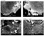
- FIG. 2 is a photograph in which a cross section of the denitration catalyst composition of the present invention is analyzed by SEM and compared with a cross section of a conventional denitration catalyst composition.
- FIG. 3 is a graph showing the result of analyzing the CeO 2 loading position by measuring the pore distribution and NO purification rate of the denitration catalyst composition of the present invention.
- FIG. 4 is a chart (B) showing the conditions (A) for evaluating the denitration performance in an atmosphere in which the oxygen concentration varies using the denitration catalyst composition of the present invention, and the evaluation results.
- the denitration catalyst composition of the present invention and the denitration method using the same will be described in detail.
- the present invention is not limited to automobile applications, and can be widely applied to a denitration technique for nitrogen oxides in exhaust gas.
- Denitration catalyst composition The denitration catalyst composition of the present invention comprises rhodium (Rh) as an essential component on a zirconium oxide carrier (A) formed by agglomeration or mixing of primary particles mainly composed of zirconium oxide.
- the noble metal element (C) is supported, and the cerium-containing oxide (B) is present on the surface of the zirconium oxide-based support (A) and in the gaps between the secondary particles.
- the denitration catalyst composition of the present invention comprises a catalytically active component, a cocatalyst component and a carrier for supporting the same, and uses a zirconium oxide-based carrier (A) as the carrier.
- the raw material powder of the zirconium oxide support is a known material, for example, obtained by pulverizing oxide particles obtained by firing at least one inorganic or organic zirconium compound at 450 to 600 ° C. in the atmosphere. .
- the zirconium oxide-based support (A) may be a single component oxide of zirconium, but may be a composite oxide with a rare earth composite oxide or the like. It is preferable to contain 1 to 30% by weight of one or more rare earth elements selected from La, Nd, Pr, Fe or Y as an oxide.
- gadolinium oxide / zirconia composite oxide gadolinium oxide / zirconia composite oxide, neodymium oxide / zirconia composite oxide, zirconia / praseodymium oxide composite oxide, zirconia / lanthanum oxide composite oxide, neodymium oxide / zirconia oxide composite, zirconia / lanthanum oxide / oxide
- examples include samarium composite oxide, zirconia / terbium oxide composite oxide, and the like.
- the reference weight ratio of zirconia to other oxides in the solid solution is in the range of 95 to 70: 5 to 30, preferably 90 to 75:10 to 25.
- the particles of the zirconium oxide carrier (A) are not limited by the particle size, but for example, an average particle size of 1 to 50 ⁇ m is preferable.
- the pores of the zirconium oxide carrier (A) are preferably composed of pores composed of primary particles of 5 to 100 nm and pores composed of secondary particles of 0.2 to 10 ⁇ m. With such pores, the following noble metal element (C) can be supported, and the cerium-containing oxide (B) can be present in the surface and the secondary particle gap in a specific state.
- rhodium is contained as an essential component as a noble metal element. Rhodium can significantly improve the denitration performance when used together with the cerium-containing oxide (B) as a promoter.
- the noble metal element platinum, palladium, gold, silver and the like can be contained in addition to rhodium. If platinum or palladium is used, the purification performance of hydrocarbons contained in the exhaust gas is further improved, and catalyst poisoning is further suppressed. For example, by using rhodium and palladium in combination, the denitration performance of rhodium can be further improved.
- the content of the noble metal element (C) is 0.01 to 10% by weight, preferably 0.1 to 5% by weight, and 0.5 to 3.0% by weight with respect to the zirconium oxide carrier (A). % Is more preferable. By setting the content within this range, excellent denitration performance is exhibited.
- transition metals such as nickel, cobalt, zirconium, copper, and iron, and rare earth metals such as lanthanum, praseodymium, and neodymium.
- Cerium-containing oxide (B) The catalyst in which rhodium is supported on the zirconia support (A), that is, Rh / ZrO 2 , can improve the NOx purification efficiency by the steam reforming reaction. However, the CO—O 2 reaction proceeds predominantly in the presence of oxygen, and the selectivity of the CO—NO reaction is low. Therefore, this is not sufficient as a denitration catalyst, and a catalyst for reducing oxygen from Rh / ZrO 2 Powder is required. Therefore, the denitration catalyst composition of the present invention contains a cerium-containing oxide (B) in addition to the noble metal element (C) containing rhodium supported on the zirconium oxide-based support (A) as an essential component.
- CeO 2 material can absorb and release oxygen as shown in the following formula (3) according to the atmosphere of oxidation and reduction, and its function as an OSC that absorbs and releases oxygen in the bulk is well known. ing. By using this reaction to oxidize CO, HC and soluble organic components, these harmful components can be purified. 2CeO 2 ⁇ Ce 2 O 3 + O 2 (3) However, not the OSC function but the function of CeO 2 as a denitration catalyst in the CO—NO reaction in the presence of oxygen is hardly known.
- the present invention elucidates the function as a denitration catalyst, and when Ce is in a state of CeO 2 saturated with oxygen, the substitution rate of atmospheric oxygen and oxygen on the surface of the oxide is changed to ZrO 2 material or Al 2 O. It uses the characteristic that it is overwhelmingly faster than the three materials.
- the present invention pays attention to the surface oxygen exchange properties of various oxides, and has a structure in which fine particles of CeO 2 are adjacent to the periphery of the secondary particles of Rh / ZrO 2 in order to control the oxygen concentration.
- FIG. 1 shows the structure of the denitration catalyst composition of the present invention and the denitration reaction mechanism in a carbon monoxide and oxygen atmosphere.
- CeO 2 with Rh is because it is supported on ZrO 2 carrier, from ZrO 2 surface to CeO 2, is formed further flow of O 2 to be released into the atmosphere from CeO 2, Rh / ZrO 2 It is thought that the upper surface oxygen concentration can be reduced.
- cerium-containing oxide in addition to cerium oxide (ceria), powder particles such as cerium-transition metal composite oxide and cerium-rare earth composite oxide can be used. That is, the cerium-containing oxide (B) is a single phase of cerium oxide, or one or more rare earth elements selected from La, Nd, Pr, Y, Fe, or Zr, or a transition metal element as an oxide. It can contain 50 weight% or less.
- the cerium-containing oxide (B) preferably contains 1 to 50% by weight of an oxide of one or more rare earth elements selected from La, Nd, Pr, Y, Fe or Zr, or a transition metal element. More preferably, it is ⁇ 45% by weight.
- cerium oxide (ceria) and zirconium oxide (zirconia) or the like are not merely physically mixed, but can be regarded as one oxide chemically bonded to each other with an oxygen atom in the lattice.
- FIG. 2 is a photograph obtained by analyzing a cross section of the denitration catalyst composition by SEM.
- the cerium-containing oxide (B) is a primary particle of zirconium oxide-based support (A). Exist between.
- the cerium-containing oxide (B) is present on the surface of the zirconium oxide-based support (A) and in the gaps between the secondary particles. Yes. Note that the lower right part of FIG.
- FIG. 2 the pore distribution and NO purification rate of NO x removal catalyst compositions of the present invention was measured, it shows the results of analysis of the carrying position of CeO 2, whereby CeO 2 is between the primary particles It can be seen that high NO purification characteristics can be obtained when it is hardly supported on (less than 100 nm) and mainly exists between secondary particles (100 to 1000 nm). In the present invention, the existence probability of CeO 2 between secondary particles (100 to 1000 nm) is desirably 50% or more.
- the existence probability is preferably 60% or more, more preferably 70% or more, and still more preferably 80% or more.
- Rh / ZrO 2 and CeO 2 have an appropriate distance interval.
- the distance between the reaction field Rh / ZrO 2 particles and the CeO 2 particles having an oxygen diffusivity control function is increased, for example, 20 ⁇ m, it is confirmed that the NO purification performance improvement effect due to the addition of CeO 2 tends to decrease. Has been.
- a major feature of the present invention is that after heat treatment at a high temperature during catalyst preparation, a unique catalyst structure having a zirconium oxide phase, a cerium oxide phase, and its interface is formed while suppressing solid solution of zirconium oxide and cerium oxide.
- This unique catalyst structure provides an effective denitration action.
- the particle diameter of the cerium-containing oxide (B) is preferably 5 nm to 20 ⁇ m, more preferably 10 nm to 2 ⁇ m. This enables the cerium-containing oxide (B) to be present on the surface of the zirconium oxide-based support (A) and the gap between the secondary particles.
- the particle size of the cerium-containing oxide (B) When the particle size of the cerium-containing oxide (B) is small and less than 5 nm, it penetrates into the pores (5 to 100 nm) between the primary particles of the zirconium oxide support (A), while the particle size is large and about 10 nm. If so, it is presumed that they are unlikely to exist in the pores between the primary particles of the zirconium oxide carrier (A) and are selectively present in the gaps between the secondary particles.
- the cerium-containing oxide (B) is preferably composed mainly of a single phase of cerium oxide after heat treatment at 1000 ° C., and may exist in the form of a solid solution (mixed oxide) with zirconium oxide.
- the content of is preferably 60% or more, more preferably 70% or more, and still more preferably 80% or more. Since the cerium-containing oxide (B) is mainly composed of a single phase of cerium oxide, the effect of reducing the oxygen concentration from Rh / ZrO 2 is improved. On the other hand, if the solid solution with zirconium oxide increases and the content of the single phase is less than 60%, the denitration performance may be deteriorated, which is not preferable.
- the solid solubility of the cerium-containing oxide (B) in the zirconium oxide-based carrier (A) is preferably 50% or less, and more preferably 40% or less.
- the solid solubility of the cerium-containing oxide (B) in the zirconium oxide-based support (A) is specifically defined by the following formula (4).
- Solid solubility (%) 100 ⁇ (CeO 2 concentration was dissolved in ZrO 2) / ⁇ total CeO 2 concentration of (ZrO 2 + CeO 2) in ⁇ (4)
- the solid solubility of the cerium-containing oxide (B) in the zirconium oxide-based support (A) is based on the peak position of the (220) plane of ZrO 2 and CeO 2 obtained from XRD measurement. From this, it is calculated from the peak shift width of the actual sample.
- the cerium-containing oxide (B) is not limited by its content, but is preferably 1 to 50% by weight, more preferably 1 to 30% by weight with respect to the zirconium oxide-based support (A). 20% by weight is more preferable, and 1 to 10% by weight is most preferable. Within this range, excellent denitration performance can be obtained.
- the catalyst composition of the present invention can be expected to have a desired denitration performance only with the above-mentioned components, but can contain composite oxides such as alumina and silica-alumina having high heat resistance, if necessary.
- alumina include ⁇ -alumina and ⁇ -alumina.
- composite oxides include composite oxides containing alumina such as silica-alumina-zirconia and silica-alumina-boria.
- the denitration catalyst composition of this invention is not limited by a manufacturing method, For example, it can manufacture by the following methods.
- an aqueous solution containing a noble metal element (C) containing rhodium (Rh) as an essential component is water-absorbed on a raw material powder having an average particle diameter of 1 to 50 ⁇ m mainly composed of zirconium oxide.
- a catalyst powder in which the noble metal element (C) is supported on the zirconium oxide carrier (A) is prepared (hereinafter also referred to as the first step).
- the raw material powder of the cerium-containing oxide (B) having an average particle size of 0.1 to 20 ⁇ m is mixed, and pulverized as necessary to adjust the particle size, and the secondary particle surface of the zirconium oxide carrier (A)
- the cerium-containing oxide (B) is dispersed and supported in the gaps between the secondary particles and, if necessary, molded, and then calcined at 500 ° C. for 0.5 to 1 hour in an oxygen-containing atmosphere (hereinafter referred to as “first”). Also called the second step).
- an average particle size of 5 to 20 nm is used instead of the second step.
- the cerium-containing oxide raw material sol is mixed at a pH of 2 to 9, and the cerium-containing oxide (B) is selectively dispersed and supported on the surface of the zirconium oxide carrier (A) and in the gaps between the secondary particles. After molding, if necessary, it can be fired at 500 ° C. for 0.5 to 1 hour in an oxygen-containing atmosphere.
- the second step is performed. Instead, an aqueous solution of a cerium-containing compound is mixed, and the cerium-containing oxide (B) is selectively dispersed and supported on the surface of the zirconium oxide carrier (A) and in the gaps between the secondary particles, and is molded as necessary. Thereafter, it can also be produced by baking at 500 ° C. for 0.5 to 1 hour in an oxygen-containing atmosphere.
- the denitration catalyst composition of the present invention can be used as a structural catalyst in which the above catalyst components are coated on various carrier surfaces.
- the shape of the carrier is not particularly limited, and can be selected from a prismatic shape, a cylindrical shape, a spherical shape, a honeycomb shape, a sheet shape, and the like, and a honeycomb structure carrier is preferable.
- the size of the structure-type carrier is not particularly limited, and a structural carrier having a diameter (length) of several millimeters to several centimeters can be used as long as it is any of a prismatic shape, a cylindrical shape, and a spherical shape.
- the honeycomb structure carrier is made of a ceramic such as cordierite, silicon carbide, silicon nitride, or a metal such as stainless steel, and has a large number of parallel fine gas passages extending throughout the structure carrier. Is. Of these, cordierite is preferred as the material because of durability and cost. Further, for such a honeycomb structure carrier, an appropriate number of holes is determined in consideration of the type of exhaust gas to be processed, gas flow rate, pressure loss, removal efficiency, etc. with respect to the number of holes in the opening.
- the cell density is preferably 100 to 900 cells / inch 2 , and more preferably 200 to 600 cells / inch 2 .
- the cell density is the number of cells per unit area in a cross section when the honeycomb structure carrier is cut at right angles to the gas flow path.
- the honeycomb structure carrier has a flow-through structure in which the gas flow path communicates with a part of the end face of the gas flow path, and gas can flow through the wall surface of the gas flow path.
- a wall flow structure is widely known.
- the flow-through type structure has low air resistance and can reduce the pressure loss of the exhaust gas, and the wall flow type structure filters out particulate components contained in the exhaust gas. It is possible.
- the denitration catalyst composition of the present invention can be used for either structure.
- the monolithic denitration catalyst of the present invention is prepared by mixing the denitration catalyst composition and, if necessary, a binder or the like with an aqueous medium to form a slurry mixture, and then coating the monolithic support carrier for drying and firing. It is manufactured by doing.
- a denitration catalyst composition and an aqueous medium are mixed at a predetermined ratio to obtain a slurry mixture.
- the aqueous medium may be used in such an amount that the denitration catalyst composition can be uniformly dispersed in the slurry.
- an acid or an alkali for adjusting the pH can be blended, or a surfactant, a dispersing resin or the like can be blended for adjusting the viscosity or improving the slurry dispersibility.
- pulverization and mixing by a ball mill or the like can be applied, but other pulverization or mixing methods may be applied.
- the denitration catalyst composition of the present invention is preferably coated on such a honeycomb structure carrier at a loading of 50 to 350 g / L, more preferably 80 to 250 g / L.
- drying and baking are performed to obtain a monolithic denitration catalyst carrying a catalyst composition.
- the drying temperature is preferably from 100 to 300 ° C, more preferably from 100 to 200 ° C.
- the firing temperature is preferably 300 to 700 ° C, and preferably 400 to 600 ° C.
- a heating means it can carry out by well-known heating means, such as an electric furnace and a gas furnace.
- Denitration Method In the denitration method of the present invention, exhaust gas containing NO (nitrogen oxide), CO (carbon monoxide), and O 2 (oxygen) is oxidized with an air / fuel ratio (A / F) of 14.7 or more.
- the denitration catalyst composition is brought into contact with the denitration catalyst composition in a temperature range of 350 to 800 ° C. in a wide range including a general atmosphere.
- the exhaust gas flow rate and the exhaust gas temperature vary depending on the driving conditions, but the space velocity is approximately 40000-200000 / hr, and the exhaust gas temperature is approximately 300-1000 ° C.
- the air / fuel ratio (A / F) constantly fluctuates due to on / off of the accelerator, braking, shift change, etc., and Lean with insufficient fuel based on the stoichiometric air-fuel ratio of 14.7. There is Rich's condition with excessive fuel.
- the denitration method of the present invention can exhibit purification performance in such a space velocity region and temperature region even in a lean state where the NO purification reaction is particularly difficult to progress up to 20.
- (1) XRD measurement The powder samples obtained in the examples and comparative examples were measured for diffraction patterns using an X-ray diffractometer and collated with ICSD card data to identify catalyst components. Measurement was performed using a semiconductor detector under the conditions of 45 kV-40 mA, Step Size 0.0167 s, and Scan Speed 0.107815 ° / s. Peak separation by a Gaussian function was performed from the obtained diffraction pattern, and a peak position and a half width were determined. Further, the solid solubility of CeO 2 with the ZrO 2 base material is calculated from the peak position of the ZrO 2 (220) surface from the peak shift width, and the crystallite diameter of CeO 2 is calculated from the half width using Scherrer's equation. Calculated.
- Pore distribution measurement After 0.3 g of various powder samples were dried, the pore distribution of the catalyst sample was measured by the Hg intrusion measurement method. Compared with the CeO 2 non-added sample, the loading position of the added CeO 2 was estimated from the decrease rate of the pore volume.
- Example 1 First, 10% Nd 2 O 3 -10% La 2 O 3 -80% ZrO 2 composite oxide powder having a BET of 40 to 70 m 2 / g and an average pore diameter of 10 to 50 nm was prepared as a carrier. Next, 9.45 g of the carrier was impregnated with an aqueous solution obtained by diluting 0.68 g of a 7.35 wt% rhodium nitrate aqueous solution (corresponding to Rh 0.05 g) with 2.0 g of water.
- aqueous solution obtained by diluting 0.68 g of a 7.35 wt% rhodium nitrate aqueous solution (corresponding to Rh 0.05 g) with 2.0 g of water.
- This hydrous powder was then impregnated and supported with 3.29 g of CeO 2 sol aqueous solution (corresponding to 0.50 g of CeO 2 ) having a pH of 2 to 3, a sol diameter of 5 to 30 nm, a CeO 2 concentration of 15%, and a ⁇ potential of +.
- baking was performed at 500 ° C. for 1 hour.
- the powder catalyst 4.0g after baking was put into the alumina crucible, and it heat-processed in Air at 1000 degreeC for 6 hours in the electric furnace.
- the composition of the denitration catalyst composition of the present invention is shown in Table 1, and a photograph obtained by analyzing the cross section of this denitration catalyst composition with SEM is shown in the lower part of FIG.
- the denitration catalyst composition of the present invention exhibits excellent denitration performance in a Lean (A / F 13.6-17) atmosphere in which oxygen is excessive from the vicinity of stoichio.
- Example 2 Instead of the CeO 2 sol solution of Example 1, 4.27 g of CeO 2 sol aqueous solution (corresponding to 0.50 g of CeO 2 ) having a pH of 7 to 9, a sol diameter of 10 to 30 nm, a CeO 2 concentration of 12%, and a ⁇ potential ⁇ was used. .
- Table 1 shows the composition of the denitration catalyst composition of the present invention.
- a catalyst performance test was conducted in the same manner as in Example 1. As a result, it was confirmed that the denitration catalyst composition of the present invention exhibits excellent denitration performance in a Lean (A / F 13.6 to 17) atmosphere in which oxygen is excessive from the vicinity of stoichio, as shown in FIG. did it.
- Example 3 As in Example 1, ZrO 2 powder impregnated with an aqueous rhodium nitrate solution was impregnated with 2.0 g of 28% aqueous ammonia, followed by 1.71 g of 29.20% aqueous cerium nitrate solution (corresponding to 0.5 g of CeO 2 ). Additional impregnation was carried. Thereafter, the same aging and baking treatment was performed.
- the composition of the denitration catalyst composition of the present invention is shown in Table 1, and a photograph obtained by analyzing the cross section of this denitration catalyst composition with SEM is shown in FIG. 2 (upper right side). Next, a catalyst performance test was conducted in the same manner as in Example 1.
- the denitration catalyst composition of the present invention exhibits excellent denitration performance in a Lean (A / F 13.6 to 17) atmosphere in which oxygen is excessive from the vicinity of stoichio, as shown in FIG. did it.
- Example 4 In the same manner as in Example 1, ZrO 2 powder impregnated with an aqueous rhodium nitrate solution was baked to prepare Rh-supported ZrO 2 powder.
- a slurry was prepared so as to be 0 ⁇ m. 100 g of the slurry was placed in an evaporating dish, evaporated to dryness for 30 minutes while stirring on a hot plate heated to 150 ° C., further dried overnight in a dryer at 80 ° C., and baked at 500 ° C.
- Table 1 shows the composition of the denitration catalyst composition of the present invention.
- a catalyst performance test was conducted in the same manner as in Example 1. As a result, it was confirmed that the denitration catalyst composition of the present invention exhibits excellent denitration performance in a Lean (A / F 13.6 to 17) atmosphere in which oxygen is excessive from the vicinity of stoichio, as shown in FIG. did it.
- Example 5 The denitration of the present invention shown in Table 1 is similarly performed except that the Rh / ZrO 2 powder and CeO 2 powder of Example 4 are similarly pulverized and mixed using an agate mortar so that the 50% particle size is 20 ⁇ m. A catalyst composition was prepared. Next, a catalyst performance test was conducted in the same manner as in Example 1. As shown in FIG. 4, this denitration catalyst composition has slightly lower denitration performance than Lean (A / F 15.3 to 17) atmosphere in excess of oxygen as compared with Example 1, but there is a problem in practical use. Absent.
- Example 1 A comparative denitration catalyst composition shown in Table 1 was similarly prepared except that the CeO 2 sol aqueous solution used in Example 1 was not added and the rhodium nitrate-impregnated ZrO 2 powder was calcined. Moreover, the photograph which analyzed the cross section of this denitration catalyst composition by SEM is shown in FIG. 2 (upper left side). Next, a catalyst performance test was conducted in the same manner as in Example 1. As shown in FIG. 4, it was confirmed that this denitration catalyst composition had lower denitration performance compared to Example 1 in the Lean (A / F 13.6 to 17) atmosphere in which oxygen was excessive from the vicinity of stoichiometric. .
- Comparative Example 2 A comparative denitration catalyst composition shown in Table 1 was similarly prepared except that 1.71 g of a 29.2% cerium nitrate aqueous solution was used instead of the CeO 2 sol aqueous solution of Example 1. Next, a catalyst performance test was conducted in the same manner as in Example 1. As shown in FIG. 4, it was confirmed that this denitration catalyst composition had lower denitration performance compared to Example 1 in the Lean (A / F 13.6 to 17) atmosphere in which oxygen was excessive from the vicinity of stoichiometric. .
- Example 3 The denitration catalyst for comparison shown in Table 1 is similarly used except that the addition order of the aqueous ammonia and the aqueous cerium nitrate solution in Example 3 is reversed and cerium nitrate and ammonia water are added in this order to the rhodium nitrate-impregnated ZrO 2 powder. A composition was prepared. Next, a catalyst performance test was conducted in the same manner as in Example 1. As shown in FIG. 4, it was confirmed that this denitration catalyst composition had lower denitration performance than Example 1 in a Lean (A / F 15.3 to 17) atmosphere containing excess oxygen.
- Example 4 The Rh / ZrO 2 powder and the CeO 2 powder of Example 4 were used in the same manner except that the Rh / ZrO 2 powder and the CeO 2 powder were pulverized and mixed using a bead mill so that the 50% particle size was 0.2 ⁇ m. A denitration catalyst composition was prepared. Next, a catalyst performance test was conducted in the same manner as in Example 1. As shown in FIG. 4, it was confirmed that this denitration catalyst composition had lower denitration performance than Example 1 in a Lean (A / F 15.3 to 17) atmosphere containing excess oxygen.
- the catalyst of the example has a higher NO purification rate than the comparative example, and the selectivity of the CO—NO reaction is improved.
- the NO purification performance greatly depended on the state of CeO 2 after heat treatment at 1000 ° C.
- the concentration of CeO 2 added during heat treatment at 1000 ° C. in the ZrO 2 matrix is low (40% or less), and the catalyst structure maintaining both the CeO 2 phase and the ZrO 2 phase has an oxygen concentration in the vicinity of the active site. It is considered that high CO-NO reactivity was exhibited.
- the denitration catalyst composition of the present invention can be preferably applied to a denitration device for nitrogen oxides in exhaust gas in gasoline and diesel automobiles, but is widely used for denitration technology for nitrogen oxides in exhaust gas such as boilers and other fixed emission sources. Applicable.
Abstract
Description
排出ガス全体のうち、自動車の排出ガスによる発生量が3割を占めている。微量の窒素酸化物は植物の生育に役立つが、濃度が高いと大気汚染、光化学スモッグ、酸性雨の原因となることから、自動車では圧縮比や燃焼温度を低くするエンジン制御を行い、発生を抑制している。 Nitrogen oxide is generated in a very small amount in normal combustion, but nitrogen is easily oxidized in a combustion chamber that is in a high temperature and high pressure state, and the generation amount is increased. In recent years when the compression ratio has become higher on average for improving combustion efficiency, the emission amount has reached a level that cannot be ignored.
Of the total exhaust gas, 30% is generated by automobile exhaust gas. Trace amounts of nitrogen oxides are useful for plant growth, but high concentrations cause air pollution, photochemical smog, and acid rain. Therefore, in automobiles, engine control is performed to reduce the compression ratio and combustion temperature to suppress generation. is doing.
CO+NO→CO2+N2 ・・・(1)
2CO+O2→2CO2 ・・・(2)
なお、化学量論雰囲気においては、600℃を超えると式(2)の反応が支配的となり、600℃以下では式(1)(2)の反応が競争的に進行すること、その選択率は貴金属元素の周囲の酸素濃度に依存することも知られている(非特許文献1)。しかしながら、酸素共存下でのCO-NO反応では、このようにCO-O2反応が競争的に進行するため、公知の触媒ではCO-NO反応が進行しにくい事象が確認されている。 On the other hand, in purification using automobile catalysts for gasoline vehicles (three-way catalysts), in addition to NO reduction reaction via reaction in rich atmosphere typified by steam reforming reaction and water gas shift reaction, lean oxygen concentration is slightly high Also in the region, the CO—NO reaction, which is one of the important elementary reactions for reducing NO, can be mentioned. The CO-NO reaction is a process in which NO is reduced by using a large amount of CO present in the exhaust gas of an automobile, and the reaction proceeds as shown in the following formula (1).
CO + NO → CO 2 + N 2 (1)
2CO + O 2 → 2CO 2 (2)
In the stoichiometric atmosphere, when the temperature exceeds 600 ° C., the reaction of the formula (2) becomes dominant, and when the temperature is 600 ° C. or less, the reactions of the formulas (1) and (2) proceed competitively. It is also known that it depends on the oxygen concentration around the noble metal element (Non-patent Document 1). However, in the CO—NO reaction in the presence of oxygen, since the CO—O 2 reaction proceeds competitively in this way, it has been confirmed that the CO—NO reaction does not easily proceed with known catalysts.
また、本発明の第3の発明によれば、第1の発明において、酸化ジルコニウム系担体(A)の細孔が、5~100nmの一次粒子で構成される細孔と0.2~10μmの二次粒子で形成される細孔から構成されることを特徴とする脱硝触媒組成物が提供される。
また、本発明の第4の発明によれば、第1の発明において、セリウム含有酸化物(B)の粒径が、0.005(5nm)~20μmであることを特徴とする脱硝触媒組成物が提供される。 According to the second invention of the present invention, in the first invention, the zirconium oxide carrier (A) is one or more rare earth elements selected from La, Nd, Pr, Fe or Y, or a transition metal. A denitration catalyst composition comprising 1 to 30% by weight of an element as an oxide is provided.
According to the third aspect of the present invention, in the first aspect, the zirconium oxide-based support (A) has pores composed of primary particles of 5 to 100 nm and 0.2 to 10 μm. There is provided a denitration catalyst composition comprising pores formed of secondary particles.
According to a fourth aspect of the present invention, there is provided a denitration catalyst composition according to the first aspect, wherein the cerium-containing oxide (B) has a particle size of 0.005 (5 nm) to 20 μm. Is provided.
また、本発明の第6の発明によれば、第1の発明において、セリウム含有酸化物(B)が、酸化セリウムの単一相であるか、La、Nd、Pr、Y、Fe又はZrから選ばれる1種以上の希土類元素、若しくは遷移金属元素を酸化物として50重量%以下含有することを特徴とする脱硝触媒組成物が提供される。
また、本発明の第7の発明によれば、第1の発明において、セリウム含有酸化物(B)の酸化ジルコニウム系担体(A)への固溶度が、50%以下であることを特徴とする脱硝触媒組成物が提供される。
また、本発明の第8の発明によれば、第1の発明において、セリウム含有酸化物(B)の含有量が、酸化ジルコニウム系担体(A)に対して、1~50重量%であることを特徴とする脱硝触媒組成物が提供される。 According to the fifth aspect of the present invention, there is provided a denitration catalyst composition according to the first aspect, wherein the crystallite diameter of the cerium-containing oxide (B) is 8 to 50 nm. .
According to the sixth invention of the present invention, in the first invention, the cerium-containing oxide (B) is a single phase of cerium oxide, or from La, Nd, Pr, Y, Fe, or Zr. A denitration catalyst composition comprising one or more selected rare earth elements or transition metal elements as oxides in an amount of 50% by weight or less is provided.
According to a seventh aspect of the present invention, in the first aspect, the solid solubility of the cerium-containing oxide (B) in the zirconium oxide-based support (A) is 50% or less. A denitration catalyst composition is provided.
According to the eighth aspect of the present invention, in the first aspect, the content of the cerium-containing oxide (B) is 1 to 50% by weight with respect to the zirconium oxide-based support (A). A denitration catalyst composition is provided.
また、本発明の第10の発明によれば、第1の発明において、貴金属元素(C)の含有量が、酸化ジルコニウム系担体(A)に対して、0.01~10重量%であることを特徴とする脱硝触媒組成物が提供される。 Furthermore, according to the ninth aspect of the present invention, there is provided a denitration catalyst composition characterized in that, in the first aspect, the noble metal element (C) has a particle size of 1 to 5 nm.
According to the tenth aspect of the present invention, in the first aspect, the content of the noble metal element (C) is 0.01 to 10% by weight with respect to the zirconium oxide-based support (A). A denitration catalyst composition is provided.
さらに、本発明の脱硝触媒組成物は、高価な活性金属の使用量が少なくて済むため低コストで製造する事ができ、排気ガス浄化装置を安定的に生産し供給することができる。 The denitration catalyst composition of the present invention is excellent in nitrogen oxide reduction activity and exhibits high purification performance for nitrogen oxides discharged from various combustion apparatuses. In particular, the selectivity of the NO—CO reaction in the presence of oxygen is improved, and the purification performance of nitrogen oxides is greatly improved in the temperature range of 400 to 800 ° C. even if the oxygen concentration in the exhaust gas varies. It is very effective in purifying nitrogen oxides emitted from gasoline and diesel engines.
Furthermore, the denitration catalyst composition of the present invention can be manufactured at low cost because the amount of expensive active metal used is small, and an exhaust gas purification device can be stably produced and supplied.
本発明の脱硝触媒組成物は、酸化ジルコニウムを主成分とする一次粒子が凝集または混合して形成された酸化ジルコニウム系担体(A)上に、ロジウム(Rh)を必須成分とする貴金属元素(C)が担持され、さらにセリウム含有酸化物(B)が酸化ジルコニウム系担体(A)の表面、及び二次粒子の間隙に存在することを特徴とする。 1. Denitration catalyst composition The denitration catalyst composition of the present invention comprises rhodium (Rh) as an essential component on a zirconium oxide carrier (A) formed by agglomeration or mixing of primary particles mainly composed of zirconium oxide. The noble metal element (C) is supported, and the cerium-containing oxide (B) is present on the surface of the zirconium oxide-based support (A) and in the gaps between the secondary particles.
本発明の脱硝触媒組成物は、触媒活性成分、助触媒成分とそれを担持する担体からなり、担体として酸化ジルコニウム系担体(A)を使用する。 (1) Zirconium oxide carrier (A)
The denitration catalyst composition of the present invention comprises a catalytically active component, a cocatalyst component and a carrier for supporting the same, and uses a zirconium oxide-based carrier (A) as the carrier.
すなわち、例えば、酸化ガドリニウム/ジルコニア複合酸化物、酸化ネオジム/ジルコニア複合酸化物、ジルコニア/酸化プラセオジム複合酸化物、ジルコニア/酸化ランタン複合酸化物、酸化ネオジム/ジルコニア複合酸化物、ジルコニア/酸化ランタン/酸化サマリウム複合酸化物、ジルコニア/酸化テルビウム複合酸化物等が挙げられる。この場合、固溶体におけるジルコニアと他の酸化物との基準重量比は、95~70:5~30、好ましくは、90~75:10~25の範囲である。 The zirconium oxide-based support (A) may be a single component oxide of zirconium, but may be a composite oxide with a rare earth composite oxide or the like. It is preferable to contain 1 to 30% by weight of one or more rare earth elements selected from La, Nd, Pr, Fe or Y as an oxide.
That is, for example, gadolinium oxide / zirconia composite oxide, neodymium oxide / zirconia composite oxide, zirconia / praseodymium oxide composite oxide, zirconia / lanthanum oxide composite oxide, neodymium oxide / zirconia oxide composite, zirconia / lanthanum oxide / oxide Examples include samarium composite oxide, zirconia / terbium oxide composite oxide, and the like. In this case, the reference weight ratio of zirconia to other oxides in the solid solution is in the range of 95 to 70: 5 to 30, preferably 90 to 75:10 to 25.
また、酸化ジルコニウム系担体(A)の細孔が、5~100nmの一次粒子で構成される細孔と0.2~10μmの二次粒子で形成される細孔から構成されることが好ましい。このような細孔であれば、下記の貴金属元素(C)を担持し、セリウム含有酸化物(B)を特定の状態で表面および2次粒子間隙に存在させることができる。 The particles of the zirconium oxide carrier (A) are not limited by the particle size, but for example, an average particle size of 1 to 50 μm is preferable.
The pores of the zirconium oxide carrier (A) are preferably composed of pores composed of primary particles of 5 to 100 nm and pores composed of secondary particles of 0.2 to 10 μm. With such pores, the following noble metal element (C) can be supported, and the cerium-containing oxide (B) can be present in the surface and the secondary particle gap in a specific state.
本発明においては、貴金属元素として、ロジウムを必須成分として含有する。ロジウムは、助触媒のセリウム含有酸化物(B)との併用により脱硝性能を大幅に向上することができる。貴金属元素としては、ロジウムのほかに白金、パラジウム、金、銀などを含有することができる。白金、またはパラジウムを用いれば排気ガスに含まれる炭化水素の浄化性能がより向上し、触媒被毒もより抑制される。例えば、ロジウムとパラジウムを併用することでロジウムの脱硝性能をさらに向上させることができる。 (2) Noble metal element (C)
In the present invention, rhodium is contained as an essential component as a noble metal element. Rhodium can significantly improve the denitration performance when used together with the cerium-containing oxide (B) as a promoter. As the noble metal element, platinum, palladium, gold, silver and the like can be contained in addition to rhodium. If platinum or palladium is used, the purification performance of hydrocarbons contained in the exhaust gas is further improved, and catalyst poisoning is further suppressed. For example, by using rhodium and palladium in combination, the denitration performance of rhodium can be further improved.
上記ジルコニア担体(A)にロジウムが担持された触媒、すなわちRh/ZrO2は、スチームリフォーミング反応によりNOxの浄化効率を向上することができる。しかしながら、酸素共存下ではCO-O2反応が支配的に進行し、CO-NO反応の選択性が低いため、このままでは脱硝触媒として十分ではなく、Rh/ZrO2から酸素を低減させるための触媒粉末が必要である。
そのため本発明の脱硝触媒組成物においては、上記酸化ジルコニウム系担体(A)に担持されるロジウムを必須成分とする貴金属元素(C)のほかに、セリウム含有酸化物(B)を含有する。 (3) Cerium-containing oxide (B)
The catalyst in which rhodium is supported on the zirconia support (A), that is, Rh / ZrO 2 , can improve the NOx purification efficiency by the steam reforming reaction. However, the CO—O 2 reaction proceeds predominantly in the presence of oxygen, and the selectivity of the CO—NO reaction is low. Therefore, this is not sufficient as a denitration catalyst, and a catalyst for reducing oxygen from Rh / ZrO 2 Powder is required.
Therefore, the denitration catalyst composition of the present invention contains a cerium-containing oxide (B) in addition to the noble metal element (C) containing rhodium supported on the zirconium oxide-based support (A) as an essential component.
2CeO2⇔Ce2O3+O2 ・・・(3)
しかしながら、OSC機能ではなく、酸素共存下でのCO-NO反応における脱硝触媒としてのCeO2の機能は殆ど知られていない。本発明は、脱硝触媒としての機能を解明して、Ceが酸素で飽和されているCeO2の状態であると、大気酸素と酸化物表面の酸素の置換速度が、ZrO2材料やAl2O3材料に比べて圧倒的に速いという特性を利用するものである。 Until now, CeO 2 material can absorb and release oxygen as shown in the following formula (3) according to the atmosphere of oxidation and reduction, and its function as an OSC that absorbs and releases oxygen in the bulk is well known. ing. By using this reaction to oxidize CO, HC and soluble organic components, these harmful components can be purified.
2CeO 2 ⇔Ce 2 O 3 + O 2 (3)
However, not the OSC function but the function of CeO 2 as a denitration catalyst in the CO—NO reaction in the presence of oxygen is hardly known. The present invention elucidates the function as a denitration catalyst, and when Ce is in a state of CeO 2 saturated with oxygen, the substitution rate of atmospheric oxygen and oxygen on the surface of the oxide is changed to ZrO 2 material or Al 2 O. It uses the characteristic that it is overwhelmingly faster than the three materials.
図1には、本発明の脱硝触媒組成物の構造と、一酸化炭素、酸素雰囲気下での脱硝反応メカニズムを示している。CeO2がZrO2担体に担持されていない場合は、CO-NO反応において、Rhの表面で、NOがCOと反応してCO2とN2になるが、これと同時にRh上で解離した酸素がCOと反応してCO2が生成する。ところが、本触媒では、RhとともにCeO2がZrO2担体に担持されているので、ZrO2表面からCeO2へ、さらにCeO2から大気に放出されるO2の流れが形成され、Rh/ZrO2上の表面酸素濃度を低減できるものと考えられる。 The present invention pays attention to the surface oxygen exchange properties of various oxides, and has a structure in which fine particles of CeO 2 are adjacent to the periphery of the secondary particles of Rh / ZrO 2 in order to control the oxygen concentration. As a result, the oxygen concentration in the vicinity of the catalyst active point decreases, the CO—O 2 reaction is suppressed, and the CO—NO reaction is promoted.
FIG. 1 shows the structure of the denitration catalyst composition of the present invention and the denitration reaction mechanism in a carbon monoxide and oxygen atmosphere. When CeO 2 is not supported on the ZrO 2 carrier, in the CO—NO reaction, NO reacts with CO on the surface of Rh to become CO 2 and N 2. At the same time, oxygen dissociated on Rh Reacts with CO to produce CO 2 . However, in the present catalyst, CeO 2 with Rh is because it is supported on ZrO 2 carrier, from ZrO 2 surface to CeO 2, is formed further flow of O 2 to be released into the atmosphere from CeO 2, Rh / ZrO 2 It is thought that the upper surface oxygen concentration can be reduced.
セリウム含有酸化物(B)が、La、Nd、Pr、Y、Fe又はZrから選ばれる1種以上の希土類元素、若しくは遷移金属元素を酸化物として1~50重量%含有することが好ましく、3~45重量%であることがより好ましい。
複合酸化物において、酸化セリウム(セリア)と酸化ジルコニウム(ジルコニア)などは単に物理的に混合したものではなく、格子内で酸素原子を挟んで互いに化学結合した一つの酸化物と見なすことができる。 As the cerium-containing oxide, in addition to cerium oxide (ceria), powder particles such as cerium-transition metal composite oxide and cerium-rare earth composite oxide can be used. That is, the cerium-containing oxide (B) is a single phase of cerium oxide, or one or more rare earth elements selected from La, Nd, Pr, Y, Fe, or Zr, or a transition metal element as an oxide. It can contain 50 weight% or less.
The cerium-containing oxide (B) preferably contains 1 to 50% by weight of an oxide of one or more rare earth elements selected from La, Nd, Pr, Y, Fe or Zr, or a transition metal element. More preferably, it is ˜45% by weight.
In the composite oxide, cerium oxide (ceria) and zirconium oxide (zirconia) or the like are not merely physically mixed, but can be regarded as one oxide chemically bonded to each other with an oxygen atom in the lattice.
図2は、脱硝触媒組成物の断面をSEMで解析した写真であり、従来技術では、図2の左上に示すように、セリウム含有酸化物(B)が酸化ジルコニウム系担体(A)の一次粒子の間に存在している。これに対して、本発明では、図2の右上、及び下2枚に示すように、セリウム含有酸化物(B)が酸化ジルコニウム系担体(A)の表面かつ二次粒子の間隙に存在している。なお、図2の右下は、左下の一部を拡大したものであるが、セリウム含有酸化物(B)が酸化ジルコニウム系担体(A)の二次粒子の間隙に浸透していることが分かる。
また、図3には、本発明の脱硝触媒組成物の細孔分布とNO浄化率を測定して、CeO2の担持位置を解析した結果を示しており、これによってCeO2は、一次粒子間(100nm未満)に担持されにくく、主に二次粒子間(100~1000nm)に存在したときに、高いNO浄化特性が得られることが分かる。
本発明において、CeO2の二次粒子間(100~1000nm)への存在確率は、50%以上であることが望ましい。存在確率は、60%以上が好ましく、より好ましくは70%以上であり、80%以上であることが一層好ましい。
本触媒反応においては、Rh/ZrO2とCeO2とが適度な距離間隔を有することが重要である。反応場であるRh/ZrO2粒子と酸素拡散性制御機能を有するCeO2粒子の距離間隔が遠くなり、例えば20μmになると、CeO2添加によるNO浄化性能の向上効果が低下傾向にあることが確認されている。 In the present invention, the particles of the cerium-containing oxide (B) are not only present on the surface of the support, but also exist in the gaps and pores formed by the secondary particles of the support. There is a need.
FIG. 2 is a photograph obtained by analyzing a cross section of the denitration catalyst composition by SEM. In the prior art, as shown in the upper left of FIG. 2, the cerium-containing oxide (B) is a primary particle of zirconium oxide-based support (A). Exist between. In contrast, in the present invention, as shown in the upper right and lower two of FIG. 2, the cerium-containing oxide (B) is present on the surface of the zirconium oxide-based support (A) and in the gaps between the secondary particles. Yes. Note that the lower right part of FIG. 2 is an enlargement of a part of the lower left part, but it can be seen that the cerium-containing oxide (B) penetrates into the gaps between the secondary particles of the zirconium oxide-based support (A). .
Further, in FIG. 3, the pore distribution and NO purification rate of NO x removal catalyst compositions of the present invention was measured, it shows the results of analysis of the carrying position of CeO 2, whereby CeO 2 is between the primary particles It can be seen that high NO purification characteristics can be obtained when it is hardly supported on (less than 100 nm) and mainly exists between secondary particles (100 to 1000 nm).
In the present invention, the existence probability of CeO 2 between secondary particles (100 to 1000 nm) is desirably 50% or more. The existence probability is preferably 60% or more, more preferably 70% or more, and still more preferably 80% or more.
In this catalytic reaction, it is important that Rh / ZrO 2 and CeO 2 have an appropriate distance interval. When the distance between the reaction field Rh / ZrO 2 particles and the CeO 2 particles having an oxygen diffusivity control function is increased, for example, 20 μm, it is confirmed that the NO purification performance improvement effect due to the addition of CeO 2 tends to decrease. Has been.
また、セリウム含有酸化物(B)の粒径は、5nm~20μmとすることが好ましく、10nm~2μmとすることがより好ましい。これにより、セリウム含有酸化物(B)が、酸化ジルコニウム系担体(A)の表面及び二次粒子の間隙に存在することを可能にする。セリウム含有酸化物(B)の粒径が小さく5nm未満であると、酸化ジルコニウム系担体(A)の一次粒子間の細孔(5~100nm)に浸透し、一方、粒径が大きく、10nmほどであれば酸化ジルコニウム系担体(A)の一次粒子間の細孔には存在しにくく、二次粒子の間隙に選択的に存在することになるものと推定される。 A major feature of the present invention is that after heat treatment at a high temperature during catalyst preparation, a unique catalyst structure having a zirconium oxide phase, a cerium oxide phase, and its interface is formed while suppressing solid solution of zirconium oxide and cerium oxide. This unique catalyst structure provides an effective denitration action.
The particle diameter of the cerium-containing oxide (B) is preferably 5 nm to 20 μm, more preferably 10 nm to 2 μm. This enables the cerium-containing oxide (B) to be present on the surface of the zirconium oxide-based support (A) and the gap between the secondary particles. When the particle size of the cerium-containing oxide (B) is small and less than 5 nm, it penetrates into the pores (5 to 100 nm) between the primary particles of the zirconium oxide support (A), while the particle size is large and about 10 nm. If so, it is presumed that they are unlikely to exist in the pores between the primary particles of the zirconium oxide carrier (A) and are selectively present in the gaps between the secondary particles.
固溶度(%)=100×(ZrO2中に固溶したCeO2濃度)/{(ZrO2+CeO2)中の全CeO2濃度} ・・・(4) The solid solubility of the cerium-containing oxide (B) in the zirconium oxide-based support (A) is specifically defined by the following formula (4).
Solid solubility (%) = 100 × (CeO 2 concentration was dissolved in ZrO 2) / {total CeO 2 concentration of (ZrO 2 + CeO 2) in} (4)
X=100×(49.550-P)/(49.550-47.479) ・・・(5)
なお、式(5)中、49.550及び47.479は、XRD測定から得られる回折パターンの(220)面のZrO2及びCeO2のピーク位置の数値である。 Here, there is a relationship of the following formula (5) between the concentration X of CeO 2 dissolved in ZrO 2 and the numerical value P of the peak position of the actual sample. However, CeO 2 dissolved in ZrO 2 is assumed to be completely dissolved.
X = 100 × (49.550−P) / (49.550−47.479) (5)
In formula (5), 49.550 and 47.479 are numerical values of the peak positions of ZrO 2 and CeO 2 on the (220) plane of the diffraction pattern obtained from the XRD measurement.
アルミナとしてはγ-アルミナ、α-アルミナが挙げられる。複合酸化物には、シリカ-アルミナのほか、シリカ-アルミナ-ジルコニア、シリカ-アルミナ-ボリアなどのアルミナを含む複合酸化物等がある。 The catalyst composition of the present invention can be expected to have a desired denitration performance only with the above-mentioned components, but can contain composite oxides such as alumina and silica-alumina having high heat resistance, if necessary.
Examples of alumina include γ-alumina and α-alumina. In addition to silica-alumina, composite oxides include composite oxides containing alumina such as silica-alumina-zirconia and silica-alumina-boria.
本発明の脱硝触媒組成物は、製造方法によって限定されず、例えば、次のような方法によって製造できる。 2. Manufacturing method of denitration catalyst composition The denitration catalyst composition of this invention is not limited by a manufacturing method, For example, it can manufacture by the following methods.
次に、平均粒径0.1~20μmのセリウム含有酸化物(B)の原料粉末を混合して、粒度調整のため必要により粉砕処理を行い、酸化ジルコニウム系担体(A)の二次粒子表面かつ二次粒子の間隙にセリウム含有酸化物(B)を分散して担持し、必要により成形した後、酸素含有雰囲気下、500℃で0.5~1時間焼成することができる(以下、第二の工程ともいう)。 (1) First, an aqueous solution containing a noble metal element (C) containing rhodium (Rh) as an essential component is water-absorbed on a raw material powder having an average particle diameter of 1 to 50 μm mainly composed of zirconium oxide. By baking for 5 to 1 hour, a catalyst powder in which the noble metal element (C) is supported on the zirconium oxide carrier (A) is prepared (hereinafter also referred to as the first step).
Next, the raw material powder of the cerium-containing oxide (B) having an average particle size of 0.1 to 20 μm is mixed, and pulverized as necessary to adjust the particle size, and the secondary particle surface of the zirconium oxide carrier (A) In addition, the cerium-containing oxide (B) is dispersed and supported in the gaps between the secondary particles and, if necessary, molded, and then calcined at 500 ° C. for 0.5 to 1 hour in an oxygen-containing atmosphere (hereinafter referred to as “first”). Also called the second step).
本発明の脱硝触媒組成物は、上記触媒成分が各種担体表面に被覆された構造型触媒として用いることができる。ここで担体の形状は、特に限定されるものではなく、角柱状、円筒状、球状、ハニカム状、シート状などから選択可能であるが、ハニカム構造担体が好ましい。構造型担体のサイズは、特に制限されないが、角柱状、円筒状、球状のいずれかであれば、例えば数ミリから数センチの直径(長さ)のものが使用できる。 3. Monolithic Denitration Catalyst The denitration catalyst composition of the present invention can be used as a structural catalyst in which the above catalyst components are coated on various carrier surfaces. Here, the shape of the carrier is not particularly limited, and can be selected from a prismatic shape, a cylindrical shape, a spherical shape, a honeycomb shape, a sheet shape, and the like, and a honeycomb structure carrier is preferable. The size of the structure-type carrier is not particularly limited, and a structural carrier having a diameter (length) of several millimeters to several centimeters can be used as long as it is any of a prismatic shape, a cylindrical shape, and a spherical shape.
また、このようなハニカム構造担体としては、さらに開口部の孔数についても処理すべき排気ガスの種類、ガス流量、圧力損失あるいは除去効率などを考慮して適正な孔数が決められる。そのセル密度は100~900セル/inch2であることが好ましく、200~600セル/inch2である事がより好ましい。セル密度が900セル/inch2を超えると、付着した粒子状物質(PM)で目詰まりが発生しやすく、100セル/inch2未満では幾何学的表面積が小さくなるため、触媒の有効使用率が低下してしまう。なお、セル密度とは、ハニカム構造担体を気体流路に対して直角に切断した際の断面における単位面積あたりのセル数のことである。
また、ハニカム構造担体には、気体流路が連通しているフロースルー型構造体と、気体流路の一部端面が目封じされ、かつ気体流路の壁面を通して気体が流通可能になっているウォールフロー型構造体とが広く知られている。フロースルー型構造体であれば空気抵抗が少なく、排気ガスの圧力損失が少なくすることが可能であり、また、ウォールフロー型構造体であれば、排気ガス中に含まれる粒子状成分を濾し取ることが可能である。本発明の脱硝触媒組成物は、そのどちらの構造体にも用いる事ができる。 The honeycomb structure carrier is made of a ceramic such as cordierite, silicon carbide, silicon nitride, or a metal such as stainless steel, and has a large number of parallel fine gas passages extending throughout the structure carrier. Is. Of these, cordierite is preferred as the material because of durability and cost.
Further, for such a honeycomb structure carrier, an appropriate number of holes is determined in consideration of the type of exhaust gas to be processed, gas flow rate, pressure loss, removal efficiency, etc. with respect to the number of holes in the opening. The cell density is preferably 100 to 900 cells / inch 2 , and more preferably 200 to 600 cells / inch 2 . When the cell density exceeds 900 cells / inch 2 , clogging is likely to occur with the adhering particulate matter (PM), and when the cell density is less than 100 cells / inch 2 , the geometric surface area becomes small, so the effective usage rate of the catalyst is reduced. It will decline. The cell density is the number of cells per unit area in a cross section when the honeycomb structure carrier is cut at right angles to the gas flow path.
In addition, the honeycomb structure carrier has a flow-through structure in which the gas flow path communicates with a part of the end face of the gas flow path, and gas can flow through the wall surface of the gas flow path. A wall flow structure is widely known. The flow-through type structure has low air resistance and can reduce the pressure loss of the exhaust gas, and the wall flow type structure filters out particulate components contained in the exhaust gas. It is possible. The denitration catalyst composition of the present invention can be used for either structure.
この際、必要に応じてpH調整のための酸、アルカリを配合したり、粘性の調整やスラリー分散性向上のための界面活性剤、分散用樹脂等を配合する事ができる。スラリーの混合方法としては、ボールミルなどによる粉砕混合が適用可能であるが、他の粉砕、もしくは混合方法を適用しても良い。 That is, first, a denitration catalyst composition and an aqueous medium are mixed at a predetermined ratio to obtain a slurry mixture. In the present invention, the aqueous medium may be used in such an amount that the denitration catalyst composition can be uniformly dispersed in the slurry.
At this time, if necessary, an acid or an alkali for adjusting the pH can be blended, or a surfactant, a dispersing resin or the like can be blended for adjusting the viscosity or improving the slurry dispersibility. As a mixing method of the slurry, pulverization and mixing by a ball mill or the like can be applied, but other pulverization or mixing methods may be applied.
本発明の脱硝触媒組成物は、このようなハニカム構造担体に対して、50~350g/Lの担持量で被覆されることが好ましく、特に80~250g/Lである事がより望ましい。
塗工した後、乾燥、焼成を行う事により触媒組成物が担持された一体構造型脱硝触媒が得られる。なお、乾燥温度は、100~300℃が好ましく、100~200℃がより好ましい。また、焼成温度は、300~700℃が好ましく、400~600℃が好ましい。加熱手段については、電気炉やガス炉等の公知の加熱手段によって行う事ができる。 Next, the slurry-like mixture is applied to the monolithic structure type carrier. A coating method is not particularly limited, but a wash coat method is preferable.
The denitration catalyst composition of the present invention is preferably coated on such a honeycomb structure carrier at a loading of 50 to 350 g / L, more preferably 80 to 250 g / L.
After coating, drying and baking are performed to obtain a monolithic denitration catalyst carrying a catalyst composition. The drying temperature is preferably from 100 to 300 ° C, more preferably from 100 to 200 ° C. The firing temperature is preferably 300 to 700 ° C, and preferably 400 to 600 ° C. About a heating means, it can carry out by well-known heating means, such as an electric furnace and a gas furnace.
本発明の脱硝方法では、NO(窒素酸化物)及びCO(一酸化炭素)、O2(酸素)を含む排気ガスを、空気/燃料比(A/F)が14.7以上の酸化的雰囲気を含めた広範囲において、350~800℃の温度範囲で、前記の脱硝触媒組成物と接触させることを特徴とする。 4). Denitration Method In the denitration method of the present invention, exhaust gas containing NO (nitrogen oxide), CO (carbon monoxide), and O 2 (oxygen) is oxidized with an air / fuel ratio (A / F) of 14.7 or more. The denitration catalyst composition is brought into contact with the denitration catalyst composition in a temperature range of 350 to 800 ° C. in a wide range including a general atmosphere.
実施例および比較例で得られた粉末サンプルは、X線回折測定装置を用いて回折パターンを測定し、ICSDカードデータと照合することで、触媒成分の同定を行なった。半導体検出器を用いて、45kV-40mA、Step Size 0.0167s、Scan Speed 0.107815°/sの条件で測定を行なった。得られた回折パターンからガウス関数によるピーク分離を行い、ピーク位置と半値幅を定めた。
さらに、ZrO2(220)面のピーク位置からCeO2のZrO2母材との固溶度をピークシフト幅から算出し、また、半値幅からシェラーの式を用いてCeO2の結晶子径を算出した。 (1) XRD measurement:
The powder samples obtained in the examples and comparative examples were measured for diffraction patterns using an X-ray diffractometer and collated with ICSD card data to identify catalyst components. Measurement was performed using a semiconductor detector under the conditions of 45 kV-40 mA, Step Size 0.0167 s, and Scan Speed 0.107815 ° / s. Peak separation by a Gaussian function was performed from the obtained diffraction pattern, and a peak position and a half width were determined.
Further, the solid solubility of CeO 2 with the ZrO 2 base material is calculated from the peak position of the ZrO 2 (220) surface from the peak shift width, and the crystallite diameter of CeO 2 is calculated from the half width using Scherrer's equation. Calculated.
紫外線半導体レーザーの粒度分布測定装置を用いて粉末の粒度分布を測定した。 (2) Measurement of particle size distribution of material powder:
The particle size distribution of the powder was measured using an ultraviolet semiconductor laser particle size distribution measuring device.
実施例および比較例の粉末サンプルを樹脂に埋め、カーボン蒸着の前処理を行なった後、走査型電子顕微鏡で触媒構造の観察を行なった。加速電圧5kV、対物絞り60μm、後方散乱電子検出器(RBSD)の条件で測定を行なった。また、エネルギー分散型検出器を用いて、粒子の定性を行なった。さらに、解析ソフトWinROOFを用いて、各種触媒成分のサイズを計測した。 (3) SEM measurement:
The powder samples of Examples and Comparative Examples were embedded in a resin, and after pretreatment for carbon deposition, the catalyst structure was observed with a scanning electron microscope. Measurement was performed under the conditions of an acceleration voltage of 5 kV, an objective aperture of 60 μm, and a backscattered electron detector (RBSD). In addition, particle qualification was performed using an energy dispersive detector. Furthermore, the size of various catalyst components was measured using analysis software WinROOF.
各種粉末サンプル1.0gをH2中で400℃10分の還元前処理を行なった後に、CO吸着量測定装置を用いて、COパルス吸着法によりCO吸着量を測定し、貴金属の露出面積を算出した。 (4) CO-MSA measurement (dispersion degree measurement of noble metal):
After 1.0 g of various powder samples were pretreated at 400 ° C. for 10 minutes in H 2 , the CO adsorption amount was measured by a CO pulse adsorption method using a CO adsorption amount measuring device, and the exposed area of the noble metal was determined. Calculated.
各種粉末サンプル0.3gを乾燥後、Hg圧入測定法により、触媒サンプルの細孔分布を測定した。CeO2未添加のサンプルと比較し、細孔容積の減少率から添加CeO2の担持位置を推定した。 (5) Pore distribution measurement:
After 0.3 g of various powder samples were dried, the pore distribution of the catalyst sample was measured by the Hg intrusion measurement method. Compared with the CeO 2 non-added sample, the loading position of the added CeO 2 was estimated from the decrease rate of the pore volume.
まず、BET40~70m2/gおよび平均細孔径10~50nmの10%Nd2O3-10%La2O3-80%ZrO2複合酸化物粉末を担体として用意した。
次に、この担体9.45gに、7.35wt%硝酸ロジウム水溶液0.68g(Rh0.05g相当)を水2.0gで希釈した水溶液を含浸担持した。この含水粉末に、続けて、pH2~3およびゾル径5~30nm、CeO2濃度15%、ζ電位+のCeO2ゾル水溶液3.29g(CeO2 0.50g相当)を含浸担持し、一晩熟成後、500℃1時間の焼成を行なった。焼成後の粉末触媒4.0gをアルミナルツボに入れて、電気炉にて1000℃6時間Air中で熱処理を行なった。
本発明の脱硝触媒組成物の組成を表1に、また、この脱硝触媒組成物の断面をSEMで解析した写真を図2の下段に示す。
次に、この耐久処理後の触媒50mgをメノウ乳鉢で粉砕して、石英製サンプルホルダーに入れ、昇温脱離ガス分析装置(TPD)にて触媒性能試験を行なった。ガス流量は300cc/minで、ガス組成と温度プロファイルは図4に示すようにした。この結果、本発明の脱硝触媒組成物は、ストイキオ近傍から酸素が過剰なLean(A/F13.6~17)雰囲気下で優れた脱硝性能が発揮されることが確認できた。 Example 1
First, 10% Nd 2 O 3 -10% La 2 O 3 -80% ZrO 2 composite oxide powder having a BET of 40 to 70 m 2 / g and an average pore diameter of 10 to 50 nm was prepared as a carrier.
Next, 9.45 g of the carrier was impregnated with an aqueous solution obtained by diluting 0.68 g of a 7.35 wt% rhodium nitrate aqueous solution (corresponding to Rh 0.05 g) with 2.0 g of water. This hydrous powder was then impregnated and supported with 3.29 g of CeO 2 sol aqueous solution (corresponding to 0.50 g of CeO 2 ) having a pH of 2 to 3, a sol diameter of 5 to 30 nm, a CeO 2 concentration of 15%, and a ζ potential of +. After aging, baking was performed at 500 ° C. for 1 hour. The powder catalyst 4.0g after baking was put into the alumina crucible, and it heat-processed in Air at 1000 degreeC for 6 hours in the electric furnace.
The composition of the denitration catalyst composition of the present invention is shown in Table 1, and a photograph obtained by analyzing the cross section of this denitration catalyst composition with SEM is shown in the lower part of FIG.
Next, 50 mg of the catalyst after the endurance treatment was pulverized in an agate mortar, placed in a quartz sample holder, and a catalyst performance test was performed with a temperature programmed desorption gas analyzer (TPD). The gas flow rate was 300 cc / min, and the gas composition and temperature profile were as shown in FIG. As a result, it was confirmed that the denitration catalyst composition of the present invention exhibits excellent denitration performance in a Lean (A / F 13.6-17) atmosphere in which oxygen is excessive from the vicinity of stoichio.
実施例1のCeO2ゾル溶液の代わりに、pH7~9およびゾル径10~30nm、CeO2濃度12%、ζ電位-のCeO2ゾル水溶液4.27g(CeO2 0.50g相当)を用いた。本発明の脱硝触媒組成物の組成を表1に示す。
次に、実施例1と同様にして触媒性能試験を行なった。この結果、本発明の脱硝触媒組成物は、図4に示すように、ストイキオ近傍から酸素が過剰なLean(A/F13.6~17)雰囲気下で優れた脱硝性能が発揮されることが確認できた。 (Example 2)
Instead of the CeO 2 sol solution of Example 1, 4.27 g of CeO 2 sol aqueous solution (corresponding to 0.50 g of CeO 2 ) having a pH of 7 to 9, a sol diameter of 10 to 30 nm, a CeO 2 concentration of 12%, and a ζ potential − was used. . Table 1 shows the composition of the denitration catalyst composition of the present invention.
Next, a catalyst performance test was conducted in the same manner as in Example 1. As a result, it was confirmed that the denitration catalyst composition of the present invention exhibits excellent denitration performance in a Lean (A / F 13.6 to 17) atmosphere in which oxygen is excessive from the vicinity of stoichio, as shown in FIG. did it.
実施例1と同様に、硝酸ロジウム水溶液を含浸させたZrO2粉末に28%アンモニア水2.0gを含浸し、さらに続けて29.20%硝酸セリウム水溶液1.71g(CeO2 0.5g相当)を追加で含浸坦持した。その後、同様の熟成・焼成処理を行なった。本発明の脱硝触媒組成物の組成を表1に、また、この脱硝触媒組成物の断面をSEMで解析した写真を図2(上段右側)に示す。
次に、実施例1と同様にして触媒性能試験を行なった。この結果、本発明の脱硝触媒組成物は、図4に示すように、ストイキオ近傍から酸素が過剰なLean(A/F13.6~17)雰囲気下で優れた脱硝性能が発揮されることが確認できた。 (Example 3)
As in Example 1, ZrO 2 powder impregnated with an aqueous rhodium nitrate solution was impregnated with 2.0 g of 28% aqueous ammonia, followed by 1.71 g of 29.20% aqueous cerium nitrate solution (corresponding to 0.5 g of CeO 2 ). Additional impregnation was carried. Thereafter, the same aging and baking treatment was performed. The composition of the denitration catalyst composition of the present invention is shown in Table 1, and a photograph obtained by analyzing the cross section of this denitration catalyst composition with SEM is shown in FIG. 2 (upper right side).
Next, a catalyst performance test was conducted in the same manner as in Example 1. As a result, it was confirmed that the denitration catalyst composition of the present invention exhibits excellent denitration performance in a Lean (A / F 13.6 to 17) atmosphere in which oxygen is excessive from the vicinity of stoichio, as shown in FIG. did it.
実施例1と同様に、硝酸ロジウム水溶液を含浸させたZrO2粉末を焼成し、Rh担持ZrO2粉末を調製した。このRh/ZrO2粉末とBET150~200m2/gのCeO2粉末材料および水を95:5:400の割合で混合し(固形分20wt%)、1時間ミリングを行い、50%粒度が2.0μmになるようにスラリーを調製した。当該スラリー100gを蒸発皿に入れ、150℃に加熱したホットプレート上で撹拌しながら30分蒸発乾固させ、さらに80℃の乾燥機で一晩乾燥し、500℃1時間の焼成を行なった。本発明の脱硝触媒組成物の組成を表1に示す。
次に、実施例1と同様にして触媒性能試験を行なった。この結果、本発明の脱硝触媒組成物は、図4に示すように、ストイキオ近傍から酸素が過剰なLean(A/F13.6~17)雰囲気下で優れた脱硝性能が発揮されることが確認できた。 Example 4
In the same manner as in Example 1, ZrO 2 powder impregnated with an aqueous rhodium nitrate solution was baked to prepare Rh-supported ZrO 2 powder. The Rh / ZrO 2 powder, BET 150-200 m 2 / g CeO 2 powder material and water were mixed in a ratio of 95: 5: 400 (solid content 20 wt%), milled for 1 hour, and 50% particle size was 2. A slurry was prepared so as to be 0 μm. 100 g of the slurry was placed in an evaporating dish, evaporated to dryness for 30 minutes while stirring on a hot plate heated to 150 ° C., further dried overnight in a dryer at 80 ° C., and baked at 500 ° C. for 1 hour. Table 1 shows the composition of the denitration catalyst composition of the present invention.
Next, a catalyst performance test was conducted in the same manner as in Example 1. As a result, it was confirmed that the denitration catalyst composition of the present invention exhibits excellent denitration performance in a Lean (A / F 13.6 to 17) atmosphere in which oxygen is excessive from the vicinity of stoichio, as shown in FIG. did it.
実施例4のRh/ZrO2粉末とCeO2粉末を同様の割合で、50%粒度20μmになるようにメノウ乳鉢を用いて粉砕・混合した以外は、同様にして表1に示す本発明の脱硝触媒組成物を調製した。
次に、実施例1と同様にして触媒性能試験を行なった。この脱硝触媒組成物は、図4に示すように、酸素が過剰なLean(A/F15.3~17)雰囲気下では、実施例1と比べると脱硝性能が若干低いが、実用上は問題がない。 (Example 5)
The denitration of the present invention shown in Table 1 is similarly performed except that the Rh / ZrO 2 powder and CeO 2 powder of Example 4 are similarly pulverized and mixed using an agate mortar so that the 50% particle size is 20 μm. A catalyst composition was prepared.
Next, a catalyst performance test was conducted in the same manner as in Example 1. As shown in FIG. 4, this denitration catalyst composition has slightly lower denitration performance than Lean (A / F 15.3 to 17) atmosphere in excess of oxygen as compared with Example 1, but there is a problem in practical use. Absent.
実施例1で用いたCeO2ゾル水溶液を添加せず、硝酸ロジウム含浸ZrO2粉末を焼成した以外は、同様にして表1に示す比較用の脱硝触媒組成物を調製した。また、この脱硝触媒組成物の断面をSEMで解析した写真を図2(上段左側)に示す。
次に、実施例1と同様にして触媒性能試験を行なった。この脱硝触媒組成物は、図4に示すように、ストイキオ近傍から酸素が過剰なLean(A/F13.6~17)雰囲気下では、実施例1と比べると脱硝性能が低いことが確認できた。 (Comparative Example 1)
A comparative denitration catalyst composition shown in Table 1 was similarly prepared except that the CeO 2 sol aqueous solution used in Example 1 was not added and the rhodium nitrate-impregnated ZrO 2 powder was calcined. Moreover, the photograph which analyzed the cross section of this denitration catalyst composition by SEM is shown in FIG. 2 (upper left side).
Next, a catalyst performance test was conducted in the same manner as in Example 1. As shown in FIG. 4, it was confirmed that this denitration catalyst composition had lower denitration performance compared to Example 1 in the Lean (A / F 13.6 to 17) atmosphere in which oxygen was excessive from the vicinity of stoichiometric. .
実施例1のCeO2ゾル水溶液の代わりに、29.2%の硝酸セリウム水溶液1.71gを用いた以外は、同様にして表1に示す比較用の脱硝触媒組成物を調製した。
次に、実施例1と同様にして触媒性能試験を行なった。この脱硝触媒組成物は、図4に示すように、ストイキオ近傍から酸素が過剰なLean(A/F13.6~17)雰囲気下では、実施例1と比べると脱硝性能が低いことが確認できた。 (Comparative Example 2)
A comparative denitration catalyst composition shown in Table 1 was similarly prepared except that 1.71 g of a 29.2% cerium nitrate aqueous solution was used instead of the CeO 2 sol aqueous solution of Example 1.
Next, a catalyst performance test was conducted in the same manner as in Example 1. As shown in FIG. 4, it was confirmed that this denitration catalyst composition had lower denitration performance compared to Example 1 in the Lean (A / F 13.6 to 17) atmosphere in which oxygen was excessive from the vicinity of stoichiometric. .
実施例3のアンモニア水と硝酸セリウム水溶液の添加順序を逆にして、硝酸ロジウム含浸ZrO2粉末に硝酸セリウム、そしてアンモニア水の順に添加した以外は、同様にして表1に示す比較用の脱硝触媒組成物を調製した。
次に、実施例1と同様にして触媒性能試験を行なった。この脱硝触媒組成物は、図4に示すように、酸素が過剰なLean(A/F15.3~17)雰囲気下では、実施例1と比べると脱硝性能が低いことが確認できた。 (Comparative Example 3)
The denitration catalyst for comparison shown in Table 1 is similarly used except that the addition order of the aqueous ammonia and the aqueous cerium nitrate solution in Example 3 is reversed and cerium nitrate and ammonia water are added in this order to the rhodium nitrate-impregnated ZrO 2 powder. A composition was prepared.
Next, a catalyst performance test was conducted in the same manner as in Example 1. As shown in FIG. 4, it was confirmed that this denitration catalyst composition had lower denitration performance than Example 1 in a Lean (A / F 15.3 to 17) atmosphere containing excess oxygen.
実施例4のRh/ZrO2粉末とCeO2粉末を同様の割合で、50%粒度0.2μmになるようにビーズミルを用いて粉砕・混合した以外は、同様にして表1に示す比較用の脱硝触媒組成物を調製した。
次に、実施例1と同様にして触媒性能試験を行なった。この脱硝触媒組成物は、図4に示すように、酸素が過剰なLean(A/F15.3~17)雰囲気下では、実施例1と比べると脱硝性能が低いことが確認できた。 (Comparative Example 4)
The Rh / ZrO 2 powder and the CeO 2 powder of Example 4 were used in the same manner except that the Rh / ZrO 2 powder and the CeO 2 powder were pulverized and mixed using a bead mill so that the 50% particle size was 0.2 μm. A denitration catalyst composition was prepared.
Next, a catalyst performance test was conducted in the same manner as in Example 1. As shown in FIG. 4, it was confirmed that this denitration catalyst composition had lower denitration performance than Example 1 in a Lean (A / F 15.3 to 17) atmosphere containing excess oxygen.
BET40~70m2/gおよび平均細孔径10~50nmの10%CeO2-5.0%Nd2O3-5.0%Y2O3-80%ZrO2複合酸化物粉末担体に、硝酸ロジウム水溶液を含浸担持した後、同様の熟成・焼成処理を行なった。こうして表1に示す比較用の脱硝触媒組成物を調製した。
次に、実施例1と同様にして触媒性能試験を行なった。この脱硝触媒組成物は、図4に示すように、酸素が過剰なLean(A/F15.3~17)雰囲気下では、実施例1と比べると脱硝性能が低いことが確認できた。 (Comparative Example 5)
Rhodium nitrate was added to a 10% CeO 2 -5.0% Nd 2 O 3 -5.0% Y 2 O 3 -80% ZrO 2 composite oxide powder carrier having a BET of 40 to 70 m 2 / g and an average pore diameter of 10 to 50 nm. After impregnating and supporting the aqueous solution, the same aging and baking treatment was performed. Thus, a comparative denitration catalyst composition shown in Table 1 was prepared.
Next, a catalyst performance test was conducted in the same manner as in Example 1. As shown in FIG. 4, it was confirmed that this denitration catalyst composition had lower denitration performance than Example 1 in a Lean (A / F 15.3 to 17) atmosphere containing excess oxygen.

上記のとおり、実施例の触媒は、比較例よりもNO浄化率が高く、CO-NO反応の選択性が向上することが明らかである。なお、NO浄化性能は1000℃熱処理後のCeO2の状態に大きく依存した。1000℃熱処理中に添加したCeO2のZrO2母材への固溶度が低く(40%以下)、CeO2相とZrO2相の両方を維持している触媒構造が活性点近傍の酸素濃度を低減でき、高いCO-NO反応性を示したと考えられる。一方、CeO2がZrO2母材と固溶度が高い場合、Rh/ZrO2活性点近傍の酸素拡散性が向上するため、CO-O2反応が支配的に進行し、NO浄化反応性が低下したと考えられる。
また、添加したCeO2が固溶していない場合でも、実施例5のように反応場であるRh/ZrO2粒子と酸素拡散性制御機能を有するCeO2粒子の距離間隔が遠くなると(20μm)、CeO2添加によるNO浄化性向上効果が低下傾向にあることから、Rh/ZrO2とCeO2との適度な距離間隔が本触媒反応において重要な因子であることも示唆された。 "Evaluation"
As described above, it is clear that the catalyst of the example has a higher NO purification rate than the comparative example, and the selectivity of the CO—NO reaction is improved. Note that the NO purification performance greatly depended on the state of CeO 2 after heat treatment at 1000 ° C. The concentration of CeO 2 added during heat treatment at 1000 ° C. in the ZrO 2 matrix is low (40% or less), and the catalyst structure maintaining both the CeO 2 phase and the ZrO 2 phase has an oxygen concentration in the vicinity of the active site. It is considered that high CO-NO reactivity was exhibited. On the other hand, when CeO 2 has a high solid solubility with the ZrO 2 base material, the oxygen diffusibility in the vicinity of the Rh / ZrO 2 active site is improved, so that the CO—O 2 reaction proceeds predominantly and the NO purification reactivity is improved. It is thought that it fell.
Further, even when the added CeO 2 is not dissolved, when the distance between the Rh / ZrO 2 particles as a reaction field and the CeO 2 particles having an oxygen diffusivity control function is increased as in Example 5 (20 μm). Further, since the NO purification performance improving effect due to the addition of CeO 2 tends to decrease, it was suggested that an appropriate distance between Rh / ZrO 2 and CeO 2 is an important factor in the present catalytic reaction.
Claims (11)
- 酸化ジルコニウムを主成分とする一次粒子が凝集または混合して形成された酸化ジルコニウム系担体(A)上に、ロジウム(Rh)を必須成分とする貴金属元素(C)が担持され、さらにセリウム含有酸化物(B)が酸化ジルコニウム系担体(A)の表面、及び二次粒子の間隙に存在することを特徴とする脱硝触媒組成物。 A noble metal element (C) containing rhodium (Rh) as an essential component is supported on a zirconium oxide-based support (A) formed by agglomerating or mixing primary particles mainly composed of zirconium oxide, and further containing a cerium-containing oxide. A denitration catalyst composition, wherein the product (B) is present on the surface of the zirconium oxide-based support (A) and in the gaps between the secondary particles.
- 酸化ジルコニウム系担体(A)が、La、Nd、Pr、Fe又はYから選ばれる1種以上の希土類元素、若しくは遷移金属元素を酸化物として1~30重量%含有することを特徴とする、請求項1に記載の脱硝触媒組成物。 The zirconium oxide-based support (A) contains 1 to 30% by weight of an oxide of one or more rare earth elements selected from La, Nd, Pr, Fe or Y as an oxide. Item 2. The denitration catalyst composition according to Item 1.
- 酸化ジルコニウム系担体(A)の細孔が、5~100nmの一次粒子で構成される細孔と0.2~10μmの二次粒子で形成される細孔から構成されることを特徴とする、請求項1に記載の脱硝触媒組成物。 The pores of the zirconium oxide carrier (A) are composed of pores composed of primary particles of 5 to 100 nm and pores composed of secondary particles of 0.2 to 10 μm, The denitration catalyst composition according to claim 1.
- セリウム含有酸化物(B)の粒径が、0.01~20μmであることを特徴とする、請求項1に記載の脱硝触媒組成物。 The denitration catalyst composition according to claim 1, wherein the cerium-containing oxide (B) has a particle size of 0.01 to 20 µm.
- セリウム含有酸化物(B)の結晶子径が、8~50nmであることを特徴とする、請求項1に記載の脱硝触媒組成物。 The denitration catalyst composition according to claim 1, wherein the cerium-containing oxide (B) has a crystallite diameter of 8 to 50 nm.
- セリウム含有酸化物(B)が、酸化セリウムの単一相であるか、La、Nd、Pr、Y、Fe又はZrから選ばれる1種以上の希土類元素、若しくは遷移金属元素を酸化物として0~50重量%含有することを特徴とする、請求項1に記載の脱硝触媒組成物。 The cerium-containing oxide (B) is a single phase of cerium oxide, or one or more rare earth elements selected from La, Nd, Pr, Y, Fe, or Zr, or transition metal elements as oxides. 2. The denitration catalyst composition according to claim 1, comprising 50% by weight.
- セリウム含有酸化物(B)の酸化ジルコニウム系担体(A)への固溶度が、50%以下であることを特徴とする、請求項1に記載の脱硝触媒組成物。 2. The denitration catalyst composition according to claim 1, wherein the solid solubility of the cerium-containing oxide (B) in the zirconium oxide-based support (A) is 50% or less.
- セリウム含有酸化物(B)の含有量が、酸化ジルコニウム系担体(A)に対して、1~50重量%であることを特徴とする、請求項1に記載の脱硝触媒組成物。 The denitration catalyst composition according to claim 1, wherein the content of the cerium-containing oxide (B) is 1 to 50 wt% with respect to the zirconium oxide-based support (A).
- 貴金属元素(C)が、1~5nmの粒径を有することを特徴とする、請求項1に記載の脱硝触媒組成物。 The denitration catalyst composition according to claim 1, wherein the noble metal element (C) has a particle diameter of 1 to 5 nm.
- 貴金属元素(C)の含有量が、酸化ジルコニウム系担体(A)に対して、0.01~10重量%であることを特徴とする、請求項1に記載の脱硝触媒組成物。 The denitration catalyst composition according to claim 1, wherein the content of the noble metal element (C) is 0.01 to 10% by weight with respect to the zirconium oxide-based support (A).
- NO(窒素酸化物)及びCO(一酸化炭素)、O2(酸素)を含む排気ガスが、空気/燃料比(A/F)14.7以上の酸化的雰囲気において、400~800℃の温度範囲で、請求項1~10のいずれかに記載の脱硝触媒組成物と接触することを特徴とする脱硝方法。 The exhaust gas containing NO (nitrogen oxide), CO (carbon monoxide), and O 2 (oxygen) has a temperature of 400 to 800 ° C. in an oxidative atmosphere having an air / fuel ratio (A / F) of 14.7 or more. A denitration method comprising contacting the denitration catalyst composition according to any one of claims 1 to 10 in a range.
Priority Applications (5)
| Application Number | Priority Date | Filing Date | Title |
|---|---|---|---|
| US13/885,256 US8796171B2 (en) | 2011-01-13 | 2011-10-13 | Denitration catalyst composition and method of denitration using same |
| EP11855875.8A EP2664377A4 (en) | 2011-01-13 | 2011-10-13 | Denitration catalyst composition and method of denitration using same |
| JP2012552629A JP5869498B2 (en) | 2011-01-13 | 2011-10-13 | NOx removal catalyst composition and NOx removal method |
| KR1020137017956A KR20140011312A (en) | 2011-01-13 | 2011-10-13 | Denitration catalyst composition and method of denitration using same |
| CN201180064614.0A CN103298553B (en) | 2011-01-13 | 2011-10-13 | Denitrating catalyst compositions and use its method of denitration |
Applications Claiming Priority (2)
| Application Number | Priority Date | Filing Date | Title |
|---|---|---|---|
| JP2011004528 | 2011-01-13 | ||
| JP2011-004528 | 2011-01-13 |
Publications (1)
| Publication Number | Publication Date |
|---|---|
| WO2012096039A1 true WO2012096039A1 (en) | 2012-07-19 |
Family
ID=46506956
Family Applications (1)
| Application Number | Title | Priority Date | Filing Date |
|---|---|---|---|
| PCT/JP2011/073480 WO2012096039A1 (en) | 2011-01-13 | 2011-10-13 | Denitration catalyst composition and method of denitration using same |
Country Status (6)
| Country | Link |
|---|---|
| US (1) | US8796171B2 (en) |
| EP (1) | EP2664377A4 (en) |
| JP (1) | JP5869498B2 (en) |
| KR (1) | KR20140011312A (en) |
| CN (1) | CN103298553B (en) |
| WO (1) | WO2012096039A1 (en) |
Cited By (1)
| Publication number | Priority date | Publication date | Assignee | Title |
|---|---|---|---|---|
| WO2018143269A1 (en) * | 2017-01-31 | 2018-08-09 | 三井金属鉱業株式会社 | Molded body |
Families Citing this family (6)
| Publication number | Priority date | Publication date | Assignee | Title |
|---|---|---|---|---|
| BR112015018456B1 (en) * | 2013-01-31 | 2020-12-08 | Umicore Shokubai Japan Co., Ltd | flue gas purification catalyst and flush gas purification method using said catalyst |
| WO2016094399A1 (en) | 2014-12-08 | 2016-06-16 | Basf Corporation | Nitrous oxide removal catalysts for exhaust systems |
| CN105435620A (en) * | 2015-12-07 | 2016-03-30 | 山东骏飞化工有限公司 | Denitration agent and preparation method thereof |
| GB201616812D0 (en) * | 2016-10-04 | 2016-11-16 | Johnson Matthey Public Limited Company | NOx adsorber catalyst |
| CN111229290B (en) * | 2020-03-24 | 2020-12-15 | 苏州道一至诚纳米材料技术有限公司 | Composite non-noble metal denitration catalyst and preparation method thereof |
| CN111974186B (en) * | 2020-07-22 | 2022-07-12 | 南通润启环保服务有限公司 | Flue gas SNCR (selective non-catalytic reduction) denitration agent and preparation method thereof |
Citations (5)
| Publication number | Priority date | Publication date | Assignee | Title |
|---|---|---|---|---|
| JPH08229400A (en) | 1995-02-23 | 1996-09-10 | Toyota Central Res & Dev Lab Inc | Exhaust gas purifying catalyst |
| JP2003024783A (en) * | 2001-07-11 | 2003-01-28 | Toyota Central Res & Dev Lab Inc | Hydrogen generating catalyst |
| JP2006341201A (en) | 2005-06-09 | 2006-12-21 | Nissan Motor Co Ltd | Catalyst for purifying exhaust gas and its production method |
| WO2007119658A1 (en) * | 2006-04-03 | 2007-10-25 | Nissan Motor Co., Ltd. | Exhaust gas purifying catalyst and method for producing the same |
| JP2010260046A (en) * | 2009-04-07 | 2010-11-18 | Toyota Central R&D Labs Inc | Catalyst for cleaning exhaust gas |
Family Cites Families (16)
| Publication number | Priority date | Publication date | Assignee | Title |
|---|---|---|---|---|
| JP3362532B2 (en) * | 1994-12-09 | 2003-01-07 | 株式会社豊田中央研究所 | Exhaust gas purification catalyst and method for producing the same |
| US5945369A (en) * | 1994-12-09 | 1999-08-31 | Kabushiki Kaisha Toyota Chuo Kenkyusho | Catalyst for purifying exhaust gases and process for producing the same |
| JP3498453B2 (en) * | 1995-11-27 | 2004-02-16 | 日産自動車株式会社 | Exhaust gas purification catalyst and method for producing the same |
| JP3965711B2 (en) * | 1996-10-25 | 2007-08-29 | 株式会社日立製作所 | Nitrogen oxide purification catalyst and purification method |
| US7214643B2 (en) * | 2002-03-22 | 2007-05-08 | Kabushiki Kaisha Toyota Chuo Kenkyusho | Metal oxide and method for producing the same, and catalyst |
| JP5217072B2 (en) * | 2003-11-14 | 2013-06-19 | トヨタ自動車株式会社 | Exhaust gas purification catalyst and process for producing the same |
| JP4959129B2 (en) * | 2004-02-16 | 2012-06-20 | 株式会社キャタラー | Exhaust gas purification catalyst |
| JP4794834B2 (en) * | 2004-07-22 | 2011-10-19 | 株式会社豊田中央研究所 | Exhaust gas purification catalyst |
| US7566424B2 (en) * | 2004-07-23 | 2009-07-28 | Mazda Motor Corporation | Exhaust gas purification catalyst |
| US7678347B2 (en) * | 2005-07-15 | 2010-03-16 | Basf Catalysts Llc | High phosphorous poisoning resistant catalysts for treating automobile exhaust |
| JP4714568B2 (en) * | 2005-11-22 | 2011-06-29 | マツダ株式会社 | Exhaust gas purification catalyst and method for producing the same |
| JP2007136420A (en) * | 2005-11-22 | 2007-06-07 | Mazda Motor Corp | Exhaust gas purification catalyst and method of fabricating the same |
| JP5551329B2 (en) * | 2006-11-14 | 2014-07-16 | 日産自動車株式会社 | Exhaust gas purification catalyst and method for producing the same |
| US7977276B2 (en) * | 2007-04-12 | 2011-07-12 | Nissan Motor Co., Ltd. | Exhaust gas purifying catalyst and method of producing the same |
| JP5099828B2 (en) * | 2007-10-31 | 2012-12-19 | 株式会社豊田中央研究所 | Inorganic mixed oxide and exhaust gas purification catalyst using the same |
| JP5903205B2 (en) * | 2010-01-04 | 2016-04-13 | 株式会社キャタラー | Exhaust gas purification catalyst |
-
2011
- 2011-10-13 US US13/885,256 patent/US8796171B2/en active Active
- 2011-10-13 JP JP2012552629A patent/JP5869498B2/en active Active
- 2011-10-13 CN CN201180064614.0A patent/CN103298553B/en not_active Expired - Fee Related
- 2011-10-13 WO PCT/JP2011/073480 patent/WO2012096039A1/en active Application Filing
- 2011-10-13 EP EP11855875.8A patent/EP2664377A4/en not_active Withdrawn
- 2011-10-13 KR KR1020137017956A patent/KR20140011312A/en not_active Application Discontinuation
Patent Citations (5)
| Publication number | Priority date | Publication date | Assignee | Title |
|---|---|---|---|---|
| JPH08229400A (en) | 1995-02-23 | 1996-09-10 | Toyota Central Res & Dev Lab Inc | Exhaust gas purifying catalyst |
| JP2003024783A (en) * | 2001-07-11 | 2003-01-28 | Toyota Central Res & Dev Lab Inc | Hydrogen generating catalyst |
| JP2006341201A (en) | 2005-06-09 | 2006-12-21 | Nissan Motor Co Ltd | Catalyst for purifying exhaust gas and its production method |
| WO2007119658A1 (en) * | 2006-04-03 | 2007-10-25 | Nissan Motor Co., Ltd. | Exhaust gas purifying catalyst and method for producing the same |
| JP2010260046A (en) * | 2009-04-07 | 2010-11-18 | Toyota Central R&D Labs Inc | Catalyst for cleaning exhaust gas |
Non-Patent Citations (2)
| Title |
|---|
| J. PHYS. CHEM., vol. 100, 1996, pages 9429 - 9438 |
| See also references of EP2664377A4 |
Cited By (3)
| Publication number | Priority date | Publication date | Assignee | Title |
|---|---|---|---|---|
| WO2018143269A1 (en) * | 2017-01-31 | 2018-08-09 | 三井金属鉱業株式会社 | Molded body |
| JPWO2018143269A1 (en) * | 2017-01-31 | 2019-02-07 | 三井金属鉱業株式会社 | Compact |
| US11123709B2 (en) | 2017-01-31 | 2021-09-21 | Mitsui Mining & Smelting Co., Ltd. | Molded article |
Also Published As
| Publication number | Publication date |
|---|---|
| KR20140011312A (en) | 2014-01-28 |
| US8796171B2 (en) | 2014-08-05 |
| JPWO2012096039A1 (en) | 2014-06-09 |
| CN103298553A (en) | 2013-09-11 |
| JP5869498B2 (en) | 2016-02-24 |
| EP2664377A1 (en) | 2013-11-20 |
| US20130236381A1 (en) | 2013-09-12 |
| CN103298553B (en) | 2016-06-01 |
| EP2664377A4 (en) | 2016-03-09 |
Similar Documents
| Publication | Publication Date | Title |
|---|---|---|
| KR102483435B1 (en) | Nitrous oxide removal catalysts for exhaust systems | |
| US10260395B2 (en) | Nitrous oxide removal catalysts for exhaust systems | |
| KR101868176B1 (en) | Catalyst for gasoline lean burn engines with improved no oxidation activity | |
| KR920009112B1 (en) | Three-way catalysts for lean exhaust system | |
| JP5869498B2 (en) | NOx removal catalyst composition and NOx removal method | |
| EP2069052B1 (en) | Catalysts to reduce nox in an exhaust gas stream and methods of preparation | |
| US20080271441A1 (en) | Exhaust gas purification catalyst for automobile, exhaust gas purification catalyst system and purifying process of exhaust gas | |
| KR101797923B1 (en) | Exhaust gas purifying catalyst | |
| JP2007534467A (en) | Noble metal catalyst stabilized with iron oxide for removing pollutants from exhaust gas from lean burn engine | |
| KR20140117361A (en) | Alumina Material Containing Barium Sulfate and Exhaust Gas Purifying Catalyst Using Same | |
| KR101859786B1 (en) | Catalyst for gasoline lean burn engines with improved nh3-formation activity | |
| US10753248B2 (en) | Exhaust gas purification catalyst | |
| JP6906624B2 (en) | Oxygen absorption and release materials, catalysts, exhaust gas purification systems, and exhaust gas treatment methods | |
| KR101855537B1 (en) | Nox storage catalyst with reduced rh loading | |
| US11305260B2 (en) | Catalyst for gasoline engine exhaust gas aftertreatment | |
| WO2021198644A1 (en) | Oxygen storage capacity material | |
| RU2790008C2 (en) | Catalyst for exhaust gas purification | |
| RU2772210C2 (en) | Three-way catalysts (twc) for purifying exhaust gas of petrol engine with improved heat resistance | |
| WO2023218192A1 (en) | Zoned twc catalysts for gasoline engine exhaust gas treatments | |
| CN117940205A (en) | Particulate filter with partially coated catalytic layer | |
| CN114423521A (en) | Oxidation catalyst composition doped with manganese on a support | |
| JP2021065818A (en) | Catalyst for exhaust purification, exhaust purifying method, and method for producing catalyst for exhaust purification | |
| JP2004330115A (en) | Catalyst for cleaning exhaust gas and its production method |
Legal Events
| Date | Code | Title | Description |
|---|---|---|---|
| 121 | Ep: the epo has been informed by wipo that ep was designated in this application |
Ref document number: 11855875 Country of ref document: EP Kind code of ref document: A1 |
|
| ENP | Entry into the national phase |
Ref document number: 2012552629 Country of ref document: JP Kind code of ref document: A |
|
| WWE | Wipo information: entry into national phase |
Ref document number: 13885256 Country of ref document: US |
|
| REEP | Request for entry into the european phase |
Ref document number: 2011855875 Country of ref document: EP |
|
| WWE | Wipo information: entry into national phase |
Ref document number: 2011855875 Country of ref document: EP |
|
| ENP | Entry into the national phase |
Ref document number: 20137017956 Country of ref document: KR Kind code of ref document: A |
|
| WWE | Wipo information: entry into national phase |
Ref document number: 1301003819 Country of ref document: TH |
|
| NENP | Non-entry into the national phase |
Ref country code: DE |