WO2012093580A1 - 画像処理装置、画像処理方法、およびプログラム - Google Patents
画像処理装置、画像処理方法、およびプログラム Download PDFInfo
- Publication number
- WO2012093580A1 WO2012093580A1 PCT/JP2011/079430 JP2011079430W WO2012093580A1 WO 2012093580 A1 WO2012093580 A1 WO 2012093580A1 JP 2011079430 W JP2011079430 W JP 2011079430W WO 2012093580 A1 WO2012093580 A1 WO 2012093580A1
- Authority
- WO
- WIPO (PCT)
- Prior art keywords
- image
- area
- region
- attention
- processing apparatus
- Prior art date
- Legal status (The legal status is an assumption and is not a legal conclusion. Google has not performed a legal analysis and makes no representation as to the accuracy of the status listed.)
- Ceased
Links
Images





Classifications
-
- H—ELECTRICITY
- H04—ELECTRIC COMMUNICATION TECHNIQUE
- H04N—PICTORIAL COMMUNICATION, e.g. TELEVISION
- H04N13/00—Stereoscopic video systems; Multi-view video systems; Details thereof
- H04N13/10—Processing, recording or transmission of stereoscopic or multi-view image signals
- H04N13/106—Processing image signals
- H04N13/128—Adjusting depth or disparity
-
- H—ELECTRICITY
- H04—ELECTRIC COMMUNICATION TECHNIQUE
- H04N—PICTORIAL COMMUNICATION, e.g. TELEVISION
- H04N13/00—Stereoscopic video systems; Multi-view video systems; Details thereof
- H04N13/10—Processing, recording or transmission of stereoscopic or multi-view image signals
- H04N13/106—Processing image signals
- H04N13/111—Transformation of image signals corresponding to virtual viewpoints, e.g. spatial image interpolation
Definitions
- the present invention relates to an image processing technique.
- 3D televisions that use moving images capable of stereoscopic viewing
- 3D moving images or stereoscopic viewing movies are in the spotlight.
- 3D television two images obtained by viewing the same object from different viewpoints are used to generate an image that can be viewed stereoscopically (also referred to as a 3D image or a stereoscopic image).
- the position of the pixel indicating the same part of the object is shifted between the image for the left eye and the image for the right eye, and the depth adjustment of the image is performed using the focus adjustment function of the human eye. A feeling is given to the user.
- the shift amount of the pixel position indicating the same part of the object between the image for the left eye and the image for the right eye is also referred to as “parallax”.
- This 3D image technology has been adopted in various video fields.
- an endoscope apparatus has been proposed that enables stereoscopic viewing of an image over a wide field of view by adjusting parallax detected from a stereo image to fall within the fusion range of human eyes (for example, Patent Document 1).
- a stereoscopic video processing apparatus that displays a stereoscopic reference image when a stereoscopic video is displayed and the sense of depth is adjusted (for example, Patent Document 2).
- the parallax is small to some extent, it may be difficult for the user to obtain a sense of depth depending on the size of the screen. That is, for the user, even if the object is the same, it may appear different from the actual object when viewed on the 3D image as compared to when the object is actually viewed.
- Patent Document 3 In contrast to the current state of the 3D image technology, there is a technology in which a frame image is displayed around a 3D image in order to change the screen, add interest, or facilitate stereoscopic viewing. It has been proposed (for example, Patent Document 3). With this technique, it is possible to select a frame image to be used from a plurality of frame images.
- JP-A-8-313825 Japanese Patent Laid-Open No. 11-155155 International Publication No. 2003/093023
- Patent Document 3 Even with the technique disclosed in Patent Document 3, the user may not be able to obtain a sufficient depth feeling in the 3D image.
- the present invention has been made in view of the above problems, and an object of the present invention is to provide a technique for improving a sense of depth that can be obtained by a user viewing a 3D image.
- an image processing apparatus includes a first stereoscopic view related to a reference image and a corresponding image having a relationship in which the positions of pixels indicating the same portion of an object are shifted in one direction.
- a first acquisition unit that acquires image information, and a first reference region image and a first corresponding region image that have a relationship in which the position of a pixel that indicates the same portion of the display object is shifted by a first shift amount in the one direction.
- the first area image information and the second reference area image and the second corresponding area image having a relationship in which the positions of pixels indicating the same portion of the display object are shifted by the second displacement amount in the one direction.
- a second acquisition unit configured to acquire area image information; and combining the reference image, the corresponding image, the first reference area image, the first corresponding area image, the second reference area image, and the second corresponding area image.
- To generate second stereoscopic image information It includes a generating unit, a.
- An image processing device is the image processing device according to the first aspect, wherein the second stereoscopic image information includes the reference image, the corresponding image, and the first reference region image on one screen. And the first corresponding area image, the second reference area image, and the second corresponding area image in a mode in which the first corresponding area image and the second corresponding area image can be displayed at the same time, and the reference image on one screen.
- One or more of the corresponding image, the first reference area image, the first corresponding area image, the second reference area image, and the second corresponding area image, and one or more remaining images are sequentially time-sequentially. Includes information of at least one of the second types of information that can be displayed.
- An image processing apparatus is the image processing apparatus according to the first or second aspect, wherein a pixel position shift indicating the same part of an object between the reference image and the corresponding image is performed.
- a determination unit that determines at least one of the first shift amount and the second shift amount according to the amount is further provided.
- An image processing device is the image processing device according to the third aspect, and attracts the user's eyes from a set of the reference image and the corresponding image according to a preset detection rule.
- a detection unit that detects a pair of a reference attention region and a corresponding attention region that captures the same predicted object, and the determination unit uses the detection unit to determine the reference attention region and the corresponding attention region.
- the first shift amount is set to the first focus shift amount based on the first focus shift amount related to the pixel position indicating the same portion of the object in the first set.
- the second shift amount is different from the second target shift amount based on the second target shift amount related to the pixel position indicating the same part of the object in the second set. decide.
- An image processing device is the image processing device according to any one of the first to third aspects, wherein the reference image and one or more images of the corresponding images In one or more of the internal region of the reference image, the region around the reference image, and the region included in an image different from the reference image, the first reference combined position and the second reference combined position And at least one of an internal area of the corresponding image, an area around the corresponding image, and an area included in an image different from the corresponding image, A designating unit for designating a corresponding synthesized position, wherein the synthesizing unit arranges the first reference area image according to the first reference synthesized position, and matches the first corresponding synthesized position.
- a first corresponding region image is arranged, and the second group To suit the synthetic position placing the second reference region image, placing the second corresponding region image in accordance with the second corresponding object synthesizing position.
- An image processing apparatus is the image processing apparatus according to the fifth aspect, and attracts the user's eyes from a set of the reference image and the corresponding image according to a preset detection rule.
- a detection unit that detects a set of a reference attention region and a corresponding attention region that captures the same predicted object, and the number of sets of the reference attention region and the corresponding attention region detected by the detection unit Are N sets (N is a natural number equal to or greater than 2)
- the second acquisition unit has a relationship in which the positions of pixels indicating the same portion of the display object are shifted by the Nth shift amount in the one direction.
- N-th region image information related to the N reference region image and the N-th corresponding region image is acquired, and the designation unit is different from the internal region of the reference image, the region around the reference image, and the reference image.
- One or more of the areas included in the image The Nth reference composite position is designated, and at least one of the internal area of the corresponding image, the area around the corresponding image, and the area included in an image different from the corresponding image,
- An N-th corresponding combined position is designated, and the combining unit arranges the N-th reference area image in accordance with the N-th reference combined position, and the N-th corresponding area in accordance with the N-th combined position. Arrange the images.
- An image processing device is the image processing device according to the fifth aspect, and attracts a user's eyes from a set of the reference image and the corresponding image according to a preset detection rule.
- a detection unit that detects a set of a reference attention area and a corresponding attention area that captures the predicted same object, and includes a first set of the reference attention area and the corresponding attention area; The reference attention area and the corresponding attention area are detected, the designation unit designates the first reference synthesized position according to the position of the first set of reference attention areas occupying the reference image, The first corresponding combined position is designated according to the position of the first set of corresponding attention areas that occupy the corresponding image, and the second reference according to the position of the second set of reference attention areas that occupy the reference image. Specify the composition position Designating the second corresponding object synthesizing position according to the position of the second set of corresponding interest area occupying.
- An image processing apparatus is the image processing apparatus according to the seventh aspect, wherein the first reference area image and the first corresponding area image, the second reference area image and the second corresponding area One or more of the size, color, and shape of the image differs from the region image.
- An image processing device is the image processing device according to the eighth aspect, wherein the first acquisition unit acquires a plurality of first stereoscopic image information, and the detection unit According to the detection rule, each of the first stereoscopic image information detects a first set of reference attention areas and corresponding attention areas, and a second set of reference attention areas and corresponding attention areas. For each of the first stereoscopic image information, the second region having the same color and shape as the first region image information relating to the first reference region image and the first corresponding region image having the same color and shape. The reference area image and the second area image information related to the second corresponding area image are respectively acquired.
- An image processing device is the image processing device according to any one of the first to fourth aspects, and is one or more images of the reference image and an image different from the reference image. And specifying a first reference combined position in an area including the first virtual reference point and out of four line segments connecting the first virtual reference point and four corners or points in the vicinity of the four corners.
- a second reference composition position is designated in an area including a point that divides one or more line segments according to a predetermined rule, and the first image is selected from the corresponding image and one or more images different from the corresponding image.
- a first corresponding combined position is designated in an area including a second virtual reference point corresponding to one virtual reference point, and four lines connecting the second virtual reference point and four corners or points in the vicinity of the four corners are specified.
- a designating unit that designates two corresponding synthesized positions, and the synthesizing unit arranges the first reference area image according to the first reference synthesized position, and matches the first corresponding synthesized position.
- the first corresponding area image is arranged, the second reference area image is arranged according to the second reference composition position, and the second correspondence area image is arranged according to the second correspondence composition position.
- An image processing apparatus is the image processing apparatus according to any one of the first to fourth aspects, wherein one or more images of the reference image and an image different from the reference image A first virtual reference point within the one or more images or outside the one or more images, and two of the four corners from the farthest from the first virtual reference point or a point in the vicinity of the two corners Of the first reference division point and the second reference division point that divide one or more of the two line segments connecting the two according to a predetermined rule, a region including the first reference division point is included in the first reference division point.
- a designating unit for designating a synthesis position and designating a second reference composition position in an area including the second reference division point wherein the designating unit includes the corresponding image and an image different from the corresponding image; One or more of the images, in the one or more images or in the one or more Two lines connecting the second virtual reference point corresponding to the first virtual reference point outside the image and the two corners of the four corners from the farthest from the second virtual reference point or points near the two corners Of the first corresponding dividing point and the second corresponding dividing point for dividing one or more of the line segments according to a predetermined rule, the first corresponding combined position is designated in an area including the first corresponding dividing point In addition, a second corresponding combined position is designated for an area including the second corresponding division point, and the combining unit arranges the first reference area image according to the first reference combined position, and One corresponding area image is arranged in accordance with the first corresponding synthesized position, the second reference area image is arranged in accordance with the second reference synthesized position, and the
- An image processing apparatus is the image processing apparatus according to any one of the first to eleventh aspects, wherein a reception unit that receives a signal according to a user input, and according to the signal, A setting unit that sets at least one of a size, a color, and a shape of the first reference area image, the first corresponding area image, the second reference area image, and the second corresponding area image; Prepare.
- An image processing device is the image processing device according to any one of the first to eleventh aspects, wherein the reference image and one or more images of the corresponding images
- a setting unit configured to set at least one of a size, a color, and a shape of the first reference area image, the first corresponding area image, the second reference area image, and the second corresponding area image;
- An image processing device is the image processing device according to the thirteenth aspect, wherein the first acquisition unit acquires one or more pieces of the first stereoscopic image information, and the second acquisition unit. Acquires third region image information relating to the third reference region image and the third corresponding region image having a relationship in which the position of the pixel indicating the same portion of the display object is shifted by the third shift amount in the one direction.
- the setting unit includes a maximum amount of deviation among the amount of deviation in one direction of the position of a pixel indicating the same part of the object between the reference image and the corresponding image according to each of the first stereoscopic image information.
- first reference area image and the first corresponding area according to the relationship between the minimum deviation amount and the divided deviation amount that divides the range of the deviation amount from the minimum deviation amount to the maximum deviation amount according to a division rule.
- An image processing apparatus is the image processing apparatus according to the fourteenth aspect, wherein the division rule is acquired by the second acquisition unit, and the first area image information and the second area This is a rule that divides the value range of the deviation amount according to the number of pieces of area image information including image information.
- An image processing device is the image processing device according to any one of the first to fifteenth aspects, wherein the first region image information and the second region image information by the second acquisition unit. Processing for acquiring a plurality of area image information including the reference image, the corresponding image, the first reference area image, the first corresponding area image, the second reference area image, and the second correspondence by the combining unit. And a control unit configured to execute at least one of a plurality of image combining processes including a region image based on the reference image and the corresponding image.
- An image processing device is the image processing device according to any one of the first to sixteenth aspects, wherein the first reference area image and the first corresponding area image have a pattern.
- the first misalignment amount has a relationship shifted in one direction
- the second reference region image and the second corresponding region image have a relationship in which the pattern is misaligned in the one direction.
- An image processing method acquires (a) first stereoscopic image information related to a reference image and a corresponding image having a relationship in which the positions of pixels indicating the same portion of the object are shifted in one direction. And (b) a first region image relating to a first reference region image and a first corresponding region image having a relationship in which the positions of pixels indicating the same portion of the display object are shifted by the first displacement amount in the one direction. Information and second region image information relating to a second reference region image and a second corresponding region image having a relationship in which a position of a pixel indicating the same portion of the display object is shifted by a second shift amount in the one direction. (C) second by combining the reference image, the corresponding image, the first reference region image, the first corresponding region image, the second reference region image, and the second corresponding region image. Generating stereoscopic image information.
- the program according to the nineteenth aspect is executed by a control unit included in the information processing apparatus, thereby causing the information processing apparatus to function as an image processing apparatus according to any one of the first to seventeenth aspects.
- the image processing apparatus can improve the sense of depth that can be obtained by a user viewing a 3D image.
- the image processing apparatus even if various display aspects are adopted, the sense of depth that can be obtained by the user who is viewing the 3D image can be improved.
- the sense of depth that can be obtained by the user viewing the 3D image can be improved.
- the sense of depth that can be obtained by the user can be improved for an object that can be noticed by the user.
- stereoscopic images of 3D images are hindered because images having a plurality of reference parallaxes are provided at positions suitable for stereoscopic viewing of 3D images of 3D images. It's hard to be done.
- an image having a reference parallax according to the number of objects is added to the 3D image, and a sense of depth can be improved for an object that can be noticed by the user.
- the image processing apparatus since an image having a reference parallax for each object is added to the 3D image, a sense of depth can be improved for an object that can be noticed by the user.
- the object can be easily distinguished by the image processing apparatus according to any of the eighth and ninth aspects.
- the image processing apparatus can further enhance the sense of depth that can be obtained by a user viewing a 3D image.
- the image processing apparatus provides a 3D image with a plurality of reference parallaxes having a size suitable for stereoscopic viewing of the 3D image, the 3D image stereoscopic Difficult to see.
- an image having a plurality of reference parallaxes is given to the 3D image according to the state of the 3D image, so that a reduction in the visibility of the image can be suppressed.
- images having a plurality of reference parallaxes can be easily obtained.
- the depth feeling obtained by the user viewing the 3D image can be improved by any of the image processing method according to the eighteenth aspect and the program according to the nineteenth aspect.
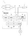
- FIG. 1 is a diagram illustrating an example of a left eye image and a right eye image included in a 3D image.
- FIG. 2 is a diagram illustrating a 3D image to which a reference area image and a corresponding area image are added.
- FIG. 3 is a diagram showing a schematic configuration of the information processing system according to the first and second embodiments.
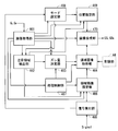
- FIG. 4 is a block diagram illustrating a functional configuration according to the image processing apparatus.
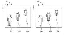
- FIG. 5 is a diagram illustrating an example of a left-eye image and a right-eye image included in a 3D image.
- FIG. 6 is a diagram illustrating a 3D image to which a reference area image and a corresponding area image are added.
- FIG. 1 is a diagram illustrating an example of a left eye image and a right eye image included in a 3D image.
- FIG. 2 is a diagram illustrating a 3D image to which a reference area image and a corresponding area image are added.
- FIG. 3
- FIG. 7 is a diagram illustrating a 3D image to which a reference area image and a corresponding area image are added.
- FIG. 8 is a diagram illustrating a 3D image to which a reference area image and a corresponding area image are added.
- FIG. 9 is a flowchart showing the operation of the image processing apparatus.
- FIG. 10 is a diagram illustrating an example of the left-eye image and the right-eye image included in the 3D image.
- FIG. 11 is a diagram illustrating a 3D image to which a reference area image and a corresponding area image are added.
- FIG. 12 is a diagram illustrating an aspect in which the reference area image and the corresponding area image are added.
- FIG. 13 is a diagram illustrating an aspect in which the reference area image and the corresponding area image are added.
- FIG. 14 is a diagram illustrating a 3D image to which a reference area image and a corresponding area image are added.
- a stereoscopically viewable image (also referred to as a 3D image) is displayed, for example, a left having a relationship in which the positions of pixels indicating the same portion of the display object are shifted in one direction.
- a left-eye image image for the eye
- G L image for the right eye and G R are prepared.
- the one direction is a direction that can match the direction in which the human left eye and the right eye are separated from each other, and is set, for example, in the horizontal direction of the image.
- Image G L and the right eye image G R for the left eye may be obtained by imaging using the stereo camera.
- the stereo camera has two cameras corresponding to a human left eye and a right eye.
- it is an image in which the image G L is the left-eye as a reference (also referred to as reference image) is an image (also referred to as the corresponding image) the right eye image G R corresponds to the reference image.
- Right eye image G R is the reference image
- the image G L may be the corresponding image for the left eye.
- the image G L for the left eye (also referred to as object area) area indicating the two objects comprise O1 L, O2 L, how the right-eye image G R comprises two object region O1 R, O2 R It is shown.
- the object areas O1 L and O1 R indicate the same person, and the object areas O2 L and O2 R indicate other same persons.
- the position of the object area O1 L, O2 L occupying an image G L for the left eye the position of the object area O1 R, O2 R occupy the right-eye image G R are deviated to the left.
- the right-eye image G R compared as is facilitated, and the broken line is attached to a position corresponding to the outer edge of the object region O1 L, O2 L occupying an image G L for the left eye .
- the amount of deviation between the position of the object area O1 occupy the position and the right-eye image G R of the object region O1 L occupying image G L for the left eye R (also referred to as parallax) of cases can be considered somewhat less.
- the deviation amount between the position of the position and the right-eye image G object area occupying R O2 R object region O2 L occupying image G L for the left eye (also referred to as parallax) of cases can be considered somewhat less.
- a region image (first image) for the left eye having a relationship in which the positions of pixels indicating the same portion of the display object are shifted in one direction by a first certain amount of displacement (also referred to as first displacement amount).
- I1 L also referred to as a reference area image
- an area image for the right eye also referred to as a first corresponding area image
- I1 R is acquired.
- a region image for the left eye also referred to as a second reference region image
- a second certain amount of displacement also referred to as a second amount of displacement
- an image (also referred to as a left-eye composite image) GS L in which the left-eye image GL , the first reference region image I1 L, and the second reference region image I2 L are combined is generated. Further, (also referred to as the right-eye synthesized image) right eye image G R and the first corresponding region image I1 R and the second image and the corresponding region image I2 R is synthesized GS R is generated.
- the left side of FIG. 2, (also referred to as the left-eye image area) image region corresponding to the image G L for the left eye first reference region image in the vicinity of the outer periphery of the TA L I1 L and the second reference region image I2 an example of a combined image GS L left eye L and are synthesized is shown.
- the left-eye synthesized image GS L for example, the first reference region image I1 L in accordance with the left position of the lower half in the vicinity of the outer periphery of the eye image area TA L (also referred to as a first reference-be-combined position) P1 L Has been placed.
- the position of the upper half in the vicinity of the outer circumference of the left-eye image area TA L (also referred to as a second reference object synthetic position) P2 L in accordance with a second reference region image I2 L is disposed.
- the arrangement of the first and second reference area images I1 L and I2 L in the vicinity of the outer periphery of the left-eye image GL makes it difficult for the user to prevent stereoscopic viewing of the 3D image.
- FIG. 2 On the right side of FIG. 2, (also referred to as the right-eye image area) image region corresponding to the right eye image G R TA periphery first corresponding region image in the vicinity of the R I1 R and the second corresponding region image I2 an example of R and is synthesized right eye combined image GS R is shown.
- a right-eye synthesized image GS R for example, the right-eye image area TA position of the lower half in the vicinity of the outer periphery of the R (also referred to as a first correspondence-be-combined position) P1 first corresponding region image in accordance with the R I1 R is Has been placed.
- the right upper half position in the vicinity of the outer periphery of the eye image area TA R (also referred to as a second correspondence the combination position) P2 in accordance with the R second corresponding region image I2 R is arranged.
- aspects and left-eye synthesized image GS L and the right-eye synthesized image GS R is displayed as an image synthesized or the left-eye synthesized image GS L and the right-eye synthesized image GS R
- Display of a 3D image can be realized by a mode in which images are sequentially displayed in a short time.
- both images G L and the right eye image G R for the left eye, included in each frame of video, for example, the left-eye synthesized image GS L is displayed as an image of the first field, synthesized for the right eye image GS R is interlaced displays may be employed as the image of the second field.
- first reference region image I1 L and the first corresponding region image I1 R and the second reference region image I2 L and the second corresponding region image I2 R is, an image G R image G L and the right eye left eye May be images of different fields or images of different frames.
- the combination of the first reference area image I1 L and the first corresponding area image I1 R gives the user a sense of depth corresponding to the first shift amount
- the second reference area image I2 L and the first reference area image I1 L combination of 2 corresponding region image I2 R gives an sense of depth corresponding to the second shift amount to the user.
- FIG. 3 is a diagram illustrating a schematic configuration of the information processing system 1 according to the first embodiment.
- the information processing system 1 includes a stereo camera 2, an information processing device 4, and a line-of-sight detection sensor 5.
- the information processing device 4 is connected to the stereo camera 2 and the line-of-sight detection sensor 5 so as to be able to transmit and receive data.
- the stereo camera 2 has a camera 21 and a camera 22.
- Each of the cameras 21 and 22 has a function of a digital camera having an image sensor such as a CCD.
- Each of the cameras 21 and 22 performs a photographing operation of receiving light from the subject and acquiring information indicating the distribution regarding the luminance of the subject as image data by photoelectric conversion.
- the optical axis of the camera 21 and the optical axis of the camera 22 are separated by a predetermined distance in the horizontal direction.
- the predetermined distance is also referred to as a base line length, and is set to a distance equivalent to the distance between the center of the average human left eye and the center of the right eye, for example.
- a stereo image is acquired by performing a photographing operation with the camera 21 and the camera 22 at substantially the same timing.
- the stereo image includes a set of an image for the left eye and an image for the right eye, and can be displayed so as to enable stereoscopic viewing by the user.
- Ns sets (Ns is an integer of 2 or more) of stereo images are obtained by performing a plurality of times of continuous shooting with the camera 21 and the camera 22 at a predetermined timing. May be acquired.
- the Ns sets of stereo images correspond to images of Ns frames included in a moving image that can be stereoscopically viewed.
- the line-of-sight detection sensor 5 detects a portion of the screen of the display unit 42 included in the information processing device 4 that is noticed by the user (also referred to as a portion of interest).
- the display unit 42 and the line-of-sight detection sensor 5 are fixed to each other with a predetermined arrangement relationship.
- a user's image is first obtained by shooting, and then the direction of the user's line of sight is detected by analyzing the image, and then the user on the screen of the display unit 42 The part of interest is detected.
- the analysis of the image can be realized, for example, by detecting the orientation of the face using pattern matching, and identifying the white-eye portion and the black-eye portion in both eyes using a color difference.
- information relating to one or more stereo images obtained by the stereo camera 2 can be transmitted to the information processing device 4 via the communication line 3a.
- information related to the target portion obtained by the line-of-sight detection sensor 5 can be transmitted to the information processing apparatus 4 via the communication line 3b.
- the communication lines 3a and 3b may be wired lines or wireless lines.
- the information processing apparatus 4 has a function of, for example, a personal computer (personal computer).
- the information processing apparatus 4 includes an operation unit 41, a display unit 42, an interface (I / F) unit 43, a storage unit 44, an input / output unit 45, and a control unit 46.
- the operation unit 41 includes, for example, a mouse and a keyboard.
- the display unit 42 includes, for example, a liquid crystal display.
- the I / F unit 43 receives information from the stereo camera 2 and the line-of-sight detection sensor 5.
- the storage unit 44 includes, for example, a hard disk and stores each image obtained by the stereo camera 2. Further, the storage unit 44 stores a program PG1 and the like for realizing various operations in the information processing apparatus 4.
- the input / output unit 45 includes, for example, a disk drive, can receive the storage medium 6 such as an optical disk, and can exchange data with the control unit 46.
- the control unit 46 includes a CPU 46 a that functions as a processor and a memory 46 b that can temporarily store information, and controls each unit of the information processing apparatus 4.
- various functions, various information processing, and the like are realized by reading and executing the program PG1 in the storage unit 44. Data temporarily generated in this information processing is appropriately stored in the memory 46b.
- the information processing device 4 functions as an image processing device that generates a 3D image, and also functions as an image display system that causes the display unit 42 to display the 3D image.
- the control unit 46 can store the program stored in the storage medium 6 in the storage unit 44 or the like via the input / output unit 45.
- FIG. 4 is a block diagram illustrating a functional configuration of the image processing apparatus realized by the control unit 46.
- the functional configuration of the image processing apparatus includes an image acquisition unit 461 as a first acquisition unit, a region of interest detection unit 462, a shift amount determination unit 463, a region image acquisition unit 464 as a second acquisition unit, and a signal reception unit. 465, an area image setting unit 466, a processing control unit 467, a mode setting unit 468, a position specifying unit 469, and an image composition unit 470 are included.
- Image acquisition unit 461 acquires information of the stereo images and an image G L and the right eye image G R for the left eye, i.e., the information of possible image stereoscopically (also referred to as a first stereoscopic image information).
- the image G L and the right eye image G R for the left eye the position of the pixel indicating the same portion of the object in one direction (here, horizontal direction) and has a relationship displaced in.
- a plurality of stereo images can be acquired in response to a plurality of times of shooting by the stereo camera 2.
- Attention area detection unit 462 according to a preset detection rule, the region of interest captured the same object to be predicted from a set of image G L and the right eye image G R for the left eye and that catching user's eye Detect a pair.
- the set of the region of interest, the set of the region of interest to be detected (also referred to as reference region of interest) attention area detected from the left-eye image G L from right eye image G R (also referred to as a corresponding region of interest) included.
- the n-th deviation amount includes a plurality of deviation amounts including the first deviation amount and the second deviation amount.
- shift amount determining unit 463 for example, between the image G L and the right eye image G R for the left eye, in response to the deviation amount of the position of the pixel indicating the same portion of the object (also referred to as parallax), first One or more deviation amounts among a plurality of deviation amounts including the deviation amount and the second deviation amount may be determined.
- the region image acquisition unit 464 acquires information (also referred to as n-th region image information) related to the n-th reference region image In L for the left eye and the n-th corresponding region image In R for the right eye.
- the position of the pixel indicating the same portion of the display object is determined in the one direction (here, the horizontal direction) by the shift amount determination unit 463.
- n deviation amount In the area image acquisition unit 464, for example, the first reference area image I1 L and the first corresponding area image I1 R having a relationship in which the positions of the pixels indicating the same portion of the display object are shifted by the first shift amount in one direction are included.
- Such first region image information can be acquired. Further, in the region image acquisition unit 464, the second reference region image I2 L and the second corresponding region image I2 R having a relationship in which the positions of the pixels indicating the same portion of the display object are shifted by the second shift amount in one direction are displayed. Such second region image information can be acquired.
- the signal receiving unit 465 receives a signal input to the control unit 46 according to the operation of the operation unit 41 by the user.
- Area image setting unit 466 sets the size of the n-th reference region image an In L and the n corresponding region image an In R, color, and one or more conditions of the shape.
- Processing control unit 467 the synthesis processing by the acquisition process and the image synthesis unit 470 by the region image acquiring unit 464 to execute on the basis of the image G L and the right eye image G R for the left eye.
- the acquisition process is a process in which the area image acquisition unit 464 acquires the nth area image information.
- the synthetic process a plurality of images including the image G L and the right eye image G R for the left eye and the n reference region image an In L and the n corresponding region image an In R are synthesized by the image synthesizing unit 470 It is processing.
- the mode setting unit 468 sets the position specifying unit 469 to any one of a plurality of modes including the first mode and the second mode.
- the mode setting unit 468 may set the mode of the position specifying unit 469 in accordance with the signal received by the signal receiving unit 465. For example, in accordance with a signal received by the signal receiving unit 465, the attention area detection unit 462 enters a mode in which the attention area is detected (also referred to as a detection permission mode) or a mode in which the attention area is not detected (also referred to as a detection inhibition mode). Can be set.
- the mode setting unit 468 based on the image G L for the left eye obtained by the image acquisition unit 461 and the right-eye image G R, to the mode of position designator 469 may be set, the region of interest The mode of the detection unit 462 may be set.
- the n-th reference region image an In L is (also referred to as n-th reference the synthetic position) by the position synthesized and Pn L, the position where the first n corresponding region image an In R are combined (the n corresponding object synthesizing Pn R is also designated.
- the n-th reference the synthetic position Pn L includes a first reference target combined position P1 L and the second reference-be-combined position P2 L is, in the first n corresponds the combined position Pn R, the first corresponding target A composite position P1 R and a second corresponding composite position P2 R may be included.
- a first mode of position designator 469 a mode for specifying the first n reference the combined position Pn L and the n corresponding object synthesizing position Pn R of the fixed, second mode position specifying unit 469, various when a mode for designating the n-th reference the combined position Pn L and the n corresponding the combined position Pn R is changed according to the conditions considered.
- Image combining unit 470 by synthesizing the image G L for the left eye, and the image G R for the right eye, and the n reference region image an In L, and a second n corresponding region image an In R, which can be stereoscopically Image information (also referred to as second stereoscopic image information) is generated.
- the n-th reference area image In L may be arranged according to the n-th reference composition position Pn L designated by the position designation unit 469, or arranged in accordance with a predetermined position determined in advance. Also good.
- the n-th corresponding region image In R may be arranged according to the n-th corresponding combined position Pn R specified by the position specifying unit 469 or may be arranged according to a predetermined position determined in advance. good.
- the n-th reference region image an In L for example, the first reference region image I1 L and the second reference region image I2 L is included
- the n-th corresponding region image an In R for example, the first corresponding region An image I1 R and a second corresponding region image I2 R may be included.
- Predetermined position may be arranged around the area of the image G L and the right eye image G R for the left eye, another image different from the image G L and the right eye image G R for the left eye It may be arranged in a region corresponding to the surrounding region.
- Another image may be, for example, another field image in an interlaced moving image or another frame image in a moving image.
- the second stereoscopic image information generated in this way can be visually output on the display unit 42 under the control of the control unit 46.
- the display unit 42 based on the second stereoscopic image information, and the image G L for the left eye, and the image G R for the right eye, the first reference region image I1 L, a first corresponding region image I1 R
- the second reference area image I2 L and the second corresponding area image I2 R can be superimposed and displayed at the same time.
- the left-eye image G L , the right-eye image G R , the first reference region image I1 L , the first corresponding region image I1 R , the second reference region image I2 L , and the second and one or more images of one or more images and a residual of the corresponding region image I2 R may be time sequentially displayed.
- the sense of distance and the image area TA L and the right-eye image area TA R for the left eye according to the object of giving the user a plurality of sets of the n reference region image an In L and the n corresponding region image an In R And a sense of distance related to the display object given to the user.
- the set of the n-th reference area image In L and the n-th corresponding area image In R includes a set of the first reference area image I1 L and the first corresponding area image I1 R (also referred to as a first set) and a first number. 2 reference area image I2 L and a set of the second corresponding region image I2 R (also referred to as a second pair) may be included.
- a plurality of sets of the n-th reference area image In L and the n-th corresponding area image In R including the first set and the second set can give the user a sense of distance to different display objects.
- the plurality of reference parallaxes give the user a plurality of depth sensations, and the depth sensation obtained by the user viewing the 3D image can be improved.
- Attention Area Detection Method As a detection method of the reference attention area and the corresponding attention area in the attention area detection unit 462, for example, one or more of the following first to sixth detection methods can be employed.
- Image region located near the center of the left-eye image G L and the right eye image G R is detected as the attention area.
- the contour of the object in the image G L for the left eye are extracted by image processing of the Hough transform or the like, the image area captured by the object located in the vicinity of the center of the left-eye image G L is detected as the reference region of interest obtain.
- the image area corresponding to the reference region of interest in the right-eye image G R can be detected as the corresponding region of interest.
- POC phase only correlation
- Left-eye image G L and the right eye image G R is the target, the image area indicating the specific type of object such as person or the like by the template matching or the like is detected as a region of interest.
- the reference region of interest can be detected by template matching or the like for the left eye image GL .
- the corresponding region of interest can be detected by template matching or the like intended for the right eye image G R. Then, for example, by using the POC method or the like, a set of the reference attention area and the corresponding attention area can be detected.
- a region of interest is detected by analyzing a motion vector for a plurality of stereo images. For example, a region indicating an object having a motion exceeding a certain threshold value can be detected as a reference attention region and a corresponding attention region by analyzing a motion vector for a plurality of stereo images. Specifically, by analyzing the motion vector for images G L for more left-eye is detected reference region of interest, the analysis of the motion vector for images G R for a plurality of right eye, corresponding interest Regions can be detected. Then, for example, by using the POC method or the like, a set of the reference attention area and the corresponding attention area can be detected.
- Left-eye image G L and the right eye image G R is the target, at least one of which is the detection area of the specific color and specific texture different from the surroundings is detected as the reference target region and corresponding region of interest
- the image G R image G L and the right eye left eye is targeted, the human characteristic detection region specific color such like skin color is detected as a color as a reference target region and corresponding region of interest Can be done.
- the image G R image G L and the right eye left eye is targeted, site contained in human head (eyes, hair, eyebrows, mouth, etc.) specific texture detection such color arrangement, etc.
- the selected region can be detected as the reference attention region and the corresponding attention region.
- a set of the reference attention area and the corresponding attention area can be detected.
- a case where a plurality of subjects of the same type (for example, humans) are partially overlapped in one image can be considered.
- information indicating the distance from the viewpoint which can be determined from the image G L and the right eye image G R for the left eye to the object is utilized, a plurality of objects can be distinguished.
- Information indicating the distance, the triangulation principle is utilized may be determined from the base line length of the parallax and the stereo camera 2 between the image G L and the right eye image G R for the left eye.
- the reference target region and corresponding region of interest is detected from the image G L and the right eye image G R for the left eye.
- the image G L and the right eye image G R for the left eye is targeted, one or more sets of image region indicating a specific type of object such as a person by the template matching or the like can be detected in advance. Then, an area corresponding to the target portion of the one or more sets of image areas can be detected as the reference target area and the corresponding target area.
- an image G R image G L and the right eye left eye Can be obtained by detecting a combination of a reference pixel and a corresponding pixel in which the same part of the object is captured.
- the combination or not of the same object reference region of interest which caught and corresponding region of interest can be determined by the parallax between the images G L and the right eye image G R for the left eye.
- the distance between the runner and the camera (viewpoint) will not change abruptly over time There is.
- the disparity between the images G L and the right eye image G R for the left eye within a predetermined range in a predetermined number of frames corresponding to a predetermined time
- There may be a region that changes only also referred to as a parallax slightly changing region.
- the reference region of interest and corresponding target person caught A region that is detected as a region and whose parallax is less than a predetermined value can be detected as a region where a distant view is captured.
- Deviation amount determination method As a determination method of the n-th shift amount in the shift amount determination unit 463, for example, one or more determination methods of the following first to third determination methods may be employed.
- a fixed value is determined as the n-th deviation amount based on information stored in advance in the storage unit 44 or the like.
- the first fixed value can be determined as the first shift amount
- the second fixed value can be determined as the second shift amount.
- the third fixed value may be determined as the third deviation amount. That is, N fixed values may be used to determine the first to N shift amounts in N stages. Thereby, by giving the user a sense of depth in which the N-stage parallax as a reference changes stepwise, the sense of depth that can be obtained by the user viewing the 3D image can be further improved.
- shift positions e.g. X, address Y
- a maximum value also referred to as a maximum shift amount
- a minimum value also referred to as a minimum shift amount
- the combination of the reference pixel and the corresponding pixel between the image G L and the right eye image G R for the left eye can be detected by searching for corresponding points using various methods POC method.
- the first shift amount is determined according to the maximum shift amount
- the second shift amount is determined according to the minimum shift amount. Note that the maximum deviation amount may be adopted as the first deviation amount, and the minimum deviation amount may be adopted as the second deviation amount.
- a shift amount different from the maximum shift amount according to a predetermined rule with the maximum shift amount as a reference may be determined as the first shift amount, or a minimum shift amount as a reference and a minimum shift amount according to the predetermined rule A different shift amount may be determined as the second shift amount.
- the predetermined rule for example, a value obtained by multiplying a maximum deviation amount by a first coefficient (for example, 0.8) is set as the first deviation amount, and a second coefficient (for example, 1.2 is obtained) as the minimum deviation amount. Or the like) may be adopted as a second deviation amount.
- the reference parallax is unlikely to be inappropriate for the original 3D image, and the sense of depth that can be obtained by the user viewing the 3D image can be improved.
- the first to N shift amounts in N stages may be determined.
- the first displacement amount is determined according to the maximum displacement amount
- the third displacement amount is determined according to the minimum displacement amount
- the intermediate displacement amount between the first displacement amount and the second displacement amount is the third displacement amount.
- the Nth shift amount is determined according to the minimum shift amount
- a value range between the first shift amount and the Nth shift amount is defined as N ⁇ 1.
- the shift amount to be divided can be determined as the second to (N-1) shift amounts, respectively.
- the Nth deviation amount is determined from the first deviation amount according to the distribution (that is, the parallax distribution).
- the N sets (N is an integer of 2 or more) of the reference attention areas and the corresponding attention areas those detected by the attention area detection unit 462 may be employed.
- a representative value is obtained for the amount of displacement (also referred to as parallax) of the pixel position indicating the same part of the object.
- this representative value for example, at least one of an average value, a maximum value, a minimum value, a mode value, and a median value can be adopted.
- the parallax at the center of gravity of the reference attention area or the corresponding attention area may be adopted as a representative value of the deviation amount.
- the parallax for each group of reference attention areas and corresponding attention areas where the same subject is captured changes with time.
- the representative value about the parallax which fluctuates about each reference attention area and corresponding attention area of which the same subject was caught may be calculated.
- this representative value for example, at least one of an average value, a maximum value, a minimum value, a mode value, and a median value can be adopted.
- the reference attention area and the corresponding attention area of each set in which the same object is captured can be detected, for example, by searching for corresponding points between the frame images by the POC method or the like.
- the first deviation amount is determined according to the maximum value (also referred to as the maximum representative deviation amount) of the representative values of the deviation amounts between the reference attention area and the corresponding attention area of each set, and the deviation amount
- the second deviation amount is determined according to the minimum value (also referred to as the minimum representative deviation amount) of the representative values.
- the maximum representative deviation amount may be adopted as the first deviation amount
- the minimum representative deviation amount may be adopted as the second deviation amount.
- the first shift amount can be determined based on a representative value (also referred to as a first focus shift amount) of a shift amount relating to a set (also referred to as a first set) of the reference focus region and the corresponding focus region.
- the second shift amount can be determined based on a representative value (also referred to as a second focus shift amount) of a shift amount relating to a set of other reference focus regions and a corresponding focus region (also referred to as a second set).
- the first noticeable deviation amount may be the first deviation amount
- the second noticeable deviation amount may be the second deviation amount.
- the reference parallax is unlikely to be out of focus with respect to the original 3D image, and the sense of depth that can be obtained by the user viewing the 3D image can be improved.
- a shift amount different from the maximum representative shift amount according to a predetermined rule with the maximum representative shift amount as a reference may be determined as the first shift amount, or the minimum representative shift amount according to a predetermined rule with the minimum representative shift amount as a reference A different shift amount may be determined as the second shift amount.
- a predetermined rule for example, a value calculated by multiplying the maximum representative deviation amount by a first coefficient (for example, 0.8) is set as the first deviation amount, and a second coefficient (for example, A rule may be employed in which a value calculated by multiplying 1.2 or the like) is set as the second shift amount.
- a shift different from the first target shift amount is based on a representative value (also referred to as a first target shift amount) of a shift amount relating to one set (also referred to as a first set) of the reference target region and the corresponding target region.
- the amount can be determined as the first deviation amount.
- a representative value also referred to as second attention shift amount
- the amount of deviation can be determined as the second amount of deviation.
- a value calculated by multiplying the first noticeable deviation amount by a first coefficient may be the first deviation amount
- the second noticeable deviation amount may be the second
- a value calculated by multiplying a coefficient for example, 1.2
- the difference between the first deviation amount and the maximum representative deviation amount and the difference between the second deviation amount and the minimum representative deviation amount may be specified by the user via the operation unit 41, for example.
- this difference may be determined based on a positional shift amount between the reference pixel and the corresponding pixel in an area other than the attention area including the background (also referred to as a non-attention area).
- the first to N shift amounts in N stages may be determined. If such a configuration is employed, the user can be given a sense of depth in which the N-stage parallax as a reference changes stepwise, and thus the sense of depth that can be obtained by the user can be further improved with respect to an object that can be noticed by the user.
- the first to N shift amounts may be determined based on the parallax. Specifically, the first to N shift amounts may be determined based on a parallax representative value between the reference non-attention area and the corresponding non-attention area. As this representative value, for example, at least one value of an average value, a maximum value, a minimum value, a mode value, and a median value of the deviation amounts can be adopted.
- two parallaxes that sandwich the representative value of the parallax from the front and the rear with the parallax representative value between the reference non-focused region and the corresponding non-focused region as the center can be determined as the first shift amount and the second shift amount.
- the first to N shift amounts in N stages may be determined around the representative value of parallax. At this time, the difference between adjacent shift amounts among the first to N shift amounts can be set to be substantially constant, for example.
- one of the first shift amount and the second shift amount may be determined by the first determination method, and the other may be determined by the second determination method or the third determination method.
- the region image setting unit 466 for example, one or more of the size, color, and shape of the n-th reference region image In L and the n-th corresponding region image In R according to the signal received by the signal receiving unit 465. Conditions can be set. Also, the area image setting unit 466, for example, according to one or more images of the image G L and the right eye image G R for the left eye, the n reference region image an In L and the n corresponding region image an In R One or more of the following sizes, colors, and shapes may be set.
- an In L and the n corresponding region image an In R
- the parameters defining the size of the n-th reference region image an In L and the n corresponding region image an In R for example, width and length, and the like.
- the colors of the n-th reference area image In L and the n-th corresponding area image In R include various colors such as red, green, and blue.
- the shapes of the n-th reference region image In L and the n-th corresponding region image In R include various shapes such as a frame shape and a rectangular shape.
- the n-th reference region image an In L and the n corresponding region
- the size of the image In R may be changed.
- the attention area detection unit 462 detects three sets of reference attention areas and corresponding attention areas.
- the first set of reference attention areas and corresponding attention areas are referred to as the first set of reference attention areas and corresponding attention areas
- the second set of reference attention areas and corresponding attention areas are referred to as the second set of reference attention areas and corresponding attention areas.
- the third set of reference attention areas and corresponding attention areas are referred to as attention areas
- the third set of reference attention areas and corresponding attention areas are referred to as attention areas.
- FIG. 5 includes left-eye image G L into three object region O1 L, O2 L, O3 L , includes right-eye image G R into three object region O1 R, O2 R, O3 R Is shown.
- the object areas O1 L and O1 R are areas indicating the first person
- the object areas O2 L and O2 R are areas indicating the second person
- the object areas O3 L and O3 R indicate the third person. It is an area.
- the position of the object area O1 occupies image G L for the left eye L, O2 L, O3 L
- shift position of the right eye image G object area O1 occupies R R, O2 R, O3 R is on the left ing.
- the right-eye image G R compared as is facilitated, with the broken lines in the position corresponding to the outer edge of the left-eye image G L occupies an object region O1 L, O2 L, O3 L Has been.
- the first set of reference attention areas is the object area O1 L
- the first set of corresponding attention areas is the object area O1 R
- the second set of reference attention areas is the object area O2 L
- the second Assume that the set of corresponding attention areas is the object area O2 R
- the third set of reference attention areas is the object area O3 L
- the third set of corresponding attention areas is the object area O3 R.
- the size of the nth reference area image In L can be changed so as to be equally divided (here, equally divided into three). Further, (here, the left side of one side) the particular side of the outer edge of the right-eye image area TA R to regions along the are (here 3 equal parts) equal in accordance with the number of the corresponding region of interest is In addition, the size of the n-th corresponding region image In R can be changed.
- Region Image Information Acquisition Method The acquisition of the n-th region image information related to the n-th reference region image In L and the n-th corresponding region image In R in the region image acquisition unit 464 is realized, for example, by sequentially performing the following first step and second step. Can be done.
- Second step> One image (for example, the nth reference region image In L ) based on the image pattern read in the first process is used as one of the images according to the nth shift amount determined by the shift amount determination unit 463.
- the other image (for example, the n-th corresponding region image In R ) is generated by shifting the position of each pixel in one direction.
- the n-th reference region image an In L and the n corresponding region image an In R is obtained.
- a set of image patterns corresponding to a plurality of deviation amounts is stored in advance in the storage unit 44 and the like, and a set of image patterns corresponding to the nth deviation amount determined by the deviation amount determination unit 463 is read from the storage unit 44 and the like.
- the n reference region image an in L and the n corresponding region image an in R may be acquired. That is, the n-th reference area image In L and the n-th corresponding area image In R need only have a relationship in which a display object such as a predetermined pattern is shifted by the n-th shift amount in one direction. Thereby, an image having a plurality of reference parallaxes can be easily acquired.
- a plurality of types of image patterns corresponding to a plurality of deviation amounts are stored in advance in the storage unit 44 and the nth deviation determined by the deviation amount determination unit 463 according to the conditions set by the area image setting unit 466.
- An image pattern corresponding to the amount may be employed. Thereby, the n-th reference area image In L and the n-th corresponding area image In R corresponding to the n-th deviation amount can be acquired.
- the processing control section 467 acquisition by the region image acquiring unit 464 It can be considered that the processing and the composition processing by the image composition unit 470 are not performed. Thereby, when a 3D image having almost no parallax is displayed, an image having a parallax as a reference is not given. For this reason, a decrease in the visibility of the image due to the addition of an unnecessary image can be suppressed.
- the position specifying unit 469 for example, the n reference be-combined position of a predetermined previously determined Pn L and the n corresponding object synthesizing position Pn R may be specified, first in accordance with the operation of the operation unit 41 by the user The n reference synthesized position Pn L and the nth corresponding synthesized position Pn R may be designated.
- the n-th reference the synthetic position Pn L, for example, including the surrounding area of the image G L for the left eye, and a region corresponding to the peripheral region in another image for the left eye image G L It can be specified in one or more of the plurality of regions.
- multiple first n corresponds the combined position Pn R include, for example, the surrounding area of the right-eye image G R, in another image and the right-eye image G R and an area corresponding to the peripheral region Can be specified in one or more of the regions.
- the first reference-be-combined position P1 L is specified in the lower half area of In the upper half area, the second reference combined position P2 L can be designated.
- the peripheral portion surrounding the right-eye image area TA R corresponding to the right eye image G R is specified first correspondence the combination positions P1 R in the region of the lower half, the in the region of the upper half 2 A corresponding combined position P2 R can be designated.
- the first reference synthesized position P1 L and the second reference synthesized position P2 L may be designated upside down, and the first corresponding synthesized position P1 R and the second corresponding synthesized position P2 R are specified. It may be specified upside down.
- the nth reference combined position Pn L may be designated.
- the specific side for example, as shown in the left figure of FIG. 6 and FIG. 7
- N in number (here, three) first according to a rectangular 1 to N reference synthesized positions P1 L to PN L (here, first to third reference synthesized positions P1 L to P3 L ) can be designated in order from the bottom.
- Corresponding synthesized positions P1 R to PN R (here, first to third corresponding synthesized positions P1 R to P3 R ) can be designated in order from the bottom.
- Corresponding synthesized positions P1 R to PN R (here, first to fourth corresponding synthesized positions P1 R to P4 R ) can be designated in order from the bottom.
- the n-th reference combined position Pn L and the n-th corresponding combined position Pn R may be positions of all pixels in a predetermined shape area such as a rectangle, or a predetermined shape area such as a rectangle can be specified. It may be a position (also referred to as a specific position).
- the specific position may be, for example, the position of one pixel such as an upper left pixel in a predetermined shape area, or may be a position of two or more pixels such as an upper left pixel and a lower right pixel in a predetermined shape area. There may be.
- the position specifying unit 469 according to one or more images of the image G L and the right eye image G R for the left eye, the n reference the combined position Pn L and the n corresponding object synthesizing position Pn R is designated obtain.
- the n reference the combined position Pn L is, and the surrounding area of the image G L for the left eye, in another image from the image G L for the left eye of the plurality including a region corresponding to the surrounding area It can be specified in one or more of the regions.
- n corresponding object synthesizing position Pn R is a plurality of regions including a region around the right-eye image G R, and a region corresponding to the surrounding area in another image and the right-eye image G R May be specified in one or more of the regions.
- the n reference the combined position Pn L is a region of the outer edge vicinity of the left-eye image G L, and a region corresponding to the region of the outer edge vicinity in another image for the left eye image G L It may be specified in one or more of a plurality of areas to be included.
- the n corresponding object synthesizing position Pn R is, and the outer edge portion near the region of the right eye image G R, and a region corresponding to the region in the vicinity outer edge in another picture and the right-eye image G R It may be specified in one or more of a plurality of areas to be included.
- first to fourth designation methods may be employed as the designation method for the nth reference synthesized position Pn L and the nth corresponding synthesized position Pn R.
- the disparity between the images G L and the right eye image G R for the left eye if and equal to or less than the second threshold value in the first threshold value or more, the n reference the combined position Pn L and the n corresponding object synthesizing An aspect in which the position Pn R is designated can be considered.
- the disparity between the images G L and the right eye image G R for the left eye if it exceeds or is less than the first threshold value, or the second threshold value, n-th reference the synthetic position Pn L And the n-th corresponding synthesized position Pn R is not designated.
- the difference between the maximum value and the minimum value of the parallax between the images G L and the right eye image G R for the left eye, as the smaller the smaller, Pn L and the n-th reference-be-combined position may be increased.
- N sets (N is an integer of 2 or more) according to the distribution of the parallax for the reference target region and corresponding region of interest the n reference-be-combined A position Pn L and an nth corresponding combined position Pn R are designated.
- the N sets (N is an integer of 2 or more) of the reference attention areas and the corresponding attention areas those detected by the attention area detection unit 462 may be employed.
- the nth reference composition position Pn L and the nth corresponding composition An aspect in which the position Pn R is designated can be considered. In this aspect, for example, if the difference between the maximum value and the minimum value of the parallax in the reference attention area and the corresponding attention area is less than the first threshold value or exceeds the second threshold value, the nth reference composite position Pn L And the n-th corresponding synthesized position Pn R is not designated.
- An aspect in which the synthesis position Pn R is designated can be considered.
- the attention area detection unit 462 detects two sets of reference attention areas and corresponding attention areas.
- the first set of reference attention areas and corresponding attention areas are referred to as the first set of reference attention areas and corresponding attention areas
- the second set of reference attention areas and corresponding attention areas are referred to as the second set of reference attention areas and corresponding attention areas. It shall be called a region of interest.
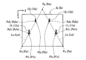
- the first reference combined position can be designated according to the position of the first set of reference attention areas occupying the left eye image GL . Further, according to the position of the first set of corresponding interest area occupying the right-eye image G R, the first correspondence to be combined position can be specified. Further, the second reference combined position can be designated according to the position of the second set of reference attention areas that occupy the left eye image GL . Furthermore, depending on the position of the second set of corresponding interest area occupying the right-eye image G R, the second corresponds the combined position can be specified.
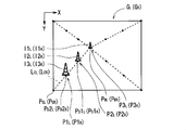
- the first set of reference attention areas is the object area O1 L
- the first set of corresponding attention areas is the object area O1 R
- the second set of reference attention areas is the object area O2 L. The case where the second set of corresponding attention areas is the object area O2 R is shown.
- the object region O1 L is a first predetermined direction (here, -X direction) is projected to A position P11 L indicating the area and a position P12 L indicating the area where the object area O1 L is projected in the second predetermined direction (here, the ⁇ Y direction) are designated as the first reference combined position P1 L. obtain.
- the object region O2 L (here, + X direction) the third predetermined direction and position P21 L indicating an area projected onto the object region O2 L is projected in a second predetermined direction
- the position P22 L indicating the selected area can be designated as the second reference combined position P2 L.
- the position P11 R indicating an area where the object region O1 R is projected in a first predetermined direction the object The position P12 R indicating the area where the area O1 R is projected in the second predetermined direction can be designated as the first corresponding combined position P1 R.
- region F of R, object region O2 R and the position P21 R indicating the region that is projected in a third predetermined direction, position indicating an area where the object region O2 R is projected to the second predetermined direction P22 R Can be designated as the second corresponding combined position P2 R.
- Kaware the number of sets of reference target region and corresponding region of interest also changes the number of sets of the n reference the combined position Pn L and the n corresponding the combined position Pn R.
- Kaware the position of the reference region of interest occupies the image G L for the left eye also change the n reference the synthetic position Pn L
- Kaware the position of the corresponding region of interest occupies the right-eye image G R the corresponding n-th The synthesized position Pn R also changes.
- Kaware the magnitude of the reference target region and corresponding region of interest the size of the area indicated by the n-th reference the combined position Pn L and the n corresponding object synthesizing position Pn R is also changed. Note that regardless of the size change of the reference target region and corresponding region of interest, be configured to the size of the area indicated by the n-th reference the combined position Pn L and the n corresponding object synthesizing position Pn R is not changed is employed good.
- the second designation method is combined with the third designation method, the nth reference combined position Pn for each set of the reference attention area and the corresponding attention area according to the parallax between the reference attention area and the corresponding attention area.
- the presence / absence of designation of L and the n-th corresponding synthesized position Pn R is switched.
- the nth reference region image In L is arranged in accordance with the nth reference composition position Pn L specified by the position specification unit 469, and the nth corresponding composition position specified by the position specification unit 469. is the n corresponding region image an in R are aligned with the pn R. Thereby, the second stereoscopic image information is generated.
- the image combining unit 470, the n-th reference region image an In L is, and the surrounding area of the image G L for the left eye, and a region corresponding to the peripheral region in another image for the left eye image G L May be arranged in one or more of a plurality of regions including.
- the n corresponding region image an In R is, and the surrounding region of the right eye image G R, in another image and the right-eye image G R of a plurality of regions including a region corresponding to the surrounding area It can be arranged in one or more of the regions.
- a left-eye composite image GS L in which the left-eye image GL and the n-th reference region image In L are combined is generated, right-eye image G R and the n corresponding region image an In R and is synthesized right eye combined image GS R may be generated.
- the second stereoscopic image information generated in this way only needs to include information in at least one of the first format and the second format.
- the first format is a mode in which the left-eye image G L , the right-eye image G R , the n-th reference area image In L, and the n-th corresponding area image In R are superimposed on one screen. Includes formats that can be displayed.
- the second format at least one of the left-eye image G L , the right-eye image G R , the n-th reference area image In L , and the n-th corresponding area image In R is displayed on one screen. It includes a format in which one or more images can be displayed in time sequence.
- FIG. 9 is a flowchart showing an operation flow of the image processing apparatus according to the first embodiment. This operation flow is realized by reading and executing the program PG1 in the storage unit 44 by the control unit 46. For example, execution of image processing relating to a 3D image in the information processing apparatus 4 is requested in accordance with an operation of the operation unit 41 by the user, and this operation flow is started.
- the first stereoscopic image information is acquired by the image acquisition unit 461.
- step S2 the mode setting unit 468 determines whether or not the attention area detection unit 462 is set to a mode for detecting the attention area. If the mode for detecting the attention area is set, the process proceeds to step S3. If the mode for detecting the attention area is not set, the process proceeds to step S4.
- step S3 the target area detection section 462, a target image G L and the right eye image G R for the left eye, the reference target region and corresponding region of interest is detected.
- step S4 the shift amount determination unit 463 determines the nth shift amount.
- the n-th deviation amount includes a plurality of deviation amounts including the first deviation amount and the second deviation amount.
- step S5 the area image setting unit 466, the size of the n-th reference region image an In L and the n corresponding region image an In R, color, and signal for setting one or more conditions of the shape (image setting signal Is also received by the signal receiving unit 465. If an image setting signal has been received, the process proceeds to step S6. If an image setting signal has not been received, the process proceeds to step S7.
- step S6 according to the image setting signal received by the signal receiving unit 465 by the region image setting unit 466, the size, color, and shape of the n-th reference region image In L and the n-th corresponding region image In R are selected. One or more conditions are set.
- step S7 the region image acquiring unit 464, the n-th region image information according to the n reference region image an In L and the n corresponding region image an In R is obtained.
- step S8 the mode setting unit 468, it is determined whether the signal for setting the mode according to the specification of the n-th reference the combined position Pn L and the n corresponding object synthesizing position Pn R is received by the signal receiving unit 465 The If a signal related to mode setting is accepted, the process proceeds to step S9. If a signal related to mode setting is not accepted, the process proceeds to step S10.
- step S9 the position specifying unit 469 selects one of a plurality of modes including the first mode and the second mode according to the signal received by the signal receiving unit 465 by the mode setting unit 468. Is set. Note that the position designation unit 469 is initially set to a predetermined mode before the mode is set in step S9.
- step S10 the position specifying unit 469, and the n reference the combined position Pn L and the n corresponding object synthesizing position Pn R is designated.
- step S11 the image combining unit 470, by which the image G L for the left eye, and the image G R for the right eye, and the n reference region image an In L, and a second n corresponding region image an In R are combined, Second stereoscopic image information is generated, and this operation flow ends.
- second stereoscopic image information corresponding to one still image may be generated based on one stereo image, or a moving image including a plurality of frame images based on a plurality of stereo images. Corresponding second stereoscopic image information may be generated.
- the n-th corresponding region image In R including I1 R and I2 R gives the user a plurality of depths.
- the left-eye image area TA L and the right eye image region TA R is easily increased sense of distance from the user to provide the user to the object. That is, the sense of depth that can be obtained by the user who is viewing the 3D image can be improved.
- the n shift amount including a first shift amount and the second shift amount is determined.
- the reference parallax is unlikely to be inappropriate for the 3D image.
- a reference region of interest in the image G L for the left eye in response to the parallax between the corresponding region of interest in the right-eye image G R, is determined as different parallaxes first and second shift amount is a parallax The Thereby, the feeling of depth which a user can obtain about the object which a user can pay attention to can be improved.
- the n reference to the position and size of the n-th reference the combined position Pn L and the n corresponding object synthesizing position Pn R is changed A synthesized position Pn L and an nth corresponding synthesized position Pn R are designated.
- an image having a plurality of reference parallaxes is provided at a position suitable for stereoscopic viewing of the 3D image. For this reason, the stereoscopic vision of the 3D image is hardly disturbed, and the sense of depth that can be obtained by the user viewing the 3D image can be improved.
- a reference region of interest in the image G L for the left eye, the n reference the combined position Pn L and the n corresponding object synthesizing position Pn R is specified in accordance with the number of sets of the corresponding region of interest in the right-eye image G R Is done.
- a reference region of interest in the image G L for the left eye, the position corresponding to the corresponding region of interest in the right-eye image G R, the n reference the combined position Pn L and the n corresponding object synthesizing position Pn R is designated Is done.
- the size of the n-th reference region image an In L and the n corresponding region image an In R, color, and one or more conditions of the shape is set. Thereby, it may be easier for the user to distinguish a plurality of objects in the 3D moving image.
- Second Embodiment> ⁇ (2-1) Outline of Processing According to Second Embodiment> 10 and 11 are diagrams for explaining the processing according to the second embodiment.
- the n reference region image an In L is, and the surrounding area of the image G L for the left eye, on the periphery of the region in the other image from the image G L for the left eye arranged in one or more regions of the plurality of areas including a corresponding region
- the n corresponding region image an in R is, and the surrounding region of the right eye image G R, different from the right-eye image G R
- the image is arranged in one or more of a plurality of regions including a region corresponding to the surrounding region of the image.
- the n reference region image an In L is superimposed on the inside of the area of the image G L for the left eye (also referred to as internal region)
- the n corresponding region image an in R may be disposed so as to overlap the interior region of the right eye image G R.
- the left eye image corresponding to the image G L for the left eye is arranged so as the n reference region image an in L is superimposed on the interior region of the area TA L, the n-th corresponding region image an in R the interior region of the right-eye image area TA R corresponding to the right eye image G R They can be arranged to overlap.
- the n-th reference region image an In L may be disposed in a region corresponding to the inner region of the left-eye image G L in another image from the image G L for the left eye
- the n corresponding region image an in R may be disposed in a region corresponding to the inner region of the right-eye image G R in another image and the right-eye image G R.
- the n-th reference region image An example of the left-eye composite image GS L in which In L is arranged is shown.
- the first reference area image I1 L is arranged in accordance with the first reference composition position P1 L
- the second reference area image I2 L is arranged in conformity with the second reference composition position P2 L
- the third A third reference area image I3 L is arranged in accordance with the reference composition position P3 L.
- the first corresponding region image I1 R is arranged according to the first corresponding combined position P1 R
- the second corresponding region image I2 R is arranged according to the second corresponding combined position P2 R
- the third A third corresponding region image I3 R is arranged in accordance with the corresponding combined position P3 R.
- the first to third reference area images I1 L to I3 L and the first to third corresponding area images I1 R to I3 R are placed on the side of the road at equal intervals along the road.
- An example of an image is shown.
- This pylon can be drawn by CG etc., for example.
- the process according to the second embodiment can be realized in the same information processing system 1 (FIG. 3) as that of the first embodiment. That is, the function as the image processing apparatus according to the second embodiment can be realized in the control unit 46. Moreover, the process which concerns on 2nd Embodiment may be implement
- the n-th reference area image In L and the n-th corresponding area image In R indicated by the n-th area image information may be a specific marker, for example.
- Specific markers for example, has a unique feature as long as it can easily be distinguished from the object to be originally contained in the image G L and the right eye image G R for the left eye for the user.
- the unique features can be realized by, for example, size, shape, color, texture, and the like.
- the left-eye image G L and the right eye image G R is an image capturing the object actually exists, as the specific markers, drawn by CG or the like, bar, various simple of such triangles, and arrows, etc.
- Various objects such as figures and vases, pylons, utility poles, etc. are conceivable.
- the user is less likely to confuse the object with a particular marker originally contained in the image G R image G L and the right eye left eye.
- markers, specific size, specific shape, while having a specific color, and unique texture, etc. as long as it is translucent image G L and the right eye image G R for the left eye Display of an image based on is difficult to be hindered.
- different types of region image information conditions may be set for each combination of the reference region of interest and the corresponding region of interest detected by the region of interest detection unit 462.
- conditions for different types of region image information include ones having different one or more of image size, color, and shape.
- N types of different region image information conditions may be set for N sets of reference attention regions and corresponding attention regions.
- markers including numbers 1, 2,..., N, etc. may be set in descending order of the parallax representative values of N sets of reference attention areas and corresponding attention areas. Thereby, it becomes easy for a user to distinguish an object.
- the M sets the image acquiring unit 461 (M is an integer greater than or equal to 2) moving image including the images G L and the right eye image G R for the left eye are obtained, the same object, common marker A configuration that continues to be attached may also be adopted.
- the target area detection section 462 from the first stereoscopic image information and an image G R image G L and the right eye left eye, according to a preset detection rule, an image G L for the left eye N sets of reference region of interest and the corresponding region of interest captured the same object to be expected to attract the user's eyes from the set of the right eye image G R is detected.
- the POC method is used to determine whether the reference regions of interest between frames capture the same object and whether the corresponding regions of interest between frames capture the same object. It can be detected by searching for the corresponding point.
- the color and the shape are common to the reference attention region and the corresponding attention region relating to the nth (n is an integer of 2 or more) object captured by each first stereoscopic image information.
- the n-th reference area image In L and the n-th corresponding area image In R can be acquired.
- the first reference region image I1 L having a common color and shape with respect to the reference attention region and the corresponding attention region relating to the first object captured by each first stereoscopic image information and A first corresponding region image I1 R can be acquired.
- the second reference area image I2 L and the second corresponding area image I2 R having the same color and shape with respect to the reference attention area and the corresponding attention area related to the second object captured by the first stereoscopic image information. Can be obtained. Thereby, it becomes easy for the user to distinguish a plurality of objects in the 3D moving image.
- the region image setting unit 466 causes the n-th reference region image In L and the n-th corresponding region for each combination of the reference attention region and the corresponding attention region according to the parallax between the reference attention region and the corresponding attention region.
- the size of the image In R may be set.
- an image having a plurality of reference parallaxes having a size suitable for stereoscopic viewing of a 3D image is provided.
- the stereoscopic view of the 3D image is hardly hindered, and the sense of depth that can be obtained by the user viewing the 3D image can be improved.
- the maximum value in one direction of the parallax between the images G L and the right eye image G R for the left eye may be set based on a deviation amount
- a minimum parallax value also referred to as a minimum deviation amount
- the size of the n-th reference region image an in L and the n corresponding region image an in R can be set.
- the size of the first reference area image I1 L and the first corresponding area image I1 R also referred to as the first size
- the size of the second reference area image I2 L and the second corresponding area image I2 R may be set.
- a division rule for example, a rule that divides the value range of the deviation amount according to the number of sets of the n-th reference region image In L and the n-th corresponding region image In R acquired by the region image acquisition unit 464, etc. Can be employed. This makes it easier for the user to feel a sense of depth in the 3D image due to a plurality of images having parallax that serves as a reference that changes stepwise.
- the method of specifying the n-th reference combined position Pn L and the n-th corresponding combined position Pn R in the position specifying unit 469 differs depending on the mode of the position specifying unit 469 set by the mode setting unit 468. For example, according to one or more images of the n-th reference the combined position Pn L and the n corresponding If the combined position Pn R is a region of fixed, and the left-eye image G L and the right eye image G R the n reference the combined position Pn L and the n corresponding object synthesizing position Pn R Te may sometimes such specified.
- the position specifying unit 469 for example, it may be previously given n-th reference that is determined to be combined position Pn L and the n corresponding object synthesizing position Pn R is specified but the in response to operation of the operation unit 41 by the user
- the n reference synthesized position Pn L and the nth corresponding synthesized position Pn R may be designated.
- the n-th reference the synthetic position Pn L for example, the internal area of the image G L for the left eye, among the plurality of regions including a region corresponding to the internal region of another image from the image G L for the left eye Are specified in one or more areas.
- the first n corresponds the combined position Pn R, for example, a plurality of areas including the internal area of the right-eye image G R, and a region corresponding to the internal region of another image and the right-eye image G R Are specified in one or more areas.
- the image combining unit 470, the n-th reference region image an In L is, the internal area of the image G L for the left eye, and a region corresponding to the internal region of another image from the image G L for the left eye Arranged in one or more of a plurality of regions.
- the n corresponding region image an In R is, the right-eye image G R and the internal area, separate from the right-eye image G R image among the plurality of regions including a region corresponding to the internal region of the Arranged in one or more regions.
- the position specifying unit 469 according to one or more images of the image G L and the right eye image G R for the left eye, the n reference the combined position Pn L and the n corresponding object synthesizing position Pn R is designated obtain.
- the n reference the combined position Pn L is, the internal area of the left eye image G L, the plurality of regions including a region corresponding to the internal region of another image from the image G L for the left eye One or more of these areas can be designated.
- n corresponding object synthesizing position Pn R is an internal region of the right eye image G R, among the plurality of regions including a region corresponding to the internal region of another image and the right-eye image G R Can be assigned to one or more regions.
- the first to fourth designation methods described above can be considered.
- the first to fourth designation methods described above can be considered.
- a specific example 1-3 on specifying the n reference the combined position Pn L and the n corresponding the combined position Pn R.
- n reference synthesized position Pn L and an nth corresponding synthesized position Pn R may be designated.
- the position specifying unit 469, the side of the road is identified by edge extraction and color analysis, etc., captured by the left-eye image G L and the right eye image G R by the search, etc. of the corresponding point of the POC method
- the distribution of the distance from the viewpoint for the recognized object can be recognized.
- a plurality of sets of the n-th reference combined position Pn L and the n-th corresponding combined position Pn R can be designated.
- the representative value of the parallax between the first reference area image I1 L and the first corresponding area image I1 R is the representative of the parallax between the reference attention area where the foreground person is captured and the corresponding attention area. It can be set to be equal to the value.
- the representative value for example, at least one of an average value, a maximum value, a minimum value, a mode value, and a median value can be adopted.
- FIG. 12 is a diagram for explaining one designation method of the n-th reference synthesized position Pn L and the n-th corresponding synthesized position Pn R for realizing another arrangement relating to a mark such as a pylon in the position designation unit 469. It is.
- a virtual reference point (also referred to as a first virtual reference point) PBL is provided, and the first virtual reference point PBL and four corners or the vicinity thereof are provided.
- Four virtual line segments (also referred to as virtual line segments) connecting the points are provided.
- a point (also referred to as a virtual reference dividing point) for virtually dividing one or more of the four virtual line segments according to a predetermined rule is provided.
- a first reference combined position P1 L is provided in a region including the first virtual reference point PBL and the vicinity thereof, and a second reference combined position P2 L is specified in the region including the virtual reference division point and the vicinity thereof.
- first correspondence-be-combined position P1 R is specified in a position corresponding to the first reference-be-combined position P1 L, first at a position corresponding to the second reference-be-combined position P2 L
- a 2-corresponding combined position P2 R is designated. That is, in the right-eye image G R, the second virtual reference point P BR and the first corresponding object synthesizing position P1 R in a region including the vicinity thereof is designated corresponding to the first virtual reference point P BL, virtual reference dividing The second corresponding combined position P2 R is designated in the region including the virtual corresponding division point corresponding to the point and the vicinity thereof.
- the plurality n-th reference the synthetic position Pn L comprising, for example, the internal area of the left eye image G L, and a region corresponding to the region of the internal in another image for the left eye image G L It may be specified in one or more of the areas.
- multiple first n corresponds the combined position Pn R include, for example, the internal region of the right eye image G R, and a region corresponding to the region of the internal in another image and the right-eye image G R It may be specified in one or more of the areas.
- the first and second virtual reference point P BL is P BR, for example, the position of an object located farthest from the user's perspective looking image G L and the right eye image G R for the left eye Can be set to a point corresponding to.
- the first and second virtual reference points P BL and P BR may be set according to a signal input by the operation of the operation unit 41 by the user, or the left eye image G L and the right eye image G R. May be obtained from the distribution of parallax.
- the predetermined rule for example, a rule that divides a virtual line segment into m equal parts (m is an integer of 2 or more) may be employed.
- the division number m may be set according to the number of sets of the reference region of interest and the corresponding region of interest in the image G L and the right eye image G R for the left eye, a virtual line segment from the user's perspective It may be set according to the amount of change in the distance to the object above. For example, a mode in which the division number m is small when the change amount is small and the division number m is large when the change amount is large can be considered. More specifically, an aspect in which the division number m increases by one every time the amount of change exceeds a multiple of a predetermined value can be considered.
- the first reference combined position P1 L is specified in a region including the first virtual reference point PBL and its vicinity.
- the first virtual reference dividing point P D 1 L and the second virtual reference dividing point to 3 divide one virtual line segment L CL connecting the first virtual reference point P BL and a point P CL of one corner P D 2 L is provided in order from the first virtual reference point P BL side.
- the second reference combined position P2 L is designated in the region including the first virtual reference dividing point P D 1 L and the vicinity thereof, and the third virtual reference dividing point P D 2 L and the region including the vicinity thereof are specified in the third region.
- a reference composition position P3 L is designated.
- first correspondence-be-combined position P1 R is designated in a region including a second virtual reference point P BR and its vicinity.
- the first virtual corresponding dividing points P D 1 R and the second imaginary corresponding dividing points divided into three parts one virtual line segment L CR connecting the second virtual reference point P BR and point P CR of one corner P D 2 R is provided in order from the second virtual reference point P BR side.
- the second corresponding combined position P2 R is specified in the region including the first virtual corresponding dividing point P D 1 R and the vicinity thereof, and the third corresponding in the region including the second virtual corresponding dividing point P D 2 R and the vicinity thereof.
- Corresponding synthesized position P3 R is designated.
- the first to third reference region images I1 L to I3 L are arranged according to the first to third reference synthesized positions P1 L to P3 L, and are matched to the first to third corresponding synthesized positions P1 R to P3 R.
- the first to third corresponding area images I1 R to I3 R can be arranged.
- the first set of the first reference area image I1 L and the first corresponding area image I1 R , the second set of the second reference area image I2 L and the second corresponding area image I2 R , and the third reference area If the parallax increases in the order of the third set of the image I3 L and the third corresponding region image I3 R , the sense of depth that can be obtained by the user viewing the 3D image can be further increased.
- FIG. 13 illustrates another designation method for the n-th reference synthesized position Pn L and the n-th corresponding synthesized position Pn R for realizing another arrangement related to the mark such as the pylon in the position designation unit 469.
- FIG. 13 illustrates another designation method for the n-th reference synthesized position Pn L and the n-th corresponding synthesized position Pn R for realizing another arrangement related to the mark such as the pylon in the position designation unit 469.
- first correspondence-be-combined position P1 R is provided at a position corresponding to the first reference-be-combined position P1 L, first at a position corresponding to the second reference-be-combined position P2 L Two corresponding synthesized positions P2 R are provided.
- the plurality n-th reference the synthetic position Pn L comprising, for example, the internal area of the left eye image G L, and a region corresponding to the region of the internal in another image for the left eye image G L It may be specified in one or more of the areas.
- multiple first n corresponds the combined position Pn R include, for example, the internal region of the right eye image G R, and a region corresponding to the region of the internal in another image and the right-eye image G R It may be specified in one or more of the areas.
- the first and second virtual reference point P BL is P BR, for example, the position of an object located farthest from the user's perspective looking image G L and the right eye image G R for the left eye Can be set to a point corresponding to.
- the first and second virtual reference points P BL and P BR may be points in the left eye image G L and the right eye image G R , or the left eye image G L and it may be a point of the image outside of the right-eye image G R.
- the first and second virtual reference points P BL and P BR may be set according to a signal input by the operation of the operation unit 41 by the user, or the left eye image GL and the right eye image. it may be determined from the distribution of parallax at G R.
- the predetermined rule for example, a rule that divides a virtual line segment into m equal parts (m is an integer of 2 or more) may be employed.
- the division number m may be set according to the number of sets of the reference region of interest and the corresponding region of interest in the image G L and the right eye image G R for the left eye, a virtual line segment from the user's perspective It may be set according to the amount of change in the distance to the object above. For example, a mode in which the division number m is small when the change amount is small and the division number m is large when the change amount is large can be considered. More specifically, an aspect in which the division number m increases by one every time the amount of change exceeds a multiple of a predetermined value can be considered.
- the first virtual reference point PBL is provided outside the left eye image GL .
- a reference division point P D 1 L and a second virtual reference division point P D 2 L are provided in this order from the point P CL side.
- the first reference combined position P1 L is specified in the vicinity of the first virtual reference dividing point P D 1 L
- the second reference combined position P2 L is specified in the vicinity of the second virtual reference dividing point P D 2 L.
- the second virtual reference point P BR is provided outside of the right-eye image G R.
- the first virtual reference line P BR and the first virtual line segment L CR connecting the two virtual line segments L CR connecting the two corner points P CR farthest from the second virtual reference point P BR are divided into three.
- Corresponding division points P D 1 R and second virtual corresponding division points P D 2 R are provided in order from the point PCR side. Then, the first corresponding combined position P1 R is specified in the vicinity of the first virtual corresponding dividing point P D 1 R , and the second corresponding combined position P2 R is specified in the vicinity of the second virtual corresponding dividing point P D 2 R. Has been.
- the first and second reference area images I1 L and I2 L are arranged according to the first and second reference synthesized positions P1 L and P2 L, and are matched with the first and second corresponding synthesized positions P1 R and P2 R.
- the first and second corresponding area images I1 R and I2 R can be arranged.
- the parallax is in the order of the first set of the first reference area image I1 L and the first corresponding area image I1 R and the second set of the second reference area image I2 L and the second corresponding area image I2 R. If the size is reduced, the sense of depth that can be obtained by the user viewing the 3D image can be further increased.
- nth reference synthesized position Pn L is designated in the vicinity of the reference attention area
- the nth corresponding synthesized position Pn R is designated in the vicinity of the corresponding attention area.
- the first reference target combined position is specified, the first set of corresponding interest area occupying the right-eye image G R Depending on the position, a first corresponding combined position may be designated.
- the second reference-be-combined position specified, the position of the second set of corresponding interest area occupying the right-eye image G R Depending on, a second corresponding combined position can be designated.
- a third reference object synthetic position is specified, the position of the third set of corresponding interest area occupying the right-eye image G R Depending on, a third corresponding synthesized position may be designated.
- FIG. 14 in the image area TA L for the left eye corresponding to the left-eye image G L, object area O1 L ⁇ O3 L first to third reference target synthesis position designated in the vicinity of the P1 L ⁇ P3
- An example of a left-eye synthesized image GS L of the first to third reference region image I1 L ⁇ I3 L are aligned with the L is shown.
- the object areas O1 L to O3 L correspond to the first to third reference attention areas.
- An example of the composite image GS R for the right eye in which the first to third corresponding area images I1 R to I3 R are arranged according to P3 R is shown.
- the object areas O1 R to O3 R correspond to first to third corresponding attention areas.
- a set of the first reference attention area and the first corresponding attention area (first set), a set of the second reference attention area and the second corresponding attention area (second set), and the third reference attention area
- the first reference combined position P1 L and the first corresponding combined position P1 R are designated for the combination with the largest representative value of the deviation amount among the set corresponding to the third corresponding attention area (third set).
- the second reference combined position P2 L and the second corresponding combined position P2 R are designated for the group having the next largest deviation amount among the first to third sets.
- the third reference combined position P3 L and the third corresponding combined position P3 R are designated for the set having the next largest deviation amount.
- the first reference synthesized position P1 L and the first corresponding synthesized position P1 R are designated immediately above the object area O1 L and the object area O1 R.
- a second reference synthesized position P2 L and a second corresponding synthesized position P2 R are designated immediately above the object area O2 L and the object area O2 R.
- a third reference synthesized position P3 L and a third corresponding synthesized position P3 R are designated immediately above the object area O3 L and the object area O3 R.
- a mark (for example, a mark including the number 1) indicating that the object area O1 L and the object area O1 R are areas in which the object that should be seen closest to the user's viewpoint is captured is an area image setting unit. 466 can be set for the first reference area image I1 L and the first corresponding area image I1 R. In addition, a mark (for example, a mark including the number 2) indicating that the object area O2 L and the object area O2 R are areas where the next object to be seen from the user's viewpoint is captured is an area image setting unit. by 466, it may be set for the second reference region image I2 L and the second corresponding region image I2 R.
- a mark (for example, a mark including the number 3) indicating that the object area O3 L and the object area O3 R are areas where the next object to be seen from the user's viewpoint is captured is an area image setting unit. 466 can be set for the third reference area image I3 L and the third corresponding area image I3 R. Thereby, it becomes easy to distinguish an object.
- the size of the n-th reference region image In L and the n-th corresponding region image In R is set to the size of the parallax between the object region On L and the object region On R by the region image setting unit 466. It can be set accordingly. Specifically, the larger the parallax, the larger the size of the n-th reference area image In L and the n-th corresponding area image In R given in the vicinity of the object area On L and the object area On R.
- the shift amount determination unit 463 may determine the n-th shift amount as an amount corresponding to the magnitude of the parallax between the object region On L and the object region On R. Specifically, the larger the parallax, the larger the n-th deviation amount can be. Thereby, the sense of depth that can be obtained by the user can be further improved with respect to an object that can be noticed by the user.
- the n-th reference area image In L and the n-th corresponding area image In R may be arranged in one or more adjacent areas above, below, left, and right of the object area On L and the object area On R.
- the n-th reference region image an In L and the n corresponding region image an In R may be a ring-like image surrounding the object area On L and the object region On R
- object area On L and the object region On R May be an image that is adjacent to and surrounds the object region On L and the object region On R.
- n reference region image in a region (region of non-interest) that the user has not noticed an In L and the n corresponding region image an In R is specified are contemplated.
- the non-attention area include a reference attention area detected by the attention area detection unit 462 and an area not included in the corresponding attention area.
- non-target region, out of the image G L and the right eye image G R for the left eye, the region in the vicinity of the end portion, a region showing a small object motion obtained from the analysis result of the motion vector, and color and texture Examples of such a region are inconspicuous. This makes it difficult for the display of the area that the user is paying attention to. As a result, it is possible to achieve both the suppression of visual discomfort and the improvement of the sense of depth that can be obtained by the user viewing the 3D image.
- an In L is, the internal area of the image G L for the left eye, an image G L for the left eye Are arranged in one or more areas among a plurality of areas including an area corresponding to the internal area.
- the plurality comprising two or more of the n corresponding region image an In R is an internal region of the right eye image G R, and a region corresponding to the internal region of another image from the right eye image G R Are arranged in one or more of the regions.
- the present invention is not limited to this.
- the more number of pairs of the reference region of interest and the corresponding region of interest, the n reference region image In L and the n corresponding region image In are combined with the image G L and the right eye image G R for the left eye
- the number of R may be reduced. This makes it difficult for the display of the area that the user is paying attention to. As a result, it is possible to achieve both the suppression of visual discomfort and the improvement of the sense of depth that can be obtained by the user viewing the 3D image.
- the reference region of interest in the number of sets is less than the predetermined number of the corresponding region of interest, the more number of pairs of the reference region of interest and the corresponding region of interest, image G L and the right eye image G R for the left eye
- the number of the n-th reference area image In L and the n-th corresponding area image In R to be combined may be increased.
- the number of sets of the reference attention area and the corresponding attention area exceeds a predetermined number, the larger the number of sets of the reference attention area and the corresponding attention area, the larger the left eye image G L and the right eye image G R.
- the number of the n-th reference area image In L and the n-th corresponding area image In R to be combined may be reduced.
Landscapes
- Engineering & Computer Science (AREA)
- Multimedia (AREA)
- Signal Processing (AREA)
- Testing, Inspecting, Measuring Of Stereoscopic Televisions And Televisions (AREA)
- Processing Or Creating Images (AREA)
Abstract
3D画像を見ているユーザーが得られる奥行き感を向上させる技術を提供することを図る。この目標を達成するために、物体の同一部分を示す画素の位置が一方向にずれている関係を有する基準画像と対応画像とに係る第1立体視画像情報が取得される。また、表示対象物の同一部分を示す画素の位置が一方向に第1ズレ量ずれている関係を有する第1基準領域画像と第1対応領域画像とに係る第1領域画像情報、および表示対象物の同一部分を示す画素の位置が一方向に第2ズレ量ずれている関係を有する第2基準領域画像と第2対応領域画像とに係る第2領域画像情報が取得される。更に、基準画像、対応画像、第1基準領域画像、第1対応領域画像、第2基準領域画像、および第2対応領域画像が合成されることで第2立体視画像情報が生成される。
Description
本発明は、画像処理技術に関する。
昨今、立体視が可能な動画(3D動画とも立体視動画とも言う)を利用したテレビ(3Dテレビとも言う)が脚光を浴びている。3Dテレビでは、同一物体を異なる視点から見た2つの画像が利用されて立体視が可能な画像(3D画像とも立体視画像とも言う)が生成される。
3D画像の技術では、左眼用の画像と右眼用の画像との間で物体の同一部分を示す画素の位置がずらされており、人間の眼の焦点調節機能が利用されて画像の奥行き感がユーザーに与えられる。なお、左眼用の画像と右眼用の画像との間における物体の同一部分を示す画素の位置のズレ量は「視差」とも称される。
この3D画像の技術は、種々の映像分野で採用されている。例えば、ステレオ画像から検出された視差が人間の眼の融合範囲に入るように調節されることで広い視野の範囲について画像の立体視が可能となる内視鏡装置が提案されている(例えば、特許文献1)。また、立体映像を表示し、その奥行き感を調整する場合に、基準となる参照用立体画像が表示される立体映像処理装置が提案されている(例えば、特許文献2)。
ところで、例えば、視差がある程度小さければ、画面の大きさ等によってはユーザーが奥行き感を得難い場合がある。つまり、ユーザーにとっては、同一物体であっても、実際に目視する場合と比較して、3D画像上で見る場合には、実際の物体とは異なる様に見えることがある。
このような3D画像の技術の現状に対して、画面に変化を付けたり、面白味を付加するため、あるいは立体視を容易とするために、3次元画像の周囲に枠画像が表示される技術が提案されている(例えば、特許文献3)。この技術では、複数の枠画像から使用する枠画像を選択することが可能である。
しかしながら、上記特許文献3の技術であっても、3D画像における奥行き感がユーザーには十分に得られない場合がある。
本発明は、上記課題に鑑みてなされたものであり、3D画像を見ているユーザーが得られる奥行き感を向上させる技術を提供することを目的とする。
上記課題を解決するために、第1の態様に係る画像処理装置は、物体の同一部分を示す画素の位置が一方向にずれている関係を有する基準画像と対応画像とに係る第1立体視画像情報を取得する第1取得部と、表示対象物の同一部分を示す画素の位置が前記一方向に第1ズレ量ずれている関係を有する第1基準領域画像と第1対応領域画像とに係る第1領域画像情報、および表示対象物の同一部分を示す画素の位置が前記一方向に第2ズレ量ずれている関係を有する第2基準領域画像と第2対応領域画像とに係る第2領域画像情報を取得する第2取得部と、前記基準画像、前記対応画像、前記第1基準領域画像、前記第1対応領域画像、前記第2基準領域画像、および前記第2対応領域画像を合成することで第2立体視画像情報を生成する合成部と、を備える。
第2の態様に係る画像処理装置は、第1の態様に係る画像処理装置であって、前記第2立体視画像情報が、一画面において前記基準画像と前記対応画像と前記第1基準領域画像と前記第1対応領域画像と前記第2基準領域画像と前記第2対応領域画像とを重畳している態様で同時期に表示可能とする第1形式の情報、および一画面において前記基準画像と前記対応画像と前記第1基準領域画像と前記第1対応領域画像と前記第2基準領域画像と前記第2対応領域画像とのうちの1以上の画像と残余の1以上の画像とを時間順次に表示可能とする第2形式の情報のうちの少なくとも一方の形式の情報を含む。
第3の態様に係る画像処理装置は、第1または第2の態様に係る画像処理装置であって、前記基準画像と前記対応画像との間における、物体の同一部分を示す画素の位置のズレ量に応じて、前記第1ズレ量および前記第2ズレ量のうちの少なくとも一方を決定する決定部、を更に備える。
第4の態様に係る画像処理装置は、第3の態様に係る画像処理装置であって、予め設定された検出ルールに従って、前記基準画像と前記対応画像との組からユーザーの目を惹くものと予測される同一の物体を捉えた基準注目領域と対応注目領域との組を検出する検出部、を更に備え、前記決定部が、前記検出部によって前記基準注目領域と前記対応注目領域との第1組および第2組が検出された場合に、前記第1組における物体の同一部分を示す画素の位置に係る第1注目ズレ量に基づいて、前記第1ズレ量を前記第1注目ズレ量とは異なるように決定し、前記第2組における物体の同一部分を示す画素の位置に係る第2注目ズレ量に基づいて、前記第2ズレ量を前記第2注目ズレ量とは異なるように決定する。
第5の態様に係る画像処理装置は、第1から第3の何れか1つの態様に係る画像処理装置であって、前記基準画像および前記対応画像のうちの1以上の画像に応じて、前記基準画像の内部領域、前記基準画像の周囲の領域、および前記基準画像とは別の画像に含まれる領域のうちの1以上の領域において、第1基準被合成位置と第2基準被合成位置とを指定し、前記対応画像の内部領域、前記対応画像の周囲の領域、および前記対応画像とは別の画像に含まれる領域のうちの1以上の領域において、第1対応被合成位置と第2対応被合成位置を指定する指定部、を更に備え、前記合成部が、前記第1基準被合成位置に合わせて前記第1基準領域画像を配置し、前記第1対応被合成位置に合わせて前記第1対応領域画像を配置し、前記第2基準被合成位置に合わせて前記第2基準領域画像を配置し、前記第2対応被合成位置に合わせて前記第2対応領域画像を配置する。
第6の態様に係る画像処理装置は、第5の態様に係る画像処理装置であって、予め設定された検出ルールに従って、前記基準画像と前記対応画像との組からユーザーの目を惹くものと予測される同一の物体を捉えた基準注目領域と対応注目領域との組を検出する検出部、を更に備え、前記検出部によって検出された前記基準注目領域と前記対応注目領域との組の数がN組(Nは2以上の自然数)である場合に、前記第2取得部が、表示対象物の同一部分を示す画素の位置が前記一方向に第Nズレ量ずれている関係を有する第N基準領域画像と第N対応領域画像とに係る第N領域画像情報を取得し、前記指定部が、前記基準画像の内部領域、前記基準画像の周囲の領域、および前記基準画像とは別の画像に含まれる領域のうちの1以上の領域において、第N基準被合成位置を指定し、前記対応画像の内部領域、前記対応画像の周囲の領域、および前記対応画像とは別の画像に含まれる領域のうちの1以上の領域において、第N対応被合成位置を指定し、前記合成部が、前記第N基準被合成位置に合わせて前記第N基準領域画像を配置し、前記第N対応被合成位置に合わせて前記第N対応領域画像を配置する。
第7の態様に係る画像処理装置は、第5の態様に係る画像処理装置であって、予め設定された検出ルールに従って、前記基準画像と前記対応画像との組からユーザーの目を惹くものと予測される同一の物体を捉えた基準注目領域と対応注目領域との組を検出する検出部、を更に備え、前記検出部によって、第1組の基準注目領域と対応注目領域、および第2組の基準注目領域と対応注目領域が検出される場合に、前記指定部が、前記基準画像を占める前記第1組の基準注目領域の位置に応じて前記第1基準被合成位置を指定し、前記対応画像を占める前記第1組の対応注目領域の位置に応じて前記第1対応被合成位置を指定し、前記基準画像を占める前記第2組の基準注目領域の位置に応じて前記第2基準被合成位置を指定し、前記対応画像を占める前記第2組の対応注目領域の位置に応じて前記第2対応被合成位置を指定する。
第8の態様に係る画像処理装置は、第7の態様に係る画像処理装置であって、前記第1基準領域画像および前記第1対応領域画像と、前記第2基準領域画像および前記第2対応領域画像との間で、画像のサイズ、色、および形状のうちの1以上が異なる。
第9の態様に係る画像処理装置は、第8の態様に係る画像処理装置であって、前記第1取得部が、複数の前記第1立体視画像情報を取得し、前記検出部が、前記検出ルールに従って、各前記第1立体視画像情報から、第1組の基準注目領域と対応注目領域、および第2組の基準注目領域と対応注目領域をそれぞれ検出し、前記第2取得部が、各前記第1立体視画像情報に対して、色および形状が共通する前記第1基準領域画像および前記第1対応領域画像に係る前記第1領域画像情報と、色および形状が共通する前記第2基準領域画像および前記第2対応領域画像に係る前記第2領域画像情報と、をそれぞれ取得する。
第10の態様に係る画像処理装置は、第1から第4の何れか1つの態様に係る画像処理装置であって、前記基準画像および該基準画像とは別の画像のうちの1以上の画像において、第1仮想基準点を含む領域に第1基準被合成位置を指定するとともに、前記第1仮想基準点と4隅または該4隅の近傍の点とを結ぶ4本の線分のうちの1本以上の線分を所定ルールで分割する点を含む領域に第2基準被合成位置を指定し、前記対応画像および該対応画像とは別の画像のうちの1以上の画像において、前記第1仮想基準点に対応する第2仮想基準点を含む領域に第1対応被合成位置を指定するとともに、前記第2仮想基準点と4隅または該4隅の近傍の点とを結ぶ4本の線分のうちの1本以上の線分を前記所定ルールで分割する点を含む領域に第2対応被合成位置を指定する指定部、を更に備え、前記合成部が、前記第1基準被合成位置に合わせて前記第1基準領域画像を配置し、前記第1対応被合成位置に合わせて前記第1対応領域画像を配置し、前記第2基準被合成位置に合わせて前記第2基準領域画像を配置し、前記第2対応被合成位置に合わせて前記第2対応領域画像を配置する。
第11の態様に係る画像処理装置は、第1から第4の何れか1つの態様に係る画像処理装置であって、前記基準画像および該基準画像とは別の画像のうちの1以上の画像において、該1以上の画像内または該1以上の画像外における第1仮想基準点と、4隅のうちの前記第1仮想基準点から最も遠い方から2隅または該2隅の近傍の点とを結ぶ2本の線分のうちの1本以上の線分を所定ルールで分割する第1基準分割点および第2基準分割点のうち、前記第1基準分割点を含む領域に第1基準被合成位置を指定するとともに、前記第2基準分割点を含む領域に第2基準被合成位置を指定する指定部、を更に備え、前記指定部が、前記対応画像および該対応画像とは別の画像のうちの1以上の画像において、該1以上の画像内または該1以上の画像外における前記第1仮想基準点に対応する第2仮想基準点と、4隅のうちの前記第2仮想基準点から最も遠い方から2隅または該2隅の近傍の点とを結ぶ2本の線分のうちの1本以上の線分を所定ルールで分割する第1対応分割点および第2対応分割点のうち、前記第1対応分割点を含む領域に第1対応被合成位置を指定するとともに、前記第2対応分割点を含む領域に第2対応被合成位置を指定し、前記合成部が、前記第1基準領域画像を前記第1基準被合成位置に合わせて配置し、前記第1対応領域画像を前記第1対応被合成位置に合わせて配置し、前記第2基準領域画像を前記第2基準被合成位置に合わせて配置し、前記第2対応領域画像を前記第2対応被合成位置に合わせて配置する。
第12の態様に係る画像処理装置は、第1から第11の何れか1つの態様に係る画像処理装置であって、ユーザーの入力に応じた信号を受け付ける受付部と、前記信号に応じて、前記第1基準領域画像、前記第1対応領域画像、前記第2基準領域画像、および前記第2対応領域画像のサイズ、色、および形状のうちの少なくとも1つを設定する設定部と、を更に備える。
第13の態様に係る画像処理装置は、第1から第11の何れか1つの態様に係る画像処理装置であって、前記基準画像および前記対応画像のうちの1以上の画像に応じて、前記第1基準領域画像、前記第1対応領域画像、前記第2基準領域画像、および前記第2対応領域画像のサイズ、色、および形状のうちの少なくとも1つを設定する設定部、を更に備える。
第14の態様に係る画像処理装置は、第13の態様に係る画像処理装置であって、前記第1取得部が、1以上の前記第1立体視画像情報を取得し、前記第2取得部が、表示対象物の同一部分を示す画素の位置が前記一方向に第3ズレ量ずれている関係を有する第3基準領域画像と第3対応領域画像とに係る第3領域画像情報を取得し、前記設定部が、各前記第1立体視画像情報に係る前記基準画像と前記対応画像との間における物体の同一部分を示す画素の位置の前記一方向へのズレ量のうち、最大ズレ量と、最小ズレ量と、前記最小ズレ量から前記最大ズレ量に至るズレ量の値域を分割ルールに従って分割する分割ズレ量との関係に応じて、前記第1基準領域画像および前記第1対応領域画像の第1サイズと、前記第2基準領域画像および前記第2対応領域画像の第2サイズと、前記第3基準領域画像および前記第3対応領域画像の第3サイズとの関係を設定する。
第15の態様に係る画像処理装置は、第14の態様に係る画像処理装置であって、前記分割ルールが、前記第2取得部で取得される、前記第1領域画像情報と前記第2領域画像情報とを含む複数の領域画像情報の数に応じて、前記ズレ量の値域を分割するルールである。
第16の態様に係る画像処理装置は、第1から第15の何れか1つの態様に係る画像処理装置であって、前記第2取得部による前記第1領域画像情報と前記第2領域画像情報とを含む複数の領域画像情報の取得処理、および前記合成部による前記基準画像と前記対応画像と前記第1基準領域画像と前記第1対応領域画像と前記第2基準領域画像と前記第2対応領域画像とを含む複数の画像の合成処理のうちの1以上の処理を、前記基準画像と前記対応画像とに基づいて実行させる制御部、を更に備える。
第17の態様に係る画像処理装置は、第1から第16の何れか1つの態様に係る画像処理装置であって、前記第1基準領域画像と前記第1対応領域画像とが、模様が前記一方向に前記第1ズレ量ずれている関係を有し、前記第2基準領域画像と前記第2対応領域画像とが、模様が前記一方向に前記第2ズレ量ずれている関係を有する。
第18の態様に係る画像処理方法は、(a)物体の同一部分を示す画素の位置が一方向にずれている関係を有する基準画像と対応画像とに係る第1立体視画像情報を取得する工程と、(b)表示対象物の同一部分を示す画素の位置が前記一方向に第1ズレ量ずれている関係を有する第1基準領域画像と第1対応領域画像とに係る第1領域画像情報、および表示対象物の同一部分を示す画素の位置が前記一方向に第2ズレ量ずれている関係を有する第2基準領域画像と第2対応領域画像とに係る第2領域画像情報を取得する工程と、(c)前記基準画像、前記対応画像、前記第1基準領域画像、前記第1対応領域画像、前記第2基準領域画像、および前記第2対応領域画像を合成することで第2立体視画像情報を生成する工程と、を備える。
第19の態様に係るプログラムは、情報処理装置に含まれる制御部において実行されることにより、前記情報処理装置を、第1から第17の何れか1つの態様に係る画像処理装置として機能させる。
第1から第17の何れの態様に係る画像処理装置によっても、3D画像を見ているユーザーが得られる奥行き感が向上し得る。
第2の態様に係る画像処理装置によれば、種々の表示態様が採用されても、3D画像を見ているユーザーが得られる奥行き感が向上し得る。
第3の態様に係る画像処理装置によれば、基準となる視差が3D画像に対して的外れなものとなり難いため、3D画像を見ているユーザーが得られる奥行き感が向上し得る。
第4の態様に係る画像処理装置によれば、ユーザーが注目し得る物体について、ユーザーが得られる奥行き感が向上し得る。
第5の態様に係る画像処理装置によれば、3D画像のうちの3D画像の立体視に適した位置に複数の基準となる視差を有する画像が付与されるため、3D画像の立体視が妨げられ難い。
第6の態様に係る画像処理装置によれば、物体の数に応じて基準となる視差を有する画像が3D画像に付与されて、ユーザーが注目し得る物体について奥行き感が向上し得る。
第7の態様に係る画像処理装置によれば、物体毎に基準となる視差を有する画像が3D画像に付与されるため、ユーザーが注目し得る物体について奥行き感が向上し得る。
第8および第9の何れの態様に係る画像処理装置によっても、物体が区別し易くなる。
第10および第11の何れの態様に係る画像処理装置によっても、3D画像を見ているユーザーが得られる奥行き感が更に高まり得る。
第12の態様に係る画像処理装置によれば、物体が更に区別し易くなる。
第13から第15の何れの態様に係る画像処理装置によっても、3D画像の立体視に適した大きさで複数の基準となる視差を有する画像が3D画像に付与されるため、3D画像の立体視が妨げられ難い。
第16の態様に係る画像処理装置によれば、3D画像の状態に応じて複数の基準となる視差を有する画像が3D画像に付与されるため、画像の視認性の低下が抑制され得る。
第17の態様に係る画像処理装置によれば、複数の基準となる視差を有する画像が容易に取得され得る。
第18の態様に係る画像処理方法および第19の態様に係るプログラムの何れによっても、3D画像を見ているユーザーが得られる奥行き感が向上し得る。
以下、本発明の実施形態を図面に基づいて説明する。図面では同様な構成および機能を有する部分に同じ符号が付され、重複説明が省略される。また、各図面は模式的に示されたものであり、例えば、各図面における画像上の表示物のサイズおよび位置関係等は正確に図示されたものではない。また、画像データと、画像データに基づいて表示される画像とをまとめて「画像」と適宜総称する。更に、各図面では、画像の左上の画素が原点とされ、該画像の長辺に沿った方向(ここでは、横方向)がX軸方向とされ、該画像の短辺に沿った方向(ここでは縦方向)がY軸方向とされる。そして、各画像の右方向が+X方向とされ、各画像の下方向が+Y方向とされる。なお、図1、図2、図5~図8、および図10~図14には、直交するXYの2軸が付されている。
<(1)第1実施形態>
<(1-1)第1実施形態に係る処理の概要>
図1および図2は、第1実施形態に係る処理を説明するための図である。
<(1-1)第1実施形態に係る処理の概要>
図1および図2は、第1実施形態に係る処理を説明するための図である。
図1で示されるように、立体視が可能な画像(3D画像とも言う)が表示されるために、例えば、表示対象物の同一部分を示す画素の位置が一方向にずれた関係を有する左眼用の画像(左眼用画像とも言う)GLと右眼用の画像(右眼用画像とも言う)GRとが準備される。
ここで、一方向は、人間の左眼と右眼とが離隔している方向に合致し得る方向であり、例えば、画像の横方向に設定される。左眼用画像GLと右眼用画像GRは、例えば、ステレオカメラを用いた撮影で取得され得る。ステレオカメラは人間の左眼と右眼とに相当する2つのカメラを有する。なお、本実施形態では、左眼用画像GLが基準となる画像(基準画像とも言う)とされ、右眼用画像GRが基準画像と対応する画像(対応画像とも言う)とされる。右眼用画像GRが基準画像とされ、左眼用画像GLが対応画像とされても良い。
図1では、左眼用画像GLが2つの物体を示す領域(物体領域とも言う)O1L,O2Lを含み、右眼用画像GRが2つの物体領域O1R,O2Rを含む様子が示されている。物体領域O1L,O1Rは同一人物を示し、物体領域O2L,O2Rは他の同一人物を示す。ここでは、左眼用画像GLを占める物体領域O1L,O2Lの位置に対して、右眼用画像GRを占める物体領域O1R,O2Rの位置が左にずれている。なお、図1では、右眼用画像GRにおいて、比較が容易となるように、左眼用画像GLを占める物体領域O1L,O2Lの外縁に対応する位置に破線が付されている。
ところで、例えば、左眼用画像GLを占める物体領域O1Lの位置と右眼用画像GRを占める物体領域O1Rの位置とのズレ量(視差とも言う)がある程度小さい場合が考えられる。また、左眼用画像GLを占める物体領域O2Lの位置と右眼用画像GRを占める物体領域O2Rの位置とのズレ量(視差とも言う)がある程度小さい場合が考えられる。この場合、3D画像が表示される画面の大きさを含む各種の表示条件等によっては、物体領域O1L,O1R,O2L,O2Rで示される物体に対してユーザーが奥行き感を得難くなり得る。換言すれば、同一物体であっても、実際に目視する場合と比較して、3D画像上で物体を見る場合には、実際の物体とは異なる奥行き感をユーザーに与え得る。
そこで、例えば、まず、表示対象物の同一部分を示す画素の位置が一方向に第1の或るズレ量(第1ズレ量とも言う)ずれた関係を有する左眼用の領域画像(第1基準領域画像とも言う)I1Lと右眼用の領域画像(第1対応領域画像とも言う)I1Rとが取得される。また、表示対象物の同一部分を示す画素の位置が一方向に第2の或るズレ量(第2ズレ量とも言う)ずれた関係を有する左眼用の領域画像(第2基準領域画像とも言う)I2Lと右眼用の領域画像(第2対応領域画像とも言う)I2Rとが取得される。
次に、左眼用画像GLと第1基準領域画像I1Lと第2基準領域画像I2Lとが合成された画像(左眼用合成画像とも言う)GSLが生成される。また、右眼用画像GRと第1対応領域画像I1Rと第2対応領域画像I2Rとが合成された画像(右眼用合成画像とも言う)GSRが生成される。
なお、図2の左側には、左眼用画像GLに相当する画像領域(左眼用画像領域とも言う)TALの外周の近傍に第1基準領域画像I1Lと第2基準領域画像I2Lとが合成された左眼用合成画像GSLの一例が示されている。左眼用合成画像GSLでは、例えば、左眼用画像領域TALの外周の近傍の下半分の位置(第1基準被合成位置とも言う)P1Lに合わせて第1基準領域画像I1Lが配置されている。更に、左眼用画像領域TALの外周の近傍の上半分の位置(第2基準被合成位置とも言う)P2Lに合わせて第2基準領域画像I2Lが配置されている。このような左眼用画像GLの外周近傍における第1および第2基準領域画像I1L,I2Lの配置により、ユーザーによる3D画像の立体視が妨げられ難い。
また、図2の右側には、右眼用画像GRに相当する画像領域(右眼用画像領域とも言う)TARの外周の近傍に第1対応領域画像I1Rと第2対応領域画像I2Rとが合成された右眼用合成画像GSRの一例が示されている。右眼用合成画像GSRでは、例えば、右眼用画像領域TARの外周の近傍の下半分の位置(第1対応被合成位置とも言う)P1Rに合わせて第1対応領域画像I1Rが配置されている。更に、右眼用画像領域TARの外周の近傍の上半分の位置(第2対応被合成位置とも言う)P2Rに合わせて第2対応領域画像I2Rが配置されている。このような右眼用画像GRの外周近傍における第1および第2対応領域画像I1R,I2Rの配置により、ユーザーによる3D画像の立体視が妨げられ難い。
そして、例えば、左眼用合成画像GSLと右眼用合成画像GSRとが合成された一画像として表示される態様、または左眼用合成画像GSLと右眼用合成画像GSRとが短時間で順次に表示される態様によって、3D画像の表示が実現され得る。なお、左眼用画像GLと右眼用画像GRの双方が、動画の各フレームに含まれ、例えば、左眼用合成画像GSLが第1フィールドの画像として表示され、右眼用合成画像GSRが第2フィールドの画像として表示されるインターレース方式が採用されても良い。また、第1基準領域画像I1Lと第1対応領域画像I1Rと第2基準領域画像I2Lと第2対応領域画像I2Rとが、左眼用画像GLと右眼用画像GRとは異なるフィールドの画像であっても良いし、異なるフレームの画像であっても良い。
以上のような表示により、第1基準領域画像I1Lと第1対応領域画像I1Rとの組合せが、第1ズレ量に応じた奥行き感をユーザーに与え、第2基準領域画像I2Lと第2対応領域画像I2Rとの組合せが、第2ズレ量に応じた奥行き感をユーザーに与える。この2つの異なる奥行き感との比較によって、左眼用画像領域TALと右眼用画像領域TARとがユーザーに与えるユーザーの視点から物体までの距離感が高まり易くなる。その結果、3D画像を見ているユーザーが得られる奥行き感が向上し得る。
<(1-2)情報処理システムの概略構成>
図3は、第1実施形態に係る情報処理システム1の概略構成を示す図である。
図3は、第1実施形態に係る情報処理システム1の概略構成を示す図である。
情報処理システム1は、ステレオカメラ2と情報処理装置4と視線検出センサ5とを備える。情報処理装置4は、ステレオカメラ2と視線検出センサ5とに対してデータの送受信が可能に接続されている。
ステレオカメラ2は、カメラ21とカメラ22とを有する。各カメラ21,22は、例えば、CCD等の撮像素子を有するデジタルカメラの機能を備える。各カメラ21,22では、被写体からの光を受光して、光電変換によって被写体の輝度に関する分布を示す情報を画像データとして取得する撮影動作が行われる。カメラ21の光軸とカメラ22の光軸は、例えば、水平方向に所定距離離隔されている。所定距離は、基線長とも称され、例えば、平均的な人間の左眼の中心と右眼の中心との離隔距離と等価な距離に設定される。
ステレオカメラ2では、略同一のタイミングでカメラ21とカメラ22とによって撮影動作が行われることで、ステレオ画像が取得される。ステレオ画像は、左眼用画像と右眼用画像との組を含み、ユーザーによって立体視が可能となる様に表示され得る。なお、左眼用画像および右眼用画像は、横方向にA個の画素(Aは自然数、例えば、A=1280)および縦方向にB個の画素(Bは自然数、例えば、B=960)を含むマトリックス状の画素の配列をそれぞれ有している。
また、ステレオカメラ2では、例えば、所定のタイミングでカメラ21とカメラ22とによって時間的に連続して複数回の撮影が行われることで、Ns組(Nsは2以上の整数)のステレオ画像が取得されても良い。このNs組のステレオ画像は、立体視が可能な動画に含まれるNs個のフレームの画像に相当する。
視線検出センサ5は、情報処理装置4に含まれる表示部42の画面上のうちのユーザーが注目している部分(注目部分とも言う)を検出する。表示部42と視線検出センサ5とは、所定の配置関係を有して相互に固定されている。視線検出センサ5では、例えば、まず、撮影でユーザーの画像が得られ、次に、その画像が解析されることでユーザーの視線の方向が検出され、そして、表示部42の画面上におけるユーザーによる注目部分が検出される。画像の解析は、例えば、パターンマッチングを用いた顔の向きの検出、および色の違いを用いた両眼における白眼の部分と黒眼の部分の識別等によって実現され得る。
なお、ステレオカメラ2で得られる1以上のステレオ画像に係る情報は、通信回線3aを介して情報処理装置4に送信され得る。また、視線検出センサ5で得られる注目部分に係る情報は、通信回線3bを介して情報処理装置4に送信され得る。通信回線3a,3bは、有線の回線であっても無線の回線であっても良い。
情報処理装置4は、例えばパーソナルコンピュータ(パソコン)の機能を有する。この情報処理装置4は、操作部41、表示部42、インターフェース(I/F)部43、記憶部44、入出力部45、および制御部46を備える。
操作部41は、例えば、マウスおよびキーボード等を含む。表示部42は、例えば、液晶ディスプレイ等を備える。I/F部43は、ステレオカメラ2および視線検出センサ5からの情報を受信する。記憶部44は、例えばハードディスク等を有し、ステレオカメラ2で得られる各画像等を記憶する。また、記憶部44には、情報処理装置4において各種動作を実現するためのプログラムPG1等が格納される。入出力部45は、例えば、ディスクドライブを備え、光ディスク等の記憶媒体6を受け付けて、制御部46との間でデータの授受を行い得る。
制御部46は、プロセッサーとして働くCPU46aと、情報を一時的に記憶し得るメモリ46bとを有し、情報処理装置4の各部を制御する。また、制御部46では、記憶部44内のプログラムPG1が読み込まれて実行されることで、各種機能および各種情報処理等が実現される。この情報処理において一時的に生成されるデータは、メモリ46bに適宜記憶される。そして、制御部46による制御によって、情報処理装置4は、3D画像を生成する画像処理装置として働き、更に、3D画像を表示部42に表示させる画像表示システムとしても働く。なお、制御部46は、記憶媒体6に記憶されているプログラムを、入出力部45を介して記憶部44等に格納させ得る。
<(1-3)画像処理装置の機能的な構成>
図4は、制御部46で実現される画像処理装置に係る機能的な構成を例示するブロック図である。画像処理装置に係る機能的な構成には、第1取得部としての画像取得部461、注目領域検出部462、ズレ量決定部463、第2取得部としての領域画像取得部464、信号受付部465、領域画像設定部466、処理制御部467、モード設定部468、位置指定部469、および画像合成部470が含まれる。
図4は、制御部46で実現される画像処理装置に係る機能的な構成を例示するブロック図である。画像処理装置に係る機能的な構成には、第1取得部としての画像取得部461、注目領域検出部462、ズレ量決定部463、第2取得部としての領域画像取得部464、信号受付部465、領域画像設定部466、処理制御部467、モード設定部468、位置指定部469、および画像合成部470が含まれる。
画像取得部461は、左眼用画像GLと右眼用画像GRとを含むステレオ画像の情報、すなわち立体視が可能な画像の情報(第1立体視画像情報とも言う)を取得する。左眼用画像GLと右眼用画像GRとは、物体の同一部分を示す画素の位置が一方向(ここでは、横方向)にずれた関係を有している。画像取得部461では、例えば、ステレオカメラ2による複数回の撮影に応じて、複数のステレオ画像が取得され得る。
注目領域検出部462は、予め設定された検出ルールに従って、左眼用画像GLと右眼用画像GRとの組からユーザーの目を惹くものと予測される同一物体を捉えた注目領域の組を検出する。注目領域の組には、左眼用画像GLから検出される注目領域(基準注目領域とも言う)と右眼用画像GRから検出される注目領域(対応注目領域とも言う)との組が含まれる。
ズレ量決定部463は、所定の決定ルールに従うことで、N個(Nは自然数である)のズレ量(第nズレ量とも言い、n=1~Nの自然数である)を決定する。第nズレ量には、第1ズレ量と第2ズレ量とを含む複数のズレ量が含まれる。ズレ量決定部463では、例えば、左眼用画像GLと右眼用画像GRとの間における、物体の同一部分を示す画素の位置のズレ量(視差とも言う)に応じて、第1ズレ量と第2ズレ量とを含む複数のズレ量のうちの1以上のズレ量が決定され得る。
領域画像取得部464は、左眼用の第n基準領域画像InLと右眼用の第n対応領域画像InRとに係る情報(第n領域画像情報とも言う)を取得する。第n基準領域画像InLと第n対応領域画像InRとは、表示対象物の同一部分を示す画素の位置が一方向(ここでは横方向)に、ズレ量決定部463で決定された第nズレ量ずれている関係を有する。領域画像取得部464では、例えば、表示対象物の同一部分を示す画素の位置が一方向に第1ズレ量ずれた関係を有する第1基準領域画像I1Lと第1対応領域画像I1Rとに係る第1領域画像情報が取得され得る。また、領域画像取得部464では、表示対象物の同一部分を示す画素の位置が一方向に第2ズレ量ずれた関係を有する第2基準領域画像I2Lと第2対応領域画像I2Rとに係る第2領域画像情報が取得され得る。
信号受付部465は、ユーザーによる操作部41の操作に応じて制御部46に入力される信号を受け付ける。
領域画像設定部466は、第n基準領域画像InLおよび第n対応領域画像InRのサイズ、色、および形状のうちの1以上の条件を設定する。
処理制御部467は、領域画像取得部464による取得処理および画像合成部470による合成処理を、左眼用画像GLおよび右眼用画像GRに基づいて実行させる。取得処理は、領域画像取得部464において第n領域画像情報が取得される処理である。また、合成処理は、画像合成部470において左眼用画像GLと右眼用画像GRと第n基準領域画像InLと第n対応領域画像InRとを含む複数の画像が合成される処理である。
モード設定部468は、第1モードと第2モードとを含む複数のモードのうちの何れか1つのモードに位置指定部469を設定する。モード設定部468は、信号受付部465で受け付けられた信号に応じて、位置指定部469のモードを設定しても良い。例えば、信号受付部465で受け付けられた信号に応じて、注目領域検出部462が、注目領域を検出するモード(検出許可モードとも言う)または注目領域を検出しないモード(検出禁止モードとも言う)に設定され得る。なお、モード設定部468では、画像取得部461で取得された左眼用画像GLと右眼用画像GRとに基づいて、位置指定部469のモードが設定されても良いし、注目領域検出部462のモードが設定されても良い。
位置指定部469は、第n基準領域画像InLが合成される位置(第n基準被合成位置とも言う)PnLと、第n対応領域画像InRが合成される位置(第n対応被合成位置とも言う)PnRと、を指定する。例えば、第n基準被合成位置PnLには、第1基準被合成位置P1Lと第2基準被合成位置P2Lとが含まれ、第n対応被合成位置PnRには、第1対応被合成位置P1Rと第2対応被合成位置P2Rとが含まれ得る。例えば、位置指定部469の第1モードが、固定の第n基準被合成位置PnLおよび第n対応被合成位置PnRを指定するモードであり、位置指定部469の第2モードが、種々の条件に応じて変更される第n基準被合成位置PnLおよび第n対応被合成位置PnRを指定するモードである場合が考えられる。
画像合成部470は、左眼用画像GLと、右眼用画像GRと、第n基準領域画像InLと、第n対応領域画像InRとを合成することで、立体視が可能な画像の情報(第2立体視画像情報とも言う)を生成する。ここで、第n基準領域画像InLは、位置指定部469によって指定された第n基準被合成位置PnLに合わせて配置されても良いし、予め決められた所定位置に合わせて配置されても良い。また、第n対応領域画像InRは、位置指定部469によって指定された第n対応被合成位置PnRに合わせて配置されても良いし、予め決められた所定位置に合わせて配置されても良い。なお、第n基準領域画像InLには、例えば、第1基準領域画像I1Lと第2基準領域画像I2Lとが含まれ、第n対応領域画像InRには、例えば、第1対応領域画像I1Rと第2対応領域画像I2Rとが含まれ得る。
所定位置は、例えば、左眼用画像GLおよび右眼用画像GRの周囲の領域において配置されても良いし、左眼用画像GLおよび右眼用画像GRとは異なる別の画像の該周囲の領域に対応する領域において配置されても良い。別の画像は、例えば、インターレース方式の動画における別のフィールド画像であっても良いし、動画における別のフレーム画像であっても良い。
このようにして生成された第2立体視画像情報は、制御部46の制御により、表示部42において可視的に出力され得る。例えば、表示部42では、第2立体視画像情報に基づいて、左眼用画像GLと、右眼用画像GRと、第1基準領域画像I1Lと、第1対応領域画像I1Rと、第2基準領域画像I2Lと、第2対応領域画像I2Rとが重畳されて同時期に表示され得る。また、例えば、表示部42では、左眼用画像GL、右眼用画像GR、第1基準領域画像I1L、第1対応領域画像I1R、第2基準領域画像I2L、および第2対応領域画像I2Rのうちの1以上の画像と残余の1以上の画像とが時間順次に表示されても良い。
この表示の際、左眼用画像領域TALと右眼用画像領域TARとがユーザーに与える物体に係る距離感が、複数組の第n基準領域画像InLと第n対応領域画像InRとがユーザーに与える表示物に係る距離感との比較によって、高められ得る。
そして、第n基準領域画像InLと第n対応領域画像InRとの組には、第1基準領域画像I1Lと第1対応領域画像I1Rとの組(第1組とも言う)および第2基準領域画像I2Lと第2対応領域画像I2Rとの組(第2組とも言う)が含まれ得る。この第1組と第2組とを含む複数組の第n基準領域画像InLと第n対応領域画像InRとが、ユーザーに異なる表示物までの距離感を与え得る。これにより、基準となる複数の視差が複数の奥行き感をユーザーに与えることで、3D画像を見ているユーザーが得られる奥行き感が向上し得る。
<(1-3-1)注目領域の検出方法>
注目領域検出部462における基準注目領域および対応注目領域の検出方法としては、例えば、下記の第1~6検出方法のうちの1以上の検出方法が採用され得る。
注目領域検出部462における基準注目領域および対応注目領域の検出方法としては、例えば、下記の第1~6検出方法のうちの1以上の検出方法が採用され得る。
<(1-3-1-1)第1検出方法>
左眼用画像GLおよび右眼用画像GRの中央部近傍に位置する画像領域が注目領域として検出される。例えば、ハフ変換等の画像処理により左眼用画像GLにおいて物体の輪郭が抽出され、左眼用画像GLの中央部近傍に位置する物体が捉えられた画像領域が基準注目領域として検出され得る。そして、右眼用画像GRにおいて基準注目領域に対応する画像領域が対応注目領域として検出され得る。ここでは、位相限定相関(POC)法等が用いられることで、例えば、基準注目領域に対応する対応注目領域が検出され得る。
左眼用画像GLおよび右眼用画像GRの中央部近傍に位置する画像領域が注目領域として検出される。例えば、ハフ変換等の画像処理により左眼用画像GLにおいて物体の輪郭が抽出され、左眼用画像GLの中央部近傍に位置する物体が捉えられた画像領域が基準注目領域として検出され得る。そして、右眼用画像GRにおいて基準注目領域に対応する画像領域が対応注目領域として検出され得る。ここでは、位相限定相関(POC)法等が用いられることで、例えば、基準注目領域に対応する対応注目領域が検出され得る。
<(1-3-1-2)第2検出方法>
左眼用画像GLおよび右眼用画像GRが対象とされ、テンプレートマッチング等によって人物等といった特定種類の物体を示す画像領域が注目領域として検出される。例えば、左眼用画像GLを対象としたテンプレートマッチング等によって基準注目領域が検出され得る。また、右眼用画像GRを対象としたテンプレートマッチング等によって対応注目領域が検出され得る。そして、例えば、POC法等が用いられることで、基準注目領域と対応注目領域との組が検出され得る。
左眼用画像GLおよび右眼用画像GRが対象とされ、テンプレートマッチング等によって人物等といった特定種類の物体を示す画像領域が注目領域として検出される。例えば、左眼用画像GLを対象としたテンプレートマッチング等によって基準注目領域が検出され得る。また、右眼用画像GRを対象としたテンプレートマッチング等によって対応注目領域が検出され得る。そして、例えば、POC法等が用いられることで、基準注目領域と対応注目領域との組が検出され得る。
<(1-3-1-3)第3検出方法>
画像取得部461によって複数のステレオ画像を含む動画を示す情報が取得されれば、複数のステレオ画像が対象とされた動きベクトルの解析によって、注目領域が検出される。例えば、複数のステレオ画像が対象とされた動きベクトルの解析によって、ある閾値を超える動きを有する物体を示す領域が基準注目領域および対応注目領域として検出され得る。具体的には、複数の左眼用画像GLを対象とした動きベクトルの解析によって、基準注目領域が検出され、複数の右眼用画像GRを対象とした動きベクトルの解析によって、対応注目領域が検出され得る。そして、例えば、POC法等が用いられることで、基準注目領域と対応注目領域との組が検出され得る。
画像取得部461によって複数のステレオ画像を含む動画を示す情報が取得されれば、複数のステレオ画像が対象とされた動きベクトルの解析によって、注目領域が検出される。例えば、複数のステレオ画像が対象とされた動きベクトルの解析によって、ある閾値を超える動きを有する物体を示す領域が基準注目領域および対応注目領域として検出され得る。具体的には、複数の左眼用画像GLを対象とした動きベクトルの解析によって、基準注目領域が検出され、複数の右眼用画像GRを対象とした動きベクトルの解析によって、対応注目領域が検出され得る。そして、例えば、POC法等が用いられることで、基準注目領域と対応注目領域との組が検出され得る。
<(1-3-1-4)第4検出方法>
左眼用画像GLおよび右眼用画像GRが対象とされ、周囲とは異なる特定色および特定のテクスチャーのうちの少なくとも一方が検知された領域が、基準注目領域および対応注目領域として検出される。例えば、左眼用画像GLと右眼用画像GRとが対象とされて、人間の特徴的な色である肌色等といった特定色が検知された領域が基準注目領域および対応注目領域として検出され得る。また、左眼用画像GLと右眼用画像GRとが対象とされて、人間の頭部に含まれる部位(目、頭髪、眉毛、口等)の色配列等といった特定のテクスチャーが検知された領域が基準注目領域および対応注目領域として検出され得る。そして、例えば、POC法等が用いられることで、基準注目領域と対応注目領域との組が検出され得る。
左眼用画像GLおよび右眼用画像GRが対象とされ、周囲とは異なる特定色および特定のテクスチャーのうちの少なくとも一方が検知された領域が、基準注目領域および対応注目領域として検出される。例えば、左眼用画像GLと右眼用画像GRとが対象とされて、人間の特徴的な色である肌色等といった特定色が検知された領域が基準注目領域および対応注目領域として検出され得る。また、左眼用画像GLと右眼用画像GRとが対象とされて、人間の頭部に含まれる部位(目、頭髪、眉毛、口等)の色配列等といった特定のテクスチャーが検知された領域が基準注目領域および対応注目領域として検出され得る。そして、例えば、POC法等が用いられることで、基準注目領域と対応注目領域との組が検出され得る。
なお、1つの画像において同じ種類の複数の被写体(例えば、人間)が部分的に重なり合っている状態が捉えられている場合が考えられる。この場合、例えば、左眼用画像GLと右眼用画像GRから求められ得る視点から被写体までの距離を示す情報が利用されて、複数の被写体が区別され得る。距離を示す情報は、三角測量の原理が利用されて、左眼用画像GLと右眼用画像GRとの間における視差およびステレオカメラ2の基線長から求められ得る。
<(1-3-1-5)第5検出方法>
視線検出センサ5で得られる注目部分に係る情報に基づいて、左眼用画像GLおよび右眼用画像GRから基準注目領域および対応注目領域が検出される。例えば、左眼用画像GLおよび右眼用画像GRが対象とされて、テンプレートマッチング等によって人物等の特定種類の物体を示す1組以上の画像領域が予め検出され得る。そして、この1組以上の画像領域のうちの注目部分に対応する領域が、基準注目領域および対応注目領域として検出され得る。
視線検出センサ5で得られる注目部分に係る情報に基づいて、左眼用画像GLおよび右眼用画像GRから基準注目領域および対応注目領域が検出される。例えば、左眼用画像GLおよび右眼用画像GRが対象とされて、テンプレートマッチング等によって人物等の特定種類の物体を示す1組以上の画像領域が予め検出され得る。そして、この1組以上の画像領域のうちの注目部分に対応する領域が、基準注目領域および対応注目領域として検出され得る。
<(1-3-1-6)第6検出方法>
左眼用画像GLおよび右眼用画像GRが対象とされ、ハフ変換等の画像処理によって各物体の輪郭の抽出が行われる。そして、輪郭で囲まれた各物体に係る領域のうち、左眼用画像GLと右眼用画像GRとの間における視差が、時間の経過に拘わらず、急激に変化しない領域が、人物が捉えられた基準注目領域および対応注目領域として検出される。なお、左眼用画像GLと右眼用画像GRとの間における視差は、例えば、POC法等を用いた対応点の探索によって、左眼用画像GLと右眼用画像GRとの間において物体の同一部分が捉えられた基準画素と対応画素との組合せが検出されることで求められ得る。また、同一の物体を捉えた基準注目領域と対応注目領域との組合せか否かについては、左眼用画像GLと右眼用画像GRとの間における視差によって判断され得る。
左眼用画像GLおよび右眼用画像GRが対象とされ、ハフ変換等の画像処理によって各物体の輪郭の抽出が行われる。そして、輪郭で囲まれた各物体に係る領域のうち、左眼用画像GLと右眼用画像GRとの間における視差が、時間の経過に拘わらず、急激に変化しない領域が、人物が捉えられた基準注目領域および対応注目領域として検出される。なお、左眼用画像GLと右眼用画像GRとの間における視差は、例えば、POC法等を用いた対応点の探索によって、左眼用画像GLと右眼用画像GRとの間において物体の同一部分が捉えられた基準画素と対応画素との組合せが検出されることで求められ得る。また、同一の物体を捉えた基準注目領域と対応注目領域との組合せか否かについては、左眼用画像GLと右眼用画像GRとの間における視差によって判断され得る。
例えば、マラソンの走者がカメラによって前方または後方から動画撮影される際、カメラが走者に追従していれば、走者とカメラ(視点)との距離が時間の経過に拘わらず急激には変化しない場合がある。この場合、輪郭で囲まれた各被写体に係る領域のうち、左眼用画像GLと右眼用画像GRとの間における視差が、所定時間に対応する所定数のフレームにおいて所定範囲内でしか変化しない領域(視差微変領域とも言う)が存在し得る。そこで、例えば、各視差微変領域のうち、左眼用画像GLと右眼用画像GRとの間における視差が所定値以上である領域が、人物が捉えられた基準注目領域および対応注目領域として検出され、視差が所定値未満である領域が、遠景が捉えられた領域として検出され得る。
<(1-3-2)ズレ量の決定方法>
ズレ量決定部463における第nズレ量の決定方法としては、例えば、次の第1~3決定方法のうちの1以上の決定方法が採用され得る。
ズレ量決定部463における第nズレ量の決定方法としては、例えば、次の第1~3決定方法のうちの1以上の決定方法が採用され得る。
<(1-3-2-1)第1決定方法>
予め記憶部44等に記憶された情報に基づいて、固定値が第nズレ量として決定される。例えば、第1固定値が第1ズレ量として決定され、第2固定値が第2ズレ量として決定され得る。これにより、基準となる複数の視差が複数の奥行き感をユーザーに与えることで、3D画像を見ているユーザーが得られる奥行き感が向上し得る。
予め記憶部44等に記憶された情報に基づいて、固定値が第nズレ量として決定される。例えば、第1固定値が第1ズレ量として決定され、第2固定値が第2ズレ量として決定され得る。これにより、基準となる複数の視差が複数の奥行き感をユーザーに与えることで、3D画像を見ているユーザーが得られる奥行き感が向上し得る。
更に、第3固定値が第3ズレ量として決定されても良い。すなわち、N個の固定値が用いられて、N段階の第1~Nズレ量が決定されても良い。これにより、基準となるN段階の視差が段階的に変化する奥行き感をユーザーに与えることで、3D画像を見ているユーザーが得られる奥行き感がより向上し得る。
<(1-3-2-2)第2決定方法>
左眼用画像GLと右眼用画像GRとの間における、物体の同一部分を示す画素の位置のズレ量に係る分布(すなわち視差の分布)に応じて、第nズレ量が決定される。
左眼用画像GLと右眼用画像GRとの間における、物体の同一部分を示す画素の位置のズレ量に係る分布(すなわち視差の分布)に応じて、第nズレ量が決定される。
例えば、まず、左眼用画像GLと右眼用画像GRとの間における物体の同一部分を示す基準画素と対応画素との全ての組合せについて、位置(例えばX,Yのアドレス)のズレ量の最大値(最大ズレ量とも言う)と最小値(最小ズレ量とも言う)とが算出される。なお、左眼用画像GLと右眼用画像GRとの間における基準画素と対応画素との組合せは、例えば、POC法等の種々の方法を用いた対応点の探索によって検出され得る。
次に、最大ズレ量に応じて第1ズレ量が決定され、最小ズレ量に応じて第2ズレ量が決定される。なお、最大ズレ量が第1ズレ量として採用されても良いし、最小ズレ量が第2ズレ量として採用されても良い。
また、最大ズレ量が基準とされて所定ルールに従って最大ズレ量とは異なるズレ量が第1ズレ量として決定されても良いし、最小ズレ量が基準とされて所定ルールに従って最小ズレ量とは異なるズレ量が第2ズレ量として決定されても良い。所定ルールとしては、例えば、最大ズレ量に第1係数(例えば、0.8等)が乗ぜられて得られる値が第1ズレ量とされ、最小ズレ量に第2係数(例えば、1.2等)が乗ぜられて得られる値が第2ズレ量とされるようなルールが採用され得る。
この第2決定方法が採用されれば、基準となる視差が元の3D画像に対して的外れなものとなり難いため、3D画像を見ているユーザーが得られる奥行き感が向上し得る。
なお、第2決定方法においても、N段階の第1~Nズレ量が決定されても良い。例えば、最大ズレ量に応じて第1ズレ量が決定され、最小ズレ量に応じて第3ズレ量が決定され、第1ズレ量と第2ズレ量との中間のズレ量が第3ズレ量として決定され得る。すなわち、例えば、最大ズレ量に応じて第1ズレ量が決定され、最小ズレ量に応じて第Nズレ量が決定され、第1ズレ量と第Nズレ量との間の値域をN-1分割するズレ量が、それぞれ、第2~N-1ズレ量として決定され得る。これにより、基準となるN段階の視差が段階的に変化する奥行き感をユーザーに与えることで、3D画像を見ているユーザーが得られる奥行き感がより向上し得る。
<(1-3-2-3)第3決定方法>
左眼用画像GLと右眼用画像GRとの間における、N組(Nは2以上の整数)の基準注目領域および対応注目領域についての物体の同一部分を示す画素の位置のズレ量の分布(すなわち視差の分布)に応じて、第1ズレ量から第Nズレ量が決定される。N組(Nは2以上の整数)の基準注目領域および対応注目領域としては、注目領域検出部462において検出されたものが採用され得る。
左眼用画像GLと右眼用画像GRとの間における、N組(Nは2以上の整数)の基準注目領域および対応注目領域についての物体の同一部分を示す画素の位置のズレ量の分布(すなわち視差の分布)に応じて、第1ズレ量から第Nズレ量が決定される。N組(Nは2以上の整数)の基準注目領域および対応注目領域としては、注目領域検出部462において検出されたものが採用され得る。
例えば、まず、各組の基準注目領域および対応注目領域について、物体の同一部分を示す画素の位置のズレ量(視差とも言う)についての代表値が求められる。この代表値としては、例えば、平均値、最大値、最小値、最頻値、および中央値のうちの少なくとも1つの値が採用され得る。また、基準注目領域または対応注目領域の重心位置における視差が、ズレ量の代表値として採用されても良い。
なお、3D動画においては、同一の被写体が捉えられた各組の基準注目領域および対応注目領域についての視差は時間的に変化する。このため、同一の被写体が捉えられた各組の基準注目領域および対応注目領域についての変動する視差についての代表値が求められても良い。この代表値としては、例えば、平均値、最大値、最小値、最頻値、および中央値のうちの少なくとも1つの値が採用され得る。同一の物体が捉えられた各組の基準注目領域および対応注目領域については、例えば、フレーム画像間でPOC法等によって対応点の探索が行われることで検出され得る。
次に、例えば、各組の基準注目領域と対応注目領域との間におけるズレ量の代表値のうちの最大値(最大代表ズレ量とも言う)に応じて第1ズレ量が決定され、ズレ量の代表値のうちの最小値(最小代表ズレ量とも言う)に応じて第2ズレ量が決定される。なお、最大代表ズレ量が第1ズレ量として採用されても良いし、最小代表ズレ量が第2ズレ量として採用されても良い。
ここで、例えば、注目領域検出部462によって2組以上の基準注目領域および対応注目領域が検出された場合を想定する。この場合、基準注目領域と対応注目領域との一組(第1組とも言う)に係るズレ量の代表値(第1注目ズレ量とも言う)に基づいて、第1ズレ量が決定され得る。また、他の基準注目領域と対応注目領域の一組(第2組とも言う)に係るズレ量の代表値(第2注目ズレ量とも言う)に基づいて、第2ズレ量が決定され得る。このとき、例えば、第1注目ズレ量が第1ズレ量とされても良いし、第2注目ズレ量が第2ズレ量とされても良い。
このような構成が採用されても、基準となる視差が元の3D画像に対して的外れなものとなり難いため、3D画像を見ているユーザーが得られる奥行き感が向上し得る。
また、最大代表ズレ量を基準として所定ルールに従って最大代表ズレ量とは異なるズレ量が第1ズレ量として決定されても良いし、最小代表ズレ量を基準として所定ルールに従って最小代表ズレ量とは異なるズレ量が第2ズレ量として決定されても良い。所定ルールとしては、例えば、最大代表ズレ量に第1係数(例えば、0.8等)が乗ぜられて算出された値が第1ズレ量とされ、最小代表ズレ量に第2係数(例えば、1.2等)が乗ぜられて算出された値が第2ズレ量とされるようなルールが採用され得る。
ここで、例えば、注目領域検出部462によって2組以上の基準注目領域および対応注目領域が検出された場合を想定する。この場合、基準注目領域と対応注目領域との一組(第1組とも言う)に係るズレ量の代表値(第1注目ズレ量とも言う)に基づいて、第1注目ズレ量とは異なるズレ量が第1ズレ量として決定され得る。また、他の基準注目領域と対応注目領域との一組(第2組とも言う)に係るズレ量の代表値(第2注目ズレ量とも言う)に基づいて、第2注目ズレ量とは異なるズレ量が第2ズレ量として決定され得る。このとき、例えば、第1注目ズレ量に第1係数(例えば、0.8等)が乗ぜられて算出された値が第1ズレ量とされても良いし、第2注目ズレ量に第2係数(例えば、1.2等)が乗ぜられて算出された値が第2ズレ量とされても良い。
このような構成が採用されば、ユーザーが注目し得る物体について、ユーザーが得られる奥行き感が向上し得る。
なお、第1ズレ量と最大代表ズレ量との差分、および第2ズレ量と最小代表ズレ量との差分が、例えば、ユーザーが操作部41を介して指定可能であっても良い。また、この差分が、背景等を含む注目領域以外の領域(非注目領域とも言う)における基準画素と対応画素との間の位置のズレ量に基づいて決定されても良い。
第3決定方法においても、第2決定方法と同様に、N段階の第1~Nズレ量が決定されても良い。このような構成が採用されば、基準となるN段階の視差が段階的に変化する奥行き感をユーザーに与えるため、ユーザーが注目し得る物体について、ユーザーが得られる奥行き感がより向上し得る。
ところで、左眼用画像GLにおける基準注目領域以外の領域(基準非注目領域とも言う)と、右眼用画像GRにおける対応注目領域以外の領域(対応非注目領域とも言う)との間における視差に基づいて、第1~Nズレ量が決定されても良い。具体的には、基準非注目領域と対応非注目領域との間における視差の代表値に基づいて、第1~Nズレ量が決定されても良い。この代表値としては、例えば、ズレ量の平均値、最大値、最小値、最頻値、および中央値のうちの少なくとも1つの値が採用され得る。
例えば、基準非注目領域と対応非注目領域との間における視差の代表値を中心として、この視差の代表値を前後から挟む2つの視差が、第1ズレ量および第2ズレ量として決定され得る。また、視差の代表値を中心として、N段階の第1~Nズレ量が決定されても良い。このとき、第1~Nズレ量のうちの隣り合うズレ量の差は、例えば、略一定に設定され得る。
<(1-3-2-4)第1~3決定方法の組合せ>
ズレ量決定部463において、第1ズレ量および第2ズレ量のうちの一方が、第1決定方法によって決定され、他方が、第2決定方法または第3決定方法によって決定されても良い。
ズレ量決定部463において、第1ズレ量および第2ズレ量のうちの一方が、第1決定方法によって決定され、他方が、第2決定方法または第3決定方法によって決定されても良い。
<(1-3-3)領域画像情報の条件設定方法>
領域画像設定部466では、例えば、信号受付部465で受け付けられた信号に応じて、第n基準領域画像InLおよび第n対応領域画像InRのサイズ、色、および形状のうちの1以上の条件が設定され得る。また、領域画像設定部466では、例えば、左眼用画像GLおよび右眼用画像GRのうちの1以上の画像に応じて、第n基準領域画像InLおよび第n対応領域画像InRのサイズ、色、および形状のうちの1以上の条件が設定されても良い。
領域画像設定部466では、例えば、信号受付部465で受け付けられた信号に応じて、第n基準領域画像InLおよび第n対応領域画像InRのサイズ、色、および形状のうちの1以上の条件が設定され得る。また、領域画像設定部466では、例えば、左眼用画像GLおよび右眼用画像GRのうちの1以上の画像に応じて、第n基準領域画像InLおよび第n対応領域画像InRのサイズ、色、および形状のうちの1以上の条件が設定されても良い。
なお、第n基準領域画像InLおよび第n対応領域画像InRのサイズを規定するパラメータとしては、例えば、幅および長さ等が挙げられる。第n基準領域画像InLおよび第n対応領域画像InRの色としては、例えば、赤、緑、青等の種々の色が挙げられる。第n基準領域画像InLおよび第n対応領域画像InRの形状としては、例えば、枠状および長方形状等の種々の形状が挙げられる。
また、注目領域検出部462において左眼用画像GLおよび右眼用画像GRから検出された基準注目領域および対応注目領域の数に応じて、第n基準領域画像InLおよび第n対応領域画像InRのサイズが変更されても良い。
例えば、注目領域検出部462によって、3組の基準注目領域と対応注目領域とが検出された場合を想定する。なお、1組目の基準注目領域および対応注目領域が第1組の基準注目領域および対応注目領域と称され、2組目の基準注目領域および対応注目領域が第2組の基準注目領域および対応注目領域と称され、3組目の基準注目領域および対応注目領域が第3組の基準注目領域および対応注目領域と称されるものとする。
図5には、左眼用画像GLに3つの物体領域O1L,O2L,O3Lが含まれ、右眼用画像GRに3つの物体領域O1R,O2R,O3Rが含まれている様子が示されている。物体領域O1L,O1Rは一人目の人物を示す領域であり、物体領域O2L,O2Rは二人目の人物を示す領域であり、物体領域O3L,O3Rは三人目の人物を示す領域である。そして、左眼用画像GLを占める物体領域O1L,O2L,O3Lの位置に対して、右眼用画像GRを占める物体領域O1R,O2R,O3Rの位置が左にずれている。なお、図5では、右眼用画像GRにおいて、比較が容易となるように、左眼用画像GLを占める物体領域O1L,O2L,O3Lの外縁に対応する位置に破線が付されている。
ここでは、第1組の基準注目領域が物体領域O1Lであり、第1組の対応注目領域が物体領域O1Rであり、第2組の基準注目領域が物体領域O2Lであり、第2組の対応注目領域が物体領域O2Rであり、第3組の基準注目領域が物体領域O3Lであり、第3組の対応注目領域が物体領域O3Rであるものとする。
このとき、図6の左図で示されるように、例えば、左眼用画像領域TALの外縁の特定の一辺(ここでは、左横の一辺)に沿った領域が、基準注目領域の数に応じて等分(ここでは3等分)されるように、第n基準領域画像InLのサイズが変更され得る。また、右眼用画像領域TARの外縁の特定の一辺(ここでは、左横の一辺)に沿った領域が、対応注目領域の数に応じて等分(ここでは3等分)されるように、第n対応領域画像InRのサイズが変更され得る。
<(1-3-4)領域画像情報の取得方法>
領域画像取得部464における第n基準領域画像InLと第n対応領域画像InRと係る第n領域画像情報の取得は、例えば、次の第1工程および第2工程が順に行われることで実現され得る。
領域画像取得部464における第n基準領域画像InLと第n対応領域画像InRと係る第n領域画像情報の取得は、例えば、次の第1工程および第2工程が順に行われることで実現され得る。
<(1-3-4-1)第1工程>
記憶部44等に予め格納された画像パターンが読み出される。このとき、領域画像設定部466で設定された条件に応じた画像パターンが採用され得る。この画像パターンとしては、例えば、比較的大きなドットがランダムに配列された特定の模様を示す画像パターン、タイル状の模様を示す画像パターン、および様々なイラストまたは被写体を示す画像パターン等といった種々の画像パターン等が採用され得る。
記憶部44等に予め格納された画像パターンが読み出される。このとき、領域画像設定部466で設定された条件に応じた画像パターンが採用され得る。この画像パターンとしては、例えば、比較的大きなドットがランダムに配列された特定の模様を示す画像パターン、タイル状の模様を示す画像パターン、および様々なイラストまたは被写体を示す画像パターン等といった種々の画像パターン等が採用され得る。
<(1-3-4-2)第2工程>
第1工程で読み出された画像パターンがベースとなる一方の画像(例えば、第n基準領域画像InL)とされ、ズレ量決定部463で決定された第nズレ量に応じて一方の画像の各画素の位置が一方向にずらされることで他方の画像(例えば、第n対応領域画像InR)が生成される。これにより、第n基準領域画像InLと第n対応領域画像InRとが取得される。
第1工程で読み出された画像パターンがベースとなる一方の画像(例えば、第n基準領域画像InL)とされ、ズレ量決定部463で決定された第nズレ量に応じて一方の画像の各画素の位置が一方向にずらされることで他方の画像(例えば、第n対応領域画像InR)が生成される。これにより、第n基準領域画像InLと第n対応領域画像InRとが取得される。
なお、複数のズレ量に対応する画像パターンの組が予め記憶部44等に記憶され、ズレ量決定部463で決定された第nズレ量に対応する画像パターンの組が記憶部44等から読み出されることで、第n基準領域画像InLと第n対応領域画像InRとが取得されても良い。すなわち、第n基準領域画像InLと第n対応領域画像InRとが、所定の模様等の表示対象物が一方向に第nズレ量ずれている関係を有していれば良い。これにより、複数の基準となる視差を有する画像が容易に取得され得る。
また、複数のズレ量に対応する複数種類の画像パターンが予め記憶部44等に記憶され、領域画像設定部466で設定された条件に応じて、ズレ量決定部463で決定された第nズレ量に対応する画像パターンが採用されても良い。これにより、第nズレ量に対応する第n基準領域画像InLと第n対応領域画像InRとが取得され得る。
<(1-3-5)取得処理および合成処理の制御方法>
処理制御部467によれば、例えば、左眼用画像GLおよび右眼用画像GRとの間における視差に基づいて、領域画像取得部464による取得処理および画像合成部470による合成処理が実行され得る。
処理制御部467によれば、例えば、左眼用画像GLおよび右眼用画像GRとの間における視差に基づいて、領域画像取得部464による取得処理および画像合成部470による合成処理が実行され得る。
具体的には、左眼用画像GLおよび右眼用画像GRとの間における視差の最大値が所定の閾値未満である場合には、処理制御部467によって、領域画像取得部464による取得処理および画像合成部470による合成処理が行われない態様が考えられ得る。これにより、視差が殆どない3D画像が表示される際に、基準となる視差を有する画像が付与されない。このため、不要な画像の追加による画像の視認性の低下が抑制され得る。
<(1-3-6)被合成位置の指定方法>
<(1-3-6-1)基準被合成位置および対応被合成位置が固定である場合>
位置指定部469では、例えば、予め決められた所定の第n基準被合成位置PnLおよび第n対応被合成位置PnRが指定されても良いし、ユーザーによる操作部41の操作に応じて第n基準被合成位置PnLおよび第n対応被合成位置PnRが指定されても良い。
<(1-3-6-1)基準被合成位置および対応被合成位置が固定である場合>
位置指定部469では、例えば、予め決められた所定の第n基準被合成位置PnLおよび第n対応被合成位置PnRが指定されても良いし、ユーザーによる操作部41の操作に応じて第n基準被合成位置PnLおよび第n対応被合成位置PnRが指定されても良い。
この場合、第n基準被合成位置PnLは、例えば、左眼用画像GLの周囲の領域と、左眼用画像GLとは別の画像において該周囲の領域に対応する領域とを含む複数の領域のうちの1以上の領域において指定され得る。また、第n対応被合成位置PnRは、例えば、右眼用画像GRの周囲の領域と、右眼用画像GRとは別の画像において該周囲の領域に対応する領域とを含む複数の領域のうちの1以上の領域において指定され得る。
例えば、図2で示されるように、左眼用画像GLに相当する左眼用画像領域TALを囲む周囲の部分のうち、下半分の領域において第1基準被合成位置P1Lが指定され、上半分の領域において第2基準被合成位置P2Lが指定され得る。また、右眼用画像GRに相当する右眼用画像領域TARを囲む周囲の部分のうち、下半分の領域において第1対応被合成位置P1Rが指定され、上半分の領域において第2対応被合成位置P2Rが指定され得る。なお、第1基準被合成位置P1Lと第2基準被合成位置P2Lとが上下逆に指定されても良いし、第1対応被合成位置P1Rと第2対応被合成位置P2Rとが上下逆に指定されても良い。
また、図6および図7の左図で示されるように、例えば、左眼用画像領域TALを囲む周囲の部分のうち、左眼用画像領域TALの外縁の特定の一辺に沿った領域において第n基準被合成位置PnLが指定されても良い。この場合、図6および図7の右図で示されるように、例えば、右眼用画像領域TARを囲む周囲の部分のうち、右眼用画像領域TARの外縁の特定の一辺に沿った領域において第n対応被合成位置PnRが指定されれば良い。ここで、特定の一辺としては、例えば、図6および図7の左図で示されるように、左眼用画像領域TALの矩形状の外縁のうちの左横の縦方向に伸びる一辺が採用され、図6および図7の右図で示されるように、右眼用画像領域TARの矩形状の外縁のうちの左横の縦方向に伸びる一辺が採用され得る。
具体的には、図6の左図で示されるように、左眼用画像領域TALの外縁のうちの左横の一辺に沿って、N個(ここでは、3個)の長方形に係る第1~N基準被合成位置P1L~PNL(ここでは、第1~3基準被合成位置P1L~P3L)が下から順に指定され得る。また、図6の右図で示されるように、右眼用画像領域TARの外縁のうちの左横の一辺に沿って、N個(ここでは、3個)の長方形に係る第1~N対応被合成位置P1R~PNR(ここでは、第1~3対応被合成位置P1R~P3R)が下から順に指定され得る。
また、図7の左図で示されるように、左眼用画像領域TALの外縁のうちの左横の一辺に沿って、N個(ここでは、4個)の長方形に係る第1~N基準被合成位置P1L~PNL(ここでは、第1~4基準被合成位置P1L~P4L)が下から順に指定され得る。また、図7の右図で示されるように、右眼用画像領域TARの外縁のうちの左横の一辺に沿って、N個(ここでは、4個)の長方形に係る第1~N対応被合成位置P1R~PNR(ここでは、第1~4対応被合成位置P1R~P4R)が下から順に指定され得る。
なお、第n基準被合成位置PnLおよび第n対応被合成位置PnRは、長方形等の所定形状の領域の全画素の位置であっても良いし、長方形等の所定形状の領域を特定可能な位置(特定位置とも言う)であっても良い。特定位置は、例えば、所定形状の領域のうちの左上の画素等といった1画素の位置であっても良いし、所定形状の領域のうちの左上と右下の画素等といった2画素以上の位置であっても良い。
<(1-3-6-2)基準被合成位置および対応被合成位置が変更される場合>
位置指定部469では、左眼用画像GLおよび右眼用画像GRのうちの1以上の画像に応じて、第n基準被合成位置PnLおよび第n対応被合成位置PnRが指定され得る。ここでは、第n基準被合成位置PnLが、左眼用画像GLの周囲の領域と、左眼用画像GLとは別の画像において該周囲の領域に対応する領域とを含む複数の領域のうちの1以上の領域において指定され得る。また、第n対応被合成位置PnRが、右眼用画像GRの周囲の領域と、右眼用画像GRとは別の画像において該周囲の領域に対応する領域とを含む複数の領域のうちの1以上の領域において指定され得る。
位置指定部469では、左眼用画像GLおよび右眼用画像GRのうちの1以上の画像に応じて、第n基準被合成位置PnLおよび第n対応被合成位置PnRが指定され得る。ここでは、第n基準被合成位置PnLが、左眼用画像GLの周囲の領域と、左眼用画像GLとは別の画像において該周囲の領域に対応する領域とを含む複数の領域のうちの1以上の領域において指定され得る。また、第n対応被合成位置PnRが、右眼用画像GRの周囲の領域と、右眼用画像GRとは別の画像において該周囲の領域に対応する領域とを含む複数の領域のうちの1以上の領域において指定され得る。
なお、第n基準被合成位置PnLが、左眼用画像GLの外縁部近傍の領域と、左眼用画像GLとは別の画像において該外縁部近傍の領域に対応する領域とを含む複数の領域のうちの1以上の領域において指定されても良い。また、第n対応被合成位置PnRが、右眼用画像GRの外縁部近傍の領域と、右眼用画像GRとは別の画像において該外縁部近傍の領域に対応する領域とを含む複数の領域のうちの1以上の領域において指定されても良い。
このような第n基準被合成位置PnLおよび第n対応被合成位置PnRの指定方法としては、例えば、次の第1~4指定方法のうちの1以上の指定方法が採用され得る。
<(1-3-6-2-1)第1指定方法>
左眼用画像GLと右眼用画像GRとの間における、物体の同一部分を示す基準画素と対応画素との間の位置のずれ量(すなわち視差)に係る分布に応じて、第n基準被合成位置PnLおよび第n対応被合成位置PnRが指定される。
左眼用画像GLと右眼用画像GRとの間における、物体の同一部分を示す基準画素と対応画素との間の位置のずれ量(すなわち視差)に係る分布に応じて、第n基準被合成位置PnLおよび第n対応被合成位置PnRが指定される。
例えば、左眼用画像GLと右眼用画像GRとの間における視差が、第1閾値以上で且つ第2閾値以下であれば、第n基準被合成位置PnLおよび第n対応被合成位置PnRが指定される態様が考えられ得る。この態様では、例えば、左眼用画像GLと右眼用画像GRとの間における視差が、第1閾値未満であるか、または第2閾値を超えれば、第n基準被合成位置PnLおよび第n対応被合成位置PnRが指定されない。更に、例えば、左眼用画像GLと右眼用画像GRとの間における視差の最大値と最小値との差が、小さくなれば小さくなる程、第n基準被合成位置PnLおよび第n対応被合成位置PnRの数が増大しても良い。
<(1-3-6-2-2)第2指定方法>
左眼用画像GLと右眼用画像GRとの間における、N組(Nは2以上の整数)の基準注目領域および対応注目領域についての視差の分布に応じて、第n基準被合成位置PnLおよび第n対応被合成位置PnRが指定される。N組(Nは2以上の整数)の基準注目領域および対応注目領域としては、注目領域検出部462において検出されたものが採用され得る。
左眼用画像GLと右眼用画像GRとの間における、N組(Nは2以上の整数)の基準注目領域および対応注目領域についての視差の分布に応じて、第n基準被合成位置PnLおよび第n対応被合成位置PnRが指定される。N組(Nは2以上の整数)の基準注目領域および対応注目領域としては、注目領域検出部462において検出されたものが採用され得る。
例えば、基準注目領域および対応注目領域における視差の最大値と最小値との差が、第1閾値以上で且つ第2閾値以下であれば、第n基準被合成位置PnLおよび第n対応被合成位置PnRが指定される態様が考えられ得る。この態様では、例えば、基準注目領域および対応注目領域における視差の最大値と最小値との差が、第1閾値未満であるか、または第2閾値を超えれば、第n基準被合成位置PnLおよび第n対応被合成位置PnRが指定されない。更に、例えば、基準注目領域および対応注目領域における視差の最大値と最小値との差が、小さくなれば小さくなる程、第n基準被合成位置PnLおよび第n対応被合成位置PnRの数が増大しても良い。
<(1-3-6-2-3)第3指定方法>
左眼用画像GLと右眼用画像GRのうちの1以上の画像に応じて、第n基準被合成位置PnLおよび第n対応被合成位置PnRの位置が変化するように第n基準被合成位置PnLおよび第n対応被合成位置PnRが指定される。
左眼用画像GLと右眼用画像GRのうちの1以上の画像に応じて、第n基準被合成位置PnLおよび第n対応被合成位置PnRの位置が変化するように第n基準被合成位置PnLおよび第n対応被合成位置PnRが指定される。
例えば、注目領域検出部462において左眼用画像GLおよび右眼用画像GRから検出された基準注目領域および対応注目領域の位置に応じて第n基準被合成位置PnLおよび第n対応被合成位置PnRが指定される態様が考えられ得る。
ここで、例えば、注目領域検出部462によって、2組の基準注目領域と対応注目領域とが検出された場合を想定する。なお、1組目の基準注目領域および対応注目領域が第1組の基準注目領域および対応注目領域と称され、2組目の基準注目領域および対応注目領域が第2組の基準注目領域および対応注目領域と称されるものとする。
このとき、例えば、左眼用画像GLを占める第1組の基準注目領域の位置に応じて、第1基準被合成位置が指定され得る。また、右眼用画像GRを占める第1組の対応注目領域の位置に応じて、第1対応被合成位置が指定され得る。また、左眼用画像GLを占める第2組の基準注目領域の位置に応じて、第2基準被合成位置が指定され得る。更に、右眼用画像GRを占める第2組の対応注目領域の位置に応じて、第2対応被合成位置が指定され得る。
図8には、第1組の基準注目領域が物体領域O1Lであり、第1組の対応注目領域が物体領域O1Rであり、第2組の基準注目領域が物体領域O2Lであり、第2組の対応注目領域が物体領域O2Rである場合が示されている。
この場合、左眼用画像GLに相当する左眼用画像領域TALの周囲の領域FLのうち、物体領域O1Lが第1の所定方向(ここでは、-X方向)に投影された領域を示す位置P11Lと、物体領域O1Lが第2の所定方向(ここでは、-Y方向)に投影された領域を示す位置P12Lとが、第1基準被合成位置P1Lとして指定され得る。また、領域FLのうち、物体領域O2Lが第3の所定方向(ここでは、+X方向)に投影された領域を示す位置P21Lと、物体領域O2Lが第2の所定方向に投影された領域を示す位置P22Lとが、第2基準被合成位置P2Lとして指定され得る。
また、右眼用画像GRに相当する右眼用画像領域TARの周囲の領域FRのうち、物体領域O1Rが第1の所定方向に投影された領域を示す位置P11Rと、物体領域O1Rが第2の所定方向に投影された領域を示す位置P12Rとが、第1対応被合成位置P1Rとして指定され得る。また、領域FRのうち、物体領域O2Rが第3の所定方向に投影された領域を示す位置P21Rと、物体領域O2Rが第2の所定方向に投影された領域を示す位置P22Rとが、第2対応被合成位置P2Rとして指定され得る。
これにより、基準注目領域および対応注目領域の組数が変われば、第n基準被合成位置PnLおよび第n対応被合成位置PnRの組数も変わる。また、左眼用画像GLを占める基準注目領域の位置が変われば、第n基準被合成位置PnLも変わり、右眼用画像GRを占める対応注目領域の位置が変われば、第n対応被合成位置PnRも変わる。また、基準注目領域および対応注目領域の大きさが変われば、第n基準被合成位置PnLおよび第n対応被合成位置PnRが示す領域の大きさも変更される。なお、基準注目領域および対応注目領域の大きさの変化に拘わらず、第n基準被合成位置PnLおよび第n対応被合成位置PnRが示す領域の大きさが変更されない構成が採用されても良い。
なお、第3指定方法に第2指定方法が組み合わされれば、基準注目領域と対応注目領域との間における視差に応じて、基準注目領域および対応注目領域の各組に対する第n基準被合成位置PnLおよび第n対応被合成位置PnRの指定の有無が切り替えられる。
<(1-3-6-2-4)第4指定方法>
ユーザーによる操作部41の操作に応じて入力される信号に応じて、第n基準被合成位置PnLおよび第n対応被合成位置PnRの個数、大きさ、および有無等が変更される。
ユーザーによる操作部41の操作に応じて入力される信号に応じて、第n基準被合成位置PnLおよび第n対応被合成位置PnRの個数、大きさ、および有無等が変更される。
<(1-3-7)画像の合成方法>
画像合成部470では、位置指定部469で指定された第n基準被合成位置PnLに合わせて第n基準領域画像InLが配置され、位置指定部469で指定された第n対応被合成位置PnRに合わせて第n対応領域画像InRが配置される。これにより、第2立体視画像情報が生成される。
画像合成部470では、位置指定部469で指定された第n基準被合成位置PnLに合わせて第n基準領域画像InLが配置され、位置指定部469で指定された第n対応被合成位置PnRに合わせて第n対応領域画像InRが配置される。これにより、第2立体視画像情報が生成される。
例えば、画像合成部470では、第n基準領域画像InLが、左眼用画像GLの周囲の領域と、左眼用画像GLとは別の画像において該周囲の領域に対応する領域とを含む複数の領域のうちの1以上の領域に配置され得る。また、第n対応領域画像InRが、右眼用画像GRの周囲の領域と、右眼用画像GRとは別の画像において該周囲の領域に対応する領域とを含む複数の領域のうちの1以上の領域に配置され得る。
これにより、例えば、図2、および図6~図8で示されるように、左眼用画像GLと第n基準領域画像InLとが合成された左眼用合成画像GSLが生成され、右眼用画像GRと第n対応領域画像InRとが合成された右眼用合成画像GSRが生成され得る。
このようにして生成された第2立体視画像情報は、第1形式および第2形式のうちの少なくとも一方の形式の情報を含んでいれば良い。ここで、第1形式は、一画面において左眼用画像GLと右眼用画像GRと第n基準領域画像InLと第n対応領域画像InRとが重畳されている態様で同時期に表示可能な形式を含む。また、第2形式は、一画面において左眼用画像GL、右眼用画像GR、第n基準領域画像InL、および第n対応領域画像InRのうちの1以上の画像と残余の1以上の画像とが時間順次に表示可能な形式を含む。
<(1-4)情報処理装置の動作フロー>
図9は、第1実施形態に係る画像処理装置の動作フローを示すフローチャートである。本動作フローは、制御部46によって記憶部44内のプログラムPG1が読み込まれて実行されることで実現される。例えば、ユーザーによる操作部41の操作に応じて情報処理装置4における3D画像に係る画像処理の実行が要求され、本動作フローが開始される。
図9は、第1実施形態に係る画像処理装置の動作フローを示すフローチャートである。本動作フローは、制御部46によって記憶部44内のプログラムPG1が読み込まれて実行されることで実現される。例えば、ユーザーによる操作部41の操作に応じて情報処理装置4における3D画像に係る画像処理の実行が要求され、本動作フローが開始される。
図9のステップS1では、画像取得部461によって、第1立体視画像情報が取得される。
ステップS2では、モード設定部468によって、注目領域検出部462が、注目領域を検出するモードに設定されているか否か判定される。ここで、注目領域を検出するモードに設定されていれば、ステップS3に進み、注目領域を検出するモードに設定されていなければ、ステップS4に進む。
ステップS3では、注目領域検出部462によって、左眼用画像GLおよび右眼用画像GRを対象として、基準注目領域および対応注目領域が検出される。
ステップS4では、ズレ量決定部463によって、第nズレ量が決定される。第nズレ量には、第1ズレ量と第2ズレ量とを含む複数のズレ量が含まれる。
ステップS5では、領域画像設定部466によって、第n基準領域画像InLおよび第n対応領域画像InRのサイズ、色、および形状のうちの1以上の条件を設定するための信号(画像設定信号とも言う)が信号受付部465で受信されたか否か判定される。ここで、画像設定信号が受信されていれば、ステップS6に進み、画像設定信号が受信されていなければ、ステップS7に進む。
ステップS6では、領域画像設定部466によって、信号受付部465で受信された画像設定信号に応じて、第n基準領域画像InLおよび第n対応領域画像InRのサイズ、色、および形状のうちの1以上の条件が設定される。
ステップS7では、領域画像取得部464によって、第n基準領域画像InLおよび第n対応領域画像InRに係る第n領域画像情報が取得される。
ステップS8では、モード設定部468によって、第n基準被合成位置PnLおよび第n対応被合成位置PnRの指定に係るモードの設定についての信号が信号受付部465で受け付けられたか否か判定される。ここで、モード設定に係る信号が受け付けられていればステップS9に進み、モード設定に係る信号が受け付けられていなければステップS10に進む。
ステップS9では、モード設定部468によって、信号受付部465で受け付けられた信号に応じて、第1モードと第2モードとを含む複数のモードのうちの何れか1つのモードに位置指定部469が設定される。なお、ステップS9におけるモードの設定前には、位置指定部469は、所定のモードに初期設定されているものとする。
ステップS10では、位置指定部469によって、第n基準被合成位置PnLと第n対応被合成位置PnRとが指定される。
ステップS11では、画像合成部470によって、左眼用画像GLと、右眼用画像GRと、第n基準領域画像InLと、第n対応領域画像InRとが合成されることで、第2立体視画像情報が生成されて、本動作フローが終了する。
本動作フローでは、1つのステレオ画像に基づいて、1つの静止画に対応する第2立体視画像情報が生成されても良いし、複数のステレオ画像に基づいて、複数のフレーム画像を含む動画に対応する第2立体視画像情報が生成されても良い。
<(1-5)第1実施形態のまとめ>
以上のように、第1実施形態に係る画像処理技術によれば、第1および第2基準領域画像I1L,I2Lを含む第n基準領域画像InLと、第1および第2対応領域画像I1R,I2Rを含む第n対応領域画像InRとが、複数の奥行き感をユーザーに与える。この複数の奥行き感との比較によって、左眼用画像領域TALと右眼用画像領域TARとがユーザーに与える該ユーザーから物体までの距離感が高まり易くなる。すなわち、3D画像を見ているユーザーが得られる奥行き感が向上し得る。
以上のように、第1実施形態に係る画像処理技術によれば、第1および第2基準領域画像I1L,I2Lを含む第n基準領域画像InLと、第1および第2対応領域画像I1R,I2Rを含む第n対応領域画像InRとが、複数の奥行き感をユーザーに与える。この複数の奥行き感との比較によって、左眼用画像領域TALと右眼用画像領域TARとがユーザーに与える該ユーザーから物体までの距離感が高まり易くなる。すなわち、3D画像を見ているユーザーが得られる奥行き感が向上し得る。
また、例えば、左眼用画像GLと、右眼用画像GRと、第n基準領域画像InLと、第n対応領域画像InRとが重畳されて一画像として表示される態様によって、3D画像の表示が実現され得る。また、左眼用画像GLと、右眼用画像GRと、第n基準領域画像InLと、第n対応領域画像InRのうちの1以上の画像と残余の1以上の画像とが時間順次に表示される態様によっても、3D画像の表示が実現され得る。このように種々の表示態様で3D画像が表示されても、3D画像を見ているユーザーが得られる奥行き感が向上し得る。
また、左眼用画像GLと右眼用画像GRとの間における視差の分布に応じて、第1ズレ量と第2ズレ量とを含む第nズレ量が決定される。これにより、基準となる視差が3D画像に対して的外れなものとなり難い。
また、左眼用画像GLにおける基準注目領域と、右眼用画像GRにおける対応注目領域との間における視差に応じて、該視差とは異なる視差が第1および第2ズレ量として決定される。これにより、ユーザーが注目し得る物体について、ユーザーが得られる奥行き感が向上し得る。
また、左眼用画像GLおよび右眼用画像GRに応じて、第n基準被合成位置PnLおよび第n対応被合成位置PnRの位置および大きさ等が変化するように第n基準被合成位置PnLおよび第n対応被合成位置PnRが指定される。これにより、3D画像の立体視に適した位置に複数の基準となる視差を有する画像が付与される。このため、3D画像の立体視が妨げられ難く、3D画像を見ているユーザーが得られる奥行き感が向上し得る。
また、左眼用画像GLにおける基準注目領域と、右眼用画像GRにおける対応注目領域との組数に応じた第n基準被合成位置PnLおよび第n対応被合成位置PnRが指定される。これにより、ユーザーが注目し得る物体について、ユーザーが得られる奥行き感が向上し得る。
また、左眼用画像GLにおける基準注目領域と、右眼用画像GRにおける対応注目領域とに応じた位置に、第n基準被合成位置PnLおよび第n対応被合成位置PnRが指定される。このように、物体の数に応じて基準となる視差を有する画像が3D画像に付与されるため、ユーザーが注目し得る物体について奥行き感が向上し得る。
また、ユーザーの意図に沿って、第n基準領域画像InLおよび第n対応領域画像InRのサイズ、色、および形状のうちの1以上の条件が設定される。これにより、ユーザーにとって3D動画像中における複数の物体が更に区別し易くなり得る。
<(2)第2実施形態>
<(2-1)第2実施形態に係る処理の概要>
図10および図11は、第2実施形態に係る処理を説明するための図である。
<(2-1)第2実施形態に係る処理の概要>
図10および図11は、第2実施形態に係る処理を説明するための図である。
上記第1実施形態に係る処理では、第n基準領域画像InLが、左眼用画像GLの周囲の領域と、左眼用画像GLとは別の画像のうちの該周囲の領域に対応する領域とを含む複数の領域のうちの1以上の領域に配置され、第n対応領域画像InRが、右眼用画像GRの周囲の領域と、右眼用画像GRとは別の画像のうちの該周囲の領域に対応する領域とを含む複数の領域のうちの1以上の領域に配置された。
これに対して、第2実施形態に係る処理では、第n基準領域画像InLが左眼用画像GLの内部の領域(内部領域とも言う)に重畳するように配置され、第n対応領域画像InRが、右眼用画像GRの内部領域に重畳するように配置され得る。
例えば、図10で示されるような左眼用画像GLと右眼用画像GRとが取得されると、図11で示されるように、左眼用画像GLに相当する左眼用画像領域TALの内部領域に第n基準領域画像InLが重畳するように配置され、右眼用画像GRに相当する右眼用画像領域TARの内部領域に第n対応領域画像InRが重畳するように配置され得る。また、第n基準領域画像InLが、左眼用画像GLとは別の画像における該左眼用画像GLの内部領域に対応する領域に配置されても良いし、第n対応領域画像InRが、右眼用画像GRとは別の画像における該右眼用画像GRの内部領域に対応する領域に配置されても良い。
図11の左側には、図10で示された左眼用画像GLに相当する左眼用画像領域TALの内部領域の第n基準被合成位置PnLに合わせて、第n基準領域画像InLが配置されている左眼用合成画像GSLの一例が示されている。詳細には、第1基準被合成位置P1Lに合わせて第1基準領域画像I1Lが配置され、第2基準被合成位置P2Lに合わせて第2基準領域画像I2Lが配置され、第3基準被合成位置P3Lに合わせて第3基準領域画像I3Lが配置されている。
また、図11の右側には、図10で示された右眼用画像GRに相当する右眼用画像領域TARの内部領域の第n対応被合成位置PnRに合わせて、第n対応領域画像InRが配置されている右眼用合成画像GSRの一例が示されている。詳細には、第1対応被合成位置P1Rに合わせて第1対応領域画像I1Rが配置され、第2対応被合成位置P2Rに合わせて第2対応領域画像I2Rが配置され、第3対応被合成位置P3Rに合わせて第3対応領域画像I3Rが配置されている。なお、図11では、第1~3基準領域画像I1L~I3Lおよび第1~3対応領域画像I1R~I3Rが、道路の脇に該道路に沿って等間隔に置かれているパイロンの画像である一例が示されている。このパイロンは、例えば、CG等で描かれ得る。
これにより、本来の注目対象から極力目を離さずとも、3D画像を見ているユーザーが得られる奥行き感が向上し得る。特に、ユーザーが注目している物体の近傍に、基準となる視差を有する表示物が存在するような表示態様が実現されれば、3D画像を見ているユーザーが得られる奥行き感が更に向上し得る。
<(2-2)情報処理システムの概略構成>
第2実施形態に係る処理は、上記第1実施形態と同様な情報処理システム1(図3)において実現され得る。つまり、第2実施形態に係る画像処理装置としての機能は、制御部46において実現され得る。また、第2実施形態に係る処理は、図4で示された機能的な構成で実現され得る。但し、第2実施形態に係る処理では、第1実施形態に係る処理と比較して、領域画像設定部466で設定される領域画像情報の条件と、領域画像取得部464で取得される領域画像情報と、位置指定部469で指定される第n基準被合成位置PnLおよび第n対応被合成位置PnRとが異なる。第2実施形態におけるその他の処理については、第1実施形態に係る処理と同様なものとなる。
第2実施形態に係る処理は、上記第1実施形態と同様な情報処理システム1(図3)において実現され得る。つまり、第2実施形態に係る画像処理装置としての機能は、制御部46において実現され得る。また、第2実施形態に係る処理は、図4で示された機能的な構成で実現され得る。但し、第2実施形態に係る処理では、第1実施形態に係る処理と比較して、領域画像設定部466で設定される領域画像情報の条件と、領域画像取得部464で取得される領域画像情報と、位置指定部469で指定される第n基準被合成位置PnLおよび第n対応被合成位置PnRとが異なる。第2実施形態におけるその他の処理については、第1実施形態に係る処理と同様なものとなる。
以下では、第2実施形態に係る処理のうちの第1実施形態に係る処理と異なる部分について主に説明する。
<(2-3)領域画像情報の条件および領域画像情報>
第n領域画像情報で示される第n基準領域画像InLおよび第n対応領域画像InRは、例えば、特定のマーカー等であれば良い。特定のマーカーは、例えば、固有の特徴を有し、ユーザーにとって左眼用画像GLおよび右眼用画像GRに元々含まれる物体とは容易に区別可能なものであれば良い。固有の特徴は、例えば、大きさ、形状、色、およびテクスチャー等によって実現され得る。
第n領域画像情報で示される第n基準領域画像InLおよび第n対応領域画像InRは、例えば、特定のマーカー等であれば良い。特定のマーカーは、例えば、固有の特徴を有し、ユーザーにとって左眼用画像GLおよび右眼用画像GRに元々含まれる物体とは容易に区別可能なものであれば良い。固有の特徴は、例えば、大きさ、形状、色、およびテクスチャー等によって実現され得る。
左眼用画像GLおよび右眼用画像GRが実在する物体を捉えた画像である場合、特定のマーカーとしては、CG等で描かれた、棒、三角形、および矢印等といった各種の単純な図形、ならびに花瓶、パイロン、および電柱等といった各種のオブジェ等が考えられる。これにより、ユーザーが左眼用画像GLと右眼用画像GRとに元々含まれる物体と特定のマーカーとを混同し難くなる。
また、特定のマーカーが、固有のサイズ、固有の形状、固有の色、および固有のテクスチャー等を有する一方で、半透明なものであれば、左眼用画像GLおよび右眼用画像GRに基づく画像の表示が阻害され難くなる。
また、領域画像設定部466において、注目領域検出部462によって検出された基準注目領域と対応注目領域との組合せ毎に、異なる種類の領域画像情報の条件が設定されても良い。異なる種類の領域画像情報の条件としては、例えば、画像のサイズ、色、および形状のうちの1以上が異なるものが挙げられる。例えば、N組の基準注目領域と対応注目領域に対して、N種類の異なる領域画像情報の条件が設定されれば良い。具体的には、第1基準領域画像I1Lおよび第1対応領域画像I1Rと、第2基準領域画像I2Lおよび第2対応領域画像I2Rとの間で、画像のサイズ、色、および形状のうちの1以上が異なり得る。例えば、N組の基準注目領域と対応注目領域のうちの視差の代表値が大きなものから順に、1、2、・・・、Nの数字等が入ったマーカーが設定され得る。これにより、ユーザーにとって物体が区別し易くなる。
更に、画像取得部461によってM組(Mは2以上の整数)の左眼用画像GLおよび右眼用画像GRを含む動画像が取得される場合に、同一の物体に、共通するマーカーが付され続けるような構成も採用され得る。この場合、注目領域検出部462によって、左眼用画像GLと右眼用画像GRとを含む各第1立体視画像情報から、予め設定された検出ルールに従って、左眼用画像GLと右眼用画像GRとの組からユーザーの目を惹くものと予測される同一の物体を捉えたN組の基準注目領域と対応注目領域が検出される。そして、フレーム間の基準注目領域どうしが同一の物体を捉えたものか否か、およびフレーム間の対応注目領域どうしが同一の物体を捉えたものか否かについては、例えば、POC法等を用いた対応点の探索によって検出され得る。
この場合、領域画像取得部464において、各第1立体視画像情報で捉えられた第n(nは2以上の整数)の物体に係る基準注目領域および対応注目領域に対し、色および形状が共通する第n基準領域画像InLおよび第n対応領域画像InRが取得され得る。例えば、領域画像取得部464において、各第1立体視画像情報で捉えられた第1の物体に係る基準注目領域および対応注目領域に対し、色および形状が共通する第1基準領域画像I1Lおよび第1対応領域画像I1Rが取得され得る。また、各第1立体視画像情報で捉えられた第2の物体に係る基準注目領域および対応注目領域に対し、色および形状が共通する第2基準領域画像I2Lおよび第2対応領域画像I2Rが取得され得る。これにより、ユーザーにとって3D動画像中における複数の物体が区別し易くなる。
また、領域画像設定部466により、基準注目領域と対応注目領域との組合せ毎に、基準注目領域と対応注目領域との間における視差に応じて、第n基準領域画像InLおよび第n対応領域画像InRのサイズが設定されても良い。これにより、3D画像の立体視に適した大きさの複数の基準となる視差を有する画像が付与される。このとき、3D画像の立体視が妨げられ難く、3D画像を見ているユーザーが得られる奥行き感が向上し得る。
また、画像取得部461によって1つ又は複数の第1立体画像情報が得られた場合に、左眼用画像GLと右眼用画像GRとの間における一方向の視差の最大値(最大ズレ量とも言う)と視差の最小値(最小ズレ量とも言う)とに基づいて、第n基準領域画像InLおよび第n対応領域画像InRのサイズが設定されても良い。
例えば、最大ズレ量と、最小ズレ量と、最小ズレ量から最大ズレ量に至るズレ量の値域を予め決められた分割ルールに従って分割するズレ量(分割ズレ量とも言う)との関係に応じて、第n基準領域画像InLおよび第n対応領域画像InRのサイズが設定され得る。具体的には、例えば、第1基準領域画像I1Lおよび第1対応領域画像I1Rのサイズ(第1サイズとも言う)と、第2基準領域画像I2Lおよび第2対応領域画像I2Rのサイズ(第2サイズとも言う)と、第3基準領域画像I3Lおよび第3対応領域画像I3Rのサイズ(第3サイズとも言う)との関係が設定され得る。
なお、分割ルールとしては、例えば、領域画像取得部464によって取得される第n基準領域画像InLと第n対応領域画像InRとの組数に応じて、ズレ量の値域を分割するルール等が採用され得る。これにより、段階的に変化する基準となる視差を有する複数の画像によって、ユーザーにとって3D画像における奥行き感が感じられ易くなる。
<(2-4)被合成位置の指定方法>
位置指定部469における第n基準被合成位置PnLおよび第n対応被合成位置PnRの指定方法は、モード設定部468によって設定される位置指定部469のモードによって異なる。例えば、第n基準被合成位置PnLおよび第n対応被合成位置PnRが固定の領域である場合、および左眼用画像GLおよび右眼用画像GRのうちの1以上の画像に応じて第n基準被合成位置PnLおよび第n対応被合成位置PnRが指定される場合等があり得る。
位置指定部469における第n基準被合成位置PnLおよび第n対応被合成位置PnRの指定方法は、モード設定部468によって設定される位置指定部469のモードによって異なる。例えば、第n基準被合成位置PnLおよび第n対応被合成位置PnRが固定の領域である場合、および左眼用画像GLおよび右眼用画像GRのうちの1以上の画像に応じて第n基準被合成位置PnLおよび第n対応被合成位置PnRが指定される場合等があり得る。
<(2-4-1)基準被合成位置および対応被合成位置が固定である場合>
位置指定部469では、例えば、予め決められた所定の第n基準被合成位置PnLおよび第n対応被合成位置PnRが指定されても良いが、ユーザーによる操作部41の操作に応じて第n基準被合成位置PnLおよび第n対応被合成位置PnRが指定されても良い。第n基準被合成位置PnLは、例えば、左眼用画像GLの内部領域と、左眼用画像GLとは別の画像の該内部領域に対応する領域とを含む複数の領域のうちの1以上の領域において指定される。また、第n対応被合成位置PnRは、例えば、右眼用画像GRの内部領域と、右眼用画像GRとは別の画像の該内部領域に対応する領域とを含む複数の領域のうちの1以上の領域において指定される。
位置指定部469では、例えば、予め決められた所定の第n基準被合成位置PnLおよび第n対応被合成位置PnRが指定されても良いが、ユーザーによる操作部41の操作に応じて第n基準被合成位置PnLおよび第n対応被合成位置PnRが指定されても良い。第n基準被合成位置PnLは、例えば、左眼用画像GLの内部領域と、左眼用画像GLとは別の画像の該内部領域に対応する領域とを含む複数の領域のうちの1以上の領域において指定される。また、第n対応被合成位置PnRは、例えば、右眼用画像GRの内部領域と、右眼用画像GRとは別の画像の該内部領域に対応する領域とを含む複数の領域のうちの1以上の領域において指定される。
これにより、画像合成部470によって、第n基準領域画像InLが、左眼用画像GLの内部領域と、左眼用画像GLとは別の画像の該内部領域に対応する領域とを含む複数の領域のうちの1以上の領域に配置される。また、第n対応領域画像InRが、右眼用画像GRの内部領域と、右眼用画像GRとは別の画像の該内部領域に対応する領域とを含む複数の領域のうちの1以上の領域に配置される。
<(2-4-2)基準被合成位置および対応被合成位置が変更される場合>
位置指定部469では、左眼用画像GLおよび右眼用画像GRのうちの1以上の画像に応じて、第n基準被合成位置PnLおよび第n対応被合成位置PnRが指定され得る。ここでは、第n基準被合成位置PnLが、左眼用画像GLの内部領域と、左眼用画像GLとは別の画像の該内部領域に対応する領域とを含む複数の領域のうちの1以上の領域に指定され得る。また、第n対応被合成位置PnRが、右眼用画像GRの内部領域と、右眼用画像GRとは別の画像の該内部領域に対応する領域とを含む複数の領域のうちの1以上の領域に指定され得る。
位置指定部469では、左眼用画像GLおよび右眼用画像GRのうちの1以上の画像に応じて、第n基準被合成位置PnLおよび第n対応被合成位置PnRが指定され得る。ここでは、第n基準被合成位置PnLが、左眼用画像GLの内部領域と、左眼用画像GLとは別の画像の該内部領域に対応する領域とを含む複数の領域のうちの1以上の領域に指定され得る。また、第n対応被合成位置PnRが、右眼用画像GRの内部領域と、右眼用画像GRとは別の画像の該内部領域に対応する領域とを含む複数の領域のうちの1以上の領域に指定され得る。
このような第n基準被合成位置PnLおよび第n対応被合成位置PnRの指定方法としては、例えば、上述した第1~4指定方法等が考えられる。以下、第n基準被合成位置PnLおよび第n対応被合成位置PnRの指定方法についての具体例1~3を挙げて説明する。
<(2-4-2-1)具体例1>
図11で示されるように、例えば、左眼用画像GLおよび右眼用画像GRにおいて、道路の脇に該道路に沿って等間隔にパイロンの画像が配置されるように複数組の第n基準被合成位置PnLおよび第n対応被合成位置PnRが指定され得る。このとき、位置指定部469において、エッジ抽出と色の解析等によって道路の脇が識別され、POC法等の対応点の探索等によって左眼用画像GLおよび右眼用画像GRで捉えられた物体についての視点からの距離の分布が認識され得る。そして、その識別結果および認識結果に基づいて、複数組の第n基準被合成位置PnLおよび第n対応被合成位置PnRが指定され得る。
図11で示されるように、例えば、左眼用画像GLおよび右眼用画像GRにおいて、道路の脇に該道路に沿って等間隔にパイロンの画像が配置されるように複数組の第n基準被合成位置PnLおよび第n対応被合成位置PnRが指定され得る。このとき、位置指定部469において、エッジ抽出と色の解析等によって道路の脇が識別され、POC法等の対応点の探索等によって左眼用画像GLおよび右眼用画像GRで捉えられた物体についての視点からの距離の分布が認識され得る。そして、その識別結果および認識結果に基づいて、複数組の第n基準被合成位置PnLおよび第n対応被合成位置PnRが指定され得る。
この場合、第1基準領域画像I1Lと第1対応領域画像I1Rとの間の視差の代表値が、最も手前の人物が捉えられた基準注目領域と対応注目領域との間における視差の代表値と等しくなるように設定され得る。代表値としては、例えば、平均値、最大値、最小値、最頻値、および中央値のうちの少なくとも1つの値が採用され得る。
図12は、位置指定部469においてパイロン等のマークに係る他の配置を実現するための第n基準被合成位置PnLおよび第n対応被合成位置PnRの一指定方法を説明するための図である。
図12で示されるように、例えば、左眼用画像GLにおいて、仮想の基準点(第1仮想基準点とも言う)PBLが設けられ、第1仮想基準点PBLと4隅またはその近傍の点とを結ぶ4本の仮想の線分(仮想線分とも言う)が設けられる。次に、4本の仮想線分のうちの1本以上の仮想線分を所定ルールで仮想的に分割する点(仮想基準分割点とも言う)が設けられる。そして、第1仮想基準点PBLおよびその近傍を含む領域において第1基準被合成位置P1Lが設けられ、仮想基準分割点およびその近傍を含む領域において第2基準被合成位置P2Lが指定される。このとき、右眼用画像GRにおいて、第1基準被合成位置P1Lに対応する位置に第1対応被合成位置P1Rが指定され、第2基準被合成位置P2Lに対応する位置に第2対応被合成位置P2Rが指定される。すなわち、右眼用画像GRにおいても、第1仮想基準点PBLに対応する第2仮想基準点PBRおよびその近傍を含む領域において第1対応被合成位置P1Rが指定され、仮想基準分割点に対応する仮想対応分割点およびその近傍を含む領域において第2対応被合成位置P2Rが指定される。
なお、第n基準被合成位置PnLは、例えば、左眼用画像GLの内部の領域と、左眼用画像GLとは別の画像において該内部の領域に対応する領域とを含む複数の領域のうちの1以上の領域において指定されれば良い。また、第n対応被合成位置PnRは、例えば、右眼用画像GRの内部の領域と、右眼用画像GRとは別の画像において該内部の領域に対応する領域とを含む複数の領域のうちの1以上の領域において指定されれば良い。
ここで、第1および第2仮想基準点PBL,PBRは、例えば、左眼用画像GLおよび右眼用画像GRを見ているユーザーの視点から最も遠い位置に存在する物体の位置に対応する点に設定され得る。第1および第2仮想基準点PBL,PBRは、ユーザーによる操作部41の操作で入力される信号に応じて設定されても良いし、左眼用画像GLおよび右眼用画像GRにおける視差の分布から求められても良い。所定ルールとして、例えば、仮想線分をm等分(mは2以上の整数)するルール等が採用され得る。また、この分割数mは、左眼用画像GLおよび右眼用画像GRにおける基準注目領域と対応注目領域との組数に応じて設定されても良いし、ユーザーの視点から仮想線分上における物体迄の距離の変化量に応じて設定されても良い。例えば、この変化量が小さな場合には分割数mが少なく、変化量が大きな場合には分割数mが多くなるような態様が考えられる。より具体的には、変化量が所定値の倍数を超える度に、分割数mが1つずつ増加する態様が考えられる。
図12では、左眼用画像GLにおいて、第1~3基準被合成位置P1L~P3Lが指定され、右眼用画像GRにおいて、第1~3対応被合成位置P1R~P3Rが指定されている一例が示されている。
具体的には、左眼用画像GLにおいては、第1仮想基準点PBLおよびその近傍を含む領域において第1基準被合成位置P1Lが指定されている。ここで、第1仮想基準点PBLと1つの隅の点PCLとを結ぶ1本の仮想線分LCLを3分割する第1仮想基準分割点PD1Lおよび第2仮想基準分割点PD2Lが第1仮想基準点PBL側から順に設けられる。そして、第1仮想基準分割点PD1Lおよびその近傍を含む領域において第2基準被合成位置P2Lが指定され、第2仮想基準分割点PD2Lおよびその近傍を含む領域において第3基準被合成位置P3Lが指定されている。
また、右眼用画像GRにおいても、第2仮想基準点PBRおよびその近傍を含む領域において第1対応被合成位置P1Rが指定されている。ここで、第2仮想基準点PBRと1つの隅の点PCRとを結ぶ1本の仮想線分LCRを3分割する第1仮想対応分割点PD1Rおよび第2仮想対応分割点PD2Rが第2仮想基準点PBR側から順に設けられる。そして、第1仮想対応分割点PD1Rおよびその近傍を含む領域において第2対応被合成位置P2Rが指定され、第2仮想対応分割点PD2Rおよびその近傍を含む領域において第3対応被合成位置P3Rが指定されている。
このような第1~3基準被合成位置P1L~P3Lに合わせて第1~3基準領域画像I1L~I3Lが配置され、第1~3対応被合成位置P1R~P3Rに合わせて第1~3対応領域画像I1R~I3Rが配置され得る。このとき、第1基準領域画像I1Lと第1対応領域画像I1Rとの第1組、第2基準領域画像I2Lと第2対応領域画像I2Rとの第2組、および第3基準領域画像I3Lと第3対応領域画像I3Rとの第3組の順に、視差が大きくなれば、3D画像を見ているユーザーが得られる奥行き感が更に高まり得る。
<(2-4-2-2)具体例2>
図13は、位置指定部469においてパイロン等のマークに係る他の配置を実現するための第n基準被合成位置PnLおよび第n対応被合成位置PnRの他の一指定方法を説明するための図である。
図13は、位置指定部469においてパイロン等のマークに係る他の配置を実現するための第n基準被合成位置PnLおよび第n対応被合成位置PnRの他の一指定方法を説明するための図である。
また、図13で示されるように、例えば、左眼用画像GLにおいて、仮想の基準点(第1仮想基準点とも言う)PBLと、4隅のうちの第1仮想基準点PBLから最も遠い方から2つの隅またはその近傍の点と、を結ぶ2本の仮想の線分(仮想線分とも言う)が設けられる。次に、2本の仮想線分のうちの1本以上の仮想線分を所定ルールで仮想的に分割する2以上の点(仮想基準分割点とも言う)が設けられる。そして、2以上の仮想基準分割点の近傍に第n基準被合成位置PnLが指定される。このとき、右眼用画像GRにおいて、第1基準被合成位置P1Lに対応する位置に第1対応被合成位置P1Rが設けられ、第2基準被合成位置P2Lに対応する位置に第2対応被合成位置P2Rが設けられる。すなわち、右眼用画像GRにおいても、第1仮想基準点PBLに対応する第2仮想基準点PBRと、4隅のうちの第2仮想基準点PBRから最も遠い方から2つの隅またはその近傍の点とを結ぶ2本の仮想線分のうちの1本以上の仮想線分を所定ルールで仮想的に分割する2以上の各仮想基準分割点に対応する仮想対応分割点の近傍に第n対応被合成位置PnRが設けられる。
なお、第n基準被合成位置PnLは、例えば、左眼用画像GLの内部の領域と、左眼用画像GLとは別の画像において該内部の領域に対応する領域とを含む複数の領域のうちの1以上の領域において指定されれば良い。また、第n対応被合成位置PnRは、例えば、右眼用画像GRの内部の領域と、右眼用画像GRとは別の画像において該内部の領域に対応する領域とを含む複数の領域のうちの1以上の領域において指定されれば良い。
ここで、第1および第2仮想基準点PBL,PBRは、例えば、左眼用画像GLおよび右眼用画像GRを見ているユーザーの視点から最も遠い位置に存在する物体の位置に対応する点に設定され得る。そして、この第1および第2仮想基準点PBL,PBRは、左眼用画像GLおよび右眼用画像GRの画像内の点であっても良いし、左眼用画像GLおよび右眼用画像GRの画像外の点であっても良い。なお、第1および第2仮想基準点PBL,PBRは、ユーザーによる操作部41の操作で入力される信号に応じて設定されても良いし、左眼用画像GLおよび右眼用画像GRにおける視差の分布から求められても良い。所定ルールとして、例えば、仮想線分をm等分(mは2以上の整数)するルール等が採用され得る。
また、この分割数mは、左眼用画像GLおよび右眼用画像GRにおける基準注目領域と対応注目領域との組数に応じて設定されても良いし、ユーザーの視点から仮想線分上における物体迄の距離の変化量に応じて設定されても良い。例えば、この変化量が小さな場合には分割数mが少なく、変化量が大きな場合には分割数mが多くなるような態様が考えられる。より具体的には、変化量が所定値の倍数を超える度に、分割数mが1つずつ増加する態様が考えられる。
図13では、左眼用画像GLにおいて、第1,2基準被合成位置P1L,P2Lが指定され、右眼用画像GRにおいて、第1,2対応被合成位置P1R,P2Rが指定されている一例が示されている。
具体的には、左眼用画像GLにおいては、左眼用画像GLの外部に第1仮想基準点PBLが設けられている。ここで、第1仮想基準点PBLと、第1仮想基準点PBLから最も遠い方から2つの隅の点PCLとを結ぶ2本の仮想線分LCLをそれぞれ3分割する第1仮想基準分割点PD1Lおよび第2仮想基準分割点PD2Lが点PCL側から順に設けられる。そして、第1仮想基準分割点PD1Lの近傍に第1基準被合成位置P1Lが指定され、第2仮想基準分割点PD2Lの近傍に第2基準被合成位置P2Lが指定されている。
また、右眼用画像GRにおいても、右眼用画像GRの外部に第2仮想基準点PBRが設けられている。ここで、第2仮想基準点PBRと、第2仮想基準点PBRから最も遠い方から2つの隅の点PCRと、を結ぶ2本の仮想線分LCRを3分割する第1仮想対応分割点PD1Rおよび第2仮想対応分割点PD2Rが点PCR側から順に設けられる。そして、第1仮想対応分割点PD1Rの近傍に第1対応被合成位置P1Rが指定され、第2仮想対応分割点PD2Rの近傍に第2対応被合成位置P2Rが指定されている。
このような第1,2基準被合成位置P1L,P2Lに合わせて第1,2基準領域画像I1L,I2Lが配置され、第1,2対応被合成位置P1R,P2Rに合わせて第1,2対応領域画像I1R,I2Rが配置され得る。このとき、第1基準領域画像I1Lと第1対応領域画像I1Rとの第1組、および第2基準領域画像I2Lと第2対応領域画像I2Rとの第2組の順に、視差が小さくなれば、3D画像を見ているユーザーが得られる奥行き感が更に高まり得る。
<(2-4-2-3)具体例3>
基準注目領域の近傍に第n基準被合成位置PnLが指定され、対応注目領域の近傍に第n対応被合成位置PnRが指定される態様が考えられる。この場合、左眼用画像GLを占める第1組の基準注目領域の位置に応じて、第1基準被合成位置が指定され、右眼用画像GRを占める第1組の対応注目領域の位置に応じて、第1対応被合成位置が指定され得る。また、左眼用画像GLを占める第2組の基準注目領域の位置に応じて、第2基準被合成位置が指定され、右眼用画像GRを占める第2組の対応注目領域の位置に応じて、第2対応被合成位置が指定され得る。更に、左眼用画像GLを占める第3組の基準注目領域の位置に応じて、第3基準被合成位置が指定され、右眼用画像GRを占める第3組の対応注目領域の位置に応じて、第3対応被合成位置が指定され得る。
基準注目領域の近傍に第n基準被合成位置PnLが指定され、対応注目領域の近傍に第n対応被合成位置PnRが指定される態様が考えられる。この場合、左眼用画像GLを占める第1組の基準注目領域の位置に応じて、第1基準被合成位置が指定され、右眼用画像GRを占める第1組の対応注目領域の位置に応じて、第1対応被合成位置が指定され得る。また、左眼用画像GLを占める第2組の基準注目領域の位置に応じて、第2基準被合成位置が指定され、右眼用画像GRを占める第2組の対応注目領域の位置に応じて、第2対応被合成位置が指定され得る。更に、左眼用画像GLを占める第3組の基準注目領域の位置に応じて、第3基準被合成位置が指定され、右眼用画像GRを占める第3組の対応注目領域の位置に応じて、第3対応被合成位置が指定され得る。
図14の左側には、左眼用画像GLに相当する左眼用画像領域TALにおいて、物体領域O1L~O3Lの近傍に指定された第1~3基準被合成位置P1L~P3Lに合わせて第1~3基準領域画像I1L~I3Lが配置されている左眼用合成画像GSLの一例が示されている。物体領域O1L~O3Lは、第1~3基準注目領域に相当する。また、図14の右側には、右眼用画像GRに相当する右眼用画像領域TARにおいて、物体領域O1R~O3Rの近傍に指定された第1~3対応被合成位置P1R~P3Rに合わせて第1~3対応領域画像I1R~I3Rが配置されている右眼用合成画像GSRの一例が示されている。物体領域O1R~O3Rは、第1~3対応注目領域に相当する。
ここで、第1基準注目領域と第1対応注目領域との組(第1組)、第2基準注目領域と第2対応注目領域との組(第2組)、および第3基準注目領域と第3対応注目領域との組(第3組)のうち、ズレ量の代表値が最大の組に対して、第1基準被合成位置P1Lおよび第1対応被合成位置P1Rが指定される。また、第1~3組のうち、ズレ量の代表値が次に大きな組に対して、第2基準被合成位置P2Lおよび第2対応被合成位置P2Rが指定される。更に、第1~3組のうち、ズレ量の代表値がその次に大きな組に対して、第3基準被合成位置P3Lおよび第3対応被合成位置P3Rが指定される。
具体的には、物体領域O1Lおよび物体領域O1Rの直ぐ上に、第1基準被合成位置P1Lおよび第1対応被合成位置P1Rが指定される。物体領域O2Lおよび物体領域O2Rの直ぐ上に、第2基準被合成位置P2Lおよび第2対応被合成位置P2Rが指定される。物体領域O3Lおよび物体領域O3Rの直ぐ上に、第3基準被合成位置P3Lおよび第3対応被合成位置P3Rが指定される。これにより、物体毎に基準となる視差を有する画像が3D画像に付与されるため、ユーザーが注目し得る物体について奥行き感が向上し得る。
そして、物体領域O1Lおよび物体領域O1Rが、ユーザーの視点から一番手前に見えるべき物体を捉えた領域であることを示すマーク(例えば、1という数字を含むマーク)が、領域画像設定部466によって、第1基準領域画像I1Lと第1対応領域画像I1Rとに対して設定され得る。また、物体領域O2Lおよび物体領域O2Rが、ユーザーの視点から次に手前に見えるべき物体を捉えた領域であることを示すマーク(例えば、2という数字を含むマーク)が、領域画像設定部466によって、第2基準領域画像I2Lと第2対応領域画像I2Rとに対して設定され得る。更に、物体領域O3Lおよび物体領域O3Rが、ユーザーの視点から次に手前に見えるべき物体を捉えた領域であることを示すマーク(例えば、3という数字を含むマーク)が、領域画像設定部466によって、第3基準領域画像I3Lと第3対応領域画像I3Rとに対して設定され得る。これにより、物体が区別し易くなる。
そして、ここでは、領域画像設定部466によって、第n基準領域画像InLおよび第n対応領域画像InRの大きさが、物体領域OnLと物体領域OnRとの間における視差の大きさに応じたものに設定され得る。具体的には、視差が大きければ大きいほど、物体領域OnLと物体領域OnRとの近傍に付与される第n基準領域画像InLおよび第n対応領域画像InRのサイズが大きくなり得る。また、ズレ量決定部463において、第nズレ量が、物体領域OnLと物体領域OnRとの間における視差の大きさに応じた量に決定され得る。具体的には、視差が大きければ大きいほど、第nズレ量が大きくなり得る。これにより、ユーザーが注目し得る物体について、ユーザーが得られる奥行き感がより向上し得る。
なお、視差が大きければ大きいほど、物体領域OnLと物体領域OnRとの近傍に付与される第n基準領域画像InLおよび第n対応領域画像InRのサイズが小さくなるようにしても良い。これにより、相対的に小さな物体の視差が目立ち易くなる。
ところで、第n基準領域画像InLおよび第n対応領域画像InRは、物体領域OnLおよび物体領域OnRの上下左右の1以上の近傍の領域に配置されれば良い。また、第n基準領域画像InLおよび第n対応領域画像InRは、物体領域OnLおよび物体領域OnRを囲むリング状の画像であっても良いし、物体領域OnLおよび物体領域OnRに隣接し且つ該物体領域OnLおよび物体領域OnRを囲む画像であっても良い。
また、ユーザーが注目していない領域(非注目領域)に第n基準領域画像InLおよび第n対応領域画像InRが指定される態様が考えられる。非注目領域としては、注目領域検出部462で検出される基準注目領域および対応注目領域に含まれない領域が挙げられる。例えば、非注目領域としては、左眼用画像GLおよび右眼用画像GRのうち、端部近傍の領域、動きベクトルの解析結果から得られる動きの少ない物体を示す領域、および色およびテクスチャーが目立たない領域等が挙げられる。これにより、ユーザーが注目している領域の表示が阻害され難くなる。その結果、視覚的な違和感の抑制と3D画像を見ているユーザーが得られる奥行き感の向上とが両立し得る。
<(2-5)第2実施形態のまとめ>
以上のように、第2実施形態に係る画像処理技術によれば、2以上の第n基準領域画像InLが、左眼用画像GLの内部領域と、左眼用画像GLとは別の画像のうちの該内部領域に対応する領域とを含む複数の領域のうちの1以上の領域に配置される。また、2以上の第n対応領域画像InRが、右眼用画像GRの内部領域と、右眼用画像GRとは別の画像のうちの該内部領域に対応する領域とを含む複数の領域のうちの1以上の領域に配置される。これにより、本来の注目対象から極力目を離さずとも、3D画像を見ているユーザーが得られる奥行き感が向上し得る。
以上のように、第2実施形態に係る画像処理技術によれば、2以上の第n基準領域画像InLが、左眼用画像GLの内部領域と、左眼用画像GLとは別の画像のうちの該内部領域に対応する領域とを含む複数の領域のうちの1以上の領域に配置される。また、2以上の第n対応領域画像InRが、右眼用画像GRの内部領域と、右眼用画像GRとは別の画像のうちの該内部領域に対応する領域とを含む複数の領域のうちの1以上の領域に配置される。これにより、本来の注目対象から極力目を離さずとも、3D画像を見ているユーザーが得られる奥行き感が向上し得る。
<(3)変形例>
なお、本発明は上述の実施の形態に限定されるものではなく、本発明の要旨を逸脱しない範囲において種々の変更、改良等が可能である。
なお、本発明は上述の実施の形態に限定されるものではなく、本発明の要旨を逸脱しない範囲において種々の変更、改良等が可能である。
例えば、上記第1および第2実施形態では、例えば、基準注目領域と対応注目領域との組数が多ければ多いほど、左眼用画像GLおよび右眼用画像GRに合成される第n基準領域画像InLおよび第n対応領域画像InRの数が増加する構成について説明したが、これに限られない。例えば、基準注目領域と対応注目領域との組数が多ければ多いほど、左眼用画像GLおよび右眼用画像GRに合成される第n基準領域画像InLおよび第n対応領域画像InRの数が減少しても良い。これにより、ユーザーが注目している領域の表示が阻害され難くなる。その結果、視覚的な違和感の抑制と3D画像を見ているユーザーが得られる奥行き感の向上とが両立し得る。
また、基準注目領域と対応注目領域との組数が所定数未満では、基準注目領域と対応注目領域との組数が多ければ多いほど、左眼用画像GLおよび右眼用画像GRに合成される第n基準領域画像InLおよび第n対応領域画像InRの数が増加しても良い。そして、基準注目領域と対応注目領域との組数が所定数を超えると、基準注目領域と対応注目領域との組数が多ければ多いほど、左眼用画像GLおよび右眼用画像GRに合成される第n基準領域画像InLおよび第n対応領域画像InRの数が減少しても良い。
なお、上述した第1および第2実施形態ならびに各種変形例をそれぞれ構成する全部または一部を、適宜、矛盾しない範囲で組み合わせ可能であることは、言うまでもない。
1 情報処理システム
2 ステレオカメラ
3a,3b 通信回線
4 情報処理装置
5 視線検出センサ
41 操作部
42 表示部
43 インターフェース(I/F)部
44 記憶部
45 入出力部
46 制御部
461 画像取得部
462 注目領域検出部
463 ズレ量決定部
464 領域画像取得部
465 信号受付部
466 領域画像設定部
467 処理制御部
468 モード設定部
469 位置指定部
470 画像合成部
2 ステレオカメラ
3a,3b 通信回線
4 情報処理装置
5 視線検出センサ
41 操作部
42 表示部
43 インターフェース(I/F)部
44 記憶部
45 入出力部
46 制御部
461 画像取得部
462 注目領域検出部
463 ズレ量決定部
464 領域画像取得部
465 信号受付部
466 領域画像設定部
467 処理制御部
468 モード設定部
469 位置指定部
470 画像合成部
Claims (19)
- 物体の同一部分を示す画素の位置が一方向にずれている関係を有する基準画像と対応画像とに係る第1立体視画像情報を取得する第1取得部と、
表示対象物の同一部分を示す画素の位置が前記一方向に第1ズレ量ずれている関係を有する第1基準領域画像と第1対応領域画像とに係る第1領域画像情報、および表示対象物の同一部分を示す画素の位置が前記一方向に第2ズレ量ずれている関係を有する第2基準領域画像と第2対応領域画像とに係る第2領域画像情報を取得する第2取得部と、
前記基準画像、前記対応画像、前記第1基準領域画像、前記第1対応領域画像、前記第2基準領域画像、および前記第2対応領域画像を合成することで第2立体視画像情報を生成する合成部と、
を備えることを特徴とする画像処理装置。 - 請求項1に記載の画像処理装置であって、
前記第2立体視画像情報が、
一画面において前記基準画像と前記対応画像と前記第1基準領域画像と前記第1対応領域画像と前記第2基準領域画像と前記第2対応領域画像とを重畳している態様で同時期に表示可能とする第1形式の情報、および一画面において前記基準画像と前記対応画像と前記第1基準領域画像と前記第1対応領域画像と前記第2基準領域画像と前記第2対応領域画像とのうちの1以上の画像と残余の1以上の画像とを時間順次に表示可能とする第2形式の情報のうちの少なくとも一方の形式の情報を含むことを特徴とする画像処理装置。 - 請求項1または請求項2に記載の画像処理装置であって、
前記基準画像と前記対応画像との間における、物体の同一部分を示す画素の位置のズレ量に応じて、前記第1ズレ量および前記第2ズレ量のうちの少なくとも一方を決定する決定部、を更に備えることを特徴とする画像処理装置。 - 請求項3に記載の画像処理装置であって、
予め設定された検出ルールに従って、前記基準画像と前記対応画像との組からユーザーの目を惹くものと予測される同一の物体を捉えた基準注目領域と対応注目領域との組を検出する検出部、を更に備え、
前記決定部が、
前記検出部によって前記基準注目領域と前記対応注目領域との第1組および第2組が検出された場合に、前記第1組における物体の同一部分を示す画素の位置に係る第1注目ズレ量に基づいて、前記第1ズレ量を前記第1注目ズレ量とは異なるように決定し、前記第2組における物体の同一部分を示す画素の位置に係る第2注目ズレ量に基づいて、前記第2ズレ量を前記第2注目ズレ量とは異なるように決定することを特徴とする画像処理装置。 - 請求項1から請求項3の何れか1つの請求項に記載の画像処理装置であって、
前記基準画像および前記対応画像のうちの1以上の画像に応じて、前記基準画像の内部領域、前記基準画像の周囲の領域、および前記基準画像とは別の画像に含まれる領域のうちの1以上の領域において、第1基準被合成位置と第2基準被合成位置とを指定し、前記対応画像の内部領域、前記対応画像の周囲の領域、および前記対応画像とは別の画像に含まれる領域のうちの1以上の領域において、第1対応被合成位置と第2対応被合成位置を指定する指定部、を更に備え、
前記合成部が、
前記第1基準被合成位置に合わせて前記第1基準領域画像を配置し、前記第1対応被合成位置に合わせて前記第1対応領域画像を配置し、前記第2基準被合成位置に合わせて前記第2基準領域画像を配置し、前記第2対応被合成位置に合わせて前記第2対応領域画像を配置することを特徴とする画像処理装置。 - 請求項5に記載の画像処理装置であって、
予め設定された検出ルールに従って、前記基準画像と前記対応画像との組からユーザーの目を惹くものと予測される同一の物体を捉えた基準注目領域と対応注目領域との組を検出する検出部、を更に備え、
前記検出部によって検出された前記基準注目領域と前記対応注目領域との組の数がN組(Nは2以上の自然数)である場合に、
前記第2取得部が、
表示対象物の同一部分を示す画素の位置が前記一方向に第Nズレ量ずれている関係を有する第N基準領域画像と第N対応領域画像とに係る第N領域画像情報を取得し、
前記指定部が、
前記基準画像の内部領域、前記基準画像の周囲の領域、および前記基準画像とは別の画像に含まれる領域のうちの1以上の領域において、第N基準被合成位置を指定し、前記対応画像の内部領域、前記対応画像の周囲の領域、および前記対応画像とは別の画像に含まれる領域のうちの1以上の領域において、第N対応被合成位置を指定し、
前記合成部が、
前記第N基準被合成位置に合わせて前記第N基準領域画像を配置し、前記第N対応被合成位置に合わせて前記第N対応領域画像を配置することを特徴とする画像処理装置。 - 請求項5に記載の画像処理装置であって、
予め設定された検出ルールに従って、前記基準画像と前記対応画像との組からユーザーの目を惹くものと予測される同一の物体を捉えた基準注目領域と対応注目領域との組を検出する検出部、を更に備え、
前記検出部によって、第1組の基準注目領域と対応注目領域、および第2組の基準注目領域と対応注目領域が検出される場合に、
前記指定部が、
前記基準画像を占める前記第1組の基準注目領域の位置に応じて前記第1基準被合成位置を指定し、前記対応画像を占める前記第1組の対応注目領域の位置に応じて前記第1対応被合成位置を指定し、前記基準画像を占める前記第2組の基準注目領域の位置に応じて前記第2基準被合成位置を指定し、前記対応画像を占める前記第2組の対応注目領域の位置に応じて前記第2対応被合成位置を指定することを特徴とする画像処理装置。 - 請求項7に記載の画像処理装置であって、
前記第1基準領域画像および前記第1対応領域画像と、前記第2基準領域画像および前記第2対応領域画像との間で、画像のサイズ、色、および形状のうちの1以上が異なることを特徴とする画像処理装置。 - 請求項8に記載の画像処理装置であって、
前記第1取得部が、
複数の前記第1立体視画像情報を取得し、
前記検出部が、
前記検出ルールに従って、各前記第1立体視画像情報から、第1組の基準注目領域と対応注目領域、および第2組の基準注目領域と対応注目領域をそれぞれ検出し、
前記第2取得部が、
各前記第1立体視画像情報に対して、色および形状が共通する前記第1基準領域画像および前記第1対応領域画像に係る前記第1領域画像情報と、色および形状が共通する前記第2基準領域画像および前記第2対応領域画像に係る前記第2領域画像情報とをそれぞれ取得することを特徴とする画像処理装置。 - 請求項1から請求項4の何れか1つの請求項に記載の画像処理装置であって、
前記基準画像および該基準画像とは別の画像のうちの1以上の画像において、第1仮想基準点を含む領域に第1基準被合成位置を指定するとともに、前記第1仮想基準点と4隅または該4隅の近傍の点とを結ぶ4本の線分のうちの1本以上の線分を所定ルールで分割する点を含む領域に第2基準被合成位置を指定し、前記対応画像および該対応画像とは別の画像のうちの1以上の画像において、前記第1仮想基準点に対応する第2仮想基準点を含む領域に第1対応被合成位置を指定するとともに、前記第2仮想基準点と4隅または該4隅の近傍の点とを結ぶ4本の線分のうちの1本以上の線分を前記所定ルールで分割する点を含む領域に第2対応被合成位置を指定する指定部、を更に備え、
前記合成部が、
前記第1基準被合成位置に合わせて前記第1基準領域画像を配置し、前記第1対応被合成位置に合わせて前記第1対応領域画像を配置し、前記第2基準被合成位置に合わせて前記第2基準領域画像を配置し、前記第2対応被合成位置に合わせて前記第2対応領域画像を配置することを特徴とする画像処理装置。 - 請求項1から請求項4の何れか1つの請求項に記載の画像処理装置であって、
前記基準画像および該基準画像とは別の画像のうちの1以上の画像において、該1以上の画像内または該1以上の画像外における第1仮想基準点と、4隅のうちの前記第1仮想基準点から最も遠い方から2隅または該2隅の近傍の点とを結ぶ2本の線分のうちの1本以上の線分を所定ルールで分割する第1基準分割点および第2基準分割点のうち、前記第1基準分割点を含む領域に第1基準被合成位置を指定するとともに、前記第2基準分割点を含む領域に第2基準被合成位置を指定する指定部、を更に備え、
前記指定部が、
前記対応画像および該対応画像とは別の画像のうちの1以上の画像において、該1以上の画像内または該1以上の画像外における前記第1仮想基準点に対応する第2仮想基準点と、4隅のうちの前記第2仮想基準点から最も遠い方から2隅または該2隅の近傍の点とを結ぶ2本の線分のうちの1本以上の線分を所定ルールで分割する第1対応分割点および第2対応分割点のうち、前記第1対応分割点を含む領域に第1対応被合成位置を指定するとともに、前記第2対応分割点を含む領域に第2対応被合成位置を指定し、
前記合成部が、
前記第1基準領域画像を前記第1基準被合成位置に合わせて配置し、前記第1対応領域画像を前記第1対応被合成位置に合わせて配置し、前記第2基準領域画像を前記第2基準被合成位置に合わせて配置し、前記第2対応領域画像を前記第2対応被合成位置に合わせて配置することを特徴とする画像処理装置。 - 請求項1から請求項11の何れか1つの請求項に記載の画像処理装置であって、
ユーザーの入力に応じた信号を受け付ける受付部と、
前記信号に応じて、前記第1基準領域画像、前記第1対応領域画像、前記第2基準領域画像、および前記第2対応領域画像のサイズ、色、および形状のうちの少なくとも1つを設定する設定部と、を更に備えることを特徴とする画像処理装置。 - 請求項1から請求項11の何れか1つの請求項に記載の画像処理装置であって、
前記基準画像および前記対応画像のうちの1以上の画像に応じて、前記第1基準領域画像、前記第1対応領域画像、前記第2基準領域画像、および前記第2対応領域画像のサイズ、色、および形状のうちの少なくとも1つを設定する設定部、を更に備えることを特徴とする画像処理装置。 - 請求項13に記載の画像処理装置であって、
前記第1取得部が、
1以上の前記第1立体視画像情報を取得し、
前記第2取得部が、
表示対象物の同一部分を示す画素の位置が前記一方向に第3ズレ量ずれている関係を有する第3基準領域画像と第3対応領域画像とに係る第3領域画像情報を取得し、
前記設定部が、
各前記第1立体視画像情報に係る前記基準画像と前記対応画像との間における物体の同一部分を示す画素の位置の前記一方向へのズレ量のうち、最大ズレ量と、最小ズレ量と、前記最小ズレ量から前記最大ズレ量に至るズレ量の値域を分割ルールに従って分割する分割ズレ量との関係に応じて、前記第1基準領域画像および前記第1対応領域画像の第1サイズと、前記第2基準領域画像および前記第2対応領域画像の第2サイズと、前記第3基準領域画像および前記第3対応領域画像の第3サイズとの関係を設定することを特徴とする画像処理装置。 - 請求項14に記載の画像処理装置であって、
前記分割ルールが、
前記第2取得部で取得される、前記第1領域画像情報と前記第2領域画像情報とを含む複数の領域画像情報の数に応じて、前記ズレ量の値域を分割するルールであることを特徴とする画像処理装置。 - 請求項1から請求項15の何れか1つの請求項に記載の画像処理装置であって、
前記第2取得部による前記第1領域画像情報と前記第2領域画像情報とを含む複数の領域画像情報の取得処理、および前記合成部による前記基準画像と前記対応画像と前記第1基準領域画像と前記第1対応領域画像と前記第2基準領域画像と前記第2対応領域画像とを含む複数の画像の合成処理のうちの1以上の処理を、前記基準画像と前記対応画像とに基づいて実行させる制御部、
を更に備えることを特徴とする画像処理装置。 - 請求項1から請求項16の何れか1つの請求項に記載の画像処理装置であって、
前記第1基準領域画像と前記第1対応領域画像とが、模様が前記一方向に前記第1ズレ量ずれている関係を有し、前記第2基準領域画像と前記第2対応領域画像とが、模様が前記一方向に前記第2ズレ量ずれている関係を有することを特徴とする画像処理装置。 - (a)物体の同一部分を示す画素の位置が一方向にずれている関係を有する基準画像と対応画像とに係る第1立体視画像情報を取得する工程と、
(b)表示対象物の同一部分を示す画素の位置が前記一方向に第1ズレ量ずれている関係を有する第1基準領域画像と第1対応領域画像とに係る第1領域画像情報、および表示対象物の同一部分を示す画素の位置が前記一方向に第2ズレ量ずれている関係を有する第2基準領域画像と第2対応領域画像とに係る第2領域画像情報を取得する工程と、
(c)前記基準画像、前記対応画像、前記第1基準領域画像、前記第1対応領域画像、前記第2基準領域画像、および前記第2対応領域画像を合成することで第2立体視画像情報を生成する工程と、
を備えることを特徴とする画像処理方法。 - 情報処理装置に含まれる制御部において実行されることにより、前記情報処理装置を、請求項1から請求項17の何れか1つの請求項に記載の画像処理装置として機能させるプログラム。
Applications Claiming Priority (2)
| Application Number | Priority Date | Filing Date | Title |
|---|---|---|---|
| JP2011002284 | 2011-01-07 | ||
| JP2011-002284 | 2011-01-07 |
Publications (1)
| Publication Number | Publication Date |
|---|---|
| WO2012093580A1 true WO2012093580A1 (ja) | 2012-07-12 |
Family
ID=46457440
Family Applications (1)
| Application Number | Title | Priority Date | Filing Date |
|---|---|---|---|
| PCT/JP2011/079430 Ceased WO2012093580A1 (ja) | 2011-01-07 | 2011-12-20 | 画像処理装置、画像処理方法、およびプログラム |
Country Status (1)
| Country | Link |
|---|---|
| WO (1) | WO2012093580A1 (ja) |
Cited By (1)
| Publication number | Priority date | Publication date | Assignee | Title |
|---|---|---|---|---|
| JP2014085879A (ja) * | 2012-10-24 | 2014-05-12 | Toppan Printing Co Ltd | 画像処理装置及び画像処理プログラム |
Citations (4)
| Publication number | Priority date | Publication date | Assignee | Title |
|---|---|---|---|---|
| JPH11155155A (ja) * | 1997-11-19 | 1999-06-08 | Toshiba Corp | 立体映像処理装置 |
| JP2004007396A (ja) * | 2002-03-27 | 2004-01-08 | Sanyo Electric Co Ltd | 立体画像処理方法および装置 |
| JP2006325165A (ja) * | 2005-05-20 | 2006-11-30 | Excellead Technology:Kk | テロップ発生装置、テロップ発生プログラム、及びテロップ発生方法 |
| JP2010056737A (ja) * | 2008-08-27 | 2010-03-11 | Fujifilm Corp | 3次元表示装置および方法並びにプログラム |
-
2011
- 2011-12-20 WO PCT/JP2011/079430 patent/WO2012093580A1/ja not_active Ceased
Patent Citations (4)
| Publication number | Priority date | Publication date | Assignee | Title |
|---|---|---|---|---|
| JPH11155155A (ja) * | 1997-11-19 | 1999-06-08 | Toshiba Corp | 立体映像処理装置 |
| JP2004007396A (ja) * | 2002-03-27 | 2004-01-08 | Sanyo Electric Co Ltd | 立体画像処理方法および装置 |
| JP2006325165A (ja) * | 2005-05-20 | 2006-11-30 | Excellead Technology:Kk | テロップ発生装置、テロップ発生プログラム、及びテロップ発生方法 |
| JP2010056737A (ja) * | 2008-08-27 | 2010-03-11 | Fujifilm Corp | 3次元表示装置および方法並びにプログラム |
Cited By (1)
| Publication number | Priority date | Publication date | Assignee | Title |
|---|---|---|---|---|
| JP2014085879A (ja) * | 2012-10-24 | 2014-05-12 | Toppan Printing Co Ltd | 画像処理装置及び画像処理プログラム |
Similar Documents
| Publication | Publication Date | Title |
|---|---|---|
| TWI439120B (zh) | 顯示裝置 | |
| CN102668576B (zh) | 立体图像显示装置及方法 | |
| US20110063421A1 (en) | Stereoscopic image display apparatus | |
| US9495795B2 (en) | Image recording device, three-dimensional image reproducing device, image recording method, and three-dimensional image reproducing method | |
| US20120120202A1 (en) | Method for improving 3 dimensional effect and reducing visual fatigue and apparatus enabling the same | |
| US20120306860A1 (en) | Image generation system, image generation method, and information storage medium | |
| CN102740095A (zh) | 3d视频分析 | |
| RU2016141397A (ru) | Стерео-просмотр | |
| JP6165681B2 (ja) | 画像表示装置及び画像表示方法 | |
| US9167223B2 (en) | Stereoscopic video processing device and method, and program | |
| JP5464279B2 (ja) | 画像処理装置、そのプログラム、および画像処理方法 | |
| US20120093394A1 (en) | Method for combining dual-lens images into mono-lens image | |
| KR20180030881A (ko) | 동적 지역 해상도를 가진 가상/증강 현실 시스템 | |
| US20140192033A1 (en) | 3d image apparatus and method for displaying images | |
| JP2008276301A (ja) | 画像処理装置、方法およびプログラム | |
| CN112929636A (zh) | 3d显示设备、3d图像显示方法 | |
| CN112929639A (zh) | 人眼追踪装置、方法及3d显示设备、方法和终端 | |
| US9258546B2 (en) | Three-dimensional imaging system and image reproducing method thereof | |
| KR101228916B1 (ko) | 멀티 비젼의 3차원 영상 표시 장치 및 방법 | |
| JP4787369B1 (ja) | 画像処理装置および方法並びにプログラム | |
| US9767580B2 (en) | Apparatuses, methods, and systems for 2-dimensional and 3-dimensional rendering and display of plenoptic images | |
| CN110087059B (zh) | 一种针对真实三维场景的交互式自由立体显示方法 | |
| WO2012093580A1 (ja) | 画像処理装置、画像処理方法、およびプログラム | |
| JP2011205385A (ja) | 立体映像制御装置および立体映像制御方法 | |
| KR102773987B1 (ko) | 표시 장치, 화상 생성 방법 및 프로그램 |
Legal Events
| Date | Code | Title | Description |
|---|---|---|---|
| 121 | Ep: the epo has been informed by wipo that ep was designated in this application |
Ref document number: 11854922 Country of ref document: EP Kind code of ref document: A1 |
|
| NENP | Non-entry into the national phase |
Ref country code: DE |
|
| 122 | Ep: pct application non-entry in european phase |
Ref document number: 11854922 Country of ref document: EP Kind code of ref document: A1 |
|
| NENP | Non-entry into the national phase |
Ref country code: JP |