WO2012090737A1 - Generator and power plant - Google Patents
Generator and power plant Download PDFInfo
- Publication number
- WO2012090737A1 WO2012090737A1 PCT/JP2011/079217 JP2011079217W WO2012090737A1 WO 2012090737 A1 WO2012090737 A1 WO 2012090737A1 JP 2011079217 W JP2011079217 W JP 2011079217W WO 2012090737 A1 WO2012090737 A1 WO 2012090737A1
- Authority
- WO
- WIPO (PCT)
- Prior art keywords
- power
- generator
- magnet
- superchargers
- inverter
- Prior art date
Links
Images


Classifications
-
- F—MECHANICAL ENGINEERING; LIGHTING; HEATING; WEAPONS; BLASTING
- F01—MACHINES OR ENGINES IN GENERAL; ENGINE PLANTS IN GENERAL; STEAM ENGINES
- F01N—GAS-FLOW SILENCERS OR EXHAUST APPARATUS FOR MACHINES OR ENGINES IN GENERAL; GAS-FLOW SILENCERS OR EXHAUST APPARATUS FOR INTERNAL COMBUSTION ENGINES
- F01N5/00—Exhaust or silencing apparatus combined or associated with devices profiting from exhaust energy
- F01N5/04—Exhaust or silencing apparatus combined or associated with devices profiting from exhaust energy the devices using kinetic energy
-
- F—MECHANICAL ENGINEERING; LIGHTING; HEATING; WEAPONS; BLASTING
- F02—COMBUSTION ENGINES; HOT-GAS OR COMBUSTION-PRODUCT ENGINE PLANTS
- F02B—INTERNAL-COMBUSTION PISTON ENGINES; COMBUSTION ENGINES IN GENERAL
- F02B37/00—Engines characterised by provision of pumps driven at least for part of the time by exhaust
- F02B37/12—Control of the pumps
- F02B37/22—Control of the pumps by varying cross-section of exhaust passages or air passages, e.g. by throttling turbine inlets or outlets or by varying effective number of guide conduits
-
- F—MECHANICAL ENGINEERING; LIGHTING; HEATING; WEAPONS; BLASTING
- F02—COMBUSTION ENGINES; HOT-GAS OR COMBUSTION-PRODUCT ENGINE PLANTS
- F02B—INTERNAL-COMBUSTION PISTON ENGINES; COMBUSTION ENGINES IN GENERAL
- F02B37/00—Engines characterised by provision of pumps driven at least for part of the time by exhaust
- F02B37/12—Control of the pumps
- F02B37/24—Control of the pumps by using pumps or turbines with adjustable guide vanes
-
- F—MECHANICAL ENGINEERING; LIGHTING; HEATING; WEAPONS; BLASTING
- F02—COMBUSTION ENGINES; HOT-GAS OR COMBUSTION-PRODUCT ENGINE PLANTS
- F02B—INTERNAL-COMBUSTION PISTON ENGINES; COMBUSTION ENGINES IN GENERAL
- F02B61/00—Adaptations of engines for driving vehicles or for driving propellers; Combinations of engines with gearing
- F02B61/04—Adaptations of engines for driving vehicles or for driving propellers; Combinations of engines with gearing for driving propellers
-
- F—MECHANICAL ENGINEERING; LIGHTING; HEATING; WEAPONS; BLASTING
- F02—COMBUSTION ENGINES; HOT-GAS OR COMBUSTION-PRODUCT ENGINE PLANTS
- F02B—INTERNAL-COMBUSTION PISTON ENGINES; COMBUSTION ENGINES IN GENERAL
- F02B63/00—Adaptations of engines for driving pumps, hand-held tools or electric generators; Portable combinations of engines with engine-driven devices
- F02B63/04—Adaptations of engines for driving pumps, hand-held tools or electric generators; Portable combinations of engines with engine-driven devices for electric generators
- F02B63/042—Rotating electric generators
-
- F—MECHANICAL ENGINEERING; LIGHTING; HEATING; WEAPONS; BLASTING
- F02—COMBUSTION ENGINES; HOT-GAS OR COMBUSTION-PRODUCT ENGINE PLANTS
- F02B—INTERNAL-COMBUSTION PISTON ENGINES; COMBUSTION ENGINES IN GENERAL
- F02B73/00—Combinations of two or more engines, not otherwise provided for
-
- F—MECHANICAL ENGINEERING; LIGHTING; HEATING; WEAPONS; BLASTING
- F02—COMBUSTION ENGINES; HOT-GAS OR COMBUSTION-PRODUCT ENGINE PLANTS
- F02D—CONTROLLING COMBUSTION ENGINES
- F02D25/00—Controlling two or more co-operating engines
-
- F—MECHANICAL ENGINEERING; LIGHTING; HEATING; WEAPONS; BLASTING
- F02—COMBUSTION ENGINES; HOT-GAS OR COMBUSTION-PRODUCT ENGINE PLANTS
- F02D—CONTROLLING COMBUSTION ENGINES
- F02D29/00—Controlling engines, such controlling being peculiar to the devices driven thereby, the devices being other than parts or accessories essential to engine operation, e.g. controlling of engines by signals external thereto
- F02D29/06—Controlling engines, such controlling being peculiar to the devices driven thereby, the devices being other than parts or accessories essential to engine operation, e.g. controlling of engines by signals external thereto peculiar to engines driving electric generators
-
- H—ELECTRICITY
- H02—GENERATION; CONVERSION OR DISTRIBUTION OF ELECTRIC POWER
- H02K—DYNAMO-ELECTRIC MACHINES
- H02K1/00—Details of the magnetic circuit
- H02K1/06—Details of the magnetic circuit characterised by the shape, form or construction
- H02K1/12—Stationary parts of the magnetic circuit
-
- H—ELECTRICITY
- H02—GENERATION; CONVERSION OR DISTRIBUTION OF ELECTRIC POWER
- H02K—DYNAMO-ELECTRIC MACHINES
- H02K1/00—Details of the magnetic circuit
- H02K1/06—Details of the magnetic circuit characterised by the shape, form or construction
- H02K1/22—Rotating parts of the magnetic circuit
- H02K1/27—Rotor cores with permanent magnets
- H02K1/2706—Inner rotors
- H02K1/272—Inner rotors the magnetisation axis of the magnets being perpendicular to the rotor axis
-
- H—ELECTRICITY
- H02—GENERATION; CONVERSION OR DISTRIBUTION OF ELECTRIC POWER
- H02K—DYNAMO-ELECTRIC MACHINES
- H02K21/00—Synchronous motors having permanent magnets; Synchronous generators having permanent magnets
- H02K21/12—Synchronous motors having permanent magnets; Synchronous generators having permanent magnets with stationary armatures and rotating magnets
- H02K21/14—Synchronous motors having permanent magnets; Synchronous generators having permanent magnets with stationary armatures and rotating magnets with magnets rotating within the armatures
-
- H—ELECTRICITY
- H02—GENERATION; CONVERSION OR DISTRIBUTION OF ELECTRIC POWER
- H02K—DYNAMO-ELECTRIC MACHINES
- H02K7/00—Arrangements for handling mechanical energy structurally associated with dynamo-electric machines, e.g. structural association with mechanical driving motors or auxiliary dynamo-electric machines
- H02K7/18—Structural association of electric generators with mechanical driving motors, e.g. with turbines
- H02K7/1807—Rotary generators
- H02K7/1823—Rotary generators structurally associated with turbines or similar engines
-
- H—ELECTRICITY
- H02—GENERATION; CONVERSION OR DISTRIBUTION OF ELECTRIC POWER
- H02P—CONTROL OR REGULATION OF ELECTRIC MOTORS, ELECTRIC GENERATORS OR DYNAMO-ELECTRIC CONVERTERS; CONTROLLING TRANSFORMERS, REACTORS OR CHOKE COILS
- H02P9/00—Arrangements for controlling electric generators for the purpose of obtaining a desired output
- H02P9/04—Control effected upon non-electric prime mover and dependent upon electric output value of the generator
-
- B—PERFORMING OPERATIONS; TRANSPORTING
- B63—SHIPS OR OTHER WATERBORNE VESSELS; RELATED EQUIPMENT
- B63J—AUXILIARIES ON VESSELS
- B63J3/00—Driving of auxiliaries
-
- F—MECHANICAL ENGINEERING; LIGHTING; HEATING; WEAPONS; BLASTING
- F02—COMBUSTION ENGINES; HOT-GAS OR COMBUSTION-PRODUCT ENGINE PLANTS
- F02B—INTERNAL-COMBUSTION PISTON ENGINES; COMBUSTION ENGINES IN GENERAL
- F02B37/00—Engines characterised by provision of pumps driven at least for part of the time by exhaust
- F02B37/12—Control of the pumps
- F02B2037/122—Control of rotational speed of the pump
-
- F—MECHANICAL ENGINEERING; LIGHTING; HEATING; WEAPONS; BLASTING
- F05—INDEXING SCHEMES RELATING TO ENGINES OR PUMPS IN VARIOUS SUBCLASSES OF CLASSES F01-F04
- F05B—INDEXING SCHEME RELATING TO WIND, SPRING, WEIGHT, INERTIA OR LIKE MOTORS, TO MACHINES OR ENGINES FOR LIQUIDS COVERED BY SUBCLASSES F03B, F03D AND F03G
- F05B2220/00—Application
- F05B2220/40—Application in turbochargers
-
- H—ELECTRICITY
- H02—GENERATION; CONVERSION OR DISTRIBUTION OF ELECTRIC POWER
- H02J—CIRCUIT ARRANGEMENTS OR SYSTEMS FOR SUPPLYING OR DISTRIBUTING ELECTRIC POWER; SYSTEMS FOR STORING ELECTRIC ENERGY
- H02J2310/00—The network for supplying or distributing electric power characterised by its spatial reach or by the load
- H02J2310/40—The network being an on-board power network, i.e. within a vehicle
- H02J2310/42—The network being an on-board power network, i.e. within a vehicle for ships or vessels
-
- H—ELECTRICITY
- H02—GENERATION; CONVERSION OR DISTRIBUTION OF ELECTRIC POWER
- H02J—CIRCUIT ARRANGEMENTS OR SYSTEMS FOR SUPPLYING OR DISTRIBUTING ELECTRIC POWER; SYSTEMS FOR STORING ELECTRIC ENERGY
- H02J3/00—Circuit arrangements for ac mains or ac distribution networks
- H02J3/38—Arrangements for parallely feeding a single network by two or more generators, converters or transformers
- H02J3/46—Controlling of the sharing of output between the generators, converters, or transformers
-
- H—ELECTRICITY
- H02—GENERATION; CONVERSION OR DISTRIBUTION OF ELECTRIC POWER
- H02K—DYNAMO-ELECTRIC MACHINES
- H02K2213/00—Specific aspects, not otherwise provided for and not covered by codes H02K2201/00 - H02K2211/00
- H02K2213/12—Machines characterised by the modularity of some components
-
- Y—GENERAL TAGGING OF NEW TECHNOLOGICAL DEVELOPMENTS; GENERAL TAGGING OF CROSS-SECTIONAL TECHNOLOGIES SPANNING OVER SEVERAL SECTIONS OF THE IPC; TECHNICAL SUBJECTS COVERED BY FORMER USPC CROSS-REFERENCE ART COLLECTIONS [XRACs] AND DIGESTS
- Y02—TECHNOLOGIES OR APPLICATIONS FOR MITIGATION OR ADAPTATION AGAINST CLIMATE CHANGE
- Y02T—CLIMATE CHANGE MITIGATION TECHNOLOGIES RELATED TO TRANSPORTATION
- Y02T10/00—Road transport of goods or passengers
- Y02T10/10—Internal combustion engine [ICE] based vehicles
- Y02T10/12—Improving ICE efficiencies
Definitions
- the present invention relates to a generator for generating electric power, a power generation facility mounted on a ship, and a power generation facility for controlling power generation by a plurality of generators connected to a plurality of superchargers.
- a ship is equipped with a plurality of diesel engines for propulsion, and the diesel engine has a supercharger (turbocharger).
- a generator in which a generator that recovers the energy of exhaust gas as electric power is connected to at least one of a plurality of superchargers.
- a hybrid exhaust turbine supercharger that is in parallel operation with the exhaust turbine supercharger during engine operation is provided, and a generator is installed in the hybrid exhaust turbine supercharger.
- the power generation amount of the generator is controlled so that the rotational speed of the hybrid exhaust turbine supercharger matches the rotational speed of the exhaust turbine supercharger.
- the same cross-sectional diameter can be obtained by adjusting the length of a given cross-section rather than changing the diameter of the given cross-section. The design and manufacture of the generator which has is made possible to achieve standardization of various parts.
- the power conversion device described in Patent Document 3 below is configured such that a plurality of generators are connected to each other by a direct current via a booster circuit and a backflow prevention diode, and power is supplied to the power system by one inverter. ing.
- Patent Document 1-2 described above describes a generator applied to a hybrid exhaust turbine supercharger and a design and manufacturing method of the generator.
- a generator it is possible to achieve standardization of various parts by designing and manufacturing a generator having the same cross-sectional diameter by adjusting the length of a given cross-section.
- sufficient standardization has not been achieved yet.
- the power generation amount of the generator is controlled so that the rotational speed of the hybrid exhaust turbine supercharger and the rotational speed of the exhaust turbine supercharger coincide with each other. It is described that a machine is connected to a booster circuit and a direct current through a backflow prevention diode and controlled by a single inverter. However, since the rotational speeds of a plurality of diesel engines vary, it is difficult to secure a stable power generation amount.
- This invention solves the subject mentioned above, and aims at providing the generator and power generation equipment which enable cost reduction by aiming at standardization of various structural members.
- Another object of the present invention is to provide a power generation facility capable of generating stable power.
- a power generation facility of the present invention is connected to a plurality of exhaust gas generation sources, a plurality of superchargers driven by exhaust gases from the plurality of exhaust gas generation sources, and the plurality of superchargers.
- stable electric power can be generated by controlling a plurality of exhaust gas generation sources or a plurality of superchargers so that the AC power from the inverter becomes a desired power.
- the plurality of exhaust gas generation sources are engines, and the control device controls the engine so that AC power from the inverter is constant.
- the plurality of superchargers are variable capacity superchargers
- the control device sets a supercharging pressure in the supercharger so that AC power from the inverter is constant. It is characterized by control.
- a generator includes a rotating shaft, a rotor fixed to the rotating shaft, and a stator provided outside the rotor.
- the outer diameters of the magnet and the holding ring are made the same while being divided according to the required specifications of the generator.
- the shaft length may be set by setting the number of pieces as a predetermined number, and the cost can be reduced by standardizing various components.
- the magnet has a ring shape or an arc shape, and has a split piece having the same outer diameter and axial length, and the holding ring has a ring shape, the outer diameter and the shaft. It has a divided piece having the same direction length and is fitted and fixed to the outer peripheral surface of the magnet.
- the generator according to the present invention is characterized in that the magnet and the holding ring are different in the division position in the axial direction.
- the magnet can be firmly fixed by the holding ring by making the dividing position of the holding ring different from the dividing position of the magnet.
- the stator has an iron core that is divided into a plurality of parts in the axial direction to form a ring shape, and a coil that is wound around the iron core.
- stator iron core is divided into a plurality of parts in the axial direction, so that the outer diameter of the iron core is the same according to the required specifications of the generator, while the number of divided pieces is reduced.
- the shaft length may be set as the predetermined number, and the cost can be reduced by standardizing various components. Further, since the stator core is formed of a thin laminated steel plate, it is easy to set such an axial length.
- the power generation facility of the present invention includes a plurality of exhaust gas generation sources, a plurality of turbochargers driven by exhaust gas from the plurality of exhaust gas generation sources, and a plurality of generators connected to the plurality of superchargers. And a plurality of converters for converting AC power generated by the plurality of generators into DC power, and one or a plurality of inverters for converting DC power output from the plurality of converters into AC power.
- the generator includes a generator rotating shaft directly connected to the rotating shaft of the supercharger, a rotor fixed to the generator rotating shaft, and a stator provided outside the rotor,
- the rotor includes an iron core fixed to the rotating shaft, a magnet fixed to the outer peripheral surface of the iron core and divided into a plurality of parts in the axial direction, and arranged on the outer peripheral surface of the magnet and divided into a plurality of parts in the axial direction.
- Holding ring The one in which the features.
- the shaft length may be set by setting the number of divided pieces as a predetermined number, and costs can be reduced by standardizing various components.
- a plurality of superchargers that are driven by exhaust gases from a plurality of exhaust gas generation sources are provided, and a plurality of generators are connected to the respective superchargers, and power is generated by the plurality of generators.
- a plurality of converters that convert AC power into DC power, a single inverter that converts this DC power into AC power, and a control that controls a plurality of exhaust gas generation sources or a plurality of turbochargers according to the AC power from the inverter Therefore, stable power can be generated.
- the magnet and the holding ring constituting the rotor in the generator are divided into a plurality of parts in the axial direction, thereby reducing the cost by standardizing various components. Can be made possible.
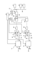
- FIG. 1 is a schematic configuration diagram of a power generation facility to which a generator according to Embodiment 1 of the present invention is applied.
- FIG. 2 is a schematic diagram of a supercharger equipped with the generator of the first embodiment.
- FIG. 3 is a cross-sectional view of the generator according to the first embodiment.
- FIG. 4 is a schematic configuration diagram of a power generation facility to which the generator according to the second embodiment of the present invention is applied.
- FIG. 1 is a schematic configuration diagram of a power generation facility to which a generator according to Embodiment 1 of the present invention is applied
- FIG. 2 is a schematic diagram of a supercharger to which the generator of Embodiment 1 is attached
- FIG. It is sectional drawing of the generator of Example 1.
- the power generation facility of Example 1 is mounted on a ship (not shown). As shown in FIG. 1, the two diesel engines (exhaust gas generation sources) 11 and 31 are driven with heavy oil as fuel and function as propulsion for navigating the ship. That is, in each diesel engine 11, 31, propeller shafts 12, 32 are connected to a crankshaft (not shown), and screw propellers 13, 33 are attached to the propeller shafts 12, 32.
- the two superchargers 14 and 34 are attached to the diesel engines 11 and 31 and are configured by connecting the turbines 15 and 35 and the compressors 16 and 36 by the rotary shafts 17 and 37. Accordingly, when the turbines 15 and 35 are rotated by the exhaust gas discharged from the exhaust passages 18 and 38 of the diesel engines 11 and 31 in the superchargers 14 and 34, the compressors connected by the rotary shafts 17 and 37 are connected.
- the turbochargers 16 and 36 can be supercharged and fed into the intake passages 19 and 39 of the diesel engines 11 and 31.
- the superchargers 14 and 34 are connected to the generators 20 and 40 on the same axis.
- the rotary shafts 21 and 41 are directly connected to the rotary shafts 17 and 37 of the superchargers 14 and 34, respectively. Accordingly, when each of the superchargers 14 and 34 is driven, each of the generators 20 and 40 can output AC power.
- the power converter 51 rectifies and outputs the power generated by each of the generators 20 and 40, and includes converters 22 and 42, a DC link 23, and an inverter 24. That is, the converters 22 and 42 are connected to the generators 20 and 40, and rectify the AC power output from the generators 20 and 40 to convert it into DC power.
- the converters 22 and 42 are connected to the inverter 24 via the DC link 23, and the capacitor 25 is provided on the DC link 23.
- the DC link 23 can charge the DC power converted by the converters 22 and 42 and outputs the DC power stored in the capacitor 25 to the inverter 24.
- the inverter 24 converts the DC power converted by the converters 22 and 42 into predetermined (for example, 60 Hz, 450 V) AC power.
- the power converter 51 rectifies and outputs the power generated by the two generators 20 and 40, and the two converters 22 and 42 are connected to one inverter 24 via the DC link 23. ing.
- the inverter 24 is connected to an output system 26, and a plurality of auxiliary machines 27, 28, 29... Are connected to the output system 26.
- the converter controller 52 can control the converters 22 and 42, and the inverter controller 53 can control the inverter 24.
- the main controller 54 can control the converter controller 52 and the inverter controller 53.
- the main controller 54 outputs a DC bus voltage command to the converter controller 52 and outputs a power generation output command to the inverter controller 53.
- the inverter controller 53 controls the power output from the inverter 24 based on the power generation output command from the main controller 54, and the inverter 24 is supplied with power from the two converters 22 and 42. Therefore, the converter controller 52 controls the converters 22 and 42 so that the DC bus voltage is constant.
- the converter controller 52 can perform power generation output control, output torque control, and rotation speed control for each of the converters 22 and 42.
- the converter controller 52 controls the converters 22 and 42 so that, for example, the power generation output becomes larger with respect to the higher rotational speed of the generators 20 and 40. That is, the converter controller 52 decreases the command rotational speed or increases the command torque for the converter on the generator side having a high rotational speed.
- the converter controller 52 controls each converter 22 and 42 so that a power generation output becomes large with respect to the one where the output torque of the generators 20 and 40 is small, for example. That is, the converter controller 52 decreases the command rotational speed or increases the command torque with respect to the generator-side converter having a small torque.
- each of the converters 22 and 42 is in a voltage PWM format, and a backflow prevention diode is disposed between the DC buses, so that a lateral flow between the parallel converters 22 and 42 can be prevented.
- the converter controller 52 can control the converters 22 and 42 with high accuracy, the backflow prevention diode is not necessary.
- the main controller 54 controls the converters 22 and 42 according to the AC power output from the inverter 24. That is, the main controller 54 controls the converters 22 and 42 so that the AC power output from the inverter 24 is substantially constant.
- the superchargers 14 and 34 and the generators 20 and 40 of the present embodiment will be described in detail, the superchargers 14 and 34 and the generators 20 and 40 have substantially the same configuration. Therefore, only the one supercharger 14 and the generator 20 will be described.
- a rotating shaft 17 is rotatably supported at the center portion of the casing 101, and a turbine 15 is fixed to one end portion of the rotating shaft 17 so as to be integrally rotatable.
- the compressor 16 is fixed so as to be integrally rotatable.
- an exhaust gas passage 102 is formed at one end of the casing 101, and an upstream side of the exhaust gas passage 102 is connected to the diesel engine 11 (see FIG. 1) via the exhaust passage 18.
- the casing 101 has an intake gas passage 103 formed at the other end, and a downstream side of the intake gas passage 103 is connected to the diesel engine 11 (see FIG. 1) via the intake passage 19.
- the generator 20 is disposed at the other end of the casing 101 and closer to the axial center than the intake gas passage 103.
- the generator 20 has a rotation center on a concentric axis with the rotation shaft 17, and a rotation shaft (generator rotation shaft) 111 is directly connected to the rotation shaft 17 of the supercharger 14 via the rotation shaft 21 and can rotate integrally. It has become.
- the generator 20 includes a rotating shaft 111, a rotor 112 fixed to the rotating shaft 111, and a stator 113 provided outside the rotor 112. Is rotatably supported on the casing 101 of the generator 20 by bearings 114 and 115 and is directly connected to the rotating shaft 17.
- the rotor 112 includes an iron core 121 fixed to the rotating shaft 111, a magnet 122 fixed to the outer peripheral surface of the iron core 121 and divided into a plurality of parts in the axial direction, and the magnet 122.
- the holding ring 123 is arranged on the outer peripheral surface and divided into a plurality of parts in the axial direction.
- the iron core 121 has a cylindrical shape and is integrally fixed by being press-fitted into the outer peripheral surface of the rotating shaft 111.
- the rotating shaft 111 and the iron core 121 may be integrally formed.
- the magnet 122 is composed of a plurality (eight in this embodiment) of magnet pieces 122a having the same shape.
- the magnet piece 122a has a ring shape (or an arcuate shape), is set to a predetermined outer diameter and inner diameter, and is set to a predetermined axial length.
- forms a ring shape is comprised by making the eight magnet pieces 122a continue to an axial direction, and this magnet 122 press-fits into the outer peripheral surface of the iron core 121 (or Are fixed together.
- the magnet 122 composed of the eight magnet pieces 122 a is set to have a slightly longer axial length than the iron core 121.
- the retaining ring 123 is composed of a plurality (eight in this embodiment) retaining ring pieces 123a having the same shape.
- the holding ring piece 123a has a ring shape, is set to a predetermined outer diameter and inner diameter, and is set to a predetermined axial length.
- the holding ring 123 which makes ring shape is comprised by making the eight holding ring pieces 123a continue in the axial direction, and this holding ring 123 is pressed into the outer peripheral surface of the magnet 122 so as to be integrated. It is fixed.
- the holding ring 123 including the eight holding ring pieces 123 a is slightly longer in the axial direction than the iron core 121, and is set to the same axial length as the magnet 122.
- the division position that is, the contact position between the magnet pieces 122a and the contact position between the holding ring pieces 123a are made the same.
- the present invention is not limited to this configuration, and the axial division positions of the magnet 122 and the holding ring 123 may be different.
- the division positions can be made different by making the number of divisions of the two different. That is, the magnet 122 may be composed of eight pieces and the holding ring 123 may be composed of seven pieces.
- the stator 113 includes an iron core 131 that is divided into a plurality of parts in the axial direction and forms a ring shape, and a coil 132 that is wound around a slot portion of the iron core 131. That is, the iron core 131 has a cylindrical shape with a slot, and is fixed inside a cylindrical shape (not shown). In this case, although not shown, the iron core 131 is composed of a plurality of thin plate pieces having the same shape. The thin plate piece has a disk shape with a slot, is set to a predetermined outer diameter and inner diameter, and is set to a predetermined axial thickness.
- forms a ring shape is comprised by making a some disk piece continue in an axial direction (thickness direction).
- the iron core 131 made of a plurality of thin plate pieces is set to the same axial length as the magnet 122 and the holding ring 123 of the rotor 112.
- a predetermined number of coils 132 are wound around the iron core 131.
- the number of coil turns is set based on the generator required specification voltage. For example, if the axial length of the generator 20 is doubled, the number of coil turns may be doubled. However, since the current is 1 ⁇ 2, when the same Joule loss is used, the coil wire diameter is 1 ⁇ 2. Thus, the radial dimension does not change.
- the axial lengths of the rotor 112 and the stator 113 are set to the generator required specifications set on the basis of the rotational speed of the supercharger 14 and the power generation possible output of the generator 20.
- the output of the generator 20 is P
- the torque is T
- the angular velocity is ⁇
- P T ⁇ ⁇
- the angular velocity ⁇ is proportional to the rotational speed N. Therefore, since the output P and the angular velocity ⁇ (rotation speed N) of the generator 20 are set as the generator required specifications, it is necessary to satisfy the generator required specifications by adjusting the torque T.
- the adjustment of the torque T is performed by changing the outer diameter and axial length of the generator 20, that is, the rotor 112 and the stator 113. Adjustable. In the present embodiment, the torque T can be adjusted by changing the axial length without changing the outer diameters of the rotor 112 and the stator 113, so that various generator required specifications can be accommodated.
- the magnet piece 122a in the magnet 122, the holding ring piece 123a in the holding ring 123, and the disk piece in the iron core 131 are each set as one unit, and the number corresponding to each axial length is set. That is, only one magnet piece 122a, holding ring piece 123a, and disk piece are manufactured, and the respective numbers are set based on the generator required specification, and the desired magnet 122 corresponding to the generator required specification is held.
- the ring 123 and the iron core 131 can be manufactured.
- the axial lengths of the magnet piece 122a, the holding ring piece 123a, and the disk piece may be set as appropriate, and a plurality of lengths are provided depending on the generator to be applied. In addition, those having different axial lengths may be combined.
- a plurality of generators 20, 40 connected to the feeders 14, 34, a plurality of converters 22, 42 for converting AC power generated by the plurality of generators 20, 40 into DC power, and the plurality of converters 22 , 42 is provided with one inverter 24 that converts the DC power output from the inverter 24 into AC power, and a main controller 54 that controls the converters 22, 42 according to the AC power from the inverter 24.
- inverter 24 only one inverter 24 is required as the power converter 51, and the configuration can be simplified, the space can be saved, and the cost can be reduced. Further, by controlling converters 22 and 42 according to the AC power from inverter 24, stable power can be generated.
- the rotating shaft 111, the rotor 112 fixed to the rotating shaft 111, and the stator 113 provided on the outside of the rotor 112 are configured.
- the magnet 122 and the holding ring 123 constituting the rotor 112 are divided into a plurality of parts in the axial direction, so that the outer diameters of the magnet 122 and the holding ring 123 are made the same according to the required generator specifications.
- the shaft length may be set by setting the number of the divided pieces 122a and 123a to a predetermined number, and the cost can be reduced by standardizing various components.
- the magnet 122 has a ring shape (or an arc shape), a plurality of magnet pieces 122a having the same outer diameter and axial length are provided, the holding ring 123 has a ring shape, and the outer A plurality of retaining ring pieces 123 a having the same diameter and axial length are provided, and are fitted and fixed to the outer peripheral surface of the magnet 122. Therefore, the number of the magnets 122 and the holding ring 123 that constitute the rotor 112 may be set according to the required specifications of the generators 20 and 40 by arranging a plurality of pieces 122a and 123a having the same length. Cost reduction can be achieved by standardizing the constituent members.
- the magnet 122 and the holding ring 123 have different division positions in the axial direction. Therefore, the magnet 122 can be firmly fixed by the holding ring 123 by making the dividing position of the holding ring 123 different from the division position of the magnet 122.
- the stator 113 is composed of an iron core 131 that is divided into a plurality of parts in the axial direction and forms a ring shape, and a coil 132 that is wound around the iron core 131. Therefore, not only the rotor 112 but also the iron core 131 of the stator 113 is divided into a plurality of parts in the axial direction so that the outer diameter of the iron core 131 is the same according to the required specifications of the generators 20 and 40.
- the shaft length may be set by setting the number of divided thin plate pieces as a predetermined number, and the cost can be reduced by standardizing various components.
- FIG. 4 is a schematic configuration diagram of a power generation facility to which the power generator according to the second embodiment of the present invention is applied.
- symbol is attached
- the power generation facility includes two diesel engines 11 and 31, two superchargers 61 and 71, generators 20 and 40, and a power converter 51. is doing.
- the superchargers 61 and 71 of the present embodiment are mounted on the diesel engines 11 and 31, and are configured by connecting the turbines 15 and 35 and the compressors 16 and 36 by the rotary shafts 17 and 37. ing.
- the superchargers 61 and 71 are variable capacity superchargers, and variable nozzle mechanisms (nozzle vanes) 62 and 72 capable of controlling the capacity of exhaust gas introduced into the turbines 15 and 35 are provided. Yes.
- the variable nozzle mechanisms 62 and 72 rotate the drive ring by driving the actuator, whereby the lever plate swings to change the blade angle of the nozzle vane and is introduced into the turbines 15 and 35.
- the capacity of the exhaust gas can be adjusted.
- the compressors connected by the rotary shafts 17 and 37 are connected.
- the turbochargers 16 and 36 can be supercharged and fed into the intake passages 19 and 39 of the diesel engines 11 and 31.
- the capacity of the exhaust gas introduced into the turbines 15 and 35 can be adjusted by the variable nozzle mechanisms 62 and 72, and the intake air amount sent to the diesel engines 11 and 31, that is, the supercharging pressure can be adjusted.
- the superchargers 61 and 71 are connected to the generators 20 and 40 on the same axis.
- the rotary shafts 21 and 41 are directly connected to the rotary shafts 17 and 37 of the superchargers 61 and 71, respectively. Therefore, when each supercharger 61, 71 is driven, each generator 20, 40 can output AC power.
- the power converter 51 rectifies and outputs the power generated by each of the generators 20 and 40, and includes converters 22 and 42, a DC link 23, and an inverter 24.
- the inverter 24 is connected to an output system 26, and a plurality of auxiliary machines 27, 28, 29... Are connected to the output system 26.
- the converter controller 52 can control the converters 22 and 42, and the inverter controller 53 can control the inverter 24.
- the main controller 54 can control the converter controller 52 and the inverter controller 53 and can control the diesel engines 11 and 31 and the superchargers 61 and 71 (variable nozzle mechanisms 62 and 72).
- the main controller 54 outputs a DC bus voltage command to the converter controller 52 and outputs a power generation output command to the inverter controller 53.
- the inverter controller 53 controls the power output from the inverter 24 based on the power generation output command from the main controller 54, and the inverter 24 is supplied with power from the two converters 22 and 42. Therefore, the converter controller 52 controls the converters 22 and 42 so that the DC bus voltage is constant.
- the main controller 54 controls the diesel engines 11 and 31 and the superchargers 61 and 71 (variable nozzle mechanisms 62 and 72) according to the AC power output from the inverter 24. That is, the main controller 54 controls the variable nozzle mechanisms 62 and 72 of the diesel engines 11 and 31 and the superchargers 61 and 71 so that the AC power output from the inverter 24 is substantially constant.
- the main controller 54 controls the inverter controller 53 and the converter controller 52 so that the AC power output from the inverter 24 is substantially constant.
- the driving force of the diesel engines 11 and 31 is also used for the propulsion force of the ship, the driving force fluctuates, and the rotational speed of the generators 20 and 40, that is, the amount of power generation fluctuates.
- the main controller 54 controls the diesel engines 11 and 31 within a range in which the propulsive force of the ship does not fluctuate so that the rotation speed of the generators 20 and 40 does not fluctuate.
- the control contents of the diesel engines 11 and 31 include, for example, the intake air amount, the fuel supply amount, the ignition timing, and the rotation speed.
- the main controller 54 controls the supercharging pressure in the superchargers 61 and 71 within a range where the propulsive force of the ship does not fluctuate so that the rotation speed of the generators 20 and 40 does not fluctuate. That is, the main controller 54 adjusts the volume of exhaust gas introduced into the turbines 15 and 35 by the variable nozzle mechanisms 62 and 72, thereby adjusting the intake air amount that is sent to the diesel engines 11 and 31, that is, the supercharging pressure. .
- the superchargers 61 and 71 described above are of a variable capacity type, other configurations are the same as those of the first embodiment, and the generators 20 and 40 are accommodated therein.
- the generators 20 and 40 have a rotating shaft directly connected to the rotating shafts 17 and 37 of the superchargers 61 and 71, and can rotate integrally.
- the other configurations are the same as those in the first embodiment.
- a plurality of generators 20, 40 connected to the feeders 61, 71, a plurality of converters 22, 42 for converting AC power generated by the plurality of generators 20, 40 into DC power, and the plurality of converters 22 , 42 is provided with one inverter 24 that converts the DC power output from the inverter 24 into AC power, and a main controller 54 that controls the converters 22, 42 according to the AC power from the inverter 24.
- inverter 24 only one inverter 24 is required as the power converter 51, and the configuration can be simplified, the space can be saved, and the cost can be reduced. Further, by controlling converters 22 and 42 according to the AC power from inverter 24, stable power can be generated.
- the main controller 54 controls the plurality of diesel engines 11 and 31 and the plurality of superchargers 61 and 71 according to the AC power from the inverter 24. Therefore, stable power can be generated by controlling the diesel engines 11 and 31 and the superchargers 61 and 71 so that the AC power from the inverter 24 becomes a desired power.
- the main controller 54 can generate stable electric power by controlling the intake air amount, fuel supply amount, ignition timing, rotation speed, and the like of the diesel engines 11 and 31. Further, since the superchargers 61 and 71 are of a variable capacity type, the main controller 54 adjusts the supercharging pressure by controlling the variable nozzle mechanisms 62 and 72 in the superchargers 61 and 71. By controlling the supercharging pressure by adjusting the amount of exhaust gas and the flow velocity, stable electric power can be generated.
- two diesel engines 11 and 31 are applied as a plurality of exhaust gas generation sources and two superchargers 14, 34, 61, and 71 are provided. It is not limited to one and may be three or more.
- the exhaust gas generation source is not limited to the diesel engine, and may be each cylinder in the diesel engine, and a supercharger may be arranged for each cylinder.
- the exhaust gas generation source is not limited to a diesel engine, but may be any one that generates exhaust gas, such as a gas turbine.
- the generator according to the present invention can reduce the cost by standardizing various components by dividing the rotor in the axial direction, and can be applied to any generator and power generation equipment. Can do.
Abstract
Description
14,34,61,71 過給機
20,40 発電機
22,42 コンバータ
23 DCリンク
24 インバータ
51 電力変換器
52 コンバータコントローラ
53 インバータコントローラ
54 メインコントローラ
111 回転軸
112 ロータ
113 ステータ
121 鉄心
122 磁石
122a 磁石ピース(分割ピース)
123 保持リング
123a 保持リングピース(分割ピース)
131 鉄心
132 コイル 11,31 Diesel engine (exhaust gas generation source)
14, 34, 61, 71
123
131
Claims (8)
- 複数の排ガス発生源と、
該複数の排ガス発生源からの排ガスにより駆動する複数の過給機と、
該複数の過給機に接続される複数の発電機と、
該複数の発電機により発電された交流電力を直流電力に変換する複数のコンバータと、
該複数のコンバータから出力された直流電力を交流電力に変換する一つのインバータと、
該インバータからの交流電力に応じて前記複数の排ガス発生源または前記複数の過給機を制御する制御装置と、
を備えることを特徴とする発電設備。 A plurality of exhaust gas sources;
A plurality of superchargers driven by exhaust gases from the plurality of exhaust gas generation sources;
A plurality of generators connected to the plurality of superchargers;
A plurality of converters for converting AC power generated by the plurality of generators into DC power;
One inverter that converts the DC power output from the plurality of converters into AC power;
A control device for controlling the plurality of exhaust gas generation sources or the plurality of superchargers in accordance with AC power from the inverter;
A power generation facility comprising: - 前記複数の排ガス発生源はエンジンであり、前記制御装置は、前記インバータからの交流電力が一定となるように前記エンジンを制御することを特徴とする請求項1に記載の発電設備。 The power generation facility according to claim 1, wherein the plurality of exhaust gas generation sources are engines, and the control device controls the engine so that AC power from the inverter is constant.
- 前記複数の過給機は可変容量式の過給機であり、前記制御装置は、前記インバータからの交流電力が一定となるように前記過給機における過給圧を制御することを特徴とする請求項1に記載の発電設備。 The plurality of superchargers are variable capacity superchargers, and the control device controls a supercharging pressure in the supercharger so that AC power from the inverter is constant. The power generation facility according to claim 1.
- 回転軸と、
該回転軸に固定されるロータと、
該ロータの外側に設けられるステータと、
を備える発電機において、
前記ロータは、
前記回転軸に固定される鉄心と、
該鉄心の外周面に固定されて軸方向に複数に分割される磁石と、
該磁石の外周面に配置されて軸方向に複数に分割される保持リングと、
を有することを特徴とする発電機。 A rotation axis;
A rotor fixed to the rotating shaft;
A stator provided outside the rotor;
In a generator comprising:
The rotor is
An iron core fixed to the rotating shaft;
A magnet fixed to the outer peripheral surface of the iron core and divided into a plurality of parts in the axial direction;
A retaining ring arranged on the outer peripheral surface of the magnet and divided into a plurality of parts in the axial direction;
The generator characterized by having. - 前記磁石は、リング形状または弓形形状をなし、外径と軸方向長さが同じ寸法の分割ピースを有し、前記保持リングは、リング形状をなし、外径と軸方向長さが同じ寸法の分割ピースを有し、前記磁石の外周面に嵌合して固定されることを特徴とする請求項4に記載の発電機。 The magnet has a ring shape or an arcuate shape, and has split pieces having the same outer diameter and axial length, and the retaining ring has a ring shape and has the same outer diameter and axial length. The generator according to claim 4, wherein the generator has a split piece and is fitted and fixed to the outer peripheral surface of the magnet.
- 前記磁石と前記保持リングは、軸方向における分割位置が相違することを特徴とする請求項4または5に記載の発電機。 The generator according to claim 4 or 5, wherein the magnet and the holding ring have different division positions in the axial direction.
- 前記ステータは、軸方向に複数に分割されてリング形状をなす鉄心と、該鉄心に巻き付けられるコイルとを有することを特徴とする請求項4から6のいずれか一つに記載の発電機。 The generator according to any one of claims 4 to 6, wherein the stator includes an iron core which is divided into a plurality of parts in the axial direction and forms a ring shape, and a coil wound around the iron core.
- 複数の排ガス発生源と、
該複数の排ガス発生源からの排ガスにより駆動する複数の過給機と、
該複数の過給機に接続される複数の発電機と、
該複数の発電機により発電された交流電力を直流電力に変換する複数のコンバータと、
該複数のコンバータから出力された直流電力を交流電力に変換する一つまたは複数のインバータと、
を備える発電設備において、
前記発電機は、
前記過給機の回転軸に直結される発電機回転軸と、
該発電機回転軸に固定されるロータと、
該ロータの外側に設けられるステータと、
を備え、
前記ロータは、
前記回転軸に固定される鉄心と、
該鉄心の外周面に固定されて軸方向に複数に分割される磁石と、
該磁石の外周面に配置されて軸方向に複数に分割される保持リングと、
を有することを特徴とする発電設備。 A plurality of exhaust gas sources;
A plurality of superchargers driven by exhaust gases from the plurality of exhaust gas generation sources;
A plurality of generators connected to the plurality of superchargers;
A plurality of converters for converting AC power generated by the plurality of generators into DC power;
One or a plurality of inverters for converting DC power output from the plurality of converters into AC power;
In a power generation facility comprising:
The generator is
A generator rotating shaft directly connected to the rotating shaft of the supercharger;
A rotor fixed to the generator rotating shaft;
A stator provided outside the rotor;
With
The rotor is
An iron core fixed to the rotating shaft;
A magnet fixed to the outer peripheral surface of the iron core and divided into a plurality of parts in the axial direction;
A retaining ring arranged on the outer peripheral surface of the magnet and divided into a plurality of parts in the axial direction;
A power generation facility comprising:
Priority Applications (7)
| Application Number | Priority Date | Filing Date | Title |
|---|---|---|---|
| CN201180041310.2A CN103069691B (en) | 2010-12-27 | 2011-12-16 | Generator and generating equipment |
| KR1020137004304A KR101468342B1 (en) | 2010-12-27 | 2011-12-16 | Generator and power plant |
| US13/818,362 US9163546B2 (en) | 2010-12-27 | 2011-12-16 | Power generator power generation facility |
| EP11853167.2A EP2660954B1 (en) | 2010-12-27 | 2011-12-16 | Generator and power plant |
| KR1020147013587A KR101504082B1 (en) | 2010-12-27 | 2011-12-16 | Power plant |
| DK11853167.2T DK2660954T3 (en) | 2010-12-27 | 2011-12-16 | GENERATOR AND POWER PLANT |
| US14/804,981 US9490680B2 (en) | 2010-12-27 | 2015-07-21 | Power generator power generation facility |
Applications Claiming Priority (4)
| Application Number | Priority Date | Filing Date | Title |
|---|---|---|---|
| JP2010-289839 | 2010-12-27 | ||
| JP2010-289840 | 2010-12-27 | ||
| JP2010289840A JP5374489B2 (en) | 2010-12-27 | 2010-12-27 | Power generation equipment |
| JP2010289839A JP5501949B2 (en) | 2010-12-27 | 2010-12-27 | Power generation equipment |
Related Child Applications (2)
| Application Number | Title | Priority Date | Filing Date |
|---|---|---|---|
| US13/818,362 A-371-Of-International US9163546B2 (en) | 2010-12-27 | 2011-12-16 | Power generator power generation facility |
| US14/804,981 Division US9490680B2 (en) | 2010-12-27 | 2015-07-21 | Power generator power generation facility |
Publications (1)
| Publication Number | Publication Date |
|---|---|
| WO2012090737A1 true WO2012090737A1 (en) | 2012-07-05 |
Family
ID=46382850
Family Applications (1)
| Application Number | Title | Priority Date | Filing Date |
|---|---|---|---|
| PCT/JP2011/079217 WO2012090737A1 (en) | 2010-12-27 | 2011-12-16 | Generator and power plant |
Country Status (6)
| Country | Link |
|---|---|
| US (2) | US9163546B2 (en) |
| EP (1) | EP2660954B1 (en) |
| KR (2) | KR101468342B1 (en) |
| CN (2) | CN103069691B (en) |
| DK (1) | DK2660954T3 (en) |
| WO (1) | WO2012090737A1 (en) |
Cited By (2)
| Publication number | Priority date | Publication date | Assignee | Title |
|---|---|---|---|---|
| WO2014200193A1 (en) * | 2013-06-12 | 2014-12-18 | 주식회사 엘지화학 | Bidirectional power conversion device |
| JP2019030059A (en) * | 2017-07-26 | 2019-02-21 | ファナック株式会社 | Rotator and rotary electric machine |
Families Citing this family (8)
| Publication number | Priority date | Publication date | Assignee | Title |
|---|---|---|---|---|
| DE102013210255A1 (en) * | 2013-06-03 | 2014-12-04 | Siemens Aktiengesellschaft | Device as well as such a comprehensive drive system, especially for ships |
| CN103287562B (en) * | 2013-06-07 | 2016-02-24 | 哈尔滨耦合动力工程技术中心有限公司 | The boats and ships hybrid power system that diesel power generation electric motor is integrated and mixed method |
| CN104533660B (en) * | 2014-12-24 | 2016-12-28 | 深圳智慧能源技术有限公司 | Exhaust gas turbo generator group |
| DE102015209365A1 (en) * | 2015-05-21 | 2016-11-24 | Bosch Mahle Turbo Systems Gmbh & Co. Kg | turbocharger |
| US20170198648A1 (en) * | 2016-01-08 | 2017-07-13 | David E. James | System and method for controlling an operating mode of a motor-generator |
| CN107171494B (en) | 2017-06-15 | 2018-07-20 | 苏州达思灵新能源科技有限公司 | A kind of compressed air turbodynamo system |
| CN109488468B (en) * | 2019-01-08 | 2021-02-05 | 中车株洲电力机车有限公司 | Control method, device, medium and equipment for output power of double internal combustion engine sets |
| KR102529960B1 (en) * | 2021-06-04 | 2023-05-04 | 재단법인 중소조선연구원 | Engine driving system for ship |
Citations (9)
| Publication number | Priority date | Publication date | Assignee | Title |
|---|---|---|---|---|
| JPH06335181A (en) * | 1993-05-25 | 1994-12-02 | Brother Ind Ltd | Rotating electric machine |
| JPH1089017A (en) * | 1996-09-20 | 1998-04-07 | Hitachi Zosen Corp | Power generation facilities and power facilities |
| JPH10243586A (en) * | 1997-02-27 | 1998-09-11 | Hitachi Ltd | Permanent-magnet synchronous motor and its rotor |
| JP2003009537A (en) | 2001-06-27 | 2003-01-10 | Hitachi Ltd | Power converter |
| JP2004080980A (en) * | 2002-08-22 | 2004-03-11 | Hitachi Ltd | System-linking system inverter device |
| JP3699134B2 (en) | 1992-04-13 | 2005-09-28 | ウエスチングハウス・エレクトリック・コーポレイション | Generator design and manufacturing method |
| JP2008286016A (en) * | 2007-05-15 | 2008-11-27 | Nishishiba Electric Co Ltd | Turbocharger generating set |
| JP2009257098A (en) | 2008-04-11 | 2009-11-05 | Mitsubishi Heavy Ind Ltd | Supercharging device |
| JP2010116070A (en) * | 2008-11-13 | 2010-05-27 | Nishishiba Electric Co Ltd | Marine vessel energy system |
Family Cites Families (42)
| Publication number | Priority date | Publication date | Assignee | Title |
|---|---|---|---|---|
| US2655611A (en) * | 1951-01-13 | 1953-10-13 | Whizzer Motor Company | Alternating current generator |
| US3849682A (en) * | 1973-06-19 | 1974-11-19 | Nat Res Dev | Permanent magnet rotor for alternating current generators and motors |
| DE3121607A1 (en) * | 1981-05-30 | 1982-12-23 | Motoren-Werke Mannheim AG vorm. Benz Abt. stationärer Motorenbau, 6800 Mannheim | "SHIP DIESEL ENGINE DRIVE UNIT" |
| EP0141634A3 (en) * | 1983-10-29 | 1986-07-30 | Isuzu Motors Limited | Engine with exhaust energy recovery device and generator device for use with the engine |
| CH667495A5 (en) * | 1985-04-25 | 1988-10-14 | Bbc Brown Boveri & Cie | Booted MARINE DIESEL ENGINE. |
| DE3676280D1 (en) * | 1985-10-19 | 1991-01-31 | Isuzu Motors Ltd | ENERGY RECOVERY DEVICE FOR A CHARGED INTERNAL COMBUSTION ENGINE. |
| JPS6293429A (en) * | 1985-10-19 | 1987-04-28 | Isuzu Motors Ltd | Turbo compound engine |
| CH669977A5 (en) * | 1986-02-27 | 1989-04-28 | Bbc Brown Boveri & Cie | |
| JPS62254649A (en) * | 1986-04-25 | 1987-11-06 | Isuzu Motors Ltd | Generator for turbocharger |
| JPH0627504B2 (en) * | 1986-05-12 | 1994-04-13 | いすゞ自動車株式会社 | Engine energy recovery system |
| DE3711863A1 (en) * | 1987-04-08 | 1988-10-27 | Man B & W Diesel Gmbh | Multiple-engine installation for ships |
| JPH01100318A (en) * | 1987-10-09 | 1989-04-18 | Isuzu Motors Ltd | Control device for turbo-charger with revolving armature |
| JP2640757B2 (en) * | 1988-07-18 | 1997-08-13 | 株式会社いすゞセラミックス研究所 | Control device for turbocharger |
| JPH0650061B2 (en) * | 1988-09-12 | 1994-06-29 | 株式会社いすゞセラミックス研究所 | Supercharger control device |
| JPH0776533B2 (en) * | 1991-07-06 | 1995-08-16 | いすゞ自動車株式会社 | Drive device for turbocharger with rotating electric machine |
| JPH05280362A (en) * | 1992-03-31 | 1993-10-26 | Isuzu Motors Ltd | Voltage control device of dynamo-electric machine for turbocharger |
| JPH06335281A (en) * | 1993-05-21 | 1994-12-02 | Kyocera Corp | Apparatus for controlling power feed to dc multi-phase spindle motor |
| US6259180B1 (en) * | 1996-07-02 | 2001-07-10 | Schlenker Enterprises, Ltd. | Motor including embedded permanent magnet rotor and method for making the same |
| GB2299217B (en) * | 1995-03-23 | 1999-07-07 | Aisin Seiki | Method of assembling a permanent magnet rotor |
| JPH08275470A (en) * | 1995-03-29 | 1996-10-18 | Toshiba Corp | Rotor of permanent-magnet type electric rotating machine and manufacture thereof |
| JPH08312360A (en) * | 1995-05-18 | 1996-11-26 | Isuzu Motors Ltd | Exhaust gas recirculation controller for diesel engine |
| TW380329B (en) * | 1997-04-16 | 2000-01-21 | Japan Servo | Permanent-magnet revolving electrodynamic machine with a concentrated winding stator |
| US6170443B1 (en) * | 1998-09-11 | 2001-01-09 | Edward Mayer Halimi | Internal combustion engine with a single crankshaft and having opposed cylinders with opposed pistons |
| US6611078B1 (en) * | 2000-07-19 | 2003-08-26 | Tri-Seven Research, Inc. | Flux diode motor |
| US20030062792A1 (en) * | 2001-10-03 | 2003-04-03 | Reiter Frederick B. | Manufacturing method and composite powder metal rotor assembly for spoke type interior permanent magnet machine |
| JP3753073B2 (en) * | 2002-01-21 | 2006-03-08 | 株式会社日立製作所 | Permanent magnet rotating electric machine |
| US20030193258A1 (en) | 2002-04-16 | 2003-10-16 | Reiter Frederick B. | Composite powder metal rotor sleeve |
| JP2005344539A (en) | 2004-06-01 | 2005-12-15 | Mitsui Eng & Shipbuild Co Ltd | Air fuel ratio control system for gas engine |
| US7047743B1 (en) * | 2005-03-14 | 2006-05-23 | Deere & Company | Electric turbo compound configuration for an engine/electric generator system |
| CN101713328B (en) * | 2005-10-05 | 2012-05-23 | 曼柴油机和涡轮公司,德国曼柴油机和涡轮欧洲股份公司的联营公司 | Vessel propulsion system |
| US7791237B2 (en) * | 2006-12-19 | 2010-09-07 | General Electric Company | Fault-tolerant synchronous permanent magnet machine |
| DE102006061374B4 (en) * | 2006-12-22 | 2016-12-08 | Siemens Aktiengesellschaft | System for utilizing excess energy in the exhaust gases of a two-stroke large diesel engine |
| JP5030710B2 (en) * | 2007-08-30 | 2012-09-19 | 三菱重工業株式会社 | Steam turbine ship |
| US7980905B2 (en) * | 2007-11-25 | 2011-07-19 | C-Mar Holdings, Ltd. | Method and apparatus for providing power to a marine vessel |
| US7788889B2 (en) * | 2008-06-17 | 2010-09-07 | Deere & Company | Agricultural harvester with dual engines and electrical power coupling |
| US8001771B2 (en) * | 2008-08-08 | 2011-08-23 | Deere & Company | Dual engine work vehicle with control for exhaust aftertreatment regeneration |
| JP5018975B2 (en) * | 2008-12-11 | 2012-09-05 | トヨタ自動車株式会社 | Supercharger control device for internal combustion engine |
| IT1392377B1 (en) * | 2008-12-22 | 2012-03-02 | Energifera S R L | COGENERATION SYSTEM |
| CN102317601B (en) | 2009-02-25 | 2015-03-18 | 三菱重工业株式会社 | Control device for pre-mixing engine |
| US8087900B2 (en) * | 2009-05-22 | 2012-01-03 | Deere & Company | Agricultural harvester with propulsion load shifting between dual engines |
| US9467021B2 (en) * | 2010-02-16 | 2016-10-11 | Sine Waves, Inc. | Engine and induction generator |
| US8783015B2 (en) * | 2011-12-15 | 2014-07-22 | Ecomotors, Inc. | Shared EGR system and method for a dual-module engine |
-
2011
- 2011-12-16 CN CN201180041310.2A patent/CN103069691B/en active Active
- 2011-12-16 WO PCT/JP2011/079217 patent/WO2012090737A1/en active Application Filing
- 2011-12-16 DK DK11853167.2T patent/DK2660954T3/en active
- 2011-12-16 US US13/818,362 patent/US9163546B2/en not_active Expired - Fee Related
- 2011-12-16 KR KR1020137004304A patent/KR101468342B1/en active IP Right Grant
- 2011-12-16 EP EP11853167.2A patent/EP2660954B1/en active Active
- 2011-12-16 KR KR1020147013587A patent/KR101504082B1/en active IP Right Grant
- 2011-12-16 CN CN201510360005.XA patent/CN104948278B/en active Active
-
2015
- 2015-07-21 US US14/804,981 patent/US9490680B2/en active Active
Patent Citations (9)
| Publication number | Priority date | Publication date | Assignee | Title |
|---|---|---|---|---|
| JP3699134B2 (en) | 1992-04-13 | 2005-09-28 | ウエスチングハウス・エレクトリック・コーポレイション | Generator design and manufacturing method |
| JPH06335181A (en) * | 1993-05-25 | 1994-12-02 | Brother Ind Ltd | Rotating electric machine |
| JPH1089017A (en) * | 1996-09-20 | 1998-04-07 | Hitachi Zosen Corp | Power generation facilities and power facilities |
| JPH10243586A (en) * | 1997-02-27 | 1998-09-11 | Hitachi Ltd | Permanent-magnet synchronous motor and its rotor |
| JP2003009537A (en) | 2001-06-27 | 2003-01-10 | Hitachi Ltd | Power converter |
| JP2004080980A (en) * | 2002-08-22 | 2004-03-11 | Hitachi Ltd | System-linking system inverter device |
| JP2008286016A (en) * | 2007-05-15 | 2008-11-27 | Nishishiba Electric Co Ltd | Turbocharger generating set |
| JP2009257098A (en) | 2008-04-11 | 2009-11-05 | Mitsubishi Heavy Ind Ltd | Supercharging device |
| JP2010116070A (en) * | 2008-11-13 | 2010-05-27 | Nishishiba Electric Co Ltd | Marine vessel energy system |
Cited By (3)
| Publication number | Priority date | Publication date | Assignee | Title |
|---|---|---|---|---|
| WO2014200193A1 (en) * | 2013-06-12 | 2014-12-18 | 주식회사 엘지화학 | Bidirectional power conversion device |
| JP2019030059A (en) * | 2017-07-26 | 2019-02-21 | ファナック株式会社 | Rotator and rotary electric machine |
| US10581288B2 (en) | 2017-07-26 | 2020-03-03 | Fanuc Corporation | Rotor and rotary electrical machine |
Also Published As
| Publication number | Publication date |
|---|---|
| CN104948278B (en) | 2017-12-05 |
| KR20130041235A (en) | 2013-04-24 |
| EP2660954A1 (en) | 2013-11-06 |
| US20130147206A1 (en) | 2013-06-13 |
| CN103069691B (en) | 2015-09-02 |
| KR20140072918A (en) | 2014-06-13 |
| US20150326095A1 (en) | 2015-11-12 |
| EP2660954A4 (en) | 2017-07-26 |
| US9490680B2 (en) | 2016-11-08 |
| CN104948278A (en) | 2015-09-30 |
| DK2660954T3 (en) | 2019-04-23 |
| KR101504082B1 (en) | 2015-03-19 |
| US9163546B2 (en) | 2015-10-20 |
| CN103069691A (en) | 2013-04-24 |
| KR101468342B1 (en) | 2014-12-04 |
| EP2660954B1 (en) | 2019-03-06 |
Similar Documents
| Publication | Publication Date | Title |
|---|---|---|
| WO2012090737A1 (en) | Generator and power plant | |
| JP6800189B2 (en) | Turbomachinery with gearbox and integrated electromechanical assembly | |
| US20200227966A1 (en) | Turbomachine | |
| US4769993A (en) | Turbocharger for internal combustion engines | |
| JP5086050B2 (en) | Power generation using an output turbine behind the LPT | |
| CA2676586C (en) | Tandem electric machine arrangement | |
| US20130239568A1 (en) | Turbo Assist | |
| JP2011153583A (en) | Supercharger | |
| CN101205835A (en) | Integrated boost cavity ring generator for turbofan and turboshaft engines | |
| US9115642B2 (en) | Turbocharger provided with an electrical machine for a supercharged internal combustion engine | |
| JP5501949B2 (en) | Power generation equipment | |
| US20220003128A1 (en) | Dual rotor electric machine | |
| JP5374489B2 (en) | Power generation equipment | |
| US20200248616A1 (en) | Electric media gap machine for a compressor and/or turbine, compressor and/or turbine | |
| JP5589759B2 (en) | Electric assist turbocharger | |
| US20220209623A1 (en) | Aircraft propulsion device | |
| EP4096069A1 (en) | Aircraft turbo-alternator | |
| JP5691392B2 (en) | Electric assist turbocharger | |
| JPS60195330A (en) | Turbocharger for internal-combustion engine | |
| RU2614421C1 (en) | Birotating compressor | |
| JP2020056372A (en) | Internal combustion engine | |
| JP2012092800A (en) | Electrically-assisted turbocharger |
Legal Events
| Date | Code | Title | Description |
|---|---|---|---|
| WWE | Wipo information: entry into national phase |
Ref document number: 201180041310.2 Country of ref document: CN |
|
| 121 | Ep: the epo has been informed by wipo that ep was designated in this application |
Ref document number: 11853167 Country of ref document: EP Kind code of ref document: A1 |
|
| ENP | Entry into the national phase |
Ref document number: 20137004304 Country of ref document: KR Kind code of ref document: A |
|
| WWE | Wipo information: entry into national phase |
Ref document number: 13818362 Country of ref document: US Ref document number: 2011853167 Country of ref document: EP |
|
| NENP | Non-entry into the national phase |
Ref country code: DE |