WO2012086933A1 - 2P 선로를 이용한 500Mbps 전송 장치 - Google Patents
2P 선로를 이용한 500Mbps 전송 장치 Download PDFInfo
- Publication number
- WO2012086933A1 WO2012086933A1 PCT/KR2011/008971 KR2011008971W WO2012086933A1 WO 2012086933 A1 WO2012086933 A1 WO 2012086933A1 KR 2011008971 W KR2011008971 W KR 2011008971W WO 2012086933 A1 WO2012086933 A1 WO 2012086933A1
- Authority
- WO
- WIPO (PCT)
- Prior art keywords
- symbol
- symbol vectors
- transmission
- gmii
- data
- Prior art date
- Legal status (The legal status is an assumption and is not a legal conclusion. Google has not performed a legal analysis and makes no representation as to the accuracy of the status listed.)
- Ceased
Links
Images


Classifications
-
- H—ELECTRICITY
- H04—ELECTRIC COMMUNICATION TECHNIQUE
- H04B—TRANSMISSION
- H04B3/00—Line transmission systems
- H04B3/02—Details
-
- H—ELECTRICITY
- H04—ELECTRIC COMMUNICATION TECHNIQUE
- H04L—TRANSMISSION OF DIGITAL INFORMATION, e.g. TELEGRAPHIC COMMUNICATION
- H04L1/00—Arrangements for detecting or preventing errors in the information received
- H04L1/004—Arrangements for detecting or preventing errors in the information received by using forward error control
- H04L1/0056—Systems characterized by the type of code used
- H04L1/0067—Rate matching
-
- H—ELECTRICITY
- H04—ELECTRIC COMMUNICATION TECHNIQUE
- H04L—TRANSMISSION OF DIGITAL INFORMATION, e.g. TELEGRAPHIC COMMUNICATION
- H04L12/00—Data switching networks
- H04L12/28—Data switching networks characterised by path configuration, e.g. LAN [Local Area Networks] or WAN [Wide Area Networks]
- H04L12/2801—Broadband local area networks
-
- H—ELECTRICITY
- H04—ELECTRIC COMMUNICATION TECHNIQUE
- H04L—TRANSMISSION OF DIGITAL INFORMATION, e.g. TELEGRAPHIC COMMUNICATION
- H04L25/00—Baseband systems
- H04L25/02—Details ; arrangements for supplying electrical power along data transmission lines
- H04L25/05—Electric or magnetic storage of signals before transmitting or retransmitting for changing the transmission rate
-
- H—ELECTRICITY
- H04—ELECTRIC COMMUNICATION TECHNIQUE
- H04L—TRANSMISSION OF DIGITAL INFORMATION, e.g. TELEGRAPHIC COMMUNICATION
- H04L25/00—Baseband systems
- H04L25/02—Details ; arrangements for supplying electrical power along data transmission lines
- H04L25/14—Channel dividing arrangements, i.e. in which a single bit stream is divided between several baseband channels and reassembled at the receiver
-
- H—ELECTRICITY
- H04—ELECTRIC COMMUNICATION TECHNIQUE
- H04L—TRANSMISSION OF DIGITAL INFORMATION, e.g. TELEGRAPHIC COMMUNICATION
- H04L25/00—Baseband systems
- H04L25/38—Synchronous or start-stop systems, e.g. for Baudot code
- H04L25/40—Transmitting circuits; Receiving circuits
- H04L25/49—Transmitting circuits; Receiving circuits using code conversion at the transmitter; using predistortion; using insertion of idle bits for obtaining a desired frequency spectrum; using three or more amplitude levels ; Baseband coding techniques specific to data transmission systems
- H04L25/4917—Transmitting circuits; Receiving circuits using code conversion at the transmitter; using predistortion; using insertion of idle bits for obtaining a desired frequency spectrum; using three or more amplitude levels ; Baseband coding techniques specific to data transmission systems using multilevel codes
- H04L25/4919—Transmitting circuits; Receiving circuits using code conversion at the transmitter; using predistortion; using insertion of idle bits for obtaining a desired frequency spectrum; using three or more amplitude levels ; Baseband coding techniques specific to data transmission systems using multilevel codes using balanced multilevel codes
-
- H—ELECTRICITY
- H04—ELECTRIC COMMUNICATION TECHNIQUE
- H04L—TRANSMISSION OF DIGITAL INFORMATION, e.g. TELEGRAPHIC COMMUNICATION
- H04L49/00—Packet switching elements
- H04L49/40—Constructional details, e.g. power supply, mechanical construction or backplane
-
- H—ELECTRICITY
- H04—ELECTRIC COMMUNICATION TECHNIQUE
- H04L—TRANSMISSION OF DIGITAL INFORMATION, e.g. TELEGRAPHIC COMMUNICATION
- H04L47/00—Traffic control in data switching networks
- H04L47/10—Flow control; Congestion control
- H04L47/26—Flow control; Congestion control using explicit feedback to the source, e.g. choke packets
- H04L47/266—Stopping or restarting the source, e.g. X-on or X-off
-
- H—ELECTRICITY
- H04—ELECTRIC COMMUNICATION TECHNIQUE
- H04L—TRANSMISSION OF DIGITAL INFORMATION, e.g. TELEGRAPHIC COMMUNICATION
- H04L5/00—Arrangements affording multiple use of the transmission path
- H04L5/14—Two-way operation using the same type of signal, i.e. duplex
- H04L5/1423—Two-way operation using the same type of signal, i.e. duplex for simultaneous baseband signals
Definitions
- the present invention relates to a 500 Mbps transmission apparatus using a 2P line, and more particularly, to a 500BASE-T transmission apparatus capable of providing 500 mega-class service through a 2P UTP cable based on 1000BASE-T.
- UDTV Ultra Definition TV
- HDTV High Definition TV
- IPTV Internet TV
- 1000BASE-T is valid, exceeding 100 megabytes of UTP transmission technology.
- 1000BASE-T is an IEEE 802.3ab specification that enables 1 Gbps through 4P (4 Pairs) UTP.
- the problem is that UPT installed in most residential areas in Korea is composed of 2P or less. In these areas, a 100 mega Ethernet service using 2P UTP is easy, but there is a problem in providing 1 Gigabit Ethernet using 4P UTP.
- UBcN Ultra Broadband convergence Network
- FTTH-R Real
- DSL Digital Subscriber Line
- Ethernet technology has exploded in demand since it was introduced for office automation, making it a widely used technology in campuses, businesses, and homes.
- Coaxial cable, UTP, and optical cable are used for transmission media.
- UTP technology is used starting from 10 Mbps to 100 Mbps to 1 Gbps.
- 10BASE-T is compatible with 100BASE-T and 100BASE-T is compatible with 1000BASE-T, but 1000BASE-T is fundamentally different. That is, compared to 100 Mbps, instead of simply increasing the transmission rate of symbols, instead of maintaining the same baud rate of 125 MHz, a binary signal is used instead of binary data, and It uses 4P, but simultaneously transmits and receives every 1P (transmitting data in both directions) and ultimately transmits 1Gbps by transmitting 250Mbps per 1P.
- the present invention adds a sub-layer for serializing / parallelizing symbols by matching speed and maintaining synchronization while maintaining a unique hierarchy of 1000BASE-T, thereby providing a service of 500 megabytes through 2P UTP cable.
- the purpose of the present invention is to provide a 500 Mbps transmission apparatus.
- An apparatus of the present invention is a 500 Mbps transmission apparatus using a 2P line, comprising: speed matching means for matching speed to match 0.5 GMII of transmission data input from GMII (Gigabit Media Independent Interface); Data conversion means for generating four symbol vectors using the transmission data whose speed is matched by the speed matching means and generating received data using the four symbol vectors paralleled by the symbol vector processing means; The symbol vector processing means for serializing the four symbol vectors generated by the data converting means into two symbol vectors and parallelizing the two symbol vectors received from the communication means into four symbol vectors; And communication means for transmitting two symbol vectors serialized by the symbol vector processing means to a hybrid circuit, and transferring the two symbol vectors received from the hybrid circuit to the symbol vector processing means.
- speed matching means for matching speed to match 0.5 GMII of transmission data input from GMII (Gigabit Media Independent Interface)
- Data conversion means for generating four symbol vectors using the transmission data whose speed is matched by the speed matching means and generating received data using the four symbol
- the present invention as described above, by adding a sub-layer for serializing / parallelizing the symbols to match the speed and maintain synchronization while maintaining the inherent hierarchical structure of 1000BASE-T, it is possible to provide 500 mega services through 2P UTP cable It is effective.
- the present invention is a 500BASE-T technology that provides a 500 mega-level service through 2P UTP, by adding a sub-layer without changing the 1000BASE-T technology, it is fully compatible with GMII (Gigabit Media Independent Interface).
- GMII Gigabit Media Independent Interface
- the present invention is convertible to 250BASE-T technology capable of transmitting at 250 megabytes in 1P.
- the 2P 500 Mega transmission method or 1P 250 Mega transmission method of the present invention not only provides a transmission rate capable of transmitting a plurality of 3DTV or UDTV channels to be introduced in the future, but also very advantageous in terms of technology provision price, the government promotes It is likely to be actively adopted and used for a considerable period of time in UBcN projects.
- the present invention can provide a UBcN service in the FTTH-E method, there is an advantage that can reduce the cost compared to the FTTH-R.
- 1 is an overall configuration diagram of an embodiment of a 500 Mbps transmission apparatus using a 2P line according to the present invention
- FIG. 2 is a detailed configuration diagram of an embodiment of a 500 Mbps transmission apparatus using a 2P line according to the present invention
- FIG. 3 is an exemplary diagram illustrating a process in which TX_EN (Transmit Enable) of GMII is mapped to 0.5 GMII.
- FIG. 4 is another exemplary diagram illustrating a process in which TX_EN (Transmit Enable) of GMII is mapped to 0.5 GMII;
- TX_EN Transmit Enable
- FIG. 6 is a configuration diagram of one embodiment of the S & S sublayer according to the present invention.
- 1 is an overall configuration diagram of a 500 Mbps transmission apparatus using a 2P line according to the present invention, and shows a 500BASE-T hierarchical structure based on a 1000BASE-T layer.
- the 500 Mbps transmission apparatus using the 2P line according to the present invention maintains a hierarchical structure unique to 1000BASE-T.
- a Rate Adaptation (RA) sublayer 10 is located between the Gigabit Media Independent Interface (GMII) and the PCS layer 20 present in 1000BASE-T, and an S & S (SERDES) is provided between the PCS layer 20 and the PMA layer 40.
- RA Rate Adaptation
- SERDES S & S
- Synchronization sublayer 30 is located.
- the RA sublayer 10 is a sublayer that changes the signal (transmission data) input from GMII to 0.5 GMII and performs a speed matching function. This is because it transmits 250 Mbps to each 1P with 2P UTP, so we need to reduce 1000 Mbps to 500 Mbps.
- the S & S sublayer 30 serializes four symbol vectors A n , B n , C n and D n input from the PCS layer 20 into two symbol vectors P n and Q n , and conversely, PMA.
- the two symbol vectors input from the layer 40 are parallelized to the original four symbol vectors. This process is synchronized.
- the reason for serializing the two symbol vectors is to transmit by 2P UTP.
- FIG. 2 is a detailed configuration diagram of an embodiment of a 500 Mbps transmission apparatus using a 2P line according to the present invention.
- the RA sublayer (speed matching unit) 10 includes a transmit buffer 11, a receive buffer 12, and a controller 13.
- the controller 13 stores the transmission data TXS ⁇ 7: 0> input from GMII in the transmission buffer 11 to reduce 1 Gbps to 500 Mbps.
- the transmission buffer 11 has a length sufficient to buffer a frame flowing at a speed of 1 Gbps, and may be implemented using dual-ported RAM (DPRAM) or First In First Out (FIFO).
- DPRAM dual-ported RAM
- FIFO First In First Out
- the speed stored in the transmission buffer 11 uses a 125 MHz clock
- the speed of transmitting a frame from the transmission buffer 11 uses a 62.5 MHz clock.
- the controller 13 performs EC (Enable Control) to increase the efficiency of the line instead of simply changing the clock.
- EC Enable Control
- the speed of decoupling occurs at 500 Mbps by minimizing the length of IFG when transmitted to 0.5 GMII. The description thereof will be described in detail below.
- the controller 13 receives 0.5 GMII received data (RXD ⁇ 7: 0>) from the PCS receiver 22 as a 62.5 MHz clock, stores it in the reception buffer 12 for a while, and then transfers the GMII to the 125 MHz clock. do. At this time, the controller 13 reads the counter and transmits one or more frames if there is one, attaches a preamble, and adjusts the length of the IFG according to the GMII standard.
- the controller 13 transmits a pause frame to the transmitting side requesting to stop data transmission when the free space of the transmission buffer 11 exceeds the threshold.
- the PCS layer (data converter) 20 includes a PCS transmitter 21 and a PCS receiver 22, and follows the functions suggested by the 1000BASE-T standard.
- the PCS transmitter 21 generates code groups A n , B n , C n , and D n to be transmitted to the S & S sublayer 30 through 'PMA_UNIT_DATA.request' in each symbol period. That is, the PCS transmitter 21 uses the 4D-PAM5 (Pulse Amplitude Modulation 5) technique to transmit the transmitted data TXD ⁇ 7: 0> into four binary symbol vectors A n , B n , C n , and D n. ). In this case, the preamble is replaced with a start stream delimiter (SSD). In addition, since the processing speed must operate at 62.5 MHz, the original symbol period is changed from 8 ns to 16 ns.
- 4D-PAM5 Pulse Amplitude Modulation 5
- the PCS transmitter 21 has three operation modes, a 'SEND_Z' mode for sending a zero vector to the S & S sublayer 30, a training mode for sending an idle signal (SEND_I), and a normal mode for sending and receiving data (SEND_N). ).
- the PCS receiver 22 receives the code group A n , B n , C n , D n from the S & S sublayer 30 through 'PMA_UNIT_DATA.Indication' and uses an inverse transform table (not shown). To generate the received data RXD ⁇ 7: 0>.
- the S & S sublayer (symbol vector processor) 30 converts four symbol vectors A n , B n , C n , and D n input from the PCS layer 20 into two symbol vectors P n and Q. n ), and a serializer 31 for serializing the two symbol vectors inputted from the PMA layer 40 into the original four symbol vectors.
- the PMA layer (communication unit) 40 includes a PMA transmitter 41 and a PMA receiver 42.
- the PMA transmitter 41 receives two symbol vectors from the serializer 31 of the S & S sublayer 30 and transmits the two symbol vectors to two hybrid circuits, respectively.
- the PMA receiver 42 receives two symbol vectors from the two hybrid circuits and delivers the two symbol vectors to the parallelizer 32 of the S & S sublayer 30.
- the hybrid circuit performs two-way transmission and reception at 250 Mbps for each 1P with 2P UTP.
- controller 13 of the RA layer 10 will be described in more detail with reference to FIGS. 3 to 5.
- Represents the time interval of any n th frame Denotes a time interval of an IFG (Inter Frame Gap) of the nth frame, Represents the time interval of the frame when the n-th frame is delivered to 0.5 GMII, Denotes a time interval of the IFG of the corresponding frame.
- the unit is byte time.
- the frame length is the same in bytes, but since GMII operates at 125 MHz and 0.5 GMII operates at 62.5 MHz, the frame time at 0.5 GMII is twice as long as the frame time at GMII. That is, when T (x) is defined as a function representing an absolute time with respect to the byte time x, the following Equation 1 is satisfied.
- the nth frame is transmitted in 0.5 GMII.
- the length of the IFG of the n + 1 th frame is (Where 24 is the number of clocks), this is the case where frames are delivered below 500 Mbps, where the n + 1 th frame is delivered without delay.
- the controller 13 The length (in bytes) of the IFG to satisfy Reduce within range to improve link efficiency.
- the length of the IFG of the n + 1 th frame is In this case, the frame is transmitted at 500 Mbps, and TX_EN of the n + 1 th frame can be generated without delay. That is, since the transmission start point of the n + 1 th frame of GMII and the transmission start point of the n + 1 th frame of 0.5 GMII are exactly the same, the n + 1 th frame can be transmitted immediately without delay. At this time, the controller 13 sets the length of the IFG as the minimum length. Set to.
- the length of the IFG of the n + 1 th frame is Is a case in which frames are delivered in excess of 500 Mbps, the n + 1 th frame must be buffered and occurs with TX_EN delayed. This is because the n + 1 th frame has occurred in GMII before transmitting the n th frame in 0.5 GMII.
- the controller 13 is a minimum length of the IFG Set to.
- GMII is entering frames above 500 Mbps. If it exceeds 500 Mbps in a moment, if the flow rate is 500 Mbps on average, if the length of the transmission buffer 11 is sufficiently secured, frame loss can be prevented. However, if the frame rate continuously exceeds 500 Mbps, a large amount of frame loss occurs, so a method to prevent this is necessary.
- the controller 13 performs a flow control (FC). As described above, if the frames are continuously introduced at a speed of 500 Mbps or more while maintaining the minimum IFG through GMII, no matter how large the length of the transmission buffer 11 is, frame loss occurs. Therefore, the controller 13 transmits a pause frame to the transmitting side so that the frame is no longer delivered when the length of the transmission buffer 11 is increased to some extent.
- FC flow control
- Flow control is part of the 802.3x specification. This creates a 'back-pressure' on the network, which reduces the traffic overload on the port.
- the destination MAC address is reserved to use 01-80-C2-00-00-01 when sending a pause frame.
- the opcode for MAC control is 0x0001.
- the period for requesting interruption of transmission can be set from 0 to 65,535 in bit time units.
- the S & S sublayer 30 includes a serializer 31 and a parallelizer 32.
- the serialization unit to (4D-to-2D Serializer) (31) comprises four symbol vectors (A n, B n, C n, D n) (A n, B n) in a P n, (C n, Serialize D n ) to Q n .
- the parallelizer 32 must restore P n and Q n input from the PMA receiver 42 to (A n , B n ) and (C n , D n ), respectively. Therefore, it is very important to find the motive of symbol vector. That is, it is necessary to identify whether a symbol flowing at a moment in P n is A n or B n . Similarly, at Q n, at any moment, the incoming symbol should be identified as C n or B n .
- the parallelizer 32 includes a first parallelizer 321, a delay unit 322, a second parallelizer 323, and a synchronization detector 324.
- the first parallelizer (2D-to-4D De-Serializer 1) 321 parallelizes two symbol vectors input from the PMA receiver 42 into four symbol vectors.
- the delay unit 322 delays two symbol vectors input from the PMA receiver 42 by one clock.
- a second parallelizer (2D-to-4D De-Serializer 2) 323 parallelizes two symbol vectors delayed by one clock by the delay unit 322 into four symbol vectors.
- the sync detector 324 detects sync using an Idle symbol vector transmitted in the IFG section. In this case, the sync detector 324 detects the sync in the IFG section in which the Idle symbol vector is introduced, not in the frame (data) section.
- each symbol has a random value among voltage values of ⁇ +2, +1, 0, -1, -2 ⁇ , but the Idle symbol vector has only a voltage value of ⁇ 0, -2 ⁇ .
- the Idle symbol vector has a pattern in which the order of voltage change is constant.
- the sync detector 324 detects sync based on the voltage pattern of the Idle symbol vector transmitted in the IFG period.
- the synchronization detector 324 transfers the symbols output from the first parallelizer 321 to the PCS receiver 22 when the synchronization of the symbols output from the first parallelizer 321 is correct, and the first parallelizer 321. If the synchronization of the symbols output from the () is not matched, the symbol output from the second parallelizer 323 is transmitted to the PCS receiver 22. In this case, at least one of symbols output from the first parallelizer 321 and symbols output from the second parallelizer 323 is synchronized.
- the sequence of symbols output from the first parallelizer 321 is A n , B n , A n + 1 , B n + 1 ,. If it is equal to (satisfy voltage pattern of idle symbol vector), synchronization is correct.
- the sequence of symbols delayed by the delay 322 is B n , A n + 1 , B n + 1 , A n + 2 ,. Same as
- the sequence of symbols output from the first parallelizer 321 is B n , A n + 1 , B n + 1 , A n + 2 ,... If it is equal to (unsatisfactory voltage pattern of idle symbol vector), the synchronization is not correct.
- the sequence of symbols delayed by the delay 322 is A n + 1 , B n + 1 , A n + 2 , B n + 2 .
- the synchronization detector 324 transfers the symbols output from the second parallelizer 323 to the PCS receiver 22 because the symbols output from the second parallelizer 323 are synchronized.
- the synchronization detector 324 detects synchronization using an Idle symbol vector (Idle signal) even in a startup sequence to perform an initial synchronization process.
- the master operates in Mode_1 to transmit an Idle signal, and the slave maintains Mode_Z.
- the master converges the operation of the echo canceller and the crosstalk canceller, and the slave stabilizes the operation of the filter and the equalizer. This is the same as the initialization process of 1000BASE-T.
- the slave performs the synchronization process using the Idle signal from the master.
- the master performs the synchronization process using the Idle signal from the slave.
- the master and the slave operate in Mode_1 to acquire timing and phase synchronization.
- the present invention is applicable to a system that provides a 500 mega-class service through a 2P UTP cable.
Landscapes
- Engineering & Computer Science (AREA)
- Computer Networks & Wireless Communication (AREA)
- Signal Processing (AREA)
- Power Engineering (AREA)
- Physics & Mathematics (AREA)
- Spectroscopy & Molecular Physics (AREA)
- Communication Control (AREA)
- Cable Transmission Systems, Equalization Of Radio And Reduction Of Echo (AREA)
- Synchronisation In Digital Transmission Systems (AREA)
Abstract
본 발명은 2P 선로를 이용한 500 Mbps 전송 장치에 관한 것으로, 1000BASE-T 고유의 계층 구조를 유지하면서 속도를 정합하고 동기를 맞춰 심벌을 직렬화/병렬화하는 부계층을 추가함으로써, 2P UTP 케이블을 통해 500 메가급 서비스를 제공할 수 있도록 하는, 2P 선로를 이용한 500 Mbps 전송 장치를 제공하고자 한다.
Description
본 발명은 2P 선로를 이용한 500 Mbps 전송 장치에 관한 것으로, 더욱 상세하게는 1000BASE-T 기반으로 2P UTP 케이블을 통해 500 메가급 서비스를 제공할 수 있도록 하는 500BASE-T 전송 장치에 관한 것이다.
UDTV(Ultra Definition TV)의 화질은 HDTV(High Definition TV)의 화질에 비해 최소 4배에서 최대 16배까지 높다. 이는 곧 UDTV는 HDTV에 비해 4 ~ 16 배의 전송률로 데이터를 전송해야 함을 의미한다. 이와 더불어 3D 영상이 각광받게 됨에 따라 IPTV(Internet TV)를 통해 UDTV 영상은 물론 3D(3 Dimension) 영상을 전송해야 할 상황이 도래할 것이다. 그러나 현재 UTP(Unshielded Twisted Pair)를 통해 가정에 공급되는 최대 전송률은 이더넷 전송기술의 100 Mbps로서, 상기 서비스를 다수의 채널로 동시에 제공하기에는 턱없이 부족하다.
상기 서비스를 원활하게 제공하기 위해서 다양한 FTTH(Fiber-To-The-Home) 기술을 고려할 수 있으나, 이는 최근에 건축되었거나 새로 건축하는 주거지역에서는 용이하지만 기존의 주거지역에서는 포설이 용이하지 않고 경제적인 문제까지 고려할 때, 여전히 UTP를 활용해야만 하는 상황에 직면하게 된다.
현재까지 UTP를 활용하는 전송기술 중에서 100 메가를 초과하는 것으로 1000BASE-T가 유효하다. 1000BASE-T는 IEEE 802.3ab 규격으로 4P(4 Pairs)의 UTP를 통해 1 Gbps를 가능하게 하는 기술이다. 문제는 국내에서 대부분의 주거지역에 포설된 UPT 현황을 살펴보면 2P 이하로 구성되어 있다는 것이다. 이러한 지역에서는 2P UTP를 사용하는 100 메가 이더넷 서비스는 용이하지만 4P UTP를 사용하는 1 기가 이더넷을 제공하는데 문제가 따른다.
이를 해결하기 위해서는 새로 2P의 UTP를 추가로 설치해야 하는데 구내 배선이 용이하지 않을 뿐만 아니라 추가적인 비용도 만만치 않다.
한편, UBcN(Ultra Broadband convergence Network, 초광대역통합망)은 유선분야에 대해서 최대 1 Gbps까지, 무선분야에 대해서 최대 10 Mbps까지 전송속도를 제공하는 방송통신망 고도화 계획이다. 유선분야에서 1 기가급 서비스를 제공하기 위해서는, 가입자 댁내까지 직접 광케이블을 연결하는 FTTH-R(Real) 방식과, 아파트 동 단자함까지는 광케이블로 연결하고 가입자 댁내까지는 UTP로 연결하여 1000BASE-T 기술을 적용하는 FTTH-E 방식이 가능하다.
UBcN에서 추구하는 바와 같이 100 Mbps를 초과하는 전송률을 UTP를 통해 구현하기 위해서는 DSL(Digital Subscriber Line) 기술을 선택할 수 없다. 왜냐하면 가장 높은 전송률을 제공하는 VDSL(Very High bit rate DSL)조차도 100 Mbps 이하이기 때문이다. 따라서, 유일한 대안으로 선택할 수 있는 것이 기가급의 이더넷이다.
이더넷 기술은 사무 자동화를 위해 도입된 이래로 폭발적으로 수요가 증가하여 캠퍼스와 사업장은 물론이고 일반 가정에도 널리 사용되는 기술로 자리잡고 있다. 전달 매체는 동축케이블, UTP, 광케이블이 사용되고 있으며 그 중에서도 UTP를 활용하는 기술은 10 Mbps에서 시작하여 100 Mbps를 거쳐 1 Gbps에 이르고 있다.
10BASE-T는 100BASE-T와 호환되고, 100BASE-T는 1000BASE-T와 호환되나, 1000BASE-T는 근본적으로 다른 기술이 적용되고 있다. 즉, 100 Mbps와 비교하면 단순히 심벌의 전송속도를 증가시키는 것이 아니라, 125 MHz의 동일한 보드율(baud rate)를 유지하는 대신 2진 데이터를 사용하지 않고 5진(quinary) 신호를 사용하며, 또한 4P를 사용하되 1P마다 송신과 수신을 동시에 수행하여(양방향으로 데이터를 전송) 궁극적으로 1P마다 250 Mbps를 전송함으로써 전체적으로 1Gbps를 전송한다.
이러한 기가급 이더넷은 4P의 UTP 케이블이 있어야 하나, 현재 대부분의 주거 지역에는 2P UTP 케이블이 포설되어 있어 10 Mbps 또는 100 Mbps의 서비스만 가능하다.
결국, FTTH-R을 이용하지 않고서는 아파트를 포함하여 현존하는 많은 주거지역에 UBcN을 제공하는 것이 용이하지 않다. UTP를 추가적으로 설치하는 것을 고려할 수 있으나 이는 값비싼 공사비용을 초래하고, 아울러 공사기간이 길어지면 서비스를 도입하는데 지연이 발생하게 된다.
따라서, 2P의 UTP를 이용하여 UBcN 서비스를 제공할 수 있도록 하는 새로운 기술이 요구된다.
본 발명은 1000BASE-T 고유의 계층 구조를 유지하면서 속도를 정합하고 동기를 맞춰 심벌을 직렬화/병렬화하는 부계층을 추가함으로써, 2P UTP 케이블을 통해 500 메가급 서비스를 제공할 수 있도록 하는, 2P 선로를 이용한 500 Mbps 전송 장치를 제공하는데 그 목적이 있다.
본 발명의 장치는, 2P 선로를 이용한 500 Mbps 전송 장치에 있어서, GMII(Gigabit Media Independent Interface)로부터 입력되는 송신 데이터를 0.5 GMII에 부합하도록 속도를 정합시키는 속도 정합수단; 상기 속도 정합수단에 의해 속도가 정합된 송신 데이터를 이용하여 4개의 심벌벡터를 생성하고, 심벌벡터 처리수단에 의해 병렬화된 4개의 심벌벡터를 이용하여 수신 데이터를 생성하는 데이터 변환수단; 상기 데이터 변환수단에 의해 생성된 4 개의 심벌벡터를 2개의 심벌벡터로 직렬화하고, 통신수단으로부터 전달받은 2개의 심벌벡터를 4개의 심벌벡터로 병렬화하는 상기 심벌벡터 처리수단; 및 상기 심벌벡터 처리수단에 의해 직렬화된 2개의 심벌벡터를 하이브리드 회로로 전달하고, 상기 하이브리도 회로로부터 전달받은 2개의 심벌벡터를 상기 심벌벡터 처리수단으로 전달하는 상기 통신수단을 포함한다.
상기와 같은 본 발명은, 1000BASE-T 고유의 계층 구조를 유지하면서 속도를 정합하고 동기를 맞춰 심벌을 직렬화/병렬화하는 부계층을 추가함으로써, 2P UTP 케이블을 통해 500 메가급 서비스를 제공할 수 있도록 하는 효과가 있다.
또한, 본 발명은 2P UTP를 통해 500 메가급 서비스를 제공하는 500BASE-T 기술로서, 1000BASE-T 기술을 변경하지 않고 부계층을 추가함으로써, GMII(Gigabit Media Independent Interface)와 완전히 호환된다.
또한, 본 발명은 1P로 250 메가로 전송할 수 있는 250BASE-T 기술로 전환 가능하다.
또한, 본 발명의 2P 500 메가 전송 방식 또는 1P 250 메가 전송 방식은 추후에 등장할 3DTV나 UDTV 채널을 복수 개로 전송할 수 있는 전송률을 제공할 뿐만 아니라, 기술 제공 가격 측면에서도 매우 유리한 방식이므로 정부가 추진하고 있는 UBcN 사업에 적극적으로 채택되어 상당한 기간 동안 활용될 가능성이 있다.
또한, 본 발명은 FTTH-E 방식으로 UBcN 서비스를 제공할 수 있도록 하여, FTTH-R에 비해 비용을 절감할 수 있는 장점이 있다.
도 1 은 본 발명에 따른 2P 선로를 이용한 500 Mbps 전송 장치의 일실시예 전체 구성도,
도 2 는 본 발명에 따른 2P 선로를 이용한 500 Mbps 전송 장치의 일실시예 상세 구성도,
도 3 은 GMII의 TX_EN(Transmit Enable)이 0.5 GMII로 매핑되는 과정을 나타내는 일예시도,
도 4 는 GMII의 TX_EN(Transmit Enable)이 0.5 GMII로 매핑되는 과정을 나타내는 다른 예시도,
도 5 는 GMII에서 TX_EN(Transmit Enable)이 0.5 GMII로 매핑되는 과정을 나타내는 또 다른 예시도이다.
도 6 은 본 발명에 따른 S&S 부계층의 일실시예 구성도,
도 7 은 본 발명에 따른 초기화 과정에 대한 일예시도이다.
도 1 은 본 발명에 따른 2P 선로를 이용한 500 Mbps 전송 장치의 일실시예 전체 구성도로서, 1000BASE-T 계층을 기반으로 하는 500BASE-T 계층 구조를 나타낸다.
도 1에 도시된 바와 같이, 본 발명에 따른 2P 선로를 이용한 500 Mbps 전송 장치는 1000BASE-T 고유의 계층 구조를 유지한다. 1000BASE-T에 존재하는 GMII(Gigabit Media Independent Interface)와 PCS 계층(20) 사이에 RA(Rate Adaptation) 부계층(10)이 위치하고, PCS 계층(20)과 PMA 계층(40) 사이에 S&S(SERDES & Synchronization) 부계층(30)이 위치한다.
RA 부계층(10)은 GMII로부터 입력되는 신호(송신 데이터)를 0.5 GMII로 변경하는 부계층으로서, 속도 정합 기능을 수행한다. 이는 2P의 UTP를 가지고 각 1P에 250 Mbps를 전송하므로 1000 Mbps를 500 Mbps로 줄여야 하기 때문이다.
S&S 부계층(30)은 PCS 계층(20)으로부터 입력되는 4 개의 심벌벡터(An, Bn, Cn, Dn)를 2개의 심벌벡터(Pn, Qn)로 직렬화하고, 반대로 PMA 계층(40)으로부터 입력되는 2개의 심벌벡터를 원래의 4개의 심벌벡터로 병렬화한다. 이러한 과정은 동기를 맞춰 이루어진다. 여기서, 2개의 심벌벡터로 직렬화하는 이유는 2P의 UTP로 송신하기 위함이다.
도 2 는 본 발명에 따른 2P 선로를 이용한 500 Mbps 전송 장치의 일실시예 상세 구성도이다.
도 2에 도시된 바와 같이, 먼저 RA 부계층(속도 정합부)(10)은 송신 버퍼(11), 수신 버퍼(12), 및 제어기(13)를 포함한다.
제어기(13)는 1 Gbps를 500 Mbps로 줄이기 위해 GMII로부터 입력되는 송신 데이터(TXS<7:0>)를 송신 버퍼(11)에 저장한다. 송신 버퍼(11)는 1 Gbps의 속도로 유입되는 프레임을 완충할 수 있도록 충분한 길이를 갖으며, DPRAM(Dual-Ported RAM)이나 FIFO(First In First Out)를 이용하여 구현할 수 있다. 이때, 송신 버퍼(11)에 저장되는 속도는 125 MHz 클럭을 사용하고, 송신 버퍼(11)에서 프레임을 송출하는 속도는 62.5 MHz 클럭을 사용한다.
제어기(13)는 단순히 클럭을 변경하는 것이 아니라 선로의 효율을 높이기 위해 EC(Enable Control)을 수행한다. 즉, GMII로부터 유입되는 이더넷 프레임의 IFG(Inter Frame Gap)를 그대로 0.5 GMII로 매핑시키는 것이 아니라, 0.5 GMII로 송출될 때 IFG의 길이를 최소화하여 500 Mbps로 효율적인 속도 디커플링(decoupling)이 일어나게 한다. 이에 대한 설명은 하기에서 상세히 언급하기로 한다.
제어기(13)는 PCS 수신부(22)로부터 0.5 GMII의 수신 데이터(RXD<7:0>)를 62.5 MHz의 클럭으로 수신하여 수신 버퍼(12)에 잠시 저장했다가 GMII로 125 MHz의 클럭으로 전달한다. 이때, 제어기(13)는 카운터를 읽고 1개 이상의 프레임이 있으면 전달하며, 프리앰블(preamble)을 달아주고 IFG의 길이를 GMII의 규격에 맞게 조절한다.
제어기(13)는 송신 버퍼(11)의 여유 공간이 임계치를 초과하면 데이터 송신의 중지를 요청하는 중지(pause) 프레임을 송신측으로 전송한다.
다음으로, PCS 계층(데이터 변환부)(20)은 PCS 송신부(21)와 PCS 수신부(22)를 포함하며, 1000BASE-T의 규격에서 제시하는 기능을 그대로 따른다.
PCS 송신부(21)는 각 심벌 주기에서 'PMA_UNIT_DATA.request'를 통해 S&S 부계층(30)으로 전달할 코드그룹(An, Bn, Cn, Dn)을 생성한다. 즉, PCS 송신부(21)는 4D-PAM5(Pulse Amplitude Modulation 5) 기법을 이용하여 송신 데이터(TXD<7:0>)를 4개의 5진 심벌벡터(An, Bn, Cn, Dn)로 부호화한다. 이때, 프리앰블은 SSD(Start Stream Delimiter)로 치환된다. 아울러, 처리 속도가 62.5 MHz로 동작해야 하기 때문에 원래의 심벌주기가 8 ns에서 16 ns로 변경된다.
PCS 송신부(21)는 3가지의 동작 모드로서, S&S 부계층(30)에 제로(zero) 벡터를 보내는 'SEND_Z' 모드, Idle 신호를 보내는 트레이닝 모드(SEND_I), 데이터를 주고 받는 정상 모드(SEND_N)를 포함한다.
PCS 수신부(22)는 S&S 부계층(30)으로부터 'PMA_UNIT_DATA.Indication'을 통해 코드그룹(An, Bn, Cn, Dn)을 수신하여 역변환 테이블(도면에는 도시되어 있지 않음)을 이용하여 수신 데이터(RXD<7:0>)를 생성한다.
다음으로, S&S 부계층(심벌벡터 처리부)(30)은 PCS 계층(20)으로부터 입력되는 4 개의 심벌벡터(An, Bn, Cn, Dn)를 2개의 심벌벡터(Pn, Qn)로 직렬화하는 직렬화부(31), 및 PMA 계층(40)으로부터 입력되는 2개의 심벌벡터를 원래의 4개의 심벌벡터로 병렬화하는 병렬화부(32)를 포함한다.
다음으로, PMA 계층(통신부)(40)은 PMA 송신부(41), 및 PMA 수신부(42)를 포함한다.
PMA 송신부(41)는 S&S 부계층(30)의 직렬화부(31)로부터 2개 심벌벡터를 전달받아 2개의 하이브리드 회로(Hybrid circut)로 각각 전달한다.
PMA 수신부(42)는 2개의 하이브리드 회로로부터 2개의 심벌벡터를 전달받아 S&S 부계층(30)의 병렬화부(32)로 전달한다.
그외의 기능은 1000BASE-T에서의 기능과 동일하다.
마지막으로, 하이브리드 회로는 2P의 UTP로 각 1P당 250 Mbps로 양방향 송수신을 수행한다.
이하, 도 3 내지 도 5를 참조하여 RA 계층(10)의 제어기(13)에 대해 좀 더 상세히 살펴보기로 한다.
[규칙 제91조에 의한 정정 17.01.2012]
도 3 내지 도 5에서, 는 임의의 n 번째 프레임의 시간간격을 나타내고,
  는 상기 n 번째 프레임이 가지는 IFG(Inter Frame Gap)의 시간간격을 나타내며,
 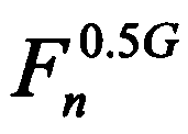 는 상기 n 번째 프레임이 0.5 GMII로 전달될 때 해당 프레임의 시간간격을 나타내고,
 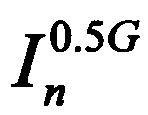 는 상기 해당 프레임이 가지는 IFG의 시간간격을 나타낸다. 이때 단위는 바이트 타임이다.
도 3 내지 도 5에서,
프레임의 길이는 바이트 단위로 볼 때 동일하지만, GMII는 125 MHz에서 동작하고 0.5 GMII는 62.5 MHz에서 동작하므로, 0.5 GMII에서의 프레임 시간은 GMII에서의 프레임 시간보다 2배의 길이를 가지게 된다. 즉, T(x)를 바이트 타임 x에 대한 절대적인 시간을 나타내는 함수로 정의할 때 하기의 [수학식 1]을 만족한다.
[규칙 제91조에 의한 정정 17.01.2012]
수학식 1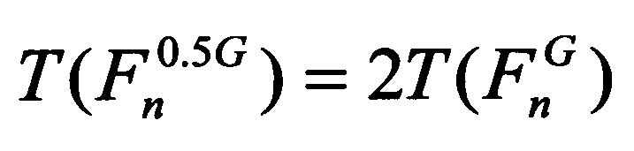
수학식 1
따라서, GMII에서는 IFG 구간이지만 0.5 GMII에서는 n 번째 프레임이 전송된다.
한편, n 번째 프레임에 이어서 따라오는 n+1 번째 프레임이 가지는 IFG의 길이에 따른 제어기(13)의 기능에 대해 살펴본다.
[규칙 제91조에 의한 정정 17.01.2012]
먼저, 도 3에 도시된 바와 같이 n+1 번째 프레임이 가지는 IFG의 길이가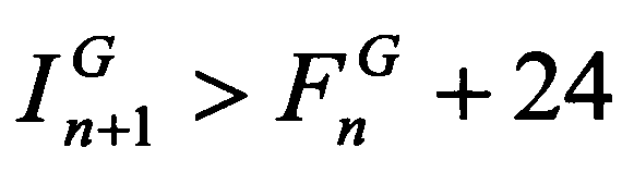 (여기서, 24는 클럭 수를 의미함)인 경우, 이는 500 Mbps 미만으로 프레임이 전달되는 경우로서 n+1 번째 프레임은 지연 없이 전달된다. 이때 제어기(13)는
 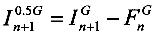 를 만족하도록 IFG의 길이(바이트 수)를
 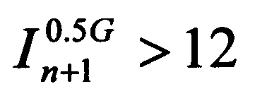 범위 내에서 줄여 링크 효율을 향상시킨다.
먼저, 도 3에 도시된 바와 같이 n+1 번째 프레임이 가지는 IFG의 길이가
[규칙 제91조에 의한 정정 17.01.2012]
다음으로, 도 4에 도시된 바와 같이 n+1 번째 프레임이 가지는 IFG의 길이가 인 경우, 이는 500 Mbps로 프레임이 전달되는 경우로서 n+1 번째 프레임의 TX_EN은 지연 없이 생성 가능하다. 즉, GMII의 n+1 번째 프레임의 전송 시작점과 0.5 GMII의 n+1 번째 프레임의 전송 시작점이 정확히 일치하기 때문에 n+1 번째 프레임을 지연 없이 곧바로 전송할 수 있다. 이때 제어기(13)는 IFG의 길이를 최소길이인
  로 설정한다.
다음으로, 도 4에 도시된 바와 같이 n+1 번째 프레임이 가지는 IFG의 길이가
[규칙 제91조에 의한 정정 17.01.2012]
다음으로, 도 5에 도시된 바와 같이 n+1 번째 프레임이 가지는 IFG의 길이가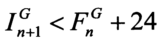 인 경우, 이는 500 Mbps를 초과하여 프레임이 전달되는 경우로서 n+1 번째 프레임은 버퍼링되어야 하고, TX_EN이 지연되어 발생한다. 이유는 0.5 GMII에서 n 번째 프레임을 다 전송하기 전에 GMII에서 n+1 번째 프레임이 발생하였기 때문이다. 이때, 제어기(13)는 IFG의 길이를 최소길이인
 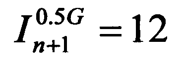 로 설정한다.
다음으로, 도 5에 도시된 바와 같이 n+1 번째 프레임이 가지는 IFG의 길이가
이와 같은 일이 지속적으로 발생한다는 것은 GMII에서 500 Mbps 이상으로 프레임을 입력하고 있다는 것을 의미한다. 만약 순간적으로 500 Mbps를 초과하더라도 평균적으로 500 Mbps로 유입될 경우 송신 버퍼(11)의 길이를 충분히 확보하면 프레임의 손실을 막을 수 있다. 그러나 지속적으로 프레임의 전송률이 500 Mbps를 초과한다면 다량의 프레임 손실이 발생하게 되므로 이를 막기 위한 방안이 필요하다.
이러한 프레임 손실을 예방하기 위해, 제어기(13)는 흐름 제어(FC : Flow Control)를 수행한다. 전술한 바와 같이 GMII를 통해 최소 IFG을 유지하면서 프레임들이 지속적으로 500 Mbps 이상의 속도로 유입되면 송신 버퍼(11)의 길이를 아무리 크게 잡아도 프레임 손실(loss)이 발생하게 된다. 따라서 제어기(13)는 송신 버퍼(11)의 길이가 어느 정도 이상 차오르면 프레임을 더 이상 전달하지 않도록 송신측으로 중지(pause) 프레임을 전송한다.
흐름 제어는 802.3x 규격의 일부이다. 이는 네트워크상에 'back-pressure'를 만드는 것으로, 포트에 트래픽 과부하가 걸리는 것을 줄여준다. 중지 프레임을 보낼 때 목적지 MAC 주소는 01-80-C2-00-00-01을 사용하도록 예약되어 있다. 또한 MAC 제어용 opcode는 0x0001이다. 전송 중단을 요청하는 기간은 비트 타임 단위로 0 ~ 65,535까지 설정할 수 있다.
이하, 도 6을 참조하여 S&S 부계층(30)의 구조에 대해 상세히 살펴보기로 한다.
도 6에 도시된 바와 같이, 본 발명에 따른 S&S 부계층(30)은 직렬화부(31), 및 병렬화부(32)를 포함한다.
먼저, 직렬화부(4D-to-2D Serializer)(31)는 4개의 심벌벡터(An, Bn, Cn, Dn)에서 (An, Bn)을 Pn으로, (Cn, Dn)을 Qn으로 직렬화한다.
병렬화부(32)는 PMA 수신부(42)로부터 입력되는 Pn, Qn을 각각 (An, Bn)과 (Cn, Dn)으로 복원하여야 한다. 따라서 심벌벡터의 동기를 찾는 것이 매우 중요하다. 즉, Pn에서 어떤 순간에 유입되는 심벌이 An인지 Bn인지 식별해야 한다. 마찬가지로 Qn에서 어떤 순간에 유입되는 심벌이 Cn인지 Bn인지 식별해야 한다.
이를 위해 병렬화부(32)는 제 1 병렬화기(321), 지연기(322), 제 2 병렬화기(323), 및 동기 검출기(324)를 포함한다.
제 1 병렬화기(2D-to-4D De-Serializer 1)(321)는 PMA 수신부(42)로부터 입력되는 2개의 심벌벡터를 4개의 심벌벡터로 병렬화한다.
지연기(322)는 PMA 수신부(42)로부터 입력되는 2개의 심벌벡터를 한 클럭 지연시킨다.
제 2 병렬화기(2D-to-4D De-Serializer 2)(323)는 지연기(322)에 의해 한 클럭 지연된 2개의 심벌벡터를 4개의 심벌벡터로 병렬화한다.
동기 검출기(2D-Sync. Detector)(324)는 IFG 구간에서 전달되는 Idle 심벌벡터를 이용하여 동기를 검출한다. 이때, 동기 검출기(324)는 프레임(데이터) 구간이 아니라, Idle 심벌벡터가 유입되는 IFG 구간에서 동기를 검출한다.
프레임 구간에서 각 심벌은 {+2, +1, 0, -1, -2}의 전압값 중에서 임의 값을 가지지만, Idle 심벌벡터는 {0, -2}의 전압 값만을 가진다.
따라서, Idle 심벌벡터는 전압이 변화하는 순서가 일정한 패턴을 가진다.
결국, 동기 검출기(324)는 IFG 구간에서 전달되는 Idle 심벌벡터의 전압 패턴을 기반으로 동기를 검출한다.
즉, 동기 검출기(324)는 제 1 병렬화기(321)로부터 출력되는 심벌들의 동기가 맞으면 제 1 병렬화기(321)로부터 출력되는 심벌을 PCS 수신부(22)로 전달하고, 제 1 병렬화기(321)로부터 출력되는 심벌들의 동기가 맞지 않으면 제 2 병렬화기(323)로부터 출력되는 심벌을 PCS 수신부(22)로 전달한다. 이때, 제 1 병렬화기(321)로부터 출력되는 심벌 및 제 2 병렬화기(323)로부터 출력되는 심벌 중에서 반드시 하나는 동기가 맞는다.
예를 들어, 제 1 병렬화기(321)로부터 출력되는 심벌의 시퀀스가 An, Bn, An+1, Bn+1, … 과 같다면(Idle 심벌벡터의 전압 패턴 만족) 동기가 정확히 맞는 상태이다. 이 경우 지연기(322)에 의해 한 클럭 지연된 심벌의 시퀀스는 Bn, An+1, Bn+1, An+2, …와 같다.
다른 예로, 제 1 병렬화기(321)로부터 출력되는 심벌의 시퀀스가 Bn, An+1, Bn+1, An+2, …과 같다면(Idle 심벌벡터의 전압 패턴 불만족) 동기가 맞지 않는 상태이다. 이때, 지연기(322)에 의해 한 클럭 지연된 심벌의 시퀀스는 An+1, Bn+1, An+2, Bn+2…와 같다. 따라서, 동기 검출기(324)는 제 2 병렬화기(323)로부터 출력되는 심벌이 동기가 맞으므로, 제 2 병렬화기(323)로부터 출력되는 심벌을 PCS 수신부(22)로 전달한다.
마찬가지로, Qn 시퀀스도 동일한 과정을 겪게 된다.
아울러, 동기 검출기(324)는 초기화 과정(startup sequence)에서도 Idle 심벌벡터(Idle 신호)를 이용하여 동기를 검출하여 초기 동기화 과정을 수행한다.
도 7 은 본 발명에 따른 초기화 과정에 대한 일예시도이다.
먼저, 전원이 켜지면 일반적인 자동절충(Auto-negotiation) 과정을 수행한다.
이후, 마스터가 Mode_1으로 동작하여 Idle 신호를 송신하고, 슬레이브는 Mode_Z를 유지한다. 이 과정에서 마스터는 반향 제거기와 누화 제거기의 동작을 수렴시키고, 슬레이브는 필터와 등화기의 동작을 안정화시킨다. 이는 1000BASE-T의 초기화 과정과 동일하다.
이때, 슬레이브는 마스터로부터의 Idle 신호를 이용하여 동기화 과정을 수행한다.
이후, 마스터와 슬레이브의 역할이 반대가 된다. 이때 마스터는 슬레이브로부터의 Idle 신호를 이용하여 동기화 과정을 수행한다.
이후, 마스터와 슬레이브는 Mode_1으로 동작하여 타이밍과 위상동기를 획득하는 과정을 수행한다.
이렇게 초기화 과정이 완료되면 정상동작 모드인 Mode_N으로 돌입한다.
이상에서 설명한 본 발명은, 본 발명이 속하는 기술 분야에서 통상의 지식을 가진 자에게 있어 본 발명의 기술적 사상을 벗어나지 않는 범위 내에서 여러 가지 치환, 변형 및 변경이 가능하므로 전술한 실시예 및 첨부된 도면에 의해 한정되는 것이 아니다.
본 발명은 2P UTP 케이블을 통해 500 메가급 서비스를 제공하는 시스템에 적용 가능하다.
Claims (9)
- GMII(Gigabit Media Independent Interface)로부터 입력되는 송신 데이터를 0.5 GMII에 부합하도록 속도를 정합시키는 속도 정합수단;상기 속도 정합수단에 의해 속도가 정합된 송신 데이터를 이용하여 4개의 심벌벡터를 생성하고, 심벌벡터 처리수단에 의해 병렬화된 4개의 심벌벡터를 이용하여 수신 데이터를 생성하는 데이터 변환수단;상기 데이터 변환수단에 의해 생성된 4 개의 심벌벡터를 2개의 심벌벡터로 직렬화하고, 통신수단으로부터 전달받은 2개의 심벌벡터를 4개의 심벌벡터로 병렬화하는 상기 심벌벡터 처리수단; 및상기 심벌벡터 처리수단에 의해 직렬화된 2개의 심벌벡터를 하이브리드 회로로 전달하고, 상기 하이브리도 회로로부터 전달받은 2개의 심벌벡터를 상기 심벌벡터 처리수단으로 전달하는 상기 통신수단을 포함하는 2P 선로를 이용한 500 Mbps 전송 장치.
- 제 1 항에 있어서,상기 속도 정합수단은,상기 GMII로부터 입력되는 송신 데이터를 저장하는 송신 버퍼;상기 데이터 변환수단이 생성한 수신 데이터를 저장하는 수신 버퍼; 및상기 송신 버퍼 및 상기 수신 버퍼를 이용하여 상기 GMII과 상기 0.5 GMII 사이의 속도를 정합하는 제어기를 포함하는 2P 선로를 이용한 500 Mbps 전송 장치.
- 제 2 항에 있어서,상기 제어기는,1 Gbps를 500 Mbps로 줄이기 위해 상기 송신 버퍼에 저장되는 속도는 125 MHz 클럭을 사용하고, 상기 송신 버퍼에서 송신 데이터를 송출하는 속도는 62.5 MHz 클럭을 사용하는 것을 특징으로 하는 2P 선로를 이용한 500 Mbps 전송 장치.
- 제 2 항에 있어서,상기 제어기는,상기 GMII와 상기 0.5 GMII 사이에 송신 데이터(이더넷 프레임) 매핑 시 IFG(Inter Frame Group)의 길이를 조절하는 것을 특징으로 하는 2P 선로를 이용한 500 Mbps 전송 장치.
- 제 4 항에 있어서,상기 제어기는,상기 송신 버퍼의 여유 공간이 임계치를 초과하면 데이터 송신의 중지를 요청하는 중지(pause) 프레임을 송신측으로 전송하는 것을 특징으로 하는 2P 선로를 이용한 500 Mbps 전송 장치.
- 제 1 항에 있어서,상기 심벌벡터 처리수단은,상기 데이터 변환수단에 의해 생성된 4 개의 심벌벡터를 2개의 심벌벡터로 직렬화하는 직렬화수단; 및상기 통신수단으로부터 전달받은 2개의 심벌벡터를 4개의 심벌벡터로 병렬화하는 병렬화수단을 포함하는 2P 선로를 이용한 500 Mbps 전송 장치.
- 제 6 항에 있어서,상기 병렬화수단은,상기 통신수단으로부터 입력되는 2개의 심벌벡터를 4개의 심벌벡터로 병렬화하는 제 1 병렬화기;상기 통신수단으로부터 입력되는 2개의 심벌벡터를 한 클럭 지연시켜 저장하는 동기 버퍼;상기 동기 버퍼에 저장되어 있는 한 클럭 지연된 2개의 심벌벡터를 4개의 심벌벡터로 병렬화하는 제 2 병렬화기; 및IFG 구간에서 Idle 심벌벡터를 이용하여 동기를 검출하는 동기 검출기를 포함하는 2P 선로를 이용한 500 Mbps 전송 장치.
- 제 7 항에 있어서,상기 동기 검출기는,상기 Idle 심벌벡터의 전압 패턴을 기반으로 동기를 검출하는 것을 특징으로 하는 2P 선로를 이용한 500 Mbps 전송 장치.
- 제 7 항에 있어서,상기 동기 검출기는,상기 제 1 병렬화기로부터 출력되는 심벌의 동기가 맞지 않으면 상기 제 2 병렬화기로부터 출력되는 심벌을 상기 데이터 변환수단으로 전달하고, 상기 제 2 병렬화기로부터 출력되는 심벌의 동기가 맞지 않으면 상기 제 1 병렬화기로부터 출력되는 심벌을 상기 데이터 변환수단으로 전달하는 것을 특징으로 하는 2P 선로를 이용한 500 Mbps 전송 장치.
Priority Applications (1)
| Application Number | Priority Date | Filing Date | Title |
|---|---|---|---|
| US13/997,510 US9042464B2 (en) | 2010-12-24 | 2011-11-23 | 500 Mbps transmission apparatus using 2P line |
Applications Claiming Priority (2)
| Application Number | Priority Date | Filing Date | Title |
|---|---|---|---|
| KR10-2010-0134505 | 2010-12-24 | ||
| KR1020100134505A KR101244009B1 (ko) | 2010-12-24 | 2010-12-24 | 2P 선로를 이용한 500Mbps 전송 장치 |
Publications (1)
| Publication Number | Publication Date |
|---|---|
| WO2012086933A1 true WO2012086933A1 (ko) | 2012-06-28 |
Family
ID=46314161
Family Applications (1)
| Application Number | Title | Priority Date | Filing Date |
|---|---|---|---|
| PCT/KR2011/008971 Ceased WO2012086933A1 (ko) | 2010-12-24 | 2011-11-23 | 2P 선로를 이용한 500Mbps 전송 장치 |
Country Status (3)
| Country | Link |
|---|---|
| US (1) | US9042464B2 (ko) |
| KR (1) | KR101244009B1 (ko) |
| WO (1) | WO2012086933A1 (ko) |
Families Citing this family (2)
| Publication number | Priority date | Publication date | Assignee | Title |
|---|---|---|---|---|
| WO2020166859A1 (en) * | 2019-02-11 | 2020-08-20 | Lg Electronics Inc. | Method and apparatus for transmitting buffer status report by iab node in wireless communication system |
| US12120034B2 (en) | 2020-10-19 | 2024-10-15 | B&R Industrial Automation GmbH | Data flow control in a network |
Citations (4)
| Publication number | Priority date | Publication date | Assignee | Title |
|---|---|---|---|---|
| KR20010047753A (ko) * | 1999-11-23 | 2001-06-15 | 오길록 | 무선 랜의 고속 억세스 포인트 장치 및 그 운용 방법 |
| US20040246953A1 (en) * | 2003-06-05 | 2004-12-09 | Broadcom Corporation | System for interfacing media access control module to small form factor pluggable module |
| US20070058680A1 (en) * | 2005-07-26 | 2007-03-15 | Dong-Joon Choi | Apparatus and method for multimedia data transmission and reception in cable network using broadband and physical layer frame structure |
| KR20100037739A (ko) * | 2008-10-02 | 2010-04-12 | 한국전자통신연구원 | 기가 비트 수동형 광 가입장망의 가입자 종단장치와 그 장치에서의 상향 프레임 처리 방법 |
Family Cites Families (1)
| Publication number | Priority date | Publication date | Assignee | Title |
|---|---|---|---|---|
| US8089984B2 (en) * | 2009-06-23 | 2012-01-03 | Broadcom Corporation | Method and system for network communications via a configurable multi-use ethernet PHY |
-
2010
- 2010-12-24 KR KR1020100134505A patent/KR101244009B1/ko active Active
-
2011
- 2011-11-23 WO PCT/KR2011/008971 patent/WO2012086933A1/ko not_active Ceased
- 2011-11-23 US US13/997,510 patent/US9042464B2/en active Active
Patent Citations (4)
| Publication number | Priority date | Publication date | Assignee | Title |
|---|---|---|---|---|
| KR20010047753A (ko) * | 1999-11-23 | 2001-06-15 | 오길록 | 무선 랜의 고속 억세스 포인트 장치 및 그 운용 방법 |
| US20040246953A1 (en) * | 2003-06-05 | 2004-12-09 | Broadcom Corporation | System for interfacing media access control module to small form factor pluggable module |
| US20070058680A1 (en) * | 2005-07-26 | 2007-03-15 | Dong-Joon Choi | Apparatus and method for multimedia data transmission and reception in cable network using broadband and physical layer frame structure |
| KR20100037739A (ko) * | 2008-10-02 | 2010-04-12 | 한국전자통신연구원 | 기가 비트 수동형 광 가입장망의 가입자 종단장치와 그 장치에서의 상향 프레임 처리 방법 |
Also Published As
| Publication number | Publication date |
|---|---|
| US9042464B2 (en) | 2015-05-26 |
| KR20120072651A (ko) | 2012-07-04 |
| KR101244009B1 (ko) | 2013-03-14 |
| US20130287128A1 (en) | 2013-10-31 |
Similar Documents
| Publication | Publication Date | Title |
|---|---|---|
| CA2450825C (en) | Protocol independent transmission using a 10 gigabit attachment unit interface | |
| EP1903733B1 (en) | Method and system for an extended range ethernet line code | |
| US5406559A (en) | Isochronous link protocol | |
| US8179910B2 (en) | Method and system for an asymmetric PHY operation for ethernet A/V bridging and ethernet A/V bridging extensions | |
| US6574242B1 (en) | Method for the transmission and control of audio, video, and computer data over a single network fabric | |
| US5574722A (en) | Protocol independent switch | |
| US20040125809A1 (en) | Ethernet interface over ATM Cell, UTOPIA xDSL in single and multiple channels converter/bridge on a single chip and method of operation | |
| US9143464B2 (en) | Method and system for speed negotiation for twisted pair links using intelligent E-FIFO in fibre channel systems | |
| CN102164062A (zh) | 以太网通信系统、多速率以太网设备及其方法 | |
| WO2012086933A1 (ko) | 2P 선로를 이용한 500Mbps 전송 장치 | |
| KR100415580B1 (ko) | 다양한 홈 네트워킹 인터페이스를 갖는 댁내 망과 액세스망을 연결하는 홈 게이트웨이 장치 | |
| WO2011152818A1 (en) | Multiplexed serial media independent interface | |
| WO2015046701A1 (ko) | 엑세스 네트워크에서의 홈 네트워크 신호 중계 장치 및 이를 이용한 엑세스 네트워크에서의 홈 네트워크 신호 중계 방법 | |
| US8190766B2 (en) | Across-device communication protocol | |
| KR20130116477A (ko) | 이더넷 l2 스위치 장치 및 그 데이터 전송 방법 | |
| WO2020138704A1 (ko) | 실시간 보상 수단을 구비한 분산 제어 장치 | |
| Moorthy | Gigabit ethernet | |
| KR100364744B1 (ko) | 동기전송모듈(stm) 링크 포트 이중화 장치 | |
| US20050078960A1 (en) | Subscriber distribution network apparatus and subscriber line unit that facilitates connection to network switch | |
| WO2015152569A1 (ko) | G.hn 기술이 적용된 액세스 네트워크의 동기화 통신 방법과 이를 이용하는 액세스 네트워크 집선장비, 액세스 네트워크 단말, 및 액세스 네트워크 시스템 | |
| KR20070033558A (ko) | 이종 인터페이스 네트워크 시스템들 간의 데이터 전송 방법및 장치 | |
| CN101222409A (zh) | 点到点链路和共享链路的桥接系统及方法 | |
| KR20080086738A (ko) | 멀티탭 및 멀티탭 제공 방법 | |
| WO2018012819A1 (ko) | 번들 케이블 내 이종 기술간 공존 간섭을 회피하는 방법 및 장치 | |
| HK1119504B (en) | Method and system for wire communication |
Legal Events
| Date | Code | Title | Description |
|---|---|---|---|
| 121 | Ep: the epo has been informed by wipo that ep was designated in this application |
Ref document number: 11851324 Country of ref document: EP Kind code of ref document: A1 |
|
| NENP | Non-entry into the national phase |
Ref country code: DE |
|
| WWE | Wipo information: entry into national phase |
Ref document number: 13997510 Country of ref document: US |
|
| 122 | Ep: pct application non-entry in european phase |
Ref document number: 11851324 Country of ref document: EP Kind code of ref document: A1 |