WO2012086619A1 - 眼鏡型無線通信機 - Google Patents
眼鏡型無線通信機 Download PDFInfo
- Publication number
- WO2012086619A1 WO2012086619A1 PCT/JP2011/079437 JP2011079437W WO2012086619A1 WO 2012086619 A1 WO2012086619 A1 WO 2012086619A1 JP 2011079437 W JP2011079437 W JP 2011079437W WO 2012086619 A1 WO2012086619 A1 WO 2012086619A1
- Authority
- WO
- WIPO (PCT)
- Prior art keywords
- antenna element
- antenna
- wireless communication
- communication device
- type wireless
- Prior art date
- Legal status (The legal status is an assumption and is not a legal conclusion. Google has not performed a legal analysis and makes no representation as to the accuracy of the status listed.)
- Ceased
Links
Images




Classifications
-
- H—ELECTRICITY
- H01—ELECTRIC ELEMENTS
- H01Q—ANTENNAS, i.e. RADIO AERIALS
- H01Q1/00—Details of, or arrangements associated with, antennas
- H01Q1/27—Adaptation for use in or on movable bodies
- H01Q1/273—Adaptation for carrying or wearing by persons or animals
-
- G—PHYSICS
- G02—OPTICS
- G02C—SPECTACLES; SUNGLASSES OR GOGGLES INSOFAR AS THEY HAVE THE SAME FEATURES AS SPECTACLES; CONTACT LENSES
- G02C11/00—Non-optical adjuncts; Attachment thereof
- G02C11/10—Electronic devices other than hearing aids
-
- H—ELECTRICITY
- H01—ELECTRIC ELEMENTS
- H01Q—ANTENNAS, i.e. RADIO AERIALS
- H01Q9/00—Electrically-short antennas having dimensions not more than twice the operating wavelength and consisting of conductive active radiating elements
- H01Q9/04—Resonant antennas
- H01Q9/16—Resonant antennas with feed intermediate between the extremities of the antenna, e.g. centre-fed dipole
- H01Q9/26—Resonant antennas with feed intermediate between the extremities of the antenna, e.g. centre-fed dipole with folded element or elements, the folded parts being spaced apart a small fraction of operating wavelength
-
- H—ELECTRICITY
- H01—ELECTRIC ELEMENTS
- H01Q—ANTENNAS, i.e. RADIO AERIALS
- H01Q9/00—Electrically-short antennas having dimensions not more than twice the operating wavelength and consisting of conductive active radiating elements
- H01Q9/04—Resonant antennas
- H01Q9/30—Resonant antennas with feed to end of elongated active element, e.g. unipole
- H01Q9/42—Resonant antennas with feed to end of elongated active element, e.g. unipole with folded element, the folded parts being spaced apart a small fraction of the operating wavelength
-
- H—ELECTRICITY
- H04—ELECTRIC COMMUNICATION TECHNIQUE
- H04B—TRANSMISSION
- H04B1/00—Details of transmission systems, not covered by a single one of groups H04B3/00 - H04B13/00; Details of transmission systems not characterised by the medium used for transmission
- H04B1/38—Transceivers, i.e. devices in which transmitter and receiver form a structural unit and in which at least one part is used for functions of transmitting and receiving
- H04B1/3827—Portable transceivers
- H04B1/385—Transceivers carried on the body, e.g. in helmets
Definitions
- the present invention relates to a glasses-type wireless communication device.
- electronic devices having the appearance of glasses such as 3D glasses for viewing 3D television, 3D glasses for enjoying 3D games, and eyeglass-type head-mounted displays, have been developed.
- These electronic devices may include an antenna and perform wireless communication.
- Patent Document 1 describes a technique for arranging an antenna in the vicinity of a substantially central portion of a lens frame.
- Patent Document 2 describes that an antenna is incorporated in the temple portion.
- Japanese Patent Publication “JP 2007-174612 A” (published July 5, 2007) Japanese public utility model publication "Japanese Utility Model Publication No. 62-193220 (published December 8, 1987)"
- the antenna characteristics may be deteriorated.
- FIG. 9 and FIG. 10 are schematic diagrams showing an example of a schematic radiation direction (beam direction) of an antenna beam in a spectacle-type wireless communication device according to the prior art.
- the antenna element 90 of the antenna is in the vicinity of the user's nose, as shown in FIG.
- the range of the beam direction that the antenna element 90 can transmit and receive is affected by the user's head, and the antenna element 90 The space in the front direction of the user's face (a space about half of all directions).
- the antenna element 90 of the antenna is in the vicinity of the user's ear as shown in FIG.
- the antenna element 90 is on the side face of the user's face, as shown in FIG. 10B, the range of the beam direction in which the antenna element 90 can be transmitted and received is affected by the user's head, and the antenna element 90 A space in the direction of the side of the user's face (a space about half of all directions).
- the beam direction of the antenna is the front direction or the side direction of the face, there is a problem that the transmission / reception characteristics deteriorate depending on the arrival direction of the radio wave. Further, since the antenna is close to the head, there is a problem that the antenna gain is reduced.
- the present invention has been made in view of the above problems, and a main object thereof is to realize a glasses-type wireless communication apparatus having a good antenna gain.
- a glasses-type wireless communication device includes a glasses-type wireless communication device including left and right eyepieces, pads, wisdom, temples, and an antenna element for performing wireless communication.
- the antenna element is disposed in a region along the outer peripheral portion of the eyepiece portion, including the wisdom and not including a connection portion with the pad. .
- the antenna element is closest to the head in glasses.
- the antenna element can be arranged at a position where the shadowing due to the influence of the user's head can be reduced by avoiding the part (for example, pad and temple) and away from the head, thereby improving the antenna gain. Play.
- the eyeglass-type wireless communication device According to the eyeglass-type wireless communication device according to the present invention, shadowing due to the influence of the user's head is reduced, and deterioration of transmission / reception performance due to the arrival direction of radio waves is eliminated. Further, since the antenna element is located at a location away from the head, the antenna gain is improved.
- FIG. 2 is a diagram illustrating an example of an internal configuration of a glasses-type wireless communication device according to Embodiment 1.
- FIG. It is a general-view figure of a spectacles type radio communication equipment. It is a figure which shows an example of the beam direction of the antenna of the spectacles type radio
- FIG. It is a figure which shows an example of the beam direction of the antenna of the spectacles type radio
- FIG. (A) shows an example of a spectacles type radio
- (b) shows an example of the beam direction of the antenna element of (a).
- (A) shows an example of an eyeglass-type wireless communication device when the antenna element is arranged on the side surface
- (b) shows an example of the beam direction of the antenna element of (a). It is a figure which shows arrangement
- the eyeglass-type wireless communication device is not particularly limited as long as it has the appearance of glasses and performs wireless communication.
- 3D glasses, a head-mounted display, a headset, a radio receiver, a personal identification device, and the like It can be applied to various uses.
- Embodiment 1 Hereinafter, it will be as follows if one Embodiment (Embodiment 1) of this invention is described with reference to FIGS.
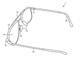
- FIG. 2 is an overview of the glasses-type wireless communication device 1 according to this embodiment.
- the glasses-type wireless communication device 1 has the appearance of glasses, and includes an eyepiece unit 11, a rim 12, a bridge 13, a temple 14, a modern 15, a wisdom 16, a hinge 17, a pad 18, And Klings 19 and the like.
- the eyepiece 11 is an optical member disposed in front of the left and right eyes, and may be, for example, a spectacle-type lens, and may be a display for displaying an image such as an LCD (Liquid Crystal Display) or a retina operation display. It may be incorporated.
- a spectacle-type lens may be, for example, a display for displaying an image such as an LCD (Liquid Crystal Display) or a retina operation display. It may be incorporated.
- the rim 12 is a holding member that surrounds the eyepiece 11 and holds the eyepiece 11.
- the rim 12 does not necessarily need to protect the entire area around the eyepiece 11, and may protect approximately half or only a part of the eyepiece 11.
- the glasses-type wireless communication device 1 may not include the rim 12.
- the bridge 13 is a connecting member for connecting the left and right eyepieces 11.
- the bridge 13 connects the left and right eyepieces 11 in a predetermined positional relationship with or without the rim 12 interposed therebetween.
- the temple 14 is a member including an ear hook and is also called a vine.
- a portion in contact with the user's ear may be covered with a covering member called a modern 15.
- the wi 16 is a connection member for connecting the eyepiece 11 and the temple 14.
- the wisdom 16 is provided in a region along the outer periphery of the eyepiece 11 and may be integrated with the rim 12 or may be independently coupled to the eyepiece.
- the hinge 17 is an opening / closing member for making the temple 14 foldable with respect to the eyepiece 11 or the like, and is provided between the wisdom 16 and the temple 14.
- the pad 18 is a member that contacts the user's nose.
- the clings 19 is a connecting member that connects the pad 18 and the eyepiece 11.
- the krings 19 connects the pad 18 and the eyepiece 11 in a predetermined positional relationship with or without the rim 12 interposed therebetween.
- the glasses-type wireless communication device 1 may not include the krings 19, and in this case, the pad 18 and the eyepiece 11 or the rim 12 can be directly coupled.
- each part may be comprised with the same material as general spectacles, for example, it is not limited to this.
- metal for example, titanium, titanium alloy, aluminum alloy, magnesium alloy, nickel chrome alloy, and stainless steel
- plastic for example, epoxy resin
- Celluloid, acetate, polyamide, etc. can be used, but is not limited thereto.
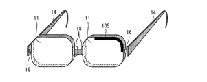
- FIG. 1 is a diagram illustrating an internal configuration of the glasses-type wireless communication device 1.
- limb 12 is demonstrated in FIG. 1, this embodiment is not limited to this, The structure containing the rim
- the rim 12 is preferably formed of an insulator such as plastic. Thereby, antenna characteristics can be further improved.
- the glasses-type wireless communication device 1 has an antenna 100.
- the antenna 100 includes a power supply unit 101 that supplies power to the antenna 100, a control unit 102 that controls an electric signal, a wireless unit 103 that transmits and receives data via the antenna element 105, and power from the power supply unit 101 to the antenna element 105.
- This is a dipole antenna including a feeding line 104 to be supplied and an antenna element 105.
- the power supply unit 101, the control unit 102, and the wireless unit 103 are arranged in the temple 14.
- the feed line 104 is connected to the antenna element 105 through the temple 14 through the wisdom 16.
- the antenna element 105 is arranged along the outer periphery of the eyepiece 11 around the wisdom 16.
- the antenna element 105 includes an antenna element (first antenna element) 105a extending from the wisdom 16 to the vertical upper side of the eyepiece unit 11, and an antenna element (second antenna) extending from the wisdom 16 to the vertical lower side of the eyepiece part 11.
- Element) 105b that is, the antenna elements 105a and 105b are arranged so as to sandwich the wisdom 16 in pairs.
- the outer periphery of the eyepiece part 11 refers to the outer periphery in the surface facing the user's eyes.
- the antenna element 105 is disposed on the side end face of the eyepiece 11 as shown in FIG. 1, but the present invention is not limited to this.
- the antenna element 105 may be provided on a surface (lens surface) facing the user's eye in the eyepiece unit 11.
- the antenna element 105 may be provided between the eyepiece part 11 and the rim 12, or provided inside or outside the rim 12. Also good.
- the antenna element 105 should just be arrange
- the antenna element 105 is formed between the eyepiece 11 and the rim 12 or in the rim 12, the antenna element 105 is not exposed to the outside.
- the aesthetics and durability of the communication device 1 can be improved. Further, it is possible to suitably prevent the appearance of the glasses from collapsing such as the antenna element 105 protruding.
- the antenna elements 105a and 105b have an L shape with rounded corners as shown in FIG.
- the antenna element 105a and the antenna element 105b may be different from each other in shape and / or length. By configuring the antenna element in this way, the resonance frequencies of the two antennas can be made different, so that it is possible to correspond to a plurality of frequency bands.
- the antenna element 105 is disposed along the outer periphery of the left eyepiece 11 of the glasses-type wireless communication device 1, but the antenna element 105 extends along the outer periphery of the right eyepiece 11. It may be arranged as follows. Further, the antenna element 105 is not disposed at a connection portion with the pad 18 that contacts the face (connection portion with the crings 19). That is, the antenna element 105 is disposed along the outer periphery of at least one of the left and right eyepieces 11 excluding the connection part with the pad 18.
- the antenna elements 105a and 105b are each disposed in a region along the outer periphery of the eyepiece portion 11, including the wisdom 16 and not including the connection portion with the pad 18. 16 extend in different directions along the outer periphery of the eyepiece 11.
- the antenna elements 105a and 105b are arranged. Can be arranged at a location far from the user's head and where shadowing due to the influence of the user's head can be reduced, as will be described later.
- more than half of the antenna element 105 is arranged on the side of the eye 16 of the glasses-type wireless communication device 1. More specifically, a portion that occupies more than half the volume of the antenna element 105 is disposed at a position closer to the edge 16 where the feeder line 104 is provided than the pad 18. In the eyeglass-type wireless communication device 1 shown in FIG. 1, about four fifths of the antenna element 105 is arranged on the side of the wisdom 16.
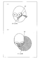
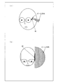
- FIG. 3 shows the range of the beam direction when the glasses-type wireless communication device 1 of FIG. 1 is used.
- FIG. 3A is a diagram illustrating an example when the user's face is viewed obliquely when the glasses-type wireless communication device 1 is used, and FIG. 3B is an antenna when the user is viewed from directly above. A diagram of the beam direction of the element 105 is shown.
- the antenna element 105 of the glasses-type wireless communication device 1 is arranged in a region including the wisdom 16 and not including the connection portion with the pad 18. That is, the antenna element 105 is disposed in the outward extension when the user's head is viewed from above, and the approximate beam direction of the antenna element 105 is as shown in FIG. Centering on 105, it extends in the direction of the front face and the side face and direction of the user's face.
- shadowing due to the influence of the user's head is reduced as compared with the glasses-type wireless communication device according to the related art as shown in FIGS. 9 and 10.
- the open space of the antenna is widened. Thereby, the restriction on the beam direction of the antenna is relaxed, and the deterioration of the transmission / reception performance due to the arrival direction of the radio wave is eliminated.
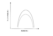
- FIG. 5 is a graph showing the antenna gain with respect to frequency.
- the antenna gain of the antenna 100 is indicated by a solid line, and the antenna gain of the antenna 90 arranged as shown in FIG. 9 is indicated by a dotted line.
- the horizontal axis represents frequency (MHz), and the vertical axis represents antenna gain (dBi).
- the antenna gain of the antenna 100 is higher than the antenna gain of the antenna 90.
- the antenna element 105 is arranged in a region including the wisdom 16 and not including the connection portion with the pad 18, so that the antenna element 105 is located away from the head. This is because the influence of the portion as GND is reduced and the antenna gain is improved.
- the antenna element 105 is not provided in a place that directly contacts the user, such as the pad 18 and the temple 14. Thereby, an antenna gain can be improved suitably.
- the antenna 100 (antenna elements 105a and 105b) constitutes a dipole antenna.
- the antenna 100 works as a dipole antenna, so that the influence of the GND shape (the shape of the glasses-type wireless communication device 1) can be reduced. Further, since the antenna 100 functions as a dipole antenna, the beam direction of the antenna 100 can be easily controlled, and the beam in the front direction of the user's face can be narrowed down. Thereby, the antenna characteristics of the antenna 100 can be further improved.
- the antenna element 105a and the antenna element 105b may constitute a diversity antenna. As described above, when the antenna element 105a and the antenna element 105b constitute a diversity antenna such as MIMO, transmission / reception characteristics can be further improved.
- the antenna element 105 is composed of two antenna elements (antenna elements 105a and 105b).
- the present invention is not limited to this, and may be used as, for example, a monopole antenna.
- the antenna element 105 may be one of an element provided above the wisdom 16 (antenna element 105a) and an element provided below the wisdom 16 (antenna element 105b). Even in this case, as described above, the antenna element 105 is arranged at a position where shadowing due to the influence of the user's head can be reduced, and thus good antenna characteristics can be obtained.
- an additional antenna element may be provided.
- the length of the antenna element 105 (the antenna elements 105a and 105b) is not limited to that shown in FIG. 1 and is arranged in a region along the outer periphery of the eyepiece portion 11 excluding the connection portion with the pad 18.
- the length can be appropriately set according to the frequency band in which wireless communication is performed.
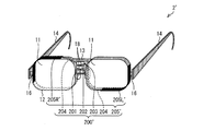
- FIG. 4 is a diagram showing a schematic configuration of a glasses-type radio communication device 1 ′ having a higher frequency band than the glasses-type radio communication device 1 shown in FIG.
- the length of the antenna element 105 'of the antenna 100' is shorter than the length of the antenna element 105 of FIG. All such antenna elements 105 ′ are disposed on the side of the wisdom 16 (the entire antenna elements 105 a and 105 b are disposed closer to the wisdom 16 than the pad 18).
- Such a spectacle-type radio communication device 1 ′ also has a beam direction range as shown in FIG. 3 as in the spectacle-type radio communication device 1, and the degradation of transmission / reception performance due to the arrival direction of radio waves is eliminated. Further, since the antenna element 105 ′ is located away from the user's head, the antenna gain is improved.
- the spectacles-type wireless communication device 1 having the antenna 100 in which the antenna element 105 is arranged at the upper part and the lower part of the eyepiece 11 around the wisdom 16 has been described. It is not limited.
- the eyeglass-type wireless communication device 1 may have an antenna in which an antenna element is arranged at the upper part and / or the lower part of the eyepiece 11 around the bridge 13.
- the spectacle-type wireless communication device 2 in which the antenna element 205 is arranged on the upper and / or lower portions of the left and right eyepieces 11 around the bridge 13 will be described.
- members such as the eyepiece 11, the rim 12, the bridge 13, the temple 14, the modern 15, the wisdom 16, the hinge 17, the pad 18, and the crings 19 have the same configuration as that of the first embodiment. .
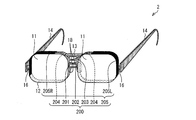
- FIG. 6 is a diagram illustrating an internal configuration of the glasses-type wireless communication device 2. 6 illustrates a configuration in which the glasses-type wireless communication device 2 includes the rim 12. However, the glasses-type wireless communication device 2 according to the present embodiment may have a configuration that does not include the rim 12. In the present embodiment, the rim 12 may be made of metal.
- the eyeglass-type wireless communication device 2 has an antenna 200.
- the antenna 200 includes a power supply unit 201, a control unit 202, a wireless unit 203, a feed line 204, and an antenna element 205. Note that each part of the antenna 200 performs the same processing as each part of the antenna 100.
- the antenna 200 is composed of two monopole antennas using metal parts such as the rim 12 and the bridge 13 as ground elements (GND).
- the power supply unit 201, the control unit 202, and the wireless unit 203 are disposed between the eyepiece units 11 (bridge 13).
- the feed line 204 is connected to the antenna element 205 through the rim 12 from the bridge 13 positioned between the left and right eyepieces 11.
- the antenna element 205 is disposed on each of the vertical upper sides of the left and right eyepieces 11 around the bridge 13.
- the antenna element 105 includes an antenna element (third antenna element) 205L disposed along the outer periphery of the left eyepiece 11 and an antenna element (third antenna element) disposed along the outer periphery of the right eyepiece 11 ( (Fourth antenna element) 205R.
- the antenna element 205 ⁇ / b> L is disposed on the left eyepiece 11
- the antenna element 205 ⁇ / b> R is disposed on the right eyepiece 11. That is, the antenna element 205 is arranged along the outer periphery of each of the left and right eyepieces 11 around the vertical upper side with the bridge 13 as the center.
- the antenna element 205 is arranged in a region including the wisdom 16 and not including the connection portion with the pad 18. In particular, it is preferable that a portion occupying half or more of the volume of the antenna element 205 is disposed at a position closer to the edge 16 than the pad 18. As shown in FIG. 6, the antenna element 205 (antenna elements 205L and 205R) is provided in a region including the wisdom 16, and approximately four fifths are disposed on the wisdom 16 side.
- the fact that more than half of the antenna element 205 is arranged on the side of the side 16 means that the part that occupies more than half of the volume of the antenna element 205L is arranged with the antenna element 205L rather than the pad 18.
- the antenna element 205R is disposed at a position nearer to the side 16 of the left eyepiece 11 and the antenna element 205R is disposed more than half of the antenna element 205R than the pad 18. It is arranged at a position close to the direction of the wisdom 16 provided on the side of the right eyepiece 11.
- FIG. 7 shows a schematic range of the beam direction when the glasses-type wireless communication device 2 of FIG. 6 is used.
- FIG. 7A is a diagram illustrating an example when the user's face is viewed obliquely when the glasses-type wireless communication device 2 is used, and FIG. 7B is an antenna when the user is viewed from directly above.
- a diagram of the beam direction of the element 205 is shown.
- the antenna element 205 of the glasses-type wireless communication device 2 is provided on each side of the glasses-type wireless communication device 2, includes the wisdom 16, and includes a connection portion with the pad 18. Is located in no area. That is, the antenna element 205 is disposed on both sides of the extended portion when the user's head is viewed from above, and the beam direction of the antenna element 205 at this time is as shown in FIG. Furthermore, it extends in almost all directions around the user's face, centering on the left and right antenna elements.
- the glasses-type wireless communication device 2 As described above, in the glasses-type wireless communication device 2 according to the present embodiment, the glasses-type wireless communication device according to the related art as shown in FIGS. 9 and 10 and the glasses-type wireless communication device 1 according to the first embodiment.
- shadowing due to the influence of the user's head is reduced, and the open space of the antenna is widened.
- limiting of the beam direction of an antenna is eased more, and the deterioration of the transmission / reception performance by the arrival direction of an electromagnetic wave is eliminated suitably.
- the strength of the radio transmitted and received by the antenna element 205 can be increased.
- the antenna element 205 is located away from the head by being arranged in a region including the wisdom 16 and not including the connection portion with the pad 18. Therefore, the influence of the user's head as GND is reduced, and the antenna gain is improved.
- the antenna element 205 is not provided in a place that directly contacts the user, such as the pad 18 and the temple 14. Thereby, an antenna gain can be improved suitably.
- the antenna element 205R and the antenna element 205L may constitute a diversity antenna. As described above, when the antenna element 205R and the antenna element 205L constitute a diversity antenna such as MIMO, the transmission / reception characteristics can be further improved.
- the antenna element 205R and the antenna element 205L are depicted as having the same shape, but the present invention is not limited to this, and the antenna element 205R and the antenna element 205L may be at least one of shape and length. By configuring so that the two antennas are different from each other, the resonance frequencies of the two antennas may be made different to correspond to a plurality of frequency bands.
- the antenna element 205 is configured by two antenna elements (antenna elements 205R and 205L) has been described.
- the present invention is not limited to this.
- the element 205 may be either one provided in the right eyepiece (antenna elements 205R, 205R ′) or one provided in the left eyepiece (antenna elements 205L, 205L ′). Good.
- an additional antenna element may be provided.
- the antenna 100 of the first embodiment and the antenna 200 of the second embodiment may be combined. That is, the eyeglass-type wireless communication device 2 according to the second embodiment may further include the antenna element 105 and the wireless unit 103.
- the antenna element 205 is arranged along the outer periphery of the left and right eyepieces 11 on the vertical upper side. It may be arranged along. Also, one is arranged along the outer periphery of the eyepiece 11 along the vertical upper side, and the other is arranged along the outer periphery of the eyepiece 11 along the vertical lower side. May be.
- an antenna element 205R ′ is arranged along the outer periphery of the eyepiece 11 on the vertical upper side
- the antenna element 205L ′ is arranged along the outer periphery of the eyepiece 11 on the vertical lower side.
- the wireless communication device 2 ′ (the antenna 200 ′ and the antenna element 205 ′) is shown.
- the antenna element 205R ′ is arranged along the outer periphery of the right eyepiece 11 on the upper vertical side
- the antenna element 205L ′ is the outer periphery of the left eyepiece 11 on the lower vertical side. It is arranged along.
- Such a spectacle-type radio communication device 2 ′ also has a beam direction range as shown in FIG. 7 as in the spectacle-type radio communication device 2, and the degradation of transmission / reception performance due to the arrival direction of radio waves is eliminated. Also, the antenna gain is improved because the antenna element 205 ′ is located away from the user's head.
- the rim 12 that surrounds the outer periphery of the eyepiece 11 is provided, and at least a part of the antenna element 105 and the antenna element 205 is formed between the eyepiece 11 and the rim 12. It may be provided between, or may be provided inside or outside the rim.
- the antenna element 105 and the antenna element 205 should just be arrange
- the beauty and durability of the glasses-type wireless communication device 1 and the glasses-type wireless communication device 2 can be improved.
- the glasses-type wireless communication device is a glasses-type wireless communication device including the left and right eyepieces, pads, wisdom, temples, and an antenna element for performing wireless communication.
- the antenna element is arranged in a region along the outer peripheral portion of the eyepiece portion, the region including the wisdom and not including the connection portion with the pad.
- the antenna element is closest to the head in glasses.
- the antenna element can be arranged at a position where the shadowing due to the influence of the user's head can be reduced by avoiding the part (for example, pad and temple) and away from the head, thereby improving the antenna gain. Play.
- a half or more of the antenna element is disposed at a position closer to the wisdom than the pad.
- the portion occupying more than half the volume of the antenna element is located on the wisdom side where shadowing due to the influence of the user's head can be further reduced, so that the antenna gain can be preferably improved.
- the antenna element includes a first antenna element extending in one direction along the outer periphery of the eyepiece from the wisdom.
- a feed line for supplying power to the antenna element may be connected to the first antenna element via the wisdom from a radio unit provided in the temple.
- the antenna element can be provided at a place where shadowing due to the influence of the user's head can be reduced. It is possible to suitably obtain effects such as elimination of deterioration and improvement of antenna gain.
- the antenna element further includes a second antenna element extending in the opposite direction from the first antenna element along the outer periphery of the eyepiece from the wisdom.
- the feeding line for supplying power to the second antenna element may be connected to the second antenna element through the wisdom from a radio unit provided in the temple.
- the antenna element can be provided at a place where shadowing due to the influence of the user's head can be reduced.
- the effect of eliminating the deterioration of the antenna and improving the antenna gain can be suitably obtained, and since the dipole antenna can be easily configured, the influence of the shape of the GND (the shape of the glasses-type wireless communication device) can be reduced.
- the beam direction can be easily controlled.
- the first and second antenna elements constitute a dipole antenna.
- first and second antenna elements may be different from each other in at least one of shape and length. According to the said structure, it can be made to respond
- the first and second antenna elements may constitute a diversity antenna.
- a diversity antenna such as MIMO
- transmission / reception characteristics can be further improved.
- the antenna element includes a third antenna element arranged along an outer periphery of one of the left and right eyepieces.
- the feeder line for supplying electric power to the third antenna element may be connected to the third antenna element from a radio unit provided between the left and right eyepieces.
- the antenna element is provided in a place where shadowing due to the influence of the user's head can be reduced. Therefore, it is possible to suitably obtain effects such as elimination of deterioration of transmission / reception performance due to the arrival direction of radio waves and improvement of antenna gain.
- the antenna element includes a fourth antenna element arranged along an outer periphery of an eyepiece different from the third antenna element.
- the feed line for supplying power to the four antenna elements may be connected to the fourth antenna element from a radio unit provided between the left and right eyepieces.
- the antenna element is provided in a place where shadowing due to the influence of the user's head can be reduced. Therefore, it is possible to suitably obtain effects such as elimination of deterioration of transmission / reception performance due to the arrival direction of radio waves and improvement of antenna gain.
- the antenna elements are arranged on both sides of the user's head, so that the open space can be made wider and the influence of shadowing on the head can be further reduced. Thereby, the deterioration of the transmission / reception performance due to the arrival direction of radio waves can be more effectively eliminated.
- the third and fourth antenna elements each constitute a monopole antenna.
- the third and fourth antenna elements may be different from each other in at least one of shape and length. According to the said structure, it can be made to respond
- the third and fourth antenna elements may constitute a diversity antenna.
- a diversity antenna such as MIMO
- transmission / reception characteristics can be further improved.
- the glasses-type wireless communication device may include a rim that surrounds the eyepiece, and at least a part of the antenna element may be disposed between the eyepiece and the rim. Good. Further, at least a part of the antenna element may be formed in the rim.
- the antenna element can be suitably arranged in the glasses-type wireless communication device. That is, since the antenna element is not exposed to the outside, it is possible to improve the beauty and durability of the glasses-type wireless communication device. In addition, it is possible to suitably prevent the appearance of the glasses from collapsing, such as an antenna element protruding.
- the present invention can be used in the field of manufacturing three-dimensional glasses, game glasses, head mounted displays, headsets, radio receivers, personal identification devices, and the like.
Landscapes
- Physics & Mathematics (AREA)
- Health & Medical Sciences (AREA)
- Ophthalmology & Optometry (AREA)
- General Health & Medical Sciences (AREA)
- Otolaryngology (AREA)
- General Physics & Mathematics (AREA)
- Acoustics & Sound (AREA)
- Optics & Photonics (AREA)
- Engineering & Computer Science (AREA)
- Computer Networks & Wireless Communication (AREA)
- Signal Processing (AREA)
- Support Of Aerials (AREA)
- Details Of Aerials (AREA)
- Variable-Direction Aerials And Aerial Arrays (AREA)
Abstract
Description
〔実施形態1〕
以下、本発明の一実施形態(実施形態1)について、図1から図5を参照して説明すれば、以下のとおりである。
図2は、本実施形態における眼鏡型無線通信機1の概観図である。図2に示すように、眼鏡型無線通信機1は、眼鏡の体裁を有しており、接眼部11、リム12、ブリッジ13、テンプル14、モダン15、智16、蝶番17、パッド18、及び、クリングス19などを有する。
次に、眼鏡型無線通信機1の内部構成について、図1を参照して説明する。図1は、眼鏡型無線通信機1の内部構成を示す図である。なお、図1では、リム12を含まない構成の眼鏡型無線通信機について説明するが、本実施形態はこれに限定されず、リム12を含む構成であってもよい。但し、本実施形態において、リム12を設ける場合には、リム12は、プラスチック等の絶縁体によって構成することが好ましい。これにより、アンテナ特性をより向上させることができる。
図1の眼鏡型無線通信機1を用いた場合の、ビーム方向の範囲を図3に示す。
また、上記では、アンテナ素子105を2つのアンテナ素子(アンテナ素子105a及び105b)から構成する場合について説明したが、本発明はこれに限定されず、例えば、モノポールアンテナとして使用することになるが、アンテナ素子105は、智16の上方に設けられたもの(アンテナ素子105a)、及び、智16の下方に設けられたもの(アンテナ素子105b)の何れか一つであってもよい。この場合であっても、上述したように、アンテナ素子105は、ユーザの頭部の影響によるシャドウイングを低減することができる位置に配置されているため、良好なアンテナ特性を得ることができる。
本発明の他の実施形態(実施形態2)について、図6から図8を参照して説明する。
眼鏡型無線通信機2の内部構成について、図6を参照して説明する。図6は、眼鏡型無線通信機2の内部構成を示す図である。なお、図6では、眼鏡型無線通信機2がリム12を含む構成について説明するが、本実施形態に係る眼鏡型無線通信機2は、リム12を含まない構成であってもよい。また、本実施形態において、リム12は、金属によって構成され得る。
図6の眼鏡型無線通信機2を用いた場合の、ビーム方向の概略の範囲を図7に示す。
図6では、アンテナ素子205R及びアンテナ素子205Lは、同じ形状であるように描写されているが、本発明はこれに限定されず、アンテナ素子205R及びアンテナ素子205Lを、形状および長さの少なくとも何れかが互いに異なるように構成することにより、2つのアンテナの共振周波数を異ならせ、複数の周波数帯に対応させてもよい。
以上のように、本発明に係る眼鏡型無線通信機は、左右の接眼部、パッド、智、テンプル、及び、無線通信を行うためのアンテナ素子を備えている眼鏡型無線通信機であって、前記アンテナ素子が、前記接眼部の外周部に沿った領域であって、前記智を含み、かつ前記パッドとの接続部を含まない領域に配置されていることを特徴としている。
11 接眼部
12 リム
13 ブリッジ
14 テンプル
15 モダン
16 智
17 蝶番
18 パッド
19 クリングス
100、100’ アンテナ
101 電源部
102 制御部
103 無線部
104 給電線路
105、105’ アンテナ素子
(105a 第1のアンテナ素子)
(105b 第2のアンテナ素子)
2、2’ 眼鏡型無線通信機
200、200’ アンテナ
201 電源部
202 制御部
203 無線部
204 給電線路
205、205’ アンテナ素子
(205R、205R’ 第3のアンテナ素子)
(205L、205L’ 第4のアンテナ素子)
Claims (14)
- 左右の接眼部、パッド、智、テンプル、及び、無線通信を行うためのアンテナ素子を備えている眼鏡型無線通信機であって、
前記アンテナ素子が、前記接眼部の外周に沿った領域であって、前記智を含み、かつ前記パッドとの接続部を含まない領域に配置されていることを特徴とする眼鏡型無線通信機。 - 前記アンテナ素子の半分以上の部分が、前記パッドよりも前記智に近い位置に配置されていることを特徴とする請求項1に記載の眼鏡型無線通信機。
- 前記アンテナ素子には、前記智から前記接眼部の外周に沿って一方向に延びる第1のアンテナ素子が含まれており、
前記第1のアンテナ素子に電力を供給する給電線路は、前記テンプルに設けられている無線部から前記智を介して前記第1のアンテナ素子に接続していることを特徴とする請求項1または2に記載の眼鏡型無線通信機。 - 前記アンテナ素子には、前記智から前記接眼部の外周に沿って前記第1のアンテナ素子とは反対方向に延びる第2のアンテナ素子がさらに含まれており、
前記第2のアンテナ素子に電力を供給する給電線路は、前記テンプルに設けられている無線部から前記智を介して前記第2のアンテナ素子に接続していることを特徴とする請求項3に記載の眼鏡型無線通信機。 - 前記第1及び第2のアンテナ素子は、ダイポールアンテナを構成することを特徴とする請求項4に記載の眼鏡型無線通信機。
- 前記第1及び第2のアンテナ素子は、形状および長さの少なくとも何れかが互いに異なることを特徴とする請求項4に記載の眼鏡型無線通信機。
- 前記第1及び第2のアンテナ素子は、ダイバーシチアンテナを構成することを特徴とする請求項4に記載の眼鏡型無線通信機。
- 前記アンテナ素子には、前記左右の接眼部のうちの一方の接眼部の外周に沿って配置されている第3のアンテナ素子が含まれており、
前記第3のアンテナ素子に電力を供給する給電線路は、前記左右の接眼部の間に設けられている無線部から前記第3のアンテナ素子に接続していることを特徴とする請求項1または2に記載の眼鏡型無線通信機。 - 前記アンテナ素子には、前記第3のアンテナ素子とは異なる接眼部の外周に沿って配置されている第4のアンテナ素子が含まれており、
前記第4のアンテナ素子に電力を供給する給電線路は、前記左右の接眼部の間に設けられている無線部から前記第4のアンテナ素子に接続していることを特徴とする請求項8に記載の眼鏡型無線通信機。 - 前記第3及び第4のアンテナ素子は、夫々、モノポールアンテナを構成することを特徴とする請求項9に記載の眼鏡型無線通信機。
- 前記第3及び第4のアンテナ素子は、形状および長さの少なくとも何れかが互いに異なることを特徴とする請求項9に記載の眼鏡型無線通信機。
- 前記第3及び第4のアンテナ素子は、ダイバーシチアンテナを構成することを特徴とする請求項9に記載の眼鏡型無線通信機。
- 前記接眼部の周りを囲むリムを備え、
前記アンテナ素子の少なくとも一部は、前記接眼部と、前記リムとの間に配置されていることを特徴とする請求項1~12の何れか1項に記載の眼鏡型無線通信機。 - 前記接眼部の周りを囲むリムを備え、
前記アンテナ素子の少なくとも一部は、前記リムの中に形成されていることを特徴とする請求項1~12の何れか1項に記載の眼鏡型無線通信機。
Priority Applications (3)
| Application Number | Priority Date | Filing Date | Title |
|---|---|---|---|
| JP2012549817A JP5576948B2 (ja) | 2010-12-22 | 2011-12-20 | 眼鏡型無線通信機 |
| US13/876,385 US9024830B2 (en) | 2010-12-22 | 2011-12-20 | Eyeglasses-type wireless communications apparatus |
| CN201180052005.3A CN103168390B (zh) | 2010-12-22 | 2011-12-20 | 眼镜型无线通信装置 |
Applications Claiming Priority (2)
| Application Number | Priority Date | Filing Date | Title |
|---|---|---|---|
| JP2010-286381 | 2010-12-22 | ||
| JP2010286381 | 2010-12-22 |
Publications (1)
| Publication Number | Publication Date |
|---|---|
| WO2012086619A1 true WO2012086619A1 (ja) | 2012-06-28 |
Family
ID=46313888
Family Applications (1)
| Application Number | Title | Priority Date | Filing Date |
|---|---|---|---|
| PCT/JP2011/079437 Ceased WO2012086619A1 (ja) | 2010-12-22 | 2011-12-20 | 眼鏡型無線通信機 |
Country Status (4)
| Country | Link |
|---|---|
| US (1) | US9024830B2 (ja) |
| JP (1) | JP5576948B2 (ja) |
| CN (1) | CN103168390B (ja) |
| WO (1) | WO2012086619A1 (ja) |
Cited By (8)
| Publication number | Priority date | Publication date | Assignee | Title |
|---|---|---|---|---|
| CN103856229A (zh) * | 2012-12-07 | 2014-06-11 | 宏碁股份有限公司 | 眼镜式通信装置 |
| EP2768075A4 (en) * | 2011-10-14 | 2015-01-28 | Sharp Kk | WIRELESS COMMUNICATION DEVICE |
| CN106463823A (zh) * | 2014-09-16 | 2017-02-22 | 谷歌公司 | GPS/WiFi电池天线 |
| JP2017175435A (ja) * | 2016-03-24 | 2017-09-28 | 京セラ株式会社 | 電子機器 |
| JP2018507604A (ja) * | 2015-01-12 | 2018-03-15 | ホアウェイ・テクノロジーズ・カンパニー・リミテッド | ウェアラブル眼鏡のためのマルチバンドアンテナ |
| WO2019012766A1 (ja) * | 2017-07-14 | 2019-01-17 | 株式会社村田製作所 | Rfidタグ付きメガネおよびrfidタグ付き物品 |
| US12072498B2 (en) | 2021-11-25 | 2024-08-27 | Samsung Electronics Co., Ltd. | Electronic device including antenna |
| WO2025031283A1 (zh) * | 2023-08-07 | 2025-02-13 | 歌尔科技有限公司 | 一种眼镜及其镜片天线 |
Families Citing this family (42)
| Publication number | Priority date | Publication date | Assignee | Title |
|---|---|---|---|---|
| US11732527B2 (en) | 2009-12-22 | 2023-08-22 | View, Inc. | Wirelessly powered and powering electrochromic windows |
| US11342791B2 (en) | 2009-12-22 | 2022-05-24 | View, Inc. | Wirelessly powered and powering electrochromic windows |
| US20130271813A1 (en) | 2012-04-17 | 2013-10-17 | View, Inc. | Controller for optically-switchable windows |
| US11630366B2 (en) | 2009-12-22 | 2023-04-18 | View, Inc. | Window antennas for emitting radio frequency signals |
| US11300848B2 (en) | 2015-10-06 | 2022-04-12 | View, Inc. | Controllers for optically-switchable devices |
| KR102102643B1 (ko) * | 2013-11-12 | 2020-04-21 | 엘지전자 주식회사 | 글래스 타입 단말기 |
| CN112627704A (zh) | 2014-03-05 | 2021-04-09 | 唯景公司 | 监测含有可切换光学装置和控制器的站点 |
| US10056054B2 (en) * | 2014-07-03 | 2018-08-21 | Federico Fraccaroli | Method, system, and apparatus for optimising the augmentation of radio emissions |
| US11114742B2 (en) | 2014-11-25 | 2021-09-07 | View, Inc. | Window antennas |
| US10673121B2 (en) | 2014-11-25 | 2020-06-02 | View, Inc. | Window antennas |
| US12235560B2 (en) | 2014-11-25 | 2025-02-25 | View, Inc. | Faster switching electrochromic devices |
| WO2017082256A1 (ja) * | 2015-11-09 | 2017-05-18 | 株式会社ソニー・インタラクティブエンタテインメント | 主ビーム方向決定装置、ヘッドマウントディスプレイ、主ビーム方向決定方法及びプログラム |
| JP6576280B2 (ja) * | 2016-03-24 | 2019-09-18 | 京セラ株式会社 | 電子機器 |
| WO2017196294A1 (en) | 2016-05-09 | 2017-11-16 | Oakley, Inc. | Modular wearable electronic devices, systems, and methods |
| US20180212314A1 (en) * | 2017-01-24 | 2018-07-26 | Intel Corporation | Wearable device sar reduction and antenna improvement |
| US10477602B2 (en) | 2017-02-04 | 2019-11-12 | Federico Fraccaroli | Method, system, and apparatus for providing content, functionalities and services in connection with the reception of an electromagnetic signal |
| US10880716B2 (en) | 2017-02-04 | 2020-12-29 | Federico Fraccaroli | Method, system, and apparatus for providing content, functionalities, and services in connection with the reception of an electromagnetic signal |
| EP4191788B1 (en) * | 2017-03-06 | 2025-09-03 | Snap Inc. | Wearable device antenna system |
| CN107331953B (zh) * | 2017-07-25 | 2019-11-19 | 富士高实业有限公司 | 一种应用短尾螺旋天线和短路l形辐射器的无线耳机 |
| US10826163B2 (en) * | 2017-12-22 | 2020-11-03 | Google Llc | Antenna designs for wearable heads-up displays |
| US10877293B1 (en) | 2018-01-24 | 2020-12-29 | Snap Inc. | Eyewear device lens retention mechanism |
| US11063338B2 (en) * | 2018-01-24 | 2021-07-13 | Snap Inc. | Hybrid antenna system for wearable devices |
| KR102742246B1 (ko) * | 2018-12-27 | 2024-12-13 | 삼성전자주식회사 | 무선 통신 수행 방법 및 이를 지원하는 전자 장치 |
| JP7644501B2 (ja) | 2019-05-09 | 2025-03-12 | ビュー オペレーティング コーポレーション | 建物内の制御されたカバレッジのためのアンテナシステム |
| US11631493B2 (en) | 2020-05-27 | 2023-04-18 | View Operating Corporation | Systems and methods for managing building wellness |
| EP3977557A1 (en) | 2019-05-31 | 2022-04-06 | View, Inc. | Building antenna |
| US11372251B2 (en) * | 2019-06-17 | 2022-06-28 | Google Llc | Systems, devices, and methods for electrical pathways between components in wearable heads-up displays |
| TW202206925A (zh) | 2020-03-26 | 2022-02-16 | 美商視野公司 | 多用戶端網路中之存取及傳訊 |
| CN114079138B (zh) * | 2020-08-19 | 2025-04-01 | 昆山睿翔讯通通信技术有限公司 | 一种智能眼镜 |
| WO2022055690A1 (en) | 2020-09-08 | 2022-03-17 | Carnelian Laboratories Llc | Electronic devices with frame antennas |
| EP4403980B1 (en) | 2021-11-05 | 2025-10-29 | Samsung Electronics Co., Ltd. | Wearable electronic device including variable ground |
| CN118216044A (zh) | 2021-11-09 | 2024-06-18 | 三星电子株式会社 | 包括天线的可穿戴电子装置 |
| US12334629B2 (en) | 2022-01-12 | 2025-06-17 | Samsung Electronics Co., Ltd. | Wearable electronic device including antenna |
| US12525705B2 (en) | 2022-01-24 | 2026-01-13 | Google Llc | Parasitic element to reduce coupling between antennae on an eyeglass frame |
| CN114464986A (zh) * | 2022-02-10 | 2022-05-10 | 立讯精密工业股份有限公司 | 头戴式装置 |
| US12469953B2 (en) * | 2022-05-06 | 2025-11-11 | Meta Platforms Technologies, Llc | Antenna for wearable electronic devices |
| US12224486B2 (en) * | 2022-05-13 | 2025-02-11 | Meta Platforms Technologies, Llc | Apparatus, system, and method for swappable antenna design |
| US12028505B2 (en) * | 2022-06-30 | 2024-07-02 | Htc Corporation | Image sensing device and head-mounted display |
| USD1098242S1 (en) * | 2022-08-03 | 2025-10-14 | Asg Products, Llc | Electronic personal assistance glasses |
| US20250118887A1 (en) * | 2023-10-10 | 2025-04-10 | Google Llc | Antenna arrangement for eyewear |
| CN117647894A (zh) * | 2023-12-11 | 2024-03-05 | 维沃移动通信有限公司 | 穿戴设备 |
| WO2026076805A1 (zh) * | 2024-10-08 | 2026-04-16 | 歌尔科技有限公司 | 眼镜 |
Citations (3)
| Publication number | Priority date | Publication date | Assignee | Title |
|---|---|---|---|---|
| JPS558142A (en) * | 1978-07-03 | 1980-01-21 | Nippon Telegr & Teleph Corp <Ntt> | Loudspeaker call system |
| JPS5643945U (ja) * | 1979-09-11 | 1981-04-21 | ||
| JPH04211524A (ja) * | 1989-12-15 | 1992-08-03 | Nippon Telegr & Teleph Corp <Ntt> | 携帯無線機 |
Family Cites Families (11)
| Publication number | Priority date | Publication date | Assignee | Title |
|---|---|---|---|---|
| JPS62193220U (ja) | 1986-05-28 | 1987-12-08 | ||
| US5020150A (en) * | 1989-11-07 | 1991-05-28 | John Shannon | Combination radio and eyeglasses |
| JPH05344449A (ja) * | 1992-06-08 | 1993-12-24 | Mitsubishi Electric Corp | 眼鏡型携帯テレビジョン |
| US6010216A (en) * | 1993-01-19 | 2000-01-04 | Jesiek; Daniel Stephen | "Hear speak" two-way voice radio communications eyeglasses |
| GB2291551B (en) * | 1994-06-24 | 1998-03-18 | Roscoe C Williams Limited | Electronic viewing aid |
| JP2007174612A (ja) | 2005-11-28 | 2007-07-05 | Tetsuo Suda | 送受信機能付き眼鏡及び携帯送受信機 |
| US20080055537A1 (en) * | 2006-08-31 | 2008-03-06 | Motorola, Inc. | System for transreceiving electromagnetic signals in a communication network |
| US20120169990A1 (en) * | 2011-01-05 | 2012-07-05 | Burnstein Tracey E | Electronic eyewear and footwear |
| US9248309B2 (en) * | 2011-02-04 | 2016-02-02 | Johnson & Johnson Vision Care, Inc. | Light therapy system including spectacle frames and contact lenses |
| JP5647578B2 (ja) * | 2011-07-27 | 2015-01-07 | シャープ株式会社 | 無線通信機 |
| US20130265169A1 (en) * | 2012-04-10 | 2013-10-10 | Russell F. Mates | Eyewear Device Configured To Track Head Movement |
-
2011
- 2011-12-20 WO PCT/JP2011/079437 patent/WO2012086619A1/ja not_active Ceased
- 2011-12-20 CN CN201180052005.3A patent/CN103168390B/zh not_active Expired - Fee Related
- 2011-12-20 JP JP2012549817A patent/JP5576948B2/ja active Active
- 2011-12-20 US US13/876,385 patent/US9024830B2/en not_active Expired - Fee Related
Patent Citations (3)
| Publication number | Priority date | Publication date | Assignee | Title |
|---|---|---|---|---|
| JPS558142A (en) * | 1978-07-03 | 1980-01-21 | Nippon Telegr & Teleph Corp <Ntt> | Loudspeaker call system |
| JPS5643945U (ja) * | 1979-09-11 | 1981-04-21 | ||
| JPH04211524A (ja) * | 1989-12-15 | 1992-08-03 | Nippon Telegr & Teleph Corp <Ntt> | 携帯無線機 |
Cited By (12)
| Publication number | Priority date | Publication date | Assignee | Title |
|---|---|---|---|---|
| EP2768075A4 (en) * | 2011-10-14 | 2015-01-28 | Sharp Kk | WIRELESS COMMUNICATION DEVICE |
| CN103856229A (zh) * | 2012-12-07 | 2014-06-11 | 宏碁股份有限公司 | 眼镜式通信装置 |
| CN106463823A (zh) * | 2014-09-16 | 2017-02-22 | 谷歌公司 | GPS/WiFi电池天线 |
| CN106463823B (zh) * | 2014-09-16 | 2019-01-08 | 谷歌有限责任公司 | GPS/WiFi电池天线 |
| JP2018507604A (ja) * | 2015-01-12 | 2018-03-15 | ホアウェイ・テクノロジーズ・カンパニー・リミテッド | ウェアラブル眼鏡のためのマルチバンドアンテナ |
| JP2017175435A (ja) * | 2016-03-24 | 2017-09-28 | 京セラ株式会社 | 電子機器 |
| US10381711B2 (en) | 2016-03-24 | 2019-08-13 | Kyocera Corporation | Electronic device |
| WO2019012766A1 (ja) * | 2017-07-14 | 2019-01-17 | 株式会社村田製作所 | Rfidタグ付きメガネおよびrfidタグ付き物品 |
| JP6531873B1 (ja) * | 2017-07-14 | 2019-06-19 | 株式会社村田製作所 | Rfidタグ付きメガネおよびrfidタグ付き物品 |
| JP2019149168A (ja) * | 2017-07-14 | 2019-09-05 | 株式会社村田製作所 | Rfidタグ付きメガネおよびrfidタグ付き物品 |
| US12072498B2 (en) | 2021-11-25 | 2024-08-27 | Samsung Electronics Co., Ltd. | Electronic device including antenna |
| WO2025031283A1 (zh) * | 2023-08-07 | 2025-02-13 | 歌尔科技有限公司 | 一种眼镜及其镜片天线 |
Also Published As
| Publication number | Publication date |
|---|---|
| CN103168390A (zh) | 2013-06-19 |
| JP5576948B2 (ja) | 2014-08-20 |
| US9024830B2 (en) | 2015-05-05 |
| CN103168390B (zh) | 2015-02-18 |
| JPWO2012086619A1 (ja) | 2014-05-22 |
| US20130194141A1 (en) | 2013-08-01 |
Similar Documents
| Publication | Publication Date | Title |
|---|---|---|
| JP5576948B2 (ja) | 眼鏡型無線通信機 | |
| EP2768075B1 (en) | Wireless communication device | |
| US9258028B2 (en) | Spectacle-type wireless communicator | |
| JP5647578B2 (ja) | 無線通信機 | |
| US10826163B2 (en) | Antenna designs for wearable heads-up displays | |
| US20190198983A1 (en) | Wearable heads-up displays with antennas and antennas for same | |
| US20190198981A1 (en) | Wearable heads-up displays employing a core wire communicatively coupled to a radio as an antenna | |
| JP6216100B1 (ja) | マイクロディスプレイベースの没入型ヘッドセット | |
| US10381711B2 (en) | Electronic device | |
| CN113039481A (zh) | 用于可佩戴平视显示器的天线设计 | |
| WO2024250126A1 (en) | Antenna grounding | |
| US20240405407A1 (en) | Electronic Device with Sheet Metal Antenna | |
| US20260128526A1 (en) | Head-mounted electronic device and antenna structure | |
| TW201421791A (zh) | 眼鏡式通訊裝置 | |
| CN120476517A (zh) | 头戴电子设备和天线结构 | |
| CN118216043A (zh) | 具有无线通信功能的电子可穿戴设备及天线结构 |
Legal Events
| Date | Code | Title | Description |
|---|---|---|---|
| 121 | Ep: the epo has been informed by wipo that ep was designated in this application |
Ref document number: 11851390 Country of ref document: EP Kind code of ref document: A1 |
|
| DPE1 | Request for preliminary examination filed after expiration of 19th month from priority date (pct application filed from 20040101) | ||
| ENP | Entry into the national phase |
Ref document number: 2012549817 Country of ref document: JP Kind code of ref document: A |
|
| WWE | Wipo information: entry into national phase |
Ref document number: 13876385 Country of ref document: US |
|
| NENP | Non-entry into the national phase |
Ref country code: DE |
|
| 122 | Ep: pct application non-entry in european phase |
Ref document number: 11851390 Country of ref document: EP Kind code of ref document: A1 |