WO2012086077A1 - Slide fastener - Google Patents
Slide fastener Download PDFInfo
- Publication number
- WO2012086077A1 WO2012086077A1 PCT/JP2010/073423 JP2010073423W WO2012086077A1 WO 2012086077 A1 WO2012086077 A1 WO 2012086077A1 JP 2010073423 W JP2010073423 W JP 2010073423W WO 2012086077 A1 WO2012086077 A1 WO 2012086077A1
- Authority
- WO
- WIPO (PCT)
- Prior art keywords
- slider
- fastener
- tape
- slide fastener
- stopper
- Prior art date
Links
Images


Classifications
-
- A—HUMAN NECESSITIES
- A44—HABERDASHERY; JEWELLERY
- A44B—BUTTONS, PINS, BUCKLES, SLIDE FASTENERS, OR THE LIKE
- A44B19/00—Slide fasteners
- A44B19/24—Details
- A44B19/36—Means for permanently uniting the stringers at the end; Means for stopping movement of slider at the end
-
- A—HUMAN NECESSITIES
- A44—HABERDASHERY; JEWELLERY
- A44B—BUTTONS, PINS, BUCKLES, SLIDE FASTENERS, OR THE LIKE
- A44B19/00—Slide fasteners
- A44B19/24—Details
- A44B19/38—Means at the end of stringer by which the slider can be freed from one stringer, e.g. stringers can be completely separated from each other
- A44B19/384—Separable slide fasteners with quick opening devices
Definitions
- the present invention relates to a slide fastener capable of separating left and right fastener stringers by disengaging the left and right element rows from the weakened portion, in which a weakened portion in which the engagement force is locally reduced is arranged in the element row. .
- Patent Document 1 discloses a slide fastener that can quickly disengage the left and right element rows to separate the left and right fastener stringers. Such a slide fastener is sometimes referred to as an emergency opening fastener and has been used for a life jacket or the like.
- the tape length direction of the fastener tape is defined as the front-rear direction, and in particular, the direction in which the slider is slid so as to engage the left and right element rows is the front, and the engagement of the element rows is released.
- the direction in which the slider slides is the rear.
- the tape width direction of the fastener tape is defined as the left-right direction, and the left side when the slide fastener is viewed from the front side is the left side, and the right side is the right side.
- the tape front and back direction of the fastener tape is defined as the vertical direction, and the side on which the slider handle is arranged is the upper side with respect to the tape surface of the fastener tape, and the opposite side is the lower side.
- the slide fastener 90 described in Patent Document 1 is slidable along a pair of left and right fastener stringers 91 in which an element row 93 is formed on the side edges of the left and right fastener tapes 92 and the element row 93.
- an open / close insert 96 is an open / close insert 96.
- a core string portion 92a is disposed on the opposing tape side edges of the left and right fastener tapes 92, and a plurality of fastener elements 93a are provided on the tape side edge portion of the fastener tape 92 including the concentric string portions 92a.
- the left and right element rows 93 are provided with weak portions 93b by gaps formed by intentionally removing a predetermined number of fastener elements 93a.
- the right fastener stringer 91 is provided with a stopper 95 on the front end side of the element row 93, but the fastener 95 is not provided on the front end side of the element row 93 in the left fastener stringer 91. . Further, the front end of the left element row 93 is located behind the front end of the right element row 93, and the left element row 93 is formed shorter than the right element row 93.
- the fastener element 93a disposed on the most front end side of the left element row 93 (hereinafter, this fastener element is referred to as a front end element) is stopped by sliding the slider 94 to the front end position where it abuts against the stopper 95.
- a part of the front end element 93a is accommodated in the element guide path of the slider 94.
- the opening / closing insert 96 in the slide fastener 90 includes a butterfly pin 96a fixed along the element row 93 to the rear end portion of the left fastener stringer 91 and an element row 93 at the rear end portion of the right fastener stringer 91.
- a box rod 96b fixed so as to oppose the butterfly rod 96a along with the box rod 96b, and a box body 96c disposed integrally with the box rod 96b at the lower end of the box rod 96b.
- the left and right element rows 93 are engaged by sliding the slider 94 forward toward the stopper 95, and the slider 94 is brought into contact with the stopper 95.
- the left and right fastener stringers 91 can be completely closed.
- the slide fastener 90 of Patent Document 1 is provided with a fragile portion 93b in a part of the left and right element rows 93. Therefore, the slide fastener 90 receives a lateral pulling force that strongly pulls the left and right fastener stringers 91 away from each other. In this case, the fragile portion 93b is opened, the meshing is released from the left and right fastener elements 93a adjacent to the fragile portion 93b in the longitudinal direction of the tape length direction, and the left and right element rows 93 are separated.
- the left and right element rows 93 are released to the front end, the left front end element 93a, which is partially accommodated in the element guide path of the slider 94, is pulled out from the rear opening of the slider 94.
- the butterfly stick 96a is extracted from the box 96c. Thereby, the left and right fastener stringers 91 can be completely separated.
- the slide fastener 90 of Patent Document 1 when the left and right element string 93 is separated from the fragile portion 93b and the left and right fastener stringers 91 are completely separated as described above, the slide fastener 90 is opened by sliding the slider 94. Compared to the above, the left and right fastener stringers 91 can be easily and quickly pulled apart. For this reason, the slide fastener 90 of Patent Document 1 is particularly effectively used for fastener-attached products such as life jackets that require a quick response in an emergency, for example.
- Patent Document 2 Japanese Utility Model Publication No. 4-84313 describes that a slide fastener is used by attaching it to training pants.
- the training pants described in Patent Document 2 are configured such that slide fasteners are attached to the left and right leg portions from the upper end portion on the waist side to the lower end portion on the hem side of the training pants. According to such training pants of Patent Document 2, the training pants are removed from the form of the pants by sliding the slide fastener sliders attached to the left and right legs to separate the fastener stringers of each slide fastener. It becomes possible to open into two parts, a front piece and a back piece.
- the front piece and the back piece opened in this way are connected by sliding the slide fastener sliders arranged on the left and right legs and closing the left and right fastener stringers again, so that the training pants Can be returned to its original pant form.
- the training pants of Patent Document 2 having such a configuration can be worn or taken off in the same manner as conventional general training pants when the left and right slide fasteners are closed.
- the training pants can be easily worn even while wearing competition shoes or spikes by separating the left and right fastener stringers of the slide fastener into a front piece and a back piece. It is possible to undress.
- the slide fastener opening / closing inserts are arranged at the lower end on the hem side and the fasteners are arranged on the upper end on the waist side. Is done. For this reason, when the shape of the pants is held by meshing the element rows of the slide fastener, the slider of the slide fastener is disposed on the waist portion that contacts the stopper.
- the front end element 93a itself housed in the element guide path of the slider 94 becomes the flange of the slider 94. Receives a large force (load) locally. At this time, the contact area between the front end element 93a and the fastener tape 92 is small, and the fixing strength of the front end element 93a to the fastener tape 92 is never high. Therefore, when the front end element 93a receives a large stress from the flange of the slider 94, the front end element 93a is removed from the fastener tape 92, and the closed state of the fastener stringer 91 cannot be maintained.
- the front end element 93a receives a large load from the flange when the front end element 93a is hooked on the flange of the slider 94. There was a problem that the front end element 93a was easily removed from the fastener tape 92 and dropped off.
- the present invention has been made in view of the above-described conventional problems, and a specific object thereof is that even if the slider is stopped at the end position on the upper stopper side, The closed state of the fastener stringer can be stably maintained, and the left and right fastener stringers can be separated without damaging the components of the slide fastener when the left and right fastener stringers are separated from the fragile portion. It is to provide a possible slide fastener.
- a slide fastener provided by the present invention has, as a basic structure, a pair of left and right elements in which element rows are attached to opposing tape side edges of a pair of first and second fastener tapes.
- the first and second fastener stringers a slider slidable along the element row, a stopper disposed on one end side of the element row in the first fastener stringer, and the element row, At least one weakened portion in which the meshing force of the left and right element rows is locally reduced or eliminated, and the slider has a substantially Y-shaped element guide path between the upper and lower blades, A tape insertion gap for the first and second fastener tapes is formed at a side edge of the slider, and the element row in meshing state is separated from the weakened portion.
- the first and second fastener stringers are slide fasteners that can be separated from each other, and a side punching prevention portion is arranged on one end side of the element row in the second fastener stringer, In order to prevent the second fastener tape from being pulled out from the element guide path of the slider through the tape insertion gap when the first and second fastener stringers in the closed state receive a lateral pulling force. It has a thickness for preventing lateral punching that has a dimension in the tape front and back direction that is larger than the interval between the tape insertion gaps.
- the main feature is to have at least one narrow portion.
- the narrow portion is configured by providing a slit in the side-cut preventing portion.
- the slit is preferably arranged in the tape width direction from the side edge on the inner side of the tape in the transverse prevention portion, and further, the slit width at the opening side end of the slit is narrowed. It is particularly preferable.
- the slit may be arranged in the tape width direction from an end edge of the side-cut preventing portion on the side facing the stopper.
- a core string portion is disposed on a tape side edge of the first and second fastener tapes, and at least a part of the core string portion disposed on the second fastener tape It is preferable that it is embedded in the prevention part.
- the length dimension of the cross-out preventing portion is set to be larger than the interval from the rear end position of the guide column to the rear opening position in the slider, and the slider stopped at the end portion on the stopper side.
- the size is set so as to be accommodated in the element guide path.
- the narrow width portion may be configured such that a concave fitting portion is arranged on the lateral punching prevention portion.
- the dimension in the tape width direction of the narrow width portion in the lateral punching prevention portion is set to be smaller than the dimension in the tape front and back direction of the lateral punching prevention portion.
- the upper and lower flanges of the slider may be parallel to each other on the rear opening side of the slider, and may extend from one end of the parallel portion, and may be spaced from the left and right upper and lower flanges.
- the taper at the inclined portion of the upper and lower flanges with respect to the slider stopped at the end on the fastener side. It is preferable to be disposed within the range in the length direction.
- the said horizontal punching prevention part in the slide fastener of this invention has a plane in the side surface facing the said fastener.
- the side-cut prevention portion has a protruding portion that protrudes toward the first fastener tape, and a pseudo element is provided between the stopper and the element row in the first fastener tape.
- the pseudo element extends from the body portion between the side portion preventing portion of the second fastener stringer and the element row, and is fixed to the first fastener tape. It is preferable to have a head that can slidably contact the protruding portion of the pull-out preventing portion.
- the stopper has a stopper portion having a dimension in the tape width direction larger than the insertion width between the guide column and the upper and lower flanges in the slider, and the stopper portion is the slider of the slider.
- the slider locking portion has a slider locking portion that contacts the guide column and locks the slider, and is configured to be elastically deformable in the tape width direction.
- the slide fastener according to the present invention is configured such that a stopper is disposed at one end portion of one first fastener stringer, and a lateral punching prevention portion is disposed at one end portion of the other second fastener stringer. At least a part of the punching prevention part has a thickness for preventing lateral punching having a dimension in the tape front and back direction larger than the interval of the tape insertion gap of the slider.
- Such a slide fastener of the present invention has the above-described thickness for preventing the lateral punching when the slider is slid to the front end position where it abuts the stopper and the left and right first and second fastener stringers are closed.
- a side-out preventing portion is accommodated in the element guide path of the slider. For this reason, even if these first and second fastener stringers receive a lateral pulling force in the closed state of the first and second fastener stringers, the second fastener tape is inserted into the tape from the element guide path of the slider by the lateral punching prevention portion. Since it can be prevented from being pulled out through the gap, the left and right element rows are not separated, and the closed state of the first and second fastener stringers can be stably maintained.
- the horizontal hole prevention part should just be provided with the thickness of the above-mentioned horizontal hole prevention in at least one part of the horizontal hole prevention part, and the horizontal hole prevention part of this invention is the above-mentioned horizontal hole prevention part, for example A main body portion having a thickness of 1 mm and a tape front and back direction dimension that is smaller than the interval between the tape insertion gaps of the slider and extending from the main body portion (for example, a fin portion shown in a later-described modification) ).
- the present invention includes a case where the dimension of the side-by-side prevention part in the tape front and back direction is not set constant throughout the side-by-side prevention part.
- the horizontal punching prevention portion in the present invention has at least one narrow width portion having a reduced size in the tape width direction in a portion having a thickness for preventing horizontal punching, the horizontal punching prevention portion is provided. It can be easily elastically deformed so as to be bent in the tape width direction. As a result, when the first and second fastener stringers are closed, the left and right element rows are separated from the fragile portions provided in the element rows even if the transverse prevention portion is accommodated in the element guide path of the slider. In some cases, by elastically deforming the lateral punching preventing portion, the lateral punching preventing portion can be smoothly pulled out from the element guide path of the slider, and interference between the lateral punching preventing portion and the slider can be minimized. Accordingly, the left and right first and second fastener stringers can be smoothly pulled apart.
- the lateral punching prevention portion is not constituted by a single member, and a predetermined interval is provided at the tape side edge portion of the second fastener tape. It is also conceivable to form a plurality of independent small resin molded bodies (that is, in a form in which the narrow width portion of the lateral punching prevention portion in the present invention is completely divided).
- the horizontal punching prevention part is constituted by a plurality of independent small resin moldings
- the horizontal punching prevention part is more in the tape width direction than when the horizontal punching prevention part is constituted by a single member.
- the adhesive strength with the 2nd fastener tape in each resin molded object falls remarkably.
- the side-cut preventing portion by forming the side-cut preventing portion with a single member, the fixing strength of the side-cut preventing portion with respect to the second fastener tape is greatly increased, and the side-cut preventing portion can be removed from the second fastener tape. Can be effectively prevented from falling off.
- the narrow width portion is configured by arranging a slit in the lateral punching prevention portion.
- the slit is formed from a side edge on the inner side of the tape in the lateral punching prevention portion. It is arranged in the tape width direction.
- a deformation limiting mechanism described later can be stably configured.
- the protruding portions on the opening side end side of the slit in the lateral punching preventing portion collide with each other, so that the lateral punching preventing portion can be further elastically deformed further. Can be limited.
- the horizontal punching prevention portion when the left and right element rows are separated from the fragile portion and the horizontal punching prevention portion is pulled out from the slider element guide path through the rear opening, the horizontal punching prevention portion is elastically deformed. While being pulled out.
- the slit width at the opening side end portion of the slit is narrowed, when the side punching prevention portion is elastically deformed, the slit on the opening side end portion side of the side punching prevention portion is projected.
- the opening side end of the slit can be closed by bringing the portions into contact with each other, or the protruding portions on the opening side end side of the slit can be brought close to each other to further reduce the slit width of the opening side end. For this reason, when pulling out the horizontal punching prevention part from the element guide path of the slider, the flange of the slider can be effectively prevented from being caught by the slit of the horizontal punching prevention part, and the horizontal punching prevention part can be pulled out more smoothly. it can.
- the slit is an edge on the side facing the stopper in the lateral punching prevention portion.
- the laterally preventing portion is easily elastic in the tape width direction when the first and second fastener stringers are separated from the weakened portion. Can be deformed.
- a core string portion is arranged on the tape side end edges of the first and second fastener tapes, and at least a part of the core string portion arranged on the second fastener tape is embedded in the lateral punching prevention portion.
- the core string portion of the second fastener tape can be protected by the side-cut prevention portion, so that the core string portion is prevented from being damaged or damaged due to direct contact with the slider, and the durability of the slide fastener. Can be improved.
- the side-cut preventing part embeds at least a part of the core string part in this way, the fixing strength between the side-cut preventing part and the second fastener tape can be increased. For this reason, for example, when the first and second fastener stringers receive a lateral pulling force in the closed state, even if the lateral punching prevention portion receives a large load from the flange of the slider, the lateral punching prevention portion is removed from the second fastener tape. It is possible to effectively prevent it from being damaged.
- the length dimension of the lateral punching prevention portion is set to be larger than the interval from the rear end position of the guide column to the rear opening position in the slider, and stops at the end portion on the fastener side.
- the slider is set to a size that can be accommodated in the element guide path.
- the first and second fasteners in the closed state are set in such a manner that the dimension in the tape length direction of the lateral punching prevention portion is set larger than the interval from the rear end position to the rear opening position of the guide pillar in the slider. Even if the stringer receives a lateral pulling force, it is possible to more reliably prevent the lateral pulling prevention portion from being pulled out from the slider element guide path through the tape insertion gap, and the closed state of the first and second fastener stringers is more stable. Can be maintained.
- the horizontal punching prevention part has the dimensions in the tape length direction as described above, the core string part can be more stably protected by the horizontal punching prevention part, and the horizontal punching prevention part is in the tape length direction. Therefore, since the contact area with the second fastener tape is increased, it is possible to increase the fixing strength of the lateral punching preventing portion with respect to the second fastener tape. In this case, it is preferable that the lateral punching prevention portion is formed longer in the tape length direction than the flange of the slider.
- the length dimension of the cross-cut prevention portion is set to a size that can be accommodated in the element guide path with respect to the slider stopped at the end portion on the stopper side, so that the slider is positioned at the end on the stopper side.
- the side-cut preventing portion can be accommodated in the slider so that it cannot be seen, so that the appearance of the slide fastener can be improved.
- the slide fastener of this invention has a deformation
- the horizontal punching prevention portion is greatly curved, and the upper and lower flanges of the slider (particularly, the flange portion (hereinafter referred to as the flange portion that is disposed on the shoulder opening side of the upper and lower flanges)
- the flange portion is referred to as an inclined portion of the upper and lower flanges))
- a large load may be applied to the inclined portion of the flange from the side wall preventing portion.
- the slide fastener of the present invention has the deformation limiting mechanism as described above, when the first and second fastener stringers in the closed state receive a lateral pulling force, they are prevented from being pulled out. Even if the part is elastically deformed to the upper and lower flange side of the slider, it can be prevented from contacting the inclined part of the upper and lower flange, or even if contacted, the load applied to the inclined part of the upper and lower flange can be reduced. . As a result, the slider can be prevented from sliding in the separation direction of the element row against the user's intention, and the state where the first and second fastener stringers are closed can be stably maintained.
- the narrow width portion may be configured not by the slit as described above but by having a concave fitting portion arranged in the side-cut preventing portion. Even in the case where the narrow portion of the lateral punching prevention portion is configured in this way, when the first and second fastener stringers are separated from the fragile portion, the lateral punching prevention portion can be easily arranged in the tape width direction. It can be elastically deformed.
- the tape width direction dimension of the narrow width portion in the lateral punching prevention portion is set smaller than the dimension of the lateral stripping prevention portion in the tape front and back direction.
- the upper and lower flanges of the slider have a parallel portion arranged parallel to each other on the rear opening side of the slider, and an inclined portion that gradually increases the distance between the left and right upper and lower flanges toward the shoulder opening.
- the narrow width portion of the transverse prevention portion is disposed within the range of the tape length direction in the inclined portion of the upper and lower flanges with respect to the slider stopped at the end on the stopper side.
- the lateral punching preventing portion has a flat surface on the side surface facing the fastener.
- the side-cut preventing portion has a protruding portion that protrudes toward the first fastener tape.
- a pseudo element is arranged between the fastener and the element row in the first fastener tape, and the pseudo element includes a trunk portion fixed to the first fastener tape, and a horizontal extraction of the other second fastener stringer from the trunk portion.
- the head portion extends between the prevention portion and the element row, and has a head portion that can be slidably brought into contact with the protruding portion of the horizontal penetration prevention portion.
- the slide fastener receives a lateral pulling force in a state where the slider is stopped at the end position on the stopper side, it is simulated that the lateral punching prevention portion is pulled out from the element guide path of the slider through the rear opening. It can prevent with an element and can prevent that the element row
- the pseudo element when separating the left and right element rows from the fragile part and pulling out the horizontal punching prevention part from the rear opening of the slider, the pseudo element is pressed by the protruding part of the horizontal punching prevention part, so that the pseudo element is relatively It is possible to secure a gap through which the crossing prevention portion can pass at the rear opening of the slider. As a result, it is possible to smoothly pull out the lateral punching prevention portion from the element guide path of the slider through the rear opening.
- the stopper has a stopper having a dimension in the tape width direction larger than the insertion width between the guide column and the upper and lower flanges in the slider, and the stopper is the slider. It has a slider locking portion that contacts the guide column and locks the slider. The slider locking portion is configured to be elastically deformable in the tape width direction.
- the slider locking portion of the stopper abuts against the guide column of the slider, and the slider Can be stably held at the stop position. Accordingly, when the end portion on the stopper side of the slide fastener receives a lateral pulling force in a state in which the first and second fastener stringers are closed, a force that causes the slider to slide in the separation direction of the element row works. Even so, the slider can be locked by the slider locking portion to prevent the slider from sliding.
- the guide pillar presses the slider locking portion and elastically deforms the slider locking portion, thereby releasing the slider holding state by the slider locking portion and smoothly sliding the slider in the element row separating direction.
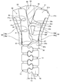
- FIG. 1 is a front view schematically showing a slide fastener according to an embodiment of the present invention.
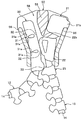
- FIG. 2 is a schematic view showing a state in which the slider is held by a stopper in the slide fastener.
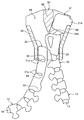
- FIG. 3 is a schematic diagram showing a state in which the left and right element rows are separated when the element row of the slide fastener is separated from the fragile portion.
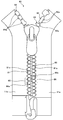
- FIG. 4 is a schematic diagram showing a state in which the slider sliding contact body is pulled out from the rear opening of the slider.
- FIG. 5 is a schematic diagram showing a state in which the slider sliding contact body is pulled out from the rear opening of the slider.
- FIG. 6 is a perspective view showing training pants to which the slide fastener is sewn.
- FIG. 7 is a schematic diagram showing a modification of the slider sliding contact body.
- FIG. 8 is a front view schematically showing a slide fastener according to a modification of the present invention.
- FIG. 9 is a front view schematically showing a conventional
- a fastener is arranged on the right fastener stringer and a slide fastener is formed by arranging a lateral punching prevention portion on the left fastener stringer.
- the right fastener stringer It is also possible to arrange a slide fastener by arranging a stopper on the left fastener stringer and arranging a horizontal prevention portion on the left side.
- the left and right element rows may be constituted by a plurality of independent synthetic resin fastener elements injection-molded on a fastener tape, or a monofilament coiled as described later. Or a continuous fastener element formed into a zigzag shape.
- FIG. 1 is a front view schematically showing a slide fastener according to an embodiment of the present invention
- FIG. 2 is a schematic view showing a state in which the slider is held by a stopper in the slide fastener.
- FIG. 2 and FIGS. 3 to 5 to be described later only the slider is shown in a cross section in order to display the positional relationship among the stopper, the pseudo element, and the horizontal pulling prevention portion accommodated in the slider. Yes.
- the tape length direction of the fastener tape is defined as the front-rear direction, and in particular, the direction in which the slider is slid to engage the left and right element rows is the front, and the slider is to be separated.
- the direction of sliding is the rear.
- the tape width direction of a fastener tape is prescribed
- the tape front and back direction of the fastener tape is defined as the vertical direction, and the side on which the slider handle is arranged is the upper side with respect to the tape surface of the fastener tape, and the opposite side is the lower side.
- the slide fastener 1 includes a pair of left and right fastener stringers 10a and 10b each provided with an element row 12 at opposite tape side edges of a pair of fastener tapes 11a and 11b, and a right fastener stringer (first fastener stringer). )
- the fastener 20 and the pseudo element 25 attached along the element row 12 to the upper end portion of 10a, and attached along the element row 12 to the upper end portion of the left fastener stringer (second fastener stringer) 10b.
- the horizontal punching prevention part 30, the opening / closing insertion tool 40 disposed at the lower ends of the left and right fastener stringers 10 a and 10 b, and the slider 50 disposed so as to be slidable along the element row 12 are provided. .
- the slider 50 which comprises the slide fastener 1 of this embodiment has the structure substantially the same as the slider conventionally used. That is, the slider 50 in this embodiment includes a slider body 51 and a handle 52 that is rotatably held by the slider body 51. Further, the slider body 51 is arranged in a direction approaching each other from the left and right side edges of the upper and lower blades 53 and 54, the upper and lower blades 53 and 54, the guide pillar 55 connecting the front end portions of the upper and lower blades 53 and 54. The left and right upper and lower flanges 56 are extended, and the handle attachment column 57 is erected in a gate shape on the upper surface of the upper wing plate 53.
- the slider 50 used in the present invention may be, for example, a slider in which flanges are arranged on the left and right side edges of either the upper wing plate 53 or the lower wing plate 54.
- Left and right shoulder openings are formed at the front end of the slider body 51 with the guide pillar 55 interposed therebetween, and a rear opening is formed at the rear end of the slider body 51. Further, a substantially Y-shaped element guide path 58 is formed between the upper and lower blades 53 and 54 to communicate the left and right shoulder openings with the rear opening.
- a tape insertion gap through which the fastener tapes 11a and 11b can be inserted is formed between the upper and lower flanges 56 arranged on the left and right sides of the slider body 51. Furthermore, in the slider 50, the upper and lower flanges 56 extend from the parallel part 56a arranged in parallel to the rear opening side of the slider 50 and the front end of the parallel part 56a, and the interval between the left and right upper and lower flanges 56 is increased. And an inclined portion 56b disposed so as to gradually increase toward the front.
- the left and right fastener stringers 10a and 10b include fastener tapes 11a and 11b and a plurality of fastener elements 13 made of synthetic resin disposed on the side edges of the tape, respectively.
- Each of the left and right fastener tapes 11a and 11b is woven or knitted into a narrow band, and a tape main part sewn on a fastener-attached product (for example, training pants 60 described later) and a fastener element 13 are attached.
- Element mounting portion (tape side edge).
- the core string part 14 is distribute
- a plurality of synthetic resin-made fastener elements 13 are arranged along the tape length direction by injection molding on the element mounting portion including the core string portion 14, and the plurality of fasteners
- An element row 12 is formed by the elements 13.
- the material of the fastener element 13 is not limited.
- a synthetic resin such as polyacetal, polypropylene, polybutylene terephthalate, nylon, or polycarbonate can be suitably used.
- each fastener element 13 includes an oval mesh head 13a, a body 13b fixed to the fastener tapes 11a and 11b so as to sandwich the core string 14, and the mesh head 13a and the body. And a neck portion 13c formed so as to be confined between 13b.
- a fragile portion 15 that locally eliminates the meshing force of the left and right element rows 12 is provided in the central portion of the element row 12 in the tape length direction (front-rear direction).
- the fragile portion 15 is formed by replacing the normal fastener element 13 having the meshing head portion 13a, the neck portion 13c, and the body portion 13b with two fastener elements having only the body portion 13b and the neck portion 13c. It is formed by being attached to the element attachment portions of the left and right fastener tapes 11a and 11b one by one.
- the element row 12 By applying a lateral pulling force to the fragile portion 15 provided in the element row 12, the element row 12 can be easily opened in the left-right direction at the fragile portion 15, and further, forward and backward from the fragile portion 15.
- the element rows 12 can be separated by sequentially releasing the engagement of the left and right fastener elements 13 toward the head.
- the fastener 20 of the present embodiment is attached to an element attachment portion including the core string portion 14 of the right fastener tape 11a.
- the stopper 20 includes a first stopper 21 that stops the sliding of the slider 50 and a second stopper 22 disposed between the first stopper 21 and the element row 12.
- the first and second stoppers 21 and 22 are fixed to the fastener tape 11a by injection molding a synthetic resin of the same material as the fastener element 13 onto the fastener tape 11a.
- the first stopper 21 in the fastener 20 has a main body 21a that has a rectangular shape when viewed from the front, and a stop 21b that protrudes from the main body 21a toward the tape inward side.
- the main body portion 21a of the first stopper 21 has a dimension (width dimension) in the tape width direction set smaller than the insertion width between the guide column 55 and the upper and lower flanges 56 in the slider 50, and a part of the main body portion 21a. Is formed so as to be able to enter the element guide path 58.
- the stop portion 21b of the first stop portion 21 is formed so as to contact the upper and lower flanges 56 of the slider 50 when a part of the main body portion 21a enters the element guide path 58, and this stop portion 21b. Can come into contact with the upper and lower flanges 56 to stop the slider 50 from sliding.
- the second stopper 22 in the fastener 20 has a fixing part 22a fixed to the fastener tape 11a and a slider locking part 22b extending from the fixing part 22a to the outside of the tape.
- the fixed portion 22a of the second stopper 22 is formed to have a rectangular shape when viewed from the front side, and the side edge (right side edge) on the tape inner side of the fixed portion 22a is the first edge.
- the thickness dimension (vertical dimension) of the fixing portion 22a in the second stopper 22 is set to be larger than the interval of the tape insertion gap of the slider 50, and between the inner surfaces of the upper and lower blades 53 and 54 of the slider 50. It is set smaller than the interval.
- the slider locking portion 22b of the second locking portion 22 is formed to have the same thickness dimension as that of the fixing portion 22a.
- a hole 22c penetrating in the front-rear direction is provided at the center of the slider locking portion 22b. Since the slider locking portion 22b has the hole 22c, the slider locking portion 22b can be elastically deformed so as to contract at least in the tape width direction.
- the maximum dimension in the tape width direction of the second stopper 22 that is, the opposite side edge (slider engagement) facing the fastener stringer 10 b on the left side of the slider locking part 22 b from the sliding contact edge of the fixing part 22 a.
- the maximum dimension in the tape width direction (to the left side edge of the stopper 22b) is set to be larger than the insertion width between the guide column 55 and the upper and lower flanges 56 in the element guide path 58 of the slider 50.
- the insertion width between the guide column 55 of the slider 50 and the upper and lower flanges 56 is a distance between the guide column 55 and the upper and lower flanges 56, and in particular, from the side wall of the guide column 55 to the inner wall surface of the upper and lower flange 56.
- the distance of the straight line when the distance is the shortest when the lines are connected by a straight line.
- the outer peripheral surface of the slider locking portion 22b has at least a first side wall surface 22d, a second side wall surface 22e, and a third side wall surface 22f.
- the first side wall surface 22d of the slider locking portion 22b is disposed to face the first stopper portion 21 and is disposed on the same plane as the front end surface of the fixing portion 22a.
- the second side wall surface 22e of the slider locking portion 22b is continuously formed from the first side wall surface 22d, and is formed into a smooth curved surface that bulges outward. Since the second side wall surface 22e is arranged on the slider locking portion 22b, for example, when the slider 50 is slid forward toward the stopper 20, the second stopping portion 22 is rearward from the shoulder of the slider 50. When moving inside the element guide path 58 toward the mouth side, and when the slider locking portion 22b is elastically restored, the end portion of the rear opening side of the guide column 55 of the slider 50 is locked to the second side wall surface 22e. The stop state of the slider 50 can be maintained (see FIG. 2).
- the slider 50 is moved from the state where the rear side end portion of the guide column 55 of the slider 50 is locked to the second side wall surface 22e.
- the slider locking portion 22b so that the second stopper 22 contracts in the tape width direction while the second side wall surface 22e is slidably contacted with the guide column 55 of the slider 50. It is possible to promote the elastic deformation of the slider 50 and help the second stopper 22 enter between the guide column 55 of the slider 50 and the upper and lower flanges 56.
- the third side wall surface 22f of the slider locking portion 22b is formed continuously from the second side wall surface 22e, and is dimensioned in the tape width direction at the second stop portion 22 (that is, from the sliding contact edge portion of the fixing portion 22a to the left side).
- the size in the tape width direction to the side edge portion of the slider locking portion 22b facing the fastener stringer 10b is gradually reduced rearward.
- the third side wall surface 22f is arranged on the slider locking portion 22b, for example, when the slider 50 is slid forward and the second stop portion 22 enters the element guide path 58 from the shoulder of the slider 50, While the third side wall surface 22f is in sliding contact with the guide column 55 of the slider 50, the second stopper 22 can smoothly enter the element guide path 58, and the second stopper 22 contracts in the tape width direction. Thus, the elastic deformation of the slider locking portion 22b can be promoted.
- a pseudo element 25 is disposed between the stopper 20 and the element row 12.
- the pseudo element 25 can block a part of the rear opening of the slider 50 when the slider 50 is brought into contact with the first stop 21 and stopped (FIG. 2). It is arranged in the position.
- the pseudo element 25 includes a body portion 25a fixed to the fastener tape 11a, and a head portion 25b extending from the body portion 25a to the side of the left side stringer 10b on the left side of the fastener stringer 10b and the element row 12. And have.
- the head 25b of the pseudo element 25 has a slidable contact surface that can be slidably contacted with a protrusion 33, which will be described later, of the lateral punching preventing portion 30 disposed on the left fastener stringer 10b. Further, the head portion 25b is formed by cutting out a part on the rear side so as not to mesh with the fastener element 13 disposed at the front end of the left element row 12.
- the lateral punching prevention portion 30 disposed on the left side fastener stringer 10b of the present embodiment is disposed on the front end side of the element row 12 so as to face the stopper 20.
- the horizontal punching prevention part 30 is fixed to the fastener tape 11b by injection molding a synthetic resin of the same material as the fastener element 13 onto the fastener tape 11b.
- the cross-out preventing portion 30 is formed in a substantially rectangular parallelepiped shape that is long in the tape length direction. Thereby, the contact area of the horizontal punching prevention part 30 and the fastener tape 11b can be ensured widely, and the adhering strength of the horizontal punching prevention part 30 to the fastener tape 11b can be increased.
- the horizontal cutout prevention part 30 is arranged so as to embed the core string part 14 of the fastener tape 11b.
- the core string part 14 can be protected by the horizontal punching prevention part 30, and in particular, the core string part 14 can be protected in a longer range as the horizontal punching prevention part 30 is formed longer in the tape length direction. Further, since the horizontal punching prevention part 30 is formed so as to enclose the core string part 14, the horizontal punching prevention part 30 can be more firmly fixed to the fastener tape 11b, and the horizontal punching prevention part 30 is separated from the fastener tape 11b. It becomes difficult to drop off.
- the thickness dimension in the tape front and back direction of the lateral punching prevention portion 30 is set to be constant throughout the entire portion of the lateral punching prevention portion 30 except a slit 31 described later.
- 53 is larger than the interval of the tape insertion gap formed between the upper flange extended from 53 and the lower flange 56 extended from the lower blade 54, and the inner surfaces of the upper and lower blades 53, 54 of the slider 50. It is set smaller than the interval between them.
- the horizontal punching prevention part 30 When the horizontal punching prevention part 30 has such a thickness, the horizontal punching prevention part 30 can be smoothly inserted into the element guide path 58 of the slider 50. Further, since the horizontal punching prevention portion 30 has a thickness dimension for preventing horizontal punching that is set larger than the interval of the tape insertion gap of the slider 50, the horizontal punching prevention portion 30 is placed in the element guide path 58 of the slider 50. Even when the slide fastener 1 is subjected to a lateral pulling force when being accommodated (that is, when the left and right fastener stringers 10a and 10b are in a closed state), the lateral punching prevention portion 30 is placed on the upper and lower flanges 56 of the slider 50. It can be made to contact reliably. Therefore, the horizontal punching prevention part 30 is not pulled out from the element guide path 58 of the slider 50 via the tape insertion gap, and the horizontal punching prevention part 30 can be stably held in the element guide path 58.
- the left side surface on the tape inward side of the lateral punching preventing portion 30 and the right side surface facing the fastener 20 are arranged in parallel with each other, and the width dimension in the tape width direction of the horizontal punching prevention portion 30 which is the distance between the left and right side surfaces is different from that of the guide column 55 of the slider 50.
- the insertion width between the flange 56 and the flange 56 is set smaller.
- the slider 50 is held by the second stop part 22 (see FIG. 2). ), And a gap formed between the second stopper 22 and the upper and lower flanges 56 on the left side of the slider 50 is set to a size that can be inserted.
- the maximum value in the tape width direction of the lateral punching prevention portion 30 is set to be smaller than the maximum value in the tape width direction of the fastener element 13.
- the lateral punching prevention portion 30 is connected to the second stop portion 22 and the upper and lower flanges 56 on the left side of the slider 50. It is possible to smoothly pull out the horizontal punching prevention portion 30 from the element guide path 58 of the slider 50 through the rear opening.
- the rear end position in the tape length direction is the position of the rear opening of the slider 50 when the slider 50 is brought into contact with the first stop portion 21 of the stopper 20 and stopped. are set to be substantially the same position.
- the front end position in the tape length direction of the lateral punching prevention portion 30 is the rear end of the guide column 55 of the slider 50 when the slider 50 is brought into contact with the first stop portion 21 of the stopper 20 and stopped.
- the left and right fastener stringers 10a and 10b are closed so as to be closer to the shoulder (front side) than the position, preferably longer in the tape length direction than the upper and lower flanges 56 of the slider 50 Are set so as to align with the front end position of the first stopper 21.
- the fixing strength of the lateral punching preventing portion 30 to the fastener tape 11b can be stably secured.
- the core string part 14 of the fastener tape 11b can be protected in a wider range by the side punching prevention part 30, and particularly when the slider 50 is brought into contact with the first stop part 21 of the stopper 20 and stopped.
- the core string portion 14 accommodated in the slider 50 is surely prevented from coming into contact with or rubbing against the upper and lower flanges 56 of the slider 50, and the core string portion 14 can be prevented from being damaged or damaged.
- the horizontal punching prevention part 30 is formed long in the tape length direction, when the slider 50 is brought into contact with the first stopper 21 of the fastener 20 and stopped, the horizontal punching prevention part 30 is moved to the slider. 50 element guide paths 58 can be deeply accommodated. For this reason, even if the left and right fastener stringers 10a, 10b in the closed state receive a lateral pulling force, the lateral punching prevention portion 30 is effectively prevented from being pulled out from the element guide path 58 of the slider 50, and the left and right fasteners The closed state of the stringers 10a and 10b can be stably maintained.
- the dimension in the tape length direction of the lateral punching preventing portion 30 is set so that the front end position of the lateral punching preventing portion 30 and the front end position of the first stopper 21 are aligned, and the slider 50 is fixed to the fastener 20.
- the lateral stop preventing portion 30 is set so as to be accommodated (hidden) in the element guide path 58 of the slider 50 when the first stop portion 21 is brought into contact with and stopped, the slide The appearance of the fastener 1 can be improved.
- the transverse prevention portion 30 is configured by two slits 31 cut in the tape width direction from the left side surface on the inner side of the tape, and the size in the tape width direction is reduced by forming the slits 2.
- Two narrow portions 32 and projecting portions 33 that are arranged at the rear end portion of the cross-cut preventing portion 30 and project toward the right fastener stringer 10a are respectively provided on the front surface side and the back surface side of the fastener tape 11b. ing.
- the two slits 31 are formed from the left side surface which is the tape inward side of the lateral punching prevention portion 30, the right side surface excluding the protruding portion 33 of the lateral punching prevention portion 30 has one continuous side.
- the right side surface constitutes one plane when the side-hole preventing portion 30 is not elastically deformed in the tape width direction.
- the two narrow width portions 32 arranged in the horizontal cutout preventing portion 30 have a minimum dimension in the tape width direction in the narrow width portion 32 and a size in the tape width direction in the horizontal cutout preventing portion 30 (the slit 31 and the protruding portion 33 Preferably, it is configured to be smaller than the dimension of the side-by-side prevention portion 30 in the tape front and back direction, so that it is less than half of the size (excluding the arranged portion). Since the narrow width portion 32 having such a width dimension is arranged in the horizontal punching prevention portion 30, the horizontal punching prevention portion 30 can be elastically deformed so as to be bent in the tape width direction.
- the two narrow width portions 32 included in the cross-cut preventing portion 30 have upper and lower flanges 56 with respect to the slider 50 when the slider 50 is brought into contact with the first stop portion 21 of the stopper 20 and stopped. It arrange
- the dimension of the tape front-and-back direction of the horizontal punching prevention part 30 in this embodiment is set larger than the dimension of the tape width direction of the narrow width part 32, the horizontal punching prevention part 30 is elastic in the tape front-back direction. It is difficult to deform.
- the two slits 31 arranged in the horizontal punching prevention part 30 are provided in a predetermined size so that the narrow width part 32 has the dimensions in the tape width direction as described above, and these slits 31 are provided.
- the fastener tape 11b and a part of the core string part 14 are exposed.
- a pair of protrusions projecting in the tape length direction so that the slit width (interval in the tape length direction) at the opening side end portion is narrowed at the opening side end portion (left end portion) of each slit 31.
- the overhang part 31a is arranged.
- the overhanging portion 31 a is arranged at the opening side end portion of the slit 31, so that, for example, the left and right element rows 12 are separated from the fragile portion 15, and the transverse prevention portion 30 is moved to the element guide path 58 of the slider 50.
- the upper and lower flanges 56 of the slider 50 are fitted into the slits 31 of the side-cut preventing part 30 and the side-cut preventing part 30 is caught by the slider 50.
- the pair of overhanging portions 31 a is arranged at the opening side end portion of the slit 31, so that the pair of overhanging portions 31 a are elastic of the lateral punching prevention portion 30.
- a deformation limiting mechanism is configured to limit the deformation amount to a predetermined range. That is, when elastically deforming the side-cut preventing portion 30 so as to bend in a concave shape toward the inner side of the tape, the pair of overhang portions 31a arranged at the opening side end portions of the slits 31 abut each other.
- the amount of elastic deformation of the side wall preventing portion 30 can be regulated.
- the anti-extraction portion 30 when the front end portions of the left and right fastener stringers 10a and 10b in the closed state receive a lateral pulling force and the side pull-out preventing portion 30 is elastically deformed so as to bend toward the upper and lower flanges 56 side of the slider 50, although the anti-extraction portion 30 is elastically deformed in the element guide path 58 of the slider 50, the anti-extraction portion 30 can be prevented from contacting the inclined portion 56b of the upper and lower flanges 56 of the slider 50, or the upper and lower flanges Even if it contacts the 56 inclined portions 56b, the load applied to the inclined portion 56b can be reduced.
- the projecting portion 33 disposed at the rear end portion of the lateral punching prevention portion 30 is disposed so as to project in the tape width direction toward the right fastener stringer 10a, and the thickness dimension of the projecting portion 33 is to prevent lateral ejection. It is set to the same size as the main body portion of the portion 30.
- the side wall preventing portion 30 is viewed from the front side, the side edge of the protruding portion 33 facing the right fastener stringer 10a is formed in an arc shape, and the peripheral surface of the protruding portion 33 is the slider 50.
- the guide column of the slider 50 is used.
- the slider 50 slides while the rear opening side end portion 55 abuts against the projecting portion 33 of the side wall preventing portion 30, thereby assisting the operation of splitting the element row 12 to the left and right, and the left and right elements in the meshing state
- the rows 12 can be separated smoothly.
- the protrusion 33 of the side-cut preventing portion 30 is a pseudo element. 25, and the pseudo element 25 is rotated to form an opening (clearance) at the rear opening of the slider 50 through which the horizontal punching prevention portion 30 can pass. (See FIGS. 3 to 5).
- the separation / insertion tool 40 disposed at the lower ends of the left and right fastener stringers 10a, 10b is a first separation / insertion member 41 (referred to as a box bar) disposed on the right fastener stringer 10a.
- a second separation / insertion member 42 (sometimes called a butterfly stick) disposed on the left fastener stringer 10b.
- the first and second separation / insertion members 41, 42 are arranged across the tape front and back surfaces of the fastener tapes 11 a, 11 b so as to be continuous from the rear end portions of the left and right element rows 12.
- the second separation / insertion members 41 and 42 are formed by injection-molding synthetic resin of the same material as the fastener element 13 onto the fastener tapes 11a and 11b, so that the shape on the tape surface side around the fastener tapes 11a and 11b is obtained. It is formed so that the shape on the back side of the tape is symmetrical.
- the first separation / insertion member 41 is arranged so as to be continuous from the element row 12, and is provided with a slider holding portion 41a fixed to the fastener tape 11a, and extends rearward from the slider holding portion 41a.
- the thickly formed pivoting portion 41c, the slider holding portion 41a and the reinforcing portion 41d extending inward from the pivoting portion 41c, and the second separation / insertion member 42 of the slider holding portion 41a are opposed to each other.
- a concave groove portion (not shown) provided on the left side surface and the inner peripheral surface of the pivot stop portion 41c.
- the slider holding portion 41a is inserted into the element guide path 58 of the slider 50 when the slider 50 is slid rearward and brought into contact with the step portion 41b. Is configured to be held in a state of being in contact with the stepped portion 41b.
- the pivoting portion 41c extends rearward from the slider holding portion 41a and is further curved to the second opening / closing insertion member 42 side. When the pivoting portion 41c is viewed from the front side, the pivoting portion 41c is substantially curved. It has a J-shape.
- the pivot 41c has an inner peripheral surface that is pivotally engaged with a later-described pivoted portion 42b of the second separation / insertion member 42, and holds the slider 50 on the slider holder 41a. When this is done, a pivot space is formed between the rear opening side end portion of the slider 50 and the pivot stop portion 41c so that a later-described pivoted stop portion 42b of the second separation / insertion member 42 can be inserted. It is configured.
- the second separation / insertion member 42 includes a plate-like main body portion 42a fixed to both the front and back surfaces of the fastener tape 11b, and a pivoted stop portion 42b disposed at the right corner of the rear end portion of the main body portion 42a.
- the protrusion 42c is disposed along the left edge of the main body 42a, and the protrusion 42d is disposed at the front end of the main body 42a.
- the main body 42a has a thickness dimension set smaller than the interval of the tape insertion gap of the slider 50.
- the pivoted portion 42b is formed in a columnar shape protruding in the vertical direction from the front and back surfaces of the main body portion 42a.
- the thickness dimension of the pivoted portion 42b is set to be larger than the interval of the tape insertion gap of the slider 50 and smaller than the interval in the vertical direction of the element guide path 58 of the slider 50.
- the protrusion 42d has a meshing portion so as to be able to mesh with the fastener element 13 arranged on the most rear end side in the element row 12 of the right fastener stringer 10a.
- the second separation / insertion member 42 is the first separation.
- the locking operation for locking the fitting member 41 can be arbitrarily selected from the following two types of operations.
- the first opening / closing fit is performed without passing the pivoted stop portion 42b of the second opening / closing fitting member 42 through the element guide path 58 of the slider 50.
- the operation of locking the first separation / insertion member 41 by inserting from the side of the insertion member 41 will be described.
- the slider 50 When performing this first locking operation, first, the slider 50 is slid toward the first separation / insertion member 41, and the slider 50 is held by the slider holding portion 41a. Next, the pivoted portion 41 b of the second separation / insertion member 42 is pivoted through a gap formed between the pivotal portion 41 c of the first separation / insertion member 41 and the slider 50. Is brought into contact with the inner peripheral surface of As a result, the second separation / insertion member 42 is locked to the first separation / insertion member 41.
- the second separation / insertion member 42 is rotated toward the first separation / insertion member 41 around the pivoted portion 42b, and the main body 42a of the second separation / insertion member 42 is moved to the slider. It is inserted into the element guide path 58 through 50 tape insertion gaps. As a result, the left and right element rows 12 are positioned so that stable meshing can be performed. Thereafter, by sliding the slider 50 held by the slider holding part 41a upward, the slide fastener 1 can be closed by meshing the left and right element rows 12.
- the slider 50 is held by the slider holding portion 41a.
- the pivoted portion 42 b of the second separation / insertion member 42 is inserted from the shoulder opening of the slider 50 and passed through the element guide path 58 of the slider 50, so that the first separation / insertion member 41 is pivoted. It is made to contact
- the 2nd opening / closing insertion member 42 is latched by the 1st opening / closing insertion member 41, and the left and right element row
- the slide fastener 1 can be closed by meshing the left and right element rows 12.
- the anti-extraction part 30 enters the element guide path 58 from the shoulder of the slider 50, and then the second stop 22 and the first stop 21 of the fastener 20 are connected to the shoulder of the slider 50 following the pseudo element 25. To the element guide path 58 sequentially.
- the sliding contact edge of the second stopper 22 is arranged on the right side of the slider 50. While being in sliding contact with the flange 56, the slider engaging portion 22 b of the second stopper 22 passes between the guide column 55 and the right upper and lower flanges 56 while being elastically deformed.
- sliding of the slider 50 can be stopped by the stop portion 21 b disposed on the first stop portion 21 coming into contact with the upper and lower flanges 56 of the slider 50. Further, at the same time when the stop portion 21b of the first stop portion 21 abuts on the upper and lower flanges 56 of the slider 50 or immediately before it abuts on the upper and lower flanges 56 of the slider 50, the slider engaging portion 22b of the second stop portion 22 Then, the rear end of the guide column 55 of the slider 50 is brought into contact with the slider locking portion 22b. Thereby, the slider 50 stopped by the first stopper 21 can be reliably supported by the second stopper 22 and the stopped state of the slider 50 can be stably held.
- the side-cut preventing portion 30 disposed on the left fastener stringer 10 b is connected to the element guide path 58 of the slider 50. It is in a state of being completely accommodated inside. Further, the pseudo element 25 disposed on the right fastener stringer 10a is in a state where the head of the pseudo element 25 is in contact with (or in the proximity of) the protruding portion 33 of the side-cut preventing portion 30. It is located to close a part of the rear entrance.
- the slide fastener 1 can be completely closed by engaging the entire left and right element rows 12 from the state in which the left and right fastener stringers 10a and 10b are separated.
- the left and right fastener tapes 11a and 11b are disposed, for example, on the front end portion where the stopper 20 of the slide fastener 1 is disposed.
- the first and second stoppers 21 and 22 are formed thicker than the tape insertion gap of the slider 50.
- the first and second stoppers 21 and 22 can be held in the element guide path 58 of the slider 50 by contacting the upper and lower flanges 56 on the right side of the slider 50.
- the side-cut prevention part 30 disposed on the left fastener stringer 10b has a high fixing strength with the fastener tape 11b and is formed thicker than the tape insertion gap of the slider 50.
- the slider 50 can be held in the element guide path 58 of the slider 50 by making contact with the upper and lower flanges 56 on the left side of the slider 50.
- the side wall preventing portion 30 of the present embodiment is longer than the dimension in the tape length direction from the rear opening of the slider 50 to the rear end position of the guide column 55, and further, the tape length of the upper and lower flanges 56 of the slider 50. Since it is formed longer than the dimension in the vertical direction, the lateral punching prevention portion 30 can be reliably brought into contact with the upper and lower flanges 56 of the slider 50 and stably held in the element guide path 58 of the slider 50.
- the first and second stoppers 21 and 22 and the lateral punching prevention part 30 are stably held in the element guide path 58 of the slider 50.
- the pseudo element 25 disposed on the right fastener stringer 10a and the protruding portion 33 of the laterally preventing portion 30 disposed on the left fastener stringer 10b are held in contact with each other, and the laterally preventing portion The pseudo element 25 prevents 30 from exiting from the element guide path 58 of the slider 50 through the rear opening. For this reason, the meshing state of the left and right element rows 12 can be held more stably.
- the two narrow width portions 32 are disposed on the lateral punching prevention portion 30 disposed on the left fastener stringer 10b.
- the front end portion of the slide fastener 1 receives a lateral pulling force
- the left and right fastener tapes 11a and 11b are pulled in directions away from each other, and therefore, the lateral punching prevention portion 30 disposed on the left fastener stringer 10b is provided.
- the slider 50 is elastically deformed so as to bend toward the upper and lower flanges 56 on the left side.
- the two narrow width portions 32 are arranged on the front side (shoulder side) side of the parallel portion 56a of the upper and lower flanges 56 of the slider 50.
- the prevention part 30 is elastically deformed mainly on the front side of the parallel part 56a.
- projection parts 31a are distribute
- a deformation limiting mechanism is configured to limit the amount of elastic deformation so as not to be deformed.
- the lateral punching prevention portion 30 abuts on the parallel portion 56a of the left flange of the slider 50, but prevents lateral withdrawal on the front side of the parallel portion 56a.
- the cross-out preventing portion 30 it is possible to prevent the cross-out preventing portion 30 from contacting the inclined portion 56 b of the upper and lower flange 56 of the slider 50, or to contact the inclined portion 56 b of the upper and lower flange 56.
- the pressing force applied to the inclined portion 56b can be reduced.
- the flange inclined portion 56b is less likely to receive the pressing force from the side-cut preventing portion 30. For this reason, even if the left and right fastener stringers 10a and 10b receive a lateral pulling force and the upper and lower flanges 56 of the slider 50 are pressed by the stopper 20 and the horizontal punching prevention portion 30, the slider 50 is moved backward (the separation direction of the element rows 12). The slider 50 becomes difficult to work on the slider 50, and the slider 50 slides backward by releasing the holding state of the second locking portion 22 by the slider locking portion 22b against the user's intention. Can be prevented. Therefore, the meshing state of the left and right element rows 12 can be held more stably.
- the second stopper that is in contact with the rear opening side end of the guide pillar 55 of the slider 50 is used.
- the portion 22 moves relatively toward the shoulder opening side of the slider 50.
- the guide column 55 of the slider 50 presses the slider locking portion 22b of the second stop portion 22 to elastically deform the slider lock portion 22b, and the second stop portion 22 is moved to the guide column 55 of the slider 50.
- the left and right element rows 12 can be separated by smoothly sliding the slider 50 backward. Then, after the slider 50 is slid to the end on the separation / insertion tool 40 side, the second separation / insertion member 42 of the separation / insertion tool 40 is removed from the first separation / insertion member 41. By doing so, the slide fastener 1 can be opened by separating the left and right fastener stringers 10a, 10b.
- the left and right element rows starting from the fragile portion 15 from the state where the slider 50 is held by the second stop portion 22 and the slide fastener 1 is closed (FIG. 2).
- An operation when the left and right fastener stringers 10a and 10b are separated by separating the left and right fastener strings 10a and 10b will be described.
- the left and right element rows 12 can be separated from the fragile portion 15 by applying a stress such as a lateral pulling force to the fragile portions 15 provided in the element row 12, and the left and right fastener stringers 10a. , 10b can be separated in order from the left and right element rows 12 to the front end portion and the rear end portion while the slider 50 is held by the second stop portion 22.
- the left fastener stringer 10b is further pulled, thereby pulling the left fastener stringer 10b as shown in FIG.
- the protruding portion 33 of the laterally preventing portion 30 disposed on the side presses the pseudo element 25 disposed on the right fastener stringer 10a.
- the pseudo element 25 receives a pressing force from the protruding portion 33 of the side wall preventing portion 30, the pseudo element 25 rotates counterclockwise when viewed from the front, thereby being blocked by the pseudo element 25.
- a clearance is formed at the rear opening of the slider 50 through which the side-cut preventing portion 30 can be inserted.
- the side-cut prevention unit 30 is easily pulled out from the element guide path 58 through the clearance formed at the rear port while sliding on the pseudo element 25 (see FIGS. 4 and 5).
- the lateral punching preventing portion 30 has the narrow width portion 32, it can be elastically deformed so as to bend in the tape width direction, and the protruding portion 33 of the lateral punching preventing portion 30 is excluded.
- the right side surface constitutes one continuous surface. Therefore, even if the lateral punching prevention portion 30 is formed long in the tape length direction as described above, it is arranged on the guide column 55 of the slider 50 and the right fastener stringer 10a while being elastically deformed as necessary. Without being caught by the second stopper 22 or the pseudo element 25, the element 50 is smoothly inserted into the element guide path 58 of the slider 50 and pulled out through the rear opening of the slider 50.
- the slide fastener 1 of the present embodiment when used for the training pants 60 as described later, when the left and right element rows 12 are separated from the fragile portion 15, the left fastener stringer 10b is replaced with the right fastener.
- the stringer 10a may be pulled diagonally downward to the left.
- the lateral punching prevention portion 30 is elastically deformed when pulled out from the element guide path 58 of the slider 50, so that the guide column of the slider 50 55, the horizontal stopper 22 can be smoothly pulled out via the rear opening of the slider 50 without being caught by the second stopper 22 and the pseudo element 25.
- a pair of overhang portions 31a are arranged at the opening side end portion of the slit 31 in the side wall preventing portion 30, and the slit width at the opening side end portion is narrowed. Further, when the side-through preventing portion 30 is bent toward the upper and lower flanges 56 on the left side of the slider 50 due to elastic deformation, the slit width at the opening side end portion of the slit 31 is further narrowed by the protruding portion 31a.
- the upper and lower flanges on the left side of the slider 50 are inserted into the slit 31 of the horizontal punching prevention part 30 when the horizontal punching prevention part 30 is pulled out from the slider 50. 56 can be prevented from being caught. Therefore, in the present embodiment, a trouble caused by the upper and lower flanges 56 of the slider 50 being sandwiched between the slits 31 of the horizontal punching prevention part 30, for example, the horizontal punching prevention part 30 is caught by the vertical flange 56 when the horizontal punching prevention part 30 is pulled out.
- the left fastener stringer 10b is pulled to completely pull out the transverse prevention portion 30 from the slider 50, whereby the left and right fastener stringers 10a and 10b can be pulled apart to open the slide fastener 1.
- the slide fastener 1 of the present embodiment by applying a lateral pulling force to the fragile portion 15 provided in the element row 12, the slider 50 can be moved from the fragile portion 15 to the left and right without sliding operation.
- the slide fastener 1 can be opened by separating the element rows 12 easily and quickly.
- the slide fastener 1 of the present embodiment as described above is preferably used as a fastener-attached product, for example, for training pants 60 as shown in FIG.
- a fastener-attached product for example, for training pants 60 as shown in FIG.
- the training pants 60 to which the slide fastener 1 of the present embodiment is attached will be described.
- the fastener-attached product to which the slide fastener 1 of the present invention is attached is not limited to the training pants 60, and can be applied to various other products.
- the training pants 60 shown in FIG. 6 are made using a material having excellent elasticity.
- the slide fastener 1 according to this embodiment is sewn from one end portion on the waist portion side to the other end portion on the hem side of the left and right leg portions 61.
- the slide fastener 1 shown in FIG. 1 and the slide fastener 1 shown in FIG. 6 are viewed, although the slide fastener 1 has different length dimensions, the substantial configuration is the same for both slide fasteners 1. is there.
- the end portion (front end portion) of the slide fastener 1 on the side where the fasteners 20 and the lateral punching prevention portions 30 are arranged is the waist portion of the training pants 60.
- the slide fastener 1 is placed on the training pants 60 such that the end (rear end) of the slide fastener 1 on which the separation fitting 40 is placed is arranged on the hem side of the training pants 60. Is attached.
- the fragile portion 15 of the element row 12 is provided near the knee portion of the left and right leg portions 61.
- Such training pants 60 are separated by separating the element rows 12 of the slide fasteners 1 arranged on the left and right leg portions 61 and pulling away the corresponding pair of fastener stringers 10a and 10b. Is configured to open into a front piece and a back piece.
- the training pants 60 in which the slide fastener 1 of the present embodiment is sewn on the left and right leg portions 61 separates the element row 12 by sliding the slider 50 to the end portion on the side of the separation fitting 40, for example. Since the fastener stringers 10a and 10b of the slide fasteners 1 are separated by separating the first and second separation / insertion members 41 and 42 of the separation / insertion tool 40, the training pants 60 are removed from the form of the pants.
- the left and right leg portions 61 can be changed into a form in which the front piece portion and the rear piece portion are opened. Further, the training pants 60 having the left and right leg portions 61 opened in the front piece portion and the rear piece portion are slid into the form of the pants again by sliding the sliders 50 of the slide fasteners 1 to engage the element rows 12. Can be returned.
- training pants 60 have the form of pants, they can be put on and taken off in the same manner as conventional general training pants.
- a lateral pulling force is easily applied to the front end portion of the slide fastener 1 on the side of the fastener 20.
- the slide fastener 1 of the present embodiment is stably held by the second stopper 22 when the slider 50 comes into contact with the first stopper 21 and stops as described above. Even if the end portion (front end portion) on the fastener 20 side of the fastener 1 receives a lateral pulling force, a force that causes the slider 50 to slide toward the separation / insertion insertion device 40 side (rear) becomes difficult to act on the slider 50. It is configured as follows.
- the slider 50 does not depend on human hands.
- the knee part of the front part of the training pants 60 is gripped and pulled forward so that the weak parts 15 arranged on the slide fasteners 1 By applying a pulling force, the element row 12 of the slide fastener 1 can be separated into the stopper 20 side and the separation fitting insert 40 side, starting from the weakened portion 15.
- the lateral punching prevention portion 30 disposed on the left fastener stringer 10b Pulled on.
- the horizontal punching prevention portion 30 from the element guide path 58 of the slider 50 and separate the pair of fastener stringers 10a and 10b disposed on the respective leg portions 61.
- the left and right legs 61 of the training pants 60 open to the front piece and the back piece, so that the training pants 60 can be easily and quickly put on, for example, while wearing competition shoes. You can take it off.
- the shape and dimension of the horizontal penetration prevention part 30 and the fastener 20, and the form of the fastener element 13 or the weak part 15 are not limited to the said embodiment, As needed, it is arbitrary. It is possible to change.
- the horizontal punching prevention portion in the present invention has a tape front and back dimension larger than the interval of the tape insertion gap of the slider and has at least one narrow width portion, for example, ( It is also possible to adopt the forms shown in a) to (d).
- the lateral punching prevention portion 71 shown in FIG. 7A is configured such that each slit 71a forming the narrow width portion 71b is arranged along the tape width direction from the right edge of the lateral punching prevention portion 71. Yes.
- the horizontal punching prevention portion 72 shown in FIG. 7B is formed from the left edge where the slit 72a forming the narrow width portion 72b on the rear side hits the tape inner side of the horizontal punching prevention portion 71, and
- the slit 72c that forms the narrow side portion 72d on the front side is formed from the right edge of the transverse prevention portion 71.
- the side-cut preventing portions 71 and 72 have a length dimension in the tape length direction and a thickness dimension in the tape front and back direction equivalent to the side-cut preventing portion 30 in the above-described embodiment. Moreover, it has the adhering strength with respect to the fastener tape 11b substantially equivalent to the horizontal penetration prevention part 30 in the above-mentioned embodiment.
- 7A and 7B are made to be bent in the tape width direction by the narrow width portions 71b, 72b, 72d formed by the slits 71a, 72a, 72c. It is configured to be elastically deformable.
- a core string portion of a fastener tape is disposed at the opening side end portion (right end portion) of each slit 71a.
- the core string part of a fastener tape is distribute
- the core string part of a fastener tape is arranged at the opening side end part of the slits 71a and 72c, the core string part itself is configured to be difficult to expand and contract, so that the same core string part is prevented from being cut out. It is possible to configure a deformation limiting mechanism that limits the amount of elastic deformation 72 to a predetermined range. 7B, it is possible to configure a deformation limiting mechanism by providing a protruding portion at the opening side end of the rear slit 72a.
- the horizontal hole preventing part 30 according to the above-described embodiment and the horizontal hole preventing parts 71 and 72 shown in FIGS. 7A and 7B each have two narrow width parts formed by slits. Although it has, in this invention, the number of the narrow width part distribute
- a concave fitting portion 73a is arranged along the tape length direction at the center of the lateral punching prevention portion 73 in the tape width direction. Since this horizontal cutout preventing portion 71 has a concave fitting portion 73a, a tape width direction dimension of the horizontal cutout preventing portion 71 is reduced in the tape length direction region where the concave fitting portion 73a is disposed. A width portion 73b is configured.
- two concave fitting portions 74a are independently arranged at the central portion of the lateral punching prevention portion 74 in the tape width direction.
- the narrow fitting portion 74b in which the dimension in the tape width direction of the side-cut preventing portion 71 is reduced is constituted by these concave fitting portions 74a.
- the side-cut preventing portions 73 and 74 have a length dimension in the tape length direction and a thickness dimension in the tape front and back direction equivalent to the side-cut preventing portion 30 in the above-described embodiment.
- the narrow width portions 73b and 74b formed by the recessed fitting portions 73a and 74a are configured to be elastically deformable so as to be bent in the tape width direction.
- the lateral punching prevention portions 71 to 74 are elastically deformed, thereby It is possible to smoothly pull out the side-cut preventing portions 71 to 74 from the slider while minimizing interference with the slider.
- the side-cut preventing part 30 according to the above-described embodiment and the side-cut preventing parts 71 to 74 shown in FIGS. 7 (a) to 7 (d) are exposed in the slit or the recessed fitting part.
- the synthetic resin is excluded from the inside of the slit or the recessed fitting portion.
- the horizontal hole preventing parts 30, 71 to 74 are desired depending on the selection of the synthetic resin material. If elastic deformation can be ensured, the bottoms may be formed in the slits or recessed fitting portions of the side-hole preventing portions 30, 71 to 74.
- the fastener element 81, the second stop portion 82, the pseudo element 83, and the lateral punching prevention portion 84 are connected to the fastener tapes 11a and 11b.
- the fastener tapes 11a and 11b In order to increase the fixing strength and to prevent the upper and lower flanges 56 of the slider 50 and the fastener tapes 11a and 11b from rubbing when the slider 50 slides, it projects from the tape side edge of the fastener element 81 and the like toward the inside of the tape.
- the fin portions 81a, 82a, 83a, and 84a can be provided respectively.
- the slider locking portion 22b that can be elastically deformed in the tape width direction is disposed on the second stop portion 22 of the stopper 20, but depending on the use of the slide fastener, etc. It is possible to arbitrarily select whether or not to arrange the slider locking portion on the second stopping portion. Therefore, in the present invention, as shown in FIG. 8, the second stopper 82 can be configured without providing the slider locking portion.
- the form of the fragile portion is not particularly limited as long as the meshing force of the left and right element rows can be locally reduced or eliminated in the fragile portion arranged in the element row.
- the weakened portion 86 is not a fastener element in which the meshing head is eliminated as in the above-described embodiment, but the size of the meshing head is smaller than the other fastener elements 81. It is also possible to configure the fastener element 86a by attaching it to the fastener tapes 11a and 11b.
Abstract
In this slide fastener (1, 80), a fragile section (15, 86) is provided to an element row (12), and it is possible to detach the element row (12) in an engaged state from the fragile section (15, 86) and to separate first and second fastener stringers (10a, 10b). Lateral withdrawal prevention sections (30, 71, 72, 73, 74, 84) are arranged on the second fastener stringer (10b). The lateral withdrawal prevention sections (30, 71, 72, 73, 74, 84) have a larger thickness, for preventing lateral withdrawal, than the spacing of a tape insertion and passage gap of a slider (50). The lateral withdrawal prevention sections (30, 71, 72, 73, 74, 84) have at least one small-width section (32, 71b, 72b, 72d, 73b, 74b) at a portion provided with a thickness for preventing lateral withdrawal. Even when the slide fastener (1, 80) receives a lateral pulling force, the lateral withdrawal prevention sections (30, 71, 72, 73, 74, 84) are thereby held in the slider (50), and a closed state can be maintained. It is also possible, when the element row (12) is detached from the fragile section (15, 86), to pull out the lateral withdrawal prevention sections (30, 71, 72, 73, 74, 84) from the slider (50) in a smooth manner.
Description
本発明は、エレメント列に噛合力を局部的に低下させた脆弱部が配され、その脆弱部から左右のエレメント列の噛合を解除して左右のファスナーストリンガーを分離させることが可能なスライドファスナーに関する。
The present invention relates to a slide fastener capable of separating left and right fastener stringers by disengaging the left and right element rows from the weakened portion, in which a weakened portion in which the engagement force is locally reduced is arranged in the element row. .
例えば国際公開第2006/103438号パンフレット(特許文献1)には、左右のエレメント列の噛合を迅速に解除して、左右のファスナーストリンガーを分離させることが可能なスライドファスナーが開示されている。このようなスライドファスナーは、緊急開口ファスナーと呼ばれることがあり、ライフジャケットなどに用いられるようになってきている。
For example, International Publication No. 2006/103438 pamphlet (Patent Document 1) discloses a slide fastener that can quickly disengage the left and right element rows to separate the left and right fastener stringers. Such a slide fastener is sometimes referred to as an emergency opening fastener and has been used for a life jacket or the like.
以下、特許文献1に記載されているスライドファスナーについて、図9を参照しながら説明する。なお、以下の説明において、ファスナーテープのテープ長さ方向を前後方向と規定し、特に左右のエレメント列を噛合させるようにスライダーを摺動させる向きを前方とし、エレメント列の噛合を解除するようにスライダーを摺動させる向きを後方とする。
Hereinafter, the slide fastener described in Patent Document 1 will be described with reference to FIG. In the following description, the tape length direction of the fastener tape is defined as the front-rear direction, and in particular, the direction in which the slider is slid so as to engage the left and right element rows is the front, and the engagement of the element rows is released. The direction in which the slider slides is the rear.
また、ファスナーテープのテープ幅方向を左右方向と規定し、スライドファスナーを正面側から見たときの左側を左方とし、右側を右方とする。更に、ファスナーテープのテープ表裏方向を上下方向と規定し、ファスナーテープのテープ面に対してスライダーの引手が配される側を上方とし、その反対側を下方とする。
Also, the tape width direction of the fastener tape is defined as the left-right direction, and the left side when the slide fastener is viewed from the front side is the left side, and the right side is the right side. Furthermore, the tape front and back direction of the fastener tape is defined as the vertical direction, and the side on which the slider handle is arranged is the upper side with respect to the tape surface of the fastener tape, and the opposite side is the lower side.
特許文献1に記載されているスライドファスナー90は、左右のファスナーテープ92のテープ側縁部にエレメント列93が形成された左右一対のファスナーストリンガー91と、エレメント列93に沿って摺動可能に取着されたスライダー94と、右側のファスナーテープ92におけるエレメント列93の一端側(前端側)に配された止具95と、左右のファスナーテープ92におけるエレメント列93の他端側(後端側)に配された開離嵌挿具96とを有している。
The slide fastener 90 described in Patent Document 1 is slidable along a pair of left and right fastener stringers 91 in which an element row 93 is formed on the side edges of the left and right fastener tapes 92 and the element row 93. The attached slider 94, a stopper 95 disposed on one end side (front end side) of the element row 93 in the right fastener tape 92, and the other end side (rear end side) of the element row 93 in the left and right fastener tapes 92. And an open / close insert 96.
このスライドファスナー90において、左右のファスナーテープ92の対向するテープ側縁には芯紐部92aが配されており、同芯紐部92aを含むファスナーテープ92のテープ側縁部に複数のファスナーエレメント93aが所定の間隔をもって取着されることによって、エレメント列93が形成されている。更に、左右のエレメント列93には、所定個数のファスナーエレメント93aを意図的に取り除いて形成されたギャップによって脆弱部93bが設けられている。
In the slide fastener 90, a core string portion 92a is disposed on the opposing tape side edges of the left and right fastener tapes 92, and a plurality of fastener elements 93a are provided on the tape side edge portion of the fastener tape 92 including the concentric string portions 92a. Are attached at predetermined intervals to form an element row 93. Further, the left and right element rows 93 are provided with weak portions 93b by gaps formed by intentionally removing a predetermined number of fastener elements 93a.
また、右側のファスナーストリンガー91には、エレメント列93の前端側に止具95が配されているものの、左側のファスナーストリンガー91におけるエレメント列93の前端側には、止具95が配されていない。また、左側のエレメント列93の前端が、右側のエレメント列93の前端よりも後方側に位置しており、左側のエレメント列93が右側のエレメント列93よりも短く形成されている。
The right fastener stringer 91 is provided with a stopper 95 on the front end side of the element row 93, but the fastener 95 is not provided on the front end side of the element row 93 in the left fastener stringer 91. . Further, the front end of the left element row 93 is located behind the front end of the right element row 93, and the left element row 93 is formed shorter than the right element row 93.
この場合、左側のエレメント列93の最も前端側に配したファスナーエレメント93a(以下、このファスナーエレメントを、前端エレメントと記す)は、スライダー94を止具95に当接する前端位置まで摺動させて停止させたときに、スライダー94のエレメント案内路内に前端エレメント93aの一部が収容されるように配されている。
In this case, the fastener element 93a disposed on the most front end side of the left element row 93 (hereinafter, this fastener element is referred to as a front end element) is stopped by sliding the slider 94 to the front end position where it abuts against the stopper 95. When this is done, a part of the front end element 93a is accommodated in the element guide path of the slider 94.
同スライドファスナー90における開離嵌挿具96は、左側のファスナーストリンガー91の後端部にエレメント列93に沿って固着された蝶棒96aと、右側のファスナーストリンガー91の後端部にエレメント列93に沿って蝶棒96aと対向するように固着された箱棒96bと、箱棒96bの下端部に同箱棒96bと一体的に配された箱体96cとを有している。
The opening / closing insert 96 in the slide fastener 90 includes a butterfly pin 96a fixed along the element row 93 to the rear end portion of the left fastener stringer 91 and an element row 93 at the rear end portion of the right fastener stringer 91. A box rod 96b fixed so as to oppose the butterfly rod 96a along with the box rod 96b, and a box body 96c disposed integrally with the box rod 96b at the lower end of the box rod 96b.
上述のような構成を有する特許文献1のスライドファスナー90は、スライダー94を止具95に向けて前方に摺動させることにより左右のエレメント列93を噛合させ、スライダー94を止具95に当接する前端位置まで摺動させたときに、左右のファスナーストリンガー91を完全に閉鎖することができる。
In the slide fastener 90 of Patent Document 1 having the above-described configuration, the left and right element rows 93 are engaged by sliding the slider 94 forward toward the stopper 95, and the slider 94 is brought into contact with the stopper 95. When slid to the front end position, the left and right fastener stringers 91 can be completely closed.
また、スライダー94を前端位置に摺動させて停止させたときには、左側のエレメント列93の最も前端側に配した前端エレメント93aの一部が、スライダー94のエレメント案内路内に収容されるため、左右のファスナーストリンガー91がエレメント列93の前端側から分離することを防止できる。
When the slider 94 is slid to the front end position and stopped, a part of the front end element 93a arranged on the most front end side of the left element row 93 is accommodated in the element guide path of the slider 94. The left and right fastener stringers 91 can be prevented from separating from the front end side of the element row 93.
一方、この特許文献1のスライドファスナー90には、左右のエレメント列93の一部に脆弱部93bが設けられているため、左右のファスナーストリンガー91が互いに離間させる方向に強く引っ張る横引き力を受けた場合、脆弱部93bが開いて、同脆弱部93bに隣接する左右のファスナーエレメント93aからテープ長さ方向の前後方向に向けて噛み合いが解除され、左右のエレメント列93が分離していく。
On the other hand, the slide fastener 90 of Patent Document 1 is provided with a fragile portion 93b in a part of the left and right element rows 93. Therefore, the slide fastener 90 receives a lateral pulling force that strongly pulls the left and right fastener stringers 91 away from each other. In this case, the fragile portion 93b is opened, the meshing is released from the left and right fastener elements 93a adjacent to the fragile portion 93b in the longitudinal direction of the tape length direction, and the left and right element rows 93 are separated.
そして、左右のエレメント列93が前端部まで解除されると、スライダー94のエレメント案内路内にその一部が収容されていた左側の前端エレメント93aが、スライダー94の後口から引き抜かれる。また、左右のエレメント列93が後端部まで解除されると、蝶棒96aが箱体96cから抜出される。これにより、左右のファスナーストリンガー91を完全に引き離すことができる。
Then, when the left and right element rows 93 are released to the front end, the left front end element 93a, which is partially accommodated in the element guide path of the slider 94, is pulled out from the rear opening of the slider 94. When the left and right element rows 93 are released to the rear end, the butterfly stick 96a is extracted from the box 96c. Thereby, the left and right fastener stringers 91 can be completely separated.
特許文献1のスライドファスナー90では、上述のように脆弱部93bから左右のエレメント列93を分離して左右のファスナーストリンガー91を完全に引き離すことにより、スライダー94の摺動によりスライドファスナー90を開く場合に比べて、左右のファスナーストリンガー91を簡単に且つ迅速に引き離すことができる。このため、特許文献1のスライドファスナー90は、例えば緊急時に素早い対応が必要とされるライフジャケット等のようなファスナー被着製品に対して特に有効に使用される。
In the slide fastener 90 of Patent Document 1, when the left and right element string 93 is separated from the fragile portion 93b and the left and right fastener stringers 91 are completely separated as described above, the slide fastener 90 is opened by sliding the slider 94. Compared to the above, the left and right fastener stringers 91 can be easily and quickly pulled apart. For this reason, the slide fastener 90 of Patent Document 1 is particularly effectively used for fastener-attached products such as life jackets that require a quick response in an emergency, for example.
ところで、スライドファスナーは、現在においてもなおその用途が拡大しており、様々な分野の製品に取り付けられて使用されてきている。例えば、実開平4-84313号公報(特許文献2)には、スライドファスナーを、トレーニングパンツに取り付けて使用することが記載されている。
By the way, the use of slide fasteners is still expanding, and they are used by being attached to products in various fields. For example, Japanese Utility Model Publication No. 4-84313 (Patent Document 2) describes that a slide fastener is used by attaching it to training pants.
この特許文献2に記載されているトレーニングパンツは、その左右の脚部にスライドファスナーが同トレーニングパンツのウエスト側の上端部から裾側の下端部にかけて取り付けられて構成されている。このような特許文献2のトレーニングパンツによれば、左右の脚部に取着されたスライドファスナーのスライダーを摺動させて各スライドファスナーのファスナーストリンガーを分離させることにより、トレーニングパンツをパンツの形態から前身片部と後身片部の2つの部分に開くことが可能となる。
The training pants described in Patent Document 2 are configured such that slide fasteners are attached to the left and right leg portions from the upper end portion on the waist side to the lower end portion on the hem side of the training pants. According to such training pants of Patent Document 2, the training pants are removed from the form of the pants by sliding the slide fastener sliders attached to the left and right legs to separate the fastener stringers of each slide fastener. It becomes possible to open into two parts, a front piece and a back piece.
また、このように開いた前身片部と後身片部とは、左右脚部に配したスライドファスナーのスライダーを摺動させて左右のファスナーストリンガーを再び閉鎖することによって連結されるため、トレーニングパンツを元のパンツの形態に戻すことができる。
In addition, the front piece and the back piece opened in this way are connected by sliding the slide fastener sliders arranged on the left and right legs and closing the left and right fastener stringers again, so that the training pants Can be returned to its original pant form.
このような構成を有する特許文献2のトレーニングパンツは、左右両側のスライドファスナーを閉鎖した状態においては、従来の一般的なトレーニングパンツと同様に着用したり、脱いだりすることができる。また、同トレーニングパンツは、スライドファスナーの左右のファスナーストリンガーを分離して前身片部と後身片部とに分割するによって、競技用シューズやスパイクなどを履いた状態のままであっても容易に脱衣することが可能となる。
The training pants of Patent Document 2 having such a configuration can be worn or taken off in the same manner as conventional general training pants when the left and right slide fasteners are closed. In addition, the training pants can be easily worn even while wearing competition shoes or spikes by separating the left and right fastener stringers of the slide fastener into a front piece and a back piece. It is possible to undress.
特許文献2に記載されているようにスライドファスナーをトレーニングパンツに使用する場合において、トレーニングパンツに取着するスライドファスナーとして、例えば特許文献1に係るスライドファスナーを用いることにより、同スライドファスナーのエレメント列に設けた脆弱部から左右のファスナーストリンガーを簡単に且つ迅速に分離させることができるため、トレーニングパンツの脱衣を従来よりも更に簡単に且つ迅速に行うことが可能となる。
When a slide fastener is used for training pants as described in Patent Document 2, for example, by using the slide fastener according to Patent Document 1 as a slide fastener to be attached to the training pants, an element row of the slide fastener is used. Since the left and right fastener stringers can be easily and quickly separated from the fragile portion provided in the training pants, the training pants can be undressed more easily and quickly than in the past.
しかしながら、特許文献1のスライドファスナー90では、スライダー94を止具95に当接する前端位置まで摺動させて完全に引き上げた状態の場合、止具95が配されてない左側のファスナーストリンガー91において、エレメント列93よりも前方に露呈している芯紐部92aがスライダー94のエレメント案内路内に収容される。このとき、スライドファスナー90の止具95側の端部が横引き力等を受けた場合、その露呈している芯紐部92aがスライダー94のフランジに当たったり、擦れたりして同芯紐部92aが傷むことによってスライドファスナー90の耐久性を低下させるという問題があった。
However, in the slide fastener 90 of Patent Document 1, when the slider 94 is slid to the front end position in contact with the stopper 95 and completely lifted up, the fastener stringer 91 on the left side where the stopper 95 is not disposed, A core string portion 92 a exposed forward of the element row 93 is accommodated in the element guide path of the slider 94. At this time, when the end portion of the slide fastener 90 on the side of the stopper 95 receives a lateral pulling force or the like, the exposed core string portion 92a hits or rubs against the flange of the slider 94 so that the concentric string portion There was a problem that the durability of the slide fastener 90 was lowered by damaging the 92a.
ところで、スライドファスナーをトレーニングパンツに用いる場合、スライドファスナーの操作を行い易くするために、スライドファスナーの開離嵌挿具が裾側の下端部に配され、止具がウエスト側の上端部に配される。このため、スライドファスナーのエレメント列を噛合させてパンツの形態が保持されているときには、スライドファスナーのスライダーが止具に当接するウエスト部に配置される。
By the way, when using slide fasteners for training pants, in order to facilitate the operation of the slide fasteners, the slide fastener opening / closing inserts are arranged at the lower end on the hem side and the fasteners are arranged on the upper end on the waist side. Is done. For this reason, when the shape of the pants is held by meshing the element rows of the slide fastener, the slider of the slide fastener is disposed on the waist portion that contacts the stopper.
この場合、トレーニングパンツを着用したり、脱衣したりするときには、トレーニングパンツのウエスト部分が伸ばされて、そのウエスト部分に胴回り方向の張力がかかる。このため、パンツの形態のトレーニングパンツを着脱するたびに、スライダーが配置されているスライドファスナーの止具側の端部には大きな横引き力が繰り返し与えられる。
In this case, when the training pants are worn or undressed, the waist part of the training pants is stretched and tension is applied to the waist part in the waistline direction. For this reason, whenever a training pant in the form of a pant is attached or detached, a large lateral pulling force is repeatedly applied to the end of the slide fastener on which the slider is disposed on the fastener side.
このため、例えば上述のようにトレーニングパンツに取着するスライドファスナーとして、例えば特許文献1のスライドファスナーを用いた場合、トレーニングパンツを着脱するときにスライドファスナーの止具側の端部が大きな横引き力を受ける。
For this reason, for example, when the slide fastener of Patent Document 1 is used as a slide fastener to be attached to the training pants as described above, for example, when the training pants are attached / detached, the end of the slide fastener on the fastener side is largely pulled horizontally. Receive power.
ここで、特許文献1のスライドファスナー90では、左右のファスナーストリンガー91が閉鎖状態にあるときに、前述のように左側のエレメント列93の最も前端側に配した前端エレメント93aの一部が、スライダー94のエレメント案内路内に収容されている。このため、スライドファスナー90の止具95側の端部が横引き力を受けても、ある程度の大きさの横引き力まではファスナーストリンガー91の閉鎖状態を維持することができる。
Here, in the slide fastener 90 of Patent Document 1, when the left and right fastener stringers 91 are in the closed state, as described above, a part of the front end element 93a arranged on the most front end side of the left element row 93 is a slider. It is accommodated in 94 element guideways. For this reason, even if the end of the slide fastener 90 on the side of the stopper 95 receives a lateral pulling force, the closed state of the fastener stringer 91 can be maintained up to a certain amount of lateral pulling force.
しかし、スライドファスナー90の止具95側の端部が大きな横引き力を受けた場合、スライダー94の向きが傾くこと等によって、スライダー94のエレメント案内路内に収容されていた前端エレメント93aがスライダー94の後口側から抜け出し、左右のエレメント列93の噛み合いが前端側から強制的に解除される。その結果、スライドファスナー90の左右のファスナーストリンガー91が、使用者の意思に反して徐々に分離してしまい、パンツの形態を保持できないという問題があった。
However, when the end portion of the slide fastener 90 on the side of the stopper 95 receives a large lateral pulling force, the front end element 93a accommodated in the element guide path of the slider 94 is moved by the inclination of the slider 94 or the like. 94 is pulled out from the rear opening side, and the meshing of the left and right element rows 93 is forcibly released from the front end side. As a result, the right and left fastener stringers 91 of the slide fastener 90 are gradually separated against the user's intention, and there is a problem that the shape of the pants cannot be maintained.
更に、上述のようにスライドファスナー90の止具95側の端部が大きな横引き力を受けたときに、スライダー94のエレメント案内路内に収容されていた前端エレメント93a自体が、スライダー94のフランジから局所的に大きな力(荷重)を受ける。このとき、前端エレメント93aとファスナーテープ92との接触面積は小さく、ファスナーテープ92に対する前端エレメント93aの固着強度は決して高くない。そのため、前端エレメント93aがスライダー94のフランジから大きな応力を受けたときに、その前端エレメント93aがファスナーテープ92から取れてしまい、ファスナーストリンガー91の閉鎖状態を維持できないという問題があった。
Further, as described above, when the end portion of the slide fastener 90 on the side of the stopper 95 receives a large lateral pulling force, the front end element 93a itself housed in the element guide path of the slider 94 becomes the flange of the slider 94. Receives a large force (load) locally. At this time, the contact area between the front end element 93a and the fastener tape 92 is small, and the fixing strength of the front end element 93a to the fastener tape 92 is never high. Therefore, when the front end element 93a receives a large stress from the flange of the slider 94, the front end element 93a is removed from the fastener tape 92, and the closed state of the fastener stringer 91 cannot be maintained.
また、特許文献1のスライドファスナー90をトレーニングパンツに取着した場合には、エレメント列93に設けた脆弱部93bから左右のファスナーストリンガー91を分離させる際にも、スライダー94のエレメント案内路内に収容されていた前端エレメント93aがファスナーテープ92から取れて脱落し易いという問題があった。
Further, when the slide fastener 90 of Patent Document 1 is attached to the training pants, the left and right fastener stringers 91 are separated from the fragile portion 93 b provided in the element row 93, and the slider 94 is inserted into the element guide path. There was a problem that the front end element 93a accommodated could be easily removed from the fastener tape 92.
具体的に説明すると、特許文献1のスライドファスナー90では、脆弱部93bから左右のファスナーストリンガー91を分離させる際に、例えば一方のファスナーストリンガー91が斜め方向に引っ張られてしまうと、スライダー94のエレメント案内路内に収容されていた前端エレメント93aが同スライダー94のフランジに引っ掛かることがある。
Specifically, in the slide fastener 90 of Patent Document 1, when the left and right fastener stringers 91 are separated from the fragile portion 93b, for example, if one fastener stringer 91 is pulled in an oblique direction, the element of the slider 94 The front end element 93a accommodated in the guide path may be caught on the flange of the slider 94.
このとき、前端エレメント93aのファスナーテープ92に対する固着強度は上述のように決して高くないため、前端エレメント93aが、スライダー94のフランジに引っ掛かることによって、そのフランジから前端エレメント93aが大きな荷重を受けるため、前端エレメント93aがファスナーテープ92から取れて脱落するといった不具合が生じ易かった。
At this time, since the fixing strength of the front end element 93a to the fastener tape 92 is never high as described above, the front end element 93a receives a large load from the flange when the front end element 93a is hooked on the flange of the slider 94. There was a problem that the front end element 93a was easily removed from the fastener tape 92 and dropped off.
本発明は上記従来の課題に鑑みてなされたものであって、その具体的な目的は、スライダーを上止具側の端部位置で停止させた状態で横引き力を受けても、左右のファスナーストリンガーの閉鎖状態を安定して維持することが可能で、また、左右のファスナーストリンガーを脆弱部から分離させる際にスライドファスナーの構成部材を破損させることなく、左右のファスナーストリンガーを分離させることが可能なスライドファスナーを提供することにある。
The present invention has been made in view of the above-described conventional problems, and a specific object thereof is that even if the slider is stopped at the end position on the upper stopper side, The closed state of the fastener stringer can be stably maintained, and the left and right fastener stringers can be separated without damaging the components of the slide fastener when the left and right fastener stringers are separated from the fragile portion. It is to provide a possible slide fastener.
上記目的を達成するために、本発明により提供されるスライドファスナーは、基本的な構成として、一対の第1及び第2ファスナーテープの対向するテープ側縁部にエレメント列が取着された左右一対の第1及び第2ファスナーストリンガーと、前記エレメント列に沿って摺動可能なスライダーと、前記第1ファスナーストリンガーにおける前記エレメント列の一端側に配された止具と、前記エレメント列に配され、左右の前記エレメント列の噛合力を局部的に低下させた又は無くした少なくとも1つの脆弱部とを有し、前記スライダーは、上下翼板間に略Y字状のエレメント案内路を有し、前記スライダーの側縁部に前記第1及び第2ファスナーテープのテープ挿通間隙が形成され、噛合状態にある前記エレメント列を前記脆弱部から分離して前記第1及び第2ファスナーストリンガーを引き離すことが可能なスライドファスナーであって、前記第2ファスナーストリンガーにおける前記エレメント列の一端側に横抜き防止部が配され、前記横抜き防止部は、閉鎖状態にある前記第1及び第2ファスナーストリンガーが横引き力を受けたときに前記第2ファスナーテープが前記スライダーの前記エレメント案内路から前記テープ挿通間隙を介して引き抜かれることを防止すべく前記テープ挿通間隙の間隔よりも大きなテープ表裏方向の寸法を有する横抜き防止の厚さを備え、前記横抜き防止部は、横抜き防止の厚さを備えた部分に、テープ幅方向の寸法を小さくした少なくとも1つの細幅部を有してなることを最も主要な特徴とするものである。
In order to achieve the above object, a slide fastener provided by the present invention has, as a basic structure, a pair of left and right elements in which element rows are attached to opposing tape side edges of a pair of first and second fastener tapes. The first and second fastener stringers, a slider slidable along the element row, a stopper disposed on one end side of the element row in the first fastener stringer, and the element row, At least one weakened portion in which the meshing force of the left and right element rows is locally reduced or eliminated, and the slider has a substantially Y-shaped element guide path between the upper and lower blades, A tape insertion gap for the first and second fastener tapes is formed at a side edge of the slider, and the element row in meshing state is separated from the weakened portion. The first and second fastener stringers are slide fasteners that can be separated from each other, and a side punching prevention portion is arranged on one end side of the element row in the second fastener stringer, In order to prevent the second fastener tape from being pulled out from the element guide path of the slider through the tape insertion gap when the first and second fastener stringers in the closed state receive a lateral pulling force. It has a thickness for preventing lateral punching that has a dimension in the tape front and back direction that is larger than the interval between the tape insertion gaps. The main feature is to have at least one narrow portion.
本発明に係るスライドファスナーにおいて、前記細幅部は、前記横抜き防止部にスリットが配されて構成されていることが好ましい。
In the slide fastener according to the present invention, it is preferable that the narrow portion is configured by providing a slit in the side-cut preventing portion.
この場合、前記スリットは、前記横抜き防止部におけるテープ内方側の側端縁からテープ幅方向に配されていることが好ましく、更に、前記スリットの開口側端部におけるスリット幅が狭められていることが特に好ましい。
In this case, the slit is preferably arranged in the tape width direction from the side edge on the inner side of the tape in the transverse prevention portion, and further, the slit width at the opening side end of the slit is narrowed. It is particularly preferable.
また、前記スリットは、前記横抜き防止部における前記止具に対向する側の端縁からテープ幅方向に配されていても良い。
Further, the slit may be arranged in the tape width direction from an end edge of the side-cut preventing portion on the side facing the stopper.
本発明に係るスライドファスナーにおいて、前記第1及び第2ファスナーテープのテープ側端縁に芯紐部が配され、前記第2ファスナーテープに配された芯紐部の少なくとも一部は、前記横抜き防止部内に埋設されていることが好ましい。
In the slide fastener according to the present invention, a core string portion is disposed on a tape side edge of the first and second fastener tapes, and at least a part of the core string portion disposed on the second fastener tape It is preferable that it is embedded in the prevention part.
また、前記横抜き防止部の長さ寸法は、前記スライダーにおける案内柱の後端位置から後口位置までの間隔よりも大きく設定され、且つ、前記止具側の端部で停止した前記スライダーに対して前記エレメント案内路内に収容可能な大きさに設定されていることが好ましい。
更に、前記横抜き防止部の弾性変形量を所定の範囲に制限する変形制限機構を有していることが好ましい。 In addition, the length dimension of the cross-out preventing portion is set to be larger than the interval from the rear end position of the guide column to the rear opening position in the slider, and the slider stopped at the end portion on the stopper side. On the other hand, it is preferable that the size is set so as to be accommodated in the element guide path.
Furthermore, it is preferable to have a deformation limiting mechanism that limits the amount of elastic deformation of the side-hole preventing portion to a predetermined range.
また、本発明に係るスライドファスナーにおいて、前記細幅部は、前記横抜き防止部に凹嵌部が配されて構成されていても良い。
Further, in the slide fastener according to the present invention, the narrow width portion may be configured such that a concave fitting portion is arranged on the lateral punching prevention portion.
本発明のスライドファスナーにおいて、前記横抜き防止部における前記細幅部のテープ幅方向の寸法は、前記横抜き防止部のテープ表裏方向の寸法よりも小さく設定されていることが好ましい。
In the slide fastener of the present invention, it is preferable that the dimension in the tape width direction of the narrow width portion in the lateral punching prevention portion is set to be smaller than the dimension in the tape front and back direction of the lateral punching prevention portion.
また、本発明のスライドファスナーにおいて、前記スライダーの上下フランジは、前記スライダーの後口側に互いに平行に配された平行部と、前記平行部の一端から延出し、左右の前記上下フランジ間の間隔を肩口に向けて漸増させる傾斜部とを有し、前記横抜き防止部の前記細幅部は、前記止具側の端部に停止した前記スライダーに対し、前記上下フランジの前記傾斜部におけるテープ長さ方向の範囲内に配されていることが好ましい。
更に、本発明のスライドファスナーにおける前記横抜き防止部は、前記止具に対向する側面に平面を有していることが好ましい。 In the slide fastener according to the present invention, the upper and lower flanges of the slider may be parallel to each other on the rear opening side of the slider, and may extend from one end of the parallel portion, and may be spaced from the left and right upper and lower flanges. And the taper at the inclined portion of the upper and lower flanges with respect to the slider stopped at the end on the fastener side. It is preferable to be disposed within the range in the length direction.
Furthermore, it is preferable that the said horizontal punching prevention part in the slide fastener of this invention has a plane in the side surface facing the said fastener.
更にまた、本発明において、前記横抜き防止部は、前記第1ファスナーテープに向けて突出する突出部を有し、前記第1ファスナーテープにおける前記止具と前記エレメント列との間に擬似エレメントが配され、前記擬似エレメントは、前記第1ファスナーテープに固着した胴部と、前記胴部から前記第2ファスナーストリンガーの前記横抜き防止部と前記エレメント列との間に向けて延出し、前記横抜き防止部の前記突出部に摺接可能な頭部とを有していることが好ましい。
Furthermore, in the present invention, the side-cut prevention portion has a protruding portion that protrudes toward the first fastener tape, and a pseudo element is provided between the stopper and the element row in the first fastener tape. And the pseudo element extends from the body portion between the side portion preventing portion of the second fastener stringer and the element row, and is fixed to the first fastener tape. It is preferable to have a head that can slidably contact the protruding portion of the pull-out preventing portion.
更に、本発明において、前記止具は、前記スライダーにおける案内柱と上下フランジとの間の挿通幅よりも大きなテープ幅方向の寸法を有する止部を有し、前記止部は、前記スライダーの前記案内柱に当接して前記スライダーを係止するスライダー係止部を有し前記スライダー係止部は、テープ幅方向に弾性変形可能に構成されていることが好ましい。
Further, in the present invention, the stopper has a stopper portion having a dimension in the tape width direction larger than the insertion width between the guide column and the upper and lower flanges in the slider, and the stopper portion is the slider of the slider. It is preferable that the slider locking portion has a slider locking portion that contacts the guide column and locks the slider, and is configured to be elastically deformable in the tape width direction.
本発明に係るスライドファスナーは、一方の第1ファスナーストリンガーの一端部に止具が配され、且つ、他方の第2ファスナーストリンガーの一端部に横抜き防止部が配されて構成されており、横抜き防止部の少なくとも一部は、スライダーのテープ挿通間隙の間隔よりも大きなテープ表裏方向の寸法を有する横抜き防止の厚さを備えている。
The slide fastener according to the present invention is configured such that a stopper is disposed at one end portion of one first fastener stringer, and a lateral punching prevention portion is disposed at one end portion of the other second fastener stringer. At least a part of the punching prevention part has a thickness for preventing lateral punching having a dimension in the tape front and back direction larger than the interval of the tape insertion gap of the slider.
このような本発明のスライドファスナーは、スライダーを止具に当接する前端位置まで摺動させて左右の第1及び第2ファスナーストリンガーを閉鎖させたときに、前述の横抜き防止の厚さを有する横抜き防止部がスライダーのエレメント案内路内に収容される。このため、第1及び第2ファスナーストリンガーの閉鎖状態においてこれらの第1及び第2ファスナーストリンガーが横引き力を受けても、横抜き防止部によって第2ファスナーテープがスライダーのエレメント案内路からテープ挿通間隙を介して引き出されることを防止できるため、左右のエレメント列が分離することはなく、第1及び第2ファスナーストリンガーの閉鎖状態を安定して維持することができる。
Such a slide fastener of the present invention has the above-described thickness for preventing the lateral punching when the slider is slid to the front end position where it abuts the stopper and the left and right first and second fastener stringers are closed. A side-out preventing portion is accommodated in the element guide path of the slider. For this reason, even if these first and second fastener stringers receive a lateral pulling force in the closed state of the first and second fastener stringers, the second fastener tape is inserted into the tape from the element guide path of the slider by the lateral punching prevention portion. Since it can be prevented from being pulled out through the gap, the left and right element rows are not separated, and the closed state of the first and second fastener stringers can be stably maintained.
なお、横抜き防止部は、同横抜き防止部の少なくとも一部に、前述の横抜き防止の厚さを備えていれば良く、本発明の横抜き防止部は、例えば、前述の横抜き防止の厚さを備えた本体部と、スライダーのテープ挿通間隙の間隔よりも小さなテープ表裏方向の寸法を備え、前記本体部から延出した延出部(例えば、後述する変形例に示したヒレ部)とを有することが可能である。更に、本発明には、横抜き防止部のテープ表裏方向の寸法が、横抜き防止部全体で一定に設定されていない場合も含まれる。
In addition, the horizontal hole prevention part should just be provided with the thickness of the above-mentioned horizontal hole prevention in at least one part of the horizontal hole prevention part, and the horizontal hole prevention part of this invention is the above-mentioned horizontal hole prevention part, for example A main body portion having a thickness of 1 mm and a tape front and back direction dimension that is smaller than the interval between the tape insertion gaps of the slider and extending from the main body portion (for example, a fin portion shown in a later-described modification) ). Furthermore, the present invention includes a case where the dimension of the side-by-side prevention part in the tape front and back direction is not set constant throughout the side-by-side prevention part.
また、本発明における横抜き防止部は、テープ幅方向の寸法を小さくした少なくとも1つの細幅部を、横抜き防止の厚さを備えた部分に有しているため、同横抜き防止部をテープ幅方向に湾曲させるように容易に弾性変形させることができる。これにより、第1及び第2ファスナーストリンガーを閉鎖させたときに横抜き防止部がスライダーのエレメント案内路内に収容されていても、エレメント列に設けた脆弱部から左右のエレメント列を分離させたときに、横抜き防止部を弾性変形させることによって、横抜き防止部をスライダーのエレメント案内路から円滑に引き抜いて、横抜き防止部とスライダーとの干渉を最小限に抑えることができる。従って、左右の第1及び第2ファスナーストリンガーを円滑に引き離すことができる。
Moreover, since the horizontal punching prevention portion in the present invention has at least one narrow width portion having a reduced size in the tape width direction in a portion having a thickness for preventing horizontal punching, the horizontal punching prevention portion is provided. It can be easily elastically deformed so as to be bent in the tape width direction. As a result, when the first and second fastener stringers are closed, the left and right element rows are separated from the fragile portions provided in the element rows even if the transverse prevention portion is accommodated in the element guide path of the slider. In some cases, by elastically deforming the lateral punching preventing portion, the lateral punching preventing portion can be smoothly pulled out from the element guide path of the slider, and interference between the lateral punching preventing portion and the slider can be minimized. Accordingly, the left and right first and second fastener stringers can be smoothly pulled apart.
なお、横抜き防止部をテープ幅方向に湾曲させるように弾性変形させるためには、横抜き防止部を単一の部材で構成せずに、第2ファスナーテープのテープ側縁部に所定の間隔をもって配された複数の独立した小さな樹脂成形体(即ち、本発明における横抜き防止部の細幅部が完全に分断された形態のもの)によって構成することも考えられる。
In order to elastically deform the lateral punching prevention portion so as to bend in the tape width direction, the lateral punching prevention portion is not constituted by a single member, and a predetermined interval is provided at the tape side edge portion of the second fastener tape. It is also conceivable to form a plurality of independent small resin molded bodies (that is, in a form in which the narrow width portion of the lateral punching prevention portion in the present invention is completely divided).
しかしながら、横抜き防止部を複数の独立した小さな樹脂成形体により構成した場合、その横抜き防止部は、横抜き防止部が単一の部材で構成されている場合に比べて、テープ幅方向に湾曲させ易くなるものの、1つ1つの樹脂成形体における第2ファスナーテープとの固着強度が著しく低下する。
However, when the horizontal punching prevention part is constituted by a plurality of independent small resin moldings, the horizontal punching prevention part is more in the tape width direction than when the horizontal punching prevention part is constituted by a single member. Although it becomes easy to bend, the adhesive strength with the 2nd fastener tape in each resin molded object falls remarkably.
このため、例えばスライドファスナーに横引き力が与えられて各樹脂成形体がスライダーのフランジから荷重を受けたときや、横抜き防止部をスライダーのエレメント案内路から後口を介して引き抜く場合に各樹脂成形体がスライダーのフランジに引っ掛かったとき等に、小さな各樹脂成形体が第2ファスナーテープから取れて脱落し易くなるという弊害が生じる。
For this reason, for example, when a lateral pulling force is applied to the slide fastener and each resin molded body receives a load from the flange of the slider, or when the lateral punching prevention portion is pulled out from the slider element guide path through the rear opening, When the resin molding is caught on the flange of the slider, there is a problem that each small resin molding is easily removed from the second fastener tape.
これに対して、横抜き防止部を単一の部材で構成することによって、第2ファスナーテープに対する横抜き防止部の固着強度が大幅に増大し、同横抜き防止部が第2ファスナーテープから取れて脱落することを効果的に防止できる。
On the other hand, by forming the side-cut preventing portion with a single member, the fixing strength of the side-cut preventing portion with respect to the second fastener tape is greatly increased, and the side-cut preventing portion can be removed from the second fastener tape. Can be effectively prevented from falling off.
このような本発明のスライドファスナーにおいて、前記細幅部は、横抜き防止部にスリットが配されて構成されており、例えばそのスリットは、横抜き防止部におけるテープ内方側の側端縁からテープ幅方向に配されている。これにより、脆弱部から左右のエレメント列を分離して第1及び第2ファスナーストリンガーを引き離す際に、横抜き防止部をテープ幅方向に容易に弾性変形させることができる。
In such a slide fastener of the present invention, the narrow width portion is configured by arranging a slit in the lateral punching prevention portion. For example, the slit is formed from a side edge on the inner side of the tape in the lateral punching prevention portion. It is arranged in the tape width direction. As a result, when separating the left and right element rows from the fragile portion and pulling the first and second fastener stringers apart, it is possible to easily elastically deform the lateral punching prevention portion in the tape width direction.
この場合、前記スリットの開口側端部におけるスリット幅が狭められていることにより、後述の変形制限機構を安定して構成することができる。即ち、横抜き防止部を弾性変形させたときに、横抜き防止部におけるスリットの開口側端部側の張り出し部同士がぶつかることにより、横抜き防止部がそれ以上弾性変形することを安定して制限することができる。
In this case, since the slit width at the opening side end of the slit is narrowed, a deformation limiting mechanism described later can be stably configured. In other words, when the lateral punching preventing portion is elastically deformed, the protruding portions on the opening side end side of the slit in the lateral punching preventing portion collide with each other, so that the lateral punching preventing portion can be further elastically deformed further. Can be limited.
また、本発明のスライドファスナーにおいて、脆弱部から左右のエレメント列を分離して、横抜き防止部をスライダーのエレメント案内路から後口を介して引き抜く際には、同横抜き防止部は弾性変形しながら引き抜かれる。
Further, in the slide fastener of the present invention, when the left and right element rows are separated from the fragile portion and the horizontal punching prevention portion is pulled out from the slider element guide path through the rear opening, the horizontal punching prevention portion is elastically deformed. While being pulled out.
このとき、上述のようにスリットの開口側端部におけるスリット幅が狭められていることにより、横抜き防止部を弾性変形させたときに、横抜き防止部におけるスリットの開口側端部側の張り出し部同士を当接させてスリットの開口側端部を閉じることができ、又はスリットの開口側端部側の張り出し部同士を近接させて、開口側端部のスリット幅を更に小さくできる。このため、横抜き防止部をスライダーのエレメント案内路から引き抜く際に、スライダーのフランジが横抜き防止部のスリットに引っ掛かることを効果的に防止して、横抜き防止部をより円滑に引き抜くことができる。
At this time, as described above, when the slit width at the opening side end portion of the slit is narrowed, when the side punching prevention portion is elastically deformed, the slit on the opening side end portion side of the side punching prevention portion is projected. The opening side end of the slit can be closed by bringing the portions into contact with each other, or the protruding portions on the opening side end side of the slit can be brought close to each other to further reduce the slit width of the opening side end. For this reason, when pulling out the horizontal punching prevention part from the element guide path of the slider, the flange of the slider can be effectively prevented from being caught by the slit of the horizontal punching prevention part, and the horizontal punching prevention part can be pulled out more smoothly. it can.
なお、本発明のスライドファスナーにおいて、前記細幅部は、横抜き防止部にスリットが配されて構成されている場合、例えばそのスリットは、横抜き防止部における止具に対向する側の端縁からテープ幅方向に配されていても良い。このように横抜き防止部の細幅部が構成されている場合であっても、脆弱部から第1及び第2ファスナーストリンガーを分離させる際に、横抜き防止部をテープ幅方向に容易に弾性変形させることができる。
In the slide fastener of the present invention, when the narrow width portion is configured by arranging a slit in the lateral punching prevention portion, for example, the slit is an edge on the side facing the stopper in the lateral punching prevention portion. To the tape width direction. Even when the narrow width portion of the laterally preventing portion is configured in this way, the laterally preventing portion is easily elastic in the tape width direction when the first and second fastener stringers are separated from the weakened portion. Can be deformed.
本発明のスライドファスナーにおいて、第1及び第2ファスナーテープのテープ側端縁に芯紐部が配され、第2ファスナーテープに配された芯紐部の少なくとも一部は、横抜き防止部内に埋設されている。これにより、第2ファスナーテープの芯紐部を横抜き防止部によって保護できるため、芯紐部がスライダーに直接当たること等によって傷んだり、破損したりすることを防止して、スライドファスナーの耐久性を向上させることができる。
In the slide fastener of the present invention, a core string portion is arranged on the tape side end edges of the first and second fastener tapes, and at least a part of the core string portion arranged on the second fastener tape is embedded in the lateral punching prevention portion. Has been. As a result, the core string portion of the second fastener tape can be protected by the side-cut prevention portion, so that the core string portion is prevented from being damaged or damaged due to direct contact with the slider, and the durability of the slide fastener. Can be improved.
また、このように横抜き防止部が芯紐部の少なくとも一部を埋設していることにより、横抜き防止部と第2ファスナーテープとの間の固着強度を増大させることができる。このため、例えば第1及び第2ファスナーストリンガーが閉鎖状態にて横引き力を受けることによって、横抜き防止部がスライダーのフランジから大きな荷重を受けても、横抜き防止部が第2ファスナーテープから取れて破損することを効果的に防止できる。
In addition, since the side-cut preventing part embeds at least a part of the core string part in this way, the fixing strength between the side-cut preventing part and the second fastener tape can be increased. For this reason, for example, when the first and second fastener stringers receive a lateral pulling force in the closed state, even if the lateral punching prevention portion receives a large load from the flange of the slider, the lateral punching prevention portion is removed from the second fastener tape. It is possible to effectively prevent it from being damaged.
更に、本発明のスライドファスナーにおいて、横抜き防止部の長さ寸法は、スライダーにおける案内柱の後端位置から後口位置までの間隔よりも大きく設定され、且つ、止具側の端部で停止したスライダーに対してエレメント案内路内に収容可能な大きさに設定されている。
Furthermore, in the slide fastener of the present invention, the length dimension of the lateral punching prevention portion is set to be larger than the interval from the rear end position of the guide column to the rear opening position in the slider, and stops at the end portion on the fastener side. The slider is set to a size that can be accommodated in the element guide path.
このように横抜き防止部のテープ長さ方向の寸法がスライダーにおける案内柱の後端位置から後口位置までの間隔よりも大きく設定されていることにより、閉鎖状態にある第1及び第2ファスナーストリンガーが横引き力を受けても、横抜き防止部がスライダーのエレメント案内路からテープ挿通間隙を介して引き出されることをより確実に阻止でき、第1及び第2ファスナーストリンガーの閉鎖状態をより安定して維持することができる。
As described above, the first and second fasteners in the closed state are set in such a manner that the dimension in the tape length direction of the lateral punching prevention portion is set larger than the interval from the rear end position to the rear opening position of the guide pillar in the slider. Even if the stringer receives a lateral pulling force, it is possible to more reliably prevent the lateral pulling prevention portion from being pulled out from the slider element guide path through the tape insertion gap, and the closed state of the first and second fastener stringers is more stable. Can be maintained.
また、横抜き防止部が上述のようなテープ長さ方向の寸法を有していれば、芯紐部を横抜き防止部によって更に安定して保護できるとともに、横抜き防止部がテープ長さ方向に長尺に形成されるため、第2ファスナーテープとの接触面積が大きくなって、第2ファスナーテープに対する横抜き防止部の固着強度を増大させることができる。この場合、横抜き防止部は、スライダーのフランジよりもテープ長さ方向に長く形成されていることが好ましい。
In addition, if the horizontal punching prevention part has the dimensions in the tape length direction as described above, the core string part can be more stably protected by the horizontal punching prevention part, and the horizontal punching prevention part is in the tape length direction. Therefore, since the contact area with the second fastener tape is increased, it is possible to increase the fixing strength of the lateral punching preventing portion with respect to the second fastener tape. In this case, it is preferable that the lateral punching prevention portion is formed longer in the tape length direction than the flange of the slider.
一方、横抜き防止部の長さ寸法は、止具側の端部で停止したスライダーに対してエレメント案内路内に収容可能な大きさに設定されていることにより、スライダーを止具側の端部で停止させたときに、横抜き防止部をスライダー内に収容して見えなくすることができるため、スライドファスナーの見栄えを良くすることができる。
On the other hand, the length dimension of the cross-cut prevention portion is set to a size that can be accommodated in the element guide path with respect to the slider stopped at the end portion on the stopper side, so that the slider is positioned at the end on the stopper side. When it is stopped at the portion, the side-cut preventing portion can be accommodated in the slider so that it cannot be seen, so that the appearance of the slide fastener can be improved.
また、本発明のスライドファスナーは、横抜き防止部の弾性変形量を所定の範囲に制限する変形制限機構を有している。
例えば、第1及び第2ファスナーストリンガーが閉鎖している状態にて横引き力を受けた場合、第1及び第2ファスナーテープは外側(離間方向)に引っ張られ、横抜き防止部がスライダーの上下フランジ側に湾曲するように弾性変形する。 Moreover, the slide fastener of this invention has a deformation | transformation restriction mechanism which restrict | limits the elastic deformation amount of a side | hole punch-out prevention part to a predetermined range.
For example, when a lateral pulling force is applied in a state where the first and second fastener stringers are closed, the first and second fastener tapes are pulled outward (in the separating direction), and the horizontal punching prevention portion is located above and below the slider. Elastically deforms so as to curve toward the flange.
このとき、スライドファスナーが変形制限機構を有してなければ、横抜き防止部が大きく湾曲してスライダーの上下フランジ(特に、上下フランジの肩口側に配されて傾斜しているフランジ部分(以下、当該フランジ部分を上下フランジの傾斜部と言う))に接触し、更に、その横抜き防止部からフランジの傾斜部に大きな荷重が加えられる場合がある。この場合、スライダーを後方へ摺動させるような力がスライダーに働くため、使用者の意思に反してスライダーが左右のエレメント列を分離する方向に摺動し、左右のエレメント列が止具側の端部から分離してしまうことが考えられた。
At this time, if the slide fastener does not have a deformation limiting mechanism, the horizontal punching prevention portion is greatly curved, and the upper and lower flanges of the slider (particularly, the flange portion (hereinafter referred to as the flange portion that is disposed on the shoulder opening side of the upper and lower flanges) The flange portion is referred to as an inclined portion of the upper and lower flanges))), and a large load may be applied to the inclined portion of the flange from the side wall preventing portion. In this case, since a force that slides the slider backward acts on the slider, the slider slides in the direction separating the left and right element rows against the intention of the user, and the left and right element rows are on the fastener side. It was thought that it would separate from the edge.
これに対して、本発明のスライドファスナーが上述のような変形制限機構を有していることにより、閉鎖状態にある第1及び第2ファスナーストリンガーが横引き力を受けた場合に、横抜き防止部がスライダーの上下フランジ側に弾性変形しても、同上下フランジの傾斜部に接触することを防ぐことができ、又は、接触したとしても上下フランジの傾斜部に加える荷重を小さくすることができる。その結果、スライダーが、使用者の意思に反してエレメント列の分離方向に摺動することを防ぎ、第1及び第2ファスナーストリンガーが閉鎖されている状態を安定して維持することができる。
On the other hand, when the slide fastener of the present invention has the deformation limiting mechanism as described above, when the first and second fastener stringers in the closed state receive a lateral pulling force, they are prevented from being pulled out. Even if the part is elastically deformed to the upper and lower flange side of the slider, it can be prevented from contacting the inclined part of the upper and lower flange, or even if contacted, the load applied to the inclined part of the upper and lower flange can be reduced. . As a result, the slider can be prevented from sliding in the separation direction of the element row against the user's intention, and the state where the first and second fastener stringers are closed can be stably maintained.
なお、本発明のスライドファスナーにおいて、前記細幅部は、上述のようなスリットではなく、横抜き防止部に凹嵌部が配されて構成されていても良い。このようにして横抜き防止部の細幅部が構成されている場合であっても、脆弱部から第1及び第2ファスナーストリンガーを分離させる際に、横抜き防止部をテープ幅方向に容易に弾性変形させることができる。
Note that, in the slide fastener of the present invention, the narrow width portion may be configured not by the slit as described above but by having a concave fitting portion arranged in the side-cut preventing portion. Even in the case where the narrow portion of the lateral punching prevention portion is configured in this way, when the first and second fastener stringers are separated from the fragile portion, the lateral punching prevention portion can be easily arranged in the tape width direction. It can be elastically deformed.
また本発明のスライドファスナーにおいて、横抜き防止部における細幅部のテープ幅方向の寸法は、横抜き防止部のテープ表裏方向の寸法よりも小さく設定されている。これにより、脆弱部から左右のエレメント列を分離させて横抜き防止部をスライダーのエレメント案内路から引き抜く際に、横抜き防止部を確実に弾性変形させて円滑に引き抜くことができる。
Further, in the slide fastener of the present invention, the tape width direction dimension of the narrow width portion in the lateral punching prevention portion is set smaller than the dimension of the lateral stripping prevention portion in the tape front and back direction. As a result, when the left and right element rows are separated from the fragile portion and the lateral punching prevention portion is pulled out from the element guide path of the slider, the lateral punching prevention portion can be reliably elastically deformed and smoothly pulled out.
更に本発明のスライドファスナーにおいて、スライダーの上下フランジは、スライダーの後口側に互いに平行に配された平行部と、左右の上下フランジ間の間隔を肩口に向けて漸増させる傾斜部とを有しており、更に、横抜き防止部の細幅部は、止具側の端部に停止したスライダーに対し、上下フランジの傾斜部におけるテープ長さ方向の範囲内に配されている。
Furthermore, in the slide fastener of the present invention, the upper and lower flanges of the slider have a parallel portion arranged parallel to each other on the rear opening side of the slider, and an inclined portion that gradually increases the distance between the left and right upper and lower flanges toward the shoulder opening. In addition, the narrow width portion of the transverse prevention portion is disposed within the range of the tape length direction in the inclined portion of the upper and lower flanges with respect to the slider stopped at the end on the stopper side.
これにより、第1及び第2ファスナーストリンガーの止具側の端部が横引き力を受けて、スライダーのフランジに横抜き防止部から荷重が加えられた場合に、その荷重は主にフランジの平行部に対してテープ幅方向へ加えられる。このため、その荷重から、スライダーをエレメント列の分離方向へ摺動させる力を誘発させ難くすることができるため、スライダーの停止状態を保持して、第1及び第2ファスナーストリンガーの閉鎖状態を安定して維持することができる。
As a result, when the end portions on the stopper side of the first and second fastener stringers receive a lateral pulling force and a load is applied to the slider flange from the lateral punching prevention portion, the load is mainly parallel to the flange. To the tape width direction. For this reason, it is difficult to induce a force to slide the slider in the separation direction of the element row from the load. Therefore, the closed state of the first and second fastener stringers is stabilized while maintaining the stopped state of the slider. Can be maintained.
また本発明のスライドファスナーにおいて、横抜き防止部は、止具に対向する側面に平面を有している。これにより、脆弱部から左右のエレメント列を分離させる際に、横抜き防止部がスライダーの案内柱や止具などと干渉することを抑えつつ、同横抜き防止部をより円滑にスライダーのエレメント案内路から引き抜くことができる。
Further, in the slide fastener of the present invention, the lateral punching preventing portion has a flat surface on the side surface facing the fastener. As a result, when the left and right element rows are separated from the fragile part, the horizontal punching prevention part is prevented from interfering with the guide pillars and fasteners of the slider, and the horizontal punching prevention part is guided more smoothly. Can be pulled out of the road.
本発明のスライドファスナーにおいて、横抜き防止部は、一方の第1ファスナーテープに向けて突出する突出部を有している。また、第1ファスナーテープにおける止具とエレメント列との間に擬似エレメントが配され、その擬似エレメントは、第1ファスナーテープに固着した胴部と、胴部から他方の第2ファスナーストリンガーの横抜き防止部とエレメント列との間に向けて延出し、横抜き防止部の突出部に摺接可能な頭部とを有している。
In the slide fastener of the present invention, the side-cut preventing portion has a protruding portion that protrudes toward the first fastener tape. In addition, a pseudo element is arranged between the fastener and the element row in the first fastener tape, and the pseudo element includes a trunk portion fixed to the first fastener tape, and a horizontal extraction of the other second fastener stringer from the trunk portion. The head portion extends between the prevention portion and the element row, and has a head portion that can be slidably brought into contact with the protruding portion of the horizontal penetration prevention portion.
これにより、スライダーを止具側の端部位置で停止させた状態でスライドファスナーが横引き力を受けても、横抜き防止部がスライダーのエレメント案内路から後口を介して引き出されることを擬似エレメントで防いで、左右のエレメント列が止具側の端部から分離することを防止できる。
As a result, even if the slide fastener receives a lateral pulling force in a state where the slider is stopped at the end position on the stopper side, it is simulated that the lateral punching prevention portion is pulled out from the element guide path of the slider through the rear opening. It can prevent with an element and can prevent that the element row | line on either side isolate | separates from the edge part by the side of a fastener.
一方、脆弱部から左右のエレメント列を分離させて横抜き防止部をスライダーの後口から引き抜く際には、横抜き防止部の突出部によって擬似エレメントが押圧されることにより、擬似エレメントが相対的に回転し、スライダーの後口に横抜き防止部が通過可能な隙間を確保できる。これにより、横抜き防止部をスライダーのエレメント案内路から後口を介して円滑に引き抜くことができる。
On the other hand, when separating the left and right element rows from the fragile part and pulling out the horizontal punching prevention part from the rear opening of the slider, the pseudo element is pressed by the protruding part of the horizontal punching prevention part, so that the pseudo element is relatively It is possible to secure a gap through which the crossing prevention portion can pass at the rear opening of the slider. As a result, it is possible to smoothly pull out the lateral punching prevention portion from the element guide path of the slider through the rear opening.
また、本発明のスライドファスナーにおいて、前記止具は、スライダーにおける案内柱と上下フランジとの間の挿通幅よりも大きなテープ幅方向の寸法を有する止部を有し、その止部は、スライダーの案内柱に当接してスライダーを係止するスライダー係止部を有している。また、スライダー係止部は、テープ幅方向に弾性変形可能に構成されている。
In the slide fastener of the present invention, the stopper has a stopper having a dimension in the tape width direction larger than the insertion width between the guide column and the upper and lower flanges in the slider, and the stopper is the slider. It has a slider locking portion that contacts the guide column and locks the slider. The slider locking portion is configured to be elastically deformable in the tape width direction.
これにより、第1及び第2ファスナーストリンガーを閉鎖するためにスライダーを止具に当接する前端位置まで摺動させたときに、止具のスライダー係止部がスライダーの案内柱に当接して、スライダーをその停止位置で安定して保持することができる。従って、第1及び第2ファスナーストリンガーが閉鎖している状態にてスライドファスナーの止具側の端部が横引き力を受けたときに、スライダーをエレメント列の分離方向へ摺動させる力が働いたとしても、スライダー係止部でスライダーを係止して、スライダーの摺動を妨げることができる。
Thus, when the slider is slid to the front end position where it abuts against the stopper to close the first and second fastener stringers, the slider locking portion of the stopper abuts against the guide column of the slider, and the slider Can be stably held at the stop position. Accordingly, when the end portion on the stopper side of the slide fastener receives a lateral pulling force in a state in which the first and second fastener stringers are closed, a force that causes the slider to slide in the separation direction of the element row works. Even so, the slider can be locked by the slider locking portion to prevent the slider from sliding.
また、スライダーがスライダー係止部で保持されている状態から、同スライダーを操作してエレメント列の分離方向へ摺動させる際には、スライダーをエレメント列の分離方向へ強く引っ張ることにより、スライダーの案内柱がスライダー係止部を押圧して同スライダー係止部を弾性変形させることにより、スライダー係止部によるスライダーの保持状態を解除して、スライダーをエレメント列の分離方向へ円滑に摺動させることができる。
Also, when the slider is operated and slid in the separation direction of the element row from the state where the slider is held by the slider locking portion, by pulling the slider strongly in the separation direction of the element row, The guide pillar presses the slider locking portion and elastically deforms the slider locking portion, thereby releasing the slider holding state by the slider locking portion and smoothly sliding the slider in the element row separating direction. be able to.
以下、本発明の好適な実施の形態について、図面を参照しながら詳細に説明する。なお、本発明は、以下で説明する実施形態に何ら限定されるものではなく、本発明と実質的に同一な構成を有し、かつ、同様な作用効果を奏しさえすれば、多様な変更が可能である。
例えば、以下の実施形態では、右側のファスナーストリンガーに止具を配するとともに、左側のファスナーストリンガーに横抜き防止部を配してスライドファスナーが構成されているが、本発明では、右側のファスナーストリンガーに横抜き防止部を配するとともに、左側のファスナーストリンガーに止具を配してスライドファスナーを構成することも可能である。 DESCRIPTION OF EXEMPLARY EMBODIMENTS Hereinafter, preferred embodiments of the invention will be described in detail with reference to the drawings. The present invention is not limited to the embodiments described below, and various modifications can be made as long as it has substantially the same configuration as the present invention and has the same effects. Is possible.
For example, in the following embodiment, a fastener is arranged on the right fastener stringer and a slide fastener is formed by arranging a lateral punching prevention portion on the left fastener stringer. However, in the present invention, the right fastener stringer It is also possible to arrange a slide fastener by arranging a stopper on the left fastener stringer and arranging a horizontal prevention portion on the left side.
また、本発明のスライドファスナーにおいて、左右のエレメント列は、後述するように、ファスナーテープに射出成形された複数の独立した合成樹脂製ファスナーエレメントにより構成されていても良いし、或いは、モノフィラメントをコイル状又はジグザグ状に成形した連続するファスナーエレメントにより構成されていても良い。
In the slide fastener of the present invention, the left and right element rows may be constituted by a plurality of independent synthetic resin fastener elements injection-molded on a fastener tape, or a monofilament coiled as described later. Or a continuous fastener element formed into a zigzag shape.
ここで、図1は、本発明の実施形態に係るスライドファスナーを模式的に示す正面図であり、図2は、同スライドファスナーにおいて、スライダーを止具に保持した状態を示す模式図である。なお、図2及び後述する図3~図5においては、スライダー内に収容された止具、擬似エレメント、及び横引き防止部の位置関係を判り易く表示するために、スライダーのみを断面で示している。
Here, FIG. 1 is a front view schematically showing a slide fastener according to an embodiment of the present invention, and FIG. 2 is a schematic view showing a state in which the slider is held by a stopper in the slide fastener. In FIG. 2 and FIGS. 3 to 5 to be described later, only the slider is shown in a cross section in order to display the positional relationship among the stopper, the pseudo element, and the horizontal pulling prevention portion accommodated in the slider. Yes.
また、以下の説明において、ファスナーテープのテープ長さ方向を前後方向と規定し、特に左右のエレメント列を噛合させるようにスライダーを摺動させる向きを前方とし、エレメント列を分離させるようにスライダーを摺動させる向きを後方とする。また、ファスナーテープのテープ幅方向を左右方向と規定し、図1に示すようにスライドファスナーを正面側から見たときの左側を左方とし、右側を右方とする。更に、ファスナーテープのテープ表裏方向を上下方向と規定し、ファスナーテープのテープ面に対してスライダーの引手が配される側を上方とし、その反対側を下方とする。
Further, in the following description, the tape length direction of the fastener tape is defined as the front-rear direction, and in particular, the direction in which the slider is slid to engage the left and right element rows is the front, and the slider is to be separated. The direction of sliding is the rear. Moreover, the tape width direction of a fastener tape is prescribed | regulated as a left-right direction, and when the slide fastener is seen from the front side as shown in FIG. 1, the left side is made into the left, and the right side is made into the right. Furthermore, the tape front and back direction of the fastener tape is defined as the vertical direction, and the side on which the slider handle is arranged is the upper side with respect to the tape surface of the fastener tape, and the opposite side is the lower side.
本実施形態に係るスライドファスナー1は、一対のファスナーテープ11a,11bの対向するテープ側縁部にエレメント列12を備えた左右一対のファスナーストリンガー10a,10bと、右側のファスナーストリンガー(第1ファスナーストリンガー)10aの上端部にエレメント列12に沿って取着された止具20及び擬似エレメント25と、左側のファスナーストリンガー(第2ファスナーストリンガー)10bの上端部にエレメント列12に沿って取着された横抜き防止部30と、左右のファスナーストリンガー10a,10bの下端部に配された開離嵌挿具40と、エレメント列12に沿って摺動可能に配されたスライダー50とを有している。
The slide fastener 1 according to the present embodiment includes a pair of left and right fastener stringers 10a and 10b each provided with an element row 12 at opposite tape side edges of a pair of fastener tapes 11a and 11b, and a right fastener stringer (first fastener stringer). ) The fastener 20 and the pseudo element 25 attached along the element row 12 to the upper end portion of 10a, and attached along the element row 12 to the upper end portion of the left fastener stringer (second fastener stringer) 10b. The horizontal punching prevention part 30, the opening / closing insertion tool 40 disposed at the lower ends of the left and right fastener stringers 10 a and 10 b, and the slider 50 disposed so as to be slidable along the element row 12 are provided. .
なお、本実施形態のスライドファスナー1を構成するスライダー50は、従来から用いられているスライダーと実質的に同様の構成を有している。
即ち、本実施形態におけるスライダー50は、スライダー胴体51と、スライダー胴体51に回動可能に保持される引手52とを備えている。また、スライダー胴体51は、上下翼板53,54と、同上下翼板53,54の前端部間を連結する案内柱55と、上下翼板53,54の左右側縁から互いに近接する方向に延設された左右の上下フランジ56と、上翼板53の上面に門型形状に立設された引手取付柱57と有している。なお、本発明において用いられるスライダー50は、例えば上翼板53及び下翼板54のうちの何れか一方の左右側縁にフランジが配されているスライダーであっても良い。 In addition, theslider 50 which comprises the slide fastener 1 of this embodiment has the structure substantially the same as the slider conventionally used.
That is, theslider 50 in this embodiment includes a slider body 51 and a handle 52 that is rotatably held by the slider body 51. Further, the slider body 51 is arranged in a direction approaching each other from the left and right side edges of the upper and lower blades 53 and 54, the upper and lower blades 53 and 54, the guide pillar 55 connecting the front end portions of the upper and lower blades 53 and 54. The left and right upper and lower flanges 56 are extended, and the handle attachment column 57 is erected in a gate shape on the upper surface of the upper wing plate 53. The slider 50 used in the present invention may be, for example, a slider in which flanges are arranged on the left and right side edges of either the upper wing plate 53 or the lower wing plate 54.
即ち、本実施形態におけるスライダー50は、スライダー胴体51と、スライダー胴体51に回動可能に保持される引手52とを備えている。また、スライダー胴体51は、上下翼板53,54と、同上下翼板53,54の前端部間を連結する案内柱55と、上下翼板53,54の左右側縁から互いに近接する方向に延設された左右の上下フランジ56と、上翼板53の上面に門型形状に立設された引手取付柱57と有している。なお、本発明において用いられるスライダー50は、例えば上翼板53及び下翼板54のうちの何れか一方の左右側縁にフランジが配されているスライダーであっても良い。 In addition, the
That is, the
このスライダー胴体51の前端には、案内柱55を間に挟んで左右の肩口が形成され、スライダー胴体51の後端には後口が形成されている。また、上下翼板53,54間には、左右の肩口と後口とを連通する略Y字形状のエレメント案内路58が形成されている。
Left and right shoulder openings are formed at the front end of the slider body 51 with the guide pillar 55 interposed therebetween, and a rear opening is formed at the rear end of the slider body 51. Further, a substantially Y-shaped element guide path 58 is formed between the upper and lower blades 53 and 54 to communicate the left and right shoulder openings with the rear opening.
更に、スライダー胴体51の左右側部に配された上下フランジ56間には、ファスナーテープ11a,11bを挿通させることが可能なテープ挿通間隙が形成されている。更にまた、同スライダー50において、上下フランジ56は、スライダー50の後口側に互いに平行に配された平行部56aと、この平行部56aの前端から延出し、左右の上下フランジ56間の間隔を前方に向けて漸増させるように配された傾斜部56bとを有している。
Furthermore, a tape insertion gap through which the fastener tapes 11a and 11b can be inserted is formed between the upper and lower flanges 56 arranged on the left and right sides of the slider body 51. Furthermore, in the slider 50, the upper and lower flanges 56 extend from the parallel part 56a arranged in parallel to the rear opening side of the slider 50 and the front end of the parallel part 56a, and the interval between the left and right upper and lower flanges 56 is increased. And an inclined portion 56b disposed so as to gradually increase toward the front.
本実施形態における左右のファスナーストリンガー10a,10bは、それぞれ、ファスナーテープ11a,11bと、テープ側縁部に配された合成樹脂製の複数のファスナーエレメント13とを備えている。左右の各ファスナーテープ11a,11bは、細幅の帯状に織製又は編成されており、ファスナー被着製品(例えば、後述するトレーニングパンツ60)に縫い付けられるテープ主体部と、ファスナーエレメント13が取り付けられるエレメント取付部(テープ側縁部)とを有している。また、ファスナーテープ11a,11bにおけるエレメント取付部側のテープ側端縁には芯紐部14が配されている。
The left and right fastener stringers 10a and 10b according to the present embodiment include fastener tapes 11a and 11b and a plurality of fastener elements 13 made of synthetic resin disposed on the side edges of the tape, respectively. Each of the left and right fastener tapes 11a and 11b is woven or knitted into a narrow band, and a tape main part sewn on a fastener-attached product (for example, training pants 60 described later) and a fastener element 13 are attached. Element mounting portion (tape side edge). Moreover, the core string part 14 is distribute | arranged to the tape side edge of the element attachment part side in fastener tape 11a, 11b.
左右のファスナーテープ11a,11bにおいて、芯紐部14を含むエレメント取付部には、合成樹脂製の複数のファスナーエレメント13が射出成形によりテープ長さ方向に沿って列設され、これらの複数のファスナーエレメント13によってエレメント列12が形成されている。なお本発明において、ファスナーエレメント13の材質は限定されるものではなく、例えばポリアセタール、ポリプロピレン、ポリブチレンテレフタレート、ナイロン、ポリカーボネート等の合成樹脂を好適に用いることができる。
In the left and right fastener tapes 11a and 11b, a plurality of synthetic resin-made fastener elements 13 are arranged along the tape length direction by injection molding on the element mounting portion including the core string portion 14, and the plurality of fasteners An element row 12 is formed by the elements 13. In the present invention, the material of the fastener element 13 is not limited. For example, a synthetic resin such as polyacetal, polypropylene, polybutylene terephthalate, nylon, or polycarbonate can be suitably used.
この場合、各ファスナーエレメント13は、長円形状を呈する噛合頭部13aと、芯紐部14を挟持するようにファスナーテープ11a,11bに固着された胴部13bと、噛合頭部13a及び胴部13b間に括れるように形成された首部13cとを有している。
In this case, each fastener element 13 includes an oval mesh head 13a, a body 13b fixed to the fastener tapes 11a and 11b so as to sandwich the core string 14, and the mesh head 13a and the body. And a neck portion 13c formed so as to be confined between 13b.
また、本実施形態のスライドファスナー1では、エレメント列12におけるテープ長さ方向(前後方向)の中央部に、左右のエレメント列12の噛合力を局部的に無くした脆弱部15が設けられている。この脆弱部15は、噛合頭部13a、首部13c、及び胴部13bを有する通常のファスナーエレメント13の代わりに、噛合頭部13aが排除され、胴部13bと首部13cのみを有するファスナーエレメントが2つずつ左右のファスナーテープ11a,11bのエレメント取付部に取着されて形成されている。
Further, in the slide fastener 1 of the present embodiment, a fragile portion 15 that locally eliminates the meshing force of the left and right element rows 12 is provided in the central portion of the element row 12 in the tape length direction (front-rear direction). . The fragile portion 15 is formed by replacing the normal fastener element 13 having the meshing head portion 13a, the neck portion 13c, and the body portion 13b with two fastener elements having only the body portion 13b and the neck portion 13c. It is formed by being attached to the element attachment portions of the left and right fastener tapes 11a and 11b one by one.
このエレメント列12に設けられた脆弱部15に横引き力を与えることにより、その脆弱部15にてエレメント列12を左右方向に容易に開くことができ、更に、その脆弱部15から前方及び後方に向けて、左右のファスナーエレメント13の噛合を順次解除してエレメント列12を分離していくことが可能である。
By applying a lateral pulling force to the fragile portion 15 provided in the element row 12, the element row 12 can be easily opened in the left-right direction at the fragile portion 15, and further, forward and backward from the fragile portion 15. The element rows 12 can be separated by sequentially releasing the engagement of the left and right fastener elements 13 toward the head.
本実施形態の止具20は、右側のファスナーテープ11aの芯紐部14を含むエレメント取付部に取着されている。この止具20は、スライダー50の摺動を停止させる第1止部21と、第1止部21とエレメント列12との間に配された第2止部22とにより構成されており、これらの第1及び第2止部21,22は、ファスナーエレメント13と同じ材質の合成樹脂をファスナーテープ11aに射出成形することにより、同ファスナーテープ11aに固着されている。
The fastener 20 of the present embodiment is attached to an element attachment portion including the core string portion 14 of the right fastener tape 11a. The stopper 20 includes a first stopper 21 that stops the sliding of the slider 50 and a second stopper 22 disposed between the first stopper 21 and the element row 12. The first and second stoppers 21 and 22 are fixed to the fastener tape 11a by injection molding a synthetic resin of the same material as the fastener element 13 onto the fastener tape 11a.
止具20における第1止部21は、正面視にて矩形状を呈する本体部21aと、本体部21aからテープ内方側に突出して形成された停止部21bとを有している。第1止部21の本体部21aは、そのテープ幅方向における寸法(幅寸法)がスライダー50における案内柱55と上下フランジ56との間の挿通幅よりも小さく設定され、本体部21aの一部がエレメント案内路58内に進入可能に形成されている。
The first stopper 21 in the fastener 20 has a main body 21a that has a rectangular shape when viewed from the front, and a stop 21b that protrudes from the main body 21a toward the tape inward side. The main body portion 21a of the first stopper 21 has a dimension (width dimension) in the tape width direction set smaller than the insertion width between the guide column 55 and the upper and lower flanges 56 in the slider 50, and a part of the main body portion 21a. Is formed so as to be able to enter the element guide path 58.
また、第1止部21の停止部21bは、本体部21aの一部がエレメント案内路58内に進入したときにスライダー50の上下フランジ56に当接するように形成されており、この停止部21bが上下フランジ56に当接することにより、スライダー50の摺動を停止させることができる。
Further, the stop portion 21b of the first stop portion 21 is formed so as to contact the upper and lower flanges 56 of the slider 50 when a part of the main body portion 21a enters the element guide path 58, and this stop portion 21b. Can come into contact with the upper and lower flanges 56 to stop the slider 50 from sliding.
止具20における第2止部22は、ファスナーテープ11aに固着された固着部22aと、同固着部22aからテープ外方に延出したスライダー係止部22bとを有している。第2止部22の固着部22aは、正面側から見たときに矩形状を呈するように形成されており、同固着部22aのテープ内方側の側端縁(右側端縁)は、第2止部22がスライダー50の肩口から進入してエレメント案内路58内に挿通するときにスライダー50の上下フランジ56に摺接する摺接縁部となる。第2止部22における固着部22aの厚さ寸法(上下方向の寸法)は、スライダー50のテープ挿通間隙の間隔よりも大きく設定され、且つ、スライダー50の上下翼板53,54の内面間の間隔よりも小さく設定されている。
The second stopper 22 in the fastener 20 has a fixing part 22a fixed to the fastener tape 11a and a slider locking part 22b extending from the fixing part 22a to the outside of the tape. The fixed portion 22a of the second stopper 22 is formed to have a rectangular shape when viewed from the front side, and the side edge (right side edge) on the tape inner side of the fixed portion 22a is the first edge. When the two stop portions 22 enter from the shoulder of the slider 50 and are inserted into the element guide path 58, they become slidable contact edge portions that slidably contact the upper and lower flanges 56 of the slider 50. The thickness dimension (vertical dimension) of the fixing portion 22a in the second stopper 22 is set to be larger than the interval of the tape insertion gap of the slider 50, and between the inner surfaces of the upper and lower blades 53 and 54 of the slider 50. It is set smaller than the interval.
第2止部22のスライダー係止部22bは、固着部22aと同じ厚さ寸法を有して形成されている。また、同スライダー係止部22bの中央部分には、前後方向に貫通する孔部22cが設けられている。スライダー係止部22bが孔部22cを有することにより、同スライダー係止部22bを少なくともテープ幅方向に収縮するように弾性変形させることが可能となる。
The slider locking portion 22b of the second locking portion 22 is formed to have the same thickness dimension as that of the fixing portion 22a. In addition, a hole 22c penetrating in the front-rear direction is provided at the center of the slider locking portion 22b. Since the slider locking portion 22b has the hole 22c, the slider locking portion 22b can be elastically deformed so as to contract at least in the tape width direction.
本実施形態において、第2止部22におけるテープ幅方向における最大寸法、即ち、固着部22aの摺接縁部からスライダー係止部22bにおける左側のファスナーストリンガー10bに対向する対向側縁部(スライダー係止部22bの左側側縁部)までのテープ幅方向における最大寸法は、スライダー50のエレメント案内路58における案内柱55と上下フランジ56間の挿通幅よりも大きく設定されている。
In the present embodiment, the maximum dimension in the tape width direction of the second stopper 22, that is, the opposite side edge (slider engagement) facing the fastener stringer 10 b on the left side of the slider locking part 22 b from the sliding contact edge of the fixing part 22 a. The maximum dimension in the tape width direction (to the left side edge of the stopper 22b) is set to be larger than the insertion width between the guide column 55 and the upper and lower flanges 56 in the element guide path 58 of the slider 50.
ここで、スライダー50の案内柱55と上下フランジ56間の挿通幅とは、案内柱55と上下フランジ56との間の間隔であり、特に、案内柱55の側壁から上下フランジ56の内壁面までを直線で結んだ場合に最も距離が短くなるときの直線の距離を指す。
Here, the insertion width between the guide column 55 of the slider 50 and the upper and lower flanges 56 is a distance between the guide column 55 and the upper and lower flanges 56, and in particular, from the side wall of the guide column 55 to the inner wall surface of the upper and lower flange 56. The distance of the straight line when the distance is the shortest when the lines are connected by a straight line.
更に、このスライダー係止部22bの外周面は、少なくとも第1側壁面22d、第2側壁面22e、及び第3側壁面22fを有している。スライダー係止部22bの第1側壁面22dは、第1止部21に対向して配され、且つ、固着部22aの前端面と同一平面上に配されている。
Furthermore, the outer peripheral surface of the slider locking portion 22b has at least a first side wall surface 22d, a second side wall surface 22e, and a third side wall surface 22f. The first side wall surface 22d of the slider locking portion 22b is disposed to face the first stopper portion 21 and is disposed on the same plane as the front end surface of the fixing portion 22a.
スライダー係止部22bの第2側壁面22eは、第1側壁面22dから連続して配され、外側に向けて膨らむ滑らかな湾曲面に形成されている。スライダー係止部22bに第2側壁面22eが配されていることにより、例えばスライダー50を止具20に向けて前方に摺動させた場合において、第2止部22がスライダー50の肩口から後口側に向けてエレメント案内路58内を移動し、更にスライダー係止部22bが弾性復帰した際に、第2側壁面22eにスライダー50の案内柱55の後口側端部を係止して、スライダー50の停止状態を保持することができる(図2を参照)。
The second side wall surface 22e of the slider locking portion 22b is continuously formed from the first side wall surface 22d, and is formed into a smooth curved surface that bulges outward. Since the second side wall surface 22e is arranged on the slider locking portion 22b, for example, when the slider 50 is slid forward toward the stopper 20, the second stopping portion 22 is rearward from the shoulder of the slider 50. When moving inside the element guide path 58 toward the mouth side, and when the slider locking portion 22b is elastically restored, the end portion of the rear opening side of the guide column 55 of the slider 50 is locked to the second side wall surface 22e. The stop state of the slider 50 can be maintained (see FIG. 2).
更に、この第2側壁面22eが湾曲に形成されていることにより、例えば第2側壁面22eにスライダー50の案内柱55の後口側端部を係止している状態からスライダー50をエレメント列12の分離方向(後方)に摺動させるときに、スライダー50の案内柱55に第2側壁面22eを摺接させながら第2止部22がテープ幅方向に収縮するようにスライダー係止部22bの弾性変形を促して、スライダー50の案内柱55と上下フランジ56との間に第2止部22が進入することを助けることができる。
Further, since the second side wall surface 22e is formed in a curved shape, for example, the slider 50 is moved from the state where the rear side end portion of the guide column 55 of the slider 50 is locked to the second side wall surface 22e. When the slider 12 is slid in the separation direction (rear), the slider locking portion 22b so that the second stopper 22 contracts in the tape width direction while the second side wall surface 22e is slidably contacted with the guide column 55 of the slider 50. It is possible to promote the elastic deformation of the slider 50 and help the second stopper 22 enter between the guide column 55 of the slider 50 and the upper and lower flanges 56.
スライダー係止部22bの第3側壁面22fは、第2側壁面22eから連続的に形成され、第2止部22におけるテープ幅方向の寸法(即ち、固着部22aの摺接縁部から、左側のファスナーストリンガー10bに対向するスライダー係止部22bの側縁部までのテープ幅方向の寸法)を後方に向けて漸減させるように配されている。
The third side wall surface 22f of the slider locking portion 22b is formed continuously from the second side wall surface 22e, and is dimensioned in the tape width direction at the second stop portion 22 (that is, from the sliding contact edge portion of the fixing portion 22a to the left side). The size in the tape width direction to the side edge portion of the slider locking portion 22b facing the fastener stringer 10b is gradually reduced rearward.
スライダー係止部22bに第3側壁面22fが配されていることにより、例えばスライダー50を前方に摺動させ第2止部22がスライダー50の肩口からエレメント案内路58内に進入するときに、スライダー50の案内柱55に第3側壁面22fを摺接させながら、第2止部22をエレメント案内路58内に円滑に進入させることができるとともに、第2止部22がテープ幅方向に収縮するようにスライダー係止部22bの弾性変形を促すことができる。
When the third side wall surface 22f is arranged on the slider locking portion 22b, for example, when the slider 50 is slid forward and the second stop portion 22 enters the element guide path 58 from the shoulder of the slider 50, While the third side wall surface 22f is in sliding contact with the guide column 55 of the slider 50, the second stopper 22 can smoothly enter the element guide path 58, and the second stopper 22 contracts in the tape width direction. Thus, the elastic deformation of the slider locking portion 22b can be promoted.
右側のファスナーストリンガー10aにおいて、止具20とエレメント列12の間には、擬似エレメント25が配されている。特に、本実施形態において、擬似エレメント25は、スライダー50を第1止部21に当接させて停止させた状態(図2)のときに、スライダー50の後口の一部を塞ぐことが可能な位置に配されている。また、擬似エレメント25は、ファスナーテープ11aに固着された胴部25aと、胴部25aから左側のファスナーストリンガー10bにおける後述する横抜き防止部30及びエレメント列12間に向けて延出した頭部25bとを有している。
In the right fastener stringer 10 a, a pseudo element 25 is disposed between the stopper 20 and the element row 12. In particular, in the present embodiment, the pseudo element 25 can block a part of the rear opening of the slider 50 when the slider 50 is brought into contact with the first stop 21 and stopped (FIG. 2). It is arranged in the position. Further, the pseudo element 25 includes a body portion 25a fixed to the fastener tape 11a, and a head portion 25b extending from the body portion 25a to the side of the left side stringer 10b on the left side of the fastener stringer 10b and the element row 12. And have.
この場合、擬似エレメント25の頭部25bは、左側のファスナーストリンガー10bに配した横抜き防止部30の後述する突出部33に摺接可能な摺接面を有している。また、この頭部25bは、後方側の一部が切り欠かれて形成され、左側のエレメント列12の前端に配されたファスナーエレメント13と噛合しないように構成されている。
In this case, the head 25b of the pseudo element 25 has a slidable contact surface that can be slidably contacted with a protrusion 33, which will be described later, of the lateral punching preventing portion 30 disposed on the left fastener stringer 10b. Further, the head portion 25b is formed by cutting out a part on the rear side so as not to mesh with the fastener element 13 disposed at the front end of the left element row 12.
本実施形態の左側のファスナーストリンガー10bに配される横抜き防止部30は、止具20に対向するようにして、エレメント列12の前端側に配されている。この横抜き防止部30は、ファスナーエレメント13と同じ材質の合成樹脂をファスナーテープ11bに射出成形することにより、ファスナーテープ11bに固着されている。
The lateral punching prevention portion 30 disposed on the left side fastener stringer 10b of the present embodiment is disposed on the front end side of the element row 12 so as to face the stopper 20. The horizontal punching prevention part 30 is fixed to the fastener tape 11b by injection molding a synthetic resin of the same material as the fastener element 13 onto the fastener tape 11b.
横抜き防止部30は、テープ長さ方向に長尺な略直方体状に形成されている。これにより、横抜き防止部30とファスナーテープ11bとの接触面積を広く確保して、ファスナーテープ11bに対する横抜き防止部30の固着強度を増大させることができる。また、同横抜き防止部30は、ファスナーテープ11bの芯紐部14を内部に埋設するように配されている。
The cross-out preventing portion 30 is formed in a substantially rectangular parallelepiped shape that is long in the tape length direction. Thereby, the contact area of the horizontal punching prevention part 30 and the fastener tape 11b can be ensured widely, and the adhering strength of the horizontal punching prevention part 30 to the fastener tape 11b can be increased. In addition, the horizontal cutout prevention part 30 is arranged so as to embed the core string part 14 of the fastener tape 11b.
これにより、芯紐部14を横抜き防止部30によって保護でき、特に、横抜き防止部30がテープ長さ方向に長く形成されているほど、芯紐部14をより長い範囲で保護できる。更に、横抜き防止部30が芯紐部14を被包して形成されていることにより、横抜き防止部30をより強固にファスナーテープ11bに固着でき、横抜き防止部30がファスナーテープ11bから脱落し難くなる。
Thereby, the core string part 14 can be protected by the horizontal punching prevention part 30, and in particular, the core string part 14 can be protected in a longer range as the horizontal punching prevention part 30 is formed longer in the tape length direction. Further, since the horizontal punching prevention part 30 is formed so as to enclose the core string part 14, the horizontal punching prevention part 30 can be more firmly fixed to the fastener tape 11b, and the horizontal punching prevention part 30 is separated from the fastener tape 11b. It becomes difficult to drop off.
本実施形態において、横抜き防止部30のテープ表裏方向における厚さ寸法は、横抜き防止部30の後述するスリット31を除く全体部分において一定に設定されており、また、スライダー50の上翼板53から延設された上フランジと下翼板54から延設された下フランジ56との間に形成されたテープ挿通間隙の間隔よりも大きく、且つ、スライダー50の上下翼板53,54の内面間の間隔よりも小さく設定されている。
In the present embodiment, the thickness dimension in the tape front and back direction of the lateral punching prevention portion 30 is set to be constant throughout the entire portion of the lateral punching prevention portion 30 except a slit 31 described later. 53 is larger than the interval of the tape insertion gap formed between the upper flange extended from 53 and the lower flange 56 extended from the lower blade 54, and the inner surfaces of the upper and lower blades 53, 54 of the slider 50. It is set smaller than the interval between them.
横抜き防止部30がこのような厚さ寸法を有することにより、横抜き防止部30をスライダー50のエレメント案内路58内に円滑に挿通させることができる。また、横抜き防止部30が、スライダー50のテープ挿通間隙の間隔よりも大きく設定された横抜き防止の厚さ寸法を有することにより、横抜き防止部30がスライダー50のエレメント案内路58内に収容されているときに(即ち、左右のファスナーストリンガー10a,10bが閉鎖状態にあるときに)、スライドファスナー1が横引き力を受けても、横抜き防止部30をスライダー50の上下フランジ56に確実に当接させることができる。従って、横抜き防止部30はスライダー50のエレメント案内路58からテープ挿通間隙を介して引き出されることはなく、横抜き防止部30をエレメント案内路58内に安定して保持できる。
When the horizontal punching prevention part 30 has such a thickness, the horizontal punching prevention part 30 can be smoothly inserted into the element guide path 58 of the slider 50. Further, since the horizontal punching prevention portion 30 has a thickness dimension for preventing horizontal punching that is set larger than the interval of the tape insertion gap of the slider 50, the horizontal punching prevention portion 30 is placed in the element guide path 58 of the slider 50. Even when the slide fastener 1 is subjected to a lateral pulling force when being accommodated (that is, when the left and right fastener stringers 10a and 10b are in a closed state), the lateral punching prevention portion 30 is placed on the upper and lower flanges 56 of the slider 50. It can be made to contact reliably. Therefore, the horizontal punching prevention part 30 is not pulled out from the element guide path 58 of the slider 50 via the tape insertion gap, and the horizontal punching prevention part 30 can be stably held in the element guide path 58.
また本実施形態において、横抜き防止部30が後述するように湾曲状に弾性変形していない場合では、横抜き防止部30のテープ内方側の左側面と、止具20に対向する右側面(後述する突出部33を除く)とが互いに平行に配されており、これらの左右側面間の間隔となる横抜き防止部30のテープ幅方向における幅寸法は、スライダー50の案内柱55と上下フランジ56との間の挿通幅よりも小さく設定されている。
Further, in the present embodiment, when the lateral punching preventing portion 30 is not elastically deformed in a curved shape as will be described later, the left side surface on the tape inward side of the lateral punching preventing portion 30 and the right side surface facing the fastener 20 Are arranged in parallel with each other, and the width dimension in the tape width direction of the horizontal punching prevention portion 30 which is the distance between the left and right side surfaces is different from that of the guide column 55 of the slider 50. The insertion width between the flange 56 and the flange 56 is set smaller.
この場合、横抜き防止部30の幅寸法は、ファスナーテープ11bの芯紐部14よりも大きいものの、後述するようにスライダー50が第2止部22に保持されている場合において(図2を参照)、その第2止部22とスライダー50の左側の上下フランジ56との間に形成される間隙を挿通可能な大きさに設定されている。特に、本実施形態の場合、横抜き防止部30におけるテープ幅方向の寸法の最大値は、ファスナーエレメント13におけるテープ幅方向の寸法の最大値よりも小さく設定されている。
In this case, although the width dimension of the horizontal punching prevention part 30 is larger than the core string part 14 of the fastener tape 11b, as will be described later, the slider 50 is held by the second stop part 22 (see FIG. 2). ), And a gap formed between the second stopper 22 and the upper and lower flanges 56 on the left side of the slider 50 is set to a size that can be inserted. In particular, in the case of the present embodiment, the maximum value in the tape width direction of the lateral punching prevention portion 30 is set to be smaller than the maximum value in the tape width direction of the fastener element 13.
これにより、例えば左右のエレメント列12を脆弱部15から分離させて左右のファスナーストリンガー10a,10bを引き離すときに、横抜き防止部30を第2止部22とスライダー50の左側の上下フランジ56との間に形成される間隙に通過させて、同横抜き防止部30をスライダー50のエレメント案内路58から後口を介して円滑に引き抜くことが可能となる。
Thus, for example, when the left and right element rows 12 are separated from the fragile portion 15 and the left and right fastener stringers 10a and 10b are pulled apart, the lateral punching prevention portion 30 is connected to the second stop portion 22 and the upper and lower flanges 56 on the left side of the slider 50. It is possible to smoothly pull out the horizontal punching prevention portion 30 from the element guide path 58 of the slider 50 through the rear opening.
また、横抜き防止部30において、テープ長さ方向の後端位置は、スライダー50を止具20の第1止部21に当接させて停止させたときに、同スライダー50の後口の位置と略同じ位置となるように設定されている。
Further, in the lateral punching prevention portion 30, the rear end position in the tape length direction is the position of the rear opening of the slider 50 when the slider 50 is brought into contact with the first stop portion 21 of the stopper 20 and stopped. Are set to be substantially the same position.
更に、横抜き防止部30におけるテープ長さ方向の前端位置は、スライダー50を止具20の第1止部21に当接させて停止させたときに、同スライダー50の案内柱55の後端位置よりも肩口側(前方側)となるように、好ましくは、スライダー50の上下フランジ56よりもテープ長さ方向に長くなるように、更に好ましくは、左右のファスナーストリンガー10a,10bを閉鎖したときに第1止部21の前端位置と揃うように設定されている。
Further, the front end position in the tape length direction of the lateral punching prevention portion 30 is the rear end of the guide column 55 of the slider 50 when the slider 50 is brought into contact with the first stop portion 21 of the stopper 20 and stopped. When the left and right fastener stringers 10a and 10b are closed so as to be closer to the shoulder (front side) than the position, preferably longer in the tape length direction than the upper and lower flanges 56 of the slider 50 Are set so as to align with the front end position of the first stopper 21.
本実施形態における横抜き防止部30が、このようなテープ長さ方向の寸法を有することにより、ファスナーテープ11bに対する横抜き防止部30の固着強度を安定して確保できる。また、同横抜き防止部30によってファスナーテープ11bの芯紐部14をより広い範囲で保護でき、特に、スライダー50を止具20の第1止部21に当接させて停止させたときに、同スライダー50内に収容される芯紐部14がスライダー50の上下フランジ56に当接したり、擦れたりすることを確実に防いで、芯紐部14の傷みや破損を防止できる。
When the lateral punching preventing portion 30 in the present embodiment has such a dimension in the tape length direction, the fixing strength of the lateral punching preventing portion 30 to the fastener tape 11b can be stably secured. Moreover, the core string part 14 of the fastener tape 11b can be protected in a wider range by the side punching prevention part 30, and particularly when the slider 50 is brought into contact with the first stop part 21 of the stopper 20 and stopped. The core string portion 14 accommodated in the slider 50 is surely prevented from coming into contact with or rubbing against the upper and lower flanges 56 of the slider 50, and the core string portion 14 can be prevented from being damaged or damaged.
更に、横抜き防止部30がテープ長さ方向に長く形成されていれば、スライダー50を止具20の第1止部21に当接させて停止させたときに、横抜き防止部30をスライダー50のエレメント案内路58に深く収容することができる。このため、閉鎖状態にある左右のファスナーストリンガー10a,10bが横引き力を受けても、横抜き防止部30がスライダー50のエレメント案内路58から引き出されることを効果的に防止し、左右のファスナーストリンガー10a,10bの閉鎖状態を安定して維持することができる。
Furthermore, if the horizontal punching prevention part 30 is formed long in the tape length direction, when the slider 50 is brought into contact with the first stopper 21 of the fastener 20 and stopped, the horizontal punching prevention part 30 is moved to the slider. 50 element guide paths 58 can be deeply accommodated. For this reason, even if the left and right fastener stringers 10a, 10b in the closed state receive a lateral pulling force, the lateral punching prevention portion 30 is effectively prevented from being pulled out from the element guide path 58 of the slider 50, and the left and right fasteners The closed state of the stringers 10a and 10b can be stably maintained.
その上、横抜き防止部30におけるテープ長さ方向の寸法が、横抜き防止部30の前端位置と第1止部21の前端位置とが揃うように設定され、且つ、スライダー50を止具20の第1止部21に当接させて停止させたときに、横抜き防止部30がスライダー50のエレメント案内路58内に収容されるように(隠れるように)設定されていることにより、スライドファスナー1の見栄えを良くすることができる。
In addition, the dimension in the tape length direction of the lateral punching preventing portion 30 is set so that the front end position of the lateral punching preventing portion 30 and the front end position of the first stopper 21 are aligned, and the slider 50 is fixed to the fastener 20. When the lateral stop preventing portion 30 is set so as to be accommodated (hidden) in the element guide path 58 of the slider 50 when the first stop portion 21 is brought into contact with and stopped, the slide The appearance of the fastener 1 can be improved.
本実施形態の横抜き防止部30は、テープ内方側の左側面からテープ幅方向に切り込まれた2つのスリット31と、同スリット31の形成によりテープ幅方向の寸法が小さく構成された2つの細幅部32と、横抜き防止部30の後端部に配され、右側のファスナーストリンガー10aに向けて突出した突出部33とを、ファスナーテープ11bの表面側と裏面側とにそれぞれ有している。
In the present embodiment, the transverse prevention portion 30 is configured by two slits 31 cut in the tape width direction from the left side surface on the inner side of the tape, and the size in the tape width direction is reduced by forming the slits 2. Two narrow portions 32 and projecting portions 33 that are arranged at the rear end portion of the cross-cut preventing portion 30 and project toward the right fastener stringer 10a are respectively provided on the front surface side and the back surface side of the fastener tape 11b. ing.
この場合、2つのスリット31は、横抜き防止部30のテープ内方側となる左側面から形成されているため、同横抜き防止部30の突出部33を除く右側面は、連続した1つの面を構成しており、特に、横抜き防止部30がテープ幅方向に弾性変形していない場合、当該右側面は1つの平面を構成している。
In this case, since the two slits 31 are formed from the left side surface which is the tape inward side of the lateral punching prevention portion 30, the right side surface excluding the protruding portion 33 of the lateral punching prevention portion 30 has one continuous side. In particular, the right side surface constitutes one plane when the side-hole preventing portion 30 is not elastically deformed in the tape width direction.
横抜き防止部30に配された2つの細幅部32は、同細幅部32におけるテープ幅方向の最小寸法が、横抜き防止部30におけるテープ幅方向の寸法(スリット31及び突出部33が配されている部分を除く)の半分以下となるように、好ましくは、横抜き防止部30のテープ表裏方向の寸法よりも小さくなるように構成されている。このような幅寸法を有する細幅部32が横抜き防止部30に配されていることにより、同横抜き防止部30をテープ幅方向に湾曲させるように弾性変形させることが可能となる。
The two narrow width portions 32 arranged in the horizontal cutout preventing portion 30 have a minimum dimension in the tape width direction in the narrow width portion 32 and a size in the tape width direction in the horizontal cutout preventing portion 30 (the slit 31 and the protruding portion 33 Preferably, it is configured to be smaller than the dimension of the side-by-side prevention portion 30 in the tape front and back direction, so that it is less than half of the size (excluding the arranged portion). Since the narrow width portion 32 having such a width dimension is arranged in the horizontal punching prevention portion 30, the horizontal punching prevention portion 30 can be elastically deformed so as to be bent in the tape width direction.
また、横抜き防止部30が有する2つの細幅部32は、スライダー50を止具20の第1止部21に当接させて停止させたときに、そのスライダー50に対して、上下フランジ56の平行部56aよりも前方側に位置するように(言い換えると、上下フランジ56の傾斜部56bにおける長さ方向の範囲内に)配されている。なお、本実施形態における横抜き防止部30のテープ表裏方向の寸法は、細幅部32のテープ幅方向の寸法よりも大きく設定されているため、横抜き防止部30は、テープ表裏方向に弾性変形し難く構成されている。
In addition, the two narrow width portions 32 included in the cross-cut preventing portion 30 have upper and lower flanges 56 with respect to the slider 50 when the slider 50 is brought into contact with the first stop portion 21 of the stopper 20 and stopped. It arrange | positions so that it may be located ahead of the parallel part 56a (in other words, in the range of the length direction in the inclination part 56b of the up-and-down flange 56). In addition, since the dimension of the tape front-and-back direction of the horizontal punching prevention part 30 in this embodiment is set larger than the dimension of the tape width direction of the narrow width part 32, the horizontal punching prevention part 30 is elastic in the tape front-back direction. It is difficult to deform.
横抜き防止部30に配された2つのスリット31は、細幅部32が上述のようなテープ幅方向の寸法を有するように所定の大きさで設けられており、これらのスリット31が設けられている部分では、ファスナーテープ11b及び芯紐部14の一部が露呈している。また、各スリット31の開口側端部(左側の端部)には、同開口側端部におけるスリット幅(テープ長さ方向の間隔)が狭くなるように、テープ長さ方向に張り出す一対の張出部31aが配されている。
The two slits 31 arranged in the horizontal punching prevention part 30 are provided in a predetermined size so that the narrow width part 32 has the dimensions in the tape width direction as described above, and these slits 31 are provided. In the part which has been, the fastener tape 11b and a part of the core string part 14 are exposed. Further, a pair of protrusions projecting in the tape length direction so that the slit width (interval in the tape length direction) at the opening side end portion is narrowed at the opening side end portion (left end portion) of each slit 31. The overhang part 31a is arranged.
このようにスリット31の開口側端部に張出部31aが配されていることにより、例えば左右のエレメント列12を脆弱部15から分離して横抜き防止部30をスライダー50のエレメント案内路58内から引き抜く際に、横抜き防止部30のスリット31にスライダー50の上下フランジ56が嵌入して横抜き防止部30がスライダー50に引っ掛かってしまうことを抑制できる。
In this way, the overhanging portion 31 a is arranged at the opening side end portion of the slit 31, so that, for example, the left and right element rows 12 are separated from the fragile portion 15, and the transverse prevention portion 30 is moved to the element guide path 58 of the slider 50. When pulling out from the inside, it can be suppressed that the upper and lower flanges 56 of the slider 50 are fitted into the slits 31 of the side-cut preventing part 30 and the side-cut preventing part 30 is caught by the slider 50.
また、本実施形態の横抜き防止部30では、スリット31の開口側端部に一対の張出部31aが配されていることにより、その一対の張出部31aは横抜き防止部30の弾性変形量を所定の範囲に制限する変形制限機構を構成している。即ち、横抜き防止部30をテープ内方側に向けて凹状に湾曲するように弾性変形させる際に、各スリット31の開口側端部に配された一対の張出部31a同士が当接するまでは横抜き防止部30を容易に弾性変形させることができるものの、各スリット31の一対の張出部31aが当接することにより、横抜き防止部30がそれ以上の大きさで弾性変形しないように横抜き防止部30の弾性変形量を規制することができる。
Further, in the lateral punching prevention portion 30 of the present embodiment, the pair of overhanging portions 31 a is arranged at the opening side end portion of the slit 31, so that the pair of overhanging portions 31 a are elastic of the lateral punching prevention portion 30. A deformation limiting mechanism is configured to limit the deformation amount to a predetermined range. That is, when elastically deforming the side-cut preventing portion 30 so as to bend in a concave shape toward the inner side of the tape, the pair of overhang portions 31a arranged at the opening side end portions of the slits 31 abut each other. Can easily elastically deform the side punching prevention part 30, but the pair of overhanging parts 31a of each slit 31 come into contact with each other so that the side punching prevention part 30 does not elastically deform with a larger size. The amount of elastic deformation of the side wall preventing portion 30 can be regulated.
これにより、例えば閉鎖状態にある左右のファスナーストリンガー10a,10bの前端部が横引き力を受けて、横抜き防止部30がスライダー50の上下フランジ56側に湾曲するように弾性変形した場合、横抜き防止部30はスライダー50のエレメント案内路58内で弾性変形するものの、同横抜き防止部30がスライダー50の上下フランジ56の傾斜部56bに接触することを防ぐことができ、又は、上下フランジ56の傾斜部56bに接触したとしてもその傾斜部56bに加えられる荷重を小さくすることができる。
Accordingly, for example, when the front end portions of the left and right fastener stringers 10a and 10b in the closed state receive a lateral pulling force and the side pull-out preventing portion 30 is elastically deformed so as to bend toward the upper and lower flanges 56 side of the slider 50, Although the anti-extraction portion 30 is elastically deformed in the element guide path 58 of the slider 50, the anti-extraction portion 30 can be prevented from contacting the inclined portion 56b of the upper and lower flanges 56 of the slider 50, or the upper and lower flanges Even if it contacts the 56 inclined portions 56b, the load applied to the inclined portion 56b can be reduced.
横抜き防止部30の後端部に配された突出部33は、右側のファスナーストリンガー10aに向けてテープ幅方向に突出して配されており、この突出部33の厚さ寸法は、横抜き防止部30の本体部分と同じ大きさに設定されている。また、横抜き防止部30を正面側から見たときに、突出部33における右側のファスナーストリンガー10aに対向する側縁は円弧状に形成されており、同突出部33の周面は、スライダー50の案内柱55や右側のファスナーストリンガー10aに配した擬似エレメント25と摺接可能な摺接面に構成されている。
The projecting portion 33 disposed at the rear end portion of the lateral punching prevention portion 30 is disposed so as to project in the tape width direction toward the right fastener stringer 10a, and the thickness dimension of the projecting portion 33 is to prevent lateral ejection. It is set to the same size as the main body portion of the portion 30. In addition, when the side wall preventing portion 30 is viewed from the front side, the side edge of the protruding portion 33 facing the right fastener stringer 10a is formed in an arc shape, and the peripheral surface of the protruding portion 33 is the slider 50. Are formed on a slidable contact surface that can slidably contact the pseudo element 25 disposed on the guide pillar 55 and the right fastener stringer 10a.
本実施形態において、例えば第2止部22に保持されているスライダー50を、スライドファスナー1を開くように後方に摺動させて、左右のエレメント列12を分離させるときに、スライダー50の案内柱55の後口側端部が横抜き防止部30の突出部33に当接しながらスライダー50が摺動することにより、エレメント列12を左右に割り開く動作を補助し、噛合状態にある左右のエレメント列12を円滑に分離できる。
In this embodiment, for example, when the slider 50 held by the second stopper 22 is slid rearward to open the slide fastener 1 and the left and right element rows 12 are separated, the guide column of the slider 50 is used. The slider 50 slides while the rear opening side end portion 55 abuts against the projecting portion 33 of the side wall preventing portion 30, thereby assisting the operation of splitting the element row 12 to the left and right, and the left and right elements in the meshing state The rows 12 can be separated smoothly.
一方、後述するように左右のエレメント列12を脆弱部15から分離させて、横抜き防止部30をスライダー50のエレメント案内路58内から引き抜くときには、横抜き防止部30の突出部33が擬似エレメント25を押圧し、同擬似エレメント25を回転させてスライダー50の後口に横抜き防止部30が通過可能な開口(クリアランス)を形成することにより、横抜き防止部30をスライダー50の後口を介して円滑に抜出させることができる(図3~図5を参照)。
On the other hand, as will be described later, when the left and right element rows 12 are separated from the fragile portion 15 and the side-cut preventing portion 30 is pulled out from the element guide path 58 of the slider 50, the protrusion 33 of the side-cut preventing portion 30 is a pseudo element. 25, and the pseudo element 25 is rotated to form an opening (clearance) at the rear opening of the slider 50 through which the horizontal punching prevention portion 30 can pass. (See FIGS. 3 to 5).
本実施形態において、左右のファスナーストリンガー10a,10bの下端部に配された開離嵌挿具40は、右側のファスナーストリンガー10aに配された第1開離嵌挿部材41(箱棒と呼ばれることもある)と、左側のファスナーストリンガー10bに配された第2開離嵌挿部材42(蝶棒と呼ばれることもある)とを有している。
In the present embodiment, the separation / insertion tool 40 disposed at the lower ends of the left and right fastener stringers 10a, 10b is a first separation / insertion member 41 (referred to as a box bar) disposed on the right fastener stringer 10a. And a second separation / insertion member 42 (sometimes called a butterfly stick) disposed on the left fastener stringer 10b.
第1及び第2開離嵌挿部材41,42は、左右のエレメント列12の後端部から連続するようにファスナーテープ11a,11bのテープ表裏両面に跨って配されており、これらの第1及び第2開離嵌挿部材41,42は、ファスナーエレメント13と同じ材質の合成樹脂をファスナーテープ11a,11bに射出成形することにより、ファスナーテープ11a,11bを中心にしてテープ表面側の形状とテープ裏面側の形状とが対称的となるように形成されている。
The first and second separation / insertion members 41, 42 are arranged across the tape front and back surfaces of the fastener tapes 11 a, 11 b so as to be continuous from the rear end portions of the left and right element rows 12. The second separation / insertion members 41 and 42 are formed by injection-molding synthetic resin of the same material as the fastener element 13 onto the fastener tapes 11a and 11b, so that the shape on the tape surface side around the fastener tapes 11a and 11b is obtained. It is formed so that the shape on the back side of the tape is symmetrical.
第1開離嵌挿部材41は、エレメント列12から連続するように配され、ファスナーテープ11aに固着したスライダー保持部41aと、スライダー保持部41aから後方に延設され、段部41bを介して厚く形成された枢止部41cと、スライダー保持部41a及び枢止部41cからテープ内方側に延設された補強部41dと、スライダー保持部41aの第2開離嵌挿部材42に対向する左側面及び枢止部41cの内周面に設けられた図示しない凹溝部とを有している。
The first separation / insertion member 41 is arranged so as to be continuous from the element row 12, and is provided with a slider holding portion 41a fixed to the fastener tape 11a, and extends rearward from the slider holding portion 41a. The thickly formed pivoting portion 41c, the slider holding portion 41a and the reinforcing portion 41d extending inward from the pivoting portion 41c, and the second separation / insertion member 42 of the slider holding portion 41a are opposed to each other. And a concave groove portion (not shown) provided on the left side surface and the inner peripheral surface of the pivot stop portion 41c.
第1開離嵌挿部材41において、スライダー保持部41aは、スライダー50を後方に摺動させて段部41bに当接させたときに、スライダー50のエレメント案内路58内に挿入されてスライダー50を段部41bに当接させた状態で保持できるように構成されている。
In the first separation / insertion member 41, the slider holding portion 41a is inserted into the element guide path 58 of the slider 50 when the slider 50 is slid rearward and brought into contact with the step portion 41b. Is configured to be held in a state of being in contact with the stepped portion 41b.
枢止部41cは、スライダー保持部41aから後方に延設され、更に第2開離嵌挿部材42側に湾曲して形成されており、同枢止部41cを正面側から見たときに略J字形状を呈している。この枢止部41cは、第2開離嵌挿部材42の後述する被枢止部42bを当接させて回転自在に係止する内周面を有するとともに、スライダー保持部41aにスライダー50を保持したときに、スライダー50の後口側端部と枢止部41cとの間に、第2開離嵌挿部材42の後述する被枢止部42bを挿入可能な枢動空間が形成されるように構成されている。
The pivoting portion 41c extends rearward from the slider holding portion 41a and is further curved to the second opening / closing insertion member 42 side. When the pivoting portion 41c is viewed from the front side, the pivoting portion 41c is substantially curved. It has a J-shape. The pivot 41c has an inner peripheral surface that is pivotally engaged with a later-described pivoted portion 42b of the second separation / insertion member 42, and holds the slider 50 on the slider holder 41a. When this is done, a pivot space is formed between the rear opening side end portion of the slider 50 and the pivot stop portion 41c so that a later-described pivoted stop portion 42b of the second separation / insertion member 42 can be inserted. It is configured.
第2開離嵌挿部材42は、ファスナーテープ11bの表裏両面に固着された板状の本体部42aと、本体部42aの後端部における右側の角部分に配された被枢止部42bと、本体部42aの左側縁部に沿って配された突条部42cと、本体部42aの前端部に配された突起部42dとを有している。
The second separation / insertion member 42 includes a plate-like main body portion 42a fixed to both the front and back surfaces of the fastener tape 11b, and a pivoted stop portion 42b disposed at the right corner of the rear end portion of the main body portion 42a. The protrusion 42c is disposed along the left edge of the main body 42a, and the protrusion 42d is disposed at the front end of the main body 42a.
第2開離嵌挿部材42において、本体部42aは、スライダー50のテープ挿通間隙の間隔よりも小さく設定された厚さ寸法を有している。被枢止部42bは、本体部42aの表裏両面から上下方向に突出した円柱状に形成されている。この被枢止部42bの厚さ寸法は、スライダー50のテープ挿通間隙の間隔よりも大きく、且つ、同スライダー50のエレメント案内路58における上下方向の間隔よりも小さく設定されている。突起部42dは、右側のファスナーストリンガー10aのエレメント列12における最も後端側に配されたファスナーエレメント13と噛み合うことが可能なように噛み合い部を有している。
In the second separation / insertion member 42, the main body 42a has a thickness dimension set smaller than the interval of the tape insertion gap of the slider 50. The pivoted portion 42b is formed in a columnar shape protruding in the vertical direction from the front and back surfaces of the main body portion 42a. The thickness dimension of the pivoted portion 42b is set to be larger than the interval of the tape insertion gap of the slider 50 and smaller than the interval in the vertical direction of the element guide path 58 of the slider 50. The protrusion 42d has a meshing portion so as to be able to mesh with the fastener element 13 arranged on the most rear end side in the element row 12 of the right fastener stringer 10a.
このような第1及び第2開離嵌挿部材41,42を有する開離嵌挿具40によれば、スライドファスナー1を閉鎖する際に、第2開離嵌挿部材42を第1開離嵌挿部材41に係止させる係止操作を、以下に示す2種類の操作の中から任意に選択することができる。
According to the separation / insertion tool 40 having the first and second separation / insertion members 41, 42, when the slide fastener 1 is closed, the second separation / insertion member 42 is the first separation. The locking operation for locking the fitting member 41 can be arbitrarily selected from the following two types of operations.
第1の係止操作として、スライドファスナー1を閉鎖する際に、第2開離嵌挿部材42の被枢止部42bを、スライダー50のエレメント案内路58に通すことなく、第1開離嵌挿部材41の側方から挿入することにより第1開離嵌挿部材41に係止させる操作について説明する。
As the first locking operation, when the slide fastener 1 is closed, the first opening / closing fit is performed without passing the pivoted stop portion 42b of the second opening / closing fitting member 42 through the element guide path 58 of the slider 50. The operation of locking the first separation / insertion member 41 by inserting from the side of the insertion member 41 will be described.
この第1の係止操作を行う場合、先ず、スライダー50を第1開離嵌挿部材41に向けて摺動させ、同スライダー50をスライダー保持部41aに保持する。次に、第2開離嵌挿部材42の被枢止部42bを、第1開離嵌挿部材41の枢止部41cとスライダー50との間に形成された間隙を介して枢止部41cの内周面に当接させる。これにより、第2開離嵌挿部材42が第1開離嵌挿部材41に係止される。
When performing this first locking operation, first, the slider 50 is slid toward the first separation / insertion member 41, and the slider 50 is held by the slider holding portion 41a. Next, the pivoted portion 41 b of the second separation / insertion member 42 is pivoted through a gap formed between the pivotal portion 41 c of the first separation / insertion member 41 and the slider 50. Is brought into contact with the inner peripheral surface of As a result, the second separation / insertion member 42 is locked to the first separation / insertion member 41.
続いて、被枢止部42bを中心にして第2開離嵌挿部材42を第1開離嵌挿部材41に向けて回動させ、第2開離嵌挿部材42の本体部42aをスライダー50のテープ挿通間隙を介してエレメント案内路58内に挿入する。これにより、左右のエレメント列12が、安定した噛合が行えるように位置決めされる。その後、スライダー保持部41aに保持されているスライダー50を上方に摺動させることによって、左右のエレメント列12を噛合させてスライドファスナー1を閉鎖させることができる。
Subsequently, the second separation / insertion member 42 is rotated toward the first separation / insertion member 41 around the pivoted portion 42b, and the main body 42a of the second separation / insertion member 42 is moved to the slider. It is inserted into the element guide path 58 through 50 tape insertion gaps. As a result, the left and right element rows 12 are positioned so that stable meshing can be performed. Thereafter, by sliding the slider 50 held by the slider holding part 41a upward, the slide fastener 1 can be closed by meshing the left and right element rows 12.
一方、第2の係止操作として、スライドファスナー1を閉鎖する際に、第2開離嵌挿部材42の被枢止部42bを、スライダー50のエレメント案内路58を介して第1開離嵌挿部材41に係止させる操作について説明する。
On the other hand, as the second locking operation, when the slide fastener 1 is closed, the pivoted stop portion 42 b of the second opening / closing insertion member 42 is engaged with the first opening / closing through the element guide path 58 of the slider 50. An operation of locking the insertion member 41 will be described.
この第2の係止操作を行う場合、先ず、前記第1の係止操作と同様に、スライダー50をスライダー保持部41aに保持する。次に、第2開離嵌挿部材42の被枢止部42bをスライダー50の肩口から挿入し、同スライダー50のエレメント案内路58に通過させて、第1開離嵌挿部材41の枢止部41cの内周面に当接させる。これにより、第2開離嵌挿部材42が第1開離嵌挿部材41に係止され、左右のエレメント列12が、安定した噛合が行えるように位置決めされる。その後、スライダー保持部41aに保持されているスライダー50を上方に摺動させることによって、左右のエレメント列12を噛合させてスライドファスナー1を閉鎖させることができる。
When performing this second locking operation, first, similarly to the first locking operation, the slider 50 is held by the slider holding portion 41a. Next, the pivoted portion 42 b of the second separation / insertion member 42 is inserted from the shoulder opening of the slider 50 and passed through the element guide path 58 of the slider 50, so that the first separation / insertion member 41 is pivoted. It is made to contact | abut to the internal peripheral surface of the part 41c. Thereby, the 2nd opening / closing insertion member 42 is latched by the 1st opening / closing insertion member 41, and the left and right element row | line | column 12 is positioned so that stable meshing can be performed. Thereafter, by sliding the slider 50 held by the slider holding part 41a upward, the slide fastener 1 can be closed by meshing the left and right element rows 12.
次に、上述のような構成を有する本実施形態のスライドファスナー1において、左右のファスナーストリンガー10a,10bが引き離されている状態から、スライドファスナー1を閉鎖するときの操作について説明する。
先ず、開離嵌挿具40の第1及び第2開離嵌挿部材41,42を操作して、上述した2種類の係止操作のうちから一方の係止操作を任意に選択して、第2開離嵌挿部材42を第1開離嵌挿部材41に係止させ、その後、スライダー50を上方に(止具20に向けて)摺動させる。これにより、左右のエレメント列12をスライダー50の肩口からエレメント案内路58に順次進入させて、左右のエレメント列12を噛合させることができる。 Next, in theslide fastener 1 of the present embodiment having the above-described configuration, an operation for closing the slide fastener 1 from a state where the left and right fastener stringers 10a and 10b are separated will be described.
First, by operating the first and second separation / insertion members 41, 42 of the separation / insertion tool 40, one of the two types of engagement operations described above is arbitrarily selected, The second opening / closing insertion member 42 is locked to the first opening / closing insertion member 41, and then theslider 50 is slid upward (toward the stopper 20). As a result, the left and right element rows 12 can be sequentially entered from the shoulders of the slider 50 into the element guide path 58 to engage the left and right element rows 12.
先ず、開離嵌挿具40の第1及び第2開離嵌挿部材41,42を操作して、上述した2種類の係止操作のうちから一方の係止操作を任意に選択して、第2開離嵌挿部材42を第1開離嵌挿部材41に係止させ、その後、スライダー50を上方に(止具20に向けて)摺動させる。これにより、左右のエレメント列12をスライダー50の肩口からエレメント案内路58に順次進入させて、左右のエレメント列12を噛合させることができる。 Next, in the
First, by operating the first and second separation / insertion members 41, 42 of the separation / insertion tool 40, one of the two types of engagement operations described above is arbitrarily selected, The second opening / closing insertion member 42 is locked to the first opening / closing insertion member 41, and then the
更に、スライダー50を止具20に当接するまで摺動させることにより、左右のエレメント列12に続いて、右側のファスナーストリンガー10aに配された擬似エレメント25と左側のファスナーストリンガー10bに配された横抜き防止部30とをスライダー50の肩口からエレメント案内路58内に進入させ、その後、擬似エレメント25に続いて、止具20の第2止部22と第1止部21とをスライダー50の肩口からエレメント案内路58内に順次進入させる。
Further, by sliding the slider 50 until it comes into contact with the stopper 20, the pseudo element 25 arranged on the right side fastener stringer 10a and the lateral side arranged on the left side fastener stringer 10b, following the left and right element rows 12. The anti-extraction part 30 enters the element guide path 58 from the shoulder of the slider 50, and then the second stop 22 and the first stop 21 of the fastener 20 are connected to the shoulder of the slider 50 following the pseudo element 25. To the element guide path 58 sequentially.
このとき、第2止部22が相対的にエレメント案内路58内を後口側に向けて移動していくと、第2止部22の摺接縁部がスライダー50の右側に配された上下フランジ56に摺接するとともに、第2止部22のスライダー係止部22bが弾性変形しながら案内柱55と右側の上下フランジ56との間を通過する。
At this time, when the second stopper 22 is moved relatively toward the rear opening side in the element guide path 58, the sliding contact edge of the second stopper 22 is arranged on the right side of the slider 50. While being in sliding contact with the flange 56, the slider engaging portion 22 b of the second stopper 22 passes between the guide column 55 and the right upper and lower flanges 56 while being elastically deformed.
そして、図2に示すように、第1止部21に配した停止部21bがスライダー50の上下フランジ56に当接することにより、スライダー50の摺動を停止させることができる。また、第1止部21の停止部21bが、スライダー50の上下フランジ56に当接すると同時に、又は、スライダー50の上下フランジ56に当接する直前に、第2止部22のスライダー係止部22bが弾性復帰し、同スライダー係止部22bにスライダー50の案内柱55の後口側端部を当接させる。これにより、第1止部21により停止させたスライダー50を第2止部22で確実に支持し、スライダー50の停止状態を安定して保持することができる。
Then, as shown in FIG. 2, sliding of the slider 50 can be stopped by the stop portion 21 b disposed on the first stop portion 21 coming into contact with the upper and lower flanges 56 of the slider 50. Further, at the same time when the stop portion 21b of the first stop portion 21 abuts on the upper and lower flanges 56 of the slider 50 or immediately before it abuts on the upper and lower flanges 56 of the slider 50, the slider engaging portion 22b of the second stop portion 22 Then, the rear end of the guide column 55 of the slider 50 is brought into contact with the slider locking portion 22b. Thereby, the slider 50 stopped by the first stopper 21 can be reliably supported by the second stopper 22 and the stopped state of the slider 50 can be stably held.
また図2に示すように、本実施形態では、スライダー50を第2止部22で保持したときに、左側のファスナーストリンガー10bに配された横抜き防止部30は、スライダー50のエレメント案内路58内に完全に収容された状態となる。更に、右側のファスナーストリンガー10aに配された擬似エレメント25は、同擬似エレメント25の頭部を、横抜き防止部30の突出部33に接触させた状態(又は近接させた状態)で、スライダー50の後口の一部を閉鎖するように位置している。
As shown in FIG. 2, in the present embodiment, when the slider 50 is held by the second stopper 22, the side-cut preventing portion 30 disposed on the left fastener stringer 10 b is connected to the element guide path 58 of the slider 50. It is in a state of being completely accommodated inside. Further, the pseudo element 25 disposed on the right fastener stringer 10a is in a state where the head of the pseudo element 25 is in contact with (or in the proximity of) the protruding portion 33 of the side-cut preventing portion 30. It is located to close a part of the rear entrance.
以上のような操作を行うことにより、左右のファスナーストリンガー10a,10bが引き離されている状態から、左右のエレメント列12全体を噛合させてスライドファスナー1を完全に閉鎖することができる。
By performing the above operation, the slide fastener 1 can be completely closed by engaging the entire left and right element rows 12 from the state in which the left and right fastener stringers 10a and 10b are separated.
また、本実施形態のスライドファスナー1では、上述のようにスライドファスナー1が閉鎖されている状態において、例えばスライドファスナー1の止具20が配されている前端部に、左右のファスナーテープ11a,11bを離間する方向に引っ張る横引き力が与えられた場合、右側のファスナーストリンガー10aに配された第1及び第2止部21,22は、スライダー50のテープ挿通間隙よりも厚く形成さているため、第1及び第2止部21,22をスライダー50の右側の上下フランジ56に当接させてスライダー50のエレメント案内路58内に保持することができる。
Moreover, in the slide fastener 1 of this embodiment, when the slide fastener 1 is closed as described above, the left and right fastener tapes 11a and 11b are disposed, for example, on the front end portion where the stopper 20 of the slide fastener 1 is disposed. When a lateral pulling force is applied to pull away the first and second stoppers 21 and 22 disposed on the right fastener stringer 10a, the first and second stoppers 21 and 22 are formed thicker than the tape insertion gap of the slider 50. The first and second stoppers 21 and 22 can be held in the element guide path 58 of the slider 50 by contacting the upper and lower flanges 56 on the right side of the slider 50.
一方、左側のファスナーストリンガー10bに配された横抜き防止部30は、ファスナーテープ11bとの固着強度が高く、また、スライダー50のテープ挿通間隙よりも厚く形成さているため、横抜き防止部30をスライダー50の左側の上下フランジ56に当接させてスライダー50のエレメント案内路58内に保持することができる。
On the other hand, the side-cut prevention part 30 disposed on the left fastener stringer 10b has a high fixing strength with the fastener tape 11b and is formed thicker than the tape insertion gap of the slider 50. The slider 50 can be held in the element guide path 58 of the slider 50 by making contact with the upper and lower flanges 56 on the left side of the slider 50.
特に、本実施形態の横抜き防止部30は、スライダー50の後口から案内柱55の後端位置までのテープ長さ方向の寸法よりも長く、更には、スライダー50の上下フランジ56のテープ長さ方向の寸法よりも長く形成されているため、横抜き防止部30をスライダー50の上下フランジ56に確実に当接させて、スライダー50のエレメント案内路58内に安定して保持できる。
In particular, the side wall preventing portion 30 of the present embodiment is longer than the dimension in the tape length direction from the rear opening of the slider 50 to the rear end position of the guide column 55, and further, the tape length of the upper and lower flanges 56 of the slider 50. Since it is formed longer than the dimension in the vertical direction, the lateral punching prevention portion 30 can be reliably brought into contact with the upper and lower flanges 56 of the slider 50 and stably held in the element guide path 58 of the slider 50.
このように、スライドファスナー1が横引き力を受けても、第1及び第2止部21,22と横抜き防止部30とがスライダー50のエレメント案内路58内に安定して保持されることにより、噛合状態にある左右のエレメント列12が分離することを防止できる。またこのとき、右側のファスナーストリンガー10aに配された擬似エレメント25と、左側のファスナーストリンガー10bに配された横抜き防止部30の突出部33とが互いに接触した状態で保持され、横抜き防止部30がスライダー50のエレメント案内路58から後口を介して抜け出ることを擬似エレメント25が防いでいる。このため、左右のエレメント列12の噛合状態をより安定して保持できる。
As described above, even when the slide fastener 1 receives a lateral pulling force, the first and second stoppers 21 and 22 and the lateral punching prevention part 30 are stably held in the element guide path 58 of the slider 50. Thus, it is possible to prevent the left and right element rows 12 in the meshing state from being separated. Further, at this time, the pseudo element 25 disposed on the right fastener stringer 10a and the protruding portion 33 of the laterally preventing portion 30 disposed on the left fastener stringer 10b are held in contact with each other, and the laterally preventing portion The pseudo element 25 prevents 30 from exiting from the element guide path 58 of the slider 50 through the rear opening. For this reason, the meshing state of the left and right element rows 12 can be held more stably.
更に本実施形態のスライドファスナー1では、上述のように、左側のファスナーストリンガー10bに配された横抜き防止部30に2つの細幅部32が配されている。このため、スライドファスナー1の前端部が横引き力を受けた場合、左右のファスナーテープ11a,11bが互いに離間する方向に引っ張られるため、左側のファスナーストリンガー10bに配された横抜き防止部30がスライダー50の左側の上下フランジ56側に湾曲するように弾性変形する。
Furthermore, in the slide fastener 1 of the present embodiment, as described above, the two narrow width portions 32 are disposed on the lateral punching prevention portion 30 disposed on the left fastener stringer 10b. For this reason, when the front end portion of the slide fastener 1 receives a lateral pulling force, the left and right fastener tapes 11a and 11b are pulled in directions away from each other, and therefore, the lateral punching prevention portion 30 disposed on the left fastener stringer 10b is provided. The slider 50 is elastically deformed so as to bend toward the upper and lower flanges 56 on the left side.
このとき、本実施形態における横抜き防止部30では、2つの細幅部32がスライダー50の上下フランジ56の平行部56aよりも前方側(肩口側)の位置に配されているため、横抜き防止部30は、主に平行部56aよりも前方側にて弾性変形する。また、横抜き防止部30における各スリット31の開口側端部には一対の張出部31aが配されており、同張出部31aによって、横抜き防止部30が所定の大きさ以上で弾性変形しないように弾性変形量を制限する変形制限機構が構成されている。このため、横抜き防止部30が上下フランジ56側に弾性変形しても、各スリット31に配した一対の張出部31aが互いに当接することにより、横抜き防止部30がそれ以上の大きさで弾性変形することが規制される。
At this time, in the horizontal cutout prevention portion 30 according to the present embodiment, the two narrow width portions 32 are arranged on the front side (shoulder side) side of the parallel portion 56a of the upper and lower flanges 56 of the slider 50. The prevention part 30 is elastically deformed mainly on the front side of the parallel part 56a. Moreover, a pair of overhang | projection parts 31a are distribute | arranged to the opening side edge part of each slit 31 in the horizontal punching prevention part 30, and the horizontal punching prevention part 30 is elastic more than a predetermined magnitude | size by the same overhanging part 31a. A deformation limiting mechanism is configured to limit the amount of elastic deformation so as not to be deformed. For this reason, even if the horizontal punching prevention part 30 is elastically deformed toward the upper and lower flanges 56, the pair of overhanging parts 31a arranged in the respective slits 31 come into contact with each other, so that the horizontal punching prevention part 30 is larger than that. The elastic deformation is restricted.
従って、スライドファスナー1の前端部が横引き力を受けた際に、横抜き防止部30は、スライダー50の左側フランジの平行部56aに当接するものの、平行部56aよりも前方側で横抜き防止部30の弾性変形が規制されることにより、横抜き防止部30がスライダー50の上下フランジ56の傾斜部56bに接触することを防ぐことができ、或いは、上下フランジ56の傾斜部56bに接触したとしてもその傾斜部56bに加えられる押圧力を小さくすることができる。
Accordingly, when the front end portion of the slide fastener 1 receives a lateral pulling force, the lateral punching prevention portion 30 abuts on the parallel portion 56a of the left flange of the slider 50, but prevents lateral withdrawal on the front side of the parallel portion 56a. By restricting the elastic deformation of the portion 30, it is possible to prevent the cross-out preventing portion 30 from contacting the inclined portion 56 b of the upper and lower flange 56 of the slider 50, or to contact the inclined portion 56 b of the upper and lower flange 56. However, the pressing force applied to the inclined portion 56b can be reduced.
これにより、上下フランジ56の平行部56aは横抜き防止部30から押圧力を受けるものの、フランジの傾斜部56bは横抜き防止部30からの押圧力を受け難くなる。このため、左右のファスナーストリンガー10a,10bが横引き力を受けてスライダー50の上下フランジ56が止具20及び横抜き防止部30によって押圧されても、スライダー50を後方(エレメント列12の分離方向)へ摺動させるような力がスライダー50に働き難くなり、使用者の意思に反して、スライダー50が第2止部22のスライダー係止部22bによる保持状態を解除して後方に摺動することを予防できる。従って、左右のエレメント列12の噛合状態を更に安定して保持することができる。
Thus, although the parallel portion 56a of the upper and lower flanges 56 receives a pressing force from the side-cut preventing portion 30, the flange inclined portion 56b is less likely to receive the pressing force from the side-cut preventing portion 30. For this reason, even if the left and right fastener stringers 10a and 10b receive a lateral pulling force and the upper and lower flanges 56 of the slider 50 are pressed by the stopper 20 and the horizontal punching prevention portion 30, the slider 50 is moved backward (the separation direction of the element rows 12). The slider 50 becomes difficult to work on the slider 50, and the slider 50 slides backward by releasing the holding state of the second locking portion 22 by the slider locking portion 22b against the user's intention. Can be prevented. Therefore, the meshing state of the left and right element rows 12 can be held more stably.
次に、スライダー50が第2止部22に保持されてスライドファスナー1が閉鎖されている状態(図2)から、スライダー50をエレメント列12の分離方向である後方へ摺動操作して、左右のファスナーストリンガー10a,10bを引き離すときの動作について説明する。
Next, from the state in which the slider 50 is held by the second stopper 22 and the slide fastener 1 is closed (FIG. 2), the slider 50 is slid rearward in the separation direction of the element rows 12 and left and right. The operation when pulling apart the fastener stringers 10a and 10b will be described.
この場合、第2止部22に保持されているスライダー50の引手52を持ってスライダー50を後方に引っ張ることにより、スライダー50の案内柱55の後口側端部に当接している第2止部22が、相対的にスライダー50の肩口側に向けて移動する。このとき、スライダー50の案内柱55が第2止部22のスライダー係止部22bを押圧して、同スライダー係止部22bを弾性変形させながら、第2止部22をスライダー50の案内柱55と右側の上下フランジ56との間に挿通させることができる。
In this case, by holding the handle 52 of the slider 50 held by the second stopper 22 and pulling the slider 50 rearward, the second stopper that is in contact with the rear opening side end of the guide pillar 55 of the slider 50 is used. The portion 22 moves relatively toward the shoulder opening side of the slider 50. At this time, the guide column 55 of the slider 50 presses the slider locking portion 22b of the second stop portion 22 to elastically deform the slider lock portion 22b, and the second stop portion 22 is moved to the guide column 55 of the slider 50. Between the upper and lower flanges 56 on the right side.
これにより、スライダー50が第2止部22によって保持されている状態が解除されるため、スライダー50を後方に円滑に摺動させて、左右のエレメント列12を分離させることができる。そして、スライダー50を開離嵌挿具40側の端部まで摺動させた後、同開離嵌挿具40の第2開離嵌挿部材42を第1開離嵌挿部材41から抜脱させることにより、左右のファスナーストリンガー10a,10bを引き離してスライドファスナー1を開くことができる。
Thereby, since the state in which the slider 50 is held by the second stopper 22 is released, the left and right element rows 12 can be separated by smoothly sliding the slider 50 backward. Then, after the slider 50 is slid to the end on the separation / insertion tool 40 side, the second separation / insertion member 42 of the separation / insertion tool 40 is removed from the first separation / insertion member 41. By doing so, the slide fastener 1 can be opened by separating the left and right fastener stringers 10a, 10b.
次に、本実施形態のスライドファスナー1において、スライダー50が第2止部22に保持されてスライドファスナー1が閉鎖されている状態(図2)から、脆弱部15を起点にして左右のエレメント列12を分離させて、左右のファスナーストリンガー10a,10bを引き離すときの動作について説明する。
Next, in the slide fastener 1 of the present embodiment, the left and right element rows starting from the fragile portion 15 from the state where the slider 50 is held by the second stop portion 22 and the slide fastener 1 is closed (FIG. 2). An operation when the left and right fastener stringers 10a and 10b are separated by separating the left and right fastener strings 10a and 10b will be described.
この場合、エレメント列12に設けられた脆弱部15に例えば横引き力などの応力を与えることにより、当該脆弱部15から左右のエレメント列12を分離させることができ、更に、左右のファスナーストリンガー10a,10bを互いに離間する方向に引っ張ることにより、スライダー50を第2止部22に保持した状態のまま、左右のエレメント列12を前端部及び後端部まで順番に分離させることができる。
In this case, the left and right element rows 12 can be separated from the fragile portion 15 by applying a stress such as a lateral pulling force to the fragile portions 15 provided in the element row 12, and the left and right fastener stringers 10a. , 10b can be separated in order from the left and right element rows 12 to the front end portion and the rear end portion while the slider 50 is held by the second stop portion 22.
そして、左右のエレメント列12の最も前端に配されたファスナーエレメント13同士の噛合が解除された後に、更に左側のファスナーストリンガー10bが引っ張られることにより、図3に示すように、左側のファスナーストリンガー10bに配された横抜き防止部30の突出部33が、右側のファスナーストリンガー10aに配された擬似エレメント25を押圧する。
Then, after the engagement of the fastener elements 13 arranged at the foremost ends of the left and right element rows 12 is released, the left fastener stringer 10b is further pulled, thereby pulling the left fastener stringer 10b as shown in FIG. The protruding portion 33 of the laterally preventing portion 30 disposed on the side presses the pseudo element 25 disposed on the right fastener stringer 10a.
このように擬似エレメント25が横抜き防止部30の突出部33から押圧力を受けることにより、同擬似エレメント25が正面視にて反時計回り方向に回転し、それによって、擬似エレメント25により塞がれていたスライダー50の後口に、横抜き防止部30が挿通可能なクリアランスが形成される。これにより、横抜き防止部30は擬似エレメント25に摺接しながら、エレメント案内路58から後口に形成されたクリアランスを介して容易に引き抜かれる(図4及び図5を参照)。
In this way, when the pseudo element 25 receives a pressing force from the protruding portion 33 of the side wall preventing portion 30, the pseudo element 25 rotates counterclockwise when viewed from the front, thereby being blocked by the pseudo element 25. A clearance is formed at the rear opening of the slider 50 through which the side-cut preventing portion 30 can be inserted. As a result, the side-cut prevention unit 30 is easily pulled out from the element guide path 58 through the clearance formed at the rear port while sliding on the pseudo element 25 (see FIGS. 4 and 5).
このとき、横抜き防止部30は細幅部32を有しているため、テープ幅方向に湾曲するように弾性変形することが可能であり、しかも、横抜き防止部30の突出部33を除く右側面は、連続した1つの面を構成している。従って、横抜き防止部30は、上述のようにテープ長さ方向に長く形成されていても、必要に応じて弾性変形しながら、スライダー50の案内柱55、及び右側のファスナーストリンガー10aに配された第2止部22や擬似エレメント25に引っ掛かることなく、スライダー50のエレメント案内路58内を円滑に挿通し、スライダー50の後口を介して引き抜かれる。
At this time, since the lateral punching preventing portion 30 has the narrow width portion 32, it can be elastically deformed so as to bend in the tape width direction, and the protruding portion 33 of the lateral punching preventing portion 30 is excluded. The right side surface constitutes one continuous surface. Therefore, even if the lateral punching prevention portion 30 is formed long in the tape length direction as described above, it is arranged on the guide column 55 of the slider 50 and the right fastener stringer 10a while being elastically deformed as necessary. Without being caught by the second stopper 22 or the pseudo element 25, the element 50 is smoothly inserted into the element guide path 58 of the slider 50 and pulled out through the rear opening of the slider 50.
更に、例えば本実施形態のスライドファスナー1が後述するようにトレーニングパンツ60に使用される場合においては、脆弱部15から左右のエレメント列12を分離させる際に、左側のファスナーストリンガー10bが右側のファスナーストリンガー10aに対して左斜め下方向に引っ張られることがある。このように左側のファスナーストリンガー10bが左斜め下方向に引っ張られる場合でも、横抜き防止部30が、スライダー50のエレメント案内路58内から引き抜かれる際に弾性変形することにより、スライダー50の案内柱55、第2止部22、及び擬似エレメント25に引っ掛かることなく、同横抜き防止部30をスライダー50の後口を介して円滑に引き抜くことができる。
Further, for example, when the slide fastener 1 of the present embodiment is used for the training pants 60 as described later, when the left and right element rows 12 are separated from the fragile portion 15, the left fastener stringer 10b is replaced with the right fastener. The stringer 10a may be pulled diagonally downward to the left. As described above, even when the left fastener stringer 10b is pulled diagonally downward to the left, the lateral punching prevention portion 30 is elastically deformed when pulled out from the element guide path 58 of the slider 50, so that the guide column of the slider 50 55, the horizontal stopper 22 can be smoothly pulled out via the rear opening of the slider 50 without being caught by the second stopper 22 and the pseudo element 25.
また、横抜き防止部30におけるスリット31の開口側端部には一対の張出部31aが配されており、開口側端部におけるスリット幅が狭められている。更に、横抜き防止部30が弾性変形によりスライダー50の左側の上下フランジ56側に湾曲した場合には、スリット31の開口側端部におけるスリット幅は張出部31aによって更に狭められる。
Also, a pair of overhang portions 31a are arranged at the opening side end portion of the slit 31 in the side wall preventing portion 30, and the slit width at the opening side end portion is narrowed. Further, when the side-through preventing portion 30 is bent toward the upper and lower flanges 56 on the left side of the slider 50 due to elastic deformation, the slit width at the opening side end portion of the slit 31 is further narrowed by the protruding portion 31a.
このようにスリット31の開口側端部におけるスリット幅が狭められることにより、横抜き防止部30がスライダー50から引き抜かれる際に、横抜き防止部30のスリット31内にスライダー50の左側の上下フランジ56が挟み込まれることを阻止できる。従って、本実施形態では、横抜き防止部30のスリット31にスライダー50の上下フランジ56が挟み込まれることによって生じる不具合、例えば横抜き防止部30の引き抜き時に横抜き防止部30が上下フランジ56に引っ掛かることや、上下フランジ56に引っ掛かった状態で横抜き防止部30を無理に引っ張ることによって横抜き防止部30が破損したり、ファスナーテープ11bから脱落したりすること等の不具合が生じることを防止できる。
Thus, when the slit width at the opening side end of the slit 31 is narrowed, the upper and lower flanges on the left side of the slider 50 are inserted into the slit 31 of the horizontal punching prevention part 30 when the horizontal punching prevention part 30 is pulled out from the slider 50. 56 can be prevented from being caught. Therefore, in the present embodiment, a trouble caused by the upper and lower flanges 56 of the slider 50 being sandwiched between the slits 31 of the horizontal punching prevention part 30, for example, the horizontal punching prevention part 30 is caught by the vertical flange 56 when the horizontal punching prevention part 30 is pulled out. In addition, it is possible to prevent problems such as breakage of the horizontal punching prevention part 30 or detachment from the fastener tape 11b by forcibly pulling the horizontal punching prevention part 30 in a state of being caught by the upper and lower flanges 56. .
そして、左側のファスナーストリンガー10bが引っ張られて横抜き防止部30がスライダー50から完全に引き抜かれることにより、左右のファスナーストリンガー10a,10bを引き離してスライドファスナー1を開くことができる。このように、本実施形態のスライドファスナー1によれば、エレメント列12に設けられた脆弱部15に横引き力を与えることにより、スライダー50を摺動操作することなく、同脆弱部15から左右のエレメント列12を容易に且つ迅速に分離させて、スライドファスナー1を開くことができる。
Then, the left fastener stringer 10b is pulled to completely pull out the transverse prevention portion 30 from the slider 50, whereby the left and right fastener stringers 10a and 10b can be pulled apart to open the slide fastener 1. As described above, according to the slide fastener 1 of the present embodiment, by applying a lateral pulling force to the fragile portion 15 provided in the element row 12, the slider 50 can be moved from the fragile portion 15 to the left and right without sliding operation. Thus, the slide fastener 1 can be opened by separating the element rows 12 easily and quickly.
以上のような本実施形態のスライドファスナー1は、ファスナー被着製品として、例えば図6に示したようなトレーニングパンツ60に対して好適に使用される。ここで、本実施形態のスライドファスナー1が取着されたトレーニングパンツ60について説明する。なお、本発明のスライドファスナー1が取着されるファスナー被着製品はトレーニングパンツ60に限定されるものではなく、その他の様々な商品に適用することができる。
The slide fastener 1 of the present embodiment as described above is preferably used as a fastener-attached product, for example, for training pants 60 as shown in FIG. Here, the training pants 60 to which the slide fastener 1 of the present embodiment is attached will be described. Note that the fastener-attached product to which the slide fastener 1 of the present invention is attached is not limited to the training pants 60, and can be applied to various other products.
図6に示したトレーニングパンツ60は、伸縮性に優れた素材を使用して作られている。このトレーニングパンツ60は、左右の両脚部61のウエスト部側の一端部から裾側の他端部にかけて本実施形態に係るスライドファスナー1が縫製されている。なお、例えば図1に示したスライドファスナー1と図6に示したスライドファスナー1とを見た場合、スライドファスナー1の長さ寸法は互いに異なるものの、実質的な構成は両スライドファスナー1とも同じである。
The training pants 60 shown in FIG. 6 are made using a material having excellent elasticity. In the training pants 60, the slide fastener 1 according to this embodiment is sewn from one end portion on the waist portion side to the other end portion on the hem side of the left and right leg portions 61. For example, when the slide fastener 1 shown in FIG. 1 and the slide fastener 1 shown in FIG. 6 are viewed, although the slide fastener 1 has different length dimensions, the substantial configuration is the same for both slide fasteners 1. is there.
この場合、スライドファスナー1の操作を行い易いようにするために、スライドファスナー1の止具20及び横抜き防止部30が配されている側の端部(前端部)がトレーニングパンツ60のウエスト部側に配され、スライドファスナー1の開離嵌挿具40が配されている側の端部(後端部)がトレーニングパンツ60の裾側に配されるようにしてスライドファスナー1がトレーニングパンツ60に取り付けられている。この場合、トレーニングパンツ60に縫製されたスライドファスナー1において、エレメント列12の脆弱部15は左右脚部61の膝部近傍に設けられている。
In this case, in order to facilitate the operation of the slide fastener 1, the end portion (front end portion) of the slide fastener 1 on the side where the fasteners 20 and the lateral punching prevention portions 30 are arranged is the waist portion of the training pants 60. The slide fastener 1 is placed on the training pants 60 such that the end (rear end) of the slide fastener 1 on which the separation fitting 40 is placed is arranged on the hem side of the training pants 60. Is attached. In this case, in the slide fastener 1 sewn on the training pants 60, the fragile portion 15 of the element row 12 is provided near the knee portion of the left and right leg portions 61.
このようなトレーニングパンツ60は、左右の脚部61に配した各スライドファスナー1のエレメント列12を分離して、対応する一対のファスナーストリンガー10a,10bを引き離すことにより、トレーニングパンツ60の脚部61が前身片部と後身片部とに開くように構成されている。
Such training pants 60 are separated by separating the element rows 12 of the slide fasteners 1 arranged on the left and right leg portions 61 and pulling away the corresponding pair of fastener stringers 10a and 10b. Is configured to open into a front piece and a back piece.
このように左右の脚部61に本実施形態のスライドファスナー1が縫製されたトレーニングパンツ60は、例えばスライダー50を開離嵌挿具40側の端部まで摺動させてエレメント列12を分離し、開離嵌挿具40の第1及び第2開離嵌挿部材41,42を引き離すことにより、各スライドファスナー1のファスナーストリンガー10a,10bが引き離されるため、トレーニングパンツ60をパンツの形態から、左右脚部61が前身片部と後身片部とに開いた形態に変えることができる。また、左右脚部61が前身片部と後身片部とに開いたトレーニングパンツ60を、各スライドファスナー1のスライダー50を摺動させてエレメント列12を噛合させることにより、再びパンツの形態に戻すことができる。
In this way, the training pants 60 in which the slide fastener 1 of the present embodiment is sewn on the left and right leg portions 61 separates the element row 12 by sliding the slider 50 to the end portion on the side of the separation fitting 40, for example. Since the fastener stringers 10a and 10b of the slide fasteners 1 are separated by separating the first and second separation / insertion members 41 and 42 of the separation / insertion tool 40, the training pants 60 are removed from the form of the pants. The left and right leg portions 61 can be changed into a form in which the front piece portion and the rear piece portion are opened. Further, the training pants 60 having the left and right leg portions 61 opened in the front piece portion and the rear piece portion are slid into the form of the pants again by sliding the sliders 50 of the slide fasteners 1 to engage the element rows 12. Can be returned.
従って、このようなトレーニングパンツ60は、パンツの形態を有している場合には、従来の一般的なトレーニングパンツと同様に履いたり、又は脱いだりすることができる。なお、トレーニングパンツ60を着脱する場合、一般にトレーニングパンツ60のウエスト部が引き伸ばされることが多いため、スライドファスナー1の止具20側の前端部に横引き力が与えられ易い。
Therefore, when such training pants 60 have the form of pants, they can be put on and taken off in the same manner as conventional general training pants. In addition, when attaching and detaching the training pants 60, since the waist part of the training pants 60 is generally stretched, a lateral pulling force is easily applied to the front end portion of the slide fastener 1 on the side of the fastener 20.
この場合において、本実施形態のスライドファスナー1は、上述のようにスライダー50が第1止部21に当接して停止したときに第2止部22に安定して保持されており、また、スライドファスナー1の止具20側の端部(前端部)が横引き力を受けても、スライダー50を開離嵌挿具40側(後方)へ摺動させるような力がスライダー50に働き難くなるように構成されている。
In this case, the slide fastener 1 of the present embodiment is stably held by the second stopper 22 when the slider 50 comes into contact with the first stopper 21 and stops as described above. Even if the end portion (front end portion) on the fastener 20 side of the fastener 1 receives a lateral pulling force, a force that causes the slider 50 to slide toward the separation / insertion insertion device 40 side (rear) becomes difficult to act on the slider 50. It is configured as follows.
従って、本実施形態では、トレーニングパンツ60を着脱する際にウエスト部が引き伸ばされてスライドファスナー1の止具20側の前端部に横引き力が与えられた場合でも、スライダー50が人手によらずにエレメント列12の分離方向に勝手に摺動することを抑制でき、エレメント列12の噛合状態を安定して維持することができる。このため、パンツ形態を安定して保持したまま、トレーニングパンツ60の着脱を円滑に行うことができる。
Therefore, in the present embodiment, when the training pants 60 are attached / detached, even when the waist portion is stretched and a lateral pulling force is applied to the front end portion on the side of the fastener 20 of the slide fastener 1, the slider 50 does not depend on human hands. In addition, it is possible to prevent the element row 12 from sliding freely in the separation direction, and the meshing state of the element row 12 can be stably maintained. For this reason, attachment and detachment of the training pants 60 can be performed smoothly while the pants form is stably held.
一方、本実施形態では、例えばトレーニングパンツ60を履いた状態で、同トレーニングパンツ60における前身片部の膝部を把持して前方へ引っ張ることにより、各スライドファスナー1に配した脆弱部15に横引き力を加えて、同脆弱部15を起点にして、スライドファスナー1のエレメント列12を、止具20側及び開離嵌挿具40側に分離させることができる。
On the other hand, in this embodiment, for example, in a state where the training pants 60 are worn, the knee part of the front part of the training pants 60 is gripped and pulled forward so that the weak parts 15 arranged on the slide fasteners 1 By applying a pulling force, the element row 12 of the slide fastener 1 can be separated into the stopper 20 side and the separation fitting insert 40 side, starting from the weakened portion 15.
更にこの場合、左右のエレメント列12がスライダー50の位置まで分離した後(図3)、左側のファスナーストリンガー10bに配された横抜き防止部30が、スライダー50に対して相対的に左斜め下方に引っ張られる。これにより、同横抜き防止部30をスライダー50のエレメント案内路58内から引き抜いて、各脚部61に配された一対のファスナーストリンガー10a,10bを引き離すことができる。その結果、トレーニングパンツ60の左右脚部61が前身片部と後身片部とに開くため、例えば競技用シューズなどを履いた状態のままであっても、トレーニングパンツ60を簡単に且つ迅速に脱ぐことができる。
Further, in this case, after the left and right element rows 12 are separated up to the position of the slider 50 (FIG. 3), the lateral punching prevention portion 30 disposed on the left fastener stringer 10b Pulled on. As a result, it is possible to pull out the horizontal punching prevention portion 30 from the element guide path 58 of the slider 50 and separate the pair of fastener stringers 10a and 10b disposed on the respective leg portions 61. As a result, the left and right legs 61 of the training pants 60 open to the front piece and the back piece, so that the training pants 60 can be easily and quickly put on, for example, while wearing competition shoes. You can take it off.
なお、本発明において、横抜き防止部30及び止具20の形状や寸法、並びにファスナーエレメント13や脆弱部15の形態などは、上記実施形態に限定されるものではなく、必要に応じて任意に変更することが可能である。
In addition, in this invention, the shape and dimension of the horizontal penetration prevention part 30 and the fastener 20, and the form of the fastener element 13 or the weak part 15 are not limited to the said embodiment, As needed, it is arbitrary. It is possible to change.
即ち、本発明における横抜き防止部は、スライダーのテープ挿通間隙の間隔よりも大きなテープ表裏方向の寸法を有し、且つ、少なくとも1つの細幅部を有していれば、例えば図7の(a)~(d)に示したような形態を採用することも可能である。
That is, if the horizontal punching prevention portion in the present invention has a tape front and back dimension larger than the interval of the tape insertion gap of the slider and has at least one narrow width portion, for example, ( It is also possible to adopt the forms shown in a) to (d).
例えば図7(a)に示した横抜き防止部71は、細幅部71bを形成する各スリット71aが、横抜き防止部71の右側端縁からテープ幅方向に沿って配されて構成されている。また、例えば図7(b)に示した横抜き防止部72は、後方側の細幅部72bを形成するスリット72aが横抜き防止部71のテープ内方側に当たる左側端縁から形成され、また、前方側の細幅部72dを形成するスリット72cが横抜き防止部71の右側端縁から形成されて構成されている。
For example, the lateral punching prevention portion 71 shown in FIG. 7A is configured such that each slit 71a forming the narrow width portion 71b is arranged along the tape width direction from the right edge of the lateral punching prevention portion 71. Yes. Further, for example, the horizontal punching prevention portion 72 shown in FIG. 7B is formed from the left edge where the slit 72a forming the narrow width portion 72b on the rear side hits the tape inner side of the horizontal punching prevention portion 71, and The slit 72c that forms the narrow side portion 72d on the front side is formed from the right edge of the transverse prevention portion 71.
図7(a)及び(b)に示した横抜き防止部71,72は、前述の実施形態における横抜き防止部30と同等のテープ長さ方向における長さ寸法とテープ表裏方向における厚さ寸法とを有しており、また、前述の実施形態における横抜き防止部30と略同等のファスナーテープ11bに対する固着強度を有している。また、図7(a)及び(b)に示した横抜き防止部71,72は、スリット71a,72a,72cにより形成された細幅部71b,72b,72dによって、テープ幅方向に湾曲させるように弾性変形可能に構成されている。
7A and 7B, the side- cut preventing portions 71 and 72 have a length dimension in the tape length direction and a thickness dimension in the tape front and back direction equivalent to the side-cut preventing portion 30 in the above-described embodiment. Moreover, it has the adhering strength with respect to the fastener tape 11b substantially equivalent to the horizontal penetration prevention part 30 in the above-mentioned embodiment. 7A and 7B are made to be bent in the tape width direction by the narrow width portions 71b, 72b, 72d formed by the slits 71a, 72a, 72c. It is configured to be elastically deformable.
更に、図7(a)に示した横抜き防止部71においては、各スリット71aの開口側端部(右側端部)にファスナーテープの芯紐部が配される。また、図7(b)に示した横抜き防止部72においては、前方側スリット72cの開口側端部(右側端部)にファスナーテープの芯紐部が配される。
Furthermore, in the horizontal cutout preventing portion 71 shown in FIG. 7A, a core string portion of a fastener tape is disposed at the opening side end portion (right end portion) of each slit 71a. Moreover, in the horizontal hole prevention part 72 shown in FIG.7 (b), the core string part of a fastener tape is distribute | arranged to the opening side edge part (right side edge part) of the front side slit 72c.
このようにスリット71a,72cの開口側端部にファスナーテープの芯紐部が配される場合、その芯紐部自体を伸縮し難く構成することにより、同芯紐部が横抜き防止部71,72の弾性変形量を所定の範囲に制限する変形制限機構を構成することが可能である。なお、図7(b)に示した横抜き防止部72においては、後方側スリット72aの開口側端部に張出部を設けることによって、変形制限機構を構成することが可能である。
Thus, when the core string part of a fastener tape is arranged at the opening side end part of the slits 71a and 72c, the core string part itself is configured to be difficult to expand and contract, so that the same core string part is prevented from being cut out. It is possible to configure a deformation limiting mechanism that limits the amount of elastic deformation 72 to a predetermined range. 7B, it is possible to configure a deformation limiting mechanism by providing a protruding portion at the opening side end of the rear slit 72a.
また、前述の実施形態に係る横抜き防止部30、並びに図7(a)及び図7(b)に示した横抜き防止部71,72は、スリットにより形成された2つの細幅部をそれぞれ有しているものの、本発明において、横抜き防止部に配される細幅部の個数は特に限定されず、任意に変更することができる。
Further, the horizontal hole preventing part 30 according to the above-described embodiment and the horizontal hole preventing parts 71 and 72 shown in FIGS. 7A and 7B each have two narrow width parts formed by slits. Although it has, in this invention, the number of the narrow width part distribute | arranged to a horizontal penetration prevention part is not specifically limited, It can change arbitrarily.
一方、例えば図7(c)に示した横抜き防止部73は、同横抜き防止部73のテープ幅方向の中央部に凹嵌部73aがテープ長さ方向に沿って配されている。この横抜き防止部71は凹嵌部73aを有することにより、その凹嵌部73aが配されているテープ長さ方向の領域において、横抜き防止部71におけるテープ幅方向の寸法が小さくされた細幅部73bが構成されている。
On the other hand, for example, in the lateral punching prevention portion 73 shown in FIG. 7C, a concave fitting portion 73a is arranged along the tape length direction at the center of the lateral punching prevention portion 73 in the tape width direction. Since this horizontal cutout preventing portion 71 has a concave fitting portion 73a, a tape width direction dimension of the horizontal cutout preventing portion 71 is reduced in the tape length direction region where the concave fitting portion 73a is disposed. A width portion 73b is configured.
また、例えば図7(d)に示した横抜き防止部74は、同横抜き防止部74のテープ幅方向の中央部に2つの凹嵌部74aが独立して配されており、これらの凹嵌部74aが配されているテープ長さ方向の領域において、これらの凹嵌部74aによって横抜き防止部71におけるテープ幅方向の寸法が小さくされた細幅部74bが構成されている。
Further, for example, in the lateral punching prevention portion 74 shown in FIG. 7 (d), two concave fitting portions 74a are independently arranged at the central portion of the lateral punching prevention portion 74 in the tape width direction. In the region in the tape length direction where the fitting portion 74a is arranged, the narrow fitting portion 74b in which the dimension in the tape width direction of the side-cut preventing portion 71 is reduced is constituted by these concave fitting portions 74a.
図7(c)及び(d)に示した横抜き防止部73,74は、前述の実施形態における横抜き防止部30と同等のテープ長さ方向における長さ寸法とテープ表裏方向における厚さ寸法とを有しており、また、凹嵌部73a,74aにより形成された細幅部73b,74bによって、テープ幅方向に湾曲させるように弾性変形可能に構成されている。
7C and 7D, the side- cut preventing portions 73 and 74 have a length dimension in the tape length direction and a thickness dimension in the tape front and back direction equivalent to the side-cut preventing portion 30 in the above-described embodiment. In addition, the narrow width portions 73b and 74b formed by the recessed fitting portions 73a and 74a are configured to be elastically deformable so as to be bent in the tape width direction.
このような図7(a)~図7(d)に示した横抜き防止部71~74を有するスライドファスナーであっても、閉鎖状態にあるスライドファスナーが横引き力を受けた際に、横抜き防止部71~74がスライダーのエレメント案内路からテープ挿通間隙を介して引き出されることを阻止でき、ファスナーストリンガーの閉鎖状態を安定して維持することができる。
Even in the case of the slide fastener having the side-cut prevention portions 71 to 74 shown in FIGS. 7 (a) to 7 (d), when the slide fastener in the closed state receives a lateral pulling force, The pull-out preventing portions 71 to 74 can be prevented from being pulled out from the element guide path of the slider through the tape insertion gap, and the closed state of the fastener stringer can be stably maintained.
また、閉鎖状態にある左右のファスナーストリンガーを脆弱部から左右のエレメント列を分離させることによって引き離す際には、横抜き防止部71~74を弾性変形させることによって、横抜き防止部71~74とスライダーとの干渉を最小限に抑えながら横抜き防止部71~74をスライダーから円滑に引き抜くことができる。
Further, when the left and right fastener stringers in the closed state are separated from each other by separating the left and right element rows from the fragile portion, the lateral punching prevention portions 71 to 74 are elastically deformed, thereby It is possible to smoothly pull out the side-cut preventing portions 71 to 74 from the slider while minimizing interference with the slider.
なお、前述の実施形態に係る横抜き防止部30、及び図7(a)~図7(d)に示した横抜き防止部71~74は、ファスナーテープがスリット内又は凹嵌部内で露呈するように、そのスリット内又は凹嵌部内から合成樹脂が排除されて成形されている。しかし、例えば横抜き防止部30,71~74のスリット又は凹嵌部に、合成樹脂からなる底部が配されていても、合成樹脂材料の選択によって横抜き防止部30,71~74が所望の弾性変形を確保できる場合には、横抜き防止部30,71~74のスリット又は凹嵌部に底部が形成されていても良い。
It should be noted that the side-cut preventing part 30 according to the above-described embodiment and the side-cut preventing parts 71 to 74 shown in FIGS. 7 (a) to 7 (d) are exposed in the slit or the recessed fitting part. Thus, the synthetic resin is excluded from the inside of the slit or the recessed fitting portion. However, for example, even if the bottoms made of synthetic resin are arranged in the slits or the recessed fitting parts of the horizontal hole preventing parts 30, 71 to 74, the horizontal hole preventing parts 30, 71 to 74 are desired depending on the selection of the synthetic resin material. If elastic deformation can be ensured, the bottoms may be formed in the slits or recessed fitting portions of the side- hole preventing portions 30, 71 to 74.
また、図8に本発明の変形例に係るスライドファスナー80を示したように、ファスナーエレメント81、第2止部82、擬似エレメント83、及び横抜き防止部84は、ファスナーテープ11a,11bとの固着強度を高めるととともに、スライダー50の摺動時にスライダー50の上下フランジ56とファスナーテープ11a,11bとが擦れることを防ぐために、ファスナーエレメント81等のテープ側端縁からテープ内側に向けて突出するように配されたヒレ部81a,82a,83a,84aをそれぞれ有することができる。
In addition, as shown in FIG. 8 of the slide fastener 80 according to the modified example of the present invention, the fastener element 81, the second stop portion 82, the pseudo element 83, and the lateral punching prevention portion 84 are connected to the fastener tapes 11a and 11b. In order to increase the fixing strength and to prevent the upper and lower flanges 56 of the slider 50 and the fastener tapes 11a and 11b from rubbing when the slider 50 slides, it projects from the tape side edge of the fastener element 81 and the like toward the inside of the tape. The fin portions 81a, 82a, 83a, and 84a can be provided respectively.
更に、前述の実施形態に係るスライドファスナー1では、止具20の第2止部22にテープ幅方向に弾性変形可能なスライダー係止部22bが配されているが、スライドファスナーの用途等によっては第2止部にスライダー係止部を配するか否かを任意に選択することができる。従って、本発明では、図8に示したように、第2止部82をスライダー係止部を設けずに構成することも可能である。
Furthermore, in the slide fastener 1 according to the above-described embodiment, the slider locking portion 22b that can be elastically deformed in the tape width direction is disposed on the second stop portion 22 of the stopper 20, but depending on the use of the slide fastener, etc. It is possible to arbitrarily select whether or not to arrange the slider locking portion on the second stopping portion. Therefore, in the present invention, as shown in FIG. 8, the second stopper 82 can be configured without providing the slider locking portion.
更にまた、本発明では、エレメント列に配された脆弱部において左右のエレメント列の噛合力を局部的に低下させ、又は無くすことができれば、脆弱部の形態も特に限定されるものではない。例えば、図8に示したように、脆弱部86は、前述の実施形態のような噛合頭部が排除されたファスナーエレメントではなく、噛合頭部の大きさを他のファスナーエレメント81よりも小さくしたファスナーエレメント86aをファスナーテープ11a,11bに取着することによって構成することも可能である。
Furthermore, in the present invention, the form of the fragile portion is not particularly limited as long as the meshing force of the left and right element rows can be locally reduced or eliminated in the fragile portion arranged in the element row. For example, as shown in FIG. 8, the weakened portion 86 is not a fastener element in which the meshing head is eliminated as in the above-described embodiment, but the size of the meshing head is smaller than the other fastener elements 81. It is also possible to configure the fastener element 86a by attaching it to the fastener tapes 11a and 11b.
1 スライドファスナー
10a,10b ファスナーストリンガー
11a,11b ファスナーテープ
12 エレメント列
13 ファスナーエレメント
13a 噛合頭部
13b 胴部
13c 首部
14 芯紐部
15 脆弱部
20 止具
21 第1止部
21a 本体部
21b 停止部
22 第2止部
22a 固着部
22b スライダー係止部
22c 孔部
22d 第1側壁面
22e 第2側壁面
22f 第3側壁面
25 擬似エレメント
25a 胴部
25b 頭部
30 横抜き防止部
31 スリット
31a 張出部
32 細幅部
33 突出部
40 開離嵌挿具
41 第1開離嵌挿部材
41a スライダー保持部
41b 段部
41c 枢止部
41d 補強部
42 第2開離嵌挿部材
42a 本体部
42b 被枢止部
42c 突条部
42d 突起部
50 スライダー
51 スライダー胴体
52 引手
53 上翼板
54 下翼板
55 案内柱
56 下フランジ
56a 平行部
56b 傾斜部
57 引手取付柱
58 エレメント案内路
60 トレーニングパンツ
61 脚部
71 横抜き防止部
71a スリット
71b 細幅部
72 横抜き防止部
72a スリット
72b 細幅部
72c スリット
72d 細幅部
73 横抜き防止部
73a 凹嵌部
73b 細幅部
74 横抜き防止部
74a 凹嵌部
74b 細幅部
80 スライドファスナー
81 ファスナーエレメント
81a ヒレ部
82 第2止部
82a ヒレ部
83 擬似エレメント
83a ヒレ部
84 横抜き防止部
84a ヒレ部
86 脆弱部
86a ファスナーエレメント DESCRIPTION OF SYMBOLS 1 Slide fastener 10a, 10b Fastener stringer 11a, 11b Fastener tape 12 Element row 13 Fastener element 13a Engagement head 13b Trunk part 13c Neck part 14 Core string part 15 Fragile part 20 Stopper 21 First stop part 21a Main part 21b Stop part 22 2nd stop part 22a Adhering part 22b Slider latching part 22c Hole part 22d 1st side wall surface 22e 2nd side wall surface 22f 3rd side wall surface 25 Pseudo-element 25a Body part 25b Head part 30 Side-cut prevention part 31 Slit 31a Overhang | projection part 32 Narrow width portion 33 Projection portion 40 Separation fitting insert 41 First separation fitting insertion member 41a Slider holding portion 41b Step part 41c Pivoting part 41d Reinforcing part 42 Second opening / closing insertion member 42a Main body part 42b Pivoting part 42c Projection part 42d Protruding part 50 Slider 51 Slider body 52 Pull handle 53 Upper wing plate 54 Lower wing plate 55 Guide column 56 Lower flange 56a Parallel part 56b Inclined part 57 Pulling attachment column 58 Element guide way 60 Training pants 61 Leg part 71 Side-out prevention part 71a Slit 71b Narrow part 72 Side-out prevention part 72a Slit 72b Narrow part 72c Slit 72d Narrow width Part 73 Side-out prevention part 73a Concave fitting part 73b Narrow part 74 Side-out prevention part 74a Concave part 74b Narrow part 80 Id fastener 81 the fastener element 81a fin portion 82 second stop portion 82a fins 83 pseudo-element 83a fins 84 side-draw preventing portion 84a fins 86 weak portion 86a fastener elements
Claims (14)
- 一対の第1及び第2ファスナーテープ(11a,11b) の対向するテープ側縁部にエレメント列(12)が取着された左右一対の第1及び第2ファスナーストリンガー(10a,10b) と、前記エレメント列(12)に沿って摺動可能なスライダー(50)と、前記第1ファスナーストリンガー(10a) における前記エレメント列(12)の一端側に配された止具(20)と、前記エレメント列(12)に配され、左右の前記エレメント列(12)の噛合力を局部的に低下させた又は無くした少なくとも1つの脆弱部(15,86) とを有し、前記スライダー(50)は、上下翼板(53,54) 間に略Y字状のエレメント案内路(58)を有し、前記スライダー(50)の側縁部に前記第1及び第2ファスナーテープ(11a,11b) のテープ挿通間隙が形成され、噛合状態にある前記エレメント列(12)を前記脆弱部(15,86) から分離して前記第1及び第2ファスナーストリンガー(10a,10b) を引き離すことが可能なスライドファスナー(1,80)であって、
前記第2ファスナーストリンガー(10b) における前記エレメント列(12)の一端側に横抜き防止部(30,71,72,73,74,84) が配され、
前記横抜き防止部(30,71,72,73,74,84) は、閉鎖状態にある前記第1及び第2ファスナーストリンガー(10a,10b) が横引き力を受けたときに前記第2ファスナーテープ(11b) が前記スライダー(50)の前記エレメント案内路(58)から前記テープ挿通間隙を介して引き抜かれることを防止すべく前記テープ挿通間隙の間隔よりも大きなテープ表裏方向の寸法を有する横抜き防止の厚さを備え、
前記横抜き防止部(30,71,72,73,74,84) は、横抜き防止の厚さを備えた部分に、テープ幅方向の寸法を小さくした少なくとも1つの細幅部(32,71b,72b,72d,73b,74b)を有してなる、
ことを特徴とするスライドファスナー。 A pair of left and right first and second fastener stringers (10a, 10b) in which an element row (12) is attached to opposite tape side edges of the pair of first and second fastener tapes (11a, 11b); A slider (50) slidable along the element row (12), a stopper (20) disposed on one end side of the element row (12) in the first fastener stringer (10a), and the element row (12), and has at least one weakened portion (15, 86) in which the meshing force of the left and right element rows (12) is locally reduced or eliminated, and the slider (50), A substantially Y-shaped element guide path (58) is provided between the upper and lower blades (53, 54), and the tape of the first and second fastener tapes (11a, 11b) is provided on the side edge of the slider (50). An insertion gap is formed, and the element row (12) in the meshing state is separated from the fragile portion (15, 86) to separate the first and second § scan toner stringers (10a, 10b) a slide fastener which can separate the (1,80),
A lateral punching prevention portion (30, 71, 72, 73, 74, 84) is arranged on one end side of the element row (12) in the second fastener stringer (10b),
The side-cut preventing portion (30, 71, 72, 73, 74, 84) is formed by the second fastener when the first and second fastener stringers (10a, 10b) in a closed state receive a lateral pulling force. In order to prevent the tape (11b) from being pulled out from the element guide path (58) of the slider (50) through the tape insertion gap, the tape has a dimension in the tape front and back direction larger than the interval of the tape insertion gap. It has a thickness that prevents unplugging,
The lateral punching prevention part (30,71,72,73,74,84) is provided with at least one narrow part (32,71b) having a reduced dimension in the tape width direction in a part having a thickness for preventing lateral punching. 72b, 72d, 73b, 74b)
A slide fastener characterized by that. - 前記細幅部(32,71b,72b,72d)は、前記横抜き防止部(30,71,72)にスリット(31,71a,72a,72c)が配されて構成されてなる請求項1記載のスライドファスナー。 2. The narrow width portion (32, 71 b, 72 b, 72 d) is configured by a slit (31, 71 a, 72 a, 72 c) being arranged in the lateral punching prevention portion (30, 71, 72). Slide fastener.
- 前記スリット(31,72a)は、前記横抜き防止部(30,72) におけるテープ内方側の側端縁からテープ幅方向に配されてなる請求項2記載のスライドファスナー。 The slide fastener according to claim 2, wherein the slits (31, 72a) are arranged in a tape width direction from a side edge on the inner side of the tape in the side wall preventing portion (30, 72).
- 前記スリット(31)の開口側端部におけるスリット幅が狭められてなる請求項3記載のスライドファスナー。 The slide fastener according to claim 3, wherein a slit width at an opening side end of the slit (31) is narrowed.
- 前記スリット(71a,72c) は、前記横抜き防止部(71,72)における前記止具(20)に対向する側の端縁からテープ幅方向に配されてなる請求項2記載のスライドファスナー。 The slide fastener according to claim 2, wherein the slits (71a, 72c) are arranged in the tape width direction from an edge of the side-out preventing portion (71, 72) facing the stopper (20).
- 前記第1及び第2ファスナーテープ(11a,11b) のテープ側端縁に芯紐部(14)が配され、
前記第2ファスナーテープ(11b) に配された芯紐部(14)の少なくとも一部は、前記横抜き防止部(30,71,72,73,74,84) 内に埋設されてなる、
請求項1記載のスライドファスナー。 A core string portion (14) is arranged on the tape side edge of the first and second fastener tapes (11a, 11b),
At least a part of the core string portion (14) disposed on the second fastener tape (11b) is embedded in the lateral punching prevention portion (30, 71, 72, 73, 74, 84).
The slide fastener according to claim 1. - 前記横抜き防止部(30,71,72,73,74,84) の長さ寸法は、前記スライダー(50)における案内柱(55)の後端位置から後口位置までの間隔よりも大きく設定され、且つ、前記止具(20)側の端部で停止した前記スライダー(50)に対して前記エレメント案内路(58)内に収容可能な大きさに設定されてなる請求項1記載のスライドファスナー。 The length dimension of the side wall preventing portion (30, 71, 72, 73, 74, 84) is set larger than the distance from the rear end position to the rear opening position of the guide column (55) in the slider (50). The slide according to claim 1, wherein the slide is set to a size that can be accommodated in the element guide path (58) with respect to the slider (50) stopped at the end on the side of the stopper (20). fastener.
- 前記横抜き防止部(30,71,72)の弾性変形量を所定の範囲に制限する変形制限機構を有してなる請求項1記載のスライドファスナー。 The slide fastener according to claim 1, further comprising a deformation limiting mechanism for limiting the amount of elastic deformation of the lateral punching prevention portion (30, 71, 72) to a predetermined range.
- 前記細幅部(73b,74b) は、前記横抜き防止部(73,74) に凹嵌部(73a,74a) が配されて構成されてなる請求項1記載のスライドファスナー。 The slide fastener according to claim 1, wherein the narrow width portion (73b, 74b) is formed by arranging a recessed fitting portion (73a, 74a) on the side-cut preventing portion (73, 74).
- 前記細幅部(32,71b,72b,72d,73b,74b)のテープ幅方向の寸法は、前記横抜き防止部(30,71,72,73,74)のテープ表裏方向の寸法よりも小さく設定されてなる請求項1記載のスライドファスナー。 The dimension in the tape width direction of the narrow width part (32, 71b, 72b, 72d, 73b, 74b) is smaller than the dimension in the tape front and back direction of the lateral punching prevention part (30, 71, 72, 73, 74). The slide fastener according to claim 1, wherein the slide fastener is set.
- 前記スライダー(50)の上下フランジ(56)は、前記スライダー(50)の後口側に互いに平行に配された平行部(56a) と、前記平行部(56a) の一端から延出し、左右の前記上下フランジ(56)間の間隔を肩口に向けて漸増させる傾斜部(56b) とを有し、
前記横抜き防止部(30,71,72,73,74)の前記細幅部(32,71b,72b,72d,73b,74b)は、前記止具(20)側の端部に停止した前記スライダー(50)に対し、前記上下フランジ(56)の前記傾斜部(56b) におけるテープ長さ方向の範囲内に配されてなる、
請求項1記載のスライドファスナー。 The upper and lower flanges (56) of the slider (50) extend from one end of the parallel part (56a) and the parallel part (56a) arranged parallel to each other on the rear opening side of the slider (50). An inclined portion (56b) for gradually increasing the distance between the upper and lower flanges (56) toward the shoulder,
The narrow width portions (32, 71b, 72b, 72d, 73b, 74b) of the transverse prevention portions (30, 71, 72, 73, 74) are stopped at the end on the fastener (20) side. The slider (50) is arranged within a range in the tape length direction of the inclined portion (56b) of the upper and lower flanges (56).
The slide fastener according to claim 1. - 前記横抜き防止部(30)は、前記止具(20)に対向する側面に平面を有してなる請求項1記載のスライドファスナー。 The slide fastener according to claim 1, wherein the side wall preventing portion (30) has a flat surface on a side surface facing the stopper (20).
- 前記横抜き防止部(30,71,72,73,74)は、前記第1ファスナーテープ(11a) に向けて突出する突出部(33)を有し、
前記第1ファスナーテープ(11a) における前記止具(20)と前記エレメント列(12)との間に擬似エレメント(25)が配され、
前記擬似エレメント(25)は、前記第1ファスナーテープ(11a) に固着した胴部(25a) と、前記胴部(25a) から前記第2ファスナーストリンガー(10b) の前記横抜き防止部(30,71,72,73,74)と前記エレメント列(12)との間に向けて延出し、前記横抜き防止部(30,71,72,73,74)の前記突出部(33)に摺接可能な頭部(25b) とを有してなる、
請求項1記載のスライドファスナー。 The lateral punching prevention portion (30, 71, 72, 73, 74) has a protruding portion (33) protruding toward the first fastener tape (11a),
A pseudo element (25) is disposed between the stopper (20) and the element row (12) in the first fastener tape (11a),
The pseudo element (25) includes a body part (25a) fixed to the first fastener tape (11a), and the side-cut preventing part (30, 30) of the second fastener stringer (10b) from the body part (25a). 71, 72, 73, 74) and the element row (12), and slidably contact the projecting portion (33) of the lateral punching prevention portion (30, 71, 72, 73, 74). A possible head (25b),
The slide fastener according to claim 1. - 前記止具(20)は、前記スライダー(50)における案内柱(55)と上下フランジ(56)との間の挿通幅よりも大きなテープ幅方向の寸法を有する止部(22)を有し、
前記止部(22)は、前記スライダー(50)の前記案内柱(55)に当接して前記スライダー(50)を係止するスライダー係止部(22b) を有し
前記スライダー係止部(22b) は、テープ幅方向に弾性変形可能に構成されてなる、
請求項1記載のスライドファスナー。 The stopper (20) has a stopper (22) having a dimension in the tape width direction larger than the insertion width between the guide column (55) and the upper and lower flanges (56) in the slider (50),
The stopper (22) includes a slider locking part (22b) that contacts the guide column (55) of the slider (50) and locks the slider (50). ) Is configured to be elastically deformable in the tape width direction,
The slide fastener according to claim 1.
Priority Applications (3)
| Application Number | Priority Date | Filing Date | Title |
|---|---|---|---|
| CN201080070926.8A CN103281926B (en) | 2010-12-24 | 2010-12-24 | Slide fastener |
| PCT/JP2010/073423 WO2012086077A1 (en) | 2010-12-24 | 2010-12-24 | Slide fastener |
| TW100112303A TWI487491B (en) | 2010-12-24 | 2011-04-08 | Zipper |
Applications Claiming Priority (1)
| Application Number | Priority Date | Filing Date | Title |
|---|---|---|---|
| PCT/JP2010/073423 WO2012086077A1 (en) | 2010-12-24 | 2010-12-24 | Slide fastener |
Publications (1)
| Publication Number | Publication Date |
|---|---|
| WO2012086077A1 true WO2012086077A1 (en) | 2012-06-28 |
Family
ID=46313374
Family Applications (1)
| Application Number | Title | Priority Date | Filing Date |
|---|---|---|---|
| PCT/JP2010/073423 WO2012086077A1 (en) | 2010-12-24 | 2010-12-24 | Slide fastener |
Country Status (3)
| Country | Link |
|---|---|
| CN (1) | CN103281926B (en) |
| TW (1) | TWI487491B (en) |
| WO (1) | WO2012086077A1 (en) |
Cited By (3)
| Publication number | Priority date | Publication date | Assignee | Title |
|---|---|---|---|---|
| FR3050362A1 (en) * | 2016-04-26 | 2017-10-27 | Decathlon Sa | CLOTHING WITH EASY EXTRACTION |
| CN107495547A (en) * | 2017-09-15 | 2017-12-22 | 开易(广东)服装配件有限公司 | The slide fastener for facilitating double end to disengage |
| CN113273771A (en) * | 2021-04-19 | 2021-08-20 | 吴浩 | Zipper capable of freely releasing zipper joint |
Families Citing this family (4)
| Publication number | Priority date | Publication date | Assignee | Title |
|---|---|---|---|---|
| CN105105422A (en) * | 2015-08-25 | 2015-12-02 | 军鹏特种装备有限公司 | Military plastic-steel quick release zipper |
| CN108158140B (en) * | 2017-02-02 | 2021-09-21 | Ykk株式会社 | Product with slide fastener, element member, and method for manufacturing product with slide fastener |
| JP6894739B2 (en) * | 2017-03-28 | 2021-06-30 | Ykk株式会社 | Slide fastener |
| JP2022038070A (en) * | 2020-08-26 | 2022-03-10 | Ykk株式会社 | Element member, chain member, and product with slide fastener |
Citations (5)
| Publication number | Priority date | Publication date | Assignee | Title |
|---|---|---|---|---|
| JPS476657Y1 (en) * | 1967-12-12 | 1972-03-09 | ||
| JPS54157703U (en) * | 1978-04-20 | 1979-11-02 | ||
| JPH02239804A (en) * | 1989-03-14 | 1990-09-21 | Yoshida Kogyo Kk <Ykk> | Slide fastener |
| JP2007229486A (en) * | 2006-03-02 | 2007-09-13 | Ykk Corp | Slide fastener |
| JP2008534239A (en) * | 2005-04-01 | 2008-08-28 | Ykk株式会社 | Easy opening emergency slide fastener |
Family Cites Families (7)
| Publication number | Priority date | Publication date | Assignee | Title |
|---|---|---|---|---|
| US2177599A (en) * | 1935-02-27 | 1939-10-24 | United Carr Fastener Corp | Separable top stop for multiple operated fasteners |
| US2193827A (en) * | 1937-07-27 | 1940-03-19 | Whitehall Patents Corp | Locking top stop for separable fasteners |
| JPS5175886A (en) * | 1974-12-28 | 1976-06-30 | Fuji Electric Co Ltd | Ondochosetsukino dejitarusetsuteikairo |
| CN2412427Y (en) * | 2000-02-22 | 2001-01-03 | 王瑞玲 | Upper slider-stopping structure of open slide fastener |
| TWM245806U (en) * | 2003-11-04 | 2004-10-11 | Chang-Wen Tsaur | Stop structure for rapid-release zipper |
| KR100925106B1 (en) * | 2005-04-01 | 2009-11-05 | 와이케이케이 가부시끼가이샤 | A readily burstable slide fastener |
| CN2877379Y (en) * | 2006-01-19 | 2007-03-14 | 蔡良贤 | Upper stopper element for quick opening slide fastener |
-
2010
- 2010-12-24 WO PCT/JP2010/073423 patent/WO2012086077A1/en active Application Filing
- 2010-12-24 CN CN201080070926.8A patent/CN103281926B/en active Active
-
2011
- 2011-04-08 TW TW100112303A patent/TWI487491B/en active
Patent Citations (5)
| Publication number | Priority date | Publication date | Assignee | Title |
|---|---|---|---|---|
| JPS476657Y1 (en) * | 1967-12-12 | 1972-03-09 | ||
| JPS54157703U (en) * | 1978-04-20 | 1979-11-02 | ||
| JPH02239804A (en) * | 1989-03-14 | 1990-09-21 | Yoshida Kogyo Kk <Ykk> | Slide fastener |
| JP2008534239A (en) * | 2005-04-01 | 2008-08-28 | Ykk株式会社 | Easy opening emergency slide fastener |
| JP2007229486A (en) * | 2006-03-02 | 2007-09-13 | Ykk Corp | Slide fastener |
Cited By (6)
| Publication number | Priority date | Publication date | Assignee | Title |
|---|---|---|---|---|
| FR3050362A1 (en) * | 2016-04-26 | 2017-10-27 | Decathlon Sa | CLOTHING WITH EASY EXTRACTION |
| FR3050361A1 (en) * | 2016-04-26 | 2017-10-27 | Decathlon Sa | CLOTHING WITH EASY EXTRACTION |
| WO2017187087A1 (en) * | 2016-04-26 | 2017-11-02 | Decathlon | Garment that is easy to remove |
| CN107495547A (en) * | 2017-09-15 | 2017-12-22 | 开易(广东)服装配件有限公司 | The slide fastener for facilitating double end to disengage |
| CN113273771A (en) * | 2021-04-19 | 2021-08-20 | 吴浩 | Zipper capable of freely releasing zipper joint |
| CN113273771B (en) * | 2021-04-19 | 2022-07-22 | 浙江鑫鸿拉链有限公司 | Zipper capable of freely releasing zipper joint |
Also Published As
| Publication number | Publication date |
|---|---|
| CN103281926A (en) | 2013-09-04 |
| CN103281926B (en) | 2016-10-12 |
| TWI487491B (en) | 2015-06-11 |
| TW201225872A (en) | 2012-07-01 |
Similar Documents
| Publication | Publication Date | Title |
|---|---|---|
| WO2012086077A1 (en) | Slide fastener | |
| JP5575976B2 (en) | Slide fastener with simple locking mechanism | |
| TWI465203B (en) | Zipper with slide and quick release zipper | |
| JP5832522B2 (en) | Slide fastener with open fitting insert | |
| EP1889552B1 (en) | Slide fastener with separable bottom end stop | |
| JP5220127B2 (en) | Separation insert for slide fastener | |
| US8020261B2 (en) | Concealed type slide fastener | |
| EP2604139B1 (en) | Slide fastener | |
| JP5586697B2 (en) | Slide fastener | |
| TWI563935B (en) | Zipper chain, chain and zipper | |
| JP2009095425A (en) | Reverse opening type slide fastener | |
| JP5450659B2 (en) | Slider for slide fastener | |
| TWI526171B (en) | A zipper with a separable insert and a mold for injection molding | |
| JPWO2011030448A1 (en) | Reverse opening slide fastener | |
| WO2012020490A1 (en) | Slide fastener | |
| WO2011145183A1 (en) | Slide fastener and fastener-attached product | |
| TW201225874A (en) | Slide fastener with separable retainer | |
| WO2016147262A1 (en) | Slider and slide fastener | |
| CN114641219A (en) | Slide fastener |
Legal Events
| Date | Code | Title | Description |
|---|---|---|---|
| 121 | Ep: the epo has been informed by wipo that ep was designated in this application |
Ref document number: 10861215 Country of ref document: EP Kind code of ref document: A1 |
|
| NENP | Non-entry into the national phase |
Ref country code: DE |
|
| 122 | Ep: pct application non-entry in european phase |
Ref document number: 10861215 Country of ref document: EP Kind code of ref document: A1 |
|
| NENP | Non-entry into the national phase |
Ref country code: JP |