WO2012081892A1 - 커패시터의 이상 검출 방법 및 이상 검출 장치 - Google Patents
커패시터의 이상 검출 방법 및 이상 검출 장치 Download PDFInfo
- Publication number
- WO2012081892A1 WO2012081892A1 PCT/KR2011/009593 KR2011009593W WO2012081892A1 WO 2012081892 A1 WO2012081892 A1 WO 2012081892A1 KR 2011009593 W KR2011009593 W KR 2011009593W WO 2012081892 A1 WO2012081892 A1 WO 2012081892A1
- Authority
- WO
- WIPO (PCT)
- Prior art keywords
- circuit
- capacitance
- capacitor
- abnormality
- capacitors
- Prior art date
- Legal status (The legal status is an assumption and is not a legal conclusion. Google has not performed a legal analysis and makes no representation as to the accuracy of the status listed.)
- Ceased
Links
Images

Classifications
-
- G—PHYSICS
- G01—MEASURING; TESTING
- G01R—MEASURING ELECTRIC VARIABLES; MEASURING MAGNETIC VARIABLES
- G01R31/00—Arrangements for testing electric properties; Arrangements for locating electric faults; Arrangements for electrical testing characterised by what is being tested not provided for elsewhere
- G01R31/36—Arrangements for testing, measuring or monitoring the electrical condition of accumulators or electric batteries, e.g. capacity or state of charge [SoC]
- G01R31/385—Arrangements for measuring battery or accumulator variables
-
- G—PHYSICS
- G01—MEASURING; TESTING
- G01R—MEASURING ELECTRIC VARIABLES; MEASURING MAGNETIC VARIABLES
- G01R31/00—Arrangements for testing electric properties; Arrangements for locating electric faults; Arrangements for electrical testing characterised by what is being tested not provided for elsewhere
- G01R31/50—Testing of electric apparatus, lines, cables or components for short-circuits, continuity, leakage current or incorrect line connections
- G01R31/64—Testing of capacitors
-
- G—PHYSICS
- G01—MEASURING; TESTING
- G01R—MEASURING ELECTRIC VARIABLES; MEASURING MAGNETIC VARIABLES
- G01R27/00—Arrangements for measuring resistance, reactance, impedance, or electric characteristics derived therefrom
- G01R27/02—Measuring real or complex resistance, reactance, impedance, or other two-pole characteristics derived therefrom, e.g. time constant
- G01R27/26—Measuring inductance or capacitance; Measuring quality factor, e.g. by using the resonance method; Measuring loss factor; Measuring dielectric constants ; Measuring impedance or related variables
- G01R27/2605—Measuring capacitance
-
- G—PHYSICS
- G01—MEASURING; TESTING
- G01R—MEASURING ELECTRIC VARIABLES; MEASURING MAGNETIC VARIABLES
- G01R31/00—Arrangements for testing electric properties; Arrangements for locating electric faults; Arrangements for electrical testing characterised by what is being tested not provided for elsewhere
- G01R31/36—Arrangements for testing, measuring or monitoring the electrical condition of accumulators or electric batteries, e.g. capacity or state of charge [SoC]
- G01R31/392—Determining battery ageing or deterioration, e.g. state of health
-
- G—PHYSICS
- G01—MEASURING; TESTING
- G01R—MEASURING ELECTRIC VARIABLES; MEASURING MAGNETIC VARIABLES
- G01R31/00—Arrangements for testing electric properties; Arrangements for locating electric faults; Arrangements for electrical testing characterised by what is being tested not provided for elsewhere
- G01R31/36—Arrangements for testing, measuring or monitoring the electrical condition of accumulators or electric batteries, e.g. capacity or state of charge [SoC]
- G01R31/396—Acquisition or processing of data for testing or for monitoring individual cells or groups of cells within a battery
Definitions
- the present invention relates to a method and apparatus for detecting an abnormality of a capacitor, and more particularly, to a method and apparatus for detecting an abnormality of at least one capacitor constituting a circuit in a circuit in which two or more capacitors are connected in series.
- a capacitor circuit composed of two or more capacitors (or batteries) connected in series affects the entire circuit if any one of the individual capacitors in the circuit is short-circuited, so that the individual capacitors for the circuit composed of a plurality of capacitors There is a need for a technique for detecting the presence of abnormalities.
- the present invention has been made in view of the foregoing, and an object of the present invention is to provide a capacitor abnormality detection method and a detection apparatus for accurately and at low cost accurately detecting an abnormality of an individual capacitor in a circuit in which two or more capacitors are connected in series.
- another object of the present invention is to provide a capacitor abnormality detection method and a detection apparatus capable of accurately predicting, at a low cost, the number of individual capacitors in which an abnormality occurs in a circuit in which two or more capacitors are connected in series.
- a capacitor fault detection method for achieving the above object is a method for detecting a fault of a capacitor in a circuit in which two or more capacitors are connected in series, and measuring the capacitance of the circuit from both ends of the circuit.
- a storing step of storing, in a storage unit, the measured capacitance of the circuit and the measured circuit use time at the time of measurement; and a circuit using time based on the capacitance data of the circuit stored according to a plurality of measurements and the circuit used time data.
- a calculation step of calculating a reduction rate of capacitance according to the above, comparing the measured capacitance of the circuit with the expected capacitance according to the calculated reduction rate, and determining whether abnormality has occurred in at least one capacitor constituting the circuit. Steps.
- the determining step of the capacitor abnormality detection method it is possible to determine that an abnormality has occurred in the capacitor when the measured capacitance of the circuit is out of a predetermined range from the expected capacitance according to the calculated reduction rate.
- the capacitor abnormality detection method calculates the average capacitance of the unit capacitor constituting the circuit based on the expected capacitance in accordance with the calculated reduction rate, the calculated average capacitance, the number and measurement of the capacitor constituting the circuit
- the method may further include an error number estimating step of estimating the number of capacitors in which an error occurs based on the capacitance of the circuit.
- Another method for detecting a capacitor abnormality according to the present invention for achieving the above object is a method for detecting an abnormality of a capacitor in a circuit in which two or more capacitors are connected in series, and measuring capacitance of the circuit from both ends of the circuit.
- An apparatus for detecting a capacitor abnormality for achieving the above object is an apparatus for detecting an abnormality of a capacitor in a circuit in which two or more capacitors are connected in series, and measuring capacitance of the circuit from both ends of the circuit.
- a measurement unit, a storage unit for storing the measured capacitance of the circuit and the circuit use time at the time of measurement, a capacitance of the measured circuit and a preset expected capacitance, and comparing the measured capacitance to at least one capacitor constituting the circuit.
- a judging section for judging whether an abnormality has occurred.
- an apparatus for detecting a capacitor abnormality wherein a predetermined expected capacitance is a capacitance of the circuit that has been measured and stored immediately before measurement of the capacitance, and the determination unit is the measured capacitance of the circuit. Is determined to be greater than a predetermined value than the capacitance of the circuit that has been measured and stored immediately before, to determine that the at least one capacitor is faulty.
- the capacitor abnormality detection device may further include a calculation unit configured to calculate a reduction rate of capacitance according to a circuit usage time based on the capacitance data of the circuit and the circuit usage time data stored according to a plurality of measurements. The measured capacitance of the circuit can be compared with the expected capacitance.
- the capacitor abnormality detection device may further include a calculation unit configured to calculate a reduction rate of capacitance according to a circuit use time based on the capacitance data of the circuit and the circuit use time data stored according to a plurality of measurements, and according to the calculated reduction rate. Calculate the average capacitance of the unit capacitor constituting the circuit based on the expected capacitance, and calculate the number of capacitors having an abnormality based on the calculated average capacitance, the number of capacitors constituting the circuit, and the measured capacitance of the circuit.
- the apparatus may further include an abnormal number estimating unit to estimate.
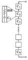
- 1 is a diagram illustrating a circuit in which a plurality of capacitors are connected in series and an equivalent circuit of one capacitor.
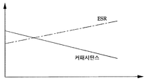
- 2A is a graph illustrating changes in capacitance and ESR (Equivalent Series Resistor) according to deterioration.
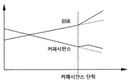
- 2B is a graph showing a change in capacitance and ESR due to a short circuit in the capacitor.
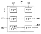
- FIG. 3 is a block diagram schematically illustrating a capacitor failure detection apparatus 100 according to an exemplary embodiment of the present invention.
- FIG. 4 is a flowchart illustrating a method for detecting a capacitor abnormality according to an embodiment of the present invention.
- measurement unit 120 storage unit
- Capacitor elements such as batteries actually include an internal resistance (ESR), which is shown in FIG.
- the total capacitance C tot of a circuit in which a plurality of capacitors are connected in series decreases as the number of capacitors connected in series increases, and is represented by the following equation.
- Equation 1 may be modified as follows.
- Equation 2 C 0 is the average capacitance of the unit capacitor, N is the number of capacitors connected in series.
- the capacitance C tot_short of the entire circuit increases. This may be expressed as the following equation, where M represents the number of capacitors in which an error has occurred.
- Equation 3 the number (M) of capacitors in which an abnormality occurs may be estimated from Equation 3, which may be expressed by the following equation.
- the capacitance of the entire circuit increases, the number of capacitors N of the entire circuit, and the average capacitance C 0 of the unit capacitors.
- the value of the capacitance (C tot_short ) of the entire circuit in the case of an abnormality in the capacitor is known, it is conceived that the number (M) of the capacitor having an abnormality can be estimated.
- FIG. 2A shows the change in total capacitance and ESR (Equivalent Series Resistor) due to deterioration
- FIG. 2B shows the change in total capacitance and ESR due to a short circuit of some capacitors.
- ESR Equivalent Series Resistor
- the capacitor abnormality detecting apparatus 100 includes a measuring unit 110, a memory unit 120, a calculating unit 130, a determining unit 140, an abnormal number estimating unit 150, and a notification unit 160. Include.
- the measuring unit 110 is configured to measure the capacitance of the entire circuit from both ends of the circuit in which two or more capacitors are connected in series.
- the capacitance of the circuit can be obtained by measuring the rate of change of the voltage over time while passing a constant current by the measuring unit 110.
- the method of measuring capacitance is not limited to this, and any conventional method for measuring the capacitance of a circuit can be used.
- the storage unit 120 is configured to store the capacitance of the circuit measured by the measuring unit 110 and the circuit use time (charge and discharge time) at the time of measurement.
- the storage unit 120 may be any medium as long as it can store data, and is not limited to a specific storage medium.
- the calculator 130 is configured to calculate a reduction rate of the capacitance according to the circuit usage time based on the capacitance data of the circuit and the circuit usage time data stored according to the plurality of measurements.
- the determination unit 140 is configured to determine whether an abnormality has occurred in at least one capacitor constituting the circuit. For example, the determination unit 140 determines whether the capacitance of the measured circuit is out of a predetermined range from the expected capacitance according to the calculated reduction rate, or the capacitance of the measured circuit is measured immediately before and stored in the By determining whether the capacitance is greater than a predetermined value or not, it is possible to determine whether an individual capacitor constituting the circuit is abnormal.
- the error number estimator 150 calculates the average capacitance of the unit capacitors constituting the circuit based on the expected capacitance according to the calculated reduction rate, calculates the average capacitance, the number of capacitors constituting the circuit, and the measured capacitance of the circuit. It is configured to estimate the number of the capacitor having a fault according to the above [Equation 4] based on.
- the notification unit 160 determines that the abnormality of the capacitor is determined by the determination unit 140 or when the number of capacitors in which the abnormality is estimated by the abnormality number estimating unit 150 is estimated, the abnormality or abnormality of the capacitor is determined. And inform the user or the like of the number of capacitors that have occurred. For example, a screen display method or a sound method may be used as the notification method, and a signal indicating an abnormal occurrence of a capacitor or the number of capacitors having an abnormality may be transmitted to an external device.
- the total capacitance of the circuit is measured from both ends of the circuit (S110), and the measured capacitor and the circuit use time (charge / discharge time) at the time of measurement are stored in the storage unit (S120).
- the reduction ratio of the capacitance according to the circuit usage time is calculated based on the capacitance data of the circuit and the circuit usage time data stored in accordance with a plurality of measurements (S130), and it is determined whether an abnormality has occurred in at least one capacitor constituting the circuit. (S140). For example, whether an abnormality has occurred in the capacitor determines whether or not the capacitance of the measured circuit is out of a predetermined range from the expected capacitance according to the calculated reduction rate, or the capacitance of the measured circuit is measured and stored immediately before it. The determination can be made by determining whether or not the capacitance is greater than a predetermined value.
- the average capacitance of the unit capacitor constituting the circuit is calculated based on the expected capacitance according to the calculated reduction rate, and the calculated average capacitance, constituting the circuit, Based on the number of capacitors and the measured capacitance of the circuit, the number of abnormal capacitors is estimated according to [Equation 4] (S150). Thereafter, an error occurs in the capacitor and how many capacitors the user is notified of (S160).
- the fault of the individual capacitors can be accurately detected at low cost in a circuit in which two or more capacitors are connected in series, and the number of individual capacitors in which the fault has occurred can also be predicted.
Landscapes
- Physics & Mathematics (AREA)
- General Physics & Mathematics (AREA)
- Engineering & Computer Science (AREA)
- Power Engineering (AREA)
- Measurement Of Resistance Or Impedance (AREA)
- Testing Electric Properties And Detecting Electric Faults (AREA)
- Testing Of Short-Circuits, Discontinuities, Leakage, Or Incorrect Line Connections (AREA)
Abstract
Description


Claims (8)
- 2 이상의 커패시터가 직렬로 연결된 회로에서 커패시터의 이상을 검출하는 방법으로서,상기 회로의 양단으로부터 상기 회로의 커패시턴스를 측정하는 측정 단계와,측정된 상기 회로의 커패시턴스 및 측정시의 회로 사용 시간을 기억부에 저장하는 저장 단계와,복수회의 측정에 따라 저장된 상기 회로의 커패시턴스 데이터 및 상기 회로 사용 시간 데이터에 기초하여 회로 사용 시간에 따른 커패시턴스의 감소율을 산출하는 산출 단계와,측정된 상기 회로의 커패시턴스와, 상기 산출된 감소율에 따라 예상되는 커패시턴스를 비교하여, 상기 회로를 구성하는 적어도 1개의 커패시터에 이상이 생겼는지를 판정하는 판정 단계를 포함하는 커패시터 이상 검출 방법.
- 제1항에 있어서,상기 판정 단계에서는, 측정된 상기 회로의 커패시턴스가 상기 산출된 감소율에 따라 예상되는 커패시턴스로부터 미리 결정된 범위를 벗어나는 경우에, 커패시터에 이상이 생겼다고 판정하는 것인 커패시터 이상 검출 방법.
- 제1항에 있어서,상기 산출된 감소율에 따라 예상되는 커패시턴스에 기초하여 상기 회로를 구성하는 단위 커패시터의 평균 커패시턴스를 계산하고, 계산된 평균 커패시턴스, 상기 회로를 구성하는 커패시터의 개수 및 측정된 상기 회로의 커패시턴스에 기초하여 이상이 생긴 커패시터의 개수를 추정하는 이상 개수 추정 단계를 더 포함하는 커패시터 이상 검출 방법.
- 2 이상의 커패시터가 직렬로 연결된 회로에서 커패시터의 이상을 검출하는 방법으로서,상기 회로의 양단으로부터 상기 회로의 커패시턴스를 측정하는 측정 단계와,복수회의 측정에 따른 상기 회로의 커패시턴스 및 측정시의 회로 사용 시간을 기억부에 저장하는 저장 단계와,측정된 상기 회로의 커패시턴스가 그 직전에 측정되어 저장된 상기 회로의 커패시턴스보다 미리 결정된 값 보다 큰지 여부를 판정하고, 크다고 판정된 경우에, 상기 회로를 구성하는 적어도 1개의 커패시터에 이상이 생겼다고 판정하는 판정 단계를 포함하는 커패시터 이상 검출 방법.
- 2 이상의 커패시터가 직렬로 연결된 회로에서 커패시터의 이상을 검출하는 장치로서,상기 회로의 양단으로부터 상기 회로의 커패시턴스를 측정하는 측정부와,측정된 상기 회로의 커패시턴스 및 측정시의 회로 사용 시간을 저장하는 기억부와,측정된 상기 회로의 커패시턴스와, 기 설정된 예상 커패시턴스를 비교하여, 상기 회로를 구성하는 적어도 1개의 커패시터에 이상이 생겼는지를 판정하는 판정부,를 포함하는 커패시터 이상 검출 장치.
- 제5항에 있어서,상기 기 설정된 예상 캐패시턴스는 상기 커패시턴스의 측정 직전에 측정되어 저장되었던 상기 회로의 커패시턴스이며,상기 판정부는 상기 측정된 상기 회로의 커패시턴스가 상기 직전에 측정되어 저장되었던 상기 회로의 커패시턴스 보다 미리 결정된 값보다 큰지 여부를 판정하여 상기 적어도 1개의 커패시터에 이상이 생겼다고 판정하는 것을 특징으로 하는 커패시터 이상 검출 장치.
- 제5항에 있어서,복수회의 측정에 따라 저장된 상기 회로의 커패시턴스 데이터 및 상기 회로 사용 시간 데이터에 기초하여 회로 사용 시간에 따른 커패시턴스의 감소율을 산출하는 산출부를 더 포함하며,상기 판정부는 상기 측정된 상기 회로의 커패시턴스와 상기 예상 커패시턴스를 비교하는 것을 특징으로 하는 커패시터 이상 검출 장치.
- 제6항에 있어서,복수회의 측정에 따라 저장된 상기 회로의 커패시턴스 데이터 및 상기 회로 사용 시간 데이터에 기초하여 회로 사용 시간에 따른 커패시턴스의 감소율을 산출하는 산출부와,상기 산출된 감소율에 따라 예상되는 커패시턴스에 기초하여 상기 회로를 구성하는 단위 커패시터의 평균 커패시턴스를 계산하고, 계산된 평균 커패시턴스, 상기 회로를 구성하는 커패시터의 개수 및 측정된 상기 회로의 커패시턴스에 기초하여 이상이 생긴 커패시터의 개수를 추정하는 이상 개수 추정부를 더 포함하는 커패시터 이상 검출 장치.
Priority Applications (2)
| Application Number | Priority Date | Filing Date | Title |
|---|---|---|---|
| US13/993,571 US20130268217A1 (en) | 2010-12-14 | 2011-12-13 | Method and apparatus for detecting abnormality of a capacitor |
| CN201180060158.2A CN103261901B (zh) | 2010-12-14 | 2011-12-13 | 电容器的异常检测方法及异常检测装置 |
Applications Claiming Priority (2)
| Application Number | Priority Date | Filing Date | Title |
|---|---|---|---|
| KR10-2010-0127729 | 2010-12-14 | ||
| KR1020100127729A KR101788866B1 (ko) | 2010-12-14 | 2010-12-14 | 커패시터의 이상 검출 방법 및 이상 검출 장치 |
Publications (1)
| Publication Number | Publication Date |
|---|---|
| WO2012081892A1 true WO2012081892A1 (ko) | 2012-06-21 |
Family
ID=46244903
Family Applications (1)
| Application Number | Title | Priority Date | Filing Date |
|---|---|---|---|
| PCT/KR2011/009593 Ceased WO2012081892A1 (ko) | 2010-12-14 | 2011-12-13 | 커패시터의 이상 검출 방법 및 이상 검출 장치 |
Country Status (4)
| Country | Link |
|---|---|
| US (1) | US20130268217A1 (ko) |
| KR (1) | KR101788866B1 (ko) |
| CN (1) | CN103261901B (ko) |
| WO (1) | WO2012081892A1 (ko) |
Cited By (2)
| Publication number | Priority date | Publication date | Assignee | Title |
|---|---|---|---|---|
| US20200241060A1 (en) * | 2019-01-28 | 2020-07-30 | Gentec Inc. | Method and apparatus for monitoring capacitor faults in a capacitor bank |
| US12490754B2 (en) | 2014-11-14 | 2025-12-09 | Arla Foods Amba | Whey protein-based, high protein, yoghurt-like product, ingredient suitable for its production, and method of production |
Families Citing this family (6)
| Publication number | Priority date | Publication date | Assignee | Title |
|---|---|---|---|---|
| US9678132B2 (en) * | 2014-08-29 | 2017-06-13 | Texas Instruments Incorporated | Capacitor combination stress testing |
| CN105021932B (zh) * | 2015-08-17 | 2017-10-20 | 新誉轨道交通科技有限公司 | 一种电容异常检测系统及其工作方法 |
| KR102401578B1 (ko) | 2015-09-03 | 2022-05-24 | 삼성전자주식회사 | 보조 전원 검사 방법 및 이를 적용한 전자 장치 |
| US10914790B2 (en) * | 2018-01-26 | 2021-02-09 | Hewlett Packard Enterprise Development Lp | Performance tests of capacitors |
| US11448680B2 (en) * | 2020-03-31 | 2022-09-20 | KYOCERA AVX Components Corporation | Screening method for electrolytic capacitors that maintains individual capacitor unit identity |
| CN112858792B (zh) * | 2021-01-15 | 2024-07-09 | 胜达克半导体科技(上海)股份有限公司 | 一种基于测试载具板的蓄能电容失效检测方法 |
Citations (3)
| Publication number | Priority date | Publication date | Assignee | Title |
|---|---|---|---|---|
| KR20020006984A (ko) * | 2000-07-14 | 2002-01-26 | 권순형 | 정전 용량 변화를 이용한 감지 회로 |
| KR20020071610A (ko) * | 2001-03-07 | 2002-09-13 | 엘지산전 주식회사 | 인버터의 직류 커패시터 노화 감시 방법 |
| KR20090084854A (ko) * | 2006-10-06 | 2009-08-05 | 에네르델, 인코포레이티드 | 직렬 연결 셀 전압을 측정하는 시스템과 방법 |
Family Cites Families (4)
| Publication number | Priority date | Publication date | Assignee | Title |
|---|---|---|---|---|
| JPH02300670A (ja) * | 1989-05-16 | 1990-12-12 | Mitsubishi Electric Corp | インダクタス測定装置 |
| US20070115006A1 (en) * | 2005-11-22 | 2007-05-24 | Maxwell Technologies, Inc. | Capacitor screening |
| CN101313380A (zh) * | 2005-11-22 | 2008-11-26 | 麦斯韦尔技术股份有限公司 | 电容器的筛选 |
| DE102006019187A1 (de) * | 2006-04-21 | 2007-10-31 | Huf Hülsbeck & Fürst Gmbh & Co. Kg | Verfahren und Schaltungsanordnung zum Messen einer Kapazität |
-
2010
- 2010-12-14 KR KR1020100127729A patent/KR101788866B1/ko not_active Expired - Fee Related
-
2011
- 2011-12-13 CN CN201180060158.2A patent/CN103261901B/zh not_active Expired - Fee Related
- 2011-12-13 US US13/993,571 patent/US20130268217A1/en not_active Abandoned
- 2011-12-13 WO PCT/KR2011/009593 patent/WO2012081892A1/ko not_active Ceased
Patent Citations (3)
| Publication number | Priority date | Publication date | Assignee | Title |
|---|---|---|---|---|
| KR20020006984A (ko) * | 2000-07-14 | 2002-01-26 | 권순형 | 정전 용량 변화를 이용한 감지 회로 |
| KR20020071610A (ko) * | 2001-03-07 | 2002-09-13 | 엘지산전 주식회사 | 인버터의 직류 커패시터 노화 감시 방법 |
| KR20090084854A (ko) * | 2006-10-06 | 2009-08-05 | 에네르델, 인코포레이티드 | 직렬 연결 셀 전압을 측정하는 시스템과 방법 |
Cited By (3)
| Publication number | Priority date | Publication date | Assignee | Title |
|---|---|---|---|---|
| US12490754B2 (en) | 2014-11-14 | 2025-12-09 | Arla Foods Amba | Whey protein-based, high protein, yoghurt-like product, ingredient suitable for its production, and method of production |
| US20200241060A1 (en) * | 2019-01-28 | 2020-07-30 | Gentec Inc. | Method and apparatus for monitoring capacitor faults in a capacitor bank |
| US11525850B2 (en) * | 2019-01-28 | 2022-12-13 | Gentec Inc. | Method and apparatus for monitoring capacitor faults in a capacitor bank |
Also Published As
| Publication number | Publication date |
|---|---|
| US20130268217A1 (en) | 2013-10-10 |
| KR20120066400A (ko) | 2012-06-22 |
| CN103261901B (zh) | 2016-02-17 |
| KR101788866B1 (ko) | 2017-11-16 |
| CN103261901A (zh) | 2013-08-21 |
Similar Documents
| Publication | Publication Date | Title |
|---|---|---|
| WO2012081892A1 (ko) | 커패시터의 이상 검출 방법 및 이상 검출 장치 | |
| CN112415401B (zh) | 应用于车辆的电池监控方法、装置和设备 | |
| US11038356B2 (en) | Open cell detection method and open cell recovery detection method in a battery management system | |
| WO2019074254A1 (ko) | 컨택터 코일 전류를 이용한 컨택터 수명 진단 시스템 및 방법 | |
| EP3676625A1 (en) | Apparatus and methods for identifying anomaly(ies) in re-chargeable battery of equipment and connected component(s) | |
| EP2559135A2 (en) | Battery management system and method for transferring data within the battery management system | |
| CN207662966U (zh) | 电池包绝缘电阻检测电路、电池管理系统及电动汽车 | |
| WO2017160035A1 (ko) | 전지모듈의 개방 회로 결함 상태를 결정하는 전지 시스템 및 방법 | |
| KR102436468B1 (ko) | 배터리 전원 설비 진단 hmi 시스템 | |
| WO2020226308A1 (ko) | 배터리셀 진단 장치 및 방법 | |
| WO2024058428A1 (ko) | 배터리 셀 퇴화도 진단 방법 및 이를 이용하는 배터리 시스템 | |
| KR101955537B1 (ko) | 에너지저장시스템의 지락 감지 장치 및 방법 | |
| US11637443B2 (en) | Backup power supply for electronic system and operation method thereof | |
| KR20210011235A (ko) | 배터리 셀 진단 장치 및 방법 | |
| WO2022075655A1 (en) | Methods and systems for detecting faulty behavior in a battery | |
| CN112213675B (zh) | 一种电流传感器故障判别方法及装置 | |
| JP7225897B2 (ja) | 電池監視システム | |
| KR20180103210A (ko) | 배터리 모듈 통신 장치 및 그 방법 | |
| CN112622664B (zh) | 充电桩桩内温度检测系统和方法 | |
| KR102431550B1 (ko) | 복수의 배터리 셀과 배터리 관리 시스템의 접속 장치 | |
| EP4553519A1 (en) | Detection and warning of thermal runaway in electrical energy storage systems | |
| CN118033520B (zh) | 超导传感器精度检测装置、方法及系统 | |
| KR102950388B1 (ko) | 에너지 저장 시스템의 dc 버스바 고장 감지 방법 및 장치 | |
| CN105116272A (zh) | 一种检测电能表二次回路接线故障的装置及方法 | |
| EP4535506A1 (en) | Battery pack for preventing overheating misdiagnosis due to environmental temperature and method for preventing misdiagnosis |
Legal Events
| Date | Code | Title | Description |
|---|---|---|---|
| WWE | Wipo information: entry into national phase |
Ref document number: 201180060158.2 Country of ref document: CN |
|
| 121 | Ep: the epo has been informed by wipo that ep was designated in this application |
Ref document number: 11848207 Country of ref document: EP Kind code of ref document: A1 |
|
| WWE | Wipo information: entry into national phase |
Ref document number: 13993571 Country of ref document: US |
|
| NENP | Non-entry into the national phase |
Ref country code: DE |
|
| 122 | Ep: pct application non-entry in european phase |
Ref document number: 11848207 Country of ref document: EP Kind code of ref document: A1 |