WO2012081826A1 - 이온 싸이클로트론 공명 질량 분석기 신호성능 향상 제어장치 - Google Patents
이온 싸이클로트론 공명 질량 분석기 신호성능 향상 제어장치 Download PDFInfo
- Publication number
- WO2012081826A1 WO2012081826A1 PCT/KR2011/008231 KR2011008231W WO2012081826A1 WO 2012081826 A1 WO2012081826 A1 WO 2012081826A1 KR 2011008231 W KR2011008231 W KR 2011008231W WO 2012081826 A1 WO2012081826 A1 WO 2012081826A1
- Authority
- WO
- WIPO (PCT)
- Prior art keywords
- signal
- ion
- control
- excitation
- detection
- Prior art date
- Legal status (The legal status is an assumption and is not a legal conclusion. Google has not performed a legal analysis and makes no representation as to the accuracy of the status listed.)
- Ceased
Links
Images
Classifications
-
- H—ELECTRICITY
- H01—ELECTRIC ELEMENTS
- H01J—ELECTRIC DISCHARGE TUBES OR DISCHARGE LAMPS
- H01J49/00—Particle spectrometers or separator tubes
- H01J49/02—Details
-
- H—ELECTRICITY
- H01—ELECTRIC ELEMENTS
- H01J—ELECTRIC DISCHARGE TUBES OR DISCHARGE LAMPS
- H01J49/00—Particle spectrometers or separator tubes
- H01J49/02—Details
- H01J49/022—Circuit arrangements, e.g. for generating deviation currents or voltages ; Components associated with high voltage supply
-
- H—ELECTRICITY
- H01—ELECTRIC ELEMENTS
- H01J—ELECTRIC DISCHARGE TUBES OR DISCHARGE LAMPS
- H01J49/00—Particle spectrometers or separator tubes
- H01J49/26—Mass spectrometers or separator tubes
- H01J49/34—Dynamic spectrometers
- H01J49/36—Radio frequency spectrometers, e.g. Bennett-type spectrometers, Redhead-type spectrometers
- H01J49/38—Omegatrons ; using ion cyclotron resonance
Definitions
- the present invention relates to an ion trap control apparatus and method of an ion cyclotron resonance mass spectrometer, and more particularly, to ion position for extending ion survival time for signal detection of ions injected into an ion trap portion of an ion cyclotron resonance mass spectrometer.
- the present invention relates to a trap voltage control device and a method for optimizing adjustment and ion motion.
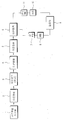
- a typical ion cyclotron resonance mass spectrometer includes a sample injection ionizer 1 for ionizing and releasing an injected sample, and a first ion for transmitting ions emitted from the sample injection ionizer 1.
- the ion selector / separator 3 which selects or separates ions transmitted through the transmitter 2, the first ion transporter 2 according to a specific purpose
- An ion collision part 4 for discharging the ion selected or separated by collision with a collision gas into a smaller size, and a second ion transmission part 5 for transmitting ions divided by the ion collision part 4,
- the ion trap 6 to collect the ions transmitted through the second ion transfer unit 5 to the ion trap and then detect an electrical signal representing the mass of the ion corresponding to a specific purpose
- the high frequency signal amplified by the high frequency amplifier 7 is applied to the ion trap 6 to excite the ions.
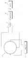
- FIG. 2 is a circuit diagram of ion traps and signal transfer, wherein the excited signal passes through another electrode of the ion trap and passes through the preamplifier 11 shown in FIG.
- the signal is amplified and passed through the digitizer (A / D) 10 to become a digital signal, and the computer 9 performs signal processing.
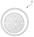
- the ions implanted in the ion trap 6 according to the prior art have a circular motion by the signal applied in the form of FIG. 3, where the circular motion forms a symmetrical structure at the center of the trap, and thus the fidelity of the signal is improved. good.
- the present invention is to solve the above-mentioned conventional problems, and applies an electrical signal to the trap electrode to ensure that the ions injected into the ion trap of the ion cyclotron resonance mass spectrometer as close as possible to the center of the trap, the injected ions It is an object of the present invention to provide an ion cyclotron resonance mass spectrometer that improves the fidelity of an ion signal and an apparatus and method for improving signal performance by adjusting the signal of a trap electrode for ion movement to adjust deflected ion motion.
- the ion cyclotron resonance mass spectrometer improves the signal performance of the first and second excitation electrodes 1 by a control program of the computer 9 so that the ions injected into the ion trap 6 move.
- (1-2) Ion which inputs a high frequency signal and adjusts the position of the ion by applying a control signal to the first and second detection electrodes 2-1 and 2-2 for ion signal detection.
- a high frequency signal or a control signal from the high frequency amplifier (7) is selected for ion movement to the first and second excitation electrodes (1-1) (1-2).
- Excitation electrode control means for applying; Arbitrary waveforms generated from the first and second control signal generators 21 and 23 for generating control signals for ion movement to the first and second detection electrodes 2-1 and 2-2.
- Detection electrode control means for applying each of the detection electrodes 2-1 and 2-2 to each other;
- Detection electrode signal processing means for detecting an ion signal from said first and second detection electrodes (2-1) (2-2) and converting it into an amplification and a digital signal;
- an excitation electrode signal processing means for detecting an ion signal from the first and second excitation electrodes 1-1 and 1-2 and amplifying and converting the digital signal into a digital signal by selection of the third excitation switching unit 15. It characterized by comprising;
- the excitation electrode control means generates third and fourth control signal generators for generating an arbitrary waveform and supplying the first and second excitation electrodes 1-1 and 1-2 by a control program of the computer.
- a third excitation switching unit 15 for applying the signals output from the first and second excitation switching units 12 and 14 to the first and second excitation electrodes 1-1 and 1-2, respectively. It consists of
- the detection electrode control means transmits each control signal generated from the first and second control signal generators 21 and 23 to the first and second detection electrodes 2-1 and 2-2.
- First and second detection switching units 22 which apply or detect an ion signal from the first and second detection electrodes 2-1 and 2-2 and select an output to the detection electrode signal processing means. 24;
- the detection electrode signal processing means is amplified from the second preamplifier 25 and the second preamplifier 25 to amplify the ion signals output from the first and second detection switching units 22 and 24.
- a digitizer 26 for converting an ion signal into a digital signal and outputting the digital signal to the computer 9.
- the excitation electrode signal processing means detects and amplifies an ion signal from the first and second excitation electrodes 1-1 (1-2) by the selection of the third excitation switching unit 15. And a first digitizer 17 for converting the ion signal amplified by the first preamplifier 16 into a digital signal and outputting the digital signal to the computer 9.
- the ion cyclotron resonance mass spectrometer improves the signal performance of the first and second excitation electrodes 1 by a control program of the computer 9 so that the ions injected into the ion trap 6 move.
- -1) inputs a high frequency signal to (1-2), and adjusts the position of the ion by applying a control signal to the first and second detection electrodes 2-1 and 2-2 for ion signal detection.
- a control signal generated by the first to fourth control signal generators driven by the control of the computer when an ion is injected into the ion trap is the first and second.
- Ion position adjusting process is applied to the detection electrodes (2-1) (2-2) and the first and second excitation electrodes (1-1) (1-2) to adjust the position of the ions in the ion trap to the center ; Applying a high frequency signal to the first and second excitation electrodes 1-1 and 1-2; And an ion signal detection process for detecting ion signals from the first and second detection electrodes 2-1 and 2-2.
- a high frequency signal is applied to the first and second excitation electrodes 1-1 and 1-2, and then the first and second detection electrodes 2-1 and 2-2 are applied. It further comprises a secondary ion position adjustment process for adjusting the position of the ions by simultaneously applying the control signals from the first and second control signal generator 21, 22 to the.
- the ion cyclotron resonance mass spectrometer improves the signal performance of the first and second excitation electrodes 1 by a control program of the computer 9 so that the ions injected into the ion trap 6 move.
- -1) inputs a high frequency signal to (1-2), and adjusts the position of the ion by applying a control signal to the first and second detection electrodes 2-1 and 2-2 for ion signal detection.
- a control signal generated by the first to fourth control signal generators driven by the control of the computer when an ion is injected into the ion trap is the first and second.
- Ion position adjusting process is applied to the detection electrodes (2-1) (2-2) and the first and second excitation electrodes (1-1) (1-2) to adjust the position of the ions in the ion trap to the center ; Applying a high frequency signal to the first and second excitation electrodes 1-1 and 1-2; And an ion signal detection process for detecting ion signals from the first and second detection electrodes 2-1 and 2-2.
- the ion cyclotron resonance mass spectrometer signal performance improvement control device has an effect that can be adjusted to be located in the center of the trap when there is a deflection of the injected ions, so that the deflection can be adjusted even when supplying a voltage for ion movement
- the survival time in the trap of the ions can be extended, and the ion movement can be made smoothly, thereby improving the signal sensitivity.
- FIG. 1 is a block diagram of a typical ion cyclotron resonance mass spectrometer
- FIG. 2 is a block diagram of the ion trap and the signal transmission device of the ion cyclotron resonance mass spectrometer according to the prior art
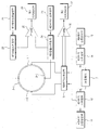
- FIG. 4 is a block diagram of an apparatus for improving signal performance of an ion cyclotron resonance mass spectrometer according to an exemplary embodiment of the present invention.
- FIG. 5 is a block diagram of an apparatus for improving signal performance of an ion cyclotron resonance mass spectrometer according to another exemplary embodiment of the present invention.
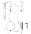
- FIG. 4 is a block diagram of an apparatus for improving the signal performance of an ion cyclotron resonance mass spectrometer according to an exemplary embodiment of the present invention, in which ion implanted ions are ion ionized by a control signal and a high frequency signal applied by a control program of the computer 10.
- the ion trap 6 including the first and second excitation electrodes 1-1 (1-2) and the first and second detection electrodes 2-1 and 2-2, and the computer 9
- the third and fourth control signal generators 11 and 13 for generating arbitrary waveforms and supplying them to the first and second excitation electrodes 1-1 and 1-2
- a first excitation switching unit 12 for selectively outputting a high frequency signal generated by the amplifier 7 or a control signal from the third control signal generator 11 by the computer control program, and the high frequency amplifier 7
- a second filter for selectively outputting the high frequency signal from the control signal or the control signal from the fourth control signal generator 13 by the computer control program.
- the first and second excitation electrodes (1-1) (1-2) for applying the signals output from the switching unit 14 and the first and second excitation switching unit (12) (14), respectively The first excitation and detection of the ion signal from the first and second excitation electrodes (1-1) (1-2) by selecting the excitation switching unit 15 and the third excitation switching unit (15)
- a first digitizer 17 for converting the preamplifier 16, the ion signal amplified by the first preamplifier 16 into a digital signal, and outputting the digital signal to the computer 9; and first and second control signals.
- Each control signal generated from the generators 21 and 23 is applied to the first and second detection electrodes 2-1 and 2-2, or the first and second detection electrodes 2-1.
- Ion signals detected from the first and second detection switching units 22 and 24 for selecting detection of the ion signal from (2-2) and the first and second detection switching units 22 and 24. Converts the ion signal amplified from the second preamplifier 25 and the second preamplifier 25 into a digital signal. And a digitizer 26 for outputting to the computer 9.
- each electrode (2_1) by the control signal applied from the first to fourth control signal generator 21, 23, 11, 13 when ion implantation into the ion trap (6)
- a signal is applied to (2_2) (1_2) (1_1) to adjust the position of the ions, and then the high frequency signal is applied to the first and second excitation electrodes (1-1) (1-2).
- each electrode (2_1) (2_2) (1_2) by the control signal applied from the first to fourth control signal generator (21) (23) (11) 13 during ion implantation into the ion trap (6) 1_1 is applied to adjust the position of the ions, and then a high frequency signal (a signal including a DC offset) is applied to the first and second excitation electrodes 1-1 and 1-2.
- Each control signal is simultaneously applied to the first and second detection electrodes 2-1 and 2-2 to adjust the position of the ions, and then the first and second detection electrodes 2-1 and 2-2.
- a high frequency signal (a signal including a DC offset) is applied to the first and second excitation electrodes 1-1 and 1-2.
- Each control signal is simultaneously applied to the second detection electrodes 2-1 and 2-2 to adjust the position of the ions, and then the ion signals at the first and second detection electrodes 2-1 and 2-2. There is a way to detect.
- the computer 9 uses the control program to control the first and second control signal generators 21 and 23, the second and fourth control signal generators 11 and 13, and the selective switching unit 12 ( 14, 15, 22, and 24, respectively, in driving control, the first and second excitation electrodes 1-1 (1) (in order to adjust the position of ions entering and moving in the ion trap 6 to the center).
- a control signal is applied to the 1-2 and the first and second detection electrodes 2-1 and 2-2, respectively.
- a control signal should be applied to each of the four electrodes 1-1 (1-2) (2-1) and 2-2 in order to adjust the position of the ions entering the ion trap 6.
- control signals generated by the first to fourth control signal generators 21, 23, 11, and 13 are each electrode 1-1 (1-2) (2-1) according to the deflection of ions.
- (2-2) is a magnitude of a DC voltage or a square wave lasting for a predetermined time, and a high frequency signal is mainly used as a scanned sine wave having a start frequency and an end frequency.
- control signal of the fourth control signal generator 13 is applied to the first excitation electrode 1-1 by selection of the second and third excitation switching units 14 and 15.
- control signal of the third control signal generator 11 is applied to the excitation electrode 1-2 by selection of the first and third excitation switching units 12 and 15.
- the first detection electrode (2-1) is applied to the control signal of the first control signal generator 21 through the first detection switching unit 22, the second detection electrode (2-2) The control signal of the second control signal generator 23 is applied through the second detection switching unit 24.
- a high frequency signal is applied to the ions entering the ion trap 6 to detect an ion signal.
- the first and second excitation switching units output two high frequency signals having a phase difference of 180 degrees from the high frequency amplifier 7. It is applied to the first and second excitation electrodes (1-1) (1-2) through (12) and (14), respectively.
- the DC offset voltage may be applied to the high frequency signals applied to the first and second excitation electrodes 1-1 and 1-2. That is, the first and second detection electrodes 2-1 and 2-2 in the ion trap 6 are applied with a high frequency signal to the first and second excitation electrodes 1-1 and 1-2. At the same time the necessary control signal is applied.
- the control signal is generated by the first control signal generator 21 and applied to the first detection electrode 2-1 by selection of the first detection switch 22, and the second control signal generator 23.
- the control signal generated at is applied to the second detection electrode 24 by the selection of the second detection switching unit 24.
- the first detection electrode 2-1 is connected to the first detection switching unit.
- Input to one terminal of the preamplifier 25 by selection of (22) the second detection electrode (2-2) is different from the preamplifier 25 by the selection of the second detection switching unit (24)
- the signal amplified is input to one terminal, and the signal amplified is converted into a digital signal through the first digitizer 26 and then transmitted to the computer 9.
- the second preamplifier may be configured by selecting the third excitation switching unit 15 from the signals from the first and second excitation electrodes 1-1 and 1-2.
- the signal is amplified by two terminals (16), converted into a digital signal through the second digitizer (17), and transmitted to the computer (9).
- FIG. 5 is a block diagram of an apparatus for improving signal performance of an ion cyclotron resonance mass spectrometer according to another embodiment of the present invention.
- the ion trap 6 may be applied without a procedure of applying a high frequency signal after applying a control signal.
- the control signal is applied to the first and second detection electrodes 2-1 and 2-2 while applying a high frequency signal to the ions implanted in the ion.
- the high frequency signal amplified by the high frequency amplifier 7 is applied to the first and second excitation electrodes 1-1 and 1-2 through the third excitation switching unit 15, and at the same time, the first and second The control signals generated by the control signal generators 21 and 23 are transferred to the first and second detection electrodes 2-1 through the first and second detection switching units 22 and 24. Since each is applied to 2), the position of the ions is adjusted.
- the high frequency signal applied to the first and second excitation electrodes (1-1) (1-2) includes a DC offset.
- ion signals are detected from the first and second detection electrodes 2-1 and 2-2 and the first preamplifier 25 is formed through the first and second detection switching units 22 and 24. Amplified and amplified and input to the first digitizer 26.
- an ion signal detected by the third excitation switching unit 15 from the first and second excitation electrodes 1-1 and 1-2 is transferred through the second preamplifier 16. Signal amplification is made and the amplified ion signal is transmitted to the computer 9.
Landscapes
- Chemical & Material Sciences (AREA)
- Analytical Chemistry (AREA)
- Other Investigation Or Analysis Of Materials By Electrical Means (AREA)
- Electron Tubes For Measurement (AREA)
Abstract
본 발명은 이온 싸이클로트론 공명 질량 분석기 신호성능 향상 제어장치 및 방법에 관한 것으로, 이온 싸이클로트론 공명 질량 분석기의 이온 트랩에 주입되는 이온이 트랩의 중심으로 최대한 가깝게 주입되게 하기 위한 전기적 신호를 트랩 전극에 인가하며, 주입된 이온이 이온 운동을 하기 위한 트랩 전극의 신호를 적절히 조정하여 편향된 이온 운동을 조절하도록 하므로, 이온 신호의 충실성을 향상시킬 수 있다. 본 발명은 이온 싸이클로트론 공명 질량 분석기의 신호성능 향상 제어방법에 있어서, 이온위치조정과정, 이온신호검출과정을 포함하여 이루어진다.
Description
본 발명은 이온 싸이클로트론 공명 질량 분석기의 이온 트랩 제어 장치 및 그 방법에 관한 것이며, 더욱 상세히는 이온 싸이클로트론 공명 질량 분석기의 이온트랩부에 주입된 이온의 신호 검출을 위한 이온 생존 시간을 연장시키기 위한 이온 위치 조정과 이온 운동을 최적화 하는 트랩 전압 제어 장치와 그 방법에 관한 것이다.
일반적인 이온 싸이클로트론 공명 질량 분석기의 제어장치에 대하여 첨부된 도 1, 도 2을 참고하여 상세히 설명하면 다음과 같다.
일반적인 이온 싸이클로트론 공명 질량 분석기는 도 1에 도시된 바와 같이, 주입된 시료를 이온화시켜 방출하는 시료주입 이온화부(1)와, 상기 시료주입 이온화부(1)로부터 방출된 이온을 전송하는 제1이온전송부(2), 상기 제1이온전송부(2)를 통해 전송된 이온을 특정 목적에 따라 선택하거나 분리하여 방출하는 이온선택/분리부(3), 상기 이온선택/분리부(3)에 의해 선택되거나 분리된 이온을 충돌 가스와 충돌시켜 더 작은 크기로 나누어 방출하는 이온충돌부(4), 상기 이온충돌부(4)에 의해 나누어진 이온을 전송하는 제2이온전송부(5), 상기 제2이온전송부(5)를 통해 전송된 이온을 이온 트랩에 수집한 후 특정 목적에 부합하는 이온의 질량을 나타내는 전기적 신호를 검출하는 이온트랩(6), 상기 이온트랩(6)에서의 신호 검출을 위해 컴퓨터(10)의 제어 프로그램에 의하여 임의파형을 발생시키는 임의파형발생부(AWG)(8)와, 상기 임의파형발생부(8)에 의해 발생된 임의 파형을 증폭시키는 고주파증폭기(RF Amp)(7)로 구성되어, 상기 고주파증폭기(7)로부터 증폭된 고주파신호를 이온트랩(6)에 인가하여 이온을 여기 시킨다.
도 2는 이온트랩과 신호전달에 대한 회로 구성도로서, 상기 여기된 신호는 이온트랩의 또 다른 전극을 통하여 도 2에서 나타나는 전치증폭기(Pre Amp)(11)를 통과하여 검출하기 적당한 신호크기로 증폭하여 디지타이저(A/D)(10)를 통과하여 디지털 신호가 되어 컴퓨터(9)에서 신호처리가 이루어진다.
종래 기술에 따른 이온 트랩(6) 내에 주입된 이온은 도 3의 형태로 인가된 신호에 의하여 원운동을 하며, 여기서 원운동의 형태가 트랩의 중심에서 대칭된 구조를 이룰수록 신호의 충실성이 좋다.
그러나, 중심에서 치우친 상태에서 이온 운동이 이루어진다면 신호의 왜곡이 일어난다. 이온 트랩의 중심에서 대칭된 이온 운동을 하려면 주입된 이온이 이온 트랩의 중심으로 주입 되어야 하고, 이온 운동을 위한 트랩 전극의 신호가 적절해야 한다. 적절하지 못한 신호는 트랩 내 이온 운동의 편향을 가져오기 때문에 신호 왜곡이 일어나는 문제점이 있다.
본 발명은 상기한 종래의 문제점을 해결하기 위한 것으로서, 이온 싸이클로트론 공명 질량 분석기의 이온 트랩에 주입되는 이온이 트랩의 중심으로 최대한 가깝게 주입되게 하기 위한 전기적 신호를 트랩 전극에 인가하며, 주입된 이온이 이온 운동을 하기 위한 트랩 전극의 신호를 적절히 조정하여 편향된 이온 운동을 조절하도록 하므로, 이온 신호의 충실성을 향상시키는 이온 싸이클로트론 공명 질량 분석기 신호성능 향상 제어장치 및 방법을 제공하는데 그 목적이 있다.
본 발명의 목적을 달성하기 위한 이온 싸이클로트론 공명 질량 분석기 신호성능 향상 제어장치는 이온트랩(6)에 주입된 이온이 이온 운동 하도록 컴퓨터(9)의 제어프로그램에 의해 제1,제2여기전극(1-1)(1-2) 고주파신호를 입력하고, 이온신호 검출을 위한 제1,제2검출전극(2-1)(2-2)에 제어신호를 인가함에 따라 이온의 위치를 조정하는 이온 싸이클로트론 공명 질량 분석기의 신호성능 향상 제어장치에 있어서, 상기 제1, 제2여기전극(1-1)(1-2)에 이온운동을 위해 고주파증폭기(7)로부터의 고주파신호 또는 제어신호를 선택 인가시키는 여기전극제어수단; 상기 제1, 제2검출전극(2-1)(2-2)에 이온운동을 위한 제어신호를 발생하는 각각의 제1, 제2제어신호발생부(21)(23)로부터 발생된 임의파형을 각 검출전극(2-1)(2-2)에 각각 인가시키는 검출전극제어수단; 상기 제1, 제2검출전극(2-1)(2-2)로부터 이온신호를 검출하여 증폭 및 디지털신호로 변환하는 검출전극신호처리수단; 및 상기 제3여기스위칭부(15)의 선택에 의하여 상기 제1, 제2여기전극(1-1)(1-2)으로부터 이온신호를 검출하여 증폭 및 디지털신호로 변환하는 여기전극신호처리수단;을 포함하여 구성된 것을 특징으로 한다.
여기서, 상기 여기전극제어수단은 상기 컴퓨터의 제어 프로그램에 의해 임의파형을 발생 및 상기 제1, 제2여기전극(1-1)(1-2)에 공급하는 제3, 제4제어신호발생부(11)(13); 상기 고주파증폭기(7)로부터의 고주파신호 또는 제3제어신호발생부(11)로부터의 제어신호를 상기 컴퓨터 제어 프로그램에 의해 선택 출력하는 제1여기스위칭부(12); 상기 고주파증폭기(7)로부터의 고주파신호 또는 제4제어신호발생부(13)로부터의 제어신호를 상기 컴퓨터 제어 프로그램에 의해 선택 출력하는 제2여기스위칭부(14); 및 상기 제1, 제2여기스위칭부(12)(14)로부터 출력된 신호를 상기 제1, 제2여기전극(1-1)(1-2)으로 각각 인가하는 제3여기스위칭부(15)로 구성된다.
또한, 상기 검출전극제어수단은 상기 제1, 제2제어신호발생부(21)(23)로부터 발생된 각 제어신호를 상기 제1, 제2검출전극(2-1)(2-2)에 인가하거나, 상기 제1, 제2검출전극(2-1)(2-2)으로부터 이온신호를 검출하여 상기 검출전극신호처리수단으로의 출력을 선택하는 제1,제2검출스위칭부(22)(24);로 구성된다.
또한, 상기 검출전극신호처리수단은 상기 제1, 제2검출스위칭부(22)(24)로부터 출력된 이온신호를 증폭하는 제2프리앰프(25)와 제2프리앰프(25)로부터 증폭된 이온신호를 디지털신호로 변환하여 상기 컴퓨터(9)로 출력하는 디지타이저(26)를 포함하여 구성된 것을 특징으로 한다.
상기 여기전극신호처리수단은 상기 제3여기스위칭부(15)의 선택에 의하여 상기 제1, 제2여기전극(1-1)(1-2)으로부터 이온신호를 검출하여 증폭하는 제1프리앰프(16)와, 상기 제1프리앰프(16)을 통해 증폭된 이온신호를 디지털신호로 변환하여 상기 컴퓨터(9)로 출력하는 제1디지타이저(17)를 포함하여 구성된 것을 특징으로 한다.
본 발명의 목적을 달성하기 위한 이온 싸이클로트론 공명 질량 분석기 신호성능 향상 제어과정은 이온트랩(6)에 주입된 이온이 이온 운동 하도록 컴퓨터(9)의 제어프로그램에 의해 제1,제2여기전극(1-1)(1-2)에 고주파신호를 입력하고, 이온신호 검출을 위한 제1,제2검출전극(2-1)(2-2)에 제어신호를 인가함에 따라 이온의 위치를 조정하는 이온 싸이클로트론 공명 질량 분석기의 신호성능 향상 제어방법에 있어서, 상기 이온트랩에 이온 주입시 상기 컴퓨터의 제어에 의하여 구동되는 제1 내지 제4제어신호발생부에서 발생된 제어신호가 상기 제1, 제2검출전극(2-1)(2-2) 및 제1, 제2여기전극(1-1)(1-2)에 각각 인가되어 상기 이온트랩 내의 이온의 위치가 중앙으로 조정되는 이온위치조정과정; 상기 제1, 제2여기전극(1-1)(1-2)에 고주파신호를 인가시키는 고주파인가과정; 및 상기 제1, 제2검출전극(2-1)(2-2)으로부터 이온신호를 검출하는 이온신호검출과정;을 포함하여 이루어진 것을 특징으로 한다.
상기 고주파인가과정에 부가하여 상기 제1, 제2여기전극(1-1)(1-2)에 고주파신호를 인가시킨 후 상기 제1, 제2검출전극(2-1)(2-2)에 상기 제1, 제2제어신호발생부(21)(22)로부터의 제어신호를 동시에 인가시켜 이온의 위치를 조정하는 2차이온위치조정과정을 더 포함하여 이루어진 것을 특징으로 한다.
본 발명의 목적을 달성하기 위한 이온 싸이클로트론 공명 질량 분석기 신호성능 향상 제어과정은 이온트랩(6)에 주입된 이온이 이온 운동 하도록 컴퓨터(9)의 제어프로그램에 의해 제1,제2여기전극(1-1)(1-2)에 고주파신호를 입력하고, 이온신호 검출을 위한 제1,제2검출전극(2-1)(2-2)에 제어신호를 인가함에 따라 이온의 위치를 조정하는 이온 싸이클로트론 공명 질량 분석기의 신호성능 향상 제어방법에 있어서, 상기 이온트랩에 이온 주입시 상기 컴퓨터의 제어에 의하여 구동되는 제1 내지 제4제어신호발생부에서 발생된 제어신호가 상기 제1, 제2검출전극(2-1)(2-2) 및 제1, 제2여기전극(1-1)(1-2)에 각각 인가되어 상기 이온트랩 내의 이온의 위치가 중앙으로 조정되는 이온위치조정과정; 상기 제1, 제2여기전극(1-1)(1-2)에 고주파신호를 인가시키는 고주파인가과정; 및 상기 제1, 제2검출전극(2-1)(2-2)으로부터 이온신호를 검출하는 이온신호검출과정;을 포함하여 이루어진 것을 특징으로 한다.
본 발명에 따른 이온 싸이클로트론 공명 질량 분석기 신호성능 향상 제어장치는 주입된 이온의 편향이 있는 경우 트랩 내 중앙에 위치하도록 조절할 수 있는 효과가 있으며, 이온 운동을 위한 전압 공급 시에도 편향을 조절할 수 있도록 하여 이온의 트랩 내 생존 시간을 연장시킬 수 있고, 이온 운동이 원활하게 이루어져 신호 감도를 향상 시킬 수 있는 효과가 있다.
도 1은 일반적인 이온 싸이클로트론 공명 질량 분석기의 구성도이고,
도 2는 종래기술에 따른 이온 싸이클로트론 공명 질량 분석기의 이온트랩과 신호전달장치의 구성도이고,
도 3은 종래기술에 따른 이온트랩 내에 주입된 이온의 원운동 표시도이고,
도 4는 본 발명의 실시예에 따른 이온 싸이클로트론 공명 질량 분석기 신호성능 향상 제어장치의 블록 구성도이고,
도 5는 본 발명의 다른 실시예에 따른 이온 싸이클로트론 공명 질량 분석기 신호성능 향상 제어장치의 블록 구성도이다.
본 발명의 실시예에 따른 이온 싸이클로트론 공명 질량 분석기 신호성능 향상 제어장치 및 방법에 대하여 첨부된 도 4, 5를 참조하여 상세히 설명하면 다음과 같다.
도 4는 본 발명의 실시예에 따른 이온 싸이클로트론 공명 질량 분석기 신호성능 향상 제어장치의 블록 구성도로서, 주입된 이온이 컴퓨터(10)의 제어프로그램에 의해 인가된 제어신호 및 고주파신호에 의해 이온온동을 하도록 제1,제2여기전극(1-1)(1-2) 및 제1,제2검출전극(2-1)(2-2)을 포함한 이온트랩(6)과, 상기 컴퓨터(9)의 제어 프로그램에 의해 임의파형을 발생 및 상기 제1, 제2여기전극(1-1)(1-2)에 공급하는 제3, 제4제어신호발생부(11)(13)와, 고주파증폭기(7)에서 발생된 고주파신호 또는 상기 제3제어신호발생부(11)로부터의 제어신호를 상기 컴퓨터 제어 프로그램에 의해 선택 출력하는 제1여기스위칭부(12)와, 상기 고주파증폭기(7)로부터의 고주파신호 또는 제4제어신호발생부(13)로부터의 제어신호를 상기 컴퓨터 제어 프로그램에 의해 선택 출력하는 제2여기스위칭부(14)와, 상기 제1, 제2여기스위칭부(12)(14)로부터 출력된 신호를 상기 제1, 제2여기전극(1-1)(1-2)으로 각각 인가하는 제3여기스위칭부(15)와, 상기 제3여기스위칭부(15)의 선택에 의하여 상기 제1, 제2여기전극(1-1)(1-2)으로부터 이온신호를 검출하여 증폭하는 제1프리앰프(16)와, 상기 제1프리앰프(16)를 통해 증폭된 이온신호를 디지털신호로 변환하여 상기 컴퓨터(9)로 출력하는 제1디지타이저(17)와, 제1, 제2제어신호발생부(21)(23)로부터 발생된 각 제어신호를 상기 제1, 제2검출전극(2-1)(2-2)에 인가하거나, 상기 제1, 제2검출전극(2-1)(2-2)으로부터의 이온신호를 검출을 선택하는 제1,제2검출스위칭부(22)(24)와, 상기 제1, 제2검출스위칭부(22)(24)로부터 검출된 이온신호를 증폭하는 제2프리앰프(25)와, 제2프리앰프(25)로부터 증폭된 이온신호를 디지털신호로 변환하여 상기 컴퓨터(9)로 출력하는 디지타이저(26)로 구성된다.
이와 같이 구성된 본 발명의 실시예에 따른 이온 싸이클로트론 공명 질량 분석기 신호성능 향상 제어장치의 작용에 대하여 상세히 설명하면 다음과 같다.
먼저, 본 발명은 첫째, 상기 이온트랩(6)에 이온 주입시 제1 내지 제4제어신호발생부(21)(23)(11)(13)에서 인가되는 제어신호에 의하여 각 전극(2_1)(2_2)(1_2)(1_1)에 신호가 인가되어 이온의 위치가 조정되며, 그 후 고주파 신호가 상기 제1, 제2여기전극(1-1)(1-2)에 인가됨에 따라 상기 제1, 제2검출전극(2-1)(2-2)에서 이온신호가 검출되는 방법이 있다.
둘째, 상기 이온트랩(6)에 이온 주입시 제1 내지 제4제어신호발생부(21)(23)(11)(13)에서 인가되는 제어신호에 의하여 각 전극(2_1)(2_2)(1_2)(1_1)에 신호가 인가되어 이온의 위치가 조정되며, 그 후 고주파신호(DC offset을 포함한 신호)가 제1, 제2여기전극(1-1)(1-2)에 인가되며, 상기 제1, 제2검출전극(2-1)(2-2)에 각 제어신호가 동시에 인가되어 이온의 위치를 조정한 후 상기 제1, 제2검출전극(2-1)(2-2)에서 이온신호를 검출하는 방법이 있다.
셋째, 상기 이온트랩(6)에 이온 주입이 이루어진 후 고주파신호(DC offset을 포함한 신호)가 상기 제1, 제2여기전극(1-1)(1-2)에 인가되고, 상기 제1, 제2검출전극(2-1)(2-2)에 각 제어신호가 동시에 인가되어 이온의 위치를 조정한 후 상기 제1, 제2검출전극(2-1)(2-2)에서 이온신호를 검출하는 방법이 있다.
상기 세가지 제어방법을 구현하기 위한 상기 각 부의 작용에 대하여 상세히 설명하면 다음과 같다.
상기 컴퓨터(9)는 제어프로그램에 의하여 상기 제1, 제2제어신호발생부(21)(23), 제2, 제4제어신호발생부(11)(13) 및 선택스위칭부(12)(14)(15)(22)(24)를 각각 구동 제어함에 따라, 상기 이온트랩(6) 내에 들어와 운동하는 이온의 위치를 중앙으로 조정하기 위하여 제1, 제2여기전극(1-1)(1-2) 및 제1, 제2검출전극(2-1)(2-2)에 각각 제어신호가 인가된다.
즉, 이온트랩(6) 내에 들어오는 이온의 위치를 조정하기 위해서 상기 각 4개의 전극(1-1)(1-2)(2-1)(2-2)에 제어신호가 인가되어야 한다.
여기서, 제1 내지 제4제어신호발생부(21)(23)(11)(13)에서 발생된 제어신호는 이온의 편향에 따라 각 전극(1-1)(1-2)(2-1)(2-2)에 인가되는 직류전압 또는 일정시간 지속되는 구형파(square wave)의 크기로 하며, 고주파신호는 시작 주파수와 끝 주파수를 갖는 스캔되는 사인파형(sine wave)이 주로 사용된다.
보다 구체적으로 상기 제1여기전극(1-1)에는 제4제어신호발생부(13)의 제어신호가 제2, 제3여기스위칭부(14)(15)의 선택에 의해서 인가되고, 상기 제2여기전극(1-2)에는 제3제어신호발생부(11)의 제어신호가 제1, 제3여기스위칭부(12)(15)의 선택에 의해서 인가된다.
한편, 상기 제1검출전극(2-1)은 제1제어신호발생부(21)의 제어신호가 제1검출스위칭부(22)를 통해 인가되며, 상기 제2검출전극(2-2)은 제2제어신호발생부(23)의 제어신호가 제2검출스위칭부(24)를 통해 인가된다.
상기 이온트랩(6)에 들어온 이온은 이온신호검출을 위해 고주파신호가 인가되는데, 여기서, 고주파증폭기(7)에서 180도의 위상차를 갖는 두 개의 고주파신호를 출력되어 상기 제1, 제2여기스위칭부(12)(14)를 통해 상기 제1, 제2여기전극(1-1)(1-2)에 각각 인가된다.
상기 제1, 제2여기전극(1-1)(1-2)에 인가되는 고주파신호는 필요에 따라 직류오프셋(DC offset) 전압이 인가될 수 있다. 즉, 이온트랩(6) 내의 제1, 제2검출전극(2-1)(2-2)은 상기 제1, 제2여기전극(1-1)(1-2)에 고주파신호가 인가되는 시간과 동시에 필요한 제어신호가 인가된다.
상기 제어신호는 제1제어신호발생부(21)에서 발생되어 제1검출스위칭부(22)의 선택에 의해 제1검출전극(2-1)에 인가되며, 제2제어신호발생부(23)에서 발생된 제어신호는 제2검출스위칭부(24)의 선택에 의해 제2검출전극(24)에 인가된다.
이와 같이 상기 각 4개의 전극(1-1)(1-2)(2-1)(2-1)에 필요한 신호가 인가된 후 상기 제1검출전극(2-1)은 제1검출스위칭부(22)의 선택에 의해서 프리앰프(25)의 한 단자로 입력되고, 상기 제2검출전극(2-2)은 제2검출스위칭부(24)의 선택에 의해서 상기 프리앰프(25)의 다른 한 단자로 입력되어 신호증폭이 이루어지고, 신호증폭된 신호는 제1디지타이저(26)을 통해 디지털신호로 변환된 후 컴퓨터(9)로 전송된다.
만약, 다른 디지타이저 채널도 사용하는 경우에는 상기 제1, 제2여기전극(1-1)(1-2)으로부터의 신호를 상기 제3여기스위칭부(15)의 선택에 의해 상기 제2프리앰프(16)의 두 단자로 입력되어서 신호증폭되고, 상기 제2디지타이저(17)를 통해 디지털신호로 변환되어 상기 컴퓨터(9)로 전송된다.
도 5는 본 발명의 다른 실시예에 따른 이온 싸이클로트론 공명 질량 분석기의 신호성능 향상 제어장치의 블록 구성도로서, 도 4에서와 같이 제어신호 인가 후 고주파신호를 인가하는 절차 없이, 이온트랩(6)에 주입된 이온에 대하여 고주파신호를 인가하면서 제1, 제2검출전극(2-1)(2-2)에 제어신호를 인가하기 위한 구성이다.
즉, 고주파증폭기(7)에서 증폭된 고주파신호를 제3여기스위칭부(15)를 통해 상기 제1, 제2여기전극(1-1)(1-2)에 인가하며, 동시에 제1, 제2제어신호발생부(21)(23)에서 발생된 제어신호를 상기 제1, 제2검출스위칭부(22)(24)를 통해 상기 제1, 제2검출전극(2-1)(2-2)에 각각 인가하므로, 이온의 위치를 조정하게 된다.
여기서, 상기 제1, 제2여기전극(1-1)(1-2)에 인가되는 고주파신호는 DC오프셋을 포함한다.
그 후 상기 제1, 제2검출전극(2-1)(2-2)으로부터 이온신호를 검출하여 상기 제1, 제2검출스위칭부(22)(24)를 통해 상기 제1프리앰프(25)에 인가되어 증폭된 후 상기 제1디지타이저(26)로 입력된다.
한편, 이온신호 검출시 상기 제1, 제2여기전극(1-1)(1-2)으로부터 제3여기스위칭부(15)를 통해 검출된 이온신호가 상기 제2프리앰프(16)를 통해 신호증폭이 이루어지고, 증폭된 이온신호는 상기 컴퓨터(9)로 전송된다.
본 발명은 상기한 실시 예에 한정되지 않고, 이하의 특허청구 범위에서 청구하는 본 발명의 요지를 벗어남이 없이 본 발명이 속하는 분야에서 통상의 지식을 가진 자라면 누구든지 다양한 변경 실시가 가능한 범위까지 본 발명의 기술적 정신이 있다고 할 것이다.
Claims (10)
- 이온트랩(6)에 주입된 이온이 이온 운동 하도록 컴퓨터(9)의 제어프로그램에 의해 제1,제2여기전극(1-1)(1-2)에 고주파신호를 입력하고, 이온신호 검출을 위한 제1,제2검출전극(2-1)(2-2)에 제어신호를 인가함에 따라 이온의 위치를 조정하는 이온 싸이클로트론 공명 질량 분석기의 신호성능 향상 제어장치에 있어서,상기 제1, 제2여기전극(1-1)(1-2)에 이온운동을 위해 고주파신호 또는 제어신호를 선택 인가시키는 여기전극제어수단;상기 제1, 제2검출전극(2-1)(2-2)에 이온운동을 위한 제어신호를 발생하는 각각의 제1, 제2제어신호발생부(21)(23)로부터 발생된 임의파형을 각 검출전극(2-1)(2-2)에 각각 인가시키는 검출전극제어수단;상기 제1, 제2검출전극(2-1)(2-2)로부터 이온신호를 검출하여 증폭 및 디지털신호로 변환하는 검출전극신호처리수단; 및상기 제3여기스위칭부(15)의 선택에 의하여 상기 제1, 제2여기전극(1-1)(1-2)으로부터 이온신호를 검출하여 증폭 및 디지털신호로 변환하는 여기전극신호처리수단;을 포함하여 구성된 것을 특징으로 하는 이온 싸이클로트론 공명 질량 분석기의 신호성능 향상 제어장치.
- 제 1 항에 있어서,상기 여기전극제어수단은 상기 컴퓨터(9)의 제어 프로그램에 의해 임의파형을 발생 및 상기 제1, 제2여기전극(1-1)(1-2)에 공급하는 제3, 제4제어신호발생부(11)(13);상기 고주파증폭기(7)로부터 증폭된 고주파신호 또는 제3제어신호발생부(11)로부터의 제어신호를 상기 컴퓨터 제어 프로그램에 의해 선택 출력하는 제1여기스위칭부(12);상기 고주파증폭기(7)로부터의 고주파신호 또는 제4제어신호발생부(13)로부터의 제어신호를 상기 컴퓨터 제어 프로그램에 의해 선택 출력하는 제2여기스위칭부(14); 및상기 제1, 제2여기스위칭부(12)(14)로부터 출력된 신호를 상기 제1, 제2여기전극(1-1)(1-2)으로 각각 인가하는 제3여기스위칭부(15);를 포함하여 구성된 것을 특징으로 하는 이온 싸이클로트론 공명 질량 분석기의 신호성능 향상 제어장치.
- 제 1 항 또는 제 2 항에 있어서,상기 여기전극신호처리수단은 상기 제3여기스위칭부(15)의 선택에 의하여 상기 제1, 제2여기전극(1-1)(1-2)으로부터 이온신호를 검출하여 증폭하는 제1프리앰프(16)와, 상기 제1프리앰프(16)을 통해 증폭된 이온신호를 디지털신호로 변환하여 상기 컴퓨터(9)로 출력하는 제1디지타이저(17)를 포함하여 구성된 것을 특징으로 하는 이온 싸이클로트론 공명 질량 분석기의 신호성능 향상 제어장치.
- 제 1 항에 있어서,상기 검출전극제어수단은 상기 제1, 제2제어신호발생부(21)(23)로부터 발생된 각 제어신호를 상기 제1, 제2검출전극(2-1)(2-2)에 인가하거나, 상기 제1, 제2검출전극(2-1)(2-2)으로부터 이온신호를 검출하여 상기 검출전극신호처리수단으로의 출력을 선택하는 제1,제2검출스위칭부(22)(24);로 구성하되,상기 검출전극신호처리수단은 상기 제1, 제2검출스위칭부(22)(24)로부터 출력된 이온신호를 증폭하는 제2프리앰프(25)와 제2프리앰프(25)로부터 증폭된 이온신호를 디지털신호로 변환하여 상기 컴퓨터(9)로 출력하는 디지타이저(26)를 포함하여 구성된 것을 특징으로 하는 이온 싸이클로트론 공명 질량 분석기의 신호성능 향상 제어장치.
- 이온트랩(6)에 주입된 이온이 이온 운동 하도록 컴퓨터(9)의 제어프로그램에 의해 제1,제2여기전극(1-1)(1-2) 고주파신호를 입력하고, 이온신호 검출을 위한 제1,제2검출전극(2-1)(2-2)에 제어신호를 인가함에 따라 이온의 위치를 조정하는 이온 싸이클로트론 공명 질량 분석기의 신호성능 향상 제어방법에 있어서,상기 컴퓨터(9)의 제어 프로그램에 의해 상기 제1, 제2검출전극(2-1)(2-2) 인가하여 이온의 위치를 조정하기 위한 제어신호를 발생하는 제1, 제2제어신호발생부(21)(22) 및 제1, 제2검출스위칭부(22)(24);상기 제1, 제2검출스위칭부(22)(24)를 통해 상기 제1, 제2검출전극(2-1)(2-2)으로부터 검출된 이온신호를 증폭하는 제2프리앰프(25);상기 제1, 제2여기전극(1-1)(1-2)에 고주파신호를 발생하여 인가하는 고주파발생부(7) 및 제1여기스위칭부(15); 및상기 제1여기스위칭부(15)를 통해 상기 제1, 제2여기전극(1-1)(1-2)으로부터 검출된 이온신호를 증폭하는 제1프리앰프(16);를 포함하여 구성된 것을 특징으로 하는 이온 싸이클로트론 공명 질량 분석기의 신호성능 향상 제어장치.
- 이온트랩(6)에 주입된 이온이 이온 운동 하도록 컴퓨터(9)의 제어프로그램에 의해 제1,제2여기전극(1-1)(1-2)에 고주파신호를 입력하고, 이온신호 검출을 위한 제1,제2검출전극(2-1)(2-2)에 제어신호를 인가함에 따라 이온의 위치를 조정하는 이온 싸이클로트론 공명 질량 분석기의 신호성능 향상 제어방법에 있어서,상기 이온트랩에 이온 주입시 상기 컴퓨터(9)의 제어에 의하여 구동되는 제1 내지 제4제어신호발생부에서 발생된 제어신호가 상기 제1, 제2검출전극(2-1)(2-2) 및 제1, 제2여기전극(1-1)(1-2)에 각각 인가되어 상기 이온트랩 내의 이온의 위치가 중앙으로 조정되는 이온위치조정과정;상기 제1, 제2여기전극(1-1)(1-2)에 고주파신호를 인가시키는 고주파인가과정; 및상기 제1, 제2검출전극(2-1)(2-2)으로부터 이온신호를 검출하는 이온신호검출과정;을 포함하여 이루어진 것을 특징으로 하는 이온 싸이클로트론 공명 질량 분석기의 신호성능 향상 제어방법.
- 제 6 항에 있어서,상기 고주파인가과정에 부가하여 상기 제1, 제2여기전극(1-1)(1-2)에 고주파신호를 인가시킨 후 상기 제1, 제2검출전극(2-1)(2-2)에 상기 제1, 제2제어신호발생부(21)(22)로부터의 제어신호를 동시에 인가시켜 이온의 위치를 조정하는 2차이온위치조정과정을 더 포함하여 이루어진 것을 특징으로 하는 이온 싸이클로트론 공명 질량 분석기의 신호성능 향상 제어방법.
- 제 6 항 또는 제 7 항에 있어서,상기 이온신호검출과정에 부가하여 상기 컴퓨터의 제어에 의하여 상기 제1, 제2여기전극(1-1)(1-2)으로부터 이온신호를 검출하여 신호 증폭 및 디지털신호로 변환한 후 상기 컴퓨터(9)로 출력하는 단계를 더 포함하여 이루어진 것을 특징으로 하는 이온 싸이클로트론 공명 질량 분석기의 신호성능 향상 제어방법.
- 이온트랩에 주입된 이온이 이온 운동 하도록 제어신호 또는 고주파신호를 선택 입력하는 제1,제2여기전극(1-1)(1-2)과, 이온신호 검출을 위한 제1,제2검출전극(2-1)(2-2)을 컴퓨터(9)의 제어프로그램에 의해 제어신호를 공급함에 따라 이온의 위치를 조정하는 이온 싸이클로트론 공명 질량 분석기의 신호성능 향상 제어방법에 있어서,상기 이온트랩에 이온 주입이 이루어진 후 상기 컴퓨터의 제어에 의하여 상기 고주파신호가 상기 제1, 제2여기전극(1-1)(1-2)에 인가되고, 상기 컴퓨터(9)에 의해 구동되는 제1,제2제어신호발생부(21)(23)에서 발생된 각 제어신호가 상기 제1, 제2검출전극(2-1)(2-2)에 동시에 인가되어 상기 이온트랩 내의 이온의 위치가 중앙으로 조정되는 이온위치조정과정; 및상기 제1, 제2검출전극(2-1)(2-2)으로부터 이온신호를 검출하는 이온신호검출과정;을 포함하여 이루어진 것을 특징으로 하는 이온 싸이클로트론 공명 질량 분석기의 신호성능 향상 제어방법.
- 제 9 항에 있어서,상기 이온신호검출과정에 부가하여 상기 컴퓨터(9)의 제어에 의하여 상기 제1, 제2여기전극(1-1)(1-2)으로부터 이온신호를 검출하여 신호 증폭 및 디지털신호로 변환한 후 상기 컴퓨터(9)로 출력하는 단계를 더 포함하여 이루어진 것을 특징으로 하는 이온 싸이클로트론 공명 질량 분석기의 신호성능 향상 제어방법.
Priority Applications (1)
| Application Number | Priority Date | Filing Date | Title |
|---|---|---|---|
| US13/699,577 US8723112B2 (en) | 2010-12-17 | 2011-10-31 | Controller and control method for improving signal performance of ion cyclotron resonance mass spectrometer |
Applications Claiming Priority (2)
| Application Number | Priority Date | Filing Date | Title |
|---|---|---|---|
| KR10-2010-0129681 | 2010-12-17 | ||
| KR1020100129681A KR101146229B1 (ko) | 2010-12-17 | 2010-12-17 | 이온 싸이클로트론 공명 질량 분석기 신호성능 향상 제어장치 |
Publications (1)
| Publication Number | Publication Date |
|---|---|
| WO2012081826A1 true WO2012081826A1 (ko) | 2012-06-21 |
Family
ID=46244891
Family Applications (1)
| Application Number | Title | Priority Date | Filing Date |
|---|---|---|---|
| PCT/KR2011/008231 Ceased WO2012081826A1 (ko) | 2010-12-17 | 2011-10-31 | 이온 싸이클로트론 공명 질량 분석기 신호성능 향상 제어장치 |
Country Status (3)
| Country | Link |
|---|---|
| US (1) | US8723112B2 (ko) |
| KR (1) | KR101146229B1 (ko) |
| WO (1) | WO2012081826A1 (ko) |
Cited By (2)
| Publication number | Priority date | Publication date | Assignee | Title |
|---|---|---|---|---|
| EP2768011A3 (en) * | 2013-02-14 | 2016-03-09 | Bruker Daltonik GmbH | Correction of asymmetric electric fields in ion cyclotron resonance cells |
| GB2585876A (en) * | 2019-07-19 | 2021-01-27 | Shimadzu Corp | Mass analyser |
Families Citing this family (1)
| Publication number | Priority date | Publication date | Assignee | Title |
|---|---|---|---|---|
| KR101069629B1 (ko) * | 2009-12-29 | 2011-10-05 | 한국기초과학지원연구원 | 파이프라인방식의 이온 싸이클로트론 공명 질량 분석 제어장치 및 방법 |
Citations (4)
| Publication number | Priority date | Publication date | Assignee | Title |
|---|---|---|---|---|
| US6114692A (en) * | 1998-05-28 | 2000-09-05 | Siemens Applied Automation, Inc. | Total ion number determination in an ion cyclotron resonance mass spectrometer using ion magnetron resonance |
| JP2002033072A (ja) * | 2000-07-18 | 2002-01-31 | Japan Atom Energy Res Inst | 四極子質量分析計用四極子電極印加電圧発生回路 |
| KR100659263B1 (ko) * | 2006-01-25 | 2006-12-20 | 한국기초과학지원연구원 | 파이프라인 방식의 탠덤 질량 분석기 제어 방법 |
| KR100790532B1 (ko) * | 2006-10-31 | 2008-01-02 | 한국기초과학지원연구원 | 푸리에 변환 이온 싸이클로트론 공명 질량 분석기의 신호개선을 위한 방법 |
Family Cites Families (5)
| Publication number | Priority date | Publication date | Assignee | Title |
|---|---|---|---|---|
| DE102004038661B4 (de) * | 2004-08-09 | 2009-06-10 | Bruker Daltonik Gmbh | Messzelle für Ionenzyklotronresonanz-Massenspektrometer |
| KR100659261B1 (ko) | 2006-02-07 | 2006-12-20 | 한국기초과학지원연구원 | 탠덤 푸리에변환 이온 사이클로트론 공명 질량 분석기 |
| DE102007017053B4 (de) * | 2006-04-27 | 2011-06-16 | Bruker Daltonik Gmbh | Messzelle für Ionenzyklotronresonanz-Massenspektrometer |
| DE102007047075B4 (de) * | 2007-10-01 | 2011-06-09 | Bruker Daltonik Gmbh | Kompensation der Raumladungseffekte in Ionenzyklotronresonanz-Massenspektrometern |
| KR101069629B1 (ko) | 2009-12-29 | 2011-10-05 | 한국기초과학지원연구원 | 파이프라인방식의 이온 싸이클로트론 공명 질량 분석 제어장치 및 방법 |
-
2010
- 2010-12-17 KR KR1020100129681A patent/KR101146229B1/ko not_active Expired - Fee Related
-
2011
- 2011-10-31 WO PCT/KR2011/008231 patent/WO2012081826A1/ko not_active Ceased
- 2011-10-31 US US13/699,577 patent/US8723112B2/en not_active Expired - Fee Related
Patent Citations (4)
| Publication number | Priority date | Publication date | Assignee | Title |
|---|---|---|---|---|
| US6114692A (en) * | 1998-05-28 | 2000-09-05 | Siemens Applied Automation, Inc. | Total ion number determination in an ion cyclotron resonance mass spectrometer using ion magnetron resonance |
| JP2002033072A (ja) * | 2000-07-18 | 2002-01-31 | Japan Atom Energy Res Inst | 四極子質量分析計用四極子電極印加電圧発生回路 |
| KR100659263B1 (ko) * | 2006-01-25 | 2006-12-20 | 한국기초과학지원연구원 | 파이프라인 방식의 탠덤 질량 분석기 제어 방법 |
| KR100790532B1 (ko) * | 2006-10-31 | 2008-01-02 | 한국기초과학지원연구원 | 푸리에 변환 이온 싸이클로트론 공명 질량 분석기의 신호개선을 위한 방법 |
Cited By (3)
| Publication number | Priority date | Publication date | Assignee | Title |
|---|---|---|---|---|
| EP2768011A3 (en) * | 2013-02-14 | 2016-03-09 | Bruker Daltonik GmbH | Correction of asymmetric electric fields in ion cyclotron resonance cells |
| GB2585876A (en) * | 2019-07-19 | 2021-01-27 | Shimadzu Corp | Mass analyser |
| US11942318B2 (en) | 2019-07-19 | 2024-03-26 | Shimadzu Corporation | Mass analyzer with 3D electrostatic field |
Also Published As
| Publication number | Publication date |
|---|---|
| US20130112864A1 (en) | 2013-05-09 |
| US8723112B2 (en) | 2014-05-13 |
| KR101146229B1 (ko) | 2012-05-17 |
Similar Documents
| Publication | Publication Date | Title |
|---|---|---|
| CN104272120B (zh) | 同步触发用于测试mimo收发机的测试仪器的系统和方法 | |
| US8263930B2 (en) | Platform for field asymmetric waveform ion mobility spectrometry with ion propulsion modes employing gas flow and electric field | |
| JPH0837434A (ja) | 移動体通信装置の出力パワー制御回路及び空中線共用器 | |
| CA3013117A1 (en) | Segmented linear ion trap for enhanced ion activation and storage | |
| CN105190831A (zh) | 质谱仪 | |
| WO2012081826A1 (ko) | 이온 싸이클로트론 공명 질량 분석기 신호성능 향상 제어장치 | |
| WO2010024105A1 (ja) | 荷電粒子線の照射方法及び荷電粒子線装置 | |
| CN105470096A (zh) | 一种离子漏斗和质谱检测系统 | |
| JP2015075348A (ja) | イオン移動度分光計 | |
| US20200303174A1 (en) | Mass spectrometer | |
| JP2020516031A5 (ko) | ||
| CN109243963B (zh) | 一种质谱仪和离子检测方法 | |
| WO2012036495A2 (ko) | 개선된 잡음 특성을 가지는 샘플링 회로 및 이를 이용한 이미지 센서 | |
| WO2012053799A1 (en) | Fourier transform ion cyclotron resonance mass spectrometer using ultra-wideband rf amplifier and method for improving signal of fourier transform ion cyclotron resonance mass spectrometer | |
| CN211318719U (zh) | 磁铁检测系统 | |
| KR101069629B1 (ko) | 파이프라인방식의 이온 싸이클로트론 공명 질량 분석 제어장치 및 방법 | |
| CN111735868A (zh) | 一种提高飞行时间质谱仪分辨率的控制方法 | |
| CN216871897U (zh) | 串级质谱系统及质谱设备 | |
| TW200504378A (en) | Method of inspecting array substrate and array substrate inspecting apparatus | |
| CN110660638A (zh) | 飞行时间质谱仪离子源和飞行时间质谱仪 | |
| US10147593B2 (en) | Ion sorter | |
| WO2013055081A1 (en) | Ion regulator for mass spectrometer, mass spectrometer comprising the same and method of regulating ion for mass spectrometer | |
| WO2012081825A1 (ko) | 신호 대 잡음 개선을 위한 이온 싸이클로트론 공명 질량 분석기 신호처리방법 | |
| CA2273322A1 (en) | Apparatus and method for desolvating and focussing ions for introduction into a mass spectrometer | |
| JPS60152949A (ja) | 質量分析計のイオン検出器 |
Legal Events
| Date | Code | Title | Description |
|---|---|---|---|
| 121 | Ep: the epo has been informed by wipo that ep was designated in this application |
Ref document number: 11849079 Country of ref document: EP Kind code of ref document: A1 |
|
| WWE | Wipo information: entry into national phase |
Ref document number: 13699577 Country of ref document: US |
|
| NENP | Non-entry into the national phase |
Ref country code: DE |
|
| 122 | Ep: pct application non-entry in european phase |
Ref document number: 11849079 Country of ref document: EP Kind code of ref document: A1 |