WO2012077569A1 - 浄水器 - Google Patents
浄水器 Download PDFInfo
- Publication number
- WO2012077569A1 WO2012077569A1 PCT/JP2011/077804 JP2011077804W WO2012077569A1 WO 2012077569 A1 WO2012077569 A1 WO 2012077569A1 JP 2011077804 W JP2011077804 W JP 2011077804W WO 2012077569 A1 WO2012077569 A1 WO 2012077569A1
- Authority
- WO
- WIPO (PCT)
- Prior art keywords
- inner container
- container
- main body
- water purifier
- stopper
- Prior art date
- Legal status (The legal status is an assumption and is not a legal conclusion. Google has not performed a legal analysis and makes no representation as to the accuracy of the status listed.)
- Ceased
Links
Images















Classifications
-
- C—CHEMISTRY; METALLURGY
- C02—TREATMENT OF WATER, WASTE WATER, SEWAGE, OR SLUDGE
- C02F—TREATMENT OF WATER, WASTE WATER, SEWAGE, OR SLUDGE
- C02F1/00—Treatment of water, waste water, or sewage
- C02F1/001—Processes for the treatment of water whereby the filtration technique is of importance
- C02F1/003—Processes for the treatment of water whereby the filtration technique is of importance using household-type filters for producing potable water, e.g. pitchers, bottles, faucet mounted devices
-
- C—CHEMISTRY; METALLURGY
- C02—TREATMENT OF WATER, WASTE WATER, SEWAGE, OR SLUDGE
- C02F—TREATMENT OF WATER, WASTE WATER, SEWAGE, OR SLUDGE
- C02F1/00—Treatment of water, waste water, or sewage
- C02F1/42—Treatment of water, waste water, or sewage by ion-exchange
-
- C—CHEMISTRY; METALLURGY
- C02—TREATMENT OF WATER, WASTE WATER, SEWAGE, OR SLUDGE
- C02F—TREATMENT OF WATER, WASTE WATER, SEWAGE, OR SLUDGE
- C02F1/00—Treatment of water, waste water, or sewage
- C02F1/28—Treatment of water, waste water, or sewage by sorption
- C02F1/283—Treatment of water, waste water, or sewage by sorption using coal, charred products, or inorganic mixtures containing them
-
- C—CHEMISTRY; METALLURGY
- C02—TREATMENT OF WATER, WASTE WATER, SEWAGE, OR SLUDGE
- C02F—TREATMENT OF WATER, WASTE WATER, SEWAGE, OR SLUDGE
- C02F2201/00—Apparatus for treatment of water, waste water or sewage
- C02F2201/002—Construction details of the apparatus
- C02F2201/006—Cartridges
-
- C—CHEMISTRY; METALLURGY
- C02—TREATMENT OF WATER, WASTE WATER, SEWAGE, OR SLUDGE
- C02F—TREATMENT OF WATER, WASTE WATER, SEWAGE, OR SLUDGE
- C02F2209/00—Controlling or monitoring parameters in water treatment
- C02F2209/44—Time
- C02F2209/445—Filter life
-
- C—CHEMISTRY; METALLURGY
- C02—TREATMENT OF WATER, WASTE WATER, SEWAGE, OR SLUDGE
- C02F—TREATMENT OF WATER, WASTE WATER, SEWAGE, OR SLUDGE
- C02F2307/00—Location of water treatment or water treatment device
- C02F2307/04—Location of water treatment or water treatment device as part of a pitcher or jug
Definitions
- the present invention relates to a domestic water purifier that is mainly used at home and filters tap water.
- the pot-type water purifier is composed of a lid with a spout, an internal container, and a main body container. A cartridge is attached to the internal container for use. Each member is fixed by fitting, and the tap water put in the inner container passes through the cartridge by its own weight and becomes purified water.
- pot-type water purifiers are generally stored upright so that self-weight filtration can be completed during storage, and pot-type water purifiers are often used for beverages and are used in refrigerators. Many users stored it.
- Patent Document 1 water or purified water leaked out
- the present invention is to provide a water purifier that can be stored in any direction and place without causing tap water or purified water to leak even when stored in a horizontal position.
- the water purifier of the present invention has the following configuration. That is, according to the present invention, an internal container having a raw water inlet, a cartridge attached to the bottom of the internal container to purify the raw water, a main body container for fixing the internal container and containing purified water purified by the cartridge, A water purifier having a stopper attached to a water supply port of the inner container, the inner container sealing means for sealing the inner container with the stopper, and a main body container for sealing the main body container with the inner container A water purifier characterized by having a sealing means is provided.
- the main body container sealing means is formed on either the main body container or the inner container, so that a screw, an external thread formed on the other, a main body container sealing member, A water purifier is provided.
- the inner container sealing means includes a screw formed on one of the inner container and the stopper, a male screw formed on the other, and an inner container sealing member.
- a water purifier is provided.
- a water purifier in which the inner container is interlocked when the stopper is opened.
- the stopper and the inner container are rotated, and the inner container and the stopper are provided with a locking means for transmitting the rotational force of the stopper to the inner container.
- a water purifier is provided.
- a water purifier having release means for releasing the locking by the locking means in the main body container.
- a water purifier in which the main body container has a handle and the release means is provided in the handle.
- a water purifier having a stopping means for stopping the interlocking of the inner container accompanying the opening operation of the stopper in the main body container.
- a water purifier in which the main body container has a handle and the stop means is provided in the handle.
- the main body container sealing means moves the inner container in the vertical direction with respect to the main body container by rotating the male screw and the female screw, and compresses the main body container seal member in the vertical direction.
- a sealed water purifier is provided.
- the inner container sealing means is sealed by moving the stopper in the vertical direction with respect to the inner container by the rotation operation of the male screw and the female screw, and compressing the inner container seal member in the vertical direction.
- a water purifier is provided.
- a water purifier in which one of the main body container sealing means and the inner container sealing means is a double thread and the other is a single thread.
- a water purifier in which the main body container sealing means is formed with a double thread and the inner container sealing means is formed with a single thread.
- an internal container having a raw water inlet, a cartridge attached to the bottom of the internal container to purify the raw water, a main body container for fixing the internal container and containing purified water purified by the cartridge,
- a water purifier having a stopper attached to a water supply port of the inner container, the inner container sealing means for sealing the inner container with the stopper, and a main body container for sealing the main body container with the inner container
- the main body container sealing means is formed on either the main body container or the inner container, so that a screw, an external thread formed on the other, a main body container sealing member, Therefore, even when the inner container of the pot-type water purifier is inadvertently touched, the sealing is not easily released, and it is possible to prevent the purified water from leaking out.
- the inner container sealing means includes a screw formed on one of the inner container and the stopper, a male screw formed on the other, and an inner container sealing member.
- the inner container when the stopper is opened, the inner container is interlocked so that only the stopper is rotated and only the screw between the inner container and the main body container is loosened and the purified water is poured. Can do.
- the stopper and the inner container are rotated, and the inner container and the stopper are provided with a locking means for transmitting the rotational force of the stopper to the inner container.
- the main body container has a release means for releasing the locking by the locking means, so that only the screw between the inner container and the main body container can be obtained simply by rotating the stopper. It is possible not only to loosen the water and pour the purified water, but also to loosen the screw between the inner container and the stopper to supply the raw water.
- the main body container has a handle, and the release means is provided in the handle, thereby realizing the effect of the release means without adding another member. Can do.
- the main body container has stop means for stopping the interlocking of the inner container accompanying the opening operation of the stopper, so that the release of the locking can be surely performed.
- the main body container has a handle, and the stop means is provided in the handle, thereby realizing the effect of the stop means without adding another member. Can do.
- the main body container sealing means moves the inner container in the vertical direction with respect to the main body container by rotating the male screw and the female screw, and compresses the main body container seal member in the vertical direction.
- the main body container and the inner container can be easily sealed with a small force.
- the inner container sealing means is sealed by moving the stopper in the vertical direction with respect to the inner container by the rotation operation of the male screw and the female screw, and compressing the inner container seal member in the vertical direction.
- one of the main body container sealing means and the inner container sealing means is formed with a double thread and the other is formed with a single thread, whereby the single thread is more easily tightened. Therefore, there is an effect of easily opening one of the main body container sealing means and the inner container sealing means first.
- the main body container sealing means is formed by a double thread
- the inner container sealing means is formed by a single thread, so that the main body container sealing means can be easily opened first.
- the inner container can be moved upward with less rotation than the single thread screw, there is an effect that it is easy to ensure a flow path of purified water with less rotation.
- FIG. 5 is an enlarged view of the upper surface of the grip portion in FIG. 4. It is a perspective view of a slider concerning one embodiment of the present invention. It is the longitudinal cross-sectional view which looked at the slider which concerns on one Embodiment of this invention from the left side surface. It is a rear view of the handle of the pot type water purifier concerning one embodiment of the present invention.
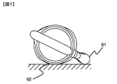
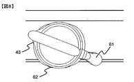
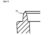
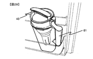
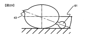
- FIG. 5 is a bottom view of FIG. 4. It is an enlarged view of the welding convexity 63 of FIG. It is a perspective view at the time of door pocket accommodation of the pot type water purifier concerning one embodiment of the present invention. It is a top view when the pot type water purifier which shows an example of the main body container shape concerning this invention is turned down sideways.
- FIG. 5 is a horizontal sectional view of the grip portion showing a positional relationship between the grip portion according to the present invention and a cartridge replacement time display member.
- FIG. 5 is a horizontal sectional view of the grip portion showing a positional relationship between the grip portion according to the present invention and a cartridge replacement time display member. It is a right view which shows the positional relationship of the holding part and cartridge replacement time display member which concern on this invention.
- FIG. 38 is a horizontal sectional view of the gripping part in FIG. 37.
- FIG. 5 is a horizontal sectional view of the grip portion showing a positional relationship between the grip portion according to the present invention and a cartridge replacement time display member.
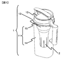
- FIG. 1 shows a schematic view of a pot type water purifier which is an embodiment of the present invention.
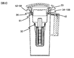
- FIG. 2 is a right side longitudinal sectional view of a pot type water purifier and a cartridge according to an embodiment of the present invention
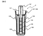
- FIG. 3 is a longitudinal sectional view of the cartridge.
- FIG. 24 is a front longitudinal sectional view of a pot-type water purifier and cartridge according to an embodiment of the present invention.
- FIG. 25 is an enlarged top view of the main body container sealing means in the pot-type water purifier according to one embodiment of the present invention in a loosened state.
- the pot type water purifier is composed of a main body 1 and a cartridge 2, and the main body 1 is composed of a main body container 11, an inner container 12, and a stopper 13.
- the cartridge 2 is used in a state in which it is inserted into the cartridge connecting portion 32 opened on the bottom surface of the inner container 12.
- the main body container 11 fixed the purified water storage part 14 below and the upper internal container receiving part 15 by ultrasonic welding.
- the purified water storage unit 14 and the inner container receiving unit 15 may be fixed with an adhesive, not limited to ultrasonic welding as long as there is no water leakage and a certain strength can be obtained.
- the inner container 12 has an outer peripheral screw 33 formed on the outer side, screwed into a screw 41 to form an inner side of the inner container receiving portion 15, and a main body container seal member attached to a packing large groove 106 provided below the outer peripheral screw 33.
- the main packing 11 and the inner container 12 are sealed by pressing the large packing 34 against the seal surface 42 provided on the inner lower side of the inner container receiving portion 15 and compressing it in the vertical direction.
- the main body container sealing means is not limited to this style.
- the main body container sealing means is mechanically sealed with a member having a claw used for a lunch box lid, or the elasticity of the inner container 12 is used. It may be a hermetically sealed structure.
- the stopper 13 is an internal container sealing member in which a male screw 51 formed on the outer side is screwed into an inner peripheral screw 35 formed on the inner side of the inner container 12 and attached to a packing small groove 58 provided above the male screw 51.
- the inner container 12 and the stopper 13 are sealed by pressing the small packing 52 against the seal surface 36 provided on the inner side of the inner container 12 and compressing it in the vertical direction.
- the inner container sealing means is not limited to this style.
- the inner container sealing means is mechanically sealed with a member having a claw used for a lunch box lid, or sealed by utilizing the elasticity of the material of the plug 13. The structure to do may be sufficient.
- the cartridge 2 includes a cap 121, a filtration filter 122, and an outer case 123.
- the filtration filter 122 is connected to the lower center position of the cap 121, and the outer case 123 is connected to the lower side of the cap 121 so as to cover the filtration filter 122.
- the filtration filter 122 includes a cylindrical outer mesh member 133 and an inner mesh member 134, and the inner space of the inner mesh member 134 serves as a raw water collecting part 135, and a filter medium is filled between the outer mesh member 133 and the inner mesh member 134.
- the filter medium filling unit 136 is filled with activated carbon, ion exchange resin, or the like.
- the raw water is put in the inner container 12, passes through the upper opening mesh member 138 from the upper opening 137 of the cap 121, and simultaneously passes through the inner mesh member 134, which is the raw water collecting part 135, the filter material filling part. 136. Thereafter, the cartridge is purified by the filter medium in the filter medium filling portion 136 and passes through the cartridge 2 through the outer mesh member 133 and six slits provided in the length direction extending to the lower end of the outer case 123.
- the stopper 13 is attached to the inner container 12, and only the inner container 12 and the stopper 13 are sealed as shown in FIG. 25, and the outer peripheral screw 33 of the inner container 12 and the female thread of the inner container receiving portion 15. If the pot-type water purifier is tilted while the space between 41 is loosened, it becomes possible to obtain purified water.
- the main body container 11 is composed of a purified water storage part 14 and an internal container receiving part 15, and the purified water storage part 14 is provided with a handle 61 composed of a gripping part 71, a connecting part 72, a cover 73 and a slider 74, and the purified water storage part 14 was provided with a spout 43.
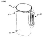
- FIG. 4 is a perspective view of the water purifier 14 according to an embodiment of the present invention
- FIG. 5 is a right side view of the pot-type water purifier according to the embodiment of the present invention with the cover 73 removed
- FIG. Fig. 7 is a vertical cross-sectional view of the handle 61 of the pot-type water purifier according to the embodiment
- Fig. 7 is a top view when the pot-type water purifier according to the embodiment of the present invention is turned sideways
- Fig. 8 is an embodiment of the present invention.
- FIG. 26 is a bottom view of FIG. 4
- FIG. 27 is an enlarged view of the welding protrusion 63 of FIG.
- FIG. 28 is a pot type according to an embodiment of the present invention.
- the perspective view at the time of storing the door pocket of the water purifier, FIG. 29 and FIG. 30 are respectively the top views when the pot type water purifier showing an example of the shape of the main body container according to the present invention is tilted sideways.
- the surface having the spout 43 is defined as the front surface
- the surface having the handle 61 is defined as the back surface
- the stopper 13 side is defined as the top surface.
- the water purifying water storage part 14 which comprises the lower part of the main body container 11 is a substantially rectangular parallelepiped liquid storage container having a bottom and a side, and has a handle 61 on the back surface.
- the pot type water purifier When the pot type water purifier is tilted sideways, the pot is grounded.
- a pedestal 62 for assisting the stable placement of the water purifier is provided on the upper right side.
- Plastic containers are weaker and easier to break than containers made of other materials such as iron or wood, and if there are corners, there is a risk of stress concentrating and breaking easily.
- the side surface is often formed with a curved surface. Therefore, the pot-type water purifier is also easy to roll when it is placed on its side, and it is easy to roll and unstable storage.
- the pot-type water purifier can be stably stored even when it is placed on its side.
- a plurality of pedestals 62 may be provided, but the pot-type water purifier can be placed stably if at least three locations of the water purifying water storage unit 14, the handle 61, and the pedestal 62 are grounded.
- the pedestal is preferably located at one upper position.
- the purified water reservoir 14 was made of polystyrene. At the upper end, as shown in FIG. 14, a welding projection 63 for ultrasonic welding with the inner container receiving portion 15 is provided over the entire circumference in the shape of FIG.
- the pot-type water purifier is conveniently a transparent container in which the filtration state and the amount of purified water can be easily confirmed.
- the purified water reservoir 14 is preferably made of highly transparent polystyrene or AS resin (acrylonitrile styrene resin).
- resin molded products such as polycarbonate, acrylic resin, polyethylene, ABS resin (acrylonitrile butadiene styrene resin), and polypropylene may be used.
- the center of gravity of the pot-type water purifier is located between the pedestal 62 and the purified water storage unit 14, and the pedestal 62 is the center of the right side surface of the purified water storage unit 14. However, it is more preferable to attach to the upper half.
- the handle 61 includes a gripping part 71 that is actually gripped by the user, a connecting part 72 that connects the purified water storage part 14 and the gripping part 71 up and down, a cover 73 that covers the gripping part 71 and the connecting part 72, and a cartridge use start time.
- a slider 74 carrier replacement time display member
- the connecting part 72 may be configured with only one gripping part 71, but the pot-type water purifier has a weight of about 4 [kg] when purified water or raw water enters. The load on the part 72 is large, and there is a risk that the connecting part 72 will break during repeated use.
- the connecting portion 72 is preferably two in the upper and lower directions.
- the handle 61 should just be connected with the purified water storage part 14, and a streamlined shape may be sufficient as it.
- the handle 61 is grounded together with the pedestal 62 and the purified water storage section 14 when the pot-type water purifier is tilted sideways as shown in FIG.
- the pot type water purifier can be supported at three points that surround the center of gravity of the pot type water purifier. Can be stored stably, tilted sideways.
- the spout 43 is arranged so that the center of gravity of the pot-type water purifier when the purified water is filled, the grip 71 of the handle 61 and the spout 43 are in a straight line.
- the center of gravity of the pot type water purifier, the gripping part 71 and the spout 43 being in a straight line means that the pot type water purifier is filled with purified water and has the gripping part 71 to inject purified water.
- the pouring spout 43 is directed downward, it indicates an arrangement in which the pouring spout 43 is positioned vertically below the gripping portion 71.
- the inner container receiving portion 15 has a shape with a horizontal section close to a circle
- the purified water storage portion 14 has a shape with a horizontal section close to a rectangle.
- the horizontal cross-sectional shape of 15 or the water purification water storage part 14 may be a shape such as an ellipse or a gourd as shown in FIGS.
- FIG. 6 is a longitudinal sectional view of a cover 73 according to an embodiment of the present invention
- FIG. 10 is a rear view of the cover 73 according to an embodiment of the present invention
- FIG. FIG. 12 is an enlarged view of the upper surface of the gripping portion 71 in FIG. 4
- FIG. 13 is a perspective view of a slider 74 according to an embodiment of the present invention
- FIG. 14 is according to an embodiment of the present invention.
- 15 is a longitudinal sectional view of the slider 74 as viewed from the left side
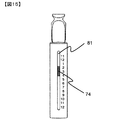
- FIG. 15 is a rear view of the handle 61 of the pot type water purifier according to the embodiment of the present invention.
- the cover 73 is a substantially semi-cylindrical hollow that forms the back side of the handle 61 and has a shape having an upper surface and a lower surface, and is formed of ABS resin.
- the upper surface overlaps with the upper connecting portion 72 and extends to the boundary between the purified water storage portion 14 and the inner container receiving portion 15, and further extends upward along the inner container receiving portion 15 to the upper end of the inner container receiving portion 15. Is formed in a bowl shape above the upper end of the inner container receiving portion 15.
- a vertical flat surface was provided in the center of the space of the bowl-shaped ridge portion to form an inner container fixing wall 82.
- the upper surface, the lower surface, and the substantially semi-cylindrical portion of the cavity are used to cover the grip portion 71.
- a vertically long elliptical window hole 81 having a major axis of about 10 [cm] and a minor axis of about 5 [mm] was opened in the vicinity of the center of the curved surface constituting the substantially semi-cylindrical portion.
- a cover fixing hole 83 having a diameter of about 1.5 [cm] was formed on the lower surface, and a cover fixing protrusion 84 having a diameter of about 1 [cm] and a height of about 3 [mm] was provided on the back side of the upper surface.
- a number is vertically applied to the right side of the window hole 81 by resin irregularities to form an effective period calendar 85 indicating the effective period of the cartridge.
- the window hole 81 of the cover 73 may have a shape other than an ellipse, and may not be in the center of the surface. The position and shape can be changed according to the design and the structure of the mold.
- the validity period calendar 85 may be provided on the left side or both sides of the window hole 81.
- the effective period calendar 85 does not need to be formed by resin irregularities, and may be any character, number, or symbol having a calendar function such as printing, sealing, or decorative insert molding. Since the cover has a substantially semi-cylindrical shape, printing, decorative insert molding, and sticking of a seal are difficult. However, if the cover is provided with resin irregularities, a product can be easily produced at a low cost, which is more preferable.
- the grip portion 71 has a finger hooking surface 97 that is a curved surface that forms the front side of the handle 61 and an upper surface and a lower surface that are extensions of the connecting portion 72.
- the outer shape of the handle 61 is formed by forming a single cylindrical shape by the substantially semi-cylindrical shape of the finger resting surface 97 and the cover 73.
- a surface orthogonal to the back surface of the finger hook surface 97 is provided on the back surface side of the finger hook surface 97, and used as a use start time display surface 91.
- a column 98 is provided on the rearmost part of the purified water reservoir 14 that is further outside the use start time display surface 91, and a window 92 having a shape that fits into the window hole 81 of the cover 73 is provided on the back side of the column 98. .
- the front side of the column 98 was a cylinder.
- a space for moving the slider 74 up and down is formed between the column 98 and the use start time display surface 91. The space was partially widened at the upper end, and a space for fitting the slider 74 was provided.
- a plurality of slider positioning recesses 95 are provided at equal intervals on the window 92 side on the right side surface of the use start time display surface 91.
- a cover fixing protrusion 93 for fixing the cover 73 having a diameter of about 1.5 [cm] and a height of about 2 [mm] is provided on the lower surface, and the height is reduced toward the back side.
- a cover fixing groove 94 for guiding the cover fixing protrusion 84 of the cover 73 to the cover fixing hole 99 is provided on the upper surface.
- the depth was about 1 [mm]
- the width was such that the cover fixing hole 99 side was narrow and the back side was wide.
- the cover fixing hole 99 has a diameter of about 1 [cm] and a depth of about 3 [mm] on the locking portion 72, and has a shape for fixing the cover fixing projection 84 of the cover 73.
- a method for attaching the cover 73 to the gripping portion 71 and the connecting portion 72 will be described.
- a cover fixing hole 83 on the lower surface of the cover 73 is hooked on the cover fixing protrusion 93 on the lower surface of the grip portion 71, and the cover fixing protrusion 84 on the back surface of the cover 73 is placed on the back side of the cover fixing groove 94 on the upper surface of the grip portion 71.
- the upper side of the cover 73 is pushed from the back side, and the cover fixing projection 84 is moved along the cover fixing groove 94 and fitted into the cover fixing hole 99 at the tip of the cover fixing groove 94.
- the cover fixing groove 84 Since the width of the cover fixing groove 94 on the upper surface of the grip portion 71 is increased toward the back side, the cover fixing groove 84 is inserted into the cover fixing groove 94 even though the cover fixing protrusion 84 is arranged on the back side of the upper surface of the cover 73. It is easy to do and the cover 73 can be installed smoothly.
- the slider 74 is used between the use start time display surface 91 of the gripping portion 71 and the column 98.
- the shape was close to that of H steel and was formed of ABS resin.
- the dent is directed to the front side and the back side, and is used at a position where the plane is the right side and the left side.
- the recess on the front side is recessed in a U-shape
- the recess on the back side is recessed in a semicircular shape
- the recess on the back side is fitted into the columnar shape of the column 98 of the grip portion 71.
- the slider 74 uses a partially expanded space provided at the upper end of the space provided in the gripping portion 71, applies a semicircular recess of the slider 74 to the semi-cylindrical portion of the column 98, and the right side surface of the slider 74 with the column 98 as a fulcrum. Rotate while pressing and insert.
- a positioning projection 101 that engages with the slider positioning recess 95 of the grip portion 71 and fixes the position of the slider 74 is provided below the right side surface inside the U-shaped portion.
- the positioning projection 101 may be on the left side inside the U-shaped part, or may be provided on both the left and right sides inside the U-shaped part.
- the slider 74 is fitted by sliding it down after being fitted into the upper end of the space.
- the positioning protrusion 101 may be at the center or upper side inside the U-shaped part, but if it is at the lower side, the moving distance until it fits into the nearest slider positioning recess 95 is small, and the inserted slider 74 can be fixed immediately. preferable.
- the positioning recess may be provided on the slider 74 and the slider positioning projection may be provided on the gripper 71.
- a use start arrow 102 is provided on the right side surface of the outer side of the U-shaped portion of the slider 74 by resin irregularities.
- the cover 73 is removed, the slider 74 is moved, and the use start arrow 102 is set to the corresponding number on the use start time calendar 96 on the grip 71.
- the slider 74 can be seen from the window hole 81 of the cover 73 through the window 92 of the grip portion 71 as shown in FIG.
- the replacement time calendar 85 arranged on the right side of the window hole 81, the upper end of the slider 74 represents the cartridge use start time, and the lower end represents the cartridge replacement time.
- the slider 74 cannot be touched unless the cover 73 is removed, it is possible to prevent the user from moving the slider 74 accidentally when the pot type water purifier is normally used.
- the range from the use start time of the cartridge to the replacement time is shown in the replacement time calendar 85, it is possible to inform the user how much the cartridge has been used for the life of the cartridge today. It is possible to give more information to the user than to display only the replacement time.
- the slider 74 is preferably a colored member that is easy to see through the window 92 in order to clearly communicate the effective period of the cartridge.
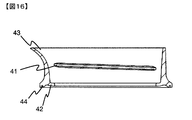
- FIG. 16 is a longitudinal sectional view as seen from the right side of the inner container.
- the inner container receiving portion 15 constituting the upper part of the main body container 11 is provided with a female screw 41 that can be fastened to the outer peripheral screw 33 of the inner container 12 on the inner wall and a large packing attached to the outer periphery of the inner container 12 below the female screw 41. It was made into the shape which has the sealing surface 42 which presses 34, and the spout 43 which pours purified water into the upper end, and formed with polystyrene. Moreover, the welding groove
- the portion 15 is preferably an opaque colored member.
- the colored raw material is melted by providing a welding convexity in the purified water reservoir 14 using the transparent raw material and a welding groove in the inner container receiving portion 15 using the colored raw material, and melting the transparent raw material during ultrasonic welding. Appearance defects due to erosion of the transparent member can be avoided.
- Water is poured from the gap between the seal surface 42 of the inner container receiving portion 15 and the packing size 34 of the inner container 12. It flows through the inner wall surface where the clean water female screw 41 is formed.
- the female screw 41 may be on the inner wall of the inner container receiving portion 15 more than once, but since the screw thread near the spout 43 is deleted, the purified water passes through this portion and the shape of the purified water flowing out is easy to pour. Further, since the screw thread near the handle 61 is also deleted, there is an effect that the core portion of the molding die can be made by a slide instead of a screw.
- the purified water storage part 14 and the inner container receiving part 15 may be resin molded products such as polypropylene, polycarbonate, acrylic resin, polyethylene, ABS resin (acrylonitrile butadiene styrene resin), and are connected and bonded by fitting with sealing performance. You may fix by the adhesion
- resin molded products such as polypropylene, polycarbonate, acrylic resin, polyethylene, ABS resin (acrylonitrile butadiene styrene resin), and are connected and bonded by fitting with sealing performance. You may fix by the adhesion
- Bonding by sonic welding is preferable because water leakage can be reliably prevented and elution by an adhesive can be reliably prevented.
- the inner container receiving part 15 is arranged on the purified water storage part 14.
- the purified water storage part 14 is easily stored in the door pocket of the refrigerator by being formed in a substantially rectangular parallelepiped shape that spreads upward from the bottom surface having a long side of about 11 [cm] and a short side of about 8 [cm] at a draft of 2 °. About 1.5 [cm] above, the opening was suddenly widened from a substantially rectangular parallelepiped, and the shape was a curved surface connected to the inner container receiving portion 15.
- the lower part of the substantially rectangular parallelepiped excluding the curved surface connected to the inner container receiving part 15 above the purified water storage part 14 is referred to as a substantially rectangular parallelepiped part.
- the inner container receiving portion 15 was formed in a substantially cylindrical shape having a maximum diameter of about 15 [cm] while the upper end of the substantially rectangular parallelepiped portion had a long side of about 12 [cm] and a short side of about 10 [cm].
- the inner container receiving portion 15 is formed larger than the outer shape of the substantially rectangular parallelepiped upper end without being limited by the dimension of the short side 10 [cm] at the upper end of the substantially rectangular parallelepiped portion of the purified water storage portion 14, so that the inner container mounted inside the inner container receiving portion 15.
- a maximum of about 10.5 [cm] was also secured for the inner diameter of 12. Since the maximum inner diameter is 10 [cm] or more, the user can easily put his hand inside the inner container 12 and can easily remove the cartridge 2.
- the pot-type water purifier when the pot-type water purifier is placed on its side, the outer periphery of the water-purifying water storage unit 14 and the inner container receiving unit 15 are grounded, so the pot-type water purifier is easy to roll and becomes unstable storage. Since the handle 61 is grounded, there is an advantage that the pot-type water purifier can be prevented from rolling, and can be stably tilted and stored.
- FIGS. 17 is a cross-sectional view of the inner container according to one embodiment of the present invention as viewed from the right side
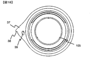
- FIG. 18 is a top view of the inner container according to one embodiment of the present invention
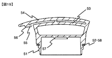
- FIG. 19 is according to one embodiment of the present invention. Sectional drawing seen from the right side of the stopper is shown, respectively.
- the inner container 12 was formed in a high-impact polystyrene having a bowl-like shape having an opening of the cartridge connection portion 32 on the bottom surface and a water supply port 31 for feeding raw water upward.
- Three cartridge fixing protrusions 105 are arranged at equal intervals on the inner wall of the cartridge connection portion 32. When repeatedly performing the operation of placing the pot type water purifier upright or tilting it sideways, the force of the moment is applied to the cartridge connection part 32 due to the weight of the cartridge 2 and the cartridge connection part 32 may come loose. is there.
- Three cartridge fixing protrusions 105 having a thickness of 0.9 [mm] are provided on the inner wall of the cartridge connecting portion 32 with respect to a gap of 0.6 [mm] with the cartridge 2.
- an outer peripheral screw 33 is provided above, and a large packing groove 106 is provided below the outer peripheral screw 33, and a large packing 34 is attached.
- an inner peripheral screw 35 is provided above, and a seal surface 36 is provided on the inner peripheral screw 35.
- a part of the upper end is formed as a surface 37 that covers the spout.
- the surface 37 covering the spout is provided with a notch 38 at a position near the tip of the spout 43, and a locking projection 39 having a height of about 3 [mm] is provided at substantially the center of the surface 37 covering the spout. It was.
- the outer peripheral screw 33 was formed with a double thread and was fastened with a female screw of the inner container receiving portion 15.
- the clean water is poured by loosening the space between the outer peripheral screw 33 of the inner container 12 and the female screw 41 of the inner container receiving portion 15. Because of the double thread, the inner container 12 can be moved upward with less rotation than the single thread, and a flow path for pouring purified water can be secured, making it easy to pour.
- the outer peripheral screw 33 is screwed in, and the large packing 34 is pressed against the sealing surface 42 of the inner wall of the inner container receiving portion 15 to compress it, thereby sealing the purified water accumulated in the purified water storage portion 14 from leaking out.
- the stopper 13 has a shape composed of a side surface having a thread on the outer periphery and a top surface, and is used by being screwed into an inner peripheral screw 35 of the inner container 12.
- a male thread 51 is provided with a single thread on the outer periphery of the side surface, and a small packing 52 is mounted in a small packing groove 58 on the male thread 51 for use.
- the male screw 51 is screwed into the inner peripheral screw 35 of the inner container 12, and the small packing 52 is pressed against the sealing surface 36 of the inner container 12 and compressed to seal the raw water remaining in the inner container 12 from leaking out.
- a circumferential rib 57 having a height of about 2 [mm] was provided on the back side of the top surface of the stopper 13.
- the side surface of the other cartridge 200 does not contact the cartridge fixing protrusion 105 provided on the inner wall of the cartridge connecting portion 32 of the inner container 12, and the cartridge fixing protrusion 105 is effective. Absent.
- the top surface is provided with a handle 53 having the same length as the outer diameter of the top surface. Since the stopper 13 can be turned by grasping the handle 53, the male screw 51 can be easily screwed.
- the handle 53 is on the front and the water purifier 14 is stored on the shelf, the pot-type water purifier can be easily removed using the handle 53 on the front. be able to. Furthermore, even when a pot-type water purifier is stood and stored in a drawer at a low position in a refrigerator such as a vegetable room, it can be easily taken out by holding the handle 53 and pulling up the pot-type water purifier. .
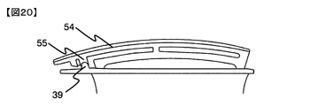
- FIGS. 20 is a right side view of an assembled state of an inner container and a stopper according to an embodiment of the present invention
- FIG. 21 is a front view of the state of FIG. 20
- FIG. 22 is an assembled product according to an embodiment of the present invention
- FIG. 23 is a top view showing the positions of the inner container and the cover when the stopper is rotated 180 degrees according to an embodiment of the present invention.
- the main body container 11 and the inner container 12, and the inner container 12 and the stopper 13 are respectively sealed by screwing to prevent water leakage of purified water and raw water.
- the screw between the main body container 11 and the inner container 12 is loosened, the purified water stored in the purified water storage part 14 can be poured, and the screw between the inner container 12 and the stopper 13 does not need to be loosened.
- the inner container 12 does not have a grip portion, and the operation of rotating the inner container 12 while holding the side surface of the inner container 12 is very inconvenient.
- the handle cannot be attached to the stopper 13, and the handle of the stopper 13 and the portion that the inner container 12 can be gripped interfere with each other.
- the handle cannot be attached to the stopper 13, and the handle of the stopper 13 and the portion that the inner container 12 can be gripped interfere with each other.
- the plug 13 is removed from the inner container 12 but also the screw between the main body container 11 and the inner container 12 is loosened to loosen the inside of the main body container. Without securing the air outlet, the air in the main body container cannot be discharged without tightening the screw, so that the raw water cannot flow into the cartridge 2. Every time raw water is supplied and filtered, the two screws must be opened, which is also not easy to use.
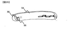
- a lever 54 is attached to the handle 53 of the stopper 13, and the hook protrusion 55 and the hook protrusion 55 are provided on the back side of the lever 54. Further, two protrusions, a semicircular climbing protrusion 56 having a thickness of about 2 [mm] and a height of about 3 [mm], which are located further outside are provided.
- the stopper 13 First, open the stopper 13 by turning about 5 °.
- the hooking protrusion 55 comes into contact with the locking protrusion 39 provided on the surface 37 that covers the spout of the inner container 12.
- the stopper 13 is rotated and opened while the hooking protrusion 55 is hooked on the stopper protrusion 39, so that the inner container 12 is interlocked with the stopper 13 and starts rotating together.
- the hooking protrusion 55 and the locking protrusion 39 correspond to the locking means. In the range in which the stopper 13 is turned by 10 to 180 °, the sealing of the large packing 34 of the inner container 12 and the sealing surface 42 of the inner container receiving portion 15 is released, and purified water can be poured.
- the stopper 13 When the stopper 13 is rotated by about 180 °, the overhanging protrusion 56 comes into contact with the upper end of the cover 73 of the handle 61. If the stopper 13 is further rotated and opened as it is, the climbing projection 56 rides over the upper end of the cover 73, so that the lever 54 is elastically deformed upward by about 3 [mm]. At this time, the notch 38 of the inner container 12 hits the inner container fixing wall 82 of the cover 73, and the inner container 12 stops at a position rotated by 180 °. In the present embodiment, the inner container fixing wall 82 corresponds to the stopping means.
- the climbing projection 56 climbs over the upper end of the cover 73 while the inner container 12 is stopped, and the latching state of the latching projection 39 and the hooking projection 55 is released as shown in FIG.
- the cover 73 corresponds to the release means. If the stopper 13 is further rotated and opened in this state, the stopper 13 can be removed. When the stopper 13 is removed, the sealing of the packing size 34 of the inner container 12 and the sealing surface 42 of the inner container receiving part 15 is released, and when the raw water is put into the water supply port 31 above the inner container 12, the raw water is not dead. It passes through the cartridge 2 and is filtered.
- the hooking protrusion 55 hits the engaging protrusion 39, the stopper 13 and the inner container 12 start rotating together, and when further turned, the inner container 12 and the inner container receiving part 15
- the screw between the stopper 13 and the inner container 12 begins to fasten.
- the screw is fastened, first, the large packing 34 of the inner container 12 and the sealing surface 42 of the inner container receiving portion 15 are in a sealed state, then the hooking protrusion 55 gets over the locking protrusion 39, and finally, the plug 13
- the space between the small packing 52 and the sealing surface 36 of the inner container 12 is sealed. Since the left side of the locking projection 39 is inclined, the hooking projection 55 can easily get over the locking projection 39 after the screw is fastened.
- the internal container 12 is hermetically sealed by screwing the male screw 51 of the stopper 13 into the inner peripheral screw 35 of the internal container 12 and compressing the small packing 52 on the sealing surface 36 of the internal container 12 in the vertical direction.
- the main body container 11 is hermetically sealed by screwing the sealing means and the outer peripheral screw 33 of the inner container 12 into the female thread 41 of the inner container receiving part 15 and compressing the large packing 34 onto the sealing surface 42 of the inner container receiving part 15 in the vertical direction.
- the main body container sealing means is composed of different sealing means. Therefore, even if the pot-type water purifier is placed sideways with the purified water or raw water before filtration, the purified water and raw water will not leak out, and the purified water and raw water will not be mixed. Since the pot-type water purifier can be stored in a horizontal position, the storage location and orientation can be freely selected, such as laying it on a shelf in the refrigerator when it does not fit in the refrigerator door pocket.
- the plug 13 is rotated and opened while the hooking protrusion 55 of the stopper 13 is hooked on the locking protrusion 39 of the inner container 12, and the inner container 12 rotates together with the stopper 13. Therefore, by turning the stopper 13 by 10 to 180 °, only the screw between the main body container 11 and the inner container 12 can be loosened and the purified water can be poured.
- the overpass projection 56 of the stopper comes into contact with the upper end of the cover 73 of the handle 61, the overturning protrusion 56 gets over the upper end of the cover 73, and the locking protrusion 39 and the hooking protrusion 55 are locked. Therefore, it is possible to supply the raw water by loosening the screw between the inner container 12 and the stopper 13 only by rotating the stopper 13 by 180 ° or more.
- the notch 38 of the inner container 12 hits the inner container fixing wall 82 of the cover 73, and the inner container 12 stops at a position rotated 180 °. Since the stop means is provided, the locked state can be reliably released.
- the main body container sealing means is formed with a double thread screw and the inner container sealing means is formed with a single thread screw, when the two screws are tightened with the stopper 13, the single container screw inner container sealing means is easier to tighten. Therefore, there is an effect that the main body container sealing means can be easily opened first when opening with the stopper 13. Further, since the double screw can move the inner container 12 upward with less rotation than the single screw, there is an effect that it is easy to ensure a flow path for pouring clean water and to pour easily.
- Patent No. 3954971 adopts a shape with a semi-circular horizontal cross section so that the front side of the spout is easy to pour, and the horizontal cross section maintains a square shape so that the upper side of the back side can be placed stably.
- a hermetic chilled water bottle having a horizontal section with a concave center and a handle within the recessed area.
- the center of the horizontal cross section is recessed, there is a space that is thin on both sides of the recess and cannot be washed, which is unfavorable for hygiene.
- there is a conventional cold water tube shape that can be stored by tilting sideways by eliminating a handle and configuring a part of the side surface as a flat surface.
- the purified water storage portion 14 The shape of the pot-type water purifier that touches down at the same time as the bottom. It has the effect of preventing rolling when placed sideways and allowing stable storage.
- the pouring spout 43 is always positioned vertically below the grip 71 when pouring clean water. There is an effect that the spout 43 is positioned at a position where the user can easily pour it without adjustment.
- the pot can be easily stored in the door pocket of the refrigerator and can obtain a large amount of purified water at once. Realized the special advantages of the water purifier. Even when the shape is such that it is easy to roll when placed sideways, it can be stably stored because the lower portion of the clean water storage section 14 and the gripping section 71 are in contact with each other at the same time.
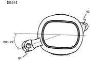
- the shape of the pot-type water purifier that can be easily stored in the door pocket of the refrigerator and can obtain a large amount of purified water at one time is such that the handle 61 has a short side or a long side of the substantially rectangular parallelepiped part of the purified water storage part 14 as shown in FIG. By inclining by 20 to 25 ° with respect to the side, it is possible to form a shape that allows the pouring spout 43 to be easily poured and positioned vertically below the gripping portion 71.
- water purification has a function that allows the user to replace the cartridge without fail by displaying the cartridge filtration capacity decline time in advance on the water purifier.
- the cartridge replacement time display member indicating the replacement date is attached to the back of the lid, when the lid is removed to put tap water, the replacement display member may be turned accidentally and the replacement date may not be known. there were.
- the cartridge replacement time display member becomes large, and a wide space for mounting the cartridge replacement time display member is required. In some cases, the pot type water purifier itself becomes large, or the capacity to which the cartridge replacement time display member is attached is bulky, so that the capacity is reduced.
- the present embodiment is provided with a cartridge replacement time display means in the handle 61 that has conventionally been a dead space that is only gripped by the user. Since it is not necessary to prepare a space for cartridge replacement timing means, the pot type water purifier itself can be made compact.
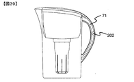
- a slider 74 is movably mounted as a cartridge replacement time display member 202 that indicates the effective period of the cartridge so that the gripping portion 71 is sandwiched, so that the slider 74 can be moved relative to the effective period calendar 85 to change the time of the year. Even when the use of the cartridge is started, the replacement time of the cartridge can be expressed.
- the gripper 71 is provided with a slider positioning recess 95 as a positioning recess and the positioning convex portion 101 is provided inside the slider 74, the slider 74 can be fixed at a fixed position during the use period of the cartridge.
- the effective period of the cartridge is prevented from easily changing.
- the space of the handle 61 can be used most effectively. Since the moving range of the slider 74 can be made large, the range in which the characters of the effective time calendar 85 can be displayed can be made large, and an easy-to-see display in which each character is large can be performed.
- the cover 73 is attached to the grip portion 71 to which the slider 74 is attached, and the slider 74 cannot be touched unless the cover 73 is removed.
- the effect which prevents that a user moves the slider 74 accidentally while using a pot type water purifier can be heightened further. Since the window 73 is provided in the cover 73 and the slider 74 is structured so as to be visible from the outside of the cover 73, the valid period of the cartridge can be confirmed with the cover 73 attached. Since it is not necessary to remove the cover 73 during use, the frequency with which the slider 74 is touched and moved by mistake can be reduced.
- the use start time calendar 96 is arranged on the grip 71.
- the use start arrow 102 of the slider 74 is aligned with the number corresponding to the cartridge use start time, and the cover 73 is placed over the cover 73 so that the slider 74 indicates the effective period of the cartridge.
- Calendar 85 letters were arranged. The effective period of the cartridge can be displayed without considering the user.
- the present embodiment has cartridge replacement time display means that can prompt the preparation of a replacement cartridge, and there is no need to prepare a space for attaching the cartridge replacement time display means. Furthermore, the problem of providing a water purifier that can obtain safe and delicious water is solved by adopting an attachment method that does not cause the user to move accidentally.
- the cantilever lever 54 may be a single support at the end of the lever 54, but a lever support 200 may be added near the center of the lever 54 as shown in FIG. Preventing the lever 54 from being easily lifted and damaged by the small force that a hand catches or a child plays by shortening the distance between the climbing projection 56, which is an action point, and the support, which is a fulcrum, by increasing the support. it can.
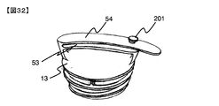
- a technique for preventing the above-mentioned breakage by attaching a stopper 201 to the lever 54 so that the lever can be lifted only to a certain height.
- the stopper there are a shape in which the lever 54 and the handle 53 are sandwiched in the width direction as shown in FIG. 31, and a shape in which a pin is formed so as to penetrate the lever 54 and the handle 53 so as not to come off.
- the lever 54 may be constituted by another member that is detachably attached to the handle 53.
- the lever 54 is attached using a hinge structure so that the lever 54 is moved up and down as shown in FIG. 33, the lever 54 comes off when the lever 54 is lifted more than necessary, so that the damage is not generated.
- the lever 54 and the handle 53 are respectively fitted with a convex or concave shape separately from the shaft and the bearing as shown in FIG. It is preferable because the lever 54 can be prevented from easily coming off by the reaction force of the tangential force generated at 39.
- the locking means is not limited to the mechanism in which the locking projection 39 and the hooking projection 55 are in contact with each other on the side surface and hooks in the rotation direction of the stopper 13, but is locked on the surface 37 that covers the spout of the inner container 12.
- a mechanism may be provided in which a recess is provided, and the hooking protrusion 55 on the back side of the lever 54 of the stopper 13 is fitted in the locking recess to interlock the inner container 12 and the stopper 13 by fitting in the vertical direction.
- the hooking protrusion may be on the inner container 12 and the locking recess may be on the lever 54.
- the lever 54 and the handle 53 may have a shape as shown in FIG. 35, in which a claw is provided on the back of the lever 54 and the upper surface of the handle 53, and the lever 54 is pushed from above the handle 53 and is engaged with each other. it can. In this case, the lever can be moved up and down using the space provided for fitting the claws. If this vertical movement is utilized, it is not necessary for the lever 54 to be elastically deformed in the release means in which the climbing projection 56 provided on the back side of the lever 54 climbs over the upper end of the cover 73. The possibility that the lever 54 may be damaged due to repeated elastic deformation can be eliminated. In addition, by adjusting the amount of catches, it is possible to realize a shape in which the lever 54 is detached from the handle 53 when the lever 54 is lifted more than necessary, and the lever 54 can be prevented from being damaged due to misuse. .
- the handle 53 may be provided with an extendable bar 106 that can be expanded and contracted in the radial direction of the stopper 13.
- the telescopic bar 106 has an elastic member such as a spring, and has a rounded end.
- a hooking projection 55 is provided on the back side of the telescopic bar 106, and normally the stretched state is maintained.
- the inner container 12 and the stopper 13 are both rotated by the locking means by the locking protrusion 39 and the hooking protrusion 53.
- the handle 53 is turned about 180 °, the rounded tip of the telescopic bar 106 contacts the side surface of the cover 73 of the handle 61.
- the telescopic bar 106 is pushed by contact with the cover 73 and contracts in the radial direction of the plug 13 on the handle 53. It is possible to make a configuration in which the engagement state of the engagement protrusion 39 and the hook protrusion 55 is released by the release means that the cover 73 pushes the expansion / contraction bar 106 contracts.
- the main body container sealing means is formed by a double thread and the inner container sealing means is formed by a single thread.
- the same number of threads and the same pitch are adopted for the main body container sealing means and the inner container sealing means. May be.
- screws with different numbers of threads may be used, or screws with the same number of threads and different pitches may be used.
- either the main body container sealing means or the inner container sealing means is in a tight and easy-to-tight state.
- the inner container 12 can be interlocked with the stopper 13 even if the shape does not have the locking means.
- seal members that generate different frictional forces on the seal members of the main body container sealing means and the inner container sealing means may be selected.
- the effect can also be achieved by selecting flat packing with different hardness.
- a structure such as a turnbuckle that loosens both sides of the sandwiched member at the same time and rotates them simultaneously by rotating the member sandwiched between the right and left screws may be used.
- the stopper 13 and the main body container 11 are connected, the right and left screws are cut off on both sides of the inner container 12, and the stopper 13 and the main body container 11 are respectively attached, the inner container 12 is rotated, thereby sealing the inner container.
- An interlocking structure in which the means and the main body container sealing means can be simultaneously tightened or loosened can be realized.
- the main body container sealing means When a double thread screw is used for the main body container sealing means, there are two positional relationships when the main body container 11 and the inner container 12 are fastened.
- the inner container 12 may be fastened to any position, the inner container 12 is designed to be 180 °, thereby giving an easy-to-use impression.
- the inner container 12 may be interlocked with the stopper 13 using a magnet.
- an electromagnet may be used so that the inner container 12 is interlocked with the stopper 13.
- the electromagnet can be switched on and off by bringing the handle 53 and the lever 54 into contact with each other or separating them. Good, easy to use and preferred.
- the main body container sealing means and the inner container sealing means need only exhibit a sealing effect that prevents raw water and purified water from leaking when the pot-type water purifier is placed sideways, and the sealing member is a flat packing, O-ring Further, an elastic body such as a silicon member that is specially molded so as to be fitted to the member may be used.
- the main body container sealing means and the inner container sealing means are not limited to the combination of the sealing member and the screw described above, but are fixed in a shape having a bayonet mechanism or a tab in addition to the screw, for example, a tab used for a lunch box lid. It may be a combination of a sealing member and a mechanism that mechanically seals with a member having the same.
- a mechanism for sealing with a combination of a patchon tablet and a seal member may be used, and further, a method for sealing using the elasticity of the raw material of the lid itself may be used.
- the groove for fitting the lower O-ring has a smaller diameter than the groove for fitting the upper O-ring.
- a taper in which the inner diameter below the upper part is reduced is provided on the inner wall of the inner container 12.
- the sealing effect of the O-ring occurs, and the inner container 12 can be sealed by the O-ring simply by pushing the stopper 13 into the inner container 12.
- the stopper 13 When the stopper 13 is removed, the O-ring rolls due to friction with the inner wall of the inner container 12 and moves from the upper groove of the stopper 13 to the lower groove. Since the diameter of the lower groove is smaller, the O-ring is separated from the inner wall of the inner container 12, and the sealed state can be released.
- This mechanism can also be used as a main body container sealing means.
- the seal member may be attached to any member among a plurality of members that make a seal.
- the large packing 34 which is a sealing member of the main body container sealing means is attached to the inner container 12, but the large packing 34 may be attached to the main body container 11.
- a sealing member for inner container sealing means may be attached to the inner container 12.
- the stopper 13 fitted with the seal member may have a structure connected to the main body container 11 or the inner container 12 by a hinge mechanism.
- the stopper 13 is provided with a claw, the opening button and the claw are connected using a spring, and the inner container 12 is provided with a claw hooking recess in which the claw of the stopper 13 is caught.
- the stopper 13 is fixed to the inner container 12 by an inner container sealing means in which the tab of the stopper 13 is caught in the recess of the inner container 12.
- the opening button is pressed, the claw is released from the nail latch by the force of the spring connected to the opening button.
- the spring may be attached to the claw recess.
- the claw, the spring, the opening button, and the claw engaging recess may be provided in any of the plug 13 and the inner container 12 or the plug 13 and the main body container 11, respectively.
- the stopper 13 is not limited to being connected to the inner container 12 but may be connected to the main body container 11.
- a structure in which the main body container sealing means is formed by closely attaching the inner container 12 and the main body container 11 by sandwiching the outer periphery of the inner container 12 and the main body container 11 fitted with the seal member at the same time.
- the shape sandwiching the outer periphery may be provided in the inner container 12 or the main body container 11 or may be formed by another member. By loosening the pinching of the outer periphery, the main body container can be loosened and purified water can be poured. It is preferable that the sealing and the release of the sealing can be performed with one touch, and it is preferable to provide a plurality of shapes sandwiching the outer periphery so that the sealing effect is enhanced.
- the main body container 11, the inner container 12, and the stopper 13 need to prevent the raw water and the purified water from leaking out when the pot-type water purifier is placed sideways.
- the present embodiment in which sealing means is provided in each of the main body container 11 and the inner container 12 and the inner container 12 and the stopper 13 is the most effective sealing method for the above purpose.
- the container 12 is not hermetically sealed, by fastening the stopper 13, the main body container 11 and the stopper 13, the inner container 12 and the stopper 13 can be sealed, and a structure in which each of the raw water and purified water does not leak can be realized. Is possible.
- the main body container sealing means refers to means constituted by the main body container 11 and the stopper 13 and a seal member attached to either the main body container 11 or the stopper 13, and the inner container sealing means includes the inner container 12 and the stopper 13.
- the female screw 41 and the inner peripheral screw 35 may be provided on the entire inner wall of the inner container receiving portion 15 and the inner container 12 or may have a partially deleted shape.
- the horizontal cross-sectional shape of the purified water storage section 14 is not limited to a substantially rectangular shape, but may be a polygon such as a rhombus. Further, the horizontal cross-sectional shape of the inner container receiving portion 15 is not limited to a substantially circular shape, but may be a shape having a curve such as an ellipse or a gourd shape, and a polygon may be adopted in accordance with the sealing mechanism.
- the handle 61 has the effect that it can be stably stored if it is grounded when the pot-type water purifier is tilted sideways and stored.
- the spout 43 is not limited to the shape provided in a straight line with the center of gravity of the pot-type water purifier filled with the gripping portion 71 and the water purifier, and is directed horizontally when the pot-type water purifier is stored sideways. May be.
- the pot-type water purifier when stored in the door pocket of the refrigerator with the right side facing forward, it has a shape that extends to the right front, but even if it has a shape that extends to the left front good. There is an effect that a left-handed user can easily take out. Further, there are conveniences such as easy removal when stored in the door pocket of the door that opens with the left side of the refrigerator as the axis, and removal with the left hand that is free when the door that opens with the right side as the axis is opened with the right hand.
- the handle 61 is preferably movable.
- the handle 61 and the spout 43 may be provided close to each other.
- the pot type water purifier is poured down to pour water, but when the handle 61 is on the front side and the spout 43 is on the left side, Since the water purifier can be tilted to the left side to pour water, it is easier to move the wrist than the aforementioned shape.
- two spouts 43 may be provided in the vicinity of ⁇ 90 ° around the handle 61.
- the cartridge replacement time display member 202 may be slid as in the present embodiment, but is fixed only by friction between the cartridge replacement time display member 202 and the handle 71 or the gripper 61 by being fitted. Also good.
- the handle 61 into which the cartridge replacement time display member 202 is fitted may be formed in a curve, and the gripping portion 71 and the connecting portion 72 may be smoothly connected in a series of curves.
- the cartridge replacement time display member 202 when the cartridge replacement time display member 202 is housed in the recess of the handle 61 or the grip portion 71, the cartridge replacement time display is displayed when the pot type water purifier is used without the cover 73 being attached. The frequency with which the member 202 is moved by mistake can be reduced.
- the cartridge replacement time display member 202 does not move carelessly. It is preferable to provide a convex portion on the cartridge replacement time display member 202 because the cartridge replacement time display member 202 can be easily moved by having the convex portion only when changing the cartridge replacement time. Even if the convex portion is formed in a concave shape, the same effect can be obtained.
- the cartridge replacement time display member 202 has a function of indicating the effective period of the cartridge, if several types of cartridge replacement time display members 202 having different sizes are prepared, the corresponding cartridge is adapted to the life of the cartridge to be used.
- the replacement time display member 202 can be selected and used.
- cartridge replacement time display member 202 not only the cartridge replacement time display member 202 but also a cartridge replacement time display means may be provided by arranging an LED light so as to be parallel to the effective period calendar 85 and lighting only the portion corresponding to the effective period of the cartridge. good.
- the cartridge replacement time display means is not limited to a movable cartridge replacement time display member such as a slider, but may be a display using a dial or a digital display.
- Rotating the dial may display a character indicating the cartridge replacement time from the window 92 provided in the cover 73.
- the user may indicate the replacement time of the cartridge on paper, film, seal, etc., and the cover 73 may be attached after being sandwiched or stuck on the gripping portion 71, and the replacement time of the cartridge may be confirmed through the cover 73.
- the cartridge replacement time display means is not limited to the form using the validity period calendar 85, but a multi-color LED light is arranged. For example, blue light is lit when the cartridge is first used, and yellow light is turned on when the replacement time is approaching. A method of prompting the replacement time by the color of the light may be used, such as red light is turned on at the time.
- cartridge replacement time display means may be provided on the handle 53 of the stopper 13.
- a cartridge replacement time display means is provided in the dead space of an existing member, so that it is possible to finish the compact size without reducing the capacity.
- the cartridge replacement time display means provided on the handle 53 can employ the same mechanism as the cartridge replacement time display means provided as described above.
- the handle 61 may be provided on the inner container 12 or the stopper 13.
- the handle 61 is preferably provided in the main body container 11.
- the present invention can be applied not only to pot-type water purifiers but also to liquid containers for storing tea leaves or coffee powder and storing tea or coffee inside, but the application range is limited to these. It is not a thing.
- Main body part 2 Cartridge 11: Main body container 12: Internal container 13: Stopper 14: Water storage part 15: Internal container receiving part 31: Water supply port 41: Female screw 43: Spout 71: Grasping part 72: Connection part
Landscapes
- Life Sciences & Earth Sciences (AREA)
- Hydrology & Water Resources (AREA)
- Engineering & Computer Science (AREA)
- Environmental & Geological Engineering (AREA)
- Water Supply & Treatment (AREA)
- Chemical & Material Sciences (AREA)
- Organic Chemistry (AREA)
- Water Treatment By Sorption (AREA)
- Treatment Of Water By Ion Exchange (AREA)
Abstract
本発明は、主に家庭で使用し、水道水をろ過する家庭用浄水器に関するものであり、横向きに倒して保管した場合も水道水や浄水が漏れ出ることがなく、向きや場所を選ばず保管できる浄水器を提供する。より具体的には、原水の給水口を有する内部容器と、内部容器の底部に装着し原水を浄化するカートリッジと、内部容器を固定しカートリッジで浄化された浄水を入れる本体容器と、内部容器の給水口に装着する栓とを有する浄水器であって、栓で内部容器を密閉するための内部容器密閉手段と、内部容器で本体容器を密閉するための本体容器密閉手段とを有する浄水器を提供する。
Description
本発明は、主に家庭で使用し、水道水をろ過する家庭用浄水器に関する。
ポット型浄水器は、注ぎ口付きフタと内部容器と本体容器で構成され、内部容器にカートリッジを装着して使用する。各部材は嵌合で固定され、内部容器に入れた水道水は自重でカートリッジ内を通過して浄水となる構成である。保管している間に自重ろ過が完了するよう、従来、ポット型浄水器は立てて保管する形状が一般的であり、また、ポット型浄水器は飲料用途として使用されることが多く、冷蔵庫で保管する使用者が多かった。
しかし、冷蔵庫にはポット型浄水器を立てて保管できる場所が限られており、保管場所に困っている使用者が多い現状がある。冷蔵庫内大半のスペースを占める棚に、ポット型浄水器を横向きに倒して保管することを試みるが、従来の形状は各部材を嵌合で固定しているため、横向きに倒して保管すると、水道水や浄水が漏れ出る場合があった(特許文献1)。
本発明は、上述のような問題点を鑑み、横向きに倒して保管した場合も水道水や浄水が漏れ出ることがなく、向きや場所を選ばず保管できる浄水器を提供することにある。
前記課題を解決するため、本発明の浄水器は下記の構成から成る。すなわち、
本発明によれば、原水の給水口を有する内部容器と、前記内部容器の底部に装着し原水を浄化するカートリッジと、前記内部容器を固定し前記カートリッジで浄化された浄水を入れる本体容器と、前記内部容器の給水口に装着する栓とを有する浄水器であって、前記栓で前記内部容器を密閉するための内部容器密閉手段と、前記内部容器で前記本体容器を密閉するための本体容器密閉手段とを有することを特徴とする浄水器が提供される。
本発明によれば、原水の給水口を有する内部容器と、前記内部容器の底部に装着し原水を浄化するカートリッジと、前記内部容器を固定し前記カートリッジで浄化された浄水を入れる本体容器と、前記内部容器の給水口に装着する栓とを有する浄水器であって、前記栓で前記内部容器を密閉するための内部容器密閉手段と、前記内部容器で前記本体容器を密閉するための本体容器密閉手段とを有することを特徴とする浄水器が提供される。
また、本発明の好ましい形態によれば、前記本体容器密閉手段は、前記本体容器または前記内部容器のいずれか一方に形成されためねじと、他方に形成されたおねじと、本体容器シール部材とである浄水器が提供される。
また、本発明の好ましい形態によれば、前記内部容器密閉手段は、前記内部容器または前記栓のいずれか一方に形成されためねじと、他方に形成されたおねじと、内部容器シール部材とである浄水器が提供される。
また、本発明の好ましい形態によれば、前記栓を開くと、前記内部容器が連動する浄水器が提供される。
また、本発明の好ましい形態によれば、前記栓と前記内部容器が回動し、前記内部容器と前記栓とに、前記栓の回転力を前記内部容器に伝達する係止手段が設けられている浄水器が提供される。
また、本発明の好ましい形態によれば、前記本体容器に、前記係止手段による係止を解除する解除手段を有する浄水器が提供される。
また、本発明の好ましい形態によれば、前記本体容器は取っ手を有し、前記解除手段が前記取っ手に備わっている浄水器が提供される。
また、本発明の好ましい形態によれば、前記本体容器に、前記栓の開栓動作に伴う前記内部容器の連動を停める停止手段を有する浄水器が提供される。
また、本発明の好ましい形態によれば、前記本体容器は取っ手を有し、前記停止手段が前記取っ手に備わっている浄水器が提供される。
また、本発明の好ましい形態によれば、本体容器密閉手段は、おねじとめねじの回転動作により内部容器を本体容器に対し上下方向に移動させ、本体容器シール部材を上下方向に圧縮することで密閉する浄水器が提供される。
また、本発明の好ましい形態によれば、内部容器密閉手段は、おねじとめねじの回転動作により栓を内部容器に対し上下方向に移動させ、内部容器シール部材を上下方向に圧縮することで密閉する浄水器が提供される。
また、本発明の好ましい形態によれば、前記本体容器密閉手段と前記内部容器密閉手段のいずれか一方が二条ねじで、他方が一条ねじで形成される浄水器が提供される。
また、本発明の好ましい形態によれば、前記本体容器密閉手段が二条ねじで形成され、前記内部容器密閉手段が一条ねじで形成される浄水器が提供される。
本発明は、上記の構成により以下の優れた効果を奏することができる。すなわち、
本発明によれば、原水の給水口を有する内部容器と、前記内部容器の底部に装着し原水を浄化するカートリッジと、前記内部容器を固定し前記カートリッジで浄化された浄水を入れる本体容器と、前記内部容器の給水口に装着する栓とを有する浄水器であって、前記栓で前記内部容器を密閉するための内部容器密閉手段と、前記内部容器で前記本体容器を密閉するための本体容器密閉手段とを有することにより、浄水や原水が入った状態でポット型浄水器を横向きに倒して置いても、浄水および原水が漏れ出ることがなく、また、浄水と原水が混じることもないポット型浄水器を実現することができる。
本発明によれば、原水の給水口を有する内部容器と、前記内部容器の底部に装着し原水を浄化するカートリッジと、前記内部容器を固定し前記カートリッジで浄化された浄水を入れる本体容器と、前記内部容器の給水口に装着する栓とを有する浄水器であって、前記栓で前記内部容器を密閉するための内部容器密閉手段と、前記内部容器で前記本体容器を密閉するための本体容器密閉手段とを有することにより、浄水や原水が入った状態でポット型浄水器を横向きに倒して置いても、浄水および原水が漏れ出ることがなく、また、浄水と原水が混じることもないポット型浄水器を実現することができる。
また、本発明の好ましい形態によれば、前記本体容器密閉手段は、前記本体容器または前記内部容器のいずれか一方に形成されためねじと、他方に形成されたおねじと、本体容器シール部材とであることにより、ポット型浄水器の内部容器に不用意に触れた場合も、容易に密閉が解除されることがなく、浄水が漏れ出ることを予防できる。
また、本発明の好ましい形態によれば、前記内部容器密閉手段は、前記内部容器または前記栓のいずれか一方に形成されためねじと、他方に形成されたおねじと、内部容器シール部材とであることにより、ポット型浄水器の栓に不用意に触れた場合も、容易に密閉が解除されることがなく、原水が漏れ出ることを予防できる。
また、本発明の好ましい形態によれば、前記栓を開くと、前記内部容器が連動することにより、栓を回転させるだけで、内部容器と本体容器の間のねじのみを緩めて浄水を注ぐことができる。
また、本発明の好ましい形態によれば、前記栓と前記内部容器が回動し、前記内部容器と前記栓とに、前記栓の回転力を前記内部容器に伝達する係止手段が設けられていることにより、前記連動手段の効果を実現することができる。
また、本発明の好ましい形態によれば、前記本体容器に、前記係止手段による係止を解除する解除手段を有することにより、栓を回転させるだけで、内部容器と本体容器の間のねじのみを緩めて浄水を注ぐことができるだけでなく、内部容器と栓の間のねじを緩めて原水を給水することも可能となる。
また、本発明の好ましい形態によれば、前記本体容器は取っ手を有し、前記解除手段が前記取っ手に備わっていることにより、部材を改めて追加することなく、前記解除手段の効果を実現することができる。
また、本発明の好ましい形態によれば、前記本体容器に、前記栓の開栓動作に伴う前記内部容器の連動を停める停止手段を有することにより、係止の解除を確実に実施することができる。
また、本発明の好ましい形態によれば、前記本体容器は取っ手を有し、前記停止手段が前記取っ手に備わっていることにより、部材を改めて追加することなく、前記停止手段の効果を実現することができる。
また、本発明の好ましい形態によれば、本体容器密閉手段は、おねじとめねじの回転動作により内部容器を本体容器に対し上下方向に移動させ、本体容器シール部材を上下方向に圧縮することで密閉するものであることにより、本体容器と内部容器とを小さい力で容易に密閉することができる。
また、本発明の好ましい形態によれば、内部容器密閉手段は、おねじとめねじの回転動作により栓を内部容器に対し上下方向に移動させ、内部容器シール部材を上下方向に圧縮することで密閉するものであることにより、内部容器と栓とを小さい力で容易に密閉することができる。
また、本発明の好ましい形態によれば、前記本体容器密閉手段と前記内部容器密閉手段のいずれか一方が二条ねじで、他方が一条ねじで形成されることにより、一条ねじの方が固く締まりやすく、したがって、本体容器密閉手段と内部容器密閉手段の一方を、先に開けやすくする効果がある。
また、本発明の好ましい形態によれば、前記本体容器密閉手段が二条ねじで形成され、前記内部容器密閉手段が一条ねじで形成されることにより、本体容器密閉手段の方を先に開けやすく形成することができ、また、一条ねじよりも少ない回転で内部容器を上方に移動させられるので、少ない回転で浄水の流路を確保しやすく注ぎやすい効果がある。
以下、本発明の実施形態の例をポット型浄水器に適用した場合を例にとって、図面を参照しながら説明する。本案件では、蓋の一種として栓の場合を以下に記載する。また、本案件では、シール部材を介して接する複数の部材の間が締結され、締結部分のみで原水や浄水が行き来できない状態を密閉と呼び、該当部材に締結部分以外の穴があっても良いものとする。なお本発明は以下に示す実施の形態に限定されるものではなく、上記本発明の目的を達成できるものであればよい。
図1は本発明の一実施形態であるポット型浄水器の概略図を示したものである。図2は本発明の一実施形態に係るポット型浄水器およびカートリッジの右側面縦断面図で、図3はカートリッジの縦断面図を示す。図24は本発明の一実施形態に係るポット型浄水器およびカートリッジの正面縦断面図である。図25は本発明の一実施形態に係るポット型浄水器における本体容器密閉手段を緩めた状態の上方拡大図である。
ポット型浄水器は本体部1とカートリッジ2から構成され、本体部1は本体容器11、内部容器12、栓13から構成される。カートリッジ2は内部容器12の底面に開口しているカートリッジ接続部32に挿入した状態で使用する。
本体容器11は、下方の浄水貯水部14と上方の内部容器受け部15を超音波溶着により固定した。浄水貯水部14と内部容器受け部15の固定は、接着剤での接着でも良く、水漏れがなく、一定の強度を得られれば、超音波溶着に限らない。
内部容器12は、外側に形成した外周ねじ33を、内部容器受け部15の内側に形成しためねじ41にねじ込み、外周ねじ33の下に設けたパッキン大用溝106に装着した本体容器シール部材であるパッキン大34を、内部容器受け部15の内側下方に設けたシール面42に押し当て、上下方向に圧縮することで、本体容器11と内部容器12を密閉する。本体容器密閉手段はこの様式に限定される訳ではなく、例えばお弁当箱のフタに用いられるようなツメを有する部材で機械的に密閉する構造や、内部容器12の原料による弾性を利用して密閉する構造であっても良い。
栓13は、外側に形成したおねじ51を、内部容器12の内側に形成した内周ねじ35にねじ込み、おねじ51の上方に設けたパッキン小用溝58に装着した内部容器シール部材であるパッキン小52を、内部容器12の内側に設けたシール面36に押し当て、上下方向に圧縮することで、内部容器12と栓13を密閉する。内部容器密閉手段はこの様式に限定される訳ではなく、例えばお弁当箱のフタに用いられるようなツメを有する部材で機械的に密閉する構造や、栓13の原料による弾性を利用して密閉する構造であっても良い。
カートリッジ2はキャップ121、ろ過フィルタ122、外側ケース123で構成される。ろ過フィルタ122はキャップ121の下方中心位置に接続され、外側ケース123はろ過フィルタ122を覆う形でキャップ121の下方に接続される。
ろ過フィルタ122は筒状の外メッシュ部材133と内メッシュ部材134を有し、内メッシュ部材134の内部空間が原水の集水部135となり、外メッシュ部材133と内メッシュ部材134の間がろ材充填部136となる。ろ材充填部136には活性炭やイオン交換樹脂などを充填している。
図24において、内部容器12の外周ねじ33と内部容器受け部15のめねじ41の間を緩めた状態で、栓13のおねじ51と内部容器12の内周ねじ35の間を緩めて栓13を取り外し、内部容器12に原水を入れると、原水が自重でカートリッジ2を通過し、遊離残留塩素などが取り除かれ、浄水として本体容器11下方の浄水貯水部14に溜まる。
原水は、図3において、内部容器12に入れられ、キャップ121の上部開口部137から上開口部メッシュ部材138を通過し、同時に原水集水部135である内メッシュ部材134を通ってろ材充填部136に導かれる。その後、ろ材充填部136中のろ材により浄化され、外メッシュ部材133と、外側ケース123の下端まで続く長さ方向に設けられた6本のスリットを介してカートリッジ2を通過する。
浄水が貯水された状態で、栓13を内部容器12に取り付けて、図25のように内部容器12と栓13のみを密閉し、内部容器12の外周ねじ33と内部容器受け部15のめねじ41の間を緩めたままポット型浄水器を傾けると、浄水を得ることが可能となる。
本体容器11は浄水貯水部14と内部容器受け部15で構成し、浄水貯水部14には把持部71と連結部72とカバー73とスライダー74とで構成される取っ手61を設け、浄水貯水部14には注ぎ口43を設けた。
本体容器11は浄水貯水部14と内部容器受け部15で構成し、浄水貯水部14には把持部71と連結部72とカバー73とスライダー74とで構成される取っ手61を設け、浄水貯水部14には注ぎ口43を設けた。
浄水貯水部14について図4~図8および、図26から図30を用いて説明する。図4は本発明の一実施形態に係る浄水貯水部14の斜視図、図5は本発明の一実施形態に係るポット型浄水器のカバー73を外した右側面図、図6は本発明の一実施形態に係るポット型浄水器の取っ手61縦断面図、図7は本発明の一実施形態に係るポット型浄水器の横向きに倒したときの上面図、図8は本発明の一実施形態に係るポット型浄水器のドアポケット収納時の上面図、図26は図4の下面図、図27は図4の溶着凸63の拡大図、図28は本発明の一実施形態に係るポット型浄水器のドアポケット収納時の斜視図、図29と図30は本発明にかかる本体容器形状の一例を示すポット型浄水器の横向きに倒したときの上面図をそれぞれ示したものである。ポット型浄水器において、注ぎ口43を有する面を正面、取っ手61を有する面を背面、栓13側を上面と定義する。
本体容器11の下方を構成する浄水貯水部14は、底と側面から成る略直方体状の液体保存容器で、背面に取っ手61を有し、ポット型浄水器を横に倒す際に接地してポット型浄水器を安定して置く補助を担う台座62を右側面上方に有する。プラスチック製の容器は、鉄製や木製など他の材質でできた容器より強度が小さく割れやすく、また、角があると応力が集中して容易に割れる危険性があるため、角を設けず、さらに、剛性を上げるために、側面を曲面で形成することが多い。したがって、ポット型浄水器も同様に、横に倒して置いた際に曲面で構成された側面が設置するだけでは転がりやすく、不安定な保管となる。本実施の形態のように、台座62を接地させれば、ポット型浄水器を横に倒して置いた際も、安定して保管することができる。台座62は複数設けても良いが、浄水貯水部14の下方と取っ手61と台座62の少なくとも3箇所が接地すれば、ポット型浄水器を安定して置くことができるので、デザインの面も踏まえ、台座は上方1箇所が好ましい。
浄水貯水部14はポリスチレンで形成した。上端には、図14のように内部容器受け部15と超音波溶着を行うための溶着凸63を図27の形状で全周に渡って設けた。ポット型浄水器はろ過状態や浄水量を確認しやすい透明容器が便利であり、特に、浄水貯水部14は透明度の高いポリスチレンやAS樹脂(アクリロニトリルスチレン樹脂)が好ましい。その他にも、ポリカーボネート、アクリル樹脂、ポリエチレン、ABS樹脂(アクリロニトリルブタジエンスチレン樹脂)、ポリプロピレンなどの樹脂成形品であっても良い。
ポット型浄水器を横向きに倒す際に、台座62と浄水貯水部14の下方と取っ手61の3点を接地させる。ポット型浄水器を安定して置くために、台座62と浄水貯水部14の下方の間に、ポット型浄水器の重心が位置する形状が良く、台座62は浄水貯水部14の右側面の中央に設けても良いが、上半分に付いている方がより好ましい。
取っ手61は、使用者が実際に握る把持部71と、浄水貯水部14と把持部71を上下で繋ぐ連結部72と、把持部71と連結部72を覆うカバー73と、カートリッジの使用開始時期から交換時期までの範囲を示すスライダー74(カートリッジ交換時期表示部材)で構成し、カートリッジの交換時期を示すカートリッジ交換時期表示手段に該当する。連結部72は把持部71に対して1本だけで構成しても良いが、ポット型浄水器は浄水や原水が入ると重量が約4[kg]となるため、1本だけでは重量による連結部72への負荷が大きく、繰り返し使用するうちに連結部72が折れる危険性がある。逆に3本以上ある場合、連結部72と浄水貯水部14の接続部強度に問題はないが、使用者が取っ手61を握りにくい形状となる。連結部72と浄水貯水部14の接続部強度と使い勝手の点から、連結部72は上下2本が好ましい。
また、取っ手61は浄水貯水部14に繋がっていれば良く、流線型の形状であっても良い。 本実施の形態において、取っ手61は、図7のように、ポット型浄水器を横に倒した際に台座62および浄水貯水部14と共に接地する。台座62と浄水貯水部14の下方だけでなく取っ手61も接地する形状としたことで、ポット型浄水器の重心を囲む3点でポット型浄水器を支えることができるようになり、効果的に、安定して横向きに倒して保管することができる。
このとき、図7のようにポット型浄水器の右側面が接地する向きで横向きに倒して保管して台座62と浄水貯水部14の下方と取っ手61が接地する向きに取っ手61を設けると、冷蔵庫のドアポケットにポット型浄水器の右側面が手前になる向きで立てて収納した場合に、図8および図28のように取っ手61が右側手前に伸び出る形となり、従来の取っ手付き液体容器よりも楽に取り出すことができる。また、取っ手61が手前に伸び出る形となっているので、取っ手61の奥に、従来の取っ手付き液体容器よりも広いスペースをつくることもでき、そのスペースに他の保管物、例えば調味料などを置くことも可能となる。ポット型浄水器を横向きに倒して安定して保管できる取っ手61の配置により、ドアポケットの保管容量を有効活用できる効果も得られるようになる。
また、本実施の形態は、浄水が満たされたときのポット型浄水器の重心と取っ手61の把持部71と注ぎ口43が一直線上にあるよう、注ぎ口43を配した。本件において、ポット型浄水器の重心と把持部71と注ぎ口43が一直線上にあるとは、ポット型浄水器に浄水が満たされた状態で、浄水を注水するために把持部71を持って注ぎ口43を下に向けたときに、注ぎ口43が把持部71の鉛直下方に位置する配置のことを指す。そのため、ポット型浄水器を横に倒して置いた際に接地するよう配した取っ手61の角度に関わらず、使用者が注ぎ口43の位置を調整せずとも、常に、注ぎやすい位置に注ぎ口43が位置する効果がある。本実施の形態は内部容器受け部15を水平断面が円形に近い形状とし、浄水貯水部14を水平断面が長方形に近い形状としたが、この形状に限定される訳ではなく、内部容器受け部15や浄水貯水部14の水平断面形状が、図29や図30のような楕円やひょうたん型などの形状であっても良い。
取っ手61について、図6および図9~15を用いて説明する。図9は本発明の一実施形態に係るカバー73の縦断面図、図10は本発明の一実施形態に係るカバー73の背面図、図11は本発明の一実施形態に係る把持部71と連結部72の右側面図、図12は図4の把持部71上面の拡大図、図13は本発明の一実施形態に係るスライダー74の斜視図、図14は本発明の一実施形態に係るスライダー74を左側面から見た縦断面図、図15は本発明の一実施形態に係るポット型浄水器の取っ手61の背面図をそれぞれ示したものである。
カバー73は、取っ手61の背面側を形成する空洞の略半円柱で上面と下面を有する形状とし、ABS樹脂で形成した。上面は上側の連結部72に重ねて浄水貯水部14と内部容器受け部15の境目まで伸ばし、さらに、内部容器受け部15に沿って内部容器受け部15の上端まで上向きに伸ばし、内部容器12を装着した内部容器受け部15上端の上方で鉤型にしている。鉤型の鉤部分の空間中央に垂直平面を設け、内部容器固定壁82とした。上面、下面と空洞の略半円柱部分で、把持部71を覆って使用する。略半円柱部分を構成する曲面の中央付近には、円柱の軸方向に沿って、長径約10[cm]短径約5[mm]の縦長の楕円状の窓穴81を開けた。下面には直径約1.5[cm]のカバー固定用穴83を開け、上面の裏側には、直径約1[cm]高さ3[mm]程度のカバー固定用凸84を設けた。円柱部分外周には、窓穴81の右側に数字を樹脂の凹凸により縦に施し、カートリッジの有効期間を示す有効期間カレンダー85とした。カバー73は把持部71を覆った状態で固定できれば良いので、カバー73の下面はなくても良いが、上面と下面で把持部71を挟み込み、さらに、カバー固定穴83にカバー固定凸93を嵌める形状としているため、カバー73だけがポット型浄水器から簡単に外れてしまうことを予防できる。カバー73の窓穴81は楕円以外の形状でも良く、面の中央になくても良い。デザインや成形金型の構造に合わせ、位置や形状を変更することができる。有効期間カレンダー85は、窓穴81の左側や両側に施しても良い。また、有効期間カレンダー85は樹脂の凹凸により形成する必要はなく、印刷、シール、加飾インサート成形など、カレンダー機能を有する文字や数字、記号であれば良い。カバーが略半円柱形状のため、印刷や加飾インサート成形、シールの貼り付けは難しいが、樹脂の凹凸で設ければ、容易に安く製品を作ることができ、より好ましい。
把持部71は、取っ手61の正面側を形成する曲面である指掛け面97と連結部72の延長である上面と下面を有する。指掛け面97とカバー73の略半円柱形状で、一つの円柱形状を形成して取っ手61の外形を形成する。指掛け面97の背面側に、指掛け面97の背面に直交する面を設け、使用開始時期表示面91とした。使用開始時期表示面91のさらに外側にあたる浄水貯水部14の最背面部には、柱98を設け、柱98の背面側に、カバー73の窓穴81に嵌る形状の窓92を凸で設けた。柱98の正面側は円柱とした。柱98と使用開始時期表示面91との間に、スライダー74を上下に移動させる空間が構成される。空間は上端を一部広くし、スライダー74を嵌め込むスペースを設けた。使用開始時期表示面91の右側面における窓92側には、複数のスライダー位置決め凹95を等間隔に施した。使用開始時期表示面91の右側面における浄水貯水部12側、つまり、スライダー位置決め凹95の横には、数字を樹脂の凹凸により縦に施し、カートリッジの使用開始時期を示す使用開始時期カレンダー96とした。下面には、直径約1.5[cm]高さ約2[mm]の、カバー73を固定するためのカバー固定凸93を設け、背面側に寄るに従い高さが低くなる形状とした。
上面には、カバー73のカバー固定用凸84をカバー固定用穴99に誘導するためのカバー固定溝94を設けた。深さは約1[mm]とし、幅はカバー固定用穴99側が狭く背面側が広くなる形状とした。カバー固定用穴99は、係止部72上で、直径約1[cm]深さ約3[mm]で設け、カバー73のカバー固定用凸84を固定する形状とした。
把持部71および連結部72にカバー73を装着する方法を説明する。把持部71下面のカバー固定凸93に、カバー73下面のカバー固定用穴83を引っ掛け、カバー73上面裏側のカバー固定用凸84を把持部71上面のカバー固定用溝94の背面側に乗せる。カバー73の上側を背面側から押してカバー固定用凸84をカバー固定溝94に沿って移動させ、カバー固定溝94先端のカバー固定用穴99に嵌める。把持部71上面のカバー固定溝94の幅を、背面側に寄るに従い広げているため、カバー固定用凸84をカバー73の上面裏側に配しているにも関わらず、カバー固定溝94に挿入しやすく、カバー73をスムーズに装着できる。
スライダー74は把持部71の使用開始時期表示面91と柱98の間に装着して使用する。H鋼に近い形状とし、ABS樹脂で形成した。窪みは正面側と背面側に向け、平面が右側面と左側面となる位置で使用する。正面側の窪みはコの字型に窪ませ、背面側の窪みは半円形状に窪ませ、背面側の窪みが把持部71の柱98の円柱形状に嵌る形状とした。スライダー74は、把持部71に設けた空間上端の一部広げた空間を利用し、柱98の半円柱部分にスライダー74の半円形状の窪みを当て、柱98を支点にスライダー74の右側面を押しながら回転させて嵌め込む。
コの字部分内側の右側面の下寄りに、把持部71のスライダー位置決め凹95と噛み合い、スライダー74の位置を固定する位置決め凸101を設けた。位置決め凸101はコの字部分内側の左側面でも良く、また、コの字部分内側の左右両側面に設けても良いが、使用者がスライダー74を動かすため、片側面裏のみが噛みあう形状の方が、小さい力で動かすことができて好ましい。スライダー74は空間上端に嵌め込んだ後、下にスライドさせることで装着する。位置決め凸101はコの字部分内側の中央や上寄りでも良いが、下寄りにあると、最も近いスライダー位置決め凹95に嵌めるまでの移動距離が小さく、嵌め込んだスライダー74をすぐに固定できて好ましい。
スライダー74の位置決め凸101と把持部71のスライダー位置決め凹95の凹凸は、噛み合ってスライダー74の位置を固定できれば良く、スライダー74に位置決め凹を把持部71にスライダー位置決め凸を設けても良い。
成形精度が良く、スライダー74を繰り返し移動させても削れにくい特性のあるABS樹脂で形成したが、その他ポリプロピレンなどの樹脂成形品であっても良い。
スライダー74のコの字部分外側の右側面には使用開始矢印102を樹脂の凹凸により設けた。カートリッジを交換する際には、カバー73を外し、スライダー74を移動させ、使用開始矢印102を把持部71上の使用開始時期カレンダー96の該当する数字に合わせる。カバー73を装着すると、図15のようにカバー73の窓穴81から把持部71の窓92を介してスライダー74が見える。窓穴81の右側に配置した交換時期カレンダー85に対し、スライダー74の上端がカートリッジ使用開始時期、下端がカートリッジ交換時期を表す。
カバー73を取り外さないとスライダー74に触れることができないため、使用者がポット型浄水器を通常使用する際に、スライダー74を誤って動かすことを予防できる。また、交換時期カレンダー85に対しカートリッジの使用開始時期から交換時期までの範囲を表しているため、今日現在、カートリッジの寿命に対してどれくらいカートリッジを使用したのかを使用者に感覚的に伝えることができ、交換時期のみを表示する方法より、使用者に多くの情報を与えることができる。
スライダー74は、カートリッジの有効期間を明確に伝えるために、窓92を介しても見やすい有色の部材とすると良い。
内部容器受け部15について、図16を用いて説明する。図16は内部容器の右側面から見た縦断面図を示す。
本体容器11の上方を構成する内部容器受け部15は、内壁に、内部容器12の外周ねじ33に締結可能なめねじ41と、めねじ41の下方に内部容器12の外周に装着されたパッキン大34を押し当てるシール面42と、上端に浄水を注水する注ぎ口43とを有する形状とし、ポリスチレンで形成した。また、下端には、浄水貯水部14と超音波溶着を行うための溶着溝44を全周に渡って設けた。
浄水貯水部14と内部容器受け部15は同一原料を使用しているため、超音波溶着の接着性が良い。内部容器受け部15周辺は、内部容器受け部15と内部容器12や、内部容器12と栓13など、部材やねじ構造が多く、透明原料では雑然としている状態が透けて見えるため、内部容器受け部15は不透明な有色部材の方が好ましい。
透明原料を使用する浄水貯水部14に溶着凸を、有色原料を使用する内部容器受け部15に溶着溝を設け、超音波溶着の際に透明原料の方を溶かすことにより、有色原料が溶けて透明部材に侵食することによる外観不良を回避できる。
内部容器受け部15のシール面42と内部容器12のパッキン大34の隙間から浄水を注ぐ。浄水はめねじ41を形成した内壁面を通過し流れ出る。めねじ41は内部容器受け部15の内壁に一周以上あっても良いが、注ぎ口43付近のねじ山を削除したため、この部分を浄水が通り、流れ出る浄水の形状がまとまって注ぎやすい。また、取っ手61付近のねじ山も削除したため、成形金型のコア部分をスクリューでなくスライドで造ることができる効果もある。
浄水貯水部14と内部容器受け部15は、ポリプロピレン、ポリカーボネート、アクリル樹脂、ポリエチレン、ABS樹脂(アクリロニトリルブタジエンスチレン樹脂)などの樹脂成形品であっても良く、シール性能を有する嵌め合いによる接続や接着剤による接着で固定しても良い。ただし、横向きに倒して保管することがあるポット型浄水器としては、嵌め合いによる接続では水漏れが懸念され、また、接着剤による接着では浄水への溶出が懸念されるため、全周を超音波溶着により接着した方が、水漏れを確実に予防でき、かつ、接着剤による溶出も確実に予防できるため、好ましい。
内部容器受け部15は浄水貯水部14の上に配す。浄水貯水部14は、長辺約11[cm]短辺約8[cm]とから成る底面から抜き勾配2°で上方にいくに従い広がる略直方体で形成することで冷蔵庫のドアポケットに容易に収納できる形状とし、上方約1.5[cm]は、略直方体から急激に開口を広げ、内部容器受け部15と接続する偏曲面の形状とした。本件では、浄水貯水部14の上方にあたる内部容器受け部15と接続する偏曲面を除いた下方の略直方体の部分を略直方体部と呼ぶ。内部容器受け部15は、略直方体部の上端が長辺約12[cm]、短辺約10[cm]であるのに対し、最大径約15[cm]の略円柱状で形成した。浄水貯水部14の略直方体部上端の短辺10[cm]という寸法にとらわれず、内部容器受け部15を略直方体上端の外形より大きく形成したため、内部容器受け部15の内側に装着する内部容器12の内径も最大約10.5[cm]確保できた。最大内径が10[cm]以上あるため、使用者は内部容器12の内部に手を入れやすく、カートリッジ2を容易に脱着できる効果がある。また、原水を入れる容量を大きくすることができたため、1回のろ過で得られる浄水量を増やすことができた。浄水貯水部14上方の短辺よりも内部容器受け部15の最大径を大きくすることで、冷蔵庫のドアポケットに収納しやすく、かつ、1度に多くの浄水が得られる、相反する2つの利点を有するポット型浄水器を実現した。
このとき、ポット型浄水器を横に倒して置いた場合、浄水貯水部14と内部容器受け部15の外周が接地するため、ポット型浄水器は転がりやすく不安定な保管となるが、本実施の形態は取っ手61が接地するため、ポット型浄水器の転がりを防止し、安定して横向きに倒して保管できる利点がある。
内部容器12、栓13の構造と使い方について、図17から19を用いて説明する。図17は本発明の一実施形態に係る内部容器の右側面から見た断面図、図18は本発明の一実施形態に係る内部容器の上面図、図19は本発明の一実施形態に係る栓の右側面から見た断面図をそれぞれ示している。
内部容器12は、底面部にカートリッジ接続部32の開口を有し、上方に原水を入れる給水口31を有する椀状の形状とし、ハイインパクトポリスチレンで形成した。カートリッジ接続部32の内壁には、3本のカートリッジ固定凸105を等間隔に配した。ポット型浄水器を立てて置いたり、横向きに倒して置いたりという操作を、繰り返し行う際、カートリッジ2の自重によりカートリッジ接続部32にモーメントの力が加わり、カートリッジ接続部32から緩んでくる場合がある。カートリッジ接続部32の内壁に、カートリッジ2との隙間0.6[mm]に対し厚さ0.9[mm]のカートリッジ固定凸105を3箇所設けた。カートリッジ2との嵌め合いを強くすることで、カートリッジ2が傾く余裕がなくなり、カートリッジ接続部32から緩むことを防止できる。外周面には、上方に外周ねじ33と、外周ねじ33の下にパッキン大用溝106を設け、パッキン大34を装着した。内周面には、上方に内周ねじ35を、内周ねじ35の上にシール面36を設けた。上端には一部に面をつくり、注ぎ口を覆う面37とした。注ぎ口を覆う面37には、注ぎ口43の先端付近にあたる位置に切り欠き38を設け、注ぎ口を覆う面37のほぼ中央には、高さ約3[mm]の係止凸39を設けた。
外周ねじ33は二条ねじで形成し、内部容器受け部15のめねじと締結した。内部容器12の外周ねじ33と内部容器受け部15のめねじ41の間を緩めて浄水を注ぐ。二条ねじのため、一条ねじよりも少ない回転で内部容器12を上方に移動させ、浄水を注ぐ流路を確保することができ、注ぎやすい。注水後は、外周ねじ33をねじ込み、パッキン大34を内部容器受け部15内壁のシール面42に押し当て圧縮することで、浄水貯水部14に溜まった浄水が漏れ出ないようシールする。
栓13は、外周にねじ山を有する側面と天面から成る形状で、内部容器12の内周ねじ35にねじ込み装着して使用する。側面外周には一条ねじでおねじ51を設け、おねじ51の上のパッキン小用溝58にパッキン小52を装着して使う。おねじ51を内部容器12の内周ねじ35にねじ込み、パッキン小52を、内部容器12のシール面36に押し当て圧縮することで、内部容器12に残った原水が漏れ出ないようシールする。栓13の天面裏側には、高さ約2[mm]の円周リブ57を設けた。本実施形態とは別のカートリッジ200を使用する場合、内部容器12のカートリッジ接続部32内壁に設けたカートリッジ固定凸105に別のカートリッジ200の側面が接触せず、カートリッジ固定凸105が効果をなさない。別のカートリッジ200を栓13の天面裏側に設けた円周リブ57で支えることで、別のカートリッジ200の傾きによるカートリッジ接続部32からの緩みを予防することができる。
天面には、天面外径とほぼ同じ長さのハンドル53を設けている。ハンドル53を握って栓13を回すことができるため、おねじ51をねじ込みやすい。また、冷蔵庫の棚に寝かせて保管する場合、ハンドル53を手前にし、浄水貯水部14が奥になる向きで棚に保管すると、手前にあるハンドル53を利用して、ポット型浄水器を楽に取り出すことができる。さらに、野菜室など、冷蔵庫の低い位置の引き出しにポット型浄水器を立てて保管している場合も、ハンドル53を握ってポット型浄水器を引き上げるようにすることで、容易に取り出すことができる。
ハンドル53の上方には、片持ちのレバー54がある。すべてのねじを締め切った状態で注ぎ口43の上に位置する方の先端は、上下に変位することが可能である。
ここで、本実施の形態におけるレバー54の有用性を図20~23を用いて説明する。図20は本発明の一実施形態に係る内部容器と栓を組み立てた状態の右側面図、図21は図20の状態における正面図、図22は本発明の一実施形態に係る製品を組み立て、栓を180°回転したときの状態の右断面図、図23は本発明の一実施形態に係る栓を180°回転したときの内部容器とカバーの位置を示す上面図をそれぞれ示している。
本実施の形態は、本体容器11と内部容器12、および、内部容器12と栓13が、ねじ込みによってそれぞれ密閉され、浄水および原水の水漏れを防いでいる。この場合、本体容器11と内部容器12の間のねじを緩めれば、浄水貯水部14に溜まった浄水を注ぐことができ、内部容器12と栓13の間のねじは緩める必要がない。しかし、内部容器12には握れる部分がなく、内部容器12の側面を持って内部容器12を回転させる作業では、非常に使い勝手が悪い。また、内部容器12に握れる部分を設けると、栓13にハンドルが付けられなかったり、栓13のハンドルと内部容器12の握れる部分とが干渉したりと、使い勝手の向上にはつながらない。さらに、内部容器12上方の給水口31に原水を入れてろ過を行なう場合、栓13を内部容器12から取り外すだけでなく、本体容器11と内部容器12の間のねじを緩めて本体容器内の空気出口を確保しなくては、ねじを締めたままでは本体容器内の空気を排出できないため、原水がカートリッジ2の内部に流れ込むことができない状態となる。原水を給水してろ過する度に2つのねじを忘れず開けなければならず、こちらも使い勝手が良いとは言えない。
そこで、すべてのねじを締め切った状態から、栓13を10~180°回転させることで、本体容器11と内部容器12の間のねじのみを緩めて浄水を注ぐことができ、かつ、栓13を180°以上回転させることで内部容器12と栓13の間のねじを緩めて原水を給水できる構造として、栓13のハンドル53にレバー54を付け、レバー54の裏側に引っ掛け凸55と引っ掛け凸55よりもさらに外側に位置する、厚さ約2[mm]高さ約3[mm]の半円状の乗り越え凸56の2つの凸を設けた。
まず、栓13を約5°回し開く。内部容器12の注ぎ口を覆う面37上に設けた係止凸39に引っ掛け凸55が接触する。そのままの状態で更に栓13を回し開くと、引っ掛け凸55が係止凸39を引っ掛けたまま栓13を回し開くので、内部容器12が栓13と連動し、共に回転を始める。本実施の形態では、引っ掛け凸55と係止凸39とが係止手段に該当する。栓13を10~180°回し開いた範囲では、内部容器12のパッキン大34と内部容器受け部15のシール面42の密閉が解除され、浄水を注ぐことができるようになる。栓13を180°程度回し開くと、乗り越え凸56が取っ手61のカバー73上端に接触する。そのまま更に栓13を回し開くと、乗り越え凸56がカバー73上端を乗り越えるために、レバー54が上方に約3[mm]弾性変形する。このとき、内部容器12の切り欠き38がカバー73の内部容器固定壁82に当たり、内部容器12が180°回転した位置で停止する。本実施の形態では、内部容器固定壁82が停止手段に該当する。栓13をさらに回して開くと、内部容器12は停止したまま、乗り越え凸56がカバー73上端を乗り越え、図22のように係止凸39と引っ掛け凸55の係止状態が解除される。本実施の形態では、カバー73が解除手段に該当する。この状態で栓13をさらに回し開くと栓13を取り外すことができる。栓13を取り外したとき、内部容器12のパッキン大34と内部容器受け部15のシール面42の密閉は解除されており、内部容器12上方の給水口31に原水を入れると、原水は自重でカートリッジ2内を通過し、ろ過される。ろ過が終わり、栓13を取り付けて閉栓方向に回すと、引っ掛け凸55が係止凸39に当たり、栓13と内部容器12が共に回転を始め、さらに回すと内部容器12と内部容器受け部15の間および栓13と内部容器12の間のねじが締結を始める。ねじが締結すると、まず、内部容器12のパッキン大34と内部容器受け部15のシール面42が密閉状態になり、次に、引っ掛け凸55が係止凸39を乗り越え、最後に、栓13のパッキン小52と内部容器12のシール面36の間が密閉される。係止凸39の左側を傾斜させているため、ねじ締結後、引っ掛け凸55は係止凸39を容易に乗り越えることができる。
本実施の形態は、栓13のおねじ51を内部容器12の内周ねじ35にねじ込みパッキン小52を内部容器12のシール面36に上下方向に圧縮することで内部容器12を密閉する内部容器密閉手段と、内部容器12の外周ねじ33を内部容器受け部15のめねじ41にねじ込みパッキン大34を内部容器受け部15のシール面42に上下方向に圧縮することで本体容器11を密閉する本体容器密閉手段とを、それぞれ別の密閉手段で構成している。したがって、浄水やろ過前の原水が入った状態でポット型浄水器を横向きに倒して置いても、浄水および原水が漏れ出ることがなく、また、浄水と原水が混じることもない。ポット型浄水器を横向きに倒して保管できるため、冷蔵庫のドアポケットに入らない場合には冷蔵庫内の棚に寝かせて保管するなど、保管場所や向きを自由に選ぶことができる。
本実施の形態は、栓13の引っ掛け凸55が内部容器12の係止凸39を引っ掛けたまま栓13を回し開き、内部容器12が栓13と連動して共に回転する、栓13の回転力を内部容器12に伝達する係止手段を有するので、栓13を10~180°回転させることで、本体容器11と内部容器12の間のねじのみを緩めて浄水を注ぐことができる。
また、栓13を180°程度回し開くと、栓の乗り越え凸56が取っ手61のカバー73上端に接触し、乗り越え凸56がカバー73上端を乗り越え、係止凸39と引っ掛け凸55の係止状態を解除する解除手段を有するので、栓13を180°以上回転させるだけで内部容器12と栓13の間のねじを緩めて原水を給水することができる。
さらに、係止凸39と引っ掛け凸55の係止状態を解除する際に、内部容器12の切り欠き38がカバー73の内部容器固定壁82に当たり、内部容器12が180°回転した位置で停止する停止手段を有するので、係止状態の解除を確実に実施することができる。
本体容器密閉手段を二条ねじで形成し、内部容器密閉手段を一条ねじで形成したので、栓13を持って2つのねじを締結した際、一条ねじの内部容器密閉手段の方が固く締まりやすく、したがって、栓13を持って開栓する際に本体容器密閉手段の方を先に開けやすい効果がある。また、二条ねじの方が一条ねじよりも少ない回転で内部容器12を上方に移動させられるので、浄水を注ぐ流路を確保しやすく注ぎやすい効果がある。
特許第3954971号には、注ぎ口側正面は注ぎやすいよう水平断面が半円となる形状を採用し、背面側上方は安定して置けるよう水平断面が角型の形状を維持し、背面側下方は水平断面角型の中央を凹ませて、凹んだ範囲内に取っ手を具える密閉型冷水筒が開示されている。しかし、水平断面角型の中央を凹ませているため、凹み両横に細くて洗えない空間ができており、衛生的に好ましくない問題があった。また、取っ手をなくして側面の一部を平面で構成することで横に倒して保管できる従来の冷水筒の形状が存在していたが、それに対し、本実施の形態は、まず、取っ手61を付けることで持ち運びやすさや注ぎやすさを付帯した。その上で、横向きに倒して保管した際に転がりやすく不安定であった従来の冷水筒などのプラスチック製容器に、付帯した取っ手61の把持部71を、横向きに置いた際に浄水貯水部14下方と同時に接地するポット型浄水器の形状とした。横向きに置いた際の転がりを防止し、安定して保管することができる効果がある。また、取っ手61の角度に関わらず、浄水を注ぐ際は常に、注ぎ口43が把持部71の鉛直下方に位置する形状とした。使用者が調整せずとも注ぎやすい位置に注ぎ口43が位置する効果がある。すなわち、上述のように、本実施の形態では、容器外側に取っ手があり、横向きに倒して保管した際の高さが低く、横向きに倒して安定して保管できる浄水器を提供するという課題を解決している。
さらに、浄水貯水部14の略直方体部上端の短辺よりも内部容器受け部15の外径を大きくすることで、冷蔵庫のドアポケットに収納しやすく、かつ、一度に多くの浄水が得られるポット型浄水器特有の利点を実現した。このような、横向きに倒して置いた際に転がりやすい形状とした場合も、浄水貯水部14下方と把持部71が同時に接地する形状であるため安定して保管することができる。
上記、冷蔵庫のドアポケットに収納しやすく、かつ、一度に多くの浄水が得られるポット型浄水器の形状は、図26のように、取っ手61が浄水貯水部14の略直方体部短辺または長辺に対して20~25°傾けることで、注ぎ口43が把持部71の鉛直下方に位置する注ぎやすい形状をつくることができる。
活性炭や中空糸膜などのろ材を充填したカートリッジについては、従来から、カートリッジのろ過能力低下時期をあらかじめ浄水器に日付で表示して、使用者がカートリッジの交換を忘れず行える機能を有した浄水器が知られている(実用新案登録第3155684号)。しかしながら、交換日を記したカートリッジ交換時期表示部材をフタ裏に取り付けているため、水道水を入れるためにフタを外した際、交換表示部材を誤って回し、交換日が分らなくなってしまう場合があった。また、日付を細かく記載するためカートリッジ交換時期表示部材は大きくなり、カートリッジ交換時期表示部材を取り付ける広いスペースが必要となる。ポット型浄水器自体が大きくなったり、カートリッジ交換時期表示部材を取り付ける容量が嵩張ることにより容量が小さくなったりする場合があった。
このような問題点に鑑みて、本実施の形態は、従来、使用者が握るだけのデッドスペースであった取っ手61にカートリッジ交換時期表示手段を備えた。カートリッジ交換時期手段のためのスペースを用意する必要がないためポット型浄水器自体をコンパクトに仕上げることができる。また、カートリッジの有効期間を示すカートリッジ交換時期表示部材202としてスライダー74を、把持部71を挟み込む形で移動可能に装着することで、有効期間カレンダー85に対しスライダー74を動かすことで一年のいつカートリッジを使用開始してもカートリッジの交換時期を表すことができる。
把持部71に位置決め凹部としてスライダー位置決め凹95を備え、スライダー74の内側には位置決め凸部101を備えたため、カートリッジの使用期間中、スライダー74を一定の位置に固定することができる。使用者がポット型浄水器使用中に誤ってスライダー74に触れた際、カートリッジの有効期間が容易に変わってしまうことを予防する効果がある。
スライダー74を把持部71の長手方向に移動させることで、取っ手61の空間を最も有効に使うことができる。スライダー74の移動範囲を大きく取れるため、有効時期カレンダー85の文字を表示できる範囲も大きく取ることができ、一文字ずつが大きい見やすい表示を行なうことが可能となる。
スライダー74を装着した把持部71にカバー73を取り付け、カバー73を取り外さないとスライダー74に触れることができない形状とした。使用者がポット型浄水器使用中に誤ってスライダー74を動かすことを予防する効果を一層高めることができる。カバー73に窓92を設け、スライダー74をカバー73の外側から目視可能な構造としたため、カバー73を装着したままカートリッジの有効期間を確認することができる。使用中にカバー73を外す必要がないため、スライダー74に触れ、誤って動かす頻度を低減することができる。
把持部71に使用開始時期カレンダー96を配した。使用開始時期カレンダー96の、カートリッジ使用開始時期に該当する数字にスライダー74の使用開始矢印102を合せ、カバー73を被せるだけで、スライダー74がカートリッジの有効期間を示すよう、カバー73外周に交換時期カレンダー85の文字を配した。使用者は考慮せずとも、カートリッジの有効期間を表示させることができる。
すなわち、上述のように、本実施の形態では、交換用カートリッジの準備を促すことができるカートリッジ交換時期表示手段を有し、また、そのカートリッジ交換時期表示手段を取り付けるスペースは改めて用意する必要がなく、さらに、使用者が誤って動かす心配がない取り付け方法とすることで、安全でおいしい水を得ることができる浄水器を提供するという課題を解決している。
その他、形態は次のように変形させることもできる。
片持ちのレバー54はレバー54端部の支え一つでも良いが、図25のようにレバー54の中央付近にレバー支え200を増設しても良い。支えを増設することで、作用点である乗り越え凸56と支点である支えの距離を短くすると、手を引っ掛けたり子供が遊んだりする小さい力にで、レバー54が容易に持ち上がり破損することを予防できる。
また、レバー54にストッパー201を付け、一定の高さまでしかレバーが持ち上がらない構造とすることで、上記破損を防ぐ手法もある。ストッパーとしては、図31のようにレバー54とハンドル53を幅方向に挟み込む形状や、図32のようにレバー54とハンドル53に貫通して、外れない形状としたピンを立てる形状などがある。
さらに、レバー54はハンドル53に対して着脱可能に取り付けられた別部材で構成しても良い。この場合、図33のようなレバー54が上下する向きでヒンジ構造を用いてレバー54を取り付けると、レバー54を必要以上に持ち上げた際にレバー54が外れるため、上記破損を発生させない効果がある。また、ヒンジ中央付近において、図34のようにレバー54とハンドル53のそれぞれに、軸と軸受けとは別に凸または凹の形状を持たせて互いに嵌め込むと、栓13の回転に伴い係止凸39に発生する接線方向の力の反力でレバー54が容易に外れることを防止できるため好ましい。
係止手段は、前述のように係止凸39と引っ掛け凸55が互いに側面で接触し、栓13の回転方向に引っ掛ける機構に限らず、内部容器12の注ぎ口を覆う面37上に係止凹を設け、栓13のレバー54裏側の引っ掛け凸55を係止凹に嵌めて内部容器12と栓13を連動させるような、上下方向の嵌め込みで係止する機構でも良い。引っ掛け凸が内部容器12に、係止凹がレバー54にあっても良い。
レバー54とハンドル53は、レバー54の裏とハンドル53の上面にそれぞれツメを設け、レバー54をハンドル53の上から押し込み、互いのツメを嵌めることでつなぐ図35のような形状とすることもできる。この場合、ツメを嵌めるために設けた空間を利用してレバーを上下に動かすことができる。この上下運動を利用すれば、レバー54の裏側に設けた乗り越え凸56がカバー73上端を乗り越える解除手段においてレバー54が弾性変形する必要がない。繰り返す弾性変形によってレバー54が疲労破損する可能性をなくすことができる。また、ツメのひっかかる量を調整することで、レバー54を必要以上に持ち上げた際にレバー54がハンドル53から外れる形状を実現でき、レバー54の誤使用による破損を防ぐ効果を持たせることもできる。
レバー54の代わりに、栓13の径方向に伸縮可能な伸縮バー106をハンドル53に設けても良い。伸縮バー106はバネなどの弾性部材を有し、先端は丸みを帯びた形状とする。伸縮バー106の裏側には引っ掛け凸55を設け、通常は伸びた状態を維持する。伸縮バー106が伸びた状態でハンドル53を回すと、内部容器12の注ぎ口を覆う面37上に設けた係止凸39に引っ掛け凸55が接触する。そのままの状態で更にハンドル53を回すと、係止凸39と引っ掛け凸53による係止手段により、内部容器12と栓13が共に回転する。ハンドル53を180°程度回すと、伸縮バー106の丸みを帯びた先端が、取っ手61のカバー73の側面に接触する。そのまま更にハンドル53を回すと、伸縮バー106がカバー73との接触により押され、ハンドル53上で栓13の径方向に縮む。カバー73が伸縮バー106を押す解除手段により伸縮バー106が縮み、係止凸39と引っ掛け凸55の係止状態が解除される構成を作ることができる。
本実施の形態では、本体容器密閉手段を二条ねじで形成し、内部容器密閉手段を一条ねじで形成したが、本体容器密閉手段と内部容器密閉手段に同じ条数で同じピッチのねじを採用しても良い。
一条ねじと二条ねじに限らず、条数の異なるねじを採用しても良く、また、同じ条数で異なるピッチのねじを採用しても良い。
いずれの場合も、本体容器密閉手段と内部容器密閉手段のどちらかが固く締まりやすい状態となる。締結力の差を利用することで、係止手段を有さない形状であっても、内部容器12を栓13に連動させることができる。
同様の理由により、本体容器密閉手段と内部容器密閉手段それぞれのシール部材に異なる摩擦力を発生させるシール部材を選定しても良い。硬度の異なる平パッキンを選定することでも効果を発揮できる。
右ねじと左ねじで挟まれた部材を回転させることで、挟まれた部材の両側を同時に緩め、同時に締めるターンバックルのような構造を用いても良い。例えば、栓13と本体容器11を繋いでおき、内部容器12の両側に右ねじと左ねじを切り、栓13と本体容器11をそれぞれ装着すると、内部容器12を回転させることで、内部容器密閉手段と本体容器密閉手段を、同時に締めたり緩めたりできる連動構造を実現できる。
本体容器密閉手段に二条ねじを用いる場合、本体容器11と内部容器12の締結時の位置関係は2つある。内部容器12がどちらの位置に締結されても良い場合は、内部容器12を180°対象のデザインとすることで、使いやすい印象を与える。また、内部容器12を、本体容器11に対し一定の位置に締結したい場合、内部容器12が必ず一定の位置からねじ込まれるよう、他方のねじ込み開始位置にねじ込みできない阻害形状を設けることが好ましい。
また、磁石を用いて内部容器12を栓13に連動させても良い。さらに、電磁石を用い、内部容器12を栓13に連動させる構造でも良く、その場合、例えばハンドル53とレバー54を接触させたり離したりすることで、電磁石のONとOFFを切り替えることができる構造でも良く、使いやすく好ましい。
本体容器密閉手段と内部容器密閉手段は、ポット型浄水器を横向きに倒して置いた際に原水と浄水のそれぞれが漏れ出ない密閉効果を発揮すれば良く、シール部材は平パッキン、O-リング、部材に嵌合するよう専用に成形されたシリコン部材などの弾性体であっても良い。
本体容器密閉手段と内部容器密閉手段は前述のシール部材とねじの組み合わせに限らず、ねじの他にバヨネット機構やツメを有する形状での固定、例えばお弁当箱のフタに用いられるようなツメを有する部材で機械的に密閉する機構などとシール部材との組み合わせであっても良い。
その他にも、パッチン錠とシール部材との組み合わせで密閉する機構でも良く、さらにはフタ自体の原料による弾性を利用して密閉する手法であっても良い。
また、栓13の外周にO-リングを嵌めるための異なる径の2つの溝を設け、O-リングを1つ嵌める機構を用いると、栓13を内部容器12に押し込むことで内部容器密閉手段とすることもできる。下方のO-リングを嵌めるための溝を、上方のO-リングを嵌めるための溝より小さい径とする。上方より下方の内径が小さくなるテーパーを内部容器12の内壁に設けておく。栓13の下方の溝にO-リングを嵌めて栓13を内部容器12に押し込むと、O-リングが内部容器12の内壁に設けたテーパーに当たる。さらに栓13を押し込むと、テーパーとの摩擦によりO-リングが転がり、上方の溝に移動する。上方の溝の径の方が大きくなっているため、O-リングのシール効果が発生し、栓13を内部容器12に押し込むだけでO-リングにより内部容器12を密閉することができる。また、栓13を取り外すと、内部容器12の内壁との摩擦によりO-リングが転がり、栓13の上方の溝から下方の溝に移動する。下方の溝の径の方が小さいため、O-リングが内部容器12の内壁から離れ、密閉状態を解除できる。本機構は、本体容器密閉手段に用いることもできる。
シール部材は、密閉を作る複数の部材の内、いずれの部材に取り付けても良い。本実施の形態では本体容器密閉手段のシール部材であるパッキン大34は内部容器12に取り付けたが、パッキン大34を本体容器11に取り付けても良い。
同様に、内部容器密閉手段のシール部材を内部容器12に取り付けても良い。
シール部材を装着した栓13は、本体容器11または内部容器12とヒンジ機構でつないだ構造であっても良い。例えば、栓13にツメを設け、開栓ボタンとツメを、バネを用いて繋ぎ、内部容器12には栓13のツメが引っかかるツメ掛け凹を設けておく。通常は栓13のツメが内部容器12のツメ掛け凹に引っかかる内部容器密閉手段により、栓13は内部容器12に固定される。開栓ボタンを押すと、開栓ボタンにつながったバネの力でツメがツメ掛け凹から外れる。栓13を回動させたりすることなく、開栓ボタンを押しながら栓13をヒンジ中心に持ち上げる1つの動作で、栓13と内部容器12の密閉状態を解除し、給水口31を開けることができる。バネはツメ掛け凹に取り付けられていても良い。ツメとバネと開栓ボタンとツメ掛け凹は、それぞれ、栓13と内部容器12、もしくは栓13と本体容器11のいずれに設けても良い。
栓13は内部容器12と繋がっていることに限らず、本体容器11と繋がっていても良い。
また、例えば、シール部材を装着した内部容器12と本体容器11の外周を、同時に挟み込むことで内部容器12と本体容器11を密着させることで本体容器密閉手段を形成する構造であっても良い。外周を挟み込む形状は、内部容器12や本体容器11に設けても良く、別の部材で形成しても良い。外周の挟み込みを緩めることで本体容器の密閉を緩め、浄水を注ぐことができる。密閉および密閉の解除はワンタッチでできると好ましく、密閉効果が高まるよう、外周を挟み込む形状は複数設けた方が好ましい。
また、本体容器11と内部容器12と栓13とは、ポット型浄水器を横向きに倒して置いた際に原水と浄水のそれぞれが漏れ出ないことが必要である。本体容器11と内部容器12、内部容器12と栓13のそれぞれに密閉手段を設けた本実施の形態が、上記目的に最も効果のある密閉方法であるが、その他にも、本体容器11と内部容器12は互いに密閉ではないが、栓13を締結することで、本体容器11と栓13、内部容器12と栓13がそれぞれ密閉され、原水と浄水のそれぞれが漏れ出ない構造を実現することも可能である。この場合、本体容器密閉手段は本体容器11と栓13と、本体容器11と栓13のいずれかに取り付けるシール部材とで構成された手段を指し、内部容器密閉手段は内部容器12と栓13と、内部容器12と栓13のいずれかに取り付けるシール部材とで構成された手段を指す。
めねじ41および内周ねじ35は、内部容器受け部15および内部容器12の内壁全周に設けてもよく、また、一部削除した形状であっても良い。
浄水貯水部14の水平断面形状は、略長方形に限らず、ひし形などの多角形であっても良い。また、内部容器受け部15の水平断面形状も、略円形に限らず、楕円やひょうたん型などの曲線を有する形状でも良く、また、密閉機構に合せて多角形を採用しても良い。
取っ手61は、ポット型浄水器を横向きに倒して保管した際に接地すると、安定して保管できる効果がある。注ぎ口43は把持部71と浄水を満たしたポット型浄水器の重心と一直線上に設ける形状に限定されることはなく、ポット型浄水器を横向きに倒して保管した際、水平方向を向いていても良い。
本実施の形態では、ポット型浄水器を右側面が手前になる向きで冷蔵庫のドアポケットに立てて保管した際、右側手前に伸び出る形状としたが、左側手前に伸び出る形状であっても良い。左利きの使用者が取り出しやすい効果がある。また、冷蔵庫の左側を軸に開く扉のドアポケットに収納した場合に取り出しやすかったり、右側を軸に開く扉を右手で開いた際に空いている左手で取り出せたりといった利便性がある。
また、前述のように、使用者により使いやすい方向が異なるため、取っ手61が可動式であると好ましい。
取っ手61と注ぎ口43を近づけて設けても良い。例えば、従来のように手前側に取っ手61、奥に注ぎ口43がある場合、ポット型浄水器を奥に倒して注水するが、手前側に取っ手61、左側に注ぎ口43がある場合、ポット型浄水器を左側に倒して注水できるため、前述の形状よりも手首を動かしやすい。特に、取っ手61と注ぎ口43の配置が90°に近いと注ぎやすく、90°±45°の範囲にあると好ましい。このとき、右利き左利きに関わらず注ぎやすい形状とすることができるため、取っ手61を中心に±90°付近に注ぎ口43を2箇所設けても良い。
カートリッジ交換時期表示部材202は、本実施の形態のようにスライドする形態でも良いが、嵌めこむことでカートリッジ交換時期表示部材202と取っ手71や把持部61との摩擦だけで固定する形態であっても良い。
カートリッジ交換時期表示部材202を嵌めこむ取っ手61は曲線で形成されても良く、把持部71と連結部72は一連の曲線で滑らかに繋がる形状であっても良い。
また、取っ手61や把持部71の水平方向に凹みを設けても良い。この場合、図37やのように、取っ手61や把持部71の凹みにカートリッジ交換時期表示部材202を収めると、カバー73を付けなくても、ポット型浄水器を使用する際にカートリッジ交換時期表示部材202を誤って移動させる頻度を小さくすることができる。
さらに、把持部71の両側面に凹みを設け、両側の凹によって薄くなっている部分に穴を空けた形状としても良い。この場合、図38や図39のように、把持部61の凹みに収まるようにカートリッジ交換時期表示部材202を嵌めてしまうことで、カバー73を付けなくても、ポット型浄水器を使用する際にカートリッジ交換時期表示部材202を誤って移動させる頻度を小さくする効果をさらに高めることができる。カートリッジ交換時期表示部材202を図41のような形状で形成すると、把持部71の片側側面から押し込むだけで簡単に取り付けられる。
これらは取っ手61や把持部71が円筒形状であっても同様の効果を発揮する。
図37から図39に示すような構造の場合、不用意にカートリッジ交換時期表示部材202が動かないよう、摩擦を大きくすると良い。カートリッジ交換時期表示部材202に凸部を設けておくと、カートリッジの交換時期を変更する場合のみ、凸部を持つことでカートリッジ交換時期表示部材202を容易に移動させられるため、使いやすくて好ましい。凸部が凹で形成されていても、同様の効果を得ることができる。
カートリッジ交換時期表示部材202にカートリッジの有効期間を示す機能を持たせる場合、大きさが異なるなど数種類のカートリッジ交換時期表示部材202を用意しておけば、使用するカートリッジの寿命にあわせ、該当するカートリッジ交換時期表示部材202を選択して使用することができる。
また、カートリッジ交換時期表示部材202に限らず、有効期間カレンダー85に並列するようLEDライトを配しておき、カートリッジの有効期間に該当する部分のみ点灯させることでカートリッジ交換時期表示手段を設けても良い。
カートリッジ交換時期表示手段はスライダーのような移動可能なカートリッジ交換時期表示部材に限らず、ダイヤルを用いた表示やデジタル表示などであっても良い。
ダイヤルを回転させることで、カバー73に設けた窓92から、カートリッジの交換時期を示す文字が表示される形態であっても良い。
紙やフィルム、シールなどにカートリッジの交換時期を使用者が記載し、把持部71に挟んだり貼り付けたりした上からカバー73を取り付け、カバー73越しにカートリッジの交換時期が確認できる形態でも良い。
カートリッジ交換時期表示手段は、有効期間カレンダー85を利用する形態に限らず、複数色のLEDライトを配し、例えば、カートリッジの使い始めは青色が点灯し、交換時期が近づいたら黄色が点灯、交換時期になったら赤色が点灯するなど、ライトの色で交換時期を促す方法であっても良い。
複数のライトに限らず、1つのライトが異なる色を発し、交換時期を促す方法であっても良い。
これらカートリッジ交換時期表示手段を栓13のハンドル53に設けても良い。軽量かつコンパクトな浄水器など、取っ手を有さない浄水器において、既存部材のデッドスペースにカートリッジ交換時期表示手段を設けることで、容量を減らすことなくコンパクトサイズに仕上げることが可能となる。
ハンドル53に設けるカートリッジ交換時期表示手段は、前述のとってに設けるカートリッジ交換時期表示手段と同じ機構を適用することができる。
また、図1に示す実施形態のように、ハンドル53の上にレバー54のような部分がある場合、カートリッジ交換時期表示手段は、レバー54にあたる最上面を構成する部分を用いて形成すると、見やすい利点がある。
取っ手は61、内部容器12や栓13に設けても良い。本体容器11の容量が大きく、一度につくれる浄水の量が多くなると、例えば内部容器12に取っ手を設けた場合、浄水器の重みで内部容器12と本体容器11の接続部が外れてしまう場合も考えられるため、取っ手61は本体容器11に設けた方が好ましい。
本発明は、ポット型浄水器に限らず、茶葉やコーヒーの粉を内部に収納してお茶やコーヒーを溜める液体用容器などにも応用することができるが、その応用範囲が、これらに限られるものではない。
1:本体部
2:カートリッジ
11:本体容器
12:内部容器
13:栓
14:貯水部
15:内部容器受け部
31:給水口
41:めねじ
43:注ぎ口
71:把持部
72:連結部
2:カートリッジ
11:本体容器
12:内部容器
13:栓
14:貯水部
15:内部容器受け部
31:給水口
41:めねじ
43:注ぎ口
71:把持部
72:連結部
Claims (13)
- 原水の給水口を有する内部容器と、前記内部容器の底部に装着し原水を浄化するカートリッジと、前記内部容器を固定し前記カートリッジで浄化された浄水を入れる本体容器と、前記内部容器の給水口に装着する栓とを有する浄水器であって、前記栓で前記内部容器を密閉するための内部容器密閉手段と、前記内部容器で前記本体容器を密閉するための本体容器密閉手段とを有することを特徴とする浄水器。
- 前記本体容器密閉手段は、前記本体容器または前記内部容器のいずれか一方に形成されためねじと、他方に形成されたおねじと、本体容器シール部材とであることを特徴とする請求項1に記載の浄水器。
- 前記内部容器密閉手段は、前記内部容器または前記栓のいずれか一方に形成されためねじと、他方に形成されたおねじと、内部容器シール部材とであることを特徴とする請求項1または2に記載の浄水器。
- 前記栓を開くと、前記内部容器が連動することを特徴とする請求項1~3のいずれかに記載の浄水器。
- 前記栓と前記内部容器が回動し、前記内部容器と前記栓とに、前記栓の回転力を前記内部容器に伝達する係止手段が設けられていることを特徴とする請求項4に記載の浄水器。
- 前記本体容器に、前記係止手段による係止を解除する解除手段を有することを特徴とする請求項5に記載の浄水器。
- 前記本体容器は取っ手を有し、前記解除手段が前記取っ手に備わっていることを特徴とする請求項6に記載の浄水器。
- 前記本体容器に、前記栓の開栓動作に伴う前記内部容器の連動を停める停止手段を有することを特徴とする請求項4~7のいずれかに記載の浄水器。
- 前記本体容器は取っ手を有し、前記停止手段が前記取っ手に備わっていることを特徴とする請求項8に記載の浄水器。
- 本体容器密閉手段は、おねじとめねじの回転動作により内部容器を本体容器に対し上下方向に移動させ、本体容器シール部材を上下方向に圧縮することで密閉するものであることを特徴とする請求項2~9のいずれかに記載の浄水器。
- 内部容器密閉手段は、おねじとめねじの回転動作により栓を内部容器に対し上下方向に移動させ、内部容器シール部材を上下方向に圧縮することで密閉するものであることを特徴とする請求項3~10のいずれかに記載の浄水器。
- 前記本体容器密閉手段と前記内部容器密閉手段のいずれか一方が二条ねじで、他方が一条ねじで形成されることを特徴とする、請求項3~11のいずれかに記載の浄水器。
- 前記本体容器密閉手段が二条ねじで形成され、前記内部容器密閉手段が一条ねじで形成されることを特徴とする、請求項12に記載の浄水器。
Priority Applications (2)
| Application Number | Priority Date | Filing Date | Title |
|---|---|---|---|
| CN201180059334.0A CN103237764B (zh) | 2010-12-10 | 2011-12-01 | 净水器 |
| HK14101097.4A HK1187885B (en) | 2010-12-10 | 2011-12-01 | Water purifier |
Applications Claiming Priority (4)
| Application Number | Priority Date | Filing Date | Title |
|---|---|---|---|
| JP2010275409 | 2010-12-10 | ||
| JP2010-275409 | 2010-12-10 | ||
| JP2011011733A JP5786342B2 (ja) | 2010-12-10 | 2011-01-24 | 浄水器 |
| JP2011-011733 | 2011-05-25 |
Publications (1)
| Publication Number | Publication Date |
|---|---|
| WO2012077569A1 true WO2012077569A1 (ja) | 2012-06-14 |
Family
ID=46207059
Family Applications (1)
| Application Number | Title | Priority Date | Filing Date |
|---|---|---|---|
| PCT/JP2011/077804 Ceased WO2012077569A1 (ja) | 2010-12-10 | 2011-12-01 | 浄水器 |
Country Status (4)
| Country | Link |
|---|---|
| JP (1) | JP5786342B2 (ja) |
| CN (1) | CN103237764B (ja) |
| TW (1) | TWI542399B (ja) |
| WO (1) | WO2012077569A1 (ja) |
Cited By (4)
| Publication number | Priority date | Publication date | Assignee | Title |
|---|---|---|---|---|
| CN108622948A (zh) * | 2017-03-22 | 2018-10-09 | 嵊州市晟祥盈净水设备有限公司 | 一种净水设备固定装置 |
| US20220017383A1 (en) * | 2020-07-14 | 2022-01-20 | Zero Technologies, Llc | Systems and devices for eliminating filter air locks |
| US11779867B2 (en) | 2021-05-28 | 2023-10-10 | Electrolux Home Products, Inc. | Mechanical interlock system for a filter |
| USD1001236S1 (en) | 2021-05-28 | 2023-10-10 | Electrolux Home Products, Inc. | Filter cartridge |
Families Citing this family (2)
| Publication number | Priority date | Publication date | Assignee | Title |
|---|---|---|---|---|
| JP5780494B2 (ja) * | 2012-07-19 | 2015-09-16 | 三菱レイヨン株式会社 | 浄水器 |
| CN120265989A (zh) * | 2022-12-15 | 2025-07-04 | 株式会社日立高新技术 | 自动分析装置 |
Citations (3)
| Publication number | Priority date | Publication date | Assignee | Title |
|---|---|---|---|---|
| JPH067770A (ja) * | 1992-06-25 | 1994-01-18 | Matsushita Electric Works Ltd | 浄水器 |
| JPH07313968A (ja) * | 1994-05-23 | 1995-12-05 | Inax Corp | ポット型浄水器ユニット |
| JP2010234286A (ja) * | 2009-03-31 | 2010-10-21 | Toray Ind Inc | 携帯型浄水装置 |
-
2011
- 2011-01-24 JP JP2011011733A patent/JP5786342B2/ja active Active
- 2011-12-01 WO PCT/JP2011/077804 patent/WO2012077569A1/ja not_active Ceased
- 2011-12-01 CN CN201180059334.0A patent/CN103237764B/zh not_active Expired - Fee Related
- 2011-12-09 TW TW100145517A patent/TWI542399B/zh active
Patent Citations (3)
| Publication number | Priority date | Publication date | Assignee | Title |
|---|---|---|---|---|
| JPH067770A (ja) * | 1992-06-25 | 1994-01-18 | Matsushita Electric Works Ltd | 浄水器 |
| JPH07313968A (ja) * | 1994-05-23 | 1995-12-05 | Inax Corp | ポット型浄水器ユニット |
| JP2010234286A (ja) * | 2009-03-31 | 2010-10-21 | Toray Ind Inc | 携帯型浄水装置 |
Cited By (5)
| Publication number | Priority date | Publication date | Assignee | Title |
|---|---|---|---|---|
| CN108622948A (zh) * | 2017-03-22 | 2018-10-09 | 嵊州市晟祥盈净水设备有限公司 | 一种净水设备固定装置 |
| US20220017383A1 (en) * | 2020-07-14 | 2022-01-20 | Zero Technologies, Llc | Systems and devices for eliminating filter air locks |
| US11779867B2 (en) | 2021-05-28 | 2023-10-10 | Electrolux Home Products, Inc. | Mechanical interlock system for a filter |
| USD1001236S1 (en) | 2021-05-28 | 2023-10-10 | Electrolux Home Products, Inc. | Filter cartridge |
| US12403416B2 (en) | 2021-05-28 | 2025-09-02 | Electrolux Home Products, Inc. | Mechanical interlock system for a filter |
Also Published As
| Publication number | Publication date |
|---|---|
| TW201231140A (en) | 2012-08-01 |
| CN103237764B (zh) | 2015-01-14 |
| JP2012135751A (ja) | 2012-07-19 |
| HK1187885A1 (en) | 2014-04-17 |
| TWI542399B (zh) | 2016-07-21 |
| JP5786342B2 (ja) | 2015-09-30 |
| CN103237764A (zh) | 2013-08-07 |
Similar Documents
| Publication | Publication Date | Title |
|---|---|---|
| JP5786342B2 (ja) | 浄水器 | |
| JP5513475B2 (ja) | 濾過機能付き携帯用飲料容器 | |
| JP5817128B2 (ja) | 浄水器 | |
| JP5862711B2 (ja) | 浄水器 | |
| WO2025077775A1 (zh) | 一种多功能虹吸式电冲泡壶 | |
| EP4258950B1 (en) | A drinks container | |
| HK1187885B (en) | Water purifier | |
| JP4457678B2 (ja) | 幼児用飲料容器 | |
| WO2014028918A2 (en) | Multiple container device | |
| JP6979223B2 (ja) | 蓋体 | |
| JP2012232232A (ja) | 浄水器 | |
| JPH04104881A (ja) | 飲料水の浄化容器 | |
| JP5987313B2 (ja) | 浄水器 | |
| CN219699570U (zh) | 组合式水杯 | |
| JPH1043028A (ja) | 浄水機能付冷水ポット | |
| CN223365308U (zh) | 饮水壶组件 | |
| CN220663459U (zh) | 一种即配式瓶盖 | |
| CN220124577U (zh) | 一种调味罐 | |
| JPH044667Y2 (ja) | ||
| CN206125719U (zh) | 一种饮料瓶 | |
| KR20250044195A (ko) | 음료 분배 라인용 커넥터 | |
| CN202751128U (zh) | 玻璃壶 | |
| JP2017121360A (ja) | 液体容器 | |
| JPH0350836Y2 (ja) | ||
| JP2014147897A (ja) | 浄水器 |
Legal Events
| Date | Code | Title | Description |
|---|---|---|---|
| 121 | Ep: the epo has been informed by wipo that ep was designated in this application |
Ref document number: 11847514 Country of ref document: EP Kind code of ref document: A1 |
|
| NENP | Non-entry into the national phase |
Ref country code: DE |
|
| 122 | Ep: pct application non-entry in european phase |
Ref document number: 11847514 Country of ref document: EP Kind code of ref document: A1 |