WO2012077565A1 - 液晶表示装置 - Google Patents
液晶表示装置 Download PDFInfo
- Publication number
- WO2012077565A1 WO2012077565A1 PCT/JP2011/077776 JP2011077776W WO2012077565A1 WO 2012077565 A1 WO2012077565 A1 WO 2012077565A1 JP 2011077776 W JP2011077776 W JP 2011077776W WO 2012077565 A1 WO2012077565 A1 WO 2012077565A1
- Authority
- WO
- WIPO (PCT)
- Prior art keywords
- liquid crystal
- crystal display
- display device
- luminance
- white light
- Prior art date
- Legal status (The legal status is an assumption and is not a legal conclusion. Google has not performed a legal analysis and makes no representation as to the accuracy of the status listed.)
- Ceased
Links
Images









Classifications
-
- G—PHYSICS
- G02—OPTICS
- G02F—OPTICAL DEVICES OR ARRANGEMENTS FOR THE CONTROL OF LIGHT BY MODIFICATION OF THE OPTICAL PROPERTIES OF THE MEDIA OF THE ELEMENTS INVOLVED THEREIN; NON-LINEAR OPTICS; FREQUENCY-CHANGING OF LIGHT; OPTICAL LOGIC ELEMENTS; OPTICAL ANALOGUE/DIGITAL CONVERTERS
- G02F1/00—Devices or arrangements for the control of the intensity, colour, phase, polarisation or direction of light arriving from an independent light source, e.g. switching, gating or modulating; Non-linear optics
- G02F1/01—Devices or arrangements for the control of the intensity, colour, phase, polarisation or direction of light arriving from an independent light source, e.g. switching, gating or modulating; Non-linear optics for the control of the intensity, phase, polarisation or colour
- G02F1/13—Devices or arrangements for the control of the intensity, colour, phase, polarisation or direction of light arriving from an independent light source, e.g. switching, gating or modulating; Non-linear optics for the control of the intensity, phase, polarisation or colour based on liquid crystals, e.g. single liquid crystal display cells
- G02F1/133—Constructional arrangements; Operation of liquid crystal cells; Circuit arrangements
- G02F1/1333—Constructional arrangements; Manufacturing methods
- G02F1/1335—Structural association of cells with optical devices, e.g. polarisers or reflectors
- G02F1/133509—Filters, e.g. light shielding masks
- G02F1/133514—Colour filters
-
- G—PHYSICS
- G02—OPTICS
- G02B—OPTICAL ELEMENTS, SYSTEMS OR APPARATUS
- G02B5/00—Optical elements other than lenses
- G02B5/20—Filters
- G02B5/201—Filters in the form of arrays
-
- G—PHYSICS
- G02—OPTICS
- G02B—OPTICAL ELEMENTS, SYSTEMS OR APPARATUS
- G02B5/00—Optical elements other than lenses
- G02B5/20—Filters
- G02B5/22—Absorbing filters
- G02B5/223—Absorbing filters containing organic substances, e.g. dyes, inks or pigments
-
- G—PHYSICS
- G02—OPTICS
- G02F—OPTICAL DEVICES OR ARRANGEMENTS FOR THE CONTROL OF LIGHT BY MODIFICATION OF THE OPTICAL PROPERTIES OF THE MEDIA OF THE ELEMENTS INVOLVED THEREIN; NON-LINEAR OPTICS; FREQUENCY-CHANGING OF LIGHT; OPTICAL LOGIC ELEMENTS; OPTICAL ANALOGUE/DIGITAL CONVERTERS
- G02F2201/00—Constructional arrangements not provided for in groups G02F1/00 - G02F7/00
- G02F2201/52—RGB geometrical arrangements
Definitions
- the present invention relates to a liquid crystal display device. More specifically, the present invention relates to a liquid crystal display device including a color filter substrate in which at least four color filters are arranged for each pixel.
- liquid crystal display devices In addition to the inherent advantages of liquid crystal display devices that can be easily reduced in thickness and power consumption, and can be applied to a wide range of screen sizes from small to large, there has been a surge in demand in recent years. At the same time, display performance and functionality have been greatly improved, and higher added value is being promoted. Such liquid crystal display devices are widely used in a wide variety of applications such as televisions, personal computer displays, and portable terminal displays in all forms of the display field.
- a liquid crystal display device (hereinafter also referred to as an RGB liquid crystal display device) including three primary colors as a basic technology in color display and including red, green, and blue color filter substrates. .) was common.
- a so-called multi-primary color filter substrate having four or more colors such as a liquid crystal display device further including a yellow color filter substrate (hereinafter also referred to as an RGBY liquid crystal display device).
- Multi-primary color liquid crystal display devices for example, Patent Documents 1 to 3 have been developed, and various excellent display performances such as achieving a color reproduction range that could not be displayed so far have attracted attention.
- a liquid crystal display device of an RGB system for example, a television composed of an RGB liquid crystal display device
- the color temperature of white light to be displayed is normally set to 12000 to 15000K. This is because if the color temperature of the white light is lower than 12000K, the image will appear to be yellowish to the viewer psychologically under illumination such as a fluorescent lamp. Originally, this is because it has been set in the television using a CRT that has been used so far. It is also known that the television includes gradation setting means called a cinema mode that reduces the color temperature of white light by suppressing the output of white blue light.
- the color temperature of white light is set to 12000 to 15000K, similar to a television set including an RGB liquid crystal display device.
- the general idea is to follow the conventional settings of the multi-primary color liquid crystal display device.
- the biggest difference in display characteristics between a multi-primary color liquid crystal display device and a conventional RGB liquid crystal display device is that the lightness of the primary color is different, and this lightness of the primary color affects the chromaticity setting for white display.
- the aperture ratio between the primary color sub-pixels and the chromaticity setting for white display change greatly, but this point has not been studied.
- the multi-primary color liquid crystal display device when the color temperature of white light is 12000 to 15000 K, there is room for improvement in that the power consumption is increased and the primary color luminance is decreased for the following reasons.
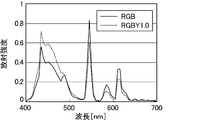
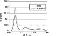
- FIG. 21 is a graph showing the relationship between the wavelength and the radiation intensity of a cold cathode tube provided in a conventional RGBY liquid crystal display device
- FIG. 22 shows the wavelength and radiation of an LED provided in a conventional RGBY liquid crystal display device. It is a graph which shows the relationship with an intensity
- FIG. 23 is a graph showing the relationship between the wavelength and the transmittance of the color filter included in the RGBY liquid crystal display device and the color filter included in the RGB liquid crystal display device.
- the color filter substrate included in the conventional RGBY liquid crystal display device is obtained by adding yellow to the conventional RGB color filter substrate. At this time, the white transmitted light of the color filter substrate included in the RGBY liquid crystal display device is shifted to the yellow side.
- the color temperature of the white transmitted light is set to the RGB type by using a backlight having an increased blue component spectrum as shown in FIGS. It was raised to about 12000K like the liquid crystal display device.
- the RGBY liquid crystal display device when the blue component is increased, the primary color luminance, particularly the red primary color luminance, is lowered.
- the saturation of red display also decreases. Further, as shown in FIG.
- the transmittance of the blue component is the same as that of the color filter included in the RGB liquid crystal display device, instead of the high transmittance of the red component. Compared to lower. Nonetheless, increasing the blue component of the backlight and decreasing the red component cannot effectively utilize the backlight light, and further increasing the blue component reduces the luminous efficiency of the light source, This will hinder low power consumption.
- the present invention has been made in view of the above-described situation, and a liquid crystal display device that suppresses a decrease in primary color luminance, a decrease in saturation, and an increase in power consumption when a color filter including at least four primary colors is used. It is intended to provide.
- the present inventors have made various studies on a liquid crystal display device using a color filter composed of at least four primary colors. For example, even in an RGBY liquid crystal display device, the color temperature thereof is the same as that of an RGB liquid crystal display device. Focusing on the fact that they are set equally, it has been found that this causes various problems as described above. In particular, paying attention to the color temperature of white light at the maximum output, the color temperature of white light at the maximum output of all the pixels is equivalent to that of the conventional RGB liquid crystal display device, thereby reducing the primary color luminance and saturation. It has been found that this has led to a decrease in power consumption and an increase in power consumption.
- the present invention is a liquid crystal display device including a color filter substrate in which at least four color filters are arranged for each pixel, and the liquid crystal display device has a color temperature of white light emitted from the display surface of less than 12000K.
- This is a liquid crystal display device.
- this liquid crystal display device is also referred to as a first liquid crystal display device of the present invention.
- color temperature refers to an absolute temperature (K) in the color of light emitted by an ideal object that completely absorbs energy called a black body (complete radiator).
- K an absolute temperature
- a change in the color of the light represented on the xy chromaticity diagram is called a black body locus.
- the white light can be indicated by the color temperature.
- the xy coordinates indicating white light are not on the black body locus and the deviation ( ⁇ uv) from the black body locus is between ⁇ 0.02 and +0.02, the temperature of the closest black body is expressed as “correlation color”.
- color temperature is 10000K means that the color temperature at the maximum output of all the pixels is 10000K. That is, it does not include the color temperature set to 10000K by the gradation setting.
- the color temperature is measured by a spectroradiometer installed in the vertical direction of the display surface of the liquid crystal display device.
- the configuration of the first liquid crystal display device of the present invention is not particularly limited by other components as long as such components are essential. A preferred embodiment of the first liquid crystal display device of the present invention will be described in detail below.
- the color temperature of white light emitted from the display surface is 10,000 K or less. Thereby, an increase in power consumption and a decrease in primary color luminance can be further suppressed.
- the color temperature is more preferably 4500K or more and 10,000K or less.
- the color filter substrate includes at least red, green, blue, and yellow color filters
- the liquid crystal display device has red, green, blue, and yellow openings.
- the above-mentioned opening is an exit of light from which the backlight light transmitted through the color filter is emitted to the outside.
- a red opening refers to the backlight light transmitted through the red color filter to the outside. It is the exit of light.
- red, green, blue, and yellow are defined as follows. That is, “red” means a color having a dominant wavelength of 595 nm to 650 nm, and preferably a color having a dominant wavelength of 600 nm to 640 nm. The red color purity is preferably 75% or more and 97% or less. Similarly, “green” refers to a color having a dominant wavelength of 490 nm to 555 nm, and preferably a color having a dominant wavelength of 510 nm to 550 nm. The green color purity is preferably 50% or more and 80% or less.
- Blue means a color having a dominant wavelength of 450 nm to 490 nm, and preferably a color having a dominant wavelength of 450 nm to 475 nm.
- the blue color purity is preferably 50% or more and 95% or less.
- the yellow color filter substrate of the present invention partially transmits the light in the red region and the light in the green region.
- Yellow means a color having a main wavelength of 560 to 580 nm. The color purity is preferably 85% or more and 97% or less.
- the area of the color filter refers to the area of the region through which the backlight is transmitted.
- the lightness of each primary color decreases.
- a reduction in the luminance of red light greatly impairs display quality.
- a reduction in blue light luminance also impairs display quality.
- a decrease in the brightness of green light hardly affects the display quality.
- yellow display since yellow display can be performed by emitting red light and green light to some extent in addition to yellow light, a decrease in yellow light luminance (yellow luminance) is also unlikely to affect display quality. . Therefore, it is possible to increase the luminance of a relatively low-luminance color by increasing the red and blue aperture areas, which can cause problems in image display due to low luminance. In this manner, a high quality image (video) can be displayed by increasing the aperture area of the color whose luminance decreases.
- the total area ratio may be derived from the total area in one pixel or may be derived from the total area in all pixels. Normally, since all the pixels have the same color filter configuration, they have the same value in any case.
- the red opening area can be increased, so that the red luminance can be further increased.
- the red opening area can be further increased, so that the red luminance can be further increased.
- the luminance of the white light is a color temperature emitted from a display surface of a three-color liquid crystal display device including a color filter substrate on which three-color filters of red, green, and blue are arranged at 12000K.
- the luminance of the three-color white light is 100%, it is preferably 100% or more. That is, the white luminance of the first liquid crystal display device of the present invention is preferably equal to or higher than the three-color white luminance of a conventional general RGB liquid crystal display device in which the color temperature of white light is 12000K. As a result, power consumption can be suppressed as compared with a conventional general RGB liquid crystal display device.
- the luminance is measured by a spectroradiometer installed in the vertical direction of the display surface of the liquid crystal display device.
- the luminance of red light (red luminance) emitted from the display surface of the liquid crystal display device is preferably 12% or more when the luminance of the white light is 100%. Thereby, it is possible to display a high-quality image (video) excellent in color development of red and red mixed colors. If the red luminance is less than 12%, the mixed color of red and red becomes black and the reproducibility is lowered. Further, the red luminance is more preferably 13% or more, and particularly preferably 15% or more.
- the luminance of green light (green luminance) emitted from the display surface of the liquid crystal display device is preferably 30% or more when the luminance of the white light is 100%. Thereby, it is possible to display a high-quality image (video) excellent in color development of green or a mixed color of green. When the green luminance is less than 30%, the green color or the mixed color of green becomes dark and the reproducibility is lowered.
- the luminance (blue luminance) of the blue light emitted from the display surface of the liquid crystal display device is preferably 8% or more, more preferably 10% or more when the luminance of the white light is 100%. preferable. Thereby, it is possible to display a high-quality image (video) excellent in color development of blue or a mixed color of blue.
- the blue luminance is less than 8%, the reproducibility of blue or a mixed color of blue is lowered. Even if the luminance of blue is lower than that of red or green, the color reproducibility is not affected because the blue color is difficult to look black and dark even when the luminance is low. .
- the present invention is also a liquid crystal display device including a color filter substrate in which color filters of at least three colors of red, green, and blue and other colors having higher brightness than the three colors are arranged for each pixel.
- the liquid crystal display device has a chromaticity (x, y) of white light emitted from the display surface of the liquid crystal display device in a range satisfying the following (1) to (4).
- the brightness of the white light is a three-color liquid crystal display device including a color filter substrate on which three color filters of red, green, and blue are arranged, and the three colors when the color temperature is 12000K. If the brightness of the system white light is 100%, it should be 100% or more.
- the luminance of red light (red luminance) emitted from the display surface of the liquid crystal display device is 12% or more when the luminance of the white light is 100%.
- the luminance of green light (green luminance) emitted from the display surface of the liquid crystal display device is 30% or more when the luminance of the white light is 100%.
- the luminance of blue light emitted from the display surface of the liquid crystal display device blue luminance is 8% or more when the luminance of the white light is 100%.
- this liquid crystal display device is also referred to as a second liquid crystal display device of the present invention. According to the second liquid crystal display device of the present invention, an increase in power consumption and a decrease in red luminance can be suppressed, and a high-quality image (video) can be displayed.
- the configuration of the second liquid crystal display device of the present invention is not particularly limited by other components as long as such components are essential. A preferred embodiment of the second liquid crystal display device of the present invention will be described in detail below.
- the other color is preferably yellow. Thereby, the reproducibility of the color of the yellow region and the color of the cyan region can be improved.
- liquid crystal display device of the present invention it is possible to provide a liquid crystal display device that suppresses a decrease in primary color luminance, a decrease in saturation, and an increase in power consumption.
- FIG. 2 is a plan view illustrating a schematic configuration of a TFT substrate in the liquid crystal display device according to Embodiment 1.
- FIG. 2 is a plan view illustrating a schematic configuration of a color filter substrate (counter substrate) in the liquid crystal display device according to Embodiment 1.
- FIG. 1 is a schematic cross-sectional view showing a liquid crystal display device according to Embodiment 1.
- FIG. 5 is a schematic cross-sectional view showing a liquid crystal display device according to Embodiment 2.
- FIG. 6 is a schematic cross-sectional view showing a liquid crystal display device according to Embodiment 3.
- FIG. 6 is a schematic cross-sectional view showing a liquid crystal display device according to Embodiment 4.
- FIG. 1 is a schematic cross-sectional view showing a liquid crystal display device according to Embodiment 1.
- FIG. 5 is a schematic cross-sectional view showing a liquid crystal display device according to Embodiment 2.
- FIG. 6 is a schematic cross-sectional view
- FIG. 6 is a schematic cross-sectional view showing a liquid crystal display device according to Embodiment 5.
- FIG. 7 is a schematic cross-sectional view showing a liquid crystal display device according to Embodiment 6.
- FIG. 10 is a schematic cross-sectional view showing a liquid crystal display device according to Embodiment 7.
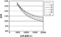
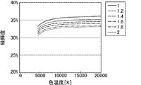
- FIG. 7 is a graph showing the relationship between the color temperature of white light and white luminance in the liquid crystal display devices of Embodiments 1 to 6.
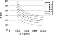
- 7 is a graph showing the relationship between the color temperature of white light and red luminance in the liquid crystal display devices of Embodiments 1 to 6.
- 7 is a graph showing the relationship between the color temperature of white light and green luminance in the liquid crystal display devices of Embodiments 1 to 6.
- 7 is a graph showing the relationship between the color temperature of white light and the blue luminance in the liquid crystal display devices of Embodiments 1 to 6.
- 7 is a graph showing red luminance (%) when the vertical axis is the aperture ratio and the horizontal axis is the color temperature of white light in the liquid crystal display devices of Embodiments 1 to 6.
- 7 is a graph showing white luminance (%) when the vertical axis is the aperture ratio and the horizontal axis is the color temperature of white light in the liquid crystal display devices of Embodiments 1 to 6.
- it is a graph which shows red luminance (%) when white luminance of white light shown by chromaticity (x, y) is set to 100%.
- Embodiment 8 it is a graph which shows the white brightness
- FIG. 20 is a graph obtained by superimposing FIGS.
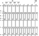
- FIG. 1 is a plan view showing a schematic configuration of a TFT substrate in the liquid crystal display device according to the first embodiment.
- the TFT substrate 200 has a matrix wiring made up of scanning lines 4 and signal lines 6 arranged on a glass substrate, and a thin film transistor (TFT) 8 is provided at each intersection of the matrix wirings.
- transparent electrodes 35 35R, 35G, 35B and 35Y
- transparent conductive material such as indium tin oxide (ITO)
- the gate electrode of the TFT 8 is connected to the scanning line 4, the source electrode is connected to the signal line 6, and the drain electrode is connected to the transparent electrode 35 via the drain lead wiring 9.
- the transparent electrodes 35R, 35G, 35B, and 35Y face red, green, blue, and yellow color filters 10R, 10G, 10B, and 10Y provided on a counter substrate 100 (to be described later) in the liquid crystal display device.
- the scanning lines 4 and the signal lines 6 are arranged so that the transparent electrodes 35R, 35G, 35B, and 35Y have the same size.
- the auxiliary capacitance wiring 7 for holding the voltage applied to the transparent electrode 35 is arranged in parallel with the scanning line 4.
- the auxiliary capacitance line 7 constitutes the auxiliary capacitance 3 by facing the end portion of the drain lead line 9 through the insulating film.
- FIG. 2 is a plan view illustrating a schematic configuration of a color filter substrate (counter substrate) in the liquid crystal display device according to the first embodiment.
- the counter substrate 100 has red, green, blue, and yellow color filters 10R, 10G, 10B, and 10Y arranged in stripes in this order, and a black matrix 10BM is arranged between the filters.
- the color filters 10R, 10G, 10B, and 10Y each select the color of light that passes through the color filters 10R, 10G, 10B, and 10Y.
- the red, green, and blue color filters 10R, 10G, and 10B mainly transmit the red component, the green component, and the blue component of the incident light, respectively.
- the yellow color filter 10Y includes the red component of the incident light.
- the color filters 10R, 10G, 10B, and 10Y are provided to face the transparent electrodes 35R, 35G, 35B, and 35Y provided on the TFT substrate 200 in the liquid crystal display device, respectively, and the black matrix 10BM is In the liquid crystal display device, it is provided so as to face the scanning line 4 and the signal line 6.
- the color filters 10R, 10G, 10B, and 10Y have the same area. That is, in the liquid crystal display device of Embodiment 1, the red, green, blue, and yellow opening areas are the same.
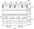
- FIG. 3 is a schematic cross-sectional view illustrating the liquid crystal display device according to the first embodiment.
- the liquid crystal display device 500 according to the first embodiment of the present invention has a configuration in which a liquid crystal layer 300 is sandwiched between the counter substrate 100 and the TFT substrate 200 described above.
- the counter substrate 100 includes a phase difference plate 22 and a polarizing plate 23 on the outer side (observation surface side) of the glass substrate 21, and red, green, blue, and yellow on the inner side (back side) of the glass substrate 21.
- the phase difference plate 22 adjusts the polarization state of light that passes through the retardation plate 22.
- the polarizing plate 23 transmits only light of a specific polarization component.
- the viewing angle compensation function is provided by adjusting the arrangement and configuration of the retardation film 22 and the polarizing plate 23.
- the overcoat layer 25 prevents contaminants from eluting into the liquid crystal layer 300 from the red, green, blue, and yellow filters 10R, 10G, 10B, and 10Y, and also planarizes the surface of the counter substrate 100.
- the counter electrode 26 is opposed to the transparent electrodes 35R, 35G, 35B, and 35Y provided on the TFT substrate 200 side through the liquid crystal layer 300, and drives the liquid crystal molecules by applying a voltage to the liquid crystal layer 300.
- Used for The counter electrode 26 is made of a transparent conductive material such as indium tin oxide (ITO).
- the alignment film 27 controls the alignment of liquid crystal molecules in the liquid crystal layer 300.
- the TFT substrate 200 includes a phase difference plate 32 and a polarizing plate 33 on the outer side (back side) of the glass substrate 31, and the thin film transistor (TFT) 8 and the interlayer on the inner side (observation side) of the glass substrate 31.
- An insulating film 34, a transparent electrode 35 (35R, 35G, 35B, and 35Y), an alignment film 38, and the like are provided.
- the phase difference plate 32 adjusts the polarization state of the light that passes through the retardation plate 32, as in the phase difference plate 22.
- the polarization plate 33 transmits only light of a specific polarization component, like the polarization plate 23. It is something to be made.
- the polarizing plate 33 is disposed so as to be optically orthogonal to the polarizing plate disposed on the counter substrate 100 side.
- the transparent electrode 35 (35R, 35G, 35B, and 35Y) is disposed for each color filter on the counter substrate 100 side, and drives the liquid crystal molecules by applying a voltage to the liquid crystal layer 300 for each color filter region. Similar to the alignment film 27, the alignment film 38 controls the alignment of liquid crystal molecules in the liquid crystal layer 300.
- a backlight 36 used for display is provided on the back side (back side) of the TFT substrate 200.
- the liquid crystal display device 500 according to the first embodiment includes the four color filters 10R, 10G, 10B, and 10Y of red, green, blue, and yellow.
- the liquid crystal display device 500 is red. , Green and blue color filters.
- the areas of the three color filters are formed to have the same size, and the liquid crystal display device of the comparative form 1 has red, green, and blue openings having the same area.
- the backlight is set so that the color temperature of the white light of the liquid crystal display device of comparative form 1 is 12000K. Except for the above differences, the liquid crystal display device of the comparative embodiment is the same as the liquid crystal display device 500 of the first embodiment.
- the color temperature of white light is changed to 4500K to 20000K, and the white luminance and the red luminance, green luminance, and blue luminance (%) when the white luminance is 100%.
- the white luminance is a liquid crystal display device having a color filter substrate in which three color filters of red, blue, and green are arranged, and a liquid crystal having a color temperature of emitted white light of 12000K. This is the luminance when the white luminance (three-color white luminance) of the display device is 100%.
- Table 1 The results are shown in Table 1.
- Example 1 in which the color temperature of white light is 4500K
- Example 2 in which the color temperature of white light is 5000K
- Example 3 in which the color temperature of white light is 5500K
- Example 3 color temperature of white light
- Example 5 in which the color temperature of white light is set to 6500K
- Example 6 in which the color temperature of white light is set to 7000K
- color temperature of white light is set to 7500K
- Example 7 with white light color temperature set at 8000K Example 8 with white light color temperature set at 9000K
- Example 9 with white light color temperature set at 10000K It was set to 10. Further, a white light color temperature of 12000K was set as Comparative Example 1, a white light color temperature of 15000K was set as Comparative Example 2, and a white light color temperature was set at 20000K as Comparative Example 3. .
- the color temperature and luminance were measured with an ultra-low luminance spectroradiometer SR-UL1 (Topcon Co., Ltd.) installed in the vertical direction of the display surface of the liquid crystal display device.
- white luminance and red luminance were improved by setting the color temperature of white light to 10,000 K or less. Accordingly, in the RGBY liquid crystal display device, red luminance can be improved and power consumption can be reduced.
- the blue luminance decreases when the color temperature of white light is set low, but even if the blue luminance decreases, the image quality is not greatly affected.
- the green luminance did not change greatly even when the color temperature of white light was set low.
- the red luminance is 12% or more
- the green luminance is 30% or more
- the blue luminance is 8% or more. Therefore, in the liquid crystal display device of Embodiment 1 in which red, green, blue, and yellow aperture areas are equal, the color temperature of white light is more preferably 5500K to 6500K (Examples 3 to 5).
- FIG. 4 is a schematic cross-sectional view illustrating the liquid crystal display device according to the second embodiment.
- the liquid crystal display device 500 of the first embodiment red, green, blue, and yellow opening areas are formed to have the same size, but the liquid crystal display device 510 of the second embodiment has a configuration as shown in FIG.
- the total area of the color filters 10R and 10B is 1.2 times that of the color filters 10G and 10Y, and the total area ratio of the red and blue openings is 1.2 times the total area ratio of the green and yellow openings.
- the liquid crystal display device 510 of the second embodiment is the same as the liquid crystal display device 500 of the first embodiment.
- the color temperature of white light is changed to 4500K to 20000K, and the white luminance, red luminance, green luminance, and blue luminance (%) when the white luminance is 100%.
- the white luminance is a liquid crystal display device having a color filter substrate on which three color filters of red, blue, and green are arranged, and the color temperature of the emitted white light is 12000K. This is the luminance when the white luminance (three-color white luminance) is 100%.
- Table 2 The results are shown in Table 2.
- a white light color temperature of 12000K was set as Comparative Example 4
- a white light color temperature of 15000K was set as Comparative Example 5
- a white light color temperature was set at 20000K as Comparative Example 6. .
- the color temperature and luminance were measured with an ultra-low luminance spectroradiometer SR-UL1 (Topcon Co., Ltd.) installed in the vertical direction of the display surface of the liquid crystal display device.
- white luminance and red luminance were improved by setting the color temperature of white light to 10000K or lower. Accordingly, in the RGBY liquid crystal display device, red luminance can be improved and power consumption can be reduced.
- the blue luminance decreases when the color temperature of white light is set low, but even if the blue luminance decreases, the image quality is not greatly affected.
- the green luminance did not change greatly even when the color temperature of white light was set low.
- the red luminance is 12% or more
- the green luminance is 30% or more
- the blue luminance is 8% or more. Therefore, in the liquid crystal display device of the second embodiment, it is more preferable that the color temperature of white light is 5000 K to 10,000 K (Examples 12 to 20).
- the total area ratio of the red and blue openings is 1.2 times the total area ratio of the green and yellow openings, so that the red color is further red than the liquid crystal display device of the first embodiment. It has been found that the brightness can be improved.
- FIG. 5 is a schematic cross-sectional view illustrating the liquid crystal display device according to the third embodiment.
- the color filters 10R, 10G, 10B, and 10Y have the same area, but the liquid crystal display device 520 according to the third embodiment has a color filter as shown in FIG.
- the total area of the filters 10R and 10B is 1.4 times that of the color filters 10G and 10Y, and the total area ratio of the red and blue openings is 1.4 times the total area ratio of the green and yellow openings.
- the liquid crystal display device 520 of the third embodiment is the same as the liquid crystal display device 500 of the first embodiment.
- the color temperature of white light is changed to 4500K to 20000K, and the white luminance, red luminance, green luminance, and blue luminance (%) when the white luminance is set to 100%.
- the white luminance is a liquid crystal display device having a color filter substrate in which three color filters of red, blue, and green are arranged, and a liquid crystal having a color temperature of emitted white light of 12000K. This is the luminance when the white luminance of the display device is 100%.
- Table 3 The results are shown in Table 3.
- Example 21 in which the color temperature of white light is 4500K
- Example 22 in which the color temperature of white light is 5000K
- Example 23 in which the color temperature of white light is 5500K
- Example 23 color temperature of white light In which the color temperature of white light was set to 6500K
- Example 25 in which the color temperature of white light was 6500K
- Example 26 in which the color temperature of white light was set to 7000K
- the color temperature of white light was set to 7500K
- Example 27 Example 28 with white light color temperature set at 8000K
- Example 29 with white light color temperature set at 9000K
- Example with white light color temperature set at 10000K 30 Example 21 in which the color temperature of white light is 4500K
- Example 22 in which the color temperature of white light is 5000K
- Example 23 in which the color temperature of white light is 5500K
- Example 23 color temperature of white light In which the color temperature of white light was set to 6500K
- Example 25 in which the color temperature of white light was 6500K
- Example 26 in which the color
- a white light having a color temperature of 12000K is a comparative example 7
- a white light having a color temperature of 15000K is a comparative example 8
- a white light having a color temperature of 20000K is a comparative example 9. .
- the color temperature and luminance were measured with an ultra-low luminance spectroradiometer SR-UL1 (Topcon Co., Ltd.) installed in the vertical direction of the display surface of the liquid crystal display device.
- white luminance and red luminance were improved by setting the color temperature of white light to 10,000 K or less. Accordingly, in the RGBY liquid crystal display device, red luminance can be improved and power consumption can be reduced.
- the blue luminance decreases when the color temperature of white light is set low, but even if the blue luminance decreases, the image quality is not greatly affected.
- the green luminance did not change greatly even when the color temperature of white light was set low.
- the red luminance is 12% or more
- the green luminance is 30% or more
- the blue luminance is 8% or more.
- the color temperature of white light is The above conditions were satisfied at 4500K to 10000K (Examples 21 to 30). The above conditions are satisfied when the color temperature of white light is 12000K and 15000K (Comparative Examples 7 and 8), but the red luminance and white luminance are lower than when the color temperature of white light is 4500K to 10000K. Was.
- the total area ratio of the red and blue openings is 1.4 times the total area ratio of the green and yellow openings, so that the red color is further red than the liquid crystal display device of the second embodiment. It has been found that the brightness can be improved.
- FIG. 6 is a schematic cross-sectional view illustrating the liquid crystal display device according to the fourth embodiment.
- the color filters 10R, 10G, 10B, and 10Y have the same area, but the liquid crystal display device 530 of the second embodiment has a color filter as shown in FIG.
- the total area of the filters 10R and 10B is 1.6 times that of the color filters 10G and 10Y, and the total area ratio of the red and blue openings is 1.6 times the total area ratio of the green and yellow openings.
- the liquid crystal display device 530 of the fourth embodiment is the same as the liquid crystal display device 500 of the first embodiment.
- the color temperature of white light is changed to 4500K to 20000K, and the white luminance, red luminance, green luminance, and blue luminance (%) when the white luminance is set to 100%.
- the white luminance is a liquid crystal display device having a color filter substrate in which three color filters of red, blue, and green are arranged, and a liquid crystal having a color temperature of emitted white light of 12000K. This is the luminance when the white luminance (three-color white luminance) of the display device is 100%.
- Table 4 The results are shown in Table 4.
- a white light color temperature of 4500K is Example 31, a white light color temperature of 5000K is Example 32, a white light color temperature of 5500K is Example 33, and a white light color temperature is In which the color temperature of white light was set to 6500K, Example 35 in which the color temperature of white light was set to 6500K, Example 36 in which the color temperature of white light was set to 7000K, and color temperature of white light was set to 7500K Example 37, Example 38 with white light color temperature set at 8000K, Example 39 with white light color temperature set at 9000K, and Example with white light color temperature set at 10000K 40.
- a white light having a color temperature of 12000K is comparative example 10
- a white light having a color temperature of 15000K is comparative example 11
- a white light having a color temperature of 20000K is comparative example 12. .
- the color temperature and luminance were measured with an ultra-low luminance spectroradiometer SR-UL1 (Topcon Co., Ltd.) installed in the vertical direction of the display surface of the liquid crystal display device.
- white luminance and red luminance were improved by setting the color temperature of white light to 10000K or lower. Accordingly, in the RGBY liquid crystal display device, red luminance can be improved and power consumption can be reduced.
- the blue luminance decreases when the color temperature of white light is set low, but even if the blue luminance decreases, the image quality is not greatly affected.
- the green luminance did not change greatly even when the color temperature of white light was set low.
- the red luminance is 12% or more, the green luminance is 30% or more, and the blue luminance is 8% or more.
- the color temperature of white light is The above conditions were satisfied at 4500K to 10000K (Examples 31 to 40). The above conditions are also satisfied when the color temperature of white light is 12000K to 20000K (Comparative Examples 10 to 12), but the red luminance and white luminance are lower than when the color temperature of white light is 4500K to 10000K. Was. Further, from the viewpoint of image quality, it is particularly preferable that the red luminance is 15% or more, the green luminance is 30% or more, and the blue luminance is 10% or more. However, in the liquid crystal display device of Embodiment 4, the color of white light The above conditions were satisfied when the temperature was 7000 K (Example 36).
- the total area ratio of the red and blue openings is 1.6 times the total area ratio of the green and yellow openings. It has been found that the brightness can be improved.
- FIG. 7 is a schematic cross-sectional view illustrating the liquid crystal display device according to the fifth embodiment.
- the color filters 10R, 10G, 10B, and 10Y have the same area, but the liquid crystal display device 540 of the fifth embodiment has a color filter as shown in FIG.
- the total area of the filters 10R and 10B is 1.8 times that of the color filters 10G and 10Y, and the total area ratio of the red and blue openings is 1.8 times the total area ratio of the green and yellow openings.
- the liquid crystal display device 540 of the fifth embodiment is the same as the liquid crystal display device 500 of the first embodiment.
- the color temperature of white light is changed to 4500K to 20000K, and the white luminance, red luminance, green luminance, and blue luminance (%) when the white luminance is 100%.
- the white luminance is a liquid crystal display device having a color filter substrate in which three color filters of red, blue, and green are arranged, and a liquid crystal having a color temperature of emitted white light of 12000K. This is the luminance when the white luminance (three-color white luminance) of the display device is 100%.
- Table 5 The results are shown in Table 5.
- a white light color temperature of 12000K was set as Comparative Example 13
- a white light color temperature of 15000K was set as Comparative Example 14
- a white light color temperature was set at 20000K as Comparative Example 15. .
- the color temperature and luminance were measured with an ultra-low luminance spectroradiometer SR-UL1 (Topcon Co., Ltd.) installed in the vertical direction of the display surface of the liquid crystal display device.
- white luminance and red luminance were improved by setting the color temperature of white light to 10,000 K or less. Accordingly, in the RGBY liquid crystal display device, red luminance can be improved and power consumption can be reduced.
- the blue luminance decreases when the color temperature of white light is set low, but even if the blue luminance decreases, the image quality is not greatly affected.
- the green luminance did not change greatly even when the color temperature of white light was set low.
- the red luminance is 12% or more, the green luminance is 30% or more, and the blue luminance is 8% or more.
- the color temperature of white light is The above conditions were satisfied at 4500K to 10000K (Examples 41 to 50). The above conditions are also satisfied when the color temperature of white light is 12000K to 20000K (Comparative Examples 13 to 15), but the red luminance and white luminance are lower than when the color temperature of white light is 4500K to 10000K. Was. Further, from the viewpoint of image quality, it is particularly preferable that the red luminance is 15% or more, the green luminance is 30% or more, and the blue luminance is 10% or more. However, in the liquid crystal display device of Embodiment 5, the color of white light The above conditions were satisfied when the temperature was 6000 K to 9000 K (Examples 44 to 49).
- the total area ratio of the red and blue openings is 1.8 times the total area ratio of the green and yellow openings, so that the liquid crystal display device of the fourth embodiment is more than the liquid crystal display device of the fourth embodiment. Further, it has been found that the red luminance can be improved.
- FIG. 8 is a schematic cross-sectional view illustrating the liquid crystal display device according to the sixth embodiment.
- the color filters 10R, 10G, 10B, and 10Y have the same area, but the liquid crystal display device 550 of the sixth embodiment has a color display as shown in FIG.
- the total area of the filters 10R and 10B is 2.0 times that of the color filters 10G and 10Y, and the total area ratio of the red and blue openings is 2.0 times the total area ratio of the green and yellow openings.
- the liquid crystal display device 550 of the sixth embodiment is the same as the liquid crystal display device 500 of the first embodiment.
- the color temperature of white light is changed to 4500K to 20000K, white luminance, and red luminance, green luminance, and blue luminance (%) when the white luminance is 100%.
- the white luminance is a liquid crystal display device having a color filter substrate in which three color filters of red, blue, and green are arranged, and a liquid crystal having a color temperature of emitted white light of 12000K. This is the luminance when the white luminance (three-color white luminance) of the display device is 100%.
- Table 6 The results are shown in Table 6.
- a white light color temperature of 4500K is Example 51
- a white light color temperature of 5000K is Example 52
- a white light color temperature of 5500K is Example 53
- a white light color temperature is In which the color temperature of white light was set to 6500K
- Example 55 in which the color temperature of white light was 6500K
- Example 56 in which the color temperature of white light was set to 7000K
- the color temperature of white light was set to 7500K
- Example 59 with white light color temperature set at 9000K is Example with white light color temperature set at 10000K 60.
- a white light having a color temperature of 12000K is a comparative example 16
- a white light having a color temperature of 15000K is a comparative example 17
- a white light having a color temperature of 20000K is a comparative example 18.
- the color temperature and luminance were measured with an ultra-low luminance spectroradiometer SR-UL1 (Topcon Co., Ltd.) installed in the vertical direction of the display surface of the liquid crystal display device.
- white luminance and red luminance were improved by setting the color temperature of white light to 10000K or lower. Accordingly, in the RGBY liquid crystal display device, red luminance can be improved and power consumption can be reduced.
- the blue luminance decreases when the color temperature of white light is set low, but even if the blue luminance decreases, the image quality is not greatly affected.
- the green luminance did not change greatly even when the color temperature of white light was set low.
- the red luminance is 12% or more, the green luminance is 30% or more, and the blue luminance is 8% or more.
- the color temperature of white light is The above conditions were satisfied at 4500K to 10000K (Examples 51 to 60). The above conditions are also satisfied when the color temperature of white light is 12000K to 20000K (Comparative Examples 16 to 18), but the red luminance and white luminance are lower than when the color temperature of white light is 4500K to 10000K. Was. Further, from the viewpoint of image quality, it is particularly preferable that the red luminance is 15% or more, the green luminance is 30% or more, and the blue luminance is 10% or more. However, in the liquid crystal display device of Embodiment 5, the color of white light The above conditions were satisfied when the temperature was 6000 K to 10000 K (Examples 54 to 60).
- the total area ratio of the red and blue openings is 2.0 times the total area ratio of the green and yellow openings, so that the red color is further red than the liquid crystal display device of the fifth embodiment. It has been found that the brightness can be improved.
- FIG. 9 is a schematic cross-sectional view illustrating the liquid crystal display device according to the seventh embodiment.
- the color filters 10R, 10G, 10B, and 10Y have the same area, but the liquid crystal display device 600 according to the seventh embodiment has a color filter as shown in FIG.
- the total area of the filters 10R and 10B is 2.2 times that of the color filters 10G and 10Y, and the total area ratio of the red and blue openings is 2.2 times the total area ratio of the green and yellow openings.
- the liquid crystal display device 600 of the seventh embodiment is the same as the liquid crystal display device 500 of the first embodiment.
- the color temperature of white light is changed to 4500K to 20000K, white luminance, and red luminance, green luminance, and blue luminance (%) when the white luminance is 100%.
- the white luminance is a liquid crystal display device having a color filter substrate in which three color filters of red, blue, and green are arranged, and a liquid crystal having a color temperature of emitted white light of 12000K. This is the luminance when the white luminance of the display device is 100%.
- Table 7 The results are shown in Table 7.
- a white light color temperature of 4500K was Example 61, a white light color temperature of 5000K was Example 62, a white light color temperature of 5500K was Example 63, and a white light color temperature was In which the color temperature of white light was set to 6500K, Example 65 in which the color temperature of white light was 6500K, Example 66 in which the color temperature of white light was set to 7000K, and the color temperature of white light was set to 7500K Example 67, Example 68 with white light color temperature set at 8000K, Example 69 with white light color temperature set at 9000K, and Example with white light color temperature set at 10000K 70.
- a white light color temperature of 12000 K was set as Comparative Example 19
- a white light color temperature of 15000 K was set as Comparative Example 20
- a white light color temperature was set at 20000 K as Comparative Example 21. .
- the color temperature and luminance were measured with an ultra-low luminance spectroradiometer SR-UL1 (Topcon Co., Ltd.) installed in the vertical direction of the display surface of the liquid crystal display device.
- the red luminance is 12% or more
- the green luminance is 30% or more
- the blue luminance is 8% or more.
- the color temperature of white light is The above conditions were satisfied at 4500K to 20000K (Examples 61 to 70 and Comparative Examples 19 to 21).
- display unevenness and display roughness were observed. This is because the red and blue aperture areas are 2.2 times larger than the green and yellow aperture areas, and the non-uniformity of the pixel capacitance increases, causing display unevenness, and the red and blue aperture areas. By increasing the area, the entire pixel becomes larger, so the display is considered rough.
- FIG. 10 is a graph showing the relationship between the color temperature of white light and the white luminance in the liquid crystal display devices of Embodiments 1 to 6, and FIG. 11 is the color temperature of white light in the liquid crystal display devices of Embodiments 1 to 6. It is a graph which shows the relationship between red brightness.
- FIG. 12 is a graph showing the relationship between the color temperature of white light and the green luminance in the liquid crystal display devices of Embodiments 1 to 6, and
- FIG. 13 is a graph of white light in the liquid crystal display devices of Embodiments 1 to 6.
- the total area ratio of the red and blue apertures As shown in Examples 61 to 70 of Embodiment 7, from the viewpoint of improving the red luminance, the larger the total area ratio of the red and blue apertures, the better the result. If the total area ratio of the blue openings is too large, display unevenness and display roughness may occur. From the above, the total area ratio of the red and blue openings is preferably 1.2 times or more and 2 times or less, and 1.8 times or less of the total area ratio of the green and yellow openings. Is more preferable.
- FIG. 14 is a graph showing red luminance (%) when the vertical axis is the aperture ratio and the horizontal axis is the color temperature of white light in the liquid crystal display devices of Embodiments 1 to 6.
- An opening ratio of 1.2 in the graph means that the total area ratio (RB) of the red and blue openings is 1.2 times the total area ratio (GY) of the green and yellow openings.
- the red luminance can be improved by increasing the aperture ratio, that is, by increasing RB.
- the red luminance can be improved by lowering the color temperature of white light.
- FIG. 15 is a graph showing white luminance (%) when the vertical axis represents the aperture ratio and the horizontal axis represents the color temperature of white light in the liquid crystal display devices of Embodiments 1 to 6. As shown in FIG. 15, white luminance can be significantly improved by lowering the color temperature of white light. Further, white luminance can be improved by increasing the aperture ratio, that is, by increasing RB.
- the chromaticity of white light is indicated by the color temperature (or correlated color temperature), but in the eighth embodiment, the chromaticity of white light is not indicated by the color temperature. That is, the chromaticity of white light is not set on black body radiation or in the vicinity of black body radiation. Otherwise, the liquid crystal display device of the eighth embodiment is the same as the liquid crystal display device of the fourth embodiment, and the liquid crystal display device of the eighth embodiment has a total area of the color filters 10R and 10B of 1. The total area ratio of the red and blue openings is 1.6 times the total area ratio of the green and yellow openings.
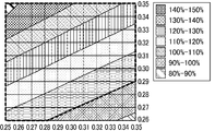
- FIG. 16 is a graph showing red luminance (%) when white luminance of white light indicated by chromaticity (x, y) is 100% in the eighth embodiment.
- the red luminance needs to be 12% or more.
- the chromaticity (x, y) of white light is present in the region surrounded by the thick line in FIG. % Or more.
- FIG. 17 shows a liquid crystal display device having a color filter substrate in which three color filters of red, blue, and green are arranged in Embodiment 8, and the color temperature of the emitted white light is 12000K.
- the white luminance needs to be 100% or more.
- the chromaticity (x, y) of white light exists in the area surrounded by the broken line in FIG. % Or more.
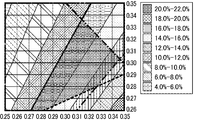
- FIG. 18 is a graph showing blue luminance (%) when white luminance of white light indicated by chromaticity (x, y) is 100% in the eighth embodiment.
- the blue luminance needs to be 8% or more.
- the chromaticity (x, y) of white light exists in the area surrounded by the one-dot chain line in FIG. 8% or more.
- FIG. 19 is a graph showing green luminance (%) when white luminance of white light indicated by chromaticity (x, y) is 100% in the eighth embodiment.
- the green luminance needs to be 30% or more.
- the chromaticity (x, y) of white light exists in the area surrounded by the two-dot chain line in FIG. 30% or more.
- FIG. 20 is a graph obtained by superimposing FIGS.
- the red luminance is 12% or more
- the white luminance is 100% or more
- the blue luminance is 8% or more
- the green luminance is 30% or more compared with the white luminance of the comparative form 1, thereby improving the red luminance.
- low power consumption can be achieved.
- Auxiliary capacitor 4 Scan line 6: Signal line 7: Auxiliary capacitance wiring 8: TFT 9: Drain lead wiring 10R: Red filter 10G: Green filter 10B: Blue filter 10Y: Yellow filter 10BM: Black matrix 21, 31: Glass substrate 22, 32: Phase difference plate 23, 33: Polarizing plate 25: Overcoat layer 26 : Counter electrode 27, 38: alignment film 34: interlayer insulating film 35: transparent electrode 36: backlight 100: counter substrate 200: TFT substrate 300: liquid crystal layer 500, 510, 520, 530, 540, 550, 600: liquid crystal display apparatus
Landscapes
- Physics & Mathematics (AREA)
- General Physics & Mathematics (AREA)
- Optics & Photonics (AREA)
- Nonlinear Science (AREA)
- Mathematical Physics (AREA)
- Chemical & Material Sciences (AREA)
- Crystallography & Structural Chemistry (AREA)
- Liquid Crystal (AREA)
- Optical Filters (AREA)
Abstract
本発明は、原色輝度の低下や彩度の低下、及び、消費電力の上昇を抑制する液晶表示装置を提供する。本発明は、少なくとも4色のカラーフィルタが画素毎に配置されたカラーフィルタ基板を備える液晶表示装置であって、該液晶表示装置は、表示面から射出される白色光の色温度が12000K未満である液晶表示装置である。
Description
本発明は、液晶表示装置に関する。より詳しくは、少なくとも4色のカラーフィルタが画素毎に配置されたカラーフィルタ基板を備える液晶表示装置に関するものである。
液晶表示装置は、薄型化及び低消費電力化が容易であり、また、小型から大型までの幅広い画面サイズに適用が可能であるといった液晶表示装置の本来的な利点に加え、近年では需要の急増とともに表示性能や機能性が大きく向上し、更なる高付加価値化が進められている。このような液晶表示装置は、ディスプレイ分野のあらゆる形態において、例えば、テレビジョン、パソコン用ディスプレイ、携帯端末用ディスプレイ等の幅広い用途に利用が拡大している。
従来の液晶表示装置としては、色表示における基本的な技術として3原色を用いる、赤色、緑色、及び、青色のカラーフィルタ基板を備えた液晶表示装置(以下では、RGB方式の液晶表示装置ともいう。)が一般的であった。
これに対して近年では、例えば、更に黄色のカラーフィルタ基板を備えた液晶表示装置(以下では、RGBY方式の液晶表示装置ともいう。)等、4色以上のいわゆる多原色カラーフィルタ基板を備えた多原色液晶表示装置(例えば、特許文献1~3)が開発され、これまでに表示できなかった色再現範囲を達成する等、種々の優れた表示性能が注目されている。
これに対して近年では、例えば、更に黄色のカラーフィルタ基板を備えた液晶表示装置(以下では、RGBY方式の液晶表示装置ともいう。)等、4色以上のいわゆる多原色カラーフィルタ基板を備えた多原色液晶表示装置(例えば、特許文献1~3)が開発され、これまでに表示できなかった色再現範囲を達成する等、種々の優れた表示性能が注目されている。
RGB方式の液晶表示装置、例えば、RGB方式の液晶表示装置からなるテレビジョンにおいては、通常、表示される白色光の色温度が12000~15000Kに設定されている。これは、白色光の色温度を12000Kよりも低くすると、蛍光灯等の照明下では、観察者の心理的に画像が黄色味を帯びているように感じられるからである。また、もともとは、これまで用いられてきたブラウン管使用のテレビジョンにおいてそのように設定されてきたことによる。なお、上記テレビジョンにおいては、白青色光の出力を抑えることで白色光の色温度を低下させるシネマモードと呼ばれるような階調設定手段を備えることも知られている。
従来の多原色液晶表示装置からなるテレビジョンにおいても、RGB方式の液晶表示装置からなるテレビジョンと同様に、白色光の色温度は12000~15000Kに設定されている。このように、多原色液晶表示装置従来の設定を踏襲するという考え方が一般的である。しかしながら、多原色液晶表示装置と従来のRGB方式の液晶表示装置との表示特性上の最も大きな違いは、原色の明度が異なることであり、この原色の明度は、白表示の色度設定に影響され、特に、各原色サブ画素間の開口比率と白表示の色度設定で大きく変化するが、この点について検討されていることはなかった。多原色液晶表示装置においては、白色光の色温度を12000~15000Kにすると、以下の理由から、消費電力の上昇、及び、原色輝度の低下を招来してしまう点で改善の余地があった。
図21~図23を用いて、RGBY方式の液晶表示装置を例に、白色光の色温度を12000~15000Kとすると消費電力の上昇や原色輝度の低下等を招来してしまう理由について詳述する。図21は、従来のRGBY方式の液晶表示装置が備える冷陰極管の波長と放射強度との関係を示すグラフであり、図22は、従来のRGBY方式の液晶表示装置が備えるLEDの波長と放射強度との関係を示すグラフである。なお、図21及び図22が示す液晶表示装置において、赤色、緑色、青色、及び黄色の開口面積は等しい。図23は、RGBY方式の液晶表示装置が備えるカラーフィルタとRGB方式の液晶表示装置が備えるカラーフィルタとにおける波長と透過率の関係を示すグラフである。
従来のRGBY方式の液晶表示装置が備えるカラーフィルタ基板は、従来のRGB方式のカラーフィルタ基板に黄色を追加したものである。このとき、RGBY方式の液晶表示装置が備えるカラーフィルタ基板の白色透過光は黄色側にシフトする。これを補正するために、従来のRGBY方式の液晶表示装置においては、図17及び図18に示すように青成分のスペクトルが増加されたバックライトを用いて、白色透過光の色温度をRGB方式の液晶表示装置と同様に12000K程度まで上げていた。しかし、RGBY方式の液晶表示装置において、青成分を増加させると、原色輝度、特に赤の原色輝度が低下してしまう。また、色度が白色寄りにシフトすることで、赤表示の彩度も低下してしまう。更に、図19に示すように、RGBY方式の液晶表示装置が備えるカラーフィルタにおいては、赤成分の透過率が高い代わりに、青成分の透過率は、RGB方式の液晶表示装置が備えるカラーフィルタに比べ、低くなっている。にもかかわらず、バックライトの青成分を増加させ、赤成分を減少させるのは、バックライト光を有効活用することができず、更に青成分が増加することにより光源の発光効率が低下し、低電力化の妨げとなってしまう。
このように、従来のRGBY方式の液晶表示装置においては、白色光の色温度を12000~15000Kとすると消費電力の上昇や赤輝度の低下による表示品位の低下を招来してしまうという課題があった。
本発明は、上記現状に鑑みてなされたものであり、少なくとも4原色からなるカラーフィルタを用いる場合に、原色輝度の低下や彩度の低下、及び、消費電力の上昇を抑制する液晶表示装置を提供することを目的とするものである。
本発明者らは、少なくとも4原色からなるカラーフィルタを用いる液晶表示装置について種々検討したところ、例えば、RGBY方式の液晶表示装置であってもその色温度がRGB方式の液晶表示装置の色温度と等しく設定されていることに着目し、そのために上述したような種々の課題が生じることを見いだした。特に、最大出力時の白色光の色温度に着目し、全画素の最大出力時の白色光の色温度が従来のRGB方式の液晶表示装置と同等であることにより、原色輝度の低下や彩度の低下、及び、消費電力の上昇を招来しているということを見いだしたものである。そして、白色光の色温度を下げることにより、特に、全画素の最大出力時の白色光の色温度を特定値より低く設定することによって、多くの光学特性が改善することが判明し、また上記課題をみごとに解決することができることに想到し、本発明に到達したものである。
すなわち、本発明は少なくとも4色のカラーフィルタが画素毎に配置されたカラーフィルタ基板を備える液晶表示装置であって、該液晶表示装置は、表示面から射出される白色光の色温度が12000K未満である液晶表示装置である。この液晶表示装置を以下では、本発明の第1の液晶表示装置ともいう。
本明細書において「色温度」とは、黒体(完全放射体)というエネルギーを完全に吸収する理想的な物体が発する光の色における絶対温度(K)をいう。この光の色の変移をxy色度図上で表したものを黒体軌跡という。白色光を示すxy座標が黒体軌跡上にあるとき、白色光を色温度で示すことができる。また、白色光を示すxy座標が黒体軌跡上になく、黒体軌跡から偏差(Δuv)が-0.02~+0.02の間にある場合、最も近似の黒体の温度を「相関色温度」というが、本発明においては、例えば、「白色光の相関色温度が10000K」である場合についても、「白色光の色温度が10000K」という。また、本発明において「色温度が10000K」とは、全画素の最大出力時の色温度が10000Kのことをいう。すなわち、階調設定により、色温度を10000Kとしたものは含まない。
本発明において、色温度は、液晶表示装置の表示面の鉛直方向に設置された分光放射計によって測定される。
本発明の第1の液晶表示装置の構成としては、このような構成要素を必須として形成されるものである限り、その他の構成要素により特に限定されるものではない。
本発明の第1の液晶表示装置における好ましい形態について以下に詳しく説明する。
本発明の第1の液晶表示装置における好ましい形態について以下に詳しく説明する。
上記液晶表示装置は、表示面から射出される白色光の色温度が10000K以下であることが好ましい。これにより、消費電力の上昇や原色輝度の低下をより抑制できる。また、上記色温度は、4500K以上10000K以下であることがより好ましい。
上記カラーフィルタ基板は、少なくとも、赤色、緑色、青色、及び、黄色のカラーフィルタからなり、前記液晶表示装置は、赤色、緑色、青色、及び、黄色の開口を有することが好ましい。これにより、黄色領域の色、及び、シアン領域の色の再現性を高めることができる。上記開口とは、カラーフィルタを透過したバックライト光が外部に射出される光の出口のことであり、例えば、赤色の開口とは、赤色のカラーフィルタを透過したバックライト光が外部に射出される光の出口のことである。
なお、本発明において、赤色、緑色、青色、及び、黄色は、次のように定義される。すなわち、「赤色」とは、主波長が595nm以上650nm以下の色をいい、好ましくは、主波長が600nm以上640nm以下の色をいう。赤色の色純度は75%以上97%以下であることが好ましい。同様に、「緑色」とは、主波長が490nm以上555nm以下の色をいい、好ましくは、主波長が510nm以上550nm以下の色をいう。緑色の色純度は50%以上80%以下であることが好ましい。「青色」とは、主波長が450nm以上490nm以下の色をいい、好ましくは、主波長が450nm以上475nm以下の色をいう。青色の色純度は50%以上95%以下であることが好ましい。一方、本発明の黄色のカラーフィルタ基板は、赤領域の光と緑領域の光を部分的に透過させるものであり、「黄色」とは、主波長が560~580nmの色をいい、黄色の色純度が85%以上97%以下であることが好ましい。
上記液晶表示装置は、赤色及び青色の開口の合計面積比率をRBとし、緑色及び黄色の開口の合計面積比率をGYとすると、RB>GYであることが好ましい。本発明において、カラーフィルタの面積とはバックライト光が透過する領域の面積をいう。前述の通り多原色表示装置では、各原色の明度が低下する。特に、赤色光の輝度(赤輝度)の低下は表示品位を大きく損なってしまう。また、青色光の輝度(青輝度)の低下も表示品位を損なう。一方、緑色光の輝度(緑輝度)の低下は、表示品位に影響を与えにくい。また、黄色表示時には、黄色光に加え、赤色光及び緑色光をある程度発することにより黄色表示を行うことができるため、黄色光の輝度(黄輝度)の低下もまた、表示品位に影響を与えにくい。したがって、輝度が低くなることで画像表示に問題が生じ得る赤色及び青色の開口面積を大きくすることにより、相対的に輝度が低い色の輝度を高めることが可能となる。このように、輝度が低くなる色の開口面積を大きくすることで、良質な画像(映像)を表示することができる。なお、合計面積比率は、一つの画素における合計面積から導かれてもよいし、全ての画素における合計面積から導かれてもよい。通常では、全ての画素において同じカラーフィルタの構成となるため、いずれであっても同じ値となる。
上記液晶表示装置は、RB:GY=1.6:1.0であることが好ましい。これにより、赤色の開口面積をより大きくすることが可能となるため、赤輝度をより高めることが可能となる。
上記液晶表示装置は、RB:GY=2.0:1.0 であることが好ましい。これにより、赤色の開口面積をより一層大きくすることが可能となるため、赤輝度をより一層高めることが可能となる。
上記白色光の輝度(白輝度)は、赤色、緑色、及び、青色の3色カラーフィルタが配置されたカラーフィルタ基板を備える3色系液晶表示装置の表示面から射出される色温度が12000Kのときの3色系白色光の輝度を100%とすると、100%以上であることが好ましい。すなわち、本発明の第1の液晶表示装置の白輝度は、白色光の色温度が12000Kである従来の一般的なRGB方式の液晶表示装置の3色系白輝度以上であることが好ましい。これにより、従来の一般的なRGB方式の液晶表示装置に比べ、消費電力を抑えることが可能となる。
本発明において、輝度は、液晶表示装置の表示面の鉛直方向に設置された分光放射計によって測定される。
上記液晶表示装置の表示面から射出される赤色光の輝度(赤輝度)は、上記白色光の輝度を100%としたとき、12%以上であることが好ましい。これにより、赤色や赤色の混合色の発色に優れた良質な画像(映像)を表示することができる。赤輝度が12%未満となると、赤色や赤色の混合色がどす黒くなり、再現性が低下する。また、赤輝度は、13%以上であることがより好ましく、15%以上であることが特に好ましい。
上記液晶表示装置の表示面から射出される緑色光の輝度(緑輝度)は、上記白色光の輝度を100%としたとき、30%以上であることが好ましい。これにより、緑色や緑色の混合色の発色に優れた良質な画像(映像)を表示することができる。緑輝度が30%未満となると、緑色や緑色の混合色がどす黒くなり、再現性が低下する。
上記液晶表示装置の表示面から射出される青色光の輝度(青輝度)は、上記白色光の輝度を100%としたとき、8%以上であることが好ましく、10%以上であることがより好ましい。これにより、青色や青色の混合色の発色に優れた良質な画像(映像)を表示することができる。青輝度が8%未満となると、青色や青色の混合色の再現性が低下する。青の輝度が、赤や緑の輝度に比べ低めでも色の再現性に影響が出ないのは、青系統の色は、低輝度であっても視覚的にどす黒く見えづらく、濃く見えるためである。
本発明はまた、少なくとも、赤色、緑色、及び、青色の3色に加え、該3色よりも明度の高い他の色のカラーフィルタが画素毎に配置されたカラーフィルタ基板を備える液晶表示装置であって、該液晶表示装置の表示面から射出される白色光の色度(x,y)が、以下の(1)~(4)を満たす範囲にある液晶表示装置でもある。(1)上記白色光の輝度は、赤色、緑色、及び、青色の3色カラーフィルタが配置されたカラーフィルタ基板を備える3色系液晶表示装置であって、色温度が12000Kのときの3色系白色光の輝度を100%とすると、100%以上となること。(2)上記液晶表示装置の表示面から射出される赤色光の輝度(赤輝度)は、上記白色光の輝度を100%としたとき、12%以上であること。(3)上記液晶表示装置の表示面から射出される緑色光の輝度(緑輝度)は、上記白色光の輝度を100%としたとき、30%以上であること。(4)上記液晶表示装置の表示面から射出される青色光の輝度(青輝度)は、上記白色光の輝度を100%としたとき、8%以上であること。この液晶表示装置を以下では、本発明の第2の液晶表示装置ともいう。本発明の第2の液晶表示装置によれば、消費電力の上昇や赤輝度の低下を抑制し、良質な画像(映像)を表示することができる。
本発明の第2の液晶表示装置の構成としては、このような構成要素を必須として形成されるものである限り、その他の構成要素により特に限定されるものではない。
本発明の第2の液晶表示装置における好ましい形態について以下に詳しく説明する。
本発明の第2の液晶表示装置における好ましい形態について以下に詳しく説明する。
上記他の色は、黄色であることが好ましい。これにより、黄色領域の色、及び、シアン領域の色の再現性を高めることができる。
本発明の液晶表示装置によれば、原色輝度の低下や彩度の低下、及び、消費電力の上昇を抑制する液晶表示装置を提供することができる。
以下に実施形態を掲げ、本発明を更に詳細に説明するが、本発明はこれらの実施形態のみに限定されるものではない。
(実施形態1)
本発明の実施形態1に係る液晶表示装置の構成について説明する。なお、本発明の液晶表示装置の構成は、これに限定されるものではない。図1は、実施形態1に係る液晶表示装置におけるTFT基板の概略構成を示す平面図である。TFT基板200は、図1に示すように、ガラス基板上に、走査線4と信号線6とからなるマトリクス配線が配置されており、マトリクス配線の交点にはそれぞれ、薄膜トランジスタ(TFT)8が設けられており、マトリクス配線に囲まれた領域にはそれぞれ、酸化インジウム錫(ITO)等の透明な導電材料からなる透明電極35(35R、35G、35B及び35Y)が配置されている。TFT8のゲート電極は、走査線4に接続されており、ソース電極は、信号線6に接続されており、ドレイン電極は、ドレイン引出し配線9を介して透明電極35に接続されている。また、透明電極35R、35G、35B及び35Yはそれぞれ、液晶表示装置において後述する対向基板100に設けられた赤色、緑色、青色、及び、黄色のカラーフィルタ10R、10G、10B及び10Yと対向するように設けられており、本実施形態では、図1に示すように、透明電極35R、35G、35B及び35Yの大きさは等しくなるように走査線4及び信号線6が配置されている。また、透明電極35に印加された電圧を保持するための補助容量配線7が、走査線4と平行に配置されている。補助容量配線7は、絶縁膜を介してドレイン引出し配線9の端部と対向することにより、補助容量3を構成している。
本発明の実施形態1に係る液晶表示装置の構成について説明する。なお、本発明の液晶表示装置の構成は、これに限定されるものではない。図1は、実施形態1に係る液晶表示装置におけるTFT基板の概略構成を示す平面図である。TFT基板200は、図1に示すように、ガラス基板上に、走査線4と信号線6とからなるマトリクス配線が配置されており、マトリクス配線の交点にはそれぞれ、薄膜トランジスタ(TFT)8が設けられており、マトリクス配線に囲まれた領域にはそれぞれ、酸化インジウム錫(ITO)等の透明な導電材料からなる透明電極35(35R、35G、35B及び35Y)が配置されている。TFT8のゲート電極は、走査線4に接続されており、ソース電極は、信号線6に接続されており、ドレイン電極は、ドレイン引出し配線9を介して透明電極35に接続されている。また、透明電極35R、35G、35B及び35Yはそれぞれ、液晶表示装置において後述する対向基板100に設けられた赤色、緑色、青色、及び、黄色のカラーフィルタ10R、10G、10B及び10Yと対向するように設けられており、本実施形態では、図1に示すように、透明電極35R、35G、35B及び35Yの大きさは等しくなるように走査線4及び信号線6が配置されている。また、透明電極35に印加された電圧を保持するための補助容量配線7が、走査線4と平行に配置されている。補助容量配線7は、絶縁膜を介してドレイン引出し配線9の端部と対向することにより、補助容量3を構成している。
図2は、実施形態1に係る液晶表示装置におけるカラーフィルタ基板(対向基板)の概略構成を示す平面図である。対向基板100は、図2に示すように、赤色、緑色、青色、及び黄色のカラーフィルタ10R、10G、10B及び10Yがこの順にストライプ配列され、各フィルタ間には、ブラックマトリクス10BMが配置されている。なお、カラーフィルタ10R、10G、10B及び10Yはそれぞれ、自身を透過する光の色を選択するものである。赤色、緑色、及び、青色のカラーフィルタ10R、10G及び10Bはそれぞれ、入射光の赤色成分、緑色成分及び青色成分を主に透過させるものであり、黄のカラーフィルタ10Yは、入射光の赤色成分及び緑色成分の両方の色成分を主に透過させるものである。カラーフィルタ10R、10G、10B及び10Yはそれぞれ、液晶表示装置において、前述したTFT基板200に設けられた透明電極35R、35G、35B及び35Yと対向するように設けられており、ブラックマトリクス10BMは、液晶表示装置において、走査線4及び信号線6と対向するように設けられている。また、実施形態1では、図2に示すように、カラーフィルタ10R、10G、10B及び10Yの面積が同じ大きさに形成されている。すなわち、実施形態1の液晶表示装置において、赤色、緑色、青色、及び、黄色の開口面積は同じである。
図3は、実施形態1に係る液晶表示装置を示す断面模式図である。
本発明の実施形態1に係る液晶表示装置500は、図3に示すように、上述した対向基板100とTFT基板200との間に、液晶層300を挟んだ構成を有している。
対向基板100は、ガラス基板21の外側(観察面側)には、位相差板22及び偏光板23を備え、ガラス基板21の内側(背面側)には、赤色、緑色、青色、及び、黄色のカラーフィルタ10R、10G、10B、10Y、ブラックマトリクス10BM、オーバーコート層25、対向電極26及び配向膜27を備えている。
本発明の実施形態1に係る液晶表示装置500は、図3に示すように、上述した対向基板100とTFT基板200との間に、液晶層300を挟んだ構成を有している。
対向基板100は、ガラス基板21の外側(観察面側)には、位相差板22及び偏光板23を備え、ガラス基板21の内側(背面側)には、赤色、緑色、青色、及び、黄色のカラーフィルタ10R、10G、10B、10Y、ブラックマトリクス10BM、オーバーコート層25、対向電極26及び配向膜27を備えている。
位相差板22は、自身を透過する光の偏光状態を調整するものである。偏光板23は、特定の偏光成分の光だけを透過させるものである。本実施形態では、位相差板22及び偏光板23の配置及び構成を調整することにより、視野角補償の機能を付与している。
オーバーコート層25は、赤色、緑色、青色、及び、黄色のフィルタ10R、10G、10B及び10Yから液晶層300内に汚染物が溶出するのを防ぎ、また、対向基板100の表面を平坦化するものである。対向電極26は、液晶層300を介して、TFT基板200側に設けられた透明電極35R、35G、35B及び35Yに対向するものであり、液晶層300に電圧を印加して液晶分子を駆動するのに用いられる。なお、対向電極26は、酸化インジウム錫(ITO)等の透明な導電材料からなる。配向膜27は、液晶層300内の液晶分子の配向を制御するものである。
一方、TFT基板200は、ガラス基板31の外側(背面側)には、位相差板32及び偏光板33を備え、ガラス基板31の内側(観察面側)には、薄膜トランジスタ(TFT)8、層間絶縁膜34、透明電極35(35R、35G、35B及び35Y)及び配向膜38等を備えている。
位相差板32は、位相差板22と同様に、自身を透過する光の偏光状態を調整するものであり、偏光板33は、偏光板23と同様に、特定の偏光成分の光だけを透過させるものである。本実施形態では、この偏光板33は、対向基板100側に配置された偏光板と光学的に互いに直交するように配置されている。
透明電極35(35R、35G、35B及び35Y)は、対向基板100側のカラーフィルタ毎に配置されており、カラーフィルタの領域毎に、液晶層300に電圧を印加して液晶分子を駆動する。配向膜38は、配向膜27と同様に、液晶層300内の液晶分子の配向を制御するものである。
なお、TFT基板200の裏面側(背面側)には、表示に用いられるバックライト36が備えられている。
(比較形態1)
実施形態1の液晶表示装置500は、赤色、緑色、青色、及び、黄色の4色のカラーフィルタ10R、10G、10B及び10Yを備えていたが、比較形態1に係る液晶表示装置においては、赤色、緑色、及び、青色の3色のカラーフィルタを備える。該3色のカラーフィルタの面積はそれぞれ同じ大きさに形成され、比較形態1の液晶表示装置は、それぞれ面積が等しい赤色、緑色、及び、青色の開口を有する。また、比較形態1の液晶表示装置の白色光の色温度は、12000Kとなるようにバックライトが設定される。上記の相違点以外は比較形態の液晶表示装置は、実施形態1の液晶表示装置500と同様である。
実施形態1の液晶表示装置500は、赤色、緑色、青色、及び、黄色の4色のカラーフィルタ10R、10G、10B及び10Yを備えていたが、比較形態1に係る液晶表示装置においては、赤色、緑色、及び、青色の3色のカラーフィルタを備える。該3色のカラーフィルタの面積はそれぞれ同じ大きさに形成され、比較形態1の液晶表示装置は、それぞれ面積が等しい赤色、緑色、及び、青色の開口を有する。また、比較形態1の液晶表示装置の白色光の色温度は、12000Kとなるようにバックライトが設定される。上記の相違点以外は比較形態の液晶表示装置は、実施形態1の液晶表示装置500と同様である。
実施形態1に係る液晶表示装置において、白色光の色温度を4500K~20000Kに変更し、白輝度と、この白輝度を100%としたときの赤輝度、緑輝度、及び、青輝度(%)を測定した。なお上記白輝度とは、比較形態1(赤色、青色、緑色の3色のカラーフィルタが配されたカラーフィルタ基板を有する液晶表示装置であって、射出される白色光の色温度が12000Kの液晶表示装置)の白輝度(3色系白輝度)を100%としたときの輝度である。結果を表1に示す。白色光の色温度を4500Kとしたものを実施例1、白色光の色温度を5000Kとしたものを実施例2、白色光の色温度を5500Kとしたものを実施例3、白色光の色温度を6000Kとしたものを実施例4、白色光の色温度を6500Kとしたものを実施例5、白色光の色温度を7000Kとしたものを実施例6、白色光の色温度を7500Kとしたものを実施例7、白色光の色温度を8000Kとしたものを実施例8、白色光の色温度を9000Kとしたものを実施例9、及び、白色光の色温度を10000Kとしたものを実施例10とした。また、白色光の色温度を12000Kとしたものを比較例1、白色光の色温度を15000Kとしたものを比較例2、及び、白色光の色温度を20000Kとしたものを比較例3とした。
色温度及び輝度は、液晶表示装置の表示面の鉛直方向に設置された超低輝度分光放射計SR-UL1(トプコン社製)により測定された。

表1に示すように、白色光の色温度を10000K以下に設定することで、白輝度及び赤輝度が向上した。これにより、RGBY方式の液晶表示装置において、赤輝度を改善するとともに、低消費電力化を図ることができる。一方、青輝度は、白色光の色温度を低く設定すると低下するが、青輝度は低下しても画質に大きな影響は与えない。なお、緑輝度は、白色光の色温度を低く設定しても、大きな変化は見られなかった。
画質の観点からは、赤輝度が12%以上、緑輝度が30%以上、青輝度が8%以上であることがより好ましい。したがって、赤色、緑色、青色、及び、黄色の開口面積が等しい実施形態1の液晶表示装置においては、白色光の色温度が5500K~6500K(実施例3~5)であることがより好ましい。
(実施形態2)
図4は、実施形態2に係る液晶表示装置を示す断面模式図である。実施形態1の液晶表示装置500は、赤色、緑色、青色、及び、黄色の開口面積が同じ大きさに形成されていたが、実施形態2の液晶表示装置510は、図4に示すように、カラーフィルタ10R及び10Bの合計面積がカラーフィルタ10G及び10Yの1.2倍となり、赤色及び青色の開口の合計面積比率は、緑色及び黄色の開口の合計面積比率の1.2倍となる。それ以外は実施形態2の液晶表示装置510は、実施形態1の液晶表示装置500と同様である。
図4は、実施形態2に係る液晶表示装置を示す断面模式図である。実施形態1の液晶表示装置500は、赤色、緑色、青色、及び、黄色の開口面積が同じ大きさに形成されていたが、実施形態2の液晶表示装置510は、図4に示すように、カラーフィルタ10R及び10Bの合計面積がカラーフィルタ10G及び10Yの1.2倍となり、赤色及び青色の開口の合計面積比率は、緑色及び黄色の開口の合計面積比率の1.2倍となる。それ以外は実施形態2の液晶表示装置510は、実施形態1の液晶表示装置500と同様である。
実施形態2に係る液晶表示装置において、白色光の色温度を4500K~20000Kに変更し、白輝度と、この白輝度を100%としたときの赤輝度、緑輝度、及び、青輝度(%)を測定した。なお上記白輝度とは、比較形態1(赤色、青色、緑色の3色のカラーフィルタが配されたカラーフィルタ基板を有する液晶表示装置であって、射出される白色光の色温度が12000K)の白輝度(3色系白輝度)を100%としたときの輝度である。結果を表2に示す。白色光の色温度を4500Kとしたものを実施例11、白色光の色温度を5000Kとしたものを実施例12、白色光の色温度を5500Kとしたものを実施例13、白色光の色温度を6000Kとしたものを実施例14、白色光の色温度を6500Kとしたものを実施例15、白色光の色温度を7000Kとしたものを実施例16、白色光の色温度を7500Kとしたものを実施例17、白色光の色温度を8000Kとしたものを実施例18、白色光の色温度を9000Kとしたものを実施例19、及び、白色光の色温度を10000Kとしたものを実施例20とした。また、白色光の色温度を12000Kとしたものを比較例4、白色光の色温度を15000Kとしたものを比較例5、及び、白色光の色温度を20000Kとしたものを比較例6とした。
色温度及び輝度は、液晶表示装置の表示面の鉛直方向に設置された超低輝度分光放射計SR-UL1(トプコン社製)により測定された。

表2に示すように、白色光の色温度を10000K以下に設定することで、白輝度及び赤輝度が向上した。これにより、RGBY方式の液晶表示装置において、赤輝度を改善するとともに、低消費電力化を図ることができる。一方、青輝度は、白色光の色温度を低く設定すると低下するが、青輝度は低下しても画質に大きな影響は与えない。なお、緑輝度は、白色光の色温度を低く設定しても、大きな変化は見られなかった。
画質の観点からは、赤輝度が12%以上、緑輝度が30%以上、青輝度が8%以上であることがより好ましい。したがって、実施形態2の液晶表示装置においては、白色光の色温度が5000K~10000K(実施例12~20)であることがより好ましい。
実施形態2の液晶表示装置においては、赤色及び青色の開口の合計面積比率を緑色及び黄色の開口の合計面積比率の1.2倍とすることで、実施形態1の液晶表示装置よりも更に赤輝度を向上させることができることが判明した。
(実施形態3)
図5は、実施形態3に係る液晶表示装置を示す断面模式図である。実施形態1の液晶表示装置500は、カラーフィルタ10R、10G、10B及び10Yの面積が同じ大きさに形成されていたが、実施形態3の液晶表示装置520は、図5に示すように、カラーフィルタ10R及び10Bの合計面積がカラーフィルタ10G及び10Yの1.4倍となり、赤色及び青色の開口の合計面積比率は、緑色及び黄色の開口の合計面積比率の1.4倍となる。それ以外は実施形態3の液晶表示装置520は、実施形態1の液晶表示装置500と同様である。
図5は、実施形態3に係る液晶表示装置を示す断面模式図である。実施形態1の液晶表示装置500は、カラーフィルタ10R、10G、10B及び10Yの面積が同じ大きさに形成されていたが、実施形態3の液晶表示装置520は、図5に示すように、カラーフィルタ10R及び10Bの合計面積がカラーフィルタ10G及び10Yの1.4倍となり、赤色及び青色の開口の合計面積比率は、緑色及び黄色の開口の合計面積比率の1.4倍となる。それ以外は実施形態3の液晶表示装置520は、実施形態1の液晶表示装置500と同様である。
実施形態3に係る液晶表示装置において、白色光の色温度を4500K~20000Kに変更し、白輝度と、この白輝度を100%としたときの赤輝度、緑輝度、及び、青輝度(%)を測定した。なお上記白輝度とは、比較形態1(赤色、青色、緑色の3色のカラーフィルタが配されたカラーフィルタ基板を有する液晶表示装置であって、射出される白色光の色温度が12000Kの液晶表示装置)の白輝度を100%としたときの輝度である。結果を表3に示す。白色光の色温度を4500Kとしたものを実施例21、白色光の色温度を5000Kとしたものを実施例22、白色光の色温度を5500Kとしたものを実施例23、白色光の色温度を6000Kとしたものを実施例24、白色光の色温度を6500Kとしたものを実施例25、白色光の色温度を7000Kとしたものを実施例26、白色光の色温度を7500Kとしたものを実施例27、白色光の色温度を8000Kとしたものを実施例28、白色光の色温度を9000Kとしたものを実施例29、及び、白色光の色温度を10000Kとしたものを実施例30とした。また、白色光の色温度を12000Kとしたものを比較例7、白色光の色温度を15000Kとしたものを比較例8、及び、白色光の色温度を20000Kとしたものを比較例9とした。
色温度及び輝度は、液晶表示装置の表示面の鉛直方向に設置された超低輝度分光放射計SR-UL1(トプコン社製)により測定された。
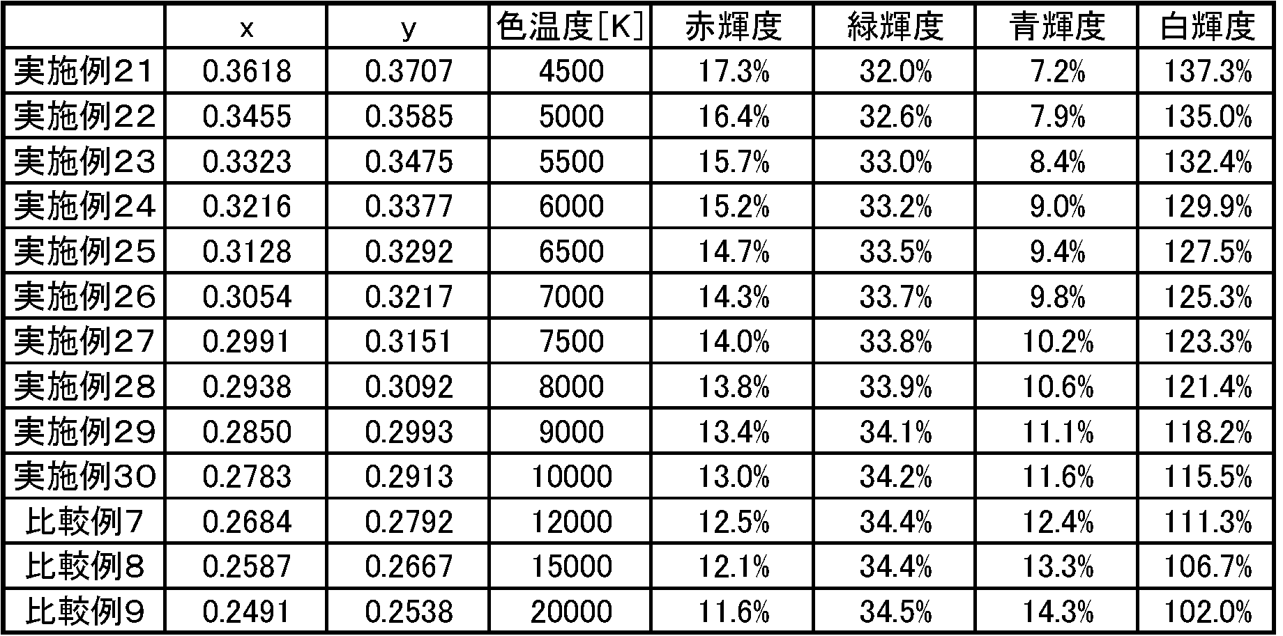
表3に示すように、白色光の色温度を10000K以下に設定することで、白輝度及び赤輝度が向上した。これにより、RGBY方式の液晶表示装置において、赤輝度を改善するとともに、低消費電力化を図ることができる。一方、青輝度は、白色光の色温度を低く設定すると低下するが、青輝度は低下しても画質に大きな影響は与えない。なお、緑輝度は、白色光の色温度を低く設定しても、大きな変化は見られなかった。
画質の観点からは、赤輝度が12%以上、緑輝度が30%以上、青輝度が8%以上であることがより好ましいが、実施形態3の液晶表示装置においては、白色光の色温度が4500K~10000K(実施例21~30)のとき、上記の条件を満たした。また、白色光の色温度が12000K及び15000K(比較例7及び8)のときも上記の条件は満たしたが、白色光の色温度が4500K~10000Kのときに比べると赤輝度及び白輝度が低下していた。
実施形態3の液晶表示装置においては、赤色及び青色の開口の合計面積比率を緑色及び黄色の開口の合計面積比率の1.4倍とすることで、実施形態2の液晶表示装置よりも更に赤輝度を向上させられることが判明した。
(実施形態4)
図6は、実施形態4に係る液晶表示装置を示す断面模式図である。実施形態1の液晶表示装置500は、カラーフィルタ10R、10G、10B及び10Yの面積が同じ大きさに形成されていたが、実施形態2の液晶表示装置530は、図6に示すように、カラーフィルタ10R及び10Bの合計面積がカラーフィルタ10G及び10Yの1.6倍となり、赤色及び青色の開口の合計面積比率は、緑色及び黄色の開口の合計面積比率の1.6倍となる。それ以外は実施形態4の液晶表示装置530は、実施形態1の液晶表示装置500と同様である。
図6は、実施形態4に係る液晶表示装置を示す断面模式図である。実施形態1の液晶表示装置500は、カラーフィルタ10R、10G、10B及び10Yの面積が同じ大きさに形成されていたが、実施形態2の液晶表示装置530は、図6に示すように、カラーフィルタ10R及び10Bの合計面積がカラーフィルタ10G及び10Yの1.6倍となり、赤色及び青色の開口の合計面積比率は、緑色及び黄色の開口の合計面積比率の1.6倍となる。それ以外は実施形態4の液晶表示装置530は、実施形態1の液晶表示装置500と同様である。
実施形態4に係る液晶表示装置において、白色光の色温度を4500K~20000Kに変更し、白輝度と、この白輝度を100%としたときの赤輝度、緑輝度、及び、青輝度(%)を測定した。なお上記白輝度とは、比較形態1(赤色、青色、緑色の3色のカラーフィルタが配されたカラーフィルタ基板を有する液晶表示装置であって、射出される白色光の色温度が12000Kの液晶表示装置)の白輝度(3色系白輝度)を100%としたときの輝度である。結果を表4に示す。白色光の色温度を4500Kとしたものを実施例31、白色光の色温度を5000Kとしたものを実施例32、白色光の色温度を5500Kとしたものを実施例33、白色光の色温度を6000Kとしたものを実施例34、白色光の色温度を6500Kとしたものを実施例35、白色光の色温度を7000Kとしたものを実施例36、白色光の色温度を7500Kとしたものを実施例37、白色光の色温度を8000Kとしたものを実施例38、白色光の色温度を9000Kとしたものを実施例39、及び、白色光の色温度を10000Kとしたものを実施例40とした。また、白色光の色温度を12000Kとしたものを比較例10、白色光の色温度を15000Kとしたものを比較例11、及び、白色光の色温度を20000Kとしたものを比較例12とした。
色温度及び輝度は、液晶表示装置の表示面の鉛直方向に設置された超低輝度分光放射計SR-UL1(トプコン社製)により測定された。
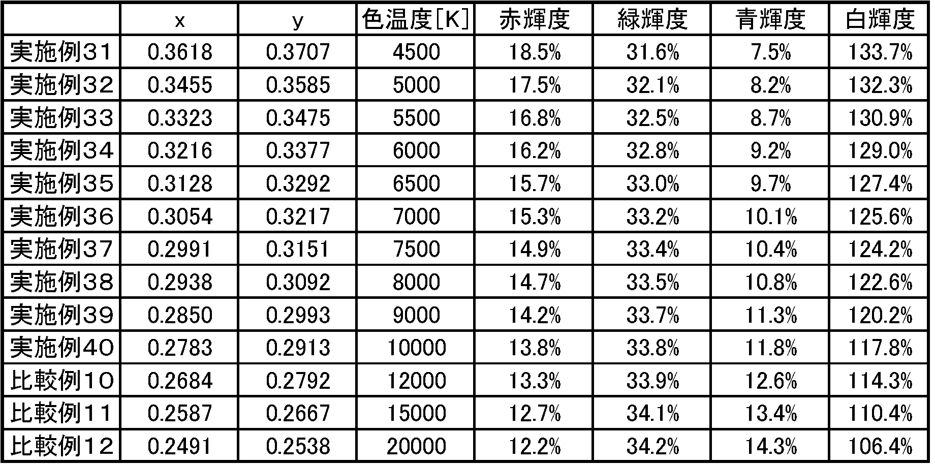
表4に示すように、白色光の色温度を10000K以下に設定することで、白輝度及び赤輝度が向上した。これにより、RGBY方式の液晶表示装置において、赤輝度を改善するとともに、低消費電力化を図ることができる。一方、青輝度は、白色光の色温度を低く設定すると低下するが、青輝度は低下しても画質に大きな影響は与えない。なお、緑輝度は、白色光の色温度を低く設定しても、大きな変化は見られなかった。
画質の観点からは、赤輝度が12%以上、緑輝度が30%以上、青輝度が8%以上であることがより好ましいが、実施形態4の液晶表示装置においては、白色光の色温度が4500K~10000K(実施例31~40)のとき、上記の条件を満たした。また、白色光の色温度が12000K~20000K(比較例10~12)のときも上記の条件は満たしたが、白色光の色温度が4500K~10000Kのときに比べると赤輝度及び白輝度が低下していた。更に、画質の観点からは、赤輝度が15%以上、緑輝度が30%以上、青輝度が10%以上であることが特に好ましいが、実施形態4の液晶表示装置においては、白色光の色温度が7000K(実施例36)のとき、上記の条件を満たした。
実施形態4の液晶表示装置においては、赤色及び青色の開口の合計面積比率を緑色及び黄色の開口の合計面積比率の1.6倍とすることで、実施形態3の液晶表示装置よりも更に赤輝度を向上させられることが判明した。
(実施形態5)
図7は、実施形態5に係る液晶表示装置を示す断面模式図である。実施形態1の液晶表示装置500は、カラーフィルタ10R、10G、10B及び10Yの面積が同じ大きさに形成されていたが、実施形態5の液晶表示装置540は、図7に示すように、カラーフィルタ10R及び10Bの合計面積がカラーフィルタ10G及び10Yの1.8倍となり、赤色及び青色の開口の合計面積比率は、緑色及び黄色の開口の合計面積比率の1.8倍となる。それ以外は実施形態5の液晶表示装置540は、実施形態1の液晶表示装置500と同様である。
図7は、実施形態5に係る液晶表示装置を示す断面模式図である。実施形態1の液晶表示装置500は、カラーフィルタ10R、10G、10B及び10Yの面積が同じ大きさに形成されていたが、実施形態5の液晶表示装置540は、図7に示すように、カラーフィルタ10R及び10Bの合計面積がカラーフィルタ10G及び10Yの1.8倍となり、赤色及び青色の開口の合計面積比率は、緑色及び黄色の開口の合計面積比率の1.8倍となる。それ以外は実施形態5の液晶表示装置540は、実施形態1の液晶表示装置500と同様である。
実施形態5に係る液晶表示装置において、白色光の色温度を4500K~20000Kに変更し、白輝度と、この白輝度を100%としたときの赤輝度、緑輝度、及び、青輝度(%)を測定した。なお上記白輝度とは、比較形態1(赤色、青色、緑色の3色のカラーフィルタが配されたカラーフィルタ基板を有する液晶表示装置であって、射出される白色光の色温度が12000Kの液晶表示装置)の白輝度(3色系白輝度)を100%としたときの輝度である。結果を表5に示す。白色光の色温度を4500Kとしたものを実施例41、白色光の色温度を5000Kとしたものを実施例42、白色光の色温度を5500Kとしたものを実施例43、白色光の色温度を6000Kとしたものを実施例44、白色光の色温度を6500Kとしたものを実施例45、白色光の色温度を7000Kとしたものを実施例46、白色光の色温度を7500Kとしたものを実施例47、白色光の色温度を8000Kとしたものを実施例48、白色光の色温度を9000Kとしたものを実施例49、及び、白色光の色温度を10000Kとしたものを実施例50とした。また、白色光の色温度を12000Kとしたものを比較例13、白色光の色温度を15000Kとしたものを比較例14、及び、白色光の色温度を20000Kとしたものを比較例15とした。
色温度及び輝度は、液晶表示装置の表示面の鉛直方向に設置された超低輝度分光放射計SR-UL1(トプコン社製)により測定された。
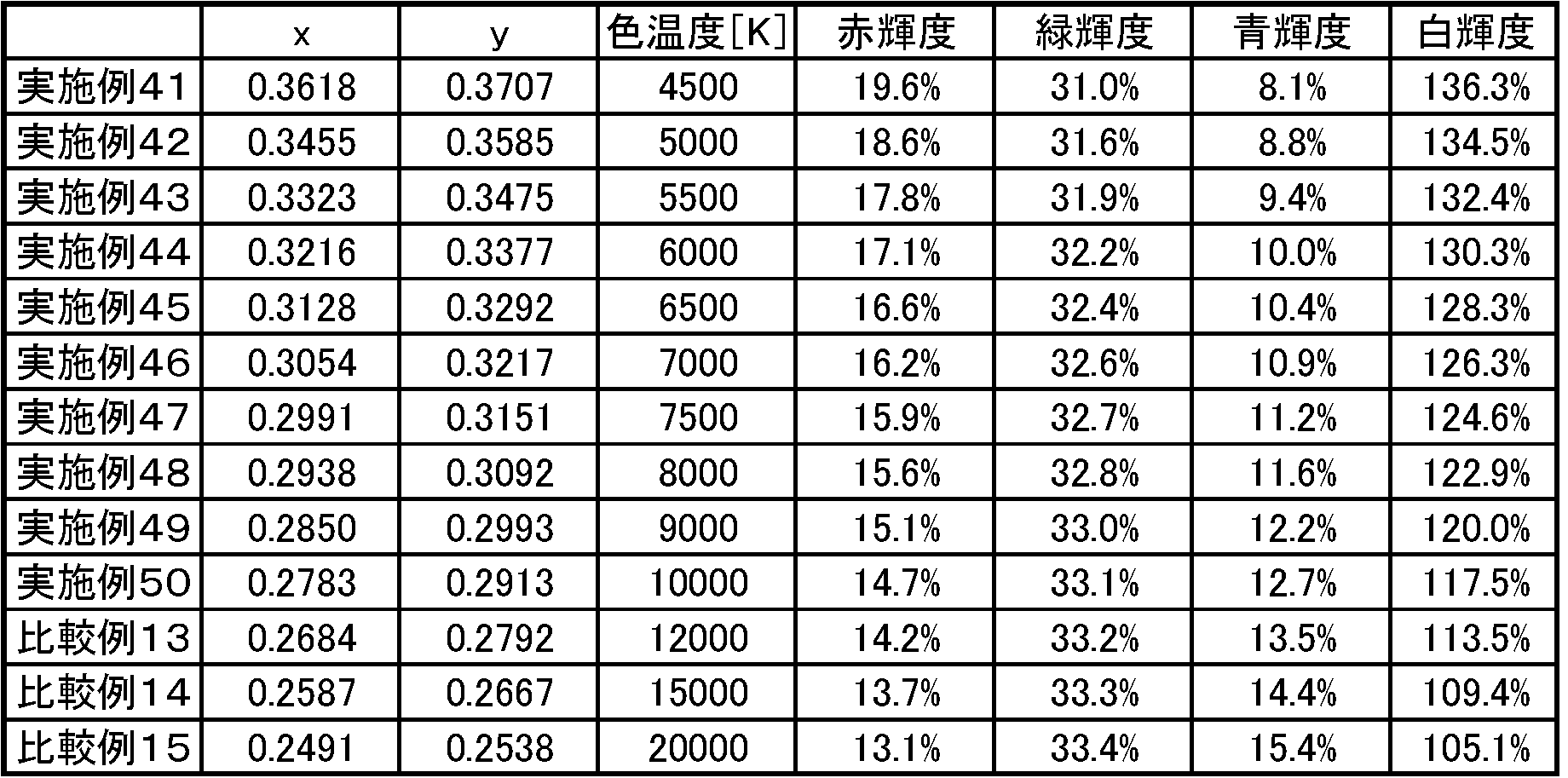
表5に示すように、白色光の色温度を10000K以下に設定することで、白輝度及び赤輝度が向上した。これにより、RGBY方式の液晶表示装置において、赤輝度を改善するとともに、低消費電力化を図ることができる。一方、青輝度は、白色光の色温度を低く設定すると低下するが、青輝度は低下しても画質に大きな影響は与えない。なお、緑輝度は、白色光の色温度を低く設定しても、大きな変化は見られなかった。
画質の観点からは、赤輝度が12%以上、緑輝度が30%以上、青輝度が8%以上であることがより好ましいが、実施形態5の液晶表示装置においては、白色光の色温度が4500K~10000K(実施例41~50)のとき、上記の条件を満たした。また、白色光の色温度が12000K~20000K(比較例13~15)のときも上記の条件は満たしたが、白色光の色温度が4500K~10000Kのときに比べると赤輝度及び白輝度が低下していた。更に、画質の観点からは、赤輝度が15%以上、緑輝度が30%以上、青輝度が10%以上であることが特に好ましいが、実施形態5の液晶表示装置においては、白色光の色温度が6000K~9000K(実施例44~49)のとき、上記の条件を満たした。
また、実施形態5の液晶表示装置においては、赤色及び青色の開口の合計面積比率を緑色及び黄色の開口の合計面積比率の1.8倍とすることで、実施形態4の液晶表示装置よりも更に赤輝度を向上させられることが判明した。
(実施形態6)
図8は、実施形態6に係る液晶表示装置を示す断面模式図である。実施形態1の液晶表示装置500は、カラーフィルタ10R、10G、10B及び10Yの面積が同じ大きさに形成されていたが、実施形態6の液晶表示装置550は、図8に示すように、カラーフィルタ10R及び10Bの合計面積がカラーフィルタ10G及び10Yの2.0倍となり、赤色及び青色の開口の合計面積比率は、緑色及び黄色の開口の合計面積比率の2.0倍となる。それ以外は実施形態6の液晶表示装置550は、実施形態1の液晶表示装置500と同様である。
図8は、実施形態6に係る液晶表示装置を示す断面模式図である。実施形態1の液晶表示装置500は、カラーフィルタ10R、10G、10B及び10Yの面積が同じ大きさに形成されていたが、実施形態6の液晶表示装置550は、図8に示すように、カラーフィルタ10R及び10Bの合計面積がカラーフィルタ10G及び10Yの2.0倍となり、赤色及び青色の開口の合計面積比率は、緑色及び黄色の開口の合計面積比率の2.0倍となる。それ以外は実施形態6の液晶表示装置550は、実施形態1の液晶表示装置500と同様である。
実施形態6に係る液晶表示装置において、白色光の色温度を4500K~20000Kに変更し、白輝度と、この白輝度を100%としたときの赤輝度、緑輝度、及び、青輝度(%)を測定した。なお上記白輝度とは、比較形態1(赤色、青色、緑色の3色のカラーフィルタが配されたカラーフィルタ基板を有する液晶表示装置であって、射出される白色光の色温度が12000Kの液晶表示装置)の白輝度(3色系白輝度)を100%としたときの輝度である。結果を表6に示す。白色光の色温度を4500Kとしたものを実施例51、白色光の色温度を5000Kとしたものを実施例52、白色光の色温度を5500Kとしたものを実施例53、白色光の色温度を6000Kとしたものを実施例54、白色光の色温度を6500Kとしたものを実施例55、白色光の色温度を7000Kとしたものを実施例56、白色光の色温度を7500Kとしたものを実施例57、白色光の色温度を8000Kとしたものを実施例58、白色光の色温度を9000Kとしたものを実施例59、及び、白色光の色温度を10000Kとしたものを実施例60とした。また、白色光の色温度を12000Kとしたものを比較例16、白色光の色温度を15000Kとしたものを比較例17、及び、白色光の色温度を20000Kとしたものを比較例18とした。
色温度及び輝度は、液晶表示装置の表示面の鉛直方向に設置された超低輝度分光放射計SR-UL1(トプコン社製)により測定された。

表6に示すように、白色光の色温度を10000K以下に設定することで、白輝度及び赤輝度が向上した。これにより、RGBY方式の液晶表示装置において、赤輝度を改善するとともに、低消費電力化を図ることができる。一方、青輝度は、白色光の色温度を低く設定すると低下するが、青輝度は低下しても画質に大きな影響は与えない。なお、緑輝度は、白色光の色温度を低く設定しても、大きな変化は見られなかった。
画質の観点からは、赤輝度が12%以上、緑輝度が30%以上、青輝度が8%以上であることがより好ましいが、実施形態6の液晶表示装置においては、白色光の色温度が4500K~10000K(実施例51~60)のとき、上記の条件を満たした。また、白色光の色温度が12000K~20000K(比較例16~18)のときも上記の条件は満たしたが、白色光の色温度が4500K~10000Kのときに比べると赤輝度及び白輝度が低下していた。更に、画質の観点からは、赤輝度が15%以上、緑輝度が30%以上、青輝度が10%以上であることが特に好ましいが、実施形態5の液晶表示装置においては、白色光の色温度が6000K~10000K(実施例54~60)のとき、上記の条件を満たした。
実施形態6の液晶表示装置においては、赤色及び青色の開口の合計面積比率を緑色及び黄色の開口の合計面積比率の2.0倍とすることで、実施形態5の液晶表示装置よりも更に赤輝度を向上させられることが判明した。
(実施形態7)
図9は、実施形態7に係る液晶表示装置を示す断面模式図である。実施形態1の液晶表示装置500は、カラーフィルタ10R、10G、10B及び10Yの面積が同じ大きさに形成されていたが、実施形態7の液晶表示装置600は、図9に示すように、カラーフィルタ10R及び10Bの合計面積がカラーフィルタ10G及び10Yの2.2倍となり、赤色及び青色の開口の合計面積比率は、緑色及び黄色の開口の合計面積比率の2.2倍となる。それ以外は実施形態7の液晶表示装置600は、実施形態1の液晶表示装置500と同様である。
図9は、実施形態7に係る液晶表示装置を示す断面模式図である。実施形態1の液晶表示装置500は、カラーフィルタ10R、10G、10B及び10Yの面積が同じ大きさに形成されていたが、実施形態7の液晶表示装置600は、図9に示すように、カラーフィルタ10R及び10Bの合計面積がカラーフィルタ10G及び10Yの2.2倍となり、赤色及び青色の開口の合計面積比率は、緑色及び黄色の開口の合計面積比率の2.2倍となる。それ以外は実施形態7の液晶表示装置600は、実施形態1の液晶表示装置500と同様である。
実施形態7に係る液晶表示装置において、白色光の色温度を4500K~20000Kに変更し、白輝度と、この白輝度を100%としたときの赤輝度、緑輝度、及び、青輝度(%)を測定した。なお上記白輝度とは、比較形態1(赤色、青色、緑色の3色のカラーフィルタが配されたカラーフィルタ基板を有する液晶表示装置であって、射出される白色光の色温度が12000Kの液晶表示装置)の白輝度を100%としたときの輝度である。結果を表7に示す。白色光の色温度を4500Kとしたものを実施例61、白色光の色温度を5000Kとしたものを実施例62、白色光の色温度を5500Kとしたものを実施例63、白色光の色温度を6000Kとしたものを実施例64、白色光の色温度を6500Kとしたものを実施例65、白色光の色温度を7000Kとしたものを実施例66、白色光の色温度を7500Kとしたものを実施例67、白色光の色温度を8000Kとしたものを実施例68、白色光の色温度を9000Kとしたものを実施例69、及び、白色光の色温度を10000Kとしたものを実施例70とした。また、白色光の色温度を12000Kとしたものを比較例19、白色光の色温度を15000Kとしたものを比較例20、及び、白色光の色温度を20000Kとしたものを比較例21とした。
色温度及び輝度は、液晶表示装置の表示面の鉛直方向に設置された超低輝度分光放射計SR-UL1(トプコン社製)により測定された。

画質の観点からは、赤輝度が12%以上、緑輝度が30%以上、青輝度が8%以上であることがより好ましいが、実施形態7の液晶表示装置においては、白色光の色温度が4500K~20000K(実施例61~70、及び、比較例19~21)のとき、上記の条件を満たした。しかし、実施形態7においては、表示ムラ及び表示のざらつきが観察された。これは、赤色及び青色の開口面積が、緑色及び黄色の開口面積に比べ、2.2倍と大きく、画素容量の不均一性が増したために、表示ムラを起こし、また、赤色及び青色の開口面積を大きくすることで、画素全体が大きくなってしまうため、表示がざらついたものと考えられる。
次に、図10~13を用いて、実施形態1~6の液晶表示装置における白色光の色温度と各色の輝度との関係について説明する。図10は、実施形態1~6の液晶表示装置における白色光の色温度と白輝度との関係を示すグラフであり、図11は、実施形態1~6の液晶表示装置における白色光の色温度と赤輝度との関係を示すグラフである。また、図12は、実施形態1~6の液晶表示装置における白色光の色温度と緑輝度との関係を示すグラフであり、図13は、実施形態1~6の液晶表示装置における白色光の色温度と青輝度との関係を示すグラフである。図10に示すように、白色光の色温度が10000K以下になると、白輝度は急激に改善される。また、図11に示すように白色光の色温度が10000K以下になると、赤輝度も急激に改善される。同時に、赤輝度は、赤色及び青色の開口の合計面積比率が大きくなる程、良好な値を示した。このように、RGBY方式の液晶表示装置において、白色光の色温度を10000K以下とするとともに、表示ムラや表示のざらつきが生じない範囲で赤色及び青色の開口の合計面積比率を大きくすることで、赤輝度を改善するとともに、低消費電力化を図ることができる。一方、緑輝度は、図12に示すように、白色光の色温度を変化させても、大きく変化せず、青輝度は、図13に示すように、白色光の色温度を低く設定すると低下するが、青輝度は低下しても画質に大きな影響は与えない。
実施形態7の実施例61~70で示された通り、赤輝度を向上させる観点からは、赤色及び青色の開口の合計面積比率が大きくする程、良好な結果が得られるが、その反面、赤色及び青色の開口の合計面積比率を大きくしすぎると、表示ムラや表示のざらつきが発生するおそれがある。以上から、赤色及び青色の開口の合計面積比率は、緑色及び黄色の開口の合計面積比率に対して、1.2倍以上、2倍以下であることが好ましく、1.8倍以下であることがより好ましい。
次に、図14及び図15を用いて、実施形態1~6の液晶表示装置における、開口比率及び色温度と赤輝度及び白輝度との関係について説明する。
図14は、実施形態1~6の液晶表示装置において、縦軸を開口比率、横軸を白色光の色温度としたときの赤輝度(%)を示すグラフである。グラフ中の開口比率が1.2とは、赤色及び青色の開口の合計面積比率(RB)が、緑色及び黄色の開口の合計面積比率(GY)の1.2倍であることを意味する。図14に示すように、開口比率を大きくする、すなわち、RBを大きくすることで、赤輝度を向上させることができる。また、白色光の色温度を下げることによっても、赤輝度を向上させることができる。
図15は、実施形態1~6の液晶表示装置において、縦軸を開口比率、横軸を白色光の色温度としたときの白輝度(%)を示すグラフである。図15に示すように、白色光の色温度を下げることで、白輝度を大幅に向上させることができる。また、開口比率を大きくする、すなわち、RBを大きくすることによっても白輝度を向上させることができる。
図14及び図15から、実施形態1~6の液晶表示装置においては、白色光の色温度を下げるとともに、開口比率を大きくすることで、白輝度及び赤輝度を向上させることが可能となり、赤輝度を改善するとともに低消費電力化を図ることができる。
(実施形態8)
実施形態1~7においては、白色光の色度が色温度(または相関色温度)で示されたが、実施形態8においては、白色光の色度が色温度で示されない。すなわち、白色光の色度が黒体輻射上又は黒体輻射近傍上に設定されない。それ以外は実施形態8の液晶表示装置は、実施形態4の液晶表示装置と同様であり、実施形態8の液晶表示装置は、カラーフィルタ10R及び10Bの合計面積がカラーフィルタ10G及び10Yの1.6倍となり、赤色及び青色の開口の合計面積比率は、緑色及び黄色の開口の合計面積比率の1.6倍となる。
実施形態1~7においては、白色光の色度が色温度(または相関色温度)で示されたが、実施形態8においては、白色光の色度が色温度で示されない。すなわち、白色光の色度が黒体輻射上又は黒体輻射近傍上に設定されない。それ以外は実施形態8の液晶表示装置は、実施形態4の液晶表示装置と同様であり、実施形態8の液晶表示装置は、カラーフィルタ10R及び10Bの合計面積がカラーフィルタ10G及び10Yの1.6倍となり、赤色及び青色の開口の合計面積比率は、緑色及び黄色の開口の合計面積比率の1.6倍となる。
図16は、実施形態8において、色度(x,y)で示される白色光の白輝度を100%としたときの赤輝度(%)を示すグラフである。良好な表示品位を保つためには、赤輝度は12%以上必要であり、図16の太線に囲まれた領域に白色光の色度(x,y)が存在するとき、赤輝度は、12%以上となる。
図17は、実施形態8において、比較形態1(赤色、青色、緑色の3色のカラーフィルタが配されたカラーフィルタ基板を有する液晶表示装置であって、射出される白色光の色温度が12000K)の白輝度を100%としたときの色度(x,y)で示される白色光の白輝度(%)を示すグラフである。良好な表示品位を保つためには、白輝度は100%以上必要であり、図17の破線に囲まれた領域に白色光の色度(x,y)が存在するとき、白輝度は、100%以上となる。
図18は、実施形態8において、色度(x,y)で示される白色光の白輝度を100%としたときの青輝度(%)を示すグラフである。良好な表示品位を保つためには、青輝度は8%以上必要であり、図18の一点鎖線に囲まれた領域に白色光の色度(x,y)が存在するとき、青輝度は、8%以上となる。
図19は、実施形態8において、色度(x,y)で示される白色光の白輝度を100%としたときの緑輝度(%)を示すグラフである。良好な表示品位を保つためには、緑輝度は30%以上必要であり、図19の二点鎖線に囲まれた領域に白色光の色度(x,y)が存在するとき、緑輝度は、30%以上となる。
図20は、図16~19を重ね合わせたグラフである。図20の太線、破線、一点鎖線、及び、二点鎖線に囲まれた領域、すなわち、図20の波線模様で示される領域に白色光の色度(x,y)が存在するとき、実施形態8の液晶表示装置において、赤輝度が12%以上、白輝度が比較形態1の白輝度に比べ100%以上、青輝度が8%以上、及び、緑輝度が30%以上となり、赤輝度を改善するとともに、低消費電力化を図ることができる。
なお、本願は、2010年12月8日に出願された日本国特許出願2010-273925号を基礎として、パリ条約ないし移行する国における法規に基づく優先権を主張するものである。該出願の内容は、その全体が本願中に参照として組み込まれている。
3:補助容量
4:走査線
6:信号線
7:補助容量配線
8:TFT
9:ドレイン引出し配線
10R:赤フィルタ
10G:緑フィルタ
10B:青フィルタ
10Y:黄フィルタ
10BM:ブラックマトリクス
21、31:ガラス基板
22、32:位相差板
23、33:偏光板
25:オーバーコート層
26:対向電極
27、38:配向膜
34:層間絶縁膜
35:透明電極
36:バックライト
100:対向基板
200:TFT基板
300:液晶層
500、510、520、530、540、550、600:液晶表示装置
4:走査線
6:信号線
7:補助容量配線
8:TFT
9:ドレイン引出し配線
10R:赤フィルタ
10G:緑フィルタ
10B:青フィルタ
10Y:黄フィルタ
10BM:ブラックマトリクス
21、31:ガラス基板
22、32:位相差板
23、33:偏光板
25:オーバーコート層
26:対向電極
27、38:配向膜
34:層間絶縁膜
35:透明電極
36:バックライト
100:対向基板
200:TFT基板
300:液晶層
500、510、520、530、540、550、600:液晶表示装置
Claims (12)
- 少なくとも4色のカラーフィルタが画素毎に配置されたカラーフィルタ基板を備える液晶表示装置であって、
該液晶表示装置は、表示面から射出される白色光の色温度が12000K未満であることを特徴とする液晶表示装置。 - 前記液晶表示装置は、表示面から射出される白色光の色温度が10000K以下であることを特徴とする請求項1に記載の液晶表示装置。
- 前記カラーフィルタ基板は、少なくとも、赤色、緑色、青色、及び、黄色のカラーフィルタからなり、前記液晶表示装置は、赤色、緑色、青色、及び、黄色の開口を有することを特徴とする請求項1又は2記載の液晶表示装置。
- 前記液晶表示装置は、赤色及び青色の開口の合計面積比率をRBとし、緑色及び黄色の開口の合計面積比率をGYとすると、
RB>GY
であることを特徴とする請求項3記載の液晶表示装置。 - 前記液晶表示装置は、
RB:GY=1.6:1.0
であることを特徴とする請求項4に記載の液晶表示装置。 - 前記液晶表示装置は、
RB:GY=2.0:1.0
であることを特徴とする請求項4に記載の液晶表示装置。 - 前記白色光の輝度は、赤色、緑色、及び、青色の3色カラーフィルタが配置されたカラーフィルタ基板を備える3色系液晶表示装置の表示面から射出される色温度が12000Kの3色系白色光の輝度を100%とすると、100%以上であることを特徴とする請求項1~6のいずれかに記載の液晶表示装置。
- 前記液晶表示装置の表示面から射出される赤色光の輝度は、前記白色光の輝度を100%としたとき、12%以上であることを特徴とする請求項1~7のいずれかに記載の液晶表示装置。
- 前記液晶表示装置の表示面から射出される緑色光の輝度は、前記白色光の輝度を100%としたとき、30%以上であることを特徴とする請求項1~8のいずれかに記載の液晶表示装置。
- 前記液晶表示装置の表示面から射出される青色光の輝度は、前記白色光の輝度を100%としたとき、8%以上であることを特徴とする請求項1~9のいずれかに記載の液晶表示装置。
- 少なくとも、赤色、緑色、及び、青色の3色に加え、該3色よりも明度の高い他の色のカラーフィルタが画素毎に配置されたカラーフィルタ基板を備える液晶表示装置であって、
該液晶表示装置の表示面から射出される白色光の色度(x,y)が、以下の(1)~(4)を満たす範囲にあることを特徴とする液晶表示装置。
(1)前記白色光の輝度は、赤色、緑色、及び、青色の3色カラーフィルタが配置されたカラーフィルタ基板を備える3色系液晶表示装置であって、色温度が12000Kのときの3色系白色光の輝度を100%とすると、100%以上である。
(2)前記液晶表示装置の表示面から射出される赤色光の輝度は、前記白色光の輝度を100%とすると、12%以上である。
(3)前記液晶表示装置の表示面から射出される緑色光の輝度は、前記白色光の輝度を100%とすると、30%以上である。
(4)前記液晶表示装置の表示面から射出される青色光の輝度は、前記白色光の輝度を100%とすると、8%以上である。 - 前記他の色は、黄色であることを特徴とする請求項11記載の液晶表示装置。
Priority Applications (1)
| Application Number | Priority Date | Filing Date | Title |
|---|---|---|---|
| US13/992,293 US20130258258A1 (en) | 2010-12-08 | 2011-12-01 | Liquid crystal display device |
Applications Claiming Priority (2)
| Application Number | Priority Date | Filing Date | Title |
|---|---|---|---|
| JP2010273925 | 2010-12-08 | ||
| JP2010-273925 | 2010-12-08 |
Publications (1)
| Publication Number | Publication Date |
|---|---|
| WO2012077565A1 true WO2012077565A1 (ja) | 2012-06-14 |
Family
ID=46207055
Family Applications (1)
| Application Number | Title | Priority Date | Filing Date |
|---|---|---|---|
| PCT/JP2011/077776 Ceased WO2012077565A1 (ja) | 2010-12-08 | 2011-12-01 | 液晶表示装置 |
Country Status (2)
| Country | Link |
|---|---|
| US (1) | US20130258258A1 (ja) |
| WO (1) | WO2012077565A1 (ja) |
Cited By (2)
| Publication number | Priority date | Publication date | Assignee | Title |
|---|---|---|---|---|
| US10580370B2 (en) | 2017-10-23 | 2020-03-03 | Japan Display Inc. | Display device |
| US10636370B2 (en) | 2017-12-12 | 2020-04-28 | Japan Display Inc. | Display device |
Families Citing this family (3)
| Publication number | Priority date | Publication date | Assignee | Title |
|---|---|---|---|---|
| JP6051605B2 (ja) * | 2012-06-13 | 2016-12-27 | ソニー株式会社 | 表示装置、および表示制御方法、並びにプログラム |
| JP6314451B2 (ja) * | 2012-12-27 | 2018-04-25 | 大日本印刷株式会社 | カラーフィルタ形成基板および有機el表示装置 |
| CN103197477B (zh) | 2013-03-29 | 2015-11-18 | 京东方科技集团股份有限公司 | 一种双模液晶显示装置、彩膜基板及阵列基板 |
Citations (3)
| Publication number | Priority date | Publication date | Assignee | Title |
|---|---|---|---|---|
| WO2006109567A1 (ja) * | 2005-04-05 | 2006-10-19 | Sharp Kabushiki Kaisha | 反射透過両用型の表示装置 |
| WO2007108195A1 (ja) * | 2006-03-20 | 2007-09-27 | Sharp Kabushiki Kaisha | 表示装置 |
| WO2007148519A1 (ja) * | 2006-06-19 | 2007-12-27 | Sharp Kabushiki Kaisha | 表示装置 |
Family Cites Families (1)
| Publication number | Priority date | Publication date | Assignee | Title |
|---|---|---|---|---|
| US7880834B2 (en) * | 2006-03-17 | 2011-02-01 | Sharp Kabushiki Kaisha | Liquid crystal display device |
-
2011
- 2011-12-01 WO PCT/JP2011/077776 patent/WO2012077565A1/ja not_active Ceased
- 2011-12-01 US US13/992,293 patent/US20130258258A1/en not_active Abandoned
Patent Citations (3)
| Publication number | Priority date | Publication date | Assignee | Title |
|---|---|---|---|---|
| WO2006109567A1 (ja) * | 2005-04-05 | 2006-10-19 | Sharp Kabushiki Kaisha | 反射透過両用型の表示装置 |
| WO2007108195A1 (ja) * | 2006-03-20 | 2007-09-27 | Sharp Kabushiki Kaisha | 表示装置 |
| WO2007148519A1 (ja) * | 2006-06-19 | 2007-12-27 | Sharp Kabushiki Kaisha | 表示装置 |
Cited By (2)
| Publication number | Priority date | Publication date | Assignee | Title |
|---|---|---|---|---|
| US10580370B2 (en) | 2017-10-23 | 2020-03-03 | Japan Display Inc. | Display device |
| US10636370B2 (en) | 2017-12-12 | 2020-04-28 | Japan Display Inc. | Display device |
Also Published As
| Publication number | Publication date |
|---|---|
| US20130258258A1 (en) | 2013-10-03 |
Similar Documents
| Publication | Publication Date | Title |
|---|---|---|
| JP5172656B2 (ja) | 表示装置 | |
| US10162088B2 (en) | Image display apparatus | |
| US8339356B2 (en) | Liquid crystal display apparatus capable of maintaining high color purity | |
| CN102597859B (zh) | 液晶显示装置 | |
| US20090073358A1 (en) | Liquid crystal display device | |
| US7850337B2 (en) | LCD device and method of driving the LCD device | |
| JPWO2007108195A1 (ja) | 表示装置 | |
| KR101664225B1 (ko) | 액정표시장치 | |
| JP4425681B2 (ja) | 液晶表示装置 | |
| WO2012077565A1 (ja) | 液晶表示装置 | |
| US8421966B2 (en) | Liquid crystal display comprising red, green, blue, and yellow sub-pixels having chromaticity on a CIE1931 chromaticity diagram wherein the sub-pixels have different areas | |
| WO2012169421A1 (ja) | 表示装置 | |
| US20180180949A1 (en) | Liquid crystal display panel and liquid crystal display device | |
| US20060209004A1 (en) | LCD device having a homogeneous LC layer | |
| KR101344641B1 (ko) | 액정 표시 장치 | |
| KR101768232B1 (ko) | 액정표시장치 | |
| US20060132679A1 (en) | Liquid crystal display with high color gamut | |
| WO2011102184A1 (ja) | 表示装置及びテレビ受信装置 | |
| JP2015210331A (ja) | 液晶表示装置 |
Legal Events
| Date | Code | Title | Description |
|---|---|---|---|
| 121 | Ep: the epo has been informed by wipo that ep was designated in this application |
Ref document number: 11847533 Country of ref document: EP Kind code of ref document: A1 |
|
| WWE | Wipo information: entry into national phase |
Ref document number: 13992293 Country of ref document: US |
|
| NENP | Non-entry into the national phase |
Ref country code: DE |
|
| 122 | Ep: pct application non-entry in european phase |
Ref document number: 11847533 Country of ref document: EP Kind code of ref document: A1 |
|
| NENP | Non-entry into the national phase |
Ref country code: JP |