WO2012077544A1 - 画像処理方法及び撮像装置 - Google Patents
画像処理方法及び撮像装置 Download PDFInfo
- Publication number
- WO2012077544A1 WO2012077544A1 PCT/JP2011/077617 JP2011077617W WO2012077544A1 WO 2012077544 A1 WO2012077544 A1 WO 2012077544A1 JP 2011077617 W JP2011077617 W JP 2011077617W WO 2012077544 A1 WO2012077544 A1 WO 2012077544A1
- Authority
- WO
- WIPO (PCT)
- Prior art keywords
- distortion correction
- image
- parameter
- virtual projection
- coordinate system
- Prior art date
- Legal status (The legal status is an assumption and is not a legal conclusion. Google has not performed a legal analysis and makes no representation as to the accuracy of the status listed.)
- Ceased
Links
Images






Classifications
-
- G—PHYSICS
- G06—COMPUTING OR CALCULATING; COUNTING
- G06T—IMAGE DATA PROCESSING OR GENERATION, IN GENERAL
- G06T3/00—Geometric image transformations in the plane of the image
-
- H—ELECTRICITY
- H04—ELECTRIC COMMUNICATION TECHNIQUE
- H04N—PICTORIAL COMMUNICATION, e.g. TELEVISION
- H04N23/00—Cameras or camera modules comprising electronic image sensors; Control thereof
- H04N23/80—Camera processing pipelines; Components thereof
Definitions
- the present invention relates to an image processing method and an imaging apparatus that perform distortion correction processing of a moving image captured by an imaging device via an optical system including a condenser lens.
- Patent Document 1 discloses a correction method of the prior art that corrects distortion generated in a captured image captured using a lens with a short focal length using a lens correction parameter.
- Patent Document 2 for the purpose of reducing the capacity of an image memory, image data subjected to image processing in an image memory corresponding to the resolution of output image data without depending on the amount of image data corresponding to the resolution on the image sensor side.
- a processing device is disclosed.
- this image data processing apparatus when camera shake correction processing and distortion correction processing are performed together with this, the processing is divided into two processes of horizontal camera shake correction and vertical camera shake correction, and writing is performed in the first memory and the second memory, respectively.
- the first memory images after horizontal camera shake correction processing after resolution conversion in accordance with the resolution of the output image are sequentially stored for each line, and images of a plurality of horizontal lines that enable vertical camera shake correction are accumulated.
- reading from the first memory is performed to perform vertical image stabilization, and the processed image is stored in the second memory.
- Patent Document 1 there is a problem that when a captured image obtained by a lens is hardwareized as an image processing device, the processing time becomes long, the circuit scale increases, and the cost increases. .
- the image after the distortion correction processing has a narrow viewing angle, it is difficult to recognize a wide area at a time.
- An image that is not subjected to distortion correction processing has a wide viewing angle, but on the other hand, the subject is distorted, making it difficult to recognize the sense of distance and size.
- Patent Document 2 correction processing in the horizontal direction and vertical direction is performed twice, and image data of a plurality of horizontal lines is processed in order to perform vertical camera shake correction.
- image data obtained from a camera using an optical system using a lens with a short focal length the amount of vertical displacement due to distortion also changes according to the position of the image sensor (mainly the distance from the optical center).
- the present invention can reduce processing time and accurately recognize a subject even in a relatively small circuit of a low-capacity image memory.
- An object is to provide an image processing method and an imaging apparatus.
- the distortion correction parameter set in the first step is at least one of a parameter for moving the position of the virtual projection plane for each frame and a parameter for changing the lens parameter for each frame.
- An imaging device having a plurality of pixels and reading out in a predetermined order;
- a setting unit for setting the position and size of the virtual projection plane in the world coordinate system;
- a distortion correction parameter generating unit that sets a distortion correction parameter and a distortion correction parameter determined by the position or size of the virtual projection plane in the world coordinate system;
- the coordinates in the world coordinate system of each pixel of the virtual projection plane set by the setting unit are converted into a camera coordinate system based on the distortion correction parameter, and the coordinates in the converted camera coordinate system and a plurality of data read out from the imaging device
- a distortion correction processing unit that calculates image data on the virtual projection plane based on the pixel data of An image output unit that outputs the calculated image data as a moving image;
- Have The distortion correction processing unit calculates a reading area of the image sensor based on the set distortion correction parameter, calculates a time required for the reading process of the image sensor from the calculated reading area, and calculates the required time calculated for each frame.
- An image pickup apparatus wherein pixel
- the distortion correction parameter is at least one of a parameter for moving the position of the virtual projection plane for each frame and a parameter for changing the lens parameter for each frame.
- each pixel on the virtual projection plane is converted into a camera coordinate system, and based on the coordinates in the converted camera coordinate system and a plurality of pixel data of the image sensor, image data on the virtual projection plane is calculated.
- the readout area of the image sensor is calculated, the required time for the readout process of the image sensor is calculated from the calculated readout area, and the pixel data is read from the image sensor at the readout start timing set from the required time calculated for each frame.
- the position of the virtual projection plane VP is changed with the image center o in the camera coordinate system as the rotation center.
- the position of the virtual projection plane VP is changed with the image center o in the camera coordinate system as the movement center.
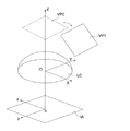
- FIG. 1 is a schematic diagram for explaining distortion correction according to the present embodiment.
- X, Y, and Z are world coordinate systems, and the origin O is the lens center.
- Z includes the optical axis, and the XY plane includes the lens center plane LC passing through the lens center O.
- Point P is an object point of the subject in the world coordinate system XYZ.
- ⁇ is an incident angle with respect to the optical axis (coincident with the Z axis) at the lens center (origin O).
- X and y are camera coordinate systems, and the xy plane corresponds to the image sensor surface IA.
- o is the optical center, which is the intersection of the optical axis Z of the optical system and the image sensor surface.
- the point p is a point on the image sensor surface in the camera coordinate system, and the object point P is referred to as a parameter based on the physical characteristics of the lens (hereinafter referred to as “lens parameter”. )
- lens parameter Is used to convert the position of each pixel of the virtual projection plane VP generated from the optical axis Z to the camera coordinate system using a distortion correction coefficient that associates the image height with the position.
- the VP is a virtual projection plane.
- the virtual projection plane VP is set on the opposite side of the imaging element (and imaging element surface IA) with respect to the lens position (lens center plane LC) of the optical system.
- the virtual projection plane VP can be changed in position and size based on an instruction from the user to the user operation unit 130 (see FIG. 3). Details of the position change will be described later.
- the virtual projection plane VP is arranged at a predetermined position (Z direction) parallel to the lens center plane LC (XY direction) with a predetermined size, and the center of the virtual projection plane VP.
- ov is located on the Z axis.
- Gv is a point where the object point P is projected onto the virtual projection plane VP, and is an intersection of the object point P and a straight line passing through the lens center O and the virtual projection plane VP.
- position change is a concept that includes not only the case where the virtual projection plane VP is translated on the XY plane as shown below, but also an angle change (also referred to as a posture change) with respect to the XY plane.
- the viewpoint is changed along with the position change.
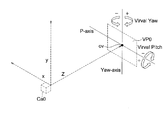
- FIG. 2 shows an example in which the position of the virtual projection plane VP0 is changed with the image center o in the camera coordinate system as the rotation center (or movement center).
- rotation about the x-axis with the image center o as the rotation center is actual pitch (also referred to as tilt)
- rotation about the y-axis is actual yaw (also referred to as pan)
- rotation about the Z-axis Is a real roll.
- FIG. 3 shows an example in which the position of the virtual projection plane VP is changed with the center ov of the virtual projection plane VP0 as the rotation center based on the input rotation amount setting value.
- One of the two axes that are orthogonal to each other on the virtual projection plane VP0 is set as Yaw-axis, and the other as P-axis. Both are axes passing through the center ov, and rotation around the Yaw-axis with the center ov as the rotation center is called virtual yaw rotation, and rotation around the P-axis is called virtual pitch rotation.
- viewpoint conversion corresponding to rotating or changing the position of the virtual camera Ca0 is performed.
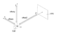
- FIG. 4 shows an example in which the position of the virtual projection plane VP is changed with the image center o in the camera coordinate system as the movement center.
- viewpoint conversion corresponding to the parallel movement of the virtual camera Ca0 together with the virtual projection plane VP is performed.
- FIG. 5 shows an example of the virtual projection plane in a state (VP1) in which the virtual projection plane VP is moved from the initial position (VP0) by real yaw movement.
- FIG. 6 is a block diagram illustrating a schematic configuration of the imaging apparatus.
- the imaging apparatus includes an imaging unit 110, a control unit 100, a display unit 120, and a user operation unit 130.
- the imaging unit 110 includes a short-focus lens, an imaging element, and the like.
- examples of the lens include a wide-angle lens and a fisheye lens.
- the image pickup device for example, there is an XY address type C-MOS image pickup device in which a plurality of pixels (light receiving elements) are arranged in a lattice shape and a switching element is arranged in each of them. A scanning line (x direction) and a signal line (y direction) are connected to the switching element arranged in each pixel, and pixel data from the signal line in a predetermined order is a group of pixels connected to the scanning line. Is read out and image data is output.
- the control unit 100 can set the position and size of the virtual projection plane VP, the distortion correction strength, the change speed of the distortion correction, and the upper and lower limits of the change based on an input instruction to the user operation unit 130.
- the synchronization signal generation circuit 150 generates a horizontal synchronization signal (Hsync), a vertical synchronization signal (Vsync), and a reference clock (clk), and these signals are used as a distortion correction processing unit 101 and a distortion correction parameter generation unit of the control unit 100. 102, and sent to each part of the video memory 104.
- Hsync horizontal synchronization signal
- Vsync vertical synchronization signal
- clk reference clock
- the viewpoint of the camera is changed such as punching, tilting, zooming in, and zooming out, and these settings function as a “setting unit” in the present application. It is converted by the distortion correction parameter generation unit 102 and sent to the distortion correction processing unit 101 as a distortion correction parameter.
- the ROM 108 stores lens parameters based on physical characteristics of the actual lens of the imaging unit 110 and lens parameters when distortion correction is not performed (corresponding to a pinhole lens).
- a distortion correction coefficient is generated based on the lens parameter information stored in the ROM 108.
- the distortion correction coefficient change speed, the change width setting information, the virtual projection plane VP position change speed, and the change width setting information are LUTs. It is sent to the generation unit 103.
- the distortion correction processing unit 101 includes a distortion processing unit 101a and an imaging synchronization signal timing calculation unit 101b.
- the imaging synchronization signal timing calculation unit 101b calculates a time required for reading the imaging element by a process described later. The required time is calculated for each frame and can take a different value for each frame. Based on the calculated required time, the distortion correction processing unit 101 moves up the vertical synchronization signal Vsync input from the synchronization signal generation circuit 150 (transmitted at a predetermined interval) by a time corresponding to the required time. Is output to the imaging unit 110.
- the distortion correction processing unit 101 generates an output image after distortion correction processing from the input image from the imaging unit 110 using the LUT acquired from the LUT generation unit 103.
- the LUT used here is generated by the LUT generation unit 103, and is calculated by using the distortion correction parameter sent from the distortion correction parameter generation unit 102. It describes the correspondence between the pixels and the pixels of the imaging element.
- the output image is written in the video memory 104 and sent to the display unit 120 frame by frame in accordance with the synchronization signal from the synchronization signal generation circuit 150.
- the display unit 120 includes a display screen such as a liquid crystal display, and sequentially displays the output image sent on the display screen.
- the user operation unit 130 includes a keyboard, a mouse, or a touch panel arranged on a liquid crystal display for display, and accepts a user input operation.
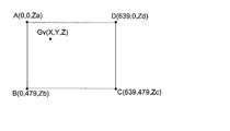
- FIG. 7 is a schematic diagram for explaining a coordinate system. As shown in FIG. 7, four corner points A (0, 0, Za), point B (0, 479, Zb), point C (639, 479, Zc), point D in the virtual projection plane VP in the world coordinate system. A plane surrounded by (639, 0, Zd) is 640 ⁇ 480 at equal intervals. The pixel Gv (total number of pixels 307,000) is divided into pixels, and the coordinates of all the pixels Gv in the world coordinate system are acquired. Note that the values of the X and Y coordinates in the figure are examples, and the X and Y coordinates of the point A are displayed as zero for easy understanding.
- the coordinates Gi (x ′, y ′) is calculated. Specifically, it is calculated by the incident angle ⁇ with respect to the optical axis Z obtained from the distortion correction coefficient and the coordinates of each pixel Gv (reference document: International Publication No. 2010/032720).
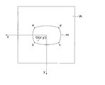
- FIG. 8 is a diagram illustrating a correspondence relationship between the camera coordinate system xy and the imaging element surface IA.
- points a to d are obtained by converting the points A to D in FIG. 7 into the camera coordinate system based on the distortion correction coefficient corresponding to the lens parameter.
- the virtual projection plane VP surrounded by the points A to D is a rectangular plane, but in FIG. 8, the readout area ra surrounded by the points a to d after the coordinate conversion to the camera coordinate system is (virtual projection plane The shape is distorted (corresponding to the position of the VP).
- the figure shows an example in which the barrel shape is distorted, but due to the characteristics of the optical system, it becomes a pincushion type and a Jinkasa type (a barrel shape at the center and a shape that changes to a straight line or a pincushion at the end). In some cases.
- FIG. 9 is a schematic diagram showing the relationship between the image height h and the incident angle ⁇ .
- the image height (distance from the optical axis Z) of the subject (object point P) on the image sensor surface IA is determined by the incident angle ⁇ and the distortion correction coefficient.
- pi is the imaging position of the object point P on the image sensor surface IA determined by the lens parameter for which distortion correction is not performed, and the distance (image height) from the optical axis is the incident angle ⁇ as in a pinhole camera.
- Gi is the image position after distortion correction calculated using the distortion correction coefficient determined by the lens parameter based on the physical characteristics of the actual lens, and the image height at that time is h.
- the coordinates of the camera coordinate system on the imaging element surface IA are determined by the distortion correction coefficient based on the lens parameters and the position of the virtual projection plane VP in the world coordinate system.
- FIG. 10 is a diagram showing a control flow of the present embodiment.
- FIG. 10A is a diagram for explaining the overall control flow
- FIG. 10B is a diagram for explaining the subroutine of step S10 in FIG. 10A.
- step S10 in FIG. 10A distortion correction parameters are set.
- the distortion correction parameter includes (1) distortion correction coefficient and (2) position setting of a virtual projection plane such as viewing angle, real yaw, virtual yaw, real pitch, virtual pitch, and the like.
- the flow of step S10 for setting the distortion correction parameter includes the position setting of the virtual projection plane VP shown in step S101 and the lens parameter setting shown in step S102 as shown in FIG. 10B.
- the setting is performed by the distortion correction parameter generation unit in response to an input from the user operation unit 130.
- the parameters set by these settings include the following four modes. (P1) One virtual projection plane position setting, one lens parameter (P2) Two virtual projection plane position settings, one lens parameter (P3) One virtual projection plane position setting Then, there are two lens parameters (P4), two virtual projection plane position settings, and two lens parameters.
- the lens parameter one of the two lens parameters stored in the ROM 108 is selected.
- the change speed and change width of the distortion correction coefficient are set based on the lens parameters.
- the position change speed and the change width are set.
- the first position V1 of the virtual projection plane VP and the lens parameter L1 are set as the start point
- the second position V1 of the virtual projection plane VP and the lens parameter L2 are set as the end point
- V3 and the lens parameter L3 are calculated by the following formulas (1) and (2), and the change rate parameters VCRatio and DistRatio are set to repeat between 0 and 100% in a cycle of several seconds.
- V3 VCRatio / 100 ⁇ V1 + (1 ⁇ VCRatio / 100) ⁇ V2 Formula (1) (However, 0 ⁇ VCRatio / 100 ⁇ 1)
- L3 DistRatio / 100 ⁇ L1 + (1 ⁇ DistRatio / 100) ⁇ L2 Formula (2) (However, 0 ⁇ DistRatio / 100 ⁇ 1)
- An example of the first position V1 is the initial position shown in FIG. 1 and the like
- an example of the second position V2 is a combination of an actual pitch of ⁇ 45 degrees (see FIG. 2) and a virtual pitch of ⁇ 45 degrees (see FIG. 3). The position (the depression direction from the center of the lens) can be mentioned.
- the lens parameter L1 includes a lens parameter based on physical characteristics of the actual lens, and the lens parameter L2 includes a lens parameter that does not perform distortion correction (corresponding to a pinhole lens).
- the lens parameter L1 is a tan function, which continuously changes to a len parameter L2 of a linear function.
- the size may be set with the change in the position of the virtual projection plane VP.
- step S11 the reading area of the image sensor is calculated.
- the reading area is determined by the distortion correction parameter defined by the position, size, and lens parameter of the virtual projection plane VP set in step S10.
- the world coordinate system described with reference to FIGS. Is performed by performing coordinate transformation (hereinafter also referred to as “w2c transformation”) from the camera coordinate system to the camera coordinate system.
- w2c transformation coordinate transformation
- the distortion correction parameter is fixed (aspect (P1) described above)
- the reading area of the image sensor is fixed, and if the distortion correction parameter changes for each frame (the above (P2) to (P4)).
- the reading area of the image sensor changes for each frame.
- the position on the image sensor surface IA after the conversion from the world coordinate system to the camera coordinate system is further away from the image center o as the position of the virtual projection plane VP deviates from the optical axis.
- step S11 all the pixels on the virtual projection plane VP may be subjected to w2c conversion.
- an area necessary for calculating the required time described later an area below the image pickup element surface IA in the drawing). Or may be limited to the outer peripheral portion of the virtual projection plane VP.
- step S12 the time required for reading the image sensor is calculated from the end point of the reading area.
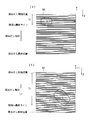
- FIG. 11A and FIG. 11B are schematic diagrams for explaining a procedure for calculating the required time.
- pixels are arranged along a plurality of scanning lines (not shown) extending along the x direction on the imaging element surface IA of the imaging element, and pixel data is read out for each scanning line. Is.
- the scanning line reading order is performed at predetermined intervals in order from the upper scanning line (reading start position) to the lower scanning line (reading final position) shown in FIG. In the example of the CCD image pickup device, the reading order is sequentially performed from the upper left end position of the scanning line to the lower right end position.
- the image generation is performed in order from the upper end side to the lower side, and this is matched with the reading order.
- the reading order is not limited to the above example, and a method of sequentially reading from one end to the other end in the y direction may be used. In this case, the order of image generation is performed sequentially from one end in the y direction in accordance with this.
- step S12 the time required for the reading process is calculated from the reading area ra calculated in step S11.
- the required time is calculated from the position of the scanning line (region ra last line) where the lowest pixel in the readout region ra is located. Specifically, the time from the start of reading of the upper scanning line (reading start position) to the end of reading of the scanning line (region ra last line) in which the lower pixel is located (in FIG. 11A). Symbol Tr).
- the required time Tr varies depending on the position of the lower end of the readout area ra, and the readout area ra shown in FIG. 11B is lower than the imaging element surface IA as compared with FIG. It turns out that Tr becomes long.
- step S13 the control unit 100 outputs a reading start signal rdt to the imaging unit 110 according to the required time Tr calculated in step S12.
- FIG. 12 is a time chart showing the timing of the reading start signal rdt.
- the upper part of the figure shows the operation of the image sensor of the imaging unit 110, and the lower part shows the operation of the control unit 100.
- a vertical synchronization signal Vsync is a synchronization signal from the synchronization signal generation circuit 150, and each frame image signal VD indicates a frame number (f1, f2, etc.).
- the period of the vertical synchronization signal Vsync is 30 Hz (33.3 ms period) in the example shown in the figure, and image data is output at a frame rate of 30 fps in synchronization with this.
- Trm corresponds to the required time Tr calculated in step S12, and is a time obtained by offsetting the required time Tr by a predetermined time.
- the reading start signal rdt output from the control unit 100 to the imaging device (Sensor) of the imaging unit 110 is a time Trm (in the figure, corresponding to the required time Tr with respect to the period of the vertical synchronization signal Vsync). Is the timing of going up by 6 ms, 8 ms, 10 ms, etc.).
- the time when reading from the image sensor in the imaging unit 110 is completed and the time when the input of the image signal VD input from the imaging unit 110 to the control unit 100 in step S21 is completed (reference numerals t1 to t7 in FIG. 12).
- step S22 the coordinates of each pixel on the virtual projection plane VP are converted from the world coordinate system to the camera coordinate system (w2c conversion).
- the transformation of the coordinate system is as described with reference to FIGS. Note that the same w2c conversion is performed in step S11, and if the coordinate conversion is performed for all the pixels of the virtual projection plane VP in step S11, the conversion result in step S11 may be applied as it is in this step. .
- step S23 image processing is performed using the pixel data of the coordinates Gi of the image sensor by performing the processing in step S22 on the image signal input in step S21.
- image generation method there is a four-point interpolation as described below.
- the pixel of the imaging device to be referred to is determined from the coordinates Gi (x ′, y ′) determined by the w2c conversion.
- the coordinates (x, y) of each pixel of the imaging device are determined.
- x and y are integers, but x ′ and y ′ of the coordinates Gi (x ′, y ′) after w2c conversion are not limited to integers and can take real values having a decimal part.
- the pixel data of the pixel of the corresponding image sensor is used as a pixel on the virtual projection plane VP. It can be used as pixel data of an output image corresponding to Gv (X, Y, Z).
- the calculated coordinates Gi are used as pixel data of the output image corresponding to the pixel Gv as four-point interpolation.
- step S24 output processing is performed based on the generated image.
- an output process in the demosaic process, an output image can be obtained by calculating BGR data of each pixel from a signal of a peripheral pixel.
- the demosaic process is, for example, an image sensor composed of pixels arranged in a Bayer array, so that each pixel has only color information for one color, and interpolation processing is performed from information on neighboring pixels to obtain the color for three colors. It is to calculate color information.
- step S25 the control unit 100 functioning as an “image output unit” sends the output image obtained in step S24 to the video memory 104 and causes the display unit 120 to display the output image in synchronization with the synchronization signal. By performing this continuously, a moving image of 30 fps is displayed on the display unit 120.
- the time required for the readout process is calculated from the readout area of the image sensor as described above, and the pixel data is read from the image sensor at the readout start timing set from the required time calculated for each frame.
Landscapes
- Engineering & Computer Science (AREA)
- Multimedia (AREA)
- Signal Processing (AREA)
- Physics & Mathematics (AREA)
- General Physics & Mathematics (AREA)
- Theoretical Computer Science (AREA)
- Studio Devices (AREA)
- Image Processing (AREA)
Abstract
低容量の画像メモリの比較的小規模な回路であっても、処理時間の短縮化を図ることが可能な、画像処理方法及び撮像装置を提供する。複数の画素を有し、所定の順序で読み出しを行う撮像素子と、歪補正係数及び、ワールド座標系の仮想投影面の位置若しくはサイズにより決定される歪補正パラメータを設定する歪補正パラメータ生成部と、前記設定部で設定された仮想投影面の各画素のワールド座標系における座標を、前記歪補正パラメータに基づいてカメラ座標系に変換し、変換したカメラ座標系における座標及び前記撮像素子から読み出した複数の画素データに基づいて、前記仮想投影面での画像データを算出する歪補正処理部と、を有し、前記歪補正処理部は、前記撮像素子の読み出し処理に係る所要時間を算出し、1フレーム毎に算出した所要時間から読み出し開始タイミングで前記撮像素子から画素データの読み出しを行う。
Description
本願発明は、集光レンズを含む光学系を介して撮像素子により撮像された動画像の歪み補正処理を行う、画像処理方法及び撮像装置に関する。
一般に、広角レンズあるいは魚眼レンズのような焦点距離の短いレンズや画角の大きなレンズを備えた光学系により撮影した画像は歪曲を伴うので、歪曲を補正する画像処理を行う。特許文献1には従来技術の補正方法として、焦点距離の短いレンズを使用して撮像された撮像画像に生じる歪曲を、レンズの補正用のパラメータを用いて補正する方法が開示されている。
特許文献2では、画像メモリの低容量化を目的として、撮像素子側の解像度に対応した画像データのデータ量に依存せずに、出力画像データの解像度に応じた画像メモリで画像処理する画像データ処理装置が開示されている。この画像データ処理装置では、手ぶれ補正処理やこれとともに歪補正処理を行う際に水平手ぶれ補正と垂直手ぶれ補正の2つの処理に分けて、それぞれ第1メモリ、第2メモリに書き込みを行っている。第1メモリには、出力画像の解像度に合わせて解像度変換した後の水平手ぶれ補正処理後の画像をライン毎に順次記憶させ、垂直手ぶれ補正が可能となる複数の水平ラインの画像が蓄積された段階で第1メモリから読みだしを行って垂直手ぶれ補正を行い、処理後の画像を第2メモリに記憶させている。
特許文献1に開示されたように、レンズで得た撮像画像を画像処理装置としてハード化した場合に処理時間が長くなり、回路規模が増大してしまい、コストが嵩んでしまうという問題があった。
また、歪み補正処理をした後の画像は、視野角が狭くなるので広い領域を一度に認識することは難しくなる。歪み補正処理をおこなわない画像では、視野角は広くなるがその反面、被写体が歪むことにより距離感や大きさの認識が難しくなる。
特許文献2では、水平方向と垂直方向の補正処理を分離して2回に渡って行っており、垂直手ぶれ補正を行うためには、複数の水平ラインの画像データを処理している。焦点距離の短いレンズを用いた光学系を用いたカメラから得られた画像データにおいては、歪曲による垂直方向のずれ量も撮像素子の位置(主に光学中心からの距離)に応じて変化するために、その分のマージンを見込んだ水平ライン数の画像データをまとめて処理する必要があり、処理も複雑となる。
本願発明はこのような問題に鑑み、低容量の画像メモリの比較的小規模な回路であっても、処理時間の短縮化を図ること、及び、被写体の正確な認識を図ることが可能な、画像処理方法及び撮像装置を提供することを目的とする。
上記の目的は、下記に記載する発明により達成される。
1.光学系を介して複数の画素を有し、所定の順序で読み出しを行う撮像素子に受光して得られた複数の画素データを用いて歪み補正処理した動画像データを得る画像処理方法において、
歪補正係数及び、ワールド座標系の仮想投影面の位置若しくはサイズにより決定される歪補正パラメータを設定する第1ステップと、
設定された歪補正パラメータにより前記撮像素子の読み出し領域を算出する第2ステップと、
算出した前記読み出し領域から前記撮像素子の読み出し処理に係る所要時間を算出し、1フレーム毎に算出した所要時間から設定した読み出し開始タイミングで前記撮像素子から画素データの読み出しを行う第3ステップと、
前記第3ステップで読み出した画素データと、前記第1ステップで設定された歪補正パラメータを用いて前記仮想投影面の各画素をカメラ座標系に変換し、変換したカメラ座標系における座標及び前記複数の画素データに基づいて前記第1ステップで設定された仮想投影面の画像データを算出する第4ステップと、
を有することを特徴とする画像処理方法。
歪補正係数及び、ワールド座標系の仮想投影面の位置若しくはサイズにより決定される歪補正パラメータを設定する第1ステップと、
設定された歪補正パラメータにより前記撮像素子の読み出し領域を算出する第2ステップと、
算出した前記読み出し領域から前記撮像素子の読み出し処理に係る所要時間を算出し、1フレーム毎に算出した所要時間から設定した読み出し開始タイミングで前記撮像素子から画素データの読み出しを行う第3ステップと、
前記第3ステップで読み出した画素データと、前記第1ステップで設定された歪補正パラメータを用いて前記仮想投影面の各画素をカメラ座標系に変換し、変換したカメラ座標系における座標及び前記複数の画素データに基づいて前記第1ステップで設定された仮想投影面の画像データを算出する第4ステップと、
を有することを特徴とする画像処理方法。
2.前記第1ステップで設定される歪補正パラメータは、フレーム毎に変化させるパラメータであることを特徴とする前記1に記載の画像処理方法。
3.前記第1ステップで設定される歪補正パラメータは、仮想投影面の位置をフレーム毎に移動させるパラメータ及びレンズパラメータをフレーム毎に変化させるパラメータの少なくとも何れか一方であることを特徴とする前記2に記載の画像処理方法。
4.光学系と、
複数の画素を有し、所定の順序で読み出しを行う撮像素子と、
ワールド座標系における仮想投影面の位置及びサイズを設定する設定部と、
歪補正係数及び、ワールド座標系の仮想投影面の位置若しくはサイズにより決定される歪補正パラメータを設定する歪補正パラメータ生成部と、
前記設定部で設定された仮想投影面の各画素のワールド座標系における座標を、前記歪補正パラメータに基づいてカメラ座標系に変換し、変換したカメラ座標系における座標及び前記撮像素子から読み出した複数の画素データに基づいて、前記仮想投影面での画像データを算出する歪補正処理部と、
算出した画像データを動画像として出力する画像出力部と、
を有し、
前記歪補正処理部は、設定された歪補正パラメータにより前記撮像素子の読み出し領域を算出し、算出した読み出し領域から前記撮像素子の読み出し処理に係る所要時間を算出し、1フレーム毎に算出した所要時間から読み出し開始タイミングで前記撮像素子から画素データの読み出しを行うことを特徴とする撮像装置。
複数の画素を有し、所定の順序で読み出しを行う撮像素子と、
ワールド座標系における仮想投影面の位置及びサイズを設定する設定部と、
歪補正係数及び、ワールド座標系の仮想投影面の位置若しくはサイズにより決定される歪補正パラメータを設定する歪補正パラメータ生成部と、
前記設定部で設定された仮想投影面の各画素のワールド座標系における座標を、前記歪補正パラメータに基づいてカメラ座標系に変換し、変換したカメラ座標系における座標及び前記撮像素子から読み出した複数の画素データに基づいて、前記仮想投影面での画像データを算出する歪補正処理部と、
算出した画像データを動画像として出力する画像出力部と、
を有し、
前記歪補正処理部は、設定された歪補正パラメータにより前記撮像素子の読み出し領域を算出し、算出した読み出し領域から前記撮像素子の読み出し処理に係る所要時間を算出し、1フレーム毎に算出した所要時間から読み出し開始タイミングで前記撮像素子から画素データの読み出しを行うことを特徴とする撮像装置。
5.前記歪補正パラメータ生成部で設定される歪補正パラメータは、フレーム毎に変化させるパラメータであることを特徴とする前記4に記載の撮像装置。
6.前記歪補正パラメータは、仮想投影面の位置をフレーム毎に移動させるパラメータ及びレンズパラメータをフレーム毎に変化させるパラメータの少なくとも何れか一方であることを特徴とする前記5に記載の撮像装置。
本願発明によれば、仮想投影面の各画素をカメラ座標系に変換し、変換したカメラ座標系における座標及び撮像素子の複数の画素データに基づいて、仮想投影面の画像データを算出するとともに、撮像素子の読み出し領域を算出し、算出した読み出し領域から撮像素子の読み出し処理に係る所要時間を算出し、1フレーム毎に算出した所要時間から設定した読み出し開始タイミングで撮像素子から画素データの読み出しを行うようにすることにより、低容量の画像メモリの比較的小規模な回路であっても、処理時間の短縮化を図ることが可能な、画像処理方法及び撮像装置を提供することが可能となる。
また、更に歪補正パラメータをフレーム毎に変化させることにより、被写体の正確な認識を図ることが可能となる。
本発明を実施の形態に基づいて説明するが、本発明は該実施の形態に限られない。
図1は、本実施形態に係る歪補正を説明する模式図である。図1において、X、Y、Zはワールド座標系であり、原点Oはレンズ中心である。Zは光軸、XY平面はレンズ中心Oを通るレンズ中心面LCを含んでいる。点Pはワールド座標系XYZにおける被写体の物点である。θはレンズ中心(原点O)における光軸(Z軸に一致)に対する入射角である。
x、yはカメラ座標系であり、xy平面は撮像素子面IAに対応する。oは光学中心であり光学系の光軸Zと撮像素子面との交点である。点pはカメラ座標系における撮像素子面上の点であり、物点Pをレンズの物理的特性に基づくパラメータ(以下、「レンズパラメータ」という。例えば焦点距離、非球面係数、有効径等の情報)を用いて生成した仮想投影面VPの各画素の光軸Zからの位置と像高とを対応づけた歪補正係数を用いてカメラ座標系に変換したものである。
VPは仮想投影面である。仮想投影面VPは光学系のレンズ位置(レンズ中心面LC)に対して撮像素子(及び撮像素子面IA)とは反対側に設定される。仮想投影面VPは、ユーザによるユーザ操作部130(図3参照)への指示に基づいて、位置変更及びサイズの変更を行うことが可能である。位置変更についての詳細は後述する。
初期状態(初期の位置設定のこと、以下同様)において仮想投影面VPは、所定サイズでレンズ中心面LCと平行(XY方向)の所定位置(Z方向)に配置され、仮想投影面VPの中心ovはZ軸上に位置している。Gvは物点Pが仮想投影面VP上に投影された点であり、物点Pとレンズ中心Oを通る直線と仮想投影面VPとの交点である。
[仮想投影面VPの位置変更による視点変換の例]
仮想投影面VPは位置変更させることが可能である。ここで「位置変更」とは、次に示す様に仮想投影面VPをXY平面上で平行移動させる場合のみならず、XY平面に対する角度変更(姿勢変更ともいう)をも含む概念である。位置変更に伴い視点変換がなされる。
仮想投影面VPは位置変更させることが可能である。ここで「位置変更」とは、次に示す様に仮想投影面VPをXY平面上で平行移動させる場合のみならず、XY平面に対する角度変更(姿勢変更ともいう)をも含む概念である。位置変更に伴い視点変換がなされる。
図2は、カメラ座標系の画像中心oを回転中心(若しくは移動中心)として仮想投影面VP0の位置を変更する例である。図2に示すように画像中心oを回転中心としてx軸回りの回転が実pitch(tilt:チルトともいう)であり、y軸回りの回転が実yaw(pan:パンともいう)、Z軸回りの回転が実rollである。
図3は、入力された回転量の設定値に基づいて仮想投影面VP0の中心ovを回転中心として仮想投影面VPの位置を変更する例である。仮想投影面VP0上の直交する関係となる2軸の一方をYaw-axis、他方をP-axisとして設定する。両者は中心ovを通る軸であり、中心ovを回転中心としてYaw-axis回りの回転を仮想yaw回転、P-axis回りの回転を仮想pitch回転という。以下においては仮想カメラCa0を回転あるいは位置変更させたことに相当する視点変換が行われる。
図4は、カメラ座標系の画像中心oを移動中心として仮想投影面VPの位置を変更する例である。これらの例においては仮想カメラCa0を仮想投影面VPとともに平行移動させたことに相当する視点変換が行われる。
図5は、実yaw移動により、仮想投影面VPを初期位置(VP0)から移動させた状態(VP1)の仮想投影面を示す例である。
[ブロック図]
図6は、撮像装置の概略構成を示すブロック図である。撮影装置は、撮像ユニット110、制御部100、表示部120、ユーザ操作部130を備えている。
図6は、撮像装置の概略構成を示すブロック図である。撮影装置は、撮像ユニット110、制御部100、表示部120、ユーザ操作部130を備えている。
撮像ユニット110は、短焦点のレンズ、撮像素子等から構成される。本実施形態においては、レンズとしては例えば広角レンズ、魚眼レンズがある。撮像素子としては、例えば複数の画素(受光素子)が格子状に配置され、それぞれにスイッチング素子が配置されたX-Yアドレス型のC-MOS撮像素子がある。各画素に配置されたスイッチング素子には走査線(x方向)と信号線(y方向)がそれぞれ接続されており、走査線に接続している画素を一群として所定の順序で信号線から画素データの読み出しを行って画像データの出力を行う。
制御部100では、ユーザ操作部130への入力指示に基づいて仮想投影面VPの位置、サイズの設定、及び歪み補正強度、歪み補正の変化速度及び変化の上下限の設定を行うことができる。
同期信号生成回路150では、水平同期信号(Hsync)、垂直同期信号(Vsync)、基準クロック(clk)が生成され、これらの信号は、制御部100の歪補正処理部101、歪補正パラメータ生成部102、ビデオメモリ104の各部に送られる。
仮想投影面VPの位置、サイズの設定をすることにより、パンチ、チルトや、ズームイン、ズームアウト等のカメラの視点変更が行われることになり、これらの設定は本願において「設定部」として機能する歪補正パラメータ生成部102により変換されて歪補正パラメータとして歪補正処理部101に送られる。
ROM108には、撮像ユニット110の実レンズの物理特性に基づくレンズパラメータと、歪み補正を行わない場合(ピンホールレンズに相当する)のレンズパラメータが記憶されている。
ROM108に記憶されているレンズパラメータの情報により歪補正係数が生成され、当該歪補正係数の変化速度、変化幅の設定情報、及び仮想投影面VPの位置の変化速度、変化幅の設定情報はLUT生成部103に送られる。
歪補正処理部101では、歪処理部101aと、撮像同期信号タイミング演算部101bとを備えている。撮像同期信号タイミング演算部101bでは後述の処理により撮像素子の読み取りに必要な所要時間を演算する。所要時間はフレーム毎に演算され各フレームで異なる値を取り得る。歪補正処理部101では、算出した所要時間に基づいて、同期信号生成回路150から入力した(所定間隔で発信される)垂直同期信号Vsyncに対して所要時間に対応する時間だけ遡上させたタイミングの読取開始信号rdtを撮像ユニット110に出力する。
歪補正処理部101では、撮像ユニット110からの入力画像から、LUT生成部103から取得したLUTを用いて歪み補正処理後の出力画像を生成する。ここで用いるLUTは、LUT生成部103により生成されたものであり、歪補正パラメータ生成部102から送られた歪補正パラメータを用いて計算した、座標変換により対応付けられた仮想投影面VPの各画素と撮影素子の画素との対応関係を記述したものである。出力画像は、ビデオメモリ104に書き込まれ、同期信号生成回路150からの同期信号に合わせて1フレーム毎に表示部120に送られる。
表示部120は、液晶ディスプレイ等の表示画面を備え、送られた出力画像を逐次、表示画面に表示させる。
ユーザ操作部130は、キーボード、マウス、あるいは表示用の液晶ディスプレイに重畳して配置したタッチパネルを備え、ユーザの入力操作を受け付ける。
[仮想投影面VPの画素と、撮像素子の画素との対応関係]
次に、ワールド座標系の仮想投影面VPの各画素をカメラ座標系に変換する手順について説明する。すなわち、これはレンズパラメータに基づいてワールド座標の位置がカメラ座標のどの座標位置に対応するかを当てはめる座標変換を行うものであり、この際に歪み補正及び、仮想投影面VPの位置の計算にともなう回転、平行移動、拡大、縮小等の視点変換が併せて行われる。
次に、ワールド座標系の仮想投影面VPの各画素をカメラ座標系に変換する手順について説明する。すなわち、これはレンズパラメータに基づいてワールド座標の位置がカメラ座標のどの座標位置に対応するかを当てはめる座標変換を行うものであり、この際に歪み補正及び、仮想投影面VPの位置の計算にともなう回転、平行移動、拡大、縮小等の視点変換が併せて行われる。
図7は、座標系を説明する模式図である。図7に示すようにワールド座標系における仮想投影面VPの4隅の点A(0,0,Za)、点B(0,479,Zb)、点C(639,479,Zc)、点D(639,0,Zd)で囲まれる平面を等間隔で640×480
pixelの画素Gv(総画素数30.7万)に分割し、全ての画素Gvそれぞれのワールド座標系における座標を取得する。なお同図におけるX、Y座標の値は例示であり、理解を容易にするために、A点のX、Y座標をゼロとして表示している。
pixelの画素Gv(総画素数30.7万)に分割し、全ての画素Gvそれぞれのワールド座標系における座標を取得する。なお同図におけるX、Y座標の値は例示であり、理解を容易にするために、A点のX、Y座標をゼロとして表示している。
画素Gvのワールド座標系での座標と、後述する歪補正パラメータ生成部で設定されたレンズパラメータに基づく歪補正係数から、撮像素子面IAでの対応するカメラ座標系での座標Gi(x’,y’)を算出する。具体的には、当該歪補正係数と各画素Gvの座標から得られる光軸Zに対する入射角度θにより算出している(参考文献:国際公開第2010/032720号)。
図8は、カメラ座標系xyと撮像素子面IAとの対応関係を示す図である。図8において点a~dは、図7の点A~Dを、レンズパラメータに対応した歪補正係数に基づいてカメラ座標系に変換したものである。なお図7では点A~Dで囲まれる仮想投影面VPは矩形の平面であるが、図8においてカメラ座標系に座標変換した後の点a~dで囲まれる読み出し領域raは(仮想投影面VPの位置に対応して)歪んだ形状となる。なお同図においては樽型形状に歪んだ例を示しているが、光学系の特性により糸巻型、陣笠型(中央では樽型で端部では直線あるいは糸巻型に変化する形状)の歪みとなる場合もある。
図9は、像高hと入射角θとの関係を示す模式図である。被写体(物点P)の撮像素子面IA上の像高(光軸Zからの距離)は、入射角θと歪補正係数で決定される。piは歪み補正を行わないレンズパラメータにより決定される撮像素子面IA上の物点Pの結像位置であり、光軸からの距離(像高)はピンホールカメラのように、入射角θの正接関数に比例する。Giは実レンズの物理特性に基づくレンズパラメータにより決定された歪補正係数を用いて算出される歪み補正後の結像位置であり、その際の像高はhである。
このようにして撮影素子面IA上におけるカメラ座標系の座標は、レンズパラメータに基づく歪補正係数、及びワールド座標系における仮想投影面VPの位置により決定される。
[制御フロー]
図10は、本実施形態の制御フローを示す図である。図10(a)は全体制御フロー、図10(b)は図10(a)のステップS10のサブルーチンを説明する図である。
図10は、本実施形態の制御フローを示す図である。図10(a)は全体制御フロー、図10(b)は図10(a)のステップS10のサブルーチンを説明する図である。
図10(a)のステップS10では、歪補正パラメータの設定を行う。歪補正パラメータは、(1)歪補正係数と、(2)視野角、実yaw、仮想yaw、実pitch、仮想pitch等の仮想投影面の位置設定とからなる。当該歪補正パラメータの設定を行うステップS10のフローは図10(b)に示すようにステップS101に示す仮想投影面VPの位置設定と、ステップS102に示すレンズパラメータの設定とからなる。設定は、ユーザ操作部130の入力により歪補正パラメータ生成部により行われる。これらの設定により設定されたパラメータとしては以下の4つの態様がある。
(P1)仮想投影面の位置設定が1つで、レンズパラメータが1つ
(P2)仮想投影面の位置設定が2つで、レンズパラメータが1つ
(P3)仮想投影面の位置設定が1つで、レンズパラメータが2つ
(P4)仮想投影面の位置設定が2つで、レンズパラメータが2つ。
(P1)仮想投影面の位置設定が1つで、レンズパラメータが1つ
(P2)仮想投影面の位置設定が2つで、レンズパラメータが1つ
(P3)仮想投影面の位置設定が1つで、レンズパラメータが2つ
(P4)仮想投影面の位置設定が2つで、レンズパラメータが2つ。
レンズパラメータとしては、ROM108に記憶されている2つのレンズパラメータの何れかを選択する。2つのレンズパラメータを設定した場合には、レンズパラメータに基づく歪補正係数の変化速度、変化幅の設定を行う。仮想投影面VPの位置設定も同様に、2つ又はこれ以上の複数箇所の位置を設定した場合には、位置の変化速度、変化幅の設定を行う。
例えば、上記(P4)の態様において、始点として仮想投影面VPの第1位置V1、レンズパラメータL1、終点として仮想投影面VPの第2位置V1、レンズパラメータL2を設定し、これらを補間する位置V3、レンズパラメータL3を以下の式(1)、(2)により算出するようにし、変化速度のパラメータVCRatio、DistRatioをそれぞれ数秒周期
で0~100%の間を繰り返すように設定する。
で0~100%の間を繰り返すように設定する。
V3=VCRatio/100×V1+(1-VCRatio/100)×V2 式(1)
(但し、0≦VCRatio/100≦1)
L3=DistRatio/100×L1+(1-DistRatio/100)×L2 式(2)
(但し、0≦DistRatio/100≦1)
第1位置V1の例としては図1等に示す初期位置であり、第2位置V2の例としては実pitch-45度(図2参照)と仮想pitch-45度(図3参照)を組み合わせた位置(レンズ中心からは俯角方向)が挙げられる。レンズパラメータL1としては実レンズの物理特性に基づくレンズパラメータが、レンズパラメータL2としては歪み補正を行わない(ピンホールレンズに相当する)レンズパラメータが挙げられる。例えば魚眼レンズを用いた例であればレンズパラメータL1はtan関数となり、これが1次関数のレンパラメータL2まで連続的に変化してゆくことになる。なお仮想投影面VPの位置変更に伴い、サイズの設定も行うようにしてもよい。
(但し、0≦VCRatio/100≦1)
L3=DistRatio/100×L1+(1-DistRatio/100)×L2 式(2)
(但し、0≦DistRatio/100≦1)
第1位置V1の例としては図1等に示す初期位置であり、第2位置V2の例としては実pitch-45度(図2参照)と仮想pitch-45度(図3参照)を組み合わせた位置(レンズ中心からは俯角方向)が挙げられる。レンズパラメータL1としては実レンズの物理特性に基づくレンズパラメータが、レンズパラメータL2としては歪み補正を行わない(ピンホールレンズに相当する)レンズパラメータが挙げられる。例えば魚眼レンズを用いた例であればレンズパラメータL1はtan関数となり、これが1次関数のレンパラメータL2まで連続的に変化してゆくことになる。なお仮想投影面VPの位置変更に伴い、サイズの設定も行うようにしてもよい。
ステップS11では撮像素子の読みだし領域を算出する。読みだし領域は、ステップS10で設定された仮想投影面VPの位置、サイズやレンズパラメータにより定義される歪補正パラメータにより決定されるものであり、前述の図7~図9で説明したワールド座標系からカメラ座標系へ座標変換(以下「w2c変換」ともいう)を行うことにより行う。歪補正パラメータが固定(前述の(P1)の態様)であれば撮像素子の読みだし領域は固定であり、歪補正パラメータがフレーム毎に変化するのであれば(前述の(P2)~(P4)の態様)でフレーム毎に撮像素子の読みだし領域は変化する。具体的には、仮想投影面VPの位置が光軸から外れるほどワールド座標系からカメラ座標系に変換した後の撮像素子面IA上の位置も画像中心oから遠ざかることになる。
なお、ステップS11では仮想投影面VPの全画素についてw2c変換しても良いが、処理を簡略化するために、後述の所要時間の算出に必要な領域(撮像素子面IAで図示下方の領域)に限定したり、仮想投影面VPの外周部分に限定したりしても良い。
ステップS12では、読みだし領域の端点から撮像素子の読みだしにかかる所要時間を算出する。図11(a)、図11(b)は、所要時間の算出手順を説明する模式図である。同図に示すように撮像素子の撮像素子面IAには、x方向に沿って伸びる複数の走査線(不図示)に沿って画素が配置されており、走査線毎に画素データの読み出しを行うものである。走査線の読み出し順序は、同図に示す上端の走査線(読み出し開始位置)から下端の走査線(読み出し最終位置)まで順に所定間隔で行われる。なおCCD撮像素子の例であれば、読み出し順序は走査線の上端左端位置から下端右端位置まで順に行われることになる。また本実施形態では、画像の生成を上端側から下方に向けて順に行っておりこれは読み出し順に合わせている。読み出し順は、上記例に限られずy方向の一方の端から他方端に向けて順に行う方式でも良い。この場合は画像生成の順はこれに合わせてy方向の一方の端から順に行うことになる。
図11(a)、図11(b)には読み出し領域raを示している。図11(a)、図11(b)では、歪補正パラメータが異なるために読み出し領域raの範囲の位置、サイズも異なっている。ステップS12では、ステップS11で算出した読み出し領域raから読み出し処理に係る所要時間を算出する。所要時間は、読み出し領域ra内の最も下端の画素が位置する走査線(領域ra最終ライン)の位置から算出する。具体的には上端の走査線(読み出し開始位置)の読み出しを開始してから、下端の画素が位置する走査線(領域ra最終ライン)の読み出しが終了するまでの時間(図11(a)の符号Tr)である。
所要時間Trは、読み出し領域raの下端の位置により変化するものであり、図11(a)に比べて図11(b)に示す読み出し領域raは、撮像素子面IAの下方にあるので所要時間Trは長くなることが分かる。
ステップS13では、制御部100はステップS12で算出した所要時間Trに応じて、撮像ユニット110に読取開始信号rdtを出力する。
図12は、読取開始信号rdtのタイミングを示すタイムチャートである。同図の上段は、撮像ユニット110の撮像素子の動作を、下段は制御部100の動作を示している。同図において、垂直同期信号Vsyncは同期信号生成回路150からの同期信号であり、1フレームの画像信号VDにはそれぞれフレームの番号(f1、f2等)を示している。垂直同期信号Vsyncの周期としては同図に示す例で30Hz(33.3ms周期)であり、これに同期してフレームレート30fpsで画像データの出力を行っている。
同図においてTrmは、ステップS12で算出した所要時間Trに対応しており、当該所要時間Trに対して所定時間分のオフセットを行った時間である。同図に示すように制御部100から撮像ユニット110の撮像素子(Senser)へ出力される読取開始信号rdtは、垂直同期信号Vsyncの周期に対して所要時間Trに対応する時間Trm(同図においては、6ms、8ms、10ms等)だけ遡上させたタイミングとなっている。
これにより、撮像ユニット110における撮像素子からの読み取りが終了する時間、及びステップS21で撮像ユニット110から制御部100に入力される画像信号VDの入力が終了する時間(図12の符号t1~t7)は、垂直同期信号Vsyncに対して常に一定のタイミングとなる。このため、垂直同期信号Vsyncと同期をとるためのタイミング処理が不要となる。
ステップS22では、仮想投影面VPの各画素の座標をワールド座標系からカメラ座標系に変換する(w2c変換)。座標系の変換は、前述の図7~図9で説明したとおりである。なおステップS11でも同様のw2c変換を行っており、ステップS11で仮想投影面VPの全画素について座標変換を行ったのであれば当該ステップでは、ステップS11の変換結果をそのまま適用するようにしても良い。
ステップS23では、ステップS21で入力された画像信号に対して、ステップS22での処理を行うことにより撮像素子の座標Giの画素データを用いて画像生成が行われる。画像生成の方法としては以下に説明するように4点補間がある。
図7に示したようにw2c変換により決定される座標Gi(x’,y’)から参照する撮像素子の画素を決定するが、この際に撮像素子の各画素の座標(x,y)におけるx、yは整数であるが、w2c変換後の座標Gi(x’,y’)のx’、y’は整数とは限らず小数部分を持つ実数値を取り得る。x’、y’が整数で、座標Gi(x’,y’)と撮像素子の画素の位置とが一致する場合には、対応する撮像素子の画素の画素データを仮想投影面VP上の画素Gv(X,Y,Z)に対応する出力画像の画素データとして用いることが可能である。一方で、x’、y’が整数でなくx’、y’とx、yとが一致しない場合には4点補間として、画素Gvに対応する出力画像の画素データとして、算出された座標Gi(x’,y’)周辺の画素、座標Gi(x’,y’)の位置に近接する上位4箇所の画素の画素データを用いて、これらの単純平均値あるいは、座標Gi(x’,y’)に対する距離により近接する4箇所の画素に対して重み付けをして算出した画素データを用いる。なお4点補間に限られず、周辺の箇所としては1箇所の単純補間や、16箇所若しくはそれ以上を用いる多点補間であってもよい。
ステップS24では生成された画像に基づいて出力処理を行う。出力処理としてはデモザイク処理において、周辺画素の信号から各画素のBGRデータの演算を行って出力画像を得ることができる。デモザイク処理とは、例えば撮像素子がベイヤー配列で並んだ画素で構成されることにより各画素が1色分の色情報しか持たない場合に、周辺画素の情報から補間処理することにより3色分の色情報を算出することである。
ステップS25では、「画像出力部」として機能する制御部100は、ステップS24で得られた出力画像をビデオメモリ104に送り、同期信号に同期させて表示部120に表示させる。これを連続して行うことにより表示部120には、30fpsの動画像が表示される。
本実施形態においては、このように撮像素子の読み出し領域から、読み出し処理に係る所要時間を算出し、1フレーム毎に算出した所要時間から設定した読み出し開始タイミングで撮像素子から画素データの読み出しを行うようにすることにより、1フレーム毎の処理タイミングを一定にすることができ、引いては複雑なタイミング処理も不要となる。
また、常に処理タイミングを一定にすることにより、ライン毎の処理を連続して行うことができるので、撮像素子からの入力画像を1フレーム分蓄積する必要がなくこれにより必要なメモリ容量が削減できる。
なお、本発明は、本明細書に記載の実施の形態に限定されるものではなく、他の実施の形態や変形例を含むことは、本明細書に記載された実施の形態や技術的思想から本分野の当業者にとって明らかである。
100 制御部
101 歪補正処理部
101a 歪処理部
101b 撮像同期信号タイミング演算部
102 歪補正パラメータ生成部
103 LUT生成部
104 ビデオメモリ
110 撮像ユニット
120 表示部
130 ユーザ操作部
150 同期信号生成回路
VP 仮想投影面
LC レンズ中心面
IA 撮像素子面
O レンズ中心
o 光学中心
101 歪補正処理部
101a 歪処理部
101b 撮像同期信号タイミング演算部
102 歪補正パラメータ生成部
103 LUT生成部
104 ビデオメモリ
110 撮像ユニット
120 表示部
130 ユーザ操作部
150 同期信号生成回路
VP 仮想投影面
LC レンズ中心面
IA 撮像素子面
O レンズ中心
o 光学中心
Claims (6)
- 光学系を介して複数の画素を有し、所定の順序で読み出しを行う撮像素子に受光して得られた複数の画素データを用いて歪み補正処理した動画像データを得る画像処理方法において、
歪補正係数及び、ワールド座標系の仮想投影面の位置若しくはサイズにより決定される歪補正パラメータを設定する第1ステップと、
設定された歪補正パラメータにより前記撮像素子の読み出し領域を算出する第2ステップと、
算出した前記読み出し領域から前記撮像素子の読み出し処理に係る所要時間を算出し、1フレーム毎に算出した所要時間から設定した読み出し開始タイミングで前記撮像素子から画素データの読み出しを行う第3ステップと、
前記第3ステップで読み出した画素データと、前記第1ステップで設定された歪補正パラメータを用いて前記仮想投影面の各画素をカメラ座標系に変換し、変換したカメラ座標系における座標及び前記複数の画素データに基づいて前記第1ステップで設定された仮想投影面の画像データを算出する第4ステップと、
を有することを特徴とする画像処理方法。 - 前記第1ステップで設定される歪補正パラメータは、フレーム毎に変化させるパラメータであることを特徴とする請求項1に記載の画像処理方法。
- 前記第1ステップで設定される歪補正パラメータは、仮想投影面の位置をフレーム毎に移動させるパラメータ及びレンズパラメータをフレーム毎に変化させるパラメータの少なくとも何れか一方であることを特徴とする請求項2に記載の画像処理方法。
- 光学系と、
複数の画素を有し、所定の順序で読み出しを行う撮像素子と、
ワールド座標系における仮想投影面の位置及びサイズを設定する設定部と、
歪補正係数及び、ワールド座標系の仮想投影面の位置若しくはサイズにより決定される歪補正パラメータを設定する歪補正パラメータ生成部と、
前記設定部で設定された仮想投影面の各画素のワールド座標系における座標を、前記歪補正パラメータに基づいてカメラ座標系に変換し、変換したカメラ座標系における座標及び前記撮像素子から読み出した複数の画素データに基づいて、前記仮想投影面での画像データを算出する歪補正処理部と、
算出した画像データを動画像として出力する画像出力部と、
を有し、
前記歪補正処理部は、設定された歪補正パラメータにより前記撮像素子の読み出し領域を算出し、算出した読み出し領域から前記撮像素子の読み出し処理に係る所要時間を算出し、1フレーム毎に算出した所要時間から読み出し開始タイミングで前記撮像素子から画素データの読み出しを行うことを特徴とする撮像装置。 - 前記歪補正パラメータ生成部で設定される歪補正パラメータは、フレーム毎に変化させるパラメータであることを特徴とする請求項4に記載の撮像装置。
- 前記歪補正パラメータは、仮想投影面の位置をフレーム毎に移動させるパラメータ及びレンズパラメータをフレーム毎に変化させるパラメータの少なくとも何れか一方であることを特徴とする請求項5に記載の撮像装置。
Priority Applications (1)
| Application Number | Priority Date | Filing Date | Title |
|---|---|---|---|
| JP2012547798A JPWO2012077544A1 (ja) | 2010-12-07 | 2011-11-30 | 画像処理方法及び撮像装置 |
Applications Claiming Priority (2)
| Application Number | Priority Date | Filing Date | Title |
|---|---|---|---|
| JP2010-272320 | 2010-12-07 | ||
| JP2010272320 | 2010-12-07 |
Publications (1)
| Publication Number | Publication Date |
|---|---|
| WO2012077544A1 true WO2012077544A1 (ja) | 2012-06-14 |
Family
ID=46207035
Family Applications (1)
| Application Number | Title | Priority Date | Filing Date |
|---|---|---|---|
| PCT/JP2011/077617 Ceased WO2012077544A1 (ja) | 2010-12-07 | 2011-11-30 | 画像処理方法及び撮像装置 |
Country Status (2)
| Country | Link |
|---|---|
| JP (1) | JPWO2012077544A1 (ja) |
| WO (1) | WO2012077544A1 (ja) |
Citations (1)
| Publication number | Priority date | Publication date | Assignee | Title |
|---|---|---|---|---|
| WO2007108081A1 (ja) * | 2006-03-20 | 2007-09-27 | Fujitsu Limited | 撮影装置、撮影方法及びプログラム、撮影装置のテーブル作成装置及び方法、映像処理装置及び方法 |
-
2011
- 2011-11-30 WO PCT/JP2011/077617 patent/WO2012077544A1/ja not_active Ceased
- 2011-11-30 JP JP2012547798A patent/JPWO2012077544A1/ja active Pending
Patent Citations (1)
| Publication number | Priority date | Publication date | Assignee | Title |
|---|---|---|---|---|
| WO2007108081A1 (ja) * | 2006-03-20 | 2007-09-27 | Fujitsu Limited | 撮影装置、撮影方法及びプログラム、撮影装置のテーブル作成装置及び方法、映像処理装置及び方法 |
Also Published As
| Publication number | Publication date |
|---|---|
| JPWO2012077544A1 (ja) | 2014-05-19 |
Similar Documents
| Publication | Publication Date | Title |
|---|---|---|
| US8379976B2 (en) | Image processing apparatus and method and a computer-readable recording medium on which an image processing program is stored | |
| JP6702323B2 (ja) | カメラモジュール、固体撮像素子、電子機器、および撮像方法 | |
| JP5744418B2 (ja) | 投影装置及び投影方法 | |
| US8036482B2 (en) | Image processing apparatus and method, program, and recording medium | |
| CN103283214B (zh) | 摄像机、畸变校正装置以及畸变校正方法 | |
| JP6041651B2 (ja) | 画像処理装置、画像処理方法及びプログラム | |
| WO2012060269A1 (ja) | 画像処理方法、画像処理装置及び撮像装置 | |
| JP2010288063A (ja) | プロジェクター、プログラム、情報記憶媒体および台形歪み補正方法 | |
| US8462222B2 (en) | Image processing method and device, and imaging apparatus using the image processing device | |
| JP2004272578A (ja) | 撮像装置及び歪み補正方法 | |
| JP2013005393A (ja) | 広角歪補正処理を有する画像処理方法、画像処理装置及び撮像装置 | |
| JP6236908B2 (ja) | 撮像装置、撮像システムおよび撮像方法 | |
| JP5393877B2 (ja) | 撮像装置および集積回路 | |
| JP5682473B2 (ja) | 広角歪補正処理を有する画像処理方法、画像処理装置及び撮像装置 | |
| JPWO2012056982A1 (ja) | 画像処理方法、画像処理装置及び撮像装置 | |
| JP5521641B2 (ja) | 画像処理用データの圧縮方法および圧縮装置とこれを備えた撮像装置 | |
| JPWO2011161746A1 (ja) | 画像処理方法、プログラム、画像処理装置及び撮像装置 | |
| JPWO2012060271A1 (ja) | 画像処理方法、画像処理装置及び撮像装置 | |
| WO2012081400A1 (ja) | 画像処理方法、画像処理装置及び撮像装置 | |
| WO2012077544A1 (ja) | 画像処理方法及び撮像装置 | |
| JP2004282712A (ja) | 調整装置 | |
| JP2007158639A (ja) | 車両運転支援装置 | |
| JP2007189361A (ja) | イメージセンサおよびこれを用いたカメラ | |
| JP2012060447A (ja) | 画像処理装置、撮像装置、及び画像処理方法 | |
| JP2013005392A (ja) | 広角歪補正処理を有する画像処理方法、画像処理装置及び撮像装置 |
Legal Events
| Date | Code | Title | Description |
|---|---|---|---|
| 121 | Ep: the epo has been informed by wipo that ep was designated in this application |
Ref document number: 11846619 Country of ref document: EP Kind code of ref document: A1 |
|
| ENP | Entry into the national phase |
Ref document number: 2012547798 Country of ref document: JP Kind code of ref document: A |
|
| NENP | Non-entry into the national phase |
Ref country code: DE |
|
| 122 | Ep: pct application non-entry in european phase |
Ref document number: 11846619 Country of ref document: EP Kind code of ref document: A1 |