WO2012077384A1 - Dispositif passerelle et procédé de communication - Google Patents
Dispositif passerelle et procédé de communication Download PDFInfo
- Publication number
- WO2012077384A1 WO2012077384A1 PCT/JP2011/068621 JP2011068621W WO2012077384A1 WO 2012077384 A1 WO2012077384 A1 WO 2012077384A1 JP 2011068621 W JP2011068621 W JP 2011068621W WO 2012077384 A1 WO2012077384 A1 WO 2012077384A1
- Authority
- WO
- WIPO (PCT)
- Prior art keywords
- communication
- mtc
- gateway
- base station
- unit
- Prior art date
Links
Images


Classifications
-
- H—ELECTRICITY
- H04—ELECTRIC COMMUNICATION TECHNIQUE
- H04W—WIRELESS COMMUNICATION NETWORKS
- H04W88/00—Devices specially adapted for wireless communication networks, e.g. terminals, base stations or access point devices
- H04W88/16—Gateway arrangements
-
- H—ELECTRICITY
- H04—ELECTRIC COMMUNICATION TECHNIQUE
- H04L—TRANSMISSION OF DIGITAL INFORMATION, e.g. TELEGRAPHIC COMMUNICATION
- H04L61/00—Network arrangements, protocols or services for addressing or naming
- H04L61/09—Mapping addresses
- H04L61/10—Mapping addresses of different types
- H04L61/106—Mapping addresses of different types across networks, e.g. mapping telephone numbers to data network addresses
-
- H—ELECTRICITY
- H04—ELECTRIC COMMUNICATION TECHNIQUE
- H04W—WIRELESS COMMUNICATION NETWORKS
- H04W76/00—Connection management
- H04W76/10—Connection setup
- H04W76/11—Allocation or use of connection identifiers
-
- H—ELECTRICITY
- H04—ELECTRIC COMMUNICATION TECHNIQUE
- H04L—TRANSMISSION OF DIGITAL INFORMATION, e.g. TELEGRAPHIC COMMUNICATION
- H04L2101/00—Indexing scheme associated with group H04L61/00
- H04L2101/60—Types of network addresses
- H04L2101/618—Details of network addresses
- H04L2101/622—Layer-2 addresses, e.g. medium access control [MAC] addresses
-
- H—ELECTRICITY
- H04—ELECTRIC COMMUNICATION TECHNIQUE
- H04W—WIRELESS COMMUNICATION NETWORKS
- H04W4/00—Services specially adapted for wireless communication networks; Facilities therefor
- H04W4/70—Services for machine-to-machine communication [M2M] or machine type communication [MTC]
-
- H—ELECTRICITY
- H04—ELECTRIC COMMUNICATION TECHNIQUE
- H04W—WIRELESS COMMUNICATION NETWORKS
- H04W8/00—Network data management
- H04W8/26—Network addressing or numbering for mobility support
-
- H—ELECTRICITY
- H04—ELECTRIC COMMUNICATION TECHNIQUE
- H04W—WIRELESS COMMUNICATION NETWORKS
- H04W84/00—Network topologies
- H04W84/18—Self-organising networks, e.g. ad-hoc networks or sensor networks
Definitions
- the present invention relates to a gateway device and a communication method.
- MTC Machine Type Communications
- M2M Machine to Machine
- an MTC terminal collects human electrocardiogram information and transmits the electrocardiogram information to a server using an uplink when a certain trigger condition is satisfied.
- the vending machine functions as an MTC terminal and the server reports sales to the managed vending machine at regular intervals (for example, 30 days).
- Such an MTC terminal generally has the following characteristics as an example. However, each MTC terminal does not need to have all the following characteristics, and which characteristics are dependent on an application. ⁇ There is almost no movement (Low Mobility) ⁇ Small-capacity data transfer (Online Small Data Transmission) ⁇ Ultra Low Power Consumption ⁇ Grouping and handling each MTC (Group based MTC Features)
- the MTC terminal may have a communication interface different from 4G and may not be able to communicate directly with the base station.
- an object of the present invention is a novel and improved technique capable of connecting a communication device such as an MTC terminal to a network provided by a base station.
- a gateway apparatus and communication method Provided is a gateway apparatus and communication method.
- a first communication unit that communicates with a base station using a first communication method, and a second communication that communicates with a communication device using a second communication method.
- An identification information holding unit that holds a correspondence relationship between the first identification information in the first communication method of the communication device and the second identification information in the second communication method, and A category information holding unit for sharing category information indicating characteristics with the communication device, and the first communication unit communicates with the base station according to the category information regarding the communication device
- a gateway device is provided that performs the first identification information of the communication device.
- the second communication unit may communicate with the communication device using the second identification information of the communication device.
- the second communication unit transmits characteristic information to the communication device, receives category information of the communication device changed based on the characteristic information from the communication device, and the first communication unit
- the category information received by the second communication unit may be transmitted to the base station, and the category information holding unit may hold the category information received by the second communication unit.
- the gateway device may further include a property information selection unit that selects the property information based on the category information before change received from the communication device.
- the characteristic information may indicate a characteristic recommended for the communication device.
- the gateway device holds a reception cycle for intermittently receiving paging from the base station for the communication device, and notifies the communication device of the reception cycle having the reception cycle and an offset from the second communication unit. You may further provide an intermittent reception management part.
- the second communication unit transmits the data to the communication device, and the first communication unit
- a reception confirmation signal may be transmitted to the base station before confirming whether the communication device has successfully received the data.
- the gateway device further includes an adjustment unit that communicates with a plurality of communication devices, and adjusts each reception cycle in which the first communication unit performs intermittent reception for each of the plurality of communication devices, and the adjustment unit includes: Each reception period may be adjusted such that another reception period of one reception period is a period that is an integral multiple of the one reception period.
- the gateway device communicates with a plurality of communication devices, and the first communication unit performs intermittent reception with a short reception cycle or a long reception cycle for a communication device in an active state, and for a communication device in a sleep state
- intermittent reception may be performed in the sleep reception cycle
- the long reception cycle and the sleep reception cycle may be set to an integral multiple of the short reception cycle
- each reception cycle may be set to have the same phase.
- the first communication unit may acquire a timing advance value by performing a random access procedure with the base station, and may use the common timing advance value for communication related to a plurality of communication devices. .
- the first communication unit transmits an acquisition request for the first identification information of each of the plurality of communication devices to the base station, and the first identification of each of the plurality of communication devices from the base station. Information may be acquired.
- the first communication method may be a mobile communication method
- the second communication method may be a wireless LAN communication method.
- the communication device is mounted in the gateway device, the first communication method is a mobile communication method, and the second communication method is a communication method using a dedicated interface in the gateway device. May be.
- the correspondence between the first identification information in the first communication scheme of the communication apparatus and the second identification information in the second communication scheme Maintaining the relationship; sharing category information indicating characteristics of the communication device with the communication device; and communicating with the communication device according to the category information between the communication device and the base station.
- a communication method including the step of performing the first communication method using the first identification information and the step of communicating with the communication device using the second communication method.
- a communication device such as an MTC terminal to a network provided by a base station.
- a plurality of constituent elements having substantially the same functional configuration may be distinguished by adding different alphabets after the same reference numeral.
- a plurality of configurations having substantially the same functional configuration are distinguished as necessary as MTC terminals 20A, 20B, and 20C.
- MTC terminals 20A, 20B, and 20C are simply referred to as the MTC terminal 20.
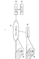
- FIG. 1 is an explanatory diagram showing a configuration example of the wireless communication system 1. As illustrated in FIG. 1, the wireless communication system 1 includes an operator domain 10, an MTC terminal 20, an MTC gateway 30, and an MTC server 40.
- the operator domain 10 is an MME (Mobility Management Entity) for setting, releasing and handover control of a data communication session, an S-GW (Serving Gateway) for routing and transferring user data, and an eNodeB, a relay node Or a base station such as Home eNodeB which is a small home base station.
- MME Mobility Management Entity
- S-GW Serving Gateway
- eNodeB a relay node Or a base station such as Home eNodeB which is a small home base station.
- the MTC server 40 is a node that manages each MTC terminal 20 and controls each MTC terminal 20 to collect, for example, information.
- FIG. 1 shows an example in which the MTC server 40 is arranged outside the operator domain 10, the MTC server 40 may be arranged inside the operator domain 10.
- the MTC server 40 operates according to a command issued from the MTC user 42, for example.
- the MTC terminal 20 is a radio terminal specialized for MTC, which is discussed in 3GPP and is communication that is not directly used by humans between machines.
- the MTC terminal 20 communicates with the operator domain 10 according to the application. Further, the MTC terminal 20 performs bidirectional communication with the MTC server 40 via the operator domain 10.
- the MTC terminal 20 collects human electrocardiogram information and transmits the electrocardiogram information to the server using an uplink when a certain trigger condition is satisfied.
- the vending machine functions as the MTC terminal 20 and the MTC server 40 reports sales to the managed vending machine at regular intervals (for example, 30 days).
- Such an MTC terminal 20 generally has the following characteristics as an example. However, each MTC terminal 20 does not have to have all the following characteristics, and which characteristics are dependent on an application. ⁇ There is almost no movement (Low Mobility) ⁇ Small-capacity data transfer (Online Small Data Transmission) ⁇ Ultra Low Power Consumption ⁇ Grouping and handling each MTC (Group based MTC Features)
- the MTC terminal 20 is an example of a user terminal (UE: User Equipment), and the embodiment of the present invention is also applicable to a non-MTC terminal such as a mobile phone or a PC (Personal Computer).
- UE User Equipment
- non-MTC terminal such as a mobile phone or a PC (Personal Computer).
- one or two or more MTC terminals 20 are subordinate to the MTC gateway 30 and connected to the operator domain 10 including the base station on behalf of the subordinate MTC terminals 20. It is considered that this MTC gateway 30 can be introduced from the following background. (1) Since the number of MTC terminals 20 is assumed to be enormous, management from the base station can be simplified by bundling and handling the plurality of MTC terminals 20 by the MTC gateway 30. (2) A case where the function of the MTC terminal 20 is implemented in any one of the devices is conceivable. (3) A case where the MTC terminal 20 has a communication interface different from 4G such as a wireless LAN defined in Zigbee or IEEE802.11 is conceivable.
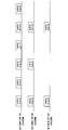
- the MTC gateway 30 described above can be realized in various forms in relation to the base station 12 and the MTC terminal 20. Hereinafter, an example of implementation of the MTC gateway 30 will be described with reference to FIGS.
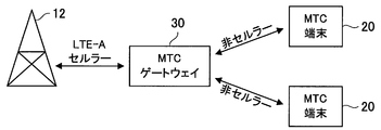
- FIG. 2 is an explanatory diagram showing a first implementation form of the MTC gateway 30.
- the MTC gateway 30 is connected to the base station 12 by LTE-A cellular, and is connected to the MTC terminal 20 by non-cellular such as Zigbee or wireless LAN.
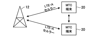
- FIG. 3 is an explanatory diagram showing a second mode of realization of the MTC gateway 30.
- the MTC gateway 30 is connected to the base station 12 by LTE-A cellular, and is also connected to the MTC terminal 20 by LTE-A cellular.
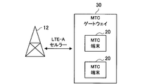
- FIG. 4 is an explanatory view showing a third mode of realization of the MTC gateway 30.
- the function of the MTC terminal 20 is implemented in the MTC gateway 30, the MTC gateway 30 is connected to the base station 12 by LTE-A cellular, and the dedicated interface in the MTC terminal 20 and the MTC gateway 30 is used. Connected.
- FIG. 5 is an explanatory diagram showing a fourth mode of realization of the MTC gateway 30.
- the MTC gateway 30 does not exist, but the MTC terminal 20 operates in a coordinated manner. For example, when one MTC terminal 20 represents another MTC terminal 20, the MTC gateway 30 virtually 30 functions are realized.
- MTC gateway 30 viewed from the base station 12
- the MTC gateway 30 is recognized as one UE from the base station 12, and the presence of the MTC terminal 20 subordinate to the MTC gateway 30 from the base station 12 is confirmed. I can't recognize it.
- the base station 12 since the base station 12 only needs to communicate with the MTC gateway 30, it is possible to reduce the load on the C-Plane by reducing signaling.
- the MTC gateway 30 in reality, when a plurality of MTC terminals 20 having different categories belong to the MTC gateway 30, it is difficult to represent the MTC gateway 30 in a single category. The category will be described later in “1-4. Category of UE and MTC terminal”.
- the MTC gateway 30 Although the MTC gateway 30 actually exists and performs communication, the MTC gateway 30 is logically transparent, and it appears to the base station 12 that only the MTC terminal 20 exists. In this case, the base station 12 can directly handle the category and attribute of each MTC terminal 20, but the signaling is not reduced.
- the MTC gateway 30 transparently relays communication between the base station 12 and the MTC terminal 20, but by performing some settings and communication on behalf of the MTC terminal 20, the base station 12 to the MTC gateway 30 can also The MTC terminal 20 is also recognized. In this case, the signaling load can be reduced because the MTC gateway 30 for a part of the settings is performed on behalf of the MTC terminal 20.
- the entity of the MTC gateway 30 does not exist, and the base station 12 directly communicates with each MTC terminal 20, but the MTC terminals 20 operate in cooperation, and one MTC terminal 20 represents another MTC terminal 20. Thus, it is recognized that the MTC gateway 30 is logically present from the base station 12.
- the MTC gateway 30 in the case 2 and the case 3 has a similar aspect to the 4G relay node currently considered, but is recognized by the eNodeB and UE (including the MTC terminal 20).
- the relay node is recognized as a relay node from the eNodeB and recognized as eNodeB from the UE, but the MTC gateway 30 is recognized as the MTC terminal 20 from the base station 12 as described above.
- the MTC terminal 20 is recognized as a base station such as Zigbee or wireless LAN.
- the MTC gateway 30 according to the present embodiment may be defined as a classification of the relay node.
- the MTC gateway 30 viewed from the MTC terminal 20
- the MTC gateway 30 and the MTC terminal 20 are connected via a wireless LAN or the like, and the MTC terminal 20 recognizes the MTC gateway 30 as an access point such as a wireless LAN.
- the MTC terminal 20 can be accommodated in the 4G communication system even if the MTC terminal 20 is a non-cellular system, but it is difficult for each MTC terminal 20 to perform the operation required by 4G. is there.
- the function of the MTC terminal 20 is implemented in the MTC gateway 30, and the MTC gateway 30 and the MTC terminal 20 are connected by a dedicated interface. In this case, it is not necessary to prepare a plurality of MTC terminals 20 individually. For example, it is conceivable that the function of the MTC terminal 20 is implemented in one apparatus such as a mobile phone.
- the entity of the MTC gateway 30 does not exist, and the base station 12 directly communicates with each MTC terminal 20, but the MTC terminals 20 operate in cooperation, and one MTC terminal 20 represents another MTC terminal 20.
- the MTC gateway 30 is logically present from the base station 12. This case has the advantage that the MTC gateway 30 is not required, but how to coordinate the MTC terminals 20 is a consideration.
- the MTC gateway 30 is connected to the MTC terminal 20 in a form conforming to a 4G line.
- the MTC gateway viewed from the above will be described focusing on the MTC gateway 30 corresponding to the case (A) or the case (B).
- Each embodiment of the present invention described below includes embodiments related to categories, embodiments related to paging, and embodiments related to random access. Therefore, prior to description of each embodiment, categories, paging, and random access will be described.
- UE categories are classified into categories 1 to 5. This category is classified according to the capability of the UE as shown below.
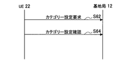
- FIG. 6 is an explanatory diagram showing a sequence for category setting. As shown in FIG. 6, the UE 22 applies for its category to the base station 12 (S62), and the base station 12 returns a confirmation signal to the UE 22 (S64). Note that the UE 22 can change the category by reattaching after detaching and then applying for the category again.
- the category of UE was demonstrated, it is possible that the MTC terminal 20 is similarly classified into a plurality of categories. Therefore, an example of the category of the MTC terminal 20 examined by the present inventor is shown below.
- the category can be determined according to the capability (characteristic) of each feature such as Low Mobility and Power Consumption that the MTC terminal 20 has. Note that the above-described category classification is merely an example, and there are a wide variety of features of the MTC terminal 20, and thus it is conceivable that more categories are prepared.
- the base station 12 is considered to control communication with each MTC terminal 20 according to the category of each MTC terminal 20. For example, the base station 12 may make a measurement request to the MTC terminal 20 whose Mobility is “High Mobility” more frequently than the MTC terminal 20 whose “Low Mobility” is.
- the UE may transition to a sleep mode in order to save power consumption.
- the UE operating in the sleep mode observes a paging channel transmitted from the base station 12 in a DRX (Discontinues Reception) cycle, and when there is no message addressed to itself, returns to a low power consumption state. If there is, perform the operation according to the message.
- the paging channel includes an incoming call for notifying that the data addressed to the UE exists in the base station 12, and a message notifying that the system information (for example, the use frequency) of the base station 12 has been updated. It is. It is considered that such a sleep mode function is also implemented in the MTC terminal 20.
- Random access The UE establishes a connection with the base station 12 by performing a procedure called random access with the base station 12.
- a timing advance value for adjusting the uplink transmission timing by the UE is acquired.
- the distance between each UE and the base station 12 is different, by performing adjustment using the timing advance value so that the data transmitted from each UE reaches the base station 12 at the same time, a plurality of UEs in the uplink can have resources. Multiple blocks can be multiplexed.
- contention type is used, but a contention free type may be used for more reliable random access.
- the contention-free type is used when connecting to a new base station 12 after handover.
- the contention-free type uses some of the 64 sequences prepared, the contention-free type cannot always be used.
- FIG. 7 is a sequence diagram showing the contention type random access procedure described above.
- the UE 22 transmits a random access preamble to the base station 12 (Step 1). Since 64 sequences prepared as random access preambles are orthogonal, even if different sequences are transmitted as random access preambles with the same resource (same time and same frequency), the base station 12 separates each random access preamble. Is possible. However, when random access preambles of the same sequence are transmitted using the same resource, it is difficult for the base station 12 to detect each random access preamble due to a collision.
- the base station 12 determines the distance of the UE 22 from the reception timing of the random access preamble, and calculates a timing advance value for the UE 22 to adjust the transmission timing.
- the base station 12 transmits a random access response to the UE 22 (Step 2).
- This random access response includes the above-described timing advance value and uplink scheduling information. Note that this step is not performed when there is no free resource for uplink scheduling.
- the UE 22 transmits an L2 / L3 message in the resource indicated by the scheduling information received in Step 2 as a connection request (Step 3).
- a plurality of UEs 22 may transmit the same random access preamble, and the base station 12 may successfully receive at least one random access preamble.
- a plurality of UEs 22 recognize the random access response transmitted from the base station 12 at Step 2 as being addressed to themselves, and the plurality of UEs 22 transmit L2 / L3 messages in the same resource. For this reason, the base station 12 cannot receive any of the L2 / L3 messages transmitted from the plurality of UEs 22 or can receive any of them.
- the base station 12 When the base station 12 succeeds in receiving the L2 / L3 message transmitted from the UE 22 in Step 3, the base station 12 returns an ACK to the UE 22 (Step 4). Note that the base station 12 does not send back an ACK when there is no available ACK transmission resource. The UE 22 recognizes that the random access is successful by receiving the ACK at Step 4 in this way.
- the MTC gateway represents a transparent side or an MTC terminal. It is possible to have side surfaces.
- the details of the first embodiment of the present invention will be described below with reference to FIGS.
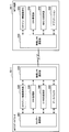
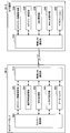
- FIG. 8 is an explanatory diagram showing configurations of the MTC terminal 20-1 and the MTC gateway 30-1 according to the first embodiment of the present invention.
- the MTC terminal 20-1 includes a wireless LAN communication unit 210, a category information holding unit 220, a DRX management unit 230, a MAC_ID holding unit 240, and an application 250.
- the MTC gateway 30-1 includes a wireless LAN communication unit 310, a category information holding unit 320, a DRX management unit 330, a C-RNTI holding unit 340, and a data buffer 350.
- the wireless LAN communication unit 210 of the MTC terminal 20-1 wirelessly communicates with the wireless LAN communication unit 310 (second communication unit) of the MTC gateway 30-1 and wireless communication standards such as IEEE802.11a, b, n, and ac. connect.
- FIG. 8 shows an example in which the MTC terminal 20-1 and the MTC gateway 30-1 are connected by a wireless LAN as an example of a non-cellular system (mobile communication system, second communication system), the MTC terminal The 20-1 and the MTC gateway 30-1 may be connected by another non-cellular system (for example, Zigbee).
- the function of the MTC terminal 20-1 may be implemented in software in the MTC gateway 30-1 as shown in FIG. 4, and in this case, the MTC terminal 20-1 has a dedicated interface with the MTC gateway 30-1. It may be connected via.
- the category information holding unit 320 of the MTC gateway 30-1 holds the category information of the MTC terminal 20-1. Since this category information may change depending on the operation of the application 250 in the MTC terminal 20-1, it is also held in the category information holding unit 220 of the MTC terminal 20-1. In this way, the MTC gateway 30-1 shares the category information with the MTC terminal 20-1, thereby realizing transparency.
- the DRX management unit 330 (intermittent reception management unit) of the MTC gateway 30-1 sets a DRX cycle (intermittent reception cycle) for the cellular communication unit 360 of the MTC gateway 30-1 to receive paging information for the MTC terminal 20-1. Maintain and manage. Similarly, the DRX management unit 230 of the MTC terminal 20-1 holds a DRX cycle for the wireless LAN communication unit 210 to receive the paging information transferred from the MTC gateway 30-1. Although details will be described with reference to FIG. 12, the DRX cycle of the MTC terminal 20-1 has an offset with respect to the DRX cycle of the MTC gateway 30-1.
- the C-RNTI holding unit 340 (identification information holding unit) of the MTC gateway 30-1 is C-RNTI that is identification information in 4G of the MTC terminal 20-1 and identification information in the wireless LAN of the MTC terminal 20-1.
- the MAC_ID is stored in association with each other.
- the MAC_ID holding unit 240 of the MTC terminal 20-1 holds the MAC_ID of the MTC terminal 20-1. Note that the MTC terminal 20-1 may hold C-RNTI in addition to MAC_ID.
- the data buffer 350 of the MTC gateway 30-1 is a buffer for temporarily storing data to be relayed between the base station 12 and the MTC terminal 20-1. For example, data from the base station 12 to the MTC terminal 20-1 and data from the MTC terminal 20-1 to the base station 12 are temporarily stored in the data buffer 350.
- the cellular communication unit 360 (first communication unit) of the MTC gateway 30-1 communicates with the base station 12 according to 4G (first communication method).
- the MTC terminal 20-1 holds the category information, the MAC_ID corresponding to the C-RNTI, and the DRX cycle, and the other 4G processing is performed on the MTC gateway 20-1 side. To do.
- the random access, data communication, and DRX operations according to the present embodiment will be described in detail.
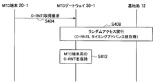
- FIG. 9 is a sequence diagram showing a random access procedure for each MTC terminal 20-1. As shown in FIG. 9, when the MTC gateway 30-1 receives a C-RNTI acquisition request from the MTC terminal 20-1 (S404), it performs random access with the base station 12 (S408).
- the MTC gateway 30-1 uses the acquired C-RNTI for the MTC terminal 20-1 as the C-RNTI. It hold
- the MTC gateway 30-1 repeats the processing shown in FIG. 9 by the number of subordinate MTC terminals 20-1. Note that the MTC gateway 30-1 may notify the acquired C-RNTI to the MTC terminal 20-1.
- FIG. 10 is an explanatory diagram showing communication related to the MTC terminal 20-1.
- the base station 12 transmits data to the MTC terminal 20-1 whose C-RNTI is “xx” and MAC_ID is “yy”.
- the base station 12 sets the destination to C-RNTI: xx and transmits data A (S420).
- the MTC gateway 30-1 When the MTC gateway 30-1 successfully receives the data A, the MTC gateway 30-1 returns an ACK to the base station 12 before confirming whether the MTC terminal 20-1 has successfully received the data A ( S422). When receiving the ACK from the MTC gateway 30-1, the base station 12 transmits the next data B (S426). The MTC gateway 30-1 returns a NACK when the reception of the data A fails, and the base station 12 retransmits the data A.
- the MTC gateway 30-1 sets the destination to MAC_ID: yy and transmits the data A to the MTC terminal 20-1 (S424). If the MTC terminal 20-1 succeeds in receiving the data A, it returns an ACK to the MTC gateway 30-1 (S428).
- the MTC gateway 30-1 performs the ACK / NACK reply on behalf, and thus it is possible to satisfy the round trip time defined for the hybrid ARQ while realizing the transparency.
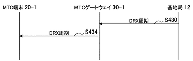
- FIG. 11 is an explanatory diagram showing a DRX cycle transmission sequence. As shown in FIG. 11, when the MTC gateway 30-1 receives the DRX cycle for intermittently receiving paging for the MTC terminal 20-1 from the base station 12, the MTC gateway 30-1 holds the DRX cycle in the DRX management unit 330 ( S430).
- the DRX management unit 330 of the MTC gateway 30-1 causes the wireless LAN communication unit 310 to transmit the DRX cycle having an offset to the DRX cycle received from the base station 12 to the MTC terminal 20-1 (S434). Thereafter, the DRX management unit 230 of the MTC terminal 20-1 holds the DRX cycle received by the wireless LAN communication unit 310.
- the relationship between the DRX cycle of the MTC gateway 30-1 and the DRX cycle of the MTC terminal 20-1 will be described with reference to FIG.
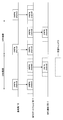
- FIG. 12 is an explanatory diagram showing intermittent reception by the MTC gateway 30-1 and the MTC terminal 20-1. As shown in FIG. 12, the MTC terminal 20-1 performs intermittent reception in conjunction with the MTC gateway 30-1. Also, the DRX cycle of the MTC terminal 20-1 has an offset with respect to the DRX cycle of the MTC gateway 30-1 in consideration of a delay from when the MTC gateway 30-1 receives the paging channel to transmission. Set to
- the MTC gateway 30-1 having a transparent aspect while satisfying the delay requirement in 4G.
- One MTC gateway may be subordinate to a plurality of MTC terminals classified into different categories.
- the feature of a category of one MTC terminal and the feature of the category of another MTC terminal may be contradictory.
- the mobility of an MTC terminal classified into category 2 shown in Table 3 is “Low Mobility”, but the mobility of an MTC terminal classified into category 5 is “High Mobility”. For this reason, if an MTC terminal classified into category 2 and an MTC terminal classified into category 5 are subordinate to the same MTC gateway, a contradiction occurs.
- the second embodiment of the present invention has been made with the above circumstances in mind, and according to the second embodiment of the present invention, it is possible to prevent the occurrence of contradictions related to category settings of MTC terminals. it can.
- the details of the second embodiment of the present invention will be described with reference to FIGS. 13 and 14.
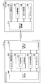
- FIG. 13 is an explanatory diagram showing configurations of the MTC terminal 20-2 and the MTC gateway 30-2 according to the second embodiment of the present invention.
- the MTC terminal 20-2 includes a wireless LAN communication unit 210, a category information holding unit 220, a category changing unit 224, a DRX management unit 230, a MAC_ID holding unit 240, and an application 250.
- the MTC gateway 30-2 includes a wireless LAN communication unit 310, a category information holding unit 320, a recommended characteristic management unit 324, a DRX management unit 330, a C-RNTI holding unit 340, and a data buffer 350.
- configurations that are different from the MTC terminal 20-1 and the MTC gateway 30-1 according to the first embodiment are mainly described. To do.
- the recommended characteristic management unit 324 (characteristic information selection unit) of the MTC gateway 30-2 selects a feature (characteristic) recommended for the subordinate MTC terminal 20, and transmits the feature from the wireless LAN communication unit 310 to the MTC terminal 20-2. Notify me.
- the recommended characteristic management unit 324 may inquire about the category of each subordinate MTC terminal 20-2 and select a recommended feature for each feature item such as “Mobility” and “Power Consumption”.
- the MTC gateway 30-2 selects a feature to be avoided and sends the feature from the wireless LAN communication unit 310 to the MTC terminal 20-2. You may be notified. For example, when the MTC terminals 20-2 in the category “Mobility” is “High Mobility” are majority, the recommended characteristic management unit 324 may select “Low Mobility” as a feature to be avoided.
- the category changing unit 224 of the MTC terminal 20-2 changes its own category as necessary based on the feature notified from the MTC gateway 30-2. For example, consider the case where the category is category 2 shown in Table 3, and “High Mobility” is notified as a recommended feature from the MTC gateway 30-2. In this case, the category changing unit 224 may change its category to a category whose Mobility is “High Mobility” such as Category 4 or 5.
- the category changing unit 224 may change its category to a category whose Mobility is “High Mobility” such as Category 4 or 5.
- the MTC terminal 20-2 may cancel the connection with the MTC gateway 30-2.
- the MTC gateway 30-2 may select a recommended category or a category to be avoided and notify the MTC terminal 20-2 of it.
- FIG. 14 is a sequence diagram showing operations of the MTC terminal 20-2 and the MTC gateway 30-2 according to the second embodiment. As shown in FIG. 14, first, when the MTC gateway 30-2 requests the category notification from the MTC terminal 20-2 (S452), the MTC terminal 20-2 responds to the request from the MTC gateway 30-2. It notifies its category to the MTC gateway 30-2 (S454).
- the MTC gateway 30-2 may transmit the category notification request to the plurality of MTC terminals 20-2 collectively by broadcasting in S452.
- the recommended characteristic management unit 324 of the MTC gateway 30-2 selects a feature recommended for the subordinate MTC terminal 20-2 based on the category of the subordinate MTC terminal 20-2 (S456). Thereafter, when the MTC gateway 30-2 receives an inquiry about a recommended feature from the MTC terminal 20-2 (S458), the MTC terminal 30-2 notifies the MTC terminal 20-2 of the feature selected in S456 (S460).
- the category changing unit 224 of the MTC terminal 20-2 adds its own feature as necessary based on the feature notified from the MTC gateway 30-2, for example, when the notified feature contradicts its own feature. Change (S462). Thereafter, the MTC terminal 20-2 holds the changed category in the category information holding unit 220, and notifies the changed category to the MTC gateway 30-2 (S464).
- the MTC gateway 30-2 notifies the category notified from the MTC terminal 20-2 to the base station 12 (S466).
- the MTC gateway 30-2 retains the category in the category information retaining unit 320 and transmits the category setting confirmation to the MTC terminal 20-2 ( S470).
- the MTC gateway 30-2 it is possible to introduce the MTC gateway 30-2 while preventing the occurrence of contradiction regarding the category setting of the MTC terminal.
- the third embodiment of the present invention has been made with the above circumstances in mind, and according to the third embodiment of the present invention, the MTC is adjusted by adjusting the DRX cycle for each MTC terminal.
- the power consumption of the gateway can be suppressed. Details of the third embodiment of the present invention will be described below with reference to FIGS.
- FIG. 15 is an explanatory diagram showing configurations of the MTC terminal 20-3 and the MTC gateway 30-3 according to the third embodiment of the present invention.
- the MTC terminal 20-3 includes a wireless LAN communication unit 210, a category information holding unit 220, a category changing unit 224, a DRX management unit 230, a MAC_ID holding unit 240, and an application 250.
- the MTC gateway 30-3 includes a wireless LAN communication unit 310, a category information holding unit 320, a recommended characteristic management unit 324, a DRX management unit 330, a C-RNTI holding unit 340, and a data buffer 350.
- configurations different from the MTC terminal 20-1 and the MTC gateway 30-1 according to the first embodiment are mainly described. To do.
- the DRX management unit 330 of the MTC gateway 30-3 includes a DRX adjustment unit 332 that adjusts the DRX cycle of a plurality of subordinate MTC terminals 20-3. Specifically, the DRX adjustment unit 332 adjusts the DRX cycle for each MTC terminal 20-3 so that the other DRX cycle of the shortest DRX cycle is an integral multiple of the shortest DRX cycle.
- each MTC terminal 20-3 has a DRX cycle of MTC terminals 20-3B and 20-3C that is an integral multiple of the DRX cycle for the shortest MTC terminal 20-3A.
- the cellular communication unit 360 of the MTC gateway 30-3 receives the paging channel in the DRX cycle for the shortest MTC terminal 20-3A
- the other MTC terminals 20-3B and 20-3C simultaneously Therefore, it is possible to receive a paging channel.
- the number of receptions of the MTC gateway 30-3 is reduced, it is possible to suppress power consumption for DRX of the MTC gateway 30-3.
- FIG. 17 is a sequence diagram showing operations of the MTC terminal 20-3 and the MTC gateway 30-3 according to the third embodiment. As shown in FIG. 17, first, when a plurality of MTC terminals 20-3A, 20-3B... Subordinate to the MTC gateway 30-3 notify the MTC gateway 30-3 of the DRX cycle (S482, S484), The DRX adjustment unit 332 of the MTC gateway 30-3 adjusts the DRX cycle for each MTC terminal 20-3 (S486).
- the DRX adjustment unit 332 of the MTC gateway 30-3 performs the DRX cycle for each MTC terminal 20-3 so that the other DRX cycle of the shortest DRX cycle is an integral multiple of the shortest DRX cycle. Adjust.
- the MTC gateway 30-3 notifies the base station 12 of the DRX cycle for each adjusted MTC terminal 20-3 (S488), and receives a DRX cycle setting confirmation from the base station 12 (S490).
- a DRX cycle setting confirmation is transmitted to each MTC terminal 20-3 (S492, S494).
- a DRX cycle may be set as described in “3GPP TS 36.300 Chapter 7.2”. This DRX cycle is broadly divided into short and long, and it is assumed that when the paging channel is not received for a predetermined period during the short operation, the DRX cycle shifts to long. This switching between short and long is performed by determination by the base station and control from the base station to the UE (MTC terminal).
- the fourth embodiment of the present invention has been made with the above circumstances in mind. According to the fourth embodiment of the present invention, the consumption of the MTC gateway is adjusted by adjusting the DRX cycle of each state. Electric power can be suppressed. The details of the fourth embodiment of the present invention will be described below with reference to FIGS.
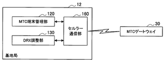
- FIG. 18 is a functional block diagram showing the configuration of the base station 12 according to the fourth embodiment.
- the base station 12 includes an MTC terminal management unit 120, a DRX adjustment unit 130, and a cellular communication unit 160.
- the MTC terminal management unit 120 manages the MTC terminals 20 subordinate to each MTC gateway 30 as a group, and holds the C-RNTI and P-RNTI (Paging Radio Network Temporary Identity) of each MTC terminal 20.
- P-RNTI is used for transmission of paging to the MTC terminal 20 whose state is RRC_IDLE
- C-RNTI or P-RNTI is used for transmission of the control signal to the MTC terminal 20 whose state is RRC_Connected. .
- the cellular communication unit 160 communicates with the MTC gateway 30 according to a cellular communication method such as 4G.
- DRX adjustment unit 130 adjusts the DRX cycle of RRC_Connected and the DRX cycle of RRC_IDLE. Specifically, since the DRX cycle of RRC_IDLE is longer than the DRX cycle of RRC_Connected, DRX adjustment unit 130 adjusts each DRX cycle so that the DRX cycle of RRC_IDLE is an integral multiple of the long DRX cycle of RRC_Connected. . Further, the DRX adjustment unit 130 adjusts each DRX cycle so that the long DRX cycle is an integral multiple of the short DRX cycle. Furthermore, the DRX adjustment unit 130 aligns the phases of the RRC_IDLE DRX cycle, the short DRX cycle, and the long DRX cycle.
- the long DRX cycle is changed even when the short DRX cycle is changed to the long DRX cycle.
- the DRX of RRC_IDLE is performed simultaneously with the DRX of RRC_Connected.
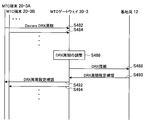
- FIG. 20 is a sequence diagram showing an operation according to the fourth embodiment. As shown in FIG. 20, first, when the MTC terminal 20 requests a DRX cycle of RRC_IDLE (S504), the MTC gateway 30 transfers the request to the base station 12 (S508).
- the DRX adjustment unit 130 of the base station 12 adjusts the DRX cycle of RRC_IDLE so as to be an integral multiple of the long DRX cycle of RRC_Connected and to be in phase with the long DRX cycle (S512). Thereafter, the setting contents of the DRX cycle are notified to the MTC terminal 20 via the MTC gateway 30 (S516, S520).
- the timing advance value is used only for the uplink between the MTC gateway and the base station. For this reason, it is considered that the timing advance value of the MTC gateway is sufficient. However, there is currently no procedure for using a timing advance value acquired by another terminal for communication with a certain terminal.
- the fifth embodiment of the present invention has been made with the above circumstances in mind, and according to the fifth embodiment of the present invention, it is possible to reduce signaling by random access and the load on the MTC gateway. Is possible. The details of the fifth embodiment of the present invention will be described below with reference to FIG.
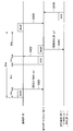
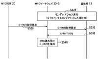
- FIG. 21 is a sequence diagram showing an operation according to the fifth embodiment. As shown in FIG. 21, first, the MTC gateway 30-5 performs random access with the base station 12 and acquires a timing advance value (S524).
- the MTC gateway 30-5 transmits a C-RNTI acquisition request for the MTC terminal 20 to the base station 12. (S532).
- the MTC gateway 30-5 When the MTC gateway 30-5 receives the C-RNTI for the MTC terminal 20 in response to a request from the base station 12 (S536), the C-RNTI for the MTC terminal 20 is sent to the C-RNTI holding unit 340. Hold (S540). The MTC gateway 30-5 may or may not notify the MTC terminal 20 of this C-RNTI.
- the MTC gateway 30-5 performs uplink communication of the MTC terminal 20 using the C-RNTI assigned in S536 and the timing advance value acquired in S524. That is, the MTC gateway 30-5 uses the common timing advance value acquired in S524 for the uplink communication of the plurality of subordinate MTC terminals 20.
- the fifth embodiment since the number of random accesses by the MTC gateway 30-5 is reduced, it is possible to reduce signaling by random access and the load on the MTC gateway 30-5.
- each step in the processing of the MTC terminal 20 or the MTC gateway 30 in this specification does not necessarily have to be processed in time series in the order described as a sequence diagram.
- each step in the processing of the MTC terminal 20 or the MTC gateway 30 may be processed in an order different from the order described as the sequence diagram or may be processed in parallel.
- the hardware such as the CPU, ROM, and RAM incorporated in the MTC terminal 20, MTC gateway 30, and base station 12 exhibits the same functions as the configurations of the MTC terminal 20, MTC gateway 30, and base station 12 described above. It is also possible to create a computer program for this purpose. A storage medium storing the computer program is also provided.
Landscapes
- Engineering & Computer Science (AREA)
- Computer Networks & Wireless Communication (AREA)
- Signal Processing (AREA)
- Mobile Radio Communication Systems (AREA)
Abstract
[Problème] Fournir un dispositif passerelle et un procédé de communication. [Solution] Le dispositif passerelle comprend: une première unité de communication qui communique avec une station de base par l'intermédiaire d'un premier procédé de communication; une seconde unité de communication qui communique avec le dispositif de communication par l'intermédiaire d'un second procédé de communication; une unité de conservation d'informations d'identité qui conserve une relation correspondante entre les secondes informations d'identité dans un second procédé de communication et les premières informations d'identité dans le premier procédé de communication du dispositif de communication; et une unité de conservation d'informations de catégorie qui est destinée à partager les informations de catégorie indiquant les propriétés du dispositif de communication avec le dispositif de communication. La première unité de communication communique avec la station de base au sujet du dispositif de communication en fonction des informations de catégorie utilisant les premières informations d'identité du dispositif de communication.
Priority Applications (3)
| Application Number | Priority Date | Filing Date | Title |
|---|---|---|---|
| EP11846403.1A EP2651180B1 (fr) | 2010-12-06 | 2011-08-17 | Dispositif passerelle et procédé de communication |
| US13/878,279 US9693389B2 (en) | 2010-12-06 | 2011-08-17 | Gateway apparatus and communication method for connecting a machine type communications terminal to a base station |
| CN201180057235.9A CN103229588B (zh) | 2010-12-06 | 2011-08-17 | 网关设备和通信方法 |
Applications Claiming Priority (2)
| Application Number | Priority Date | Filing Date | Title |
|---|---|---|---|
| JP2010271867A JP5720215B2 (ja) | 2010-12-06 | 2010-12-06 | ゲートウェイ装置および通信方法 |
| JP2010-271867 | 2010-12-06 |
Publications (1)
| Publication Number | Publication Date |
|---|---|
| WO2012077384A1 true WO2012077384A1 (fr) | 2012-06-14 |
Family
ID=46206890
Family Applications (1)
| Application Number | Title | Priority Date | Filing Date |
|---|---|---|---|
| PCT/JP2011/068621 WO2012077384A1 (fr) | 2010-12-06 | 2011-08-17 | Dispositif passerelle et procédé de communication |
Country Status (6)
| Country | Link |
|---|---|
| US (1) | US9693389B2 (fr) |
| EP (1) | EP2651180B1 (fr) |
| JP (1) | JP5720215B2 (fr) |
| CN (1) | CN103229588B (fr) |
| TR (1) | TR201819271T4 (fr) |
| WO (1) | WO2012077384A1 (fr) |
Cited By (2)
| Publication number | Priority date | Publication date | Assignee | Title |
|---|---|---|---|---|
| WO2014106877A1 (fr) * | 2013-01-07 | 2014-07-10 | 日本電気株式会社 | Système de communication mobile, plateforme de services, procédé de gestion de paramètres de réseau et support lisible par ordinateur |
| JP2016119683A (ja) * | 2011-09-13 | 2016-06-30 | クゥアルコム・インコーポレイテッドQualcomm I | Lteにおける狭帯域幅動作 |
Families Citing this family (9)
| Publication number | Priority date | Publication date | Assignee | Title |
|---|---|---|---|---|
| JP2012124603A (ja) | 2010-12-06 | 2012-06-28 | Sony Corp | 通信システムおよび通信装置 |
| US20160205628A1 (en) * | 2013-08-20 | 2016-07-14 | Kyocera Corporation | Mobile communication method, radio terminal, and radio base station |
| WO2015119555A1 (fr) * | 2014-02-06 | 2015-08-13 | Telefonaktiebolaget L M Ericsson (Publ) | Procédure d'accès aléatoire |
| US11581999B2 (en) * | 2014-10-08 | 2023-02-14 | Qualcomm Incorporated | Reference signal design for wireless communications |
| CN106304129B (zh) | 2015-05-19 | 2020-02-14 | 华为技术有限公司 | 一种监听及发送下行调度数据的方法及装置 |
| US20170111942A1 (en) * | 2015-10-19 | 2017-04-20 | Hong Fu Jin Precision Industry (Shenzhen) Co., Ltd. | Machine type communication method and mtc device using same |
| US11115793B2 (en) * | 2016-08-04 | 2021-09-07 | At&T Mobility Ii Llc | LTE gateways for home and commercial sensor data |
| US11659563B2 (en) * | 2017-01-04 | 2023-05-23 | Huawei Technologies Co., Ltd. | System and method for user equipment identifier configuration |
| US11985514B2 (en) * | 2020-08-13 | 2024-05-14 | Qualcomm Incorporated | Discontinuous reception configuration in sidelink communication deployments |
Citations (3)
| Publication number | Priority date | Publication date | Assignee | Title |
|---|---|---|---|---|
| JP2001069557A (ja) * | 1999-08-30 | 2001-03-16 | Hitachi Ltd | 無線基地局、無線中継装置、無線端末及び子機間通信方法 |
| JP2007060212A (ja) | 2005-08-24 | 2007-03-08 | Sharp Corp | 無線通信システムおよびアップリンク用リピータ装置 |
| JP2008225844A (ja) * | 2007-03-13 | 2008-09-25 | Matsushita Electric Ind Co Ltd | ガス器具監視装置 |
Family Cites Families (18)
| Publication number | Priority date | Publication date | Assignee | Title |
|---|---|---|---|---|
| US6941152B2 (en) * | 2001-04-24 | 2005-09-06 | Ipr Licensing, Inc. | Wireless subscriber network registration system for configurable services |
| US7440472B2 (en) * | 2003-08-28 | 2008-10-21 | Tekelec | Methods and systems for providing wireless local area network (WLAN)—base transceiver station (BTS) gateway |
| US7415242B1 (en) * | 2003-11-10 | 2008-08-19 | Sprint Spectrum L.P. | Method and system for proximity detection for an in-building wireless repeater |
| WO2006031927A2 (fr) * | 2004-09-15 | 2006-03-23 | Tekelec | Procedes, systemes, et produits-programmes informatiques de fonctionnalite d'enregistreur de localisation des visiteurs (vlr) a passerelle sans fil wi-fi |
| WO2006043902A1 (fr) * | 2004-10-21 | 2006-04-27 | Matsushita Electric Industrial Co., Ltd. | Procede et systeme pour identifier une station mobile relais dans un reseau de communication sans fil |
| US7688724B2 (en) * | 2005-12-23 | 2010-03-30 | Avaya Inc. | Call admission control for mobility-capable telecommunications terminals |
| CN101467422A (zh) * | 2006-06-20 | 2009-06-24 | 阿尔卡特朗讯公司 | 安全通信网络用户移动性装置和方法 |
| US20080232310A1 (en) * | 2007-03-19 | 2008-09-25 | Shugong Xu | Flexible user equipment-specified discontinuous reception |
| GB2449923B (en) | 2007-06-09 | 2011-09-28 | King S College London | Inter-working of networks |
| WO2009026281A1 (fr) * | 2007-08-20 | 2009-02-26 | Research In Motion Limited | Temporisateur d'inactivité dans un système configuré à réception discontinue |
| CN101448325B (zh) * | 2007-11-27 | 2012-11-21 | 电信科学技术研究院 | 一种随机接入过程中的处理方法和基站 |
| TWI375929B (en) * | 2008-04-03 | 2012-11-01 | Univ Nat Taiwan | Automatic-routing gateway device for wireless sensor network |
| US20110164527A1 (en) * | 2008-04-04 | 2011-07-07 | Mishra Rajesh K | Enhanced wireless ad hoc communication techniques |
| TWI369099B (en) * | 2008-05-08 | 2012-07-21 | Inst Information Industry | Relay station, access point, transmission method, and tangible machine-readable medium thereof for use in a wireless mesh network |
| US8289894B2 (en) * | 2008-09-15 | 2012-10-16 | Sharp Laboratories Of America, Inc. | Systems and methods for inter relay interference coordination |
| US8315182B2 (en) * | 2008-11-03 | 2012-11-20 | Htc Corporation | Method and related communication device for parameter reconfiguration in a wireless communications system |
| CN102217352B (zh) * | 2008-11-18 | 2016-04-20 | 诺基亚技术有限公司 | 在通信系统中进行中继 |
| JP2012124603A (ja) | 2010-12-06 | 2012-06-28 | Sony Corp | 通信システムおよび通信装置 |
-
2010
- 2010-12-06 JP JP2010271867A patent/JP5720215B2/ja not_active Expired - Fee Related
-
2011
- 2011-08-17 WO PCT/JP2011/068621 patent/WO2012077384A1/fr active Application Filing
- 2011-08-17 EP EP11846403.1A patent/EP2651180B1/fr not_active Not-in-force
- 2011-08-17 TR TR2018/19271T patent/TR201819271T4/tr unknown
- 2011-08-17 CN CN201180057235.9A patent/CN103229588B/zh not_active Expired - Fee Related
- 2011-08-17 US US13/878,279 patent/US9693389B2/en active Active
Patent Citations (3)
| Publication number | Priority date | Publication date | Assignee | Title |
|---|---|---|---|---|
| JP2001069557A (ja) * | 1999-08-30 | 2001-03-16 | Hitachi Ltd | 無線基地局、無線中継装置、無線端末及び子機間通信方法 |
| JP2007060212A (ja) | 2005-08-24 | 2007-03-08 | Sharp Corp | 無線通信システムおよびアップリンク用リピータ装置 |
| JP2008225844A (ja) * | 2007-03-13 | 2008-09-25 | Matsushita Electric Ind Co Ltd | ガス器具監視装置 |
Non-Patent Citations (3)
| Title |
|---|
| "3rd Generation Partnership Project; Technical Specification Group Services and System Aspects; Service requirements for Machine-Type Communications (MTC); Stage 1(Release 10)", 3GPP TS 22.368 V10.2.0, September 2010 (2010-09-01), XP050442387 * |
| "3rd Generation Partnership Project; Technical Specification Group Services and System Aspects; Study on Enhancements for MTC; (Release 11)", 3GPP TSG-SA WG1 MEETING #52, S1-103220, 8 November 2010 (2010-11-08) - 12 November 2010 (2010-11-12), XP050514234 * |
| See also references of EP2651180A4 |
Cited By (4)
| Publication number | Priority date | Publication date | Assignee | Title |
|---|---|---|---|---|
| JP2016119683A (ja) * | 2011-09-13 | 2016-06-30 | クゥアルコム・インコーポレイテッドQualcomm I | Lteにおける狭帯域幅動作 |
| WO2014106877A1 (fr) * | 2013-01-07 | 2014-07-10 | 日本電気株式会社 | Système de communication mobile, plateforme de services, procédé de gestion de paramètres de réseau et support lisible par ordinateur |
| CN104919825A (zh) * | 2013-01-07 | 2015-09-16 | 日本电气株式会社 | 移动通信系统、服务平台、网络参数控制方法和计算机可读介质 |
| JPWO2014106877A1 (ja) * | 2013-01-07 | 2017-01-19 | 日本電気株式会社 | 移動通信システム、サービスプラットフォーム、ネットワークパラメータ制御方法及びプログラム |
Also Published As
| Publication number | Publication date |
|---|---|
| TR201819271T4 (tr) | 2019-01-21 |
| US20130201920A1 (en) | 2013-08-08 |
| CN103229588A (zh) | 2013-07-31 |
| CN103229588B (zh) | 2016-09-07 |
| JP2012124602A (ja) | 2012-06-28 |
| EP2651180B1 (fr) | 2018-10-10 |
| US9693389B2 (en) | 2017-06-27 |
| EP2651180A1 (fr) | 2013-10-16 |
| EP2651180A4 (fr) | 2015-12-30 |
| JP5720215B2 (ja) | 2015-05-20 |
Similar Documents
| Publication | Publication Date | Title |
|---|---|---|
| WO2012077385A1 (fr) | Système de communication et dispositif de communication | |
| JP5720215B2 (ja) | ゲートウェイ装置および通信方法 | |
| US11190989B2 (en) | Mobility management for inter-gNB (next generation node-b) handover in new radio (NR) systems | |
| US20200245318A1 (en) | Communication system | |
| KR102454342B1 (ko) | 무선 액세스 네트워크 업데이트 절차에 참여하는 사용자 장비 및 기지국 | |
| KR102359746B1 (ko) | 차세대 이동통신 시스템에서 인액티브 모드 단말이 데이터를 전송하는 방법 및 장치 | |
| US9357459B2 (en) | Method and apparatus for cross link establishment | |
| KR20170022889A (ko) | 무선 통신 시스템에서 페이징을 송수신하는 방법 및 장치 | |
| US11838790B2 (en) | Method and apparatus for configuring PDCP device and SDAP device in next-generation mobile communication system | |
| US20150327204A1 (en) | Synchronization method and apparatus for d2d communication | |
| WO2012163302A1 (fr) | Procédé, terminal et système pour accéder à un réseau | |
| US11096236B2 (en) | Base station, entity and method | |
| CN107277835B (zh) | 一种处理用户平面演进式分组系统最佳化程序的通信装置 | |
| CN109155951B (zh) | 传输方法、基站和终端 | |
| KR20180050071A (ko) | 무선 통신 시스템에서 리모트 단말 및 릴레이 단말의 동작 방법 및 장치 | |
| CN114731737A (zh) | 通信系统、通信终端及基站 | |
| KR20180047652A (ko) | 무선 통신 시스템에서 서비스 제공 방법 및 장치 | |
| WO2013122587A1 (fr) | Mécanisme de coopération permettant de baisser la consommation électrique pendant la veille | |
| KR20170125292A (ko) | 연결 상태 변경 방법 및 그 장치 | |
| JP6298745B2 (ja) | ユーザ装置及び基地局 |
Legal Events
| Date | Code | Title | Description |
|---|---|---|---|
| 121 | Ep: the epo has been informed by wipo that ep was designated in this application |
Ref document number: 11846403 Country of ref document: EP Kind code of ref document: A1 |
|
| WWE | Wipo information: entry into national phase |
Ref document number: 13878279 Country of ref document: US |
|
| WWE | Wipo information: entry into national phase |
Ref document number: 2011846403 Country of ref document: EP |
|
| NENP | Non-entry into the national phase |
Ref country code: DE |