WO2012076615A2 - Method for the self-monitoring of a ceramic pressure measuring cell of a capacitive pressure sensor and an evaluation circuit for carrying out the method - Google Patents
Method for the self-monitoring of a ceramic pressure measuring cell of a capacitive pressure sensor and an evaluation circuit for carrying out the method Download PDFInfo
- Publication number
- WO2012076615A2 WO2012076615A2 PCT/EP2011/072119 EP2011072119W WO2012076615A2 WO 2012076615 A2 WO2012076615 A2 WO 2012076615A2 EP 2011072119 W EP2011072119 W EP 2011072119W WO 2012076615 A2 WO2012076615 A2 WO 2012076615A2
- Authority
- WO
- WIPO (PCT)
- Prior art keywords
- pressure
- capacitor
- measuring
- value
- measuring cell
- Prior art date
Links
Images


Classifications
-
- G—PHYSICS
- G01—MEASURING; TESTING
- G01L—MEASURING FORCE, STRESS, TORQUE, WORK, MECHANICAL POWER, MECHANICAL EFFICIENCY, OR FLUID PRESSURE
- G01L25/00—Testing or calibrating of apparatus for measuring force, torque, work, mechanical power, or mechanical efficiency
-
- G—PHYSICS
- G01—MEASURING; TESTING
- G01L—MEASURING FORCE, STRESS, TORQUE, WORK, MECHANICAL POWER, MECHANICAL EFFICIENCY, OR FLUID PRESSURE
- G01L9/00—Measuring steady of quasi-steady pressure of fluid or fluent solid material by electric or magnetic pressure-sensitive elements; Transmitting or indicating the displacement of mechanical pressure-sensitive elements, used to measure the steady or quasi-steady pressure of a fluid or fluent solid material, by electric or magnetic means
- G01L9/0026—Transmitting or indicating the displacement of flexible, deformable tubes by electric, electromechanical, magnetic or electromagnetic means
- G01L9/003—Transmitting or indicating the displacement of flexible, deformable tubes by electric, electromechanical, magnetic or electromagnetic means using variations in capacitance
-
- G—PHYSICS
- G01—MEASURING; TESTING
- G01L—MEASURING FORCE, STRESS, TORQUE, WORK, MECHANICAL POWER, MECHANICAL EFFICIENCY, OR FLUID PRESSURE
- G01L27/00—Testing or calibrating of apparatus for measuring fluid pressure
- G01L27/007—Malfunction diagnosis, i.e. diagnosing a sensor defect
-
- G—PHYSICS
- G01—MEASURING; TESTING
- G01L—MEASURING FORCE, STRESS, TORQUE, WORK, MECHANICAL POWER, MECHANICAL EFFICIENCY, OR FLUID PRESSURE
- G01L9/00—Measuring steady of quasi-steady pressure of fluid or fluent solid material by electric or magnetic pressure-sensitive elements; Transmitting or indicating the displacement of mechanical pressure-sensitive elements, used to measure the steady or quasi-steady pressure of a fluid or fluent solid material, by electric or magnetic means
- G01L9/12—Measuring steady of quasi-steady pressure of fluid or fluent solid material by electric or magnetic pressure-sensitive elements; Transmitting or indicating the displacement of mechanical pressure-sensitive elements, used to measure the steady or quasi-steady pressure of a fluid or fluent solid material, by electric or magnetic means by making use of variations in capacitance, i.e. electric circuits therefor
Definitions
- the invention relates to a method for self-monitoring of a ceramic pressure measuring cell of a capacitive pressure sensor and to an evaluation circuit for carrying out the method according to the preamble of claims 1 and 2 or claim 9.
- Capacitive pressure sensors are used in many industries for pressure measurement. They often have a ceramic pressure measuring cell, as a transducer for the process pressure, and an evaluation for signal processing.
- Capacitive pressure measuring cells consist of a ceramic base body and a membrane, wherein a glass solder ring is arranged between the base body and the membrane. The resulting cavity between the body and membrane allows the longitudinal mobility of the membrane due to a pressure influence. On the underside of the membrane and on the opposite upper side of the main body electrodes are provided, which together form a measuring capacitor. Pressure causes a deformation of the membrane, which results in a capacitance change of the measuring capacitor.
- the capacitance change is detected and converted into a pressure measurement value.
- these pressure sensors are used to monitor or control processes. They are therefore often connected to higher-level control units (PLC).
- PLC higher-level control units
- a capacitive pressure sensor is known in which the pressure measurement value is determined from the quotient of two capacitance values, a measurement capacitor and a reference capacitor.
- a pressure measuring cell is not specifically described in this specification, the circuit shown and the method described is suitable for capacitive pressure measuring cells.
- C M denotes the capacitance of the measuring capacitor
- C R the capacitance of the reference capacitor
- p the process pressure to be determined. It is also conceivable to exchange C M and C R in the quotient. However, the given example with C M in the denominator represents the most common form in favor of the self-linearization. Therefore, this embodiment is based on this embodiment, unless stated otherwise.
- the reliability of capacitive pressure sensors is becoming increasingly important.
- the problem with capacitive pressure sensors, which operate according to the quotient method is that a medium inlet - caused by membrane breakage or made possible by a venting - due to the quotient formation could not be detected, because in both the numerator and the denominator, the dielectric constant ⁇ r changes accordingly ,
- the problem is made more difficult if the ⁇ r of the incoming medium differs only slightly from ⁇ r of air. This is especially the case when the medium to be measured is oil.
- the ⁇ r of oil is typically between 2 and 4 while the ⁇ r of air is 1.
- the object of the present invention is to provide a method for monitoring the operation of a pressure measuring cell of a capacitive pressure sensor and a corresponding evaluation circuit, which do not have the disadvantages mentioned above, in particular allow a safe and reliable detection of media entry, such as through a possible venting channel or membrane breakage ,
- the method for self-monitoring of a pressure measuring cell of a capacitive pressure sensor in a first alternative is characterized in that with an additional capacitor, which is arranged outside the pressure measuring cell, a control pressure measured value is obtained and is closed by comparing the actual pressure measured value with the control pressure measured value on the functioning of the pressure measuring cell.
- the essential idea of the invention is, in the case of a capacitive pressure sensor with a ceramic pressure measuring cell with the aid of an additional capacitor C Z , whose capacity is independent of the diaphragm pressure, to determine a control pressure measured value which is compared with the actual pressure measured value.
- the condition for this is that both the capacitance of the measuring capacitor and a proportion of that of the reference capacitor due to a pressure influence is variable, while the capacity of the additional capacitor remains constant, since it is independent of the applied pressure.
- the comparison of the actual pressure measurement value with the control pressure measured value advantageously takes place via a subtraction of the two measured values.
- a quotient formation is also conceivable, however, for example, at zero pressure, the computational risk of a division by zero could arise.
- the pressure measured value and / or the control pressure measured value are obtained by means of a quotient method.
- the denominator required for the second quotient for the control measured value is advantageously the same as that of the first for the actual pressure value.
- the dielectric would have to be determined, for example via a climate sensor, in order to compensate for fluctuations in the capacitances due to changes in the dielectric conductivity or permittivity.
- the quotient method this would not be necessary because the dielectric constant changes to the same extent both in the numerator and in the denominator.
- the calibration of the capacitive pressure sensor is carried out so that the control pressure measured value and the actual pressure measurement have the same functional dependence on the process pressure, so by simply comparing both measured values, z. B. using a differential amplifier, a diagnostic value can be determined.
- the object shown can also be solved digitally by the method for self-monitoring of a pressure measuring cell of a capacitive pressure sensor according to the invention characterized in that a processing unit consisting of at least one converter unit and a microcontroller, is provided, in which the capacitance values of the measuring capacitor and the reference capacitor are detected from both capacitance values, the pressure measured value is detected and in which a further capacitance value is detected, which corresponds to an additional capacitor and from which a control pressure measured value is obtained, wherein by comparing the pressure measured value with the Control pressure reading is closed on the functioning of the pressure cell.
- a processing unit consisting of at least one converter unit and a microcontroller
- the capacitance values of measuring capacitor and reference capacitor are detected by a converter unit and forwarded to a microcontroller, where both the quotient calculation and the comparison of pressure measurement value and control pressure measurement value take place.
- the additional capacitor can be present either as a component or component whose capacitance value is also detected by the converter unit and passed on to the microcontroller, or in the form of a stored in the processing unit, in particular in the microcontroller capacitance value.
- the invention relates to an evaluation circuit for a capacitive sensor, comprising a measuring capacitor and a reference capacitor, wherein the reference capacitor is provided in a differentiating branch and the measuring capacitor in an integrating branch, which are both connected in parallel and supplied with a voltage signal. wherein the output of the integrating branch is supplied to the differentiating branch, at whose output a first pressure-dependent output signal is applied.
- a control measuring branch is connected in parallel with the differentiating branch with an additional capacitor, and the output signal of the integrating branch is additionally supplied to the control measuring branch, at whose output a second pressure-dependent output signal is present. Both output signals are then fed to a comparator unit, at whose output a diagnostic signal is output.
- the two pressure-dependent output signals of differential and control measuring branch can be supplied both directly to the comparator unit and indirectly, for example via a respective sample-and-hold circuit, which converts the square-wave voltage to DC voltage.
- FIG. 1 is a block diagram of a capacitive pressure sensor
- FIG. 2 is a schematic sectional view of a capacitive pressure measuring cell
- FIG. 3 shows an evaluation circuit for a capacitive pressure measuring cell according to FIG. 2,
- FIG. 4 shows an evaluation circuit according to the invention for a capacitive pressure measuring cell according to FIG. 2,
- FIG. 5 shows an evaluation circuit according to the invention for a capacitive pressure measuring cell according to FIG. 2 without sample-and-hold circuits
- FIG. 6 shows a diagram which simplifies the behavior of the three capacitance values C M , C R , C Z over the pressure
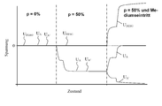
- FIG. 7 shows a diagram which simplifies the behavior of the diagnostic voltage U DIAG in the three states of no pressure, pressure influence and cell defect due to medium entry, and
- FIG. 8 shows an alternative to the figures 3-5 embodiment of the method according to the invention.
- the pressure sensor 1 shows a block diagram of a typical capacitive pressure sensor used to measure a process pressure p (eg of oil, milk, water, etc.).
- the pressure sensor 1 consists essentially of a pressure measuring cell 10 and an evaluation 20.
- the evaluation 20 has an analog evaluation circuit 30 and a microcontroller ⁇ C, in which the analog output signal of the evaluation circuit 20 is digitized and further processed.
- the microcontroller ⁇ C provides the evaluation result as a digital or analog output signal z.
- the pressure sensor 1 is connected to a power supply line (12 - 36 V).
- FIG. 2 shows a typical capacitive pressure measuring cell 10, as it is widely used in capacitive pressure sensors, in a schematic representation.
- the pressure measuring cell 10 essentially consists of a base body 12 and a membrane 14, which are connected to each other via a glass solder ring 16.
- the main body 12 and the diaphragm 14 delimit a cavity 19, which is connected to the rear side of the pressure measuring cell 10 via a venting channel 18, preferably only at low pressure ranges of up to 50 bar.
- a plurality of electrodes are provided which form a reference capacitor C R and a measuring capacitor C M.
- the measuring capacitor C M is formed by the membrane electrode ME and the center electrode M, the reference capacitor C R through the ring electrode R and the membrane electrode ME.
- the process pressure p acts on the membrane 14, which bends more or less in accordance with the pressurization, wherein substantially the distance of the membrane electrode ME to the center electrode M changes. This leads to a corresponding change in capacitance of the measuring capacitor C M.
- the influence on the reference capacitor C R is lower, since the distance between the ring electrode R and the membrane electrode ME changes less than the distance between the membrane electrode ME to the center electrode M.
- C M therefore designates both the measuring capacitor itself, as well as its capacity.
- FIG. 3 shows a known evaluation circuit 30 for the pressure measuring cell 10 in more detail.
- the measuring capacitor C M is arranged together with a resistor R 1 in an integrating branch IZ and the reference capacitor C R together with a resistor R 2 in a differentiating branch DZ.
- a square wave voltage U E0 At the input of Integrierzweigs IZ is a square wave voltage U E0 , which preferably varies symmetrically by 0 volts.
- the input voltage U E0 is converted via the resistor R 1 and the measuring capacitor C M by means of an operational amplifier OP1, which acts as an integrator, into a linearly rising or falling voltage signal (depending on the polarity of the input voltage) output at the output COM of the integrating branch IZ becomes.
- the measuring point P1 is virtually grounded by the operational amplifier OP1.
- the output COM is connected to a threshold comparator SG, which drives a square-wave generator RG. As soon as the voltage signal at the output COM exceeds or falls below a threshold value, the comparator SG changes its output signal, whereupon the square-wave generator inverts its output voltage in each case.
- the differentiating branch DZ is further comprised of an operational amplifier OP2, a voltage divider with the two resistors R 5 and R 6, and a feedback resistor R. 7
- the output of the operational amplifier OP2 is connected to a sample-and-hold circuit S & H.
- the measurement voltage U Mess At the output of the sample-and-hold circuit S & H is the measurement voltage U Mess , which is proportional to the process pressure p, which acts on the pressure measuring cell 10 is.
- the operational amplifier OP1 ensures that the connection point P1 between the resistor R 1 and the measuring capacitor C M is virtually kept at ground. As a result, a constant current I 1 flows through the resistor R 1 , which charges the measuring capacitor C M until the square-wave voltage U E0 changes its sign
- the positive and negative pulse height A + or A- of the rectangular pulse is determined via a sample and hold circuit S & H and the amount A is output as measurement voltage U Mess at the output of the operational amplifier OP3 and forwarded to the microcontroller mC (not shown). It could also be output directly as an analog value.
- the pulse height of the input voltage U E0 which is applied to the output of the square wave generator RG, is adjusted as a function of the measuring voltage U Mess in order to achieve a better linearity.
- a voltage divider consisting of the resistors R 20 and R 10 is provided. This voltage divider is connected to a reference voltage VREF and advantageously adjustable.
- the evaluation circuit 30a according to the invention is shown. However, this circuit corresponds to the circuit of FIG. 3, however, with an additional control measuring branch KMZ and a comparator unit VE.
- the control measuring branch KMZ comprises a resistor R 2 'and an additional capacitor C Z , which are arranged parallel to the resistor R 1 and the measuring capacitor C M.
- an operational amplifier OP2' To the measuring point P2 'is connected an operational amplifier OP2', which operates as a differentiator as the operational amplifier OP2.
- U D At the output of the operational amplifier OP2 'is a square wave voltage U D , which is proportional to the expression C Z / C M - 1.
- This square-wave voltage is also rectified with a sample and hold circuit S & H '(voltage U A' at point A ') and then compared with the measuring voltage U Mess in a comparator unit VE with the aid of a differential amplifier OP4.
- the functional profile of the square-wave voltage U D - or the voltage U A ' at A' - can be dimensioned in dependence on the process pressure p in accordance with the course of the measuring voltage U Mess .
- the diagnostic voltage U DIAG At the output of the differential amplifier OP4 is the diagnostic voltage U DIAG .
- the diagnostic voltage U DIAG essentially follows the expression
- correction factors k1 to k4 are advantageously realized by tunable resistor networks; their placements in the illustrated formula are intended to be exemplary only and, of course, may be changed depending on the intended direction of proportionality.
- a medium entry or a diaphragm rupture only has an effect on the capacitance values of the two capacitors C R and C M or only on the capacitance value of one of these two capacitors, but not on C Z , so that in this case the voltage U DIAG noticeably decreases from zero differs.
- This deviation can be registered by a microcontroller (not shown) and a corresponding reaction initiated. This can, for. B. exist in an alarm message, which is forwarded to the PLC or an on-site signaling.
- Fig. 5 shows a somewhat modified circuit 30b which operates without a sample and hold element.
- the advantage over the embodiment in Fig. 4 is that the circuit complexity is reduced and thus the manufacturing cost can be reduced.
- the rectangular diagnosis signal makes the interpration more difficult.
- the illustrated resistors are only symbolically meant in FIG. 5 and may each include a resistor network.
- the measuring voltage U R is a square-wave voltage as in the previously described embodiments. Therefore, the diagnostic signal U DIAG is output in a rectangular manner in this case.
- Both circuits 30a, 30b are suitable for both analog and digital further processing with a microcontroller.
- the pressure measuring cell 10 of the capacitive pressure sensor 1 has a measuring capacitor C M and a reference capacitor C R.
- As the voltage U R is advantageously obtained by a quotient method from the capacitance values of the measuring capacitor C M and the reference capacitor C R.
- an additional capacitor C Z also via a quotient method, a control pressure measured value p ', z. B. the voltage U D won. Since the additional capacitor C Z is arranged so that it remains completely unaffected by a membrane rupture of the membrane 14 or by a medium inlet into the pressure measuring cell 10, the two measured values change in each case differently.
- the calibration of the capacitive pressure sensor takes place so that the control pressure measured value p 'and the pressure measured value p have the same functional dependence on the process pressure. It goes without saying that parts of the evaluation circuit 30a can also be implemented digitally in a microcontroller. The invention makes it possible to expand an existing capacitive pressure sensor by a diagnostic function without much effort.
- the method according to the invention and the corresponding evaluation circuit are suitable not only for determining a medium entry in a membrane breakage but also for the diagnosis of cracking in the membrane 14, because in this case the flexural rigidity of the membrane 14 changes and this determined differently on the above the reference capacitor C R. Measured value p 'and the pressure measured value p determined via the measuring capacitor C M.
- FIG. 6 shows in simplified form how the three capacitance values C M , C R , C Z behave above the pressure.
- the curve of the measuring capacitor C M has the largest slope, because it is located in the middle of the diaphragm 14 of the pressure measuring cell 10 and thus the diaphragm 14 has the greatest deflection under the influence of pressure here.
- the reference capacitor C R is located at the edge of the membrane 14, where the change in distance between the two electrodes R, ME is lower. Therefore, the capacity increase per unit pressure is less than the measuring capacitor C M. It can finally be seen that the capacity of the additional capacitor C Z does not change and remains constant over the entire pressure curve. That is the essential condition of the invention.
- the arrow between C M and C R illustrates the magnitude of the actual measurement voltage U R , the arrow between C M and C Z the magnitude of the output voltage U D of the control measuring branch KMZ.
- FIG. 7 shows a diagram which shows the behavior of the diagnosis voltage U DIAG in the three states no pressure, pressure influence and cell defect due to medium entry. Simplified means that this is a schematic diagram, so that actual waveforms could be slightly different, especially in terms of amount. Also, other influences, such as resistive errors o. The like., Not considered.
- the fundamental signal course was modeled after an actual measurement.
- the signals U A and U A ' at the points A and A' are the converted by the sample-and-hold circuit to DC voltage output signals U R and U D of the differentiating branch DZ and the control measuring branch KMZ.
- the voltage U DIAG is the diagnostic voltage as the difference between the two signals U A and U A ' .
- the diagram thus clarifies the operation of the comparator unit VE.
- the last third of the diagram shows the signal curves at medium entry, again assuming a 50% pressure load. Since now the medium to be measured is located within the measuring cell, ie in the hollow body 19 delimited by the main body 12 and the membrane 14, the same pressure prevails as outside the membrane 14 and the now increased permittivity does not affect the amount of the quotient out. Consequently, the signal U A moves as a measure of the actual measurement voltage U measurement in the direction of 0 volts. A step-shaped waveform yields sch again through the sample-and-hold circuit S & H.
- the signal U A ' moves due to the still constant capacitance C Z , which is in the numerator of the quotient for calculating U A' , and due to increased permittivity unilaterally increasing capacity C M , in the denominator of the quotient for the calculation of U A ' stands, in a negative direction.
- the diagnostic voltage U DIAG as a difference between the two signals U A and U A ' now moves clearly in the positive direction. At least - and that is the decisive factor - the diagnostic voltage U DIAG is not equal to zero, which can be recognized as a measure of a cell defect and further processed.
- FIG. 8 shows an alternative embodiment of the method according to the invention to FIGS. 4 and 5.
- the pressure measuring cell 10 is identical to the previously described embodiments.
- the capacitance changes of C M and C R resulting from the pressure influence are not evaluated analogously but digitally in a processing unit 50 consisting of at least one converter unit 55 and a microcontroller 51.
- a processing unit 50 consisting of at least one converter unit 55 and a microcontroller 51.
- a converter unit 55 is provided which, for example, can be designed as an AD7745 circuit "Capacitance To Digital Converter” by Analog Devices.
- a converter unit 55 is provided for both capacitors C M and C R.
- C M and C R are then fed to a microcontroller 51, in whose processor unit 52 the quotient terms C R / C M -1 and C Z / C M -1 are calculated and compared in the previously described manner by subtraction ,
- the value for C Z either comes, as shown in FIG. 8, from a memory unit 53, which is preferably located within the microcontroller 51 and in which a capacitance value representing an additional capacitor C Z is stored, or alternatively from outside the processing unit 50 arranged, designed as a component or component capacitor whose capacitance is also detected by a converter unit 55 and digitized the microcontroller 51 is supplied.
Abstract
A capacitive pressure sensor is presented and described, comprising a ceramic pressure measuring cell, in which, with the aid of an additional capacitor, the capacitance of which is independent of the membrane pressure, a control pressure measurement value is determined preferably according to the quotient method and said control pressure measurement value is compared with the actual pressure measurement value. The capacitive pressure sensor is advantageously calibrated such that the control pressure measurement value and the actual pressure measurement value have the same functional dependence on the process pressure p, in order that a diagnosis value can be determined by simple comparison of the two measurement values, e.g. with the aid of a differential amplifier.
Description
Die Erfindung betrifft ein Verfahren zur Selbstüberwachung einer keramischen Druckmesszelle eines kapazitiven Drucksensors sowie eine Auswerteschaltung zur Durchführung des Verfahrens gemäß dem Oberbegriff des Anspruchs 1 und 2 bzw. Anspruchs 9.The invention relates to a method for self-monitoring of a ceramic pressure measuring cell of a capacitive pressure sensor and to an evaluation circuit for carrying out the method according to the preamble of claims 1 and 2 or claim 9.
Kapazitive Drucksensoren werden in vielen Industriebereichen zur Druckmessung eingesetzt. Sie weisen häufig eine keramische Druckmesszelle, als Messwandler für den Prozessdruck, und einen Auswerteelektronik zur Signalverarbeitung auf. Capacitive pressure sensors are used in many industries for pressure measurement. They often have a ceramic pressure measuring cell, as a transducer for the process pressure, and an evaluation for signal processing.
Kapazitive Druckmesszellen bestehen aus einem keramischen Grundkörper und einer Membran, wobei zwischen dem Grundkörper und der Membran ein Glaslotring angeordnet ist. Der sich dadurch ergebende Hohlraum zwischen Grundkörper und Membran ermöglicht die längsgerichtete Beweglichkeit der Membran infolge eines Druckeinflusses. An der Unterseite der Membran und an der gegenüberliegenden Oberseite des Grundkörpers sind jeweils Elektroden vorgesehen, die zusammen einen Messkondensator bilden. Durch Druckeinwirkung kommt es zu einer Verformung der Membran, was eine Kapazitätsänderung des Messkondensators zur Folge hat. Capacitive pressure measuring cells consist of a ceramic base body and a membrane, wherein a glass solder ring is arranged between the base body and the membrane. The resulting cavity between the body and membrane allows the longitudinal mobility of the membrane due to a pressure influence. On the underside of the membrane and on the opposite upper side of the main body electrodes are provided, which together form a measuring capacitor. Pressure causes a deformation of the membrane, which results in a capacitance change of the measuring capacitor.
Mit Hilfe einer Auswerteeinheit wird die Kapazitätsänderung erfasst und in einen Druckmesswert umgewandelt. In der Regel dienen diese Drucksensoren zur Überwachung oder Steuerung von Prozessen. Sie sind deshalb häufig mit übergeordneten Steuereinheiten (SPS) verbunden.With the aid of an evaluation unit, the capacitance change is detected and converted into a pressure measurement value. Typically, these pressure sensors are used to monitor or control processes. They are therefore often connected to higher-level control units (PLC).
Aus der DE 198 51 506 C1 ist ein kapazitiver Drucksensor bekannt, bei dem der Druckmesswert aus dem Quotient zweier Kapazitätswerte, eines Messkondensators und eines Referenzkondensators, ermittelt wird. In dieser Patentschrift ist eine Druckmesszelle zwar nicht speziell beschrieben, die dargestellte Schaltung und das beschriebene Verfahren ist aber für kapazitive Druckmesszellen geeignet.From DE 198 51 506 C1, a capacitive pressure sensor is known in which the pressure measurement value is determined from the quotient of two capacitance values, a measurement capacitor and a reference capacitor. Although a pressure measuring cell is not specifically described in this specification, the circuit shown and the method described is suitable for capacitive pressure measuring cells.
Aus der EP 0 569 573 B1 ist eine Schaltungsanordnung für einen kapazitiven Drucksensor bekannt, bei dem ebenfalls ein Quotientenverfahren zur Druckauswertung eingesetzt wird. From EP 0 569 573 B1, a circuit arrangement for a capacitive pressure sensor is known in which a quotient method for pressure evaluation is also used.
Quotientenverfahren gehen in der Regel von folgenden Druckabhängigkeiten aus: Quotient methods usually assume the following pressure dependencies:
wobei CM die Kapazität des Messkondensators, CR die Kapazität des Referenzkondensators und p den zu bestimmenden Prozessdruck bezeichnet. Denkbar ist auch die Möglichkeit, CM und CR im Quotienten zu vertauschen. Das angegeben Beispiel mit CM im Nenner stellt allerdings zugunsten der Eigenlinearisierung die gebräuchlichste Form dar. Im Folgenden wird daher von dieser Ausführungsform ausgegangen, sofern nicht anders angegeben.where C M denotes the capacitance of the measuring capacitor, C R the capacitance of the reference capacitor and p the process pressure to be determined. It is also conceivable to exchange C M and C R in the quotient. However, the given example with C M in the denominator represents the most common form in favor of the self-linearization. Therefore, this embodiment is based on this embodiment, unless stated otherwise.
Die Zuverlässigkeit bei kapazitiven Drucksensoren gewinnt immer mehr an Bedeutung. Problematisch bei kapazitiven Drucksensoren, die nach dem Quotientenverfahren arbeiten, ist, dass ein Mediumseintritt – verursacht durch Membranbruch oder ermöglicht durch einen eventuellen Entlüftungskanal – aufgrund der Quotientenbildung nicht erkannt werden könnte, weil sich sowohl im Zähler als auch im Nenner die Dielektrizitätszahl εr entsprechend ändert. Erschwert wird das Problem, wenn sich das εr des eintretenden Mediums vom εr von Luft nur gering unterscheidet. Dies ist insbesondere der Fall, wenn das zu messende Medium Öl ist. Das εr von Öl liegt typischerweise zwischen 2 und 4, während das εr von Luft bei 1 liegt. The reliability of capacitive pressure sensors is becoming increasingly important. The problem with capacitive pressure sensors, which operate according to the quotient method, is that a medium inlet - caused by membrane breakage or made possible by a venting - due to the quotient formation could not be detected, because in both the numerator and the denominator, the dielectric constant ε r changes accordingly , The problem is made more difficult if the ε r of the incoming medium differs only slightly from ε r of air. This is especially the case when the medium to be measured is oil. The ε r of oil is typically between 2 and 4 while the ε r of air is 1.
Aufgabe der vorliegenden Erfindung ist es, ein Verfahren zur Funktionsüberwachung einer Druckmesszelle eines kapazitiven Drucksensors und eine entsprechende Auswerteschaltung anzugeben, die die oben genannten Nachteile nicht aufweisen, die insbesondere eine sichere und zuverlässige Erkennung eines Mediumseintritts, etwa durch einen eventuellen Entlüftungskanal oder bei Membranbruch, erlauben.The object of the present invention is to provide a method for monitoring the operation of a pressure measuring cell of a capacitive pressure sensor and a corresponding evaluation circuit, which do not have the disadvantages mentioned above, in particular allow a safe and reliable detection of media entry, such as through a possible venting channel or membrane breakage ,
Gelöst wird diese Aufgabe durch die in Anspruch 1 und 2 bzw. Anspruch 6 angegebenen Merkmale. Vorteilhafte Weiterentwicklungen der Erfindung sind in den jeweiligen Unteransprüchen angegeben. This object is achieved by the features specified in claim 1 and 2 or claim 6. Advantageous further developments of the invention are specified in the respective subclaims.
Erfindungsgemäß ist das Verfahren zur Selbstüberwachung einer Druckmesszelle eines kapazitiven Drucksensors in einer ersten Alternative dadurch gekennzeichnet, dass mit einem Zusatzkondensator, der außerhalb der Druckmesszelle angeordnet ist, ein Kontrolldruckmesswert gewonnen wird und durch Vergleich des eigentlichen Druckmesswertes mit dem Kontrolldruckmesswert auf die Funktionsfähigkeit der Druckmesszelle geschlossen wird.According to the invention, the method for self-monitoring of a pressure measuring cell of a capacitive pressure sensor in a first alternative is characterized in that with an additional capacitor, which is arranged outside the pressure measuring cell, a control pressure measured value is obtained and is closed by comparing the actual pressure measured value with the control pressure measured value on the functioning of the pressure measuring cell.
Die wesentliche Idee der Erfindung besteht darin, bei einem kapazitiven Drucksensor mit einer keramischen Druckmesszelle mit Hilfe eines Zusatzkondensators CZ, dessen Kapazität unabhängig vom Membrandruck ist, einen Kontrolldruckmesswert zu ermitteln, der mit dem eigentlichen Druckmesswert verglichen wird. Bedingung hierfür ist, dass sowohl die Kapazität des Messkondensators als auch anteilig die des Referenzkondensators infolge eines Druckeinflusses veränderlich ist, während die Kapazität des Zusatzkondensators konstant bleibt, da sie unabhängig vom anliegenden Druck ist. The essential idea of the invention is, in the case of a capacitive pressure sensor with a ceramic pressure measuring cell with the aid of an additional capacitor C Z , whose capacity is independent of the diaphragm pressure, to determine a control pressure measured value which is compared with the actual pressure measured value. The condition for this is that both the capacitance of the measuring capacitor and a proportion of that of the reference capacitor due to a pressure influence is variable, while the capacity of the additional capacitor remains constant, since it is independent of the applied pressure.
Der Vergleich des eigentlichen Druckmesswertes mit dem Kontrolldruckmesswert erfolgt vorteilhafterweise über eine Differenzbildung beider Messwerte. Prinzipiell denkbar ist auch eine Quotientenbildung, jedoch könnte sich, bspw. bei Null-Druck, die rechnerische Gefahr einer Division durch Null ergeben. The comparison of the actual pressure measurement value with the control pressure measured value advantageously takes place via a subtraction of the two measured values. In principle, a quotient formation is also conceivable, however, for example, at zero pressure, the computational risk of a division by zero could arise.
In einer vorteilhaften Weiterbildung der Erfindung wird der Druckmesswert und/oder der Kontrolldruckmesswert mit Hilfe eines Quotientenverfahrens gewonnen. Der zum zweiten Quotient für den Kontrollmesswert benötigte Nenner ist vorteilhafterweise derselbe wie der vom ersten für den eigentlichen Druckwert.In an advantageous development of the invention, the pressure measured value and / or the control pressure measured value are obtained by means of a quotient method. The denominator required for the second quotient for the control measured value is advantageously the same as that of the first for the actual pressure value.
Es ist alternativ auch denkbar, Druckwert und Kontrolldruckmesswert über eine Differenzbildung zu berechnen. In diesem Fall wäre – bspw. über einen Klimasensor – das Dielektrikum zu ermitteln, um Schwankungen der Kapazitäten aufgrund von Änderungen der dielektrischen Leitfähigkeit bzw. Permittivität auszugleichen. Beim Quotientenverfahren wäre dies hingegen nicht nötig, weil sich sowohl im Zähler als auch im Nenner die Dielektrizitätszahl im gleichen Maß ändert. Alternatively, it is also conceivable to calculate pressure value and control pressure measured value by means of a subtraction. In this case, the dielectric would have to be determined, for example via a climate sensor, in order to compensate for fluctuations in the capacitances due to changes in the dielectric conductivity or permittivity. On the other hand, in the quotient method this would not be necessary because the dielectric constant changes to the same extent both in the numerator and in the denominator.
Wenn dann die beiden Quotienten CR/CM und CZ/CM miteinander verglichen werden und die Messzelle intakt ist, bewegt sich dieser Unterschied in einem definierten Bereich. Sobald die Messzelle defekt ist, z.B. ein Membranbruch, unterscheiden sich beide Quotienten derart deutlich voneinander, dass eindeutig auf einen Fehler- bzw. Störfall geschlossen werden kann. If then the two quotients C R / C M and C Z / C M are compared with each other and the measuring cell is intact, this difference moves within a defined range. As soon as the measuring cell is defective, eg a diaphragm rupture, both quotients differ so clearly from one another that clearly one can conclude on a fault or fault.
In vorteilhafter Weise erfolgt die Kalibrierung des kapazitiven Drucksensors so, dass der Kontrolldruckmesswert und der eigentliche Druckmesswert die gleiche funktionale Abhängigkeit vom Prozessdruck aufweisen, damit durch einfachen Vergleich beider Messwerte, z. B. mit Hilfe eines Differenzverstärkers, ein Diagnosewert ermittelt werden kann.Advantageously, the calibration of the capacitive pressure sensor is carried out so that the control pressure measured value and the actual pressure measurement have the same functional dependence on the process pressure, so by simply comparing both measured values, z. B. using a differential amplifier, a diagnostic value can be determined.
Neben der zuvor beschrieben analogen Ausführung lässt sich die aufgezeigte Aufgabe auch digital verarbeitet lösen, indem in einer zweiten Alternative das Verfahren zur Selbstüberwachung einer Druckmesszelle eines kapazitiven Drucksensors erfindungsgemäß dadurch gekennzeichnet ist, dass eine Verarbeitungseinheit, bestehend aus wenigstens einer Konverter-Einheit und einem Mikrocontroller, vorgesehen ist, in der die Kapazitätswerte des Messkondensators sowie des Referenzkondensators erfasst werden, aus beiden Kapazitätswerten der Druckmesswert gebildet wird und in der ein weiterer Kapazitätswert erfasst wird, der einem Zusatzkondensator entspricht und aus dem ein Kontrolldruckmesswert gewonnen wird, wobei durch Vergleich des Druckmesswertes mit dem Kontrolldruckmesswert auf die Funktionsfähigkeit der Druckmesszelle geschlossen wird. In addition to the previously described analogous embodiment, the object shown can also be solved digitally by the method for self-monitoring of a pressure measuring cell of a capacitive pressure sensor according to the invention characterized in that a processing unit consisting of at least one converter unit and a microcontroller, is provided, in which the capacitance values of the measuring capacitor and the reference capacitor are detected from both capacitance values, the pressure measured value is detected and in which a further capacitance value is detected, which corresponds to an additional capacitor and from which a control pressure measured value is obtained, wherein by comparing the pressure measured value with the Control pressure reading is closed on the functioning of the pressure cell.
Im Unterschied zur ersten Alternative des Verfahrens werden die Kapazitätswerte von Mess- und Referenzkondensator von einer Konverter-Einheit erfasst und an einen Mikrocontroller weitergegeben, wo sowohl die Quotientenberechnung als auch der Vergleich von Druckmesswert und Kontrolldruckmesswert erfolgt. Der Zusatzkondensator kann dabei entweder als Bauteil bzw. Komponente vorliegen, dessen Kapazitätswert ebenfalls von der Konverter-Einheit erfasst und an den Mikrocontroller weitergegeben wird, oder in Form eines in der Verarbeitungseinheit, insbesondere im Mikrocontroller abgespeicherten Kapazitätswerts ausgeführt sein. In contrast to the first alternative of the method, the capacitance values of measuring capacitor and reference capacitor are detected by a converter unit and forwarded to a microcontroller, where both the quotient calculation and the comparison of pressure measurement value and control pressure measurement value take place. The additional capacitor can be present either as a component or component whose capacitance value is also detected by the converter unit and passed on to the microcontroller, or in the form of a stored in the processing unit, in particular in the microcontroller capacitance value.
In einem weiteren Aspekt betrifft die Erfindung eine Auswerteschaltung für einen oben genannten kapazitiven Sensor, mit einem Messkondensator und einem Referenzkondensator, wobei der Referenzkondensator in einem Differenzierzweig und der Messkondensator in einem Integrierzweig vorgesehen ist, die beide parallel geschaltet sind und mit einem Spannungssignal beaufschlagt werden, wobei das Ausgangssignal des Integrierzweiges dem Differenzierzweig zugeführt wird, an dessen Ausgang ein erstes druckabhängiges Ausgangssignal anliegt. Erfindungsgemäß ist parallel zum Differenzierzweig ein Kontrollmesszweig mit einem Zusatzkondensator geschaltet und das Ausgangssignal des Integrierzweiges wird zusätzlich dem Kontrollmesszweig zugeführt, an dessen Ausgang ein zweites druckabhängiges Ausgangssignal anliegt. Beide Ausgangssignale werden dann einer Vergleichereinheit zugeführt, an deren Ausgang ein Diagnosesignal ausgegeben wird. In a further aspect, the invention relates to an evaluation circuit for a capacitive sensor, comprising a measuring capacitor and a reference capacitor, wherein the reference capacitor is provided in a differentiating branch and the measuring capacitor in an integrating branch, which are both connected in parallel and supplied with a voltage signal. wherein the output of the integrating branch is supplied to the differentiating branch, at whose output a first pressure-dependent output signal is applied. According to the invention, a control measuring branch is connected in parallel with the differentiating branch with an additional capacitor, and the output signal of the integrating branch is additionally supplied to the control measuring branch, at whose output a second pressure-dependent output signal is present. Both output signals are then fed to a comparator unit, at whose output a diagnostic signal is output.
Die beiden druckabhängigen Ausgangssignale von Differenzier- und Kontrollmesszweig können dabei sowohl direkt der Vergleichereinheit zugeführt werden als auch indirekt, bspw. über jeweils eine Sample-and-Hold-Schaltung, die die Rechteckspannung zu Gleichspannung umwandelt. The two pressure-dependent output signals of differential and control measuring branch can be supplied both directly to the comparator unit and indirectly, for example via a respective sample-and-hold circuit, which converts the square-wave voltage to DC voltage.
Nachfolgend wird die Erfindung im Zusammenhang mit Figuren anhand von Ausführungsbeispielen näher erläutert.The invention will be explained in more detail in connection with figures with reference to embodiments.
Es zeigen:Show it:
Figur 1 ein Blockdiagramm eines kapazitiven Drucksensors,FIG. 1 is a block diagram of a capacitive pressure sensor;
Figur 2 eine schematische Schnittdarstellung einer kapazitiven Druckmesszelle,FIG. 2 is a schematic sectional view of a capacitive pressure measuring cell;
Figur 3 eine Auswerteschaltung für eine kapazitive Druckmesszelle gemäß Figur 2,FIG. 3 shows an evaluation circuit for a capacitive pressure measuring cell according to FIG. 2,
Figur 4 eine erfindungsgemäße Auswerteschaltung für eine kapazitive Druckmesszelle gemäß Figur 2,FIG. 4 shows an evaluation circuit according to the invention for a capacitive pressure measuring cell according to FIG. 2,
Figur 5 eine erfindungsgemäße Auswerteschaltung für eine kapazitive Druckmesszelle gemäß Figur 2 ohne Sample-and-Hold-Schaltungen,FIG. 5 shows an evaluation circuit according to the invention for a capacitive pressure measuring cell according to FIG. 2 without sample-and-hold circuits,
Figur 6 ein Diagramm, das das Verhalten der drei Kapazitätswerte CM, CR, CZ über dem Druck vereinfacht darstellt,FIG. 6 shows a diagram which simplifies the behavior of the three capacitance values C M , C R , C Z over the pressure,
Figur 7 ein Diagramm, das das Verhalten der Diagnosespannung UDIAG bei den drei Zuständen kein Druck, Druckeinfluss und Zellendefekt durch Mediumseintritt vereinfacht darstellt undFIG. 7 shows a diagram which simplifies the behavior of the diagnostic voltage U DIAG in the three states of no pressure, pressure influence and cell defect due to medium entry, and
Figur 8 eine zu den Figuren 3-5 alternative Ausführungsform des erfindungsgemäßen Verfahrens.8 shows an alternative to the figures 3-5 embodiment of the method according to the invention.
In Figur 1 ist ein Blockdiagramm eines typischen kapazitiven Drucksensors dargestellt, der zur Messung eines Prozessdrucks p (z. B. von Öl, Milch, Wasser etc.) eingesetzt wird. Der Drucksensor 1 besteht im Wesentlichen aus einer Druckmesszelle 10 und einer Auswerteelektronik 20. Die Auswerteelektronik 20 weist eine analoge Auswerteschaltung 30 und einen Mikrocontroller μC auf, in dem das analoge Ausgangssignal der Auswerteschaltung 20 digitalisiert und weiterverarbeitet wird. Der Mikrocontroller μC stellt das Auswerteergebnis als digitales oder analoges Ausgangssignal z. B. einer SPS zur Verfügung. Zur Energieversorgung ist der Drucksensor 1 an eine Spannungsversorgungsleitung (12 – 36 V) angeschlossen.1 shows a block diagram of a typical capacitive pressure sensor used to measure a process pressure p (eg of oil, milk, water, etc.). The pressure sensor 1 consists essentially of a pressure measuring cell 10 and an evaluation 20. The evaluation 20 has an analog evaluation circuit 30 and a microcontroller μC, in which the analog output signal of the evaluation circuit 20 is digitized and further processed. The microcontroller μC provides the evaluation result as a digital or analog output signal z. B. a PLC available. For power supply, the pressure sensor 1 is connected to a power supply line (12 - 36 V).
Figur 2 zeigt eine typische kapazitive Druckmesszelle 10, wie sie vielfältig bei kapazitiven Drucksensoren eingesetzt wird, in schematischer Darstellung. Die Druckmesszelle 10 besteht im Wesentlichen aus einem Grundkörper 12 und einer Membran 14, die über einen Glaslotring 16 miteinander verbunden sind. Der Grundkörper 12 und die Membran 14 begrenzen einen Hohlraum 19, der – vorzugsweise nur bei niedrigen Druckbereichen bis 50 bar – über einen Entlüftungskanal 18 mit der Rückseite der Druckmesszelle 10 verbunden ist.Figure 2 shows a typical capacitive pressure measuring cell 10, as it is widely used in capacitive pressure sensors, in a schematic representation. The pressure measuring cell 10 essentially consists of a base body 12 and a membrane 14, which are connected to each other via a glass solder ring 16. The main body 12 and the diaphragm 14 delimit a cavity 19, which is connected to the rear side of the pressure measuring cell 10 via a venting channel 18, preferably only at low pressure ranges of up to 50 bar.
Sowohl auf dem Grundkörper 12 wie auch auf der Membran 14 sind mehrere Elektroden vorgesehen, die einen Referenzkondensator CR und einen Messkondensator CM bilden. Der Messkondensator CM wird durch die Membranelektrode ME und die Mittelelektrode M gebildet, der Referenzkondensator CR durch die Ringelektrode R und die Membranelektrode ME.Both on the base body 12 and on the membrane 14, a plurality of electrodes are provided which form a reference capacitor C R and a measuring capacitor C M. The measuring capacitor C M is formed by the membrane electrode ME and the center electrode M, the reference capacitor C R through the ring electrode R and the membrane electrode ME.
Der Prozessdruck p wirkt auf die Membran 14, die sich entsprechend der Druckbeaufschlagung mehr oder weniger durchbiegt, wobei sich im Wesentlichen der Abstand der Membranelektrode ME zur Mittelelektrode M ändert. Dies führt zu einer entsprechenden Kapazitätsänderung des Messkondensators CM. Der Einfluss auf den Referenzkondensator CR ist geringer, da sich der Abstand zwischen Ringelektrode R und Membranelektrode ME weniger stark verändert als der Abstand zwischen Membranelektrode ME zur Mittelelektrode M.The process pressure p acts on the membrane 14, which bends more or less in accordance with the pressurization, wherein substantially the distance of the membrane electrode ME to the center electrode M changes. This leads to a corresponding change in capacitance of the measuring capacitor C M. The influence on the reference capacitor C R is lower, since the distance between the ring electrode R and the membrane electrode ME changes less than the distance between the membrane electrode ME to the center electrode M.
Im Folgenden wird zwischen der Bezeichnung des Kondensators und seinem Kapazitätswert nicht unterschieden. CM bezeichnet deshalb sowohl den Messkondensator an sich, wie auch dessen Kapazität.In the following, no distinction is made between the designation of the capacitor and its capacitance value. C M therefore designates both the measuring capacitor itself, as well as its capacity.
In Figur 3 ist eine bekannte Auswerteschaltung 30 für die Druckmesszelle 10 näher dargestellt. Der Messkondensator CM ist zusammen mit einem Widerstand R1 in einem Integrierzweig IZ und der Referenzkondensator CR zusammen mit einem Widerstand R2 in einem Differenzierzweig DZ angeordnet. Am Eingang des Integrierzweigs IZ liegt eine Rechteckspannung UE0 an, die vorzugsweise symmetrisch um 0 Volt variiert. Die Eingangsspannung UE0 wird über den Widerstand R1 und den Messkondensator CM mithilfe eines Operationsverstärkers OP1, der als Integrator arbeitet, in ein linear ansteigendes bzw. abfallendes Spannungssignal (je nach Polarität der Eingangsspannung) umgewandelt, das am Ausgang COM des Integrierzweigs IZ ausgegeben wird. Der Messpunkt P1 liegt dabei durch den Operationsverstärker OP1 virtuell auf Masse. FIG. 3 shows a known evaluation circuit 30 for the pressure measuring cell 10 in more detail. The measuring capacitor C M is arranged together with a resistor R 1 in an integrating branch IZ and the reference capacitor C R together with a resistor R 2 in a differentiating branch DZ. At the input of Integrierzweigs IZ is a square wave voltage U E0 , which preferably varies symmetrically by 0 volts. The input voltage U E0 is converted via the resistor R 1 and the measuring capacitor C M by means of an operational amplifier OP1, which acts as an integrator, into a linearly rising or falling voltage signal (depending on the polarity of the input voltage) output at the output COM of the integrating branch IZ becomes. The measuring point P1 is virtually grounded by the operational amplifier OP1.
Der Ausgang COM ist mit einem Schwellwertkomparator SG verbunden, der einen Rechteckgenerator RG ansteuert. Sobald das Spannungssignal am Ausgang COM einen Schwellwert über- bzw. unterschreitet, ändert der Komparator SG sein Ausgangssignal, woraufhin der Rechteckgenerator seine Ausgangsspannung jeweils invertiert.The output COM is connected to a threshold comparator SG, which drives a square-wave generator RG. As soon as the voltage signal at the output COM exceeds or falls below a threshold value, the comparator SG changes its output signal, whereupon the square-wave generator inverts its output voltage in each case.
Der Differenzierzweig DZ besteht weiter aus einem Operationsverstärkers OP2, einem Spannungsteiler mit den beiden Widerständen R5 und R6 und einem Rückführungswiderstand R7. Der Ausgang des Operationsverstärkers OP2 ist mit einer Sample-and-Hold-Schaltung S&H verbunden. Am Ausgang der Sample-and-Hold-Schaltung S&H liegt die Messspannung UMess an, die proportional zum Prozessdruck p, der auf die Druckmesszelle 10 wirkt, ist. The differentiating branch DZ is further comprised of an operational amplifier OP2, a voltage divider with the two resistors R 5 and R 6, and a feedback resistor R. 7 The output of the operational amplifier OP2 is connected to a sample-and-hold circuit S & H. At the output of the sample-and-hold circuit S & H is the measurement voltage U Mess , which is proportional to the process pressure p, which acts on the pressure measuring cell 10 is.
Nachfolgend ist die Funktion dieser Messschaltung näher erläutert. Der Operationsverstärker OP1 sorgt dafür, dass der Verbindungspunkt P1 zwischen dem Widerstand R1 und dem Messkondensator CM virtuell auf Masse gehalten wird. Dadurch fließt ein konstanter Strom I1 über den Widerstand R1, der den Messkondensator CM solange auflädt, bis die Rechteckspannung UE0 ihr Vorzeichen wechselt The function of this measuring circuit is explained in more detail below. The operational amplifier OP1 ensures that the connection point P1 between the resistor R 1 and the measuring capacitor C M is virtually kept at ground. As a result, a constant current I 1 flows through the resistor R 1 , which charges the measuring capacitor C M until the square-wave voltage U E0 changes its sign
Aus Figur 3 ist ersichtlich, dass für den Fall R1= R2 und CM = CR der Messpunkt P2 im Differenzierzweig DZ sogar dann auf dem gleichen Potenzial wie der Messpunkt P1, also auf Masseniveau, liegt, wenn die Verbindung zwischen dem Messpunkt P2 und dem Operationsverstärker OP2 nicht vorhanden wäre. Dies gilt nicht nur in diesem speziellen Fall, sondern immer dann, wenn die Zeitkonstanten R1 * CM und R2 * CR zueinander gleich sind. Beim Nullpunktabgleich wird dieser Zustand über die variablen Widerstände R1 bzw. R2 entsprechend eingestellt. Wenn sich die Kapazität des Messkondensators CM durch Druckeinwirkung ändert, ist die Bedingung der Gleichheit der Zeitkonstanten im Integrierzweig IZ und im Differenzierzweig DZ nicht mehr gegeben und das Potenzial am Messpunkt P2 würde vom Wert Null abweichen. Dieser Änderung wird aber unmittelbar mit dem Operationsverstärker OP2 entgegengewirkt, da der Operationsverstärker OP2 den Verbindungspunkt P2 weiterhin virtuell auf Masse hält. Am Ausgang des Operationsverstärkers OP2 liegt deshalb eine Rechteckspannung UR an, deren Amplitude vom Quotienten der beiden Zeitkonstanten abhängt. Man kann leicht zeigen, dass die Pulshöhe direkt proportional zum Prozessdruck p ~ CR/CM – 1 ist, wobei die Abhängigkeit im Wesentlichen linear ist. Die Pulshöhe dieses Spannungspulses lässt sich über den Spannungsteiler, der durch die beiden Widerstände R5 und R6 gebildet wird, einstellen. From Figure 3 it can be seen that for the case R 1 = R 2 and C M = C R, the measuring point P2 in Differenzierzweig DZ even at the same potential as the measuring point P1, ie at ground level, if the connection between the measuring point P2 and the operational amplifier OP2 would not exist. This applies not only in this special case, but whenever the time constants R 1 * C M and R 2 * C R are equal to each other. When zeroing this condition is set via the variable resistors R 1 and R 2 accordingly. If the capacitance of the measuring capacitor C M changes due to pressure, the condition of the equality of the time constants in the integrating branch IZ and in the differentiating branch DZ is no longer given and the potential at the measuring point P2 would deviate from the value zero. However, this change is counteracted directly with the operational amplifier OP2, since the operational amplifier OP2 continues to virtually hold the connection point P2 to ground. Therefore, at the output of the operational amplifier OP2 is a square-wave voltage U R , the amplitude of which depends on the quotient of the two time constants. It can easily be shown that the pulse height is directly proportional to the process pressure p ~ C R / C M -1, the dependence being essentially linear. The pulse height of this voltage pulse can be adjusted via the voltage divider, which is formed by the two resistors R 5 and R 6 .
Über eine Sample&Hold-Schaltung S&H wird die positive und negative Pulshöhe A+ bzw. A- des Rechteckpuls bestimmt und der Betrag A als Messspannung UMess am Ausgang des Operationsverstärkers OP3 ausgegeben und an den Mikrocontroller mC (nicht gezeigt) weitergeleitet. Sie könnte aber auch direkt als Analogwert ausgegeben werden. Die Pulshöhe der Eingangsspannung UE0, die am Ausgang des Rechteckgenerators RG anliegt, wird in Abhängigkeit der Messspannung UMess eingestellt, um eine bessere Linearität zu erzielen. Hierfür ist ein Spannungsteiler bestehend aus den Widerständen R20 und R10 vorgesehen. Dieser Spannungsteiler ist mit einer Referenzspannung VREF verbunden und vorteilhafterweise abgleichbar. The positive and negative pulse height A + or A- of the rectangular pulse is determined via a sample and hold circuit S & H and the amount A is output as measurement voltage U Mess at the output of the operational amplifier OP3 and forwarded to the microcontroller mC (not shown). It could also be output directly as an analog value. The pulse height of the input voltage U E0 , which is applied to the output of the square wave generator RG, is adjusted as a function of the measuring voltage U Mess in order to achieve a better linearity. For this purpose, a voltage divider consisting of the resistors R 20 and R 10 is provided. This voltage divider is connected to a reference voltage VREF and advantageously adjustable.
In Fig. 4 ist die erfindungsgemäße Auswerteschaltung 30a dargestellt. Diese Schaltung entspricht der Schaltung nach Fig. 3 jedoch mit einem zusätzlichen Kontrollmesszweig KMZ und einer Vergleichereinheit VE.4, the evaluation circuit 30a according to the invention is shown. However, this circuit corresponds to the circuit of FIG. 3, however, with an additional control measuring branch KMZ and a comparator unit VE.
Der Kontrollmesszweig KMZ umfasst einen Widerstand R2’ und einen Zusatzkondensator CZ, die parallel zu dem Widerstand R1 und dem Messkondensator CM angeordnet sind. Mit dem Messpunkt P2’ ist ein Operationsverstärker OP2’ verbunden, der als Differenzierer wie der Operationsverstärker OP2 arbeitet. Am Ausgang des Operationsverstärkers OP2’ liegt eine Rechteckspannung UD an, die proportional zum Ausdruck CZ/CM – 1 ist. Diese Rechteckspannung wird ebenfalls mit einer Sample&Hold-Schaltung S&H’ gleichgerichtet (Spannung UA’ am Punkt A’) und anschließend mit der Messspannung UMess in einer Vergleichereinheit VE mit Hilfe eines Differenzverstärkers OP4 verglichen. Über die einstellbaren Widerstände R5’ und R6’ kann der funktionale Verlauf der Rechteckspannung UD – bzw. der Spannung UA’ an A’ – in Abhängigkeit des Prozessdrucks p entsprechend dem Verlauf der Messspannung UMess dimensioniert werden. Am Ausgang des Differenzverstärkers OP4 liegt die Diagnose-Spannung UDIAG an.The control measuring branch KMZ comprises a resistor R 2 'and an additional capacitor C Z , which are arranged parallel to the resistor R 1 and the measuring capacitor C M. To the measuring point P2 'is connected an operational amplifier OP2', which operates as a differentiator as the operational amplifier OP2. At the output of the operational amplifier OP2 'is a square wave voltage U D , which is proportional to the expression C Z / C M - 1. This square-wave voltage is also rectified with a sample and hold circuit S & H '(voltage U A' at point A ') and then compared with the measuring voltage U Mess in a comparator unit VE with the aid of a differential amplifier OP4. Via the adjustable resistors R 5 ' and R 6' , the functional profile of the square-wave voltage U D - or the voltage U A ' at A' - can be dimensioned in dependence on the process pressure p in accordance with the course of the measuring voltage U Mess . At the output of the differential amplifier OP4 is the diagnostic voltage U DIAG .
Im Normalfall sind die beiden Spannungen UA’ und UMess für jeden Prozessdruck p nahezu gleich – aufgrund bspw. von Temperatureinflüssen ist ein Toleranzbereich einzuräumen – und die Ausgangsspannung UDIAG ist Null.In the normal case, the two voltages U A ' and U Mess for each process pressure p are almost the same - due to, for example, temperature influences a tolerance range is to be granted - and the output voltage U DIAG is zero.
Die Diagnose-Spannung UDIAG folgt im Wesentlichen dem AusdruckThe diagnostic voltage U DIAG essentially follows the expression
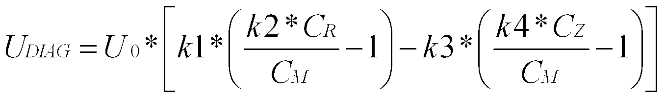
wobei Folgendes gilt:where:
k1 = Verstärkungsfaktor Messzweig
k2 = Null-Abgleichfaktor Messzweig
k3 = Verstärkungsfaktor Kontrollmesszweig
k4 = Null-Abgleichfaktor Kontrollmesszweig.k1 = amplification factor measuring branch
k2 = zero adjustment factor measuring branch
k3 = amplification factor control measuring branch
k4 = zero adjustment factor control measuring branch.
Die Korrekturfaktoren k1 bis k4 werden vorteilhafterweise durch abgleichbare Widerstandsnetzwerke realisiert; ihre Platzierungen in der dargestellten Formel soll nur ein Beispiel aufzeigen und können selbstverständlich je nach beabsichtigter Proportionalitätsrichtung geändert werden.The correction factors k1 to k4 are advantageously realized by tunable resistor networks; their placements in the illustrated formula are intended to be exemplary only and, of course, may be changed depending on the intended direction of proportionality.
Ein Mediumseintritt bzw. ein Membranbruch wirkt sich nur auf die Kapazitätswerte der zwei Kondensatoren CR und CM bzw. nur auf den Kapazitätswert eines dieser beiden Kondensatoren, jedoch nicht auf CZ aus, so dass in diesem Fall die Spannung UDIAG merklich von Null abweicht. Diese Abweichung kann von einem Mikrocontroller (nicht gezeigt) registriert und eine entsprechende Reaktion eingeleitet werden. Diese kann z. B. in einer Alarmmeldung bestehen, die an die SPS weitergeleitet wird oder einer Vor-Ort-Signalisierung.A medium entry or a diaphragm rupture only has an effect on the capacitance values of the two capacitors C R and C M or only on the capacitance value of one of these two capacitors, but not on C Z , so that in this case the voltage U DIAG noticeably decreases from zero differs. This deviation can be registered by a microcontroller (not shown) and a corresponding reaction initiated. This can, for. B. exist in an alarm message, which is forwarded to the PLC or an on-site signaling.
Fig. 5 zeigt eine etwas abgewandelte Schaltung 30b, die ohne ein Sample&Hold-Glied arbeitet. Der Vorteil gegenüber der Ausführung in Fig. 4 besteht darin, dass der Schaltungsaufwand reduziert und damit die Herstellungskosten reduziert werden können. Allerdings wird durch das rechteckförmige Diagnosesignal die Interpration erschwert. Die dargestellten Widerstände sind in Fig. 5 nur symbolisch gemeint und können jeweils auch ein Widerstandsnetzwerk umfassen. Die Messspannung UR ist wie in den zuvor beschriebenen Ausführungen eine Rechteckspannung. Deshalb wird das Diagnosesignal UDIAG in diesem Fall rechteckförmig ausgegeben. Beide Schaltungen 30a, 30b sind sowohl für eine analoge als auch eine digitale Weiterverarbeitung mit einem Mikrocontroller geeignet.Fig. 5 shows a somewhat modified circuit 30b which operates without a sample and hold element. The advantage over the embodiment in Fig. 4 is that the circuit complexity is reduced and thus the manufacturing cost can be reduced. However, the rectangular diagnosis signal makes the interpration more difficult. The illustrated resistors are only symbolically meant in FIG. 5 and may each include a resistor network. The measuring voltage U R is a square-wave voltage as in the previously described embodiments. Therefore, the diagnostic signal U DIAG is output in a rectangular manner in this case. Both circuits 30a, 30b are suitable for both analog and digital further processing with a microcontroller.
Nachfolgend ist das erfindungsgemäße Verfahren näher erläutert.The method according to the invention is explained in more detail below.
Wie bereits in den vorherigen Ausführungsbeispielen angegeben, weist die Druckmesszelle 10 des kapazitiven Drucksensors 1 einen Messkondensator CM und einen Referenzkondensator CR auf. Der Druckmesswert p, z. B. die Spannung UR, wird vorteilhafterweise über ein Quotientenverfahren aus den Kapazitätswerten des Messkondensators CM und des Referenzkondensators CR gewonnen. Erfindungsgemäß wird mit Hilfe eines Zusatzkondensators CZ ebenfalls über ein Quotientenverfahren ein Kontrolldruckmesswert p’, z. B. die Spannung UD, gewonnen. Da der Zusatzkondensator CZ so angeordnet ist, dass er von einem Membranbruch der Membran 14 bzw. von einem Mediumseintritt in die Druckmesszelle 10 völlig unbeeinflusst bleibt, ändern sich die beiden Messwerte in jedem Fall unterschiedlich. As already indicated in the previous exemplary embodiments, the pressure measuring cell 10 of the capacitive pressure sensor 1 has a measuring capacitor C M and a reference capacitor C R. The pressure reading p, z. As the voltage U R, is advantageously obtained by a quotient method from the capacitance values of the measuring capacitor C M and the reference capacitor C R. According to the invention with the aid of an additional capacitor C Z also via a quotient method, a control pressure measured value p ', z. B. the voltage U D won. Since the additional capacitor C Z is arranged so that it remains completely unaffected by a membrane rupture of the membrane 14 or by a medium inlet into the pressure measuring cell 10, the two measured values change in each case differently.
Durch den Vergleich dieser beiden Messwerte kann somit auf die Funktionsfähigkeit der Druckmesszelle geschlossen werden. Solange sich beide Messwerte mit dem Prozessdruck gleichmäßig ändern ist die Funktionsfähigkeit der Druckmesszelle gewährleistet.By comparing these two measured values can thus be concluded on the functionality of the pressure measuring cell. As long as both measured values change evenly with the process pressure, the functionality of the pressure measuring cell is guaranteed.
Der Kontrolldruckmesswert p’ kann sowohl mit dem Messkondensator CM als auch mit dem Referenzkondensator CR ermittelt werden. The control pressure measured value p 'can be determined both with the measuring capacitor C M and with the reference capacitor C R.
Für eine einfache Auswertung erfolgt die Kalibrierung des kapazitiven Drucksensors so, dass der Kontrolldruckmesswert p’ und der Druckmesswert p die gleiche funktionale Abhängigkeit vom Prozessdruck aufweisen. Es versteht sich von selbst, dass Teile der Auswerteschaltung 30a auch digital in einem Mikrocontroller realisiert sein können. Die Erfindung erlaubt es ohne großen Aufwand einen bestehenden kapazitiven Drucksensor um eine Diagnosefunktion zu erweitern. For a simple evaluation, the calibration of the capacitive pressure sensor takes place so that the control pressure measured value p 'and the pressure measured value p have the same functional dependence on the process pressure. It goes without saying that parts of the evaluation circuit 30a can also be implemented digitally in a microcontroller. The invention makes it possible to expand an existing capacitive pressure sensor by a diagnostic function without much effort.
Das erfindungsgemäße Verfahren sowie die entsprechende Auswerteschaltung sind nicht nur zur Feststellung eines Mediumeintritts bei einem Membranbruch sondern auch zur Diagnose von Anrissbildungen in der Membran 14 geeignet, weil sich dabei die Biegesteifigkeit der Membran 14 ändert und sich dies unterschiedlich auf den über den Referenzkondensator CR ermittelten Messwert p’ und den über den Messkondensator CM ermittelten Druckmesswert p auswirkt.The method according to the invention and the corresponding evaluation circuit are suitable not only for determining a medium entry in a membrane breakage but also for the diagnosis of cracking in the membrane 14, because in this case the flexural rigidity of the membrane 14 changes and this determined differently on the above the reference capacitor C R. Measured value p 'and the pressure measured value p determined via the measuring capacitor C M.
In Fig. 6 ist vereinfacht dargestellt, wie sich die drei Kapazitätswerte CM, CR, CZ über dem Druck verhalten. Der Kurve des Messkondensator CM hat die größte Steigung, weil er sich in der Mitte der Membran 14 der Druckmesszelle 10 befindet und damit bei Druckeinfluss die Membran 14 hier die größte Durchbiegung aufweist. Der Referenzkondensator CR befindet sich am Rand der Membran 14, wo die Abstandsänderung zwischen den beiden Elektroden R, ME geringer ist. Daher ist die Kapazitätszunahme je Druckeinheit geringer als beim Messkondensator CM. Zu erkennen ist schließlich, dass sich die Kapazität des Zusatzkondensators CZ nicht ändert und über dem gesamten Druckverlauf konstant bleibt. Das ist die wesentliche Bedingung der Erfindung. Der Pfeil zwischen CM und CR verdeutlicht den betragsmäßigen Verlauf der eigentlichen Messspannung UR, der Pfeil zwischen CM und CZ den betragsmäßigen Verlauf der Ausgangsspannung UD des Kontrollmesszweigs KMZ. FIG. 6 shows in simplified form how the three capacitance values C M , C R , C Z behave above the pressure. The curve of the measuring capacitor C M has the largest slope, because it is located in the middle of the diaphragm 14 of the pressure measuring cell 10 and thus the diaphragm 14 has the greatest deflection under the influence of pressure here. The reference capacitor C R is located at the edge of the membrane 14, where the change in distance between the two electrodes R, ME is lower. Therefore, the capacity increase per unit pressure is less than the measuring capacitor C M. It can finally be seen that the capacity of the additional capacitor C Z does not change and remains constant over the entire pressure curve. That is the essential condition of the invention. The arrow between C M and C R illustrates the magnitude of the actual measurement voltage U R , the arrow between C M and C Z the magnitude of the output voltage U D of the control measuring branch KMZ.
Figur 7 zeigt ein Diagramm, das das Verhalten der Diagnosespannung UDIAG bei den drei Zuständen kein Druck, Druckeinfluss vorhanden und Zellendefekt durch Mediumseintritt vereinfacht darstellt. Vereinfacht dargestellt bedeutet, dass es sich hierbei um eine Prinzipskizze handelt, so dass sich tatsächliche Signalverläufe geringfügig, insbesondere betragsmäßig anders darstellen könnten. Auch wurden weitere Einflüsse, wie resistive Fehler o. dgl., nicht berücksichtigt. Der grundsätzliche Signalverlauf wurde aber einer tatsächlichen Messung nachempfunden. Die Signale UA und UA’ an den Punkten A bzw. A’ sind die durch die Sample-and-Hold-Schaltung zu Gleichspannung umgewandelten Ausgangssignale UR und UD des Differenzierzweigs DZ und des Kontrollmesszweigs KMZ. Die Spannung UDIAG ist die Diagnosespannung als Differenz der beiden Signale UA und UA’. Das Diagramm verdeutlicht somit die Arbeitsweise der Vergleichereinheit VE.FIG. 7 shows a diagram which shows the behavior of the diagnosis voltage U DIAG in the three states no pressure, pressure influence and cell defect due to medium entry. Simplified means that this is a schematic diagram, so that actual waveforms could be slightly different, especially in terms of amount. Also, other influences, such as resistive errors o. The like., Not considered. The fundamental signal course was modeled after an actual measurement. The signals U A and U A ' at the points A and A' are the converted by the sample-and-hold circuit to DC voltage output signals U R and U D of the differentiating branch DZ and the control measuring branch KMZ. The voltage U DIAG is the diagnostic voltage as the difference between the two signals U A and U A ' . The diagram thus clarifies the operation of the comparator unit VE.
Im ersten Drittel des Diagramms liegt kein Druck an der Membran 14 an. Sowohl die beiden Signale UA und UA’ als auch die Diagnosespannung UDIAG zeigen deshalb den Wert Null an. In the first third of the diagram no pressure is applied to the membrane 14. Both the signals U A and U A ' and the diagnostic voltage U DIAG therefore indicate the value zero.
Im zweiten Drittel des Diagramms wurde beispielhaft eine Druckbelastung der Membran 14 von 50 % angenommen. Da die Signalrichtung bei steigendem Druck negativ verläuft, bewegen sich die beiden Signale UA und UA’ aufgrund des vorherigen Abgleichs deckungsgleich unterhalb der 0V-Linie. Die Diagnosespannung UDIAG als Differenz der beiden Signale UA und UA’ ist demnach weiterhin Null. Die stufenartigen Signalverläufe von A und A’ sind bedingt durch die abwechselnd und dadurch zeitversetzten Aktualisierungen der Sample-and-Hold-Kondensatoren an A+ und A-, deren Beträge der Ladespannungen erst addiert den Druckwert repräsentieren.In the second third of the diagram, a pressure load of the membrane 14 of 50% was assumed by way of example. Since the signal direction is negative with increasing pressure, the two signals U A and U A ' move congruently below the 0V line due to the previous adjustment. The diagnostic voltage U DIAG as a difference between the two signals U A and U A ' is therefore still zero. The step-like signal waveforms of A and A 'are due to the alternately and thereby delayed updates of the sample-and-hold capacitors to A + and A-, the amounts of the charging voltages only added the pressure value represent.
Im letzten Drittel des Diagramms sind die Signalverläufe bei einem Mediumseintritt dargestellt, wiederum bei angenommenen 50% Druckbelastung. Da sich jetzt das zu messende Medium innerhalb der Messzelle befindet, d.h. in dem durch den Grundkörper 12 und der Membran 14 begrenzten Hohlkörper 19, herrscht somit der gleiche Druck wie außerhalb der Membran 14 und die jetzt vergrößerte Permittivität wirkt sich auf den Betrag des Quotienten nicht aus. Folglich bewegt sich das Signal UA als Maß für die eigentliche Messspannung UMess in Richtung 0 Volt. Ein stufenförmiger Signalverlauf ergibt sch wieder durch die Sample-and-Hold-Schaltung S&H. Das Signal UA’ bewegt sich hingegen aufgrund der weiterhin konstanten Kapazität CZ, die im Zähler des Quotienten zur Berechnung von UA’ steht, und der wegen vergrößerter Permittivität einseitig größer werdenden Kapazität CM, die im Nenner des Quotienten zur Berechnung von UA’ steht, weiter in negative Richtung. Die Diagnosespannung UDIAG als Differenz der beiden Signale UA und UA’ bewegt sich nun deutlich in positive Richtung. Zumindest – und das ist das Entscheidende – ist die Diagnosespannung UDIAG ungleich Null, was als Maß für einen Zellendefekt erkannt und weiterverarbeitet werden kann. The last third of the diagram shows the signal curves at medium entry, again assuming a 50% pressure load. Since now the medium to be measured is located within the measuring cell, ie in the hollow body 19 delimited by the main body 12 and the membrane 14, the same pressure prevails as outside the membrane 14 and the now increased permittivity does not affect the amount of the quotient out. Consequently, the signal U A moves as a measure of the actual measurement voltage U measurement in the direction of 0 volts. A step-shaped waveform yields sch again through the sample-and-hold circuit S & H. The signal U A ' , however, moves due to the still constant capacitance C Z , which is in the numerator of the quotient for calculating U A' , and due to increased permittivity unilaterally increasing capacity C M , in the denominator of the quotient for the calculation of U A ' stands, in a negative direction. The diagnostic voltage U DIAG as a difference between the two signals U A and U A ' now moves clearly in the positive direction. At least - and that is the decisive factor - the diagnostic voltage U DIAG is not equal to zero, which can be recognized as a measure of a cell defect and further processed.
In Figur 8 ist eine zu den Figuren 4 und 5 alternative Ausführungsform des erfindungsgemäßen Verfahrens dargestellt. Die Druckmesszelle 10 ist dabei identisch zu den zuvor beschriebenen Ausführungsbeispielen. Die durch den Druckeinfluss resultierenden Kapazitätsänderungen von CM und CR werden jedoch nicht analog, sondern digital in einer Verarbeitungseinheit 50, bestehend aus wenigstens einer Konverter-Einheit 55 und einem Mikrocontroller 51, ausgewertet. Dazu ist es zunächst erforderlich, dass die Kapazitätswerte von CM und CR erfasst und digitalisiert werden. Hierfür ist eine Konverter-Einheit 55 vorgesehen, die bspw. als AD7745-Schaltkreis "Capacitance To Digital Converter" von Analog Devices ausgeführt sein kann. In Fig. 8 ist für beide Kondensatoren CM und CR jeweils eine Konverter-Einheit 55 vorgesehen. Es gibt aber auch mehrkanalige Konverter-Einheiten, so dass mit einer Konverter-Einheit mehrere Kapazitäten erfasst und digitalisiert werden können. Die digitalisierten Kapazitätswerte von CM und CR werden dann einem Mikrocontroller 51 zugeführt, in dessen Prozessoreinheit 52 die Quotiententerme CR/CM-1 und CZ/CM-1 errechnet und in der bereits zuvor beschriebenen Weise durch Differenzbildung miteinander vergleichen werden. Der Wert für CZ kommt dabei entweder, wie in Fig. 8 dargestellt, aus einer Speichereinheit 53, die sich vorzugsweise innerhalb des Mikrocontrollers 51 befindet und in der ein einen Zusatzkondensator CZ darstellender Kapazitätswert hinterlegt ist, oder alternativ von einem außerhalb der Verarbeitungseinheit 50 angeordneten, als Bauteil oder Komponente ausgeführten Kondensator, dessen Kapazität ebenfalls von einer Konvertereinheit 55 erfasst und digitalisiert dem Mikrocontroller 51 zugeführt wird. In beiden Fällen muss aber sichergestellt sein, dass die Kapazität CZ von einem Membranbruch der Membran 14 bzw. von einem Mediumseintritt in die Druckmesszelle 10 völlig unbeeinflusst bleibt. Das Ergebnis dieses Vergleichs, d.h. liegt ein Fehlerfall vor oder nicht, wird dann als Diagnosewert 52a neben dem eigentlichen Messwert 52b zur weiteren Verarbeitung weitergeben.FIG. 8 shows an alternative embodiment of the method according to the invention to FIGS. 4 and 5. The pressure measuring cell 10 is identical to the previously described embodiments. However, the capacitance changes of C M and C R resulting from the pressure influence are not evaluated analogously but digitally in a processing unit 50 consisting of at least one converter unit 55 and a microcontroller 51. For this, it is first necessary that the capacitance values of C M and C R are recorded and digitized. For this purpose, a converter unit 55 is provided which, for example, can be designed as an AD7745 circuit "Capacitance To Digital Converter" by Analog Devices. In FIG. 8, a converter unit 55 is provided for both capacitors C M and C R. But there are also multi-channel converter units, so that with a converter unit several capacities can be detected and digitized. The digitized capacitance values of C M and C R are then fed to a microcontroller 51, in whose processor unit 52 the quotient terms C R / C M -1 and C Z / C M -1 are calculated and compared in the previously described manner by subtraction , The value for C Z either comes, as shown in FIG. 8, from a memory unit 53, which is preferably located within the microcontroller 51 and in which a capacitance value representing an additional capacitor C Z is stored, or alternatively from outside the processing unit 50 arranged, designed as a component or component capacitor whose capacitance is also detected by a converter unit 55 and digitized the microcontroller 51 is supplied. In both cases, however, it must be ensured that the capacitance C Z remains completely uninfluenced by a membrane rupture of the membrane 14 or by a medium inlet into the pressure measuring cell 10. The result of this comparison, that is, an error case or not, will then pass on as diagnostic value 52a next to the actual measured value 52b for further processing.
Claims (10)
- Verfahren zur Funktionsüberwachung einer Druckmesszelle (10) eines kapazitiven Drucksensors (1), wobei die Druckmesszelle (10) einen Messkondensator (CM) und einen Referenzkondensator (CR) aufweist und der Druckmesswert (p) aus den Kapazitätswerten des Messkondensators (CM) und des Referenzkondensators (CR) gewonnen wird,Method for monitoring the function of a pressure measuring cell (10) of a capacitive pressure sensor (1), wherein the pressure measuring cell (10) has a measuring capacitor (C M ) and a reference capacitor (C R ) and the pressure measured value (p) from the capacitance values of the measuring capacitor (C M ) and the reference capacitor (C R ) is obtained,dadurch gekennzeichnet, dass mit einem Zusatzkondensator (CZ), der außerhalb der Druckmesszelle (10) angeordnet ist, ein Kontrolldruckmesswert (p’) gewonnen wird und durch Vergleich des Druckmesswertes (p) mit dem Kontrolldruckmesswert (p’) auf die Funktionsfähigkeit der Druckmesszelle (10) geschlossen wird. characterized in that with an additional capacitor (C Z ), which is arranged outside the pressure measuring cell (10), a control pressure measured value (p ') is obtained and by comparing the pressure measurement value (p) with the control pressure measured value (p') on the functioning of the pressure measuring cell (10) is closed.
- Verfahren zur Funktionsüberwachung einer Druckmesszelle (10) eines kapazitiven Drucksensors (1), wobei die Druckmesszelle (10) einen Messkondensator (CM) und einen Referenzkondensator (CR) aufweist und der Druckmesswert (p) aus den Kapazitätswerten des Messkondensators (CM) und des Referenzkondensators (CR) gewonnen wird,Method for monitoring the function of a pressure measuring cell (10) of a capacitive pressure sensor (1), wherein the pressure measuring cell (10) has a measuring capacitor (C M ) and a reference capacitor (C R ) and the pressure measured value (p) from the capacitance values of the measuring capacitor (C M ) and the reference capacitor (C R ) is obtained,dadurch gekennzeichnet, dass eine Verarbeitungseinheit (50), bestehend aus wenigstens einer Konverter-Einheit (55) und einem Mikrocontroller (51), vorgesehen ist, in der die Kapazitätswerte des Messkondensators (CM) sowie des Referenzkondensators (CR) erfasst werden, aus beiden Kapazitätswerten der Druckmesswert (p) gebildet wird und in der ein weiterer Kapazitätswert erfasst wird, der einem Zusatzkondensator (CZ) entspricht und aus dem ein Kontrolldruckmesswert (p’) gewonnen wird, wobei durch Vergleich des Druckmesswertes (p) mit dem Kontrolldruckmesswert (p’) auf die Funktionsfähigkeit der Druckmesszelle (10) geschlossen wird. characterized in that a processing unit (50) is provided, comprising at least one converter unit (55) and a microcontroller (51), in which the capacitance values of the measuring capacitor (C M ) and the reference capacitor (C R ) are detected, from both capacitance values of the pressure measurement (p) is formed and in which a further capacitance value is detected, which corresponds to an additional capacitor (C Z ) and from which a control pressure reading (p ') is obtained, wherein by comparing the pressure measurement value (p) with the control pressure measured value (P ') on the functioning of the pressure measuring cell (10) is closed.
- Verfahren nach Anspruch 2,Method according to claim 2,dadurch gekennzeichnet, dass der Zusatzkondensator (CZ) als Bauteil außerhalb der Druckmesszelle (10) ausgeführt ist, dessen Kapazitätswert von der Verarbeitungseinheit (50) erfasst wird.characterized in that the additional capacitor (C Z ) is designed as a component outside the pressure measuring cell (10) whose capacity value is detected by the processing unit (50).
- Verfahren nach Anspruch 2,Method according to claim 2,dadurch gekennzeichnet, dass der Zusatzkondensator (CZ) in Form eines in der Verarbeitungseinheit (50), insbesondere im Mikrocontroller (51) abgespeicherten Kapazitätswerts ausgeführt ist.characterized in that the additional capacitor (C Z ) in the form of a in the processing unit (50), in particular in the microcontroller (51) stored capacitance value is executed.
- Verfahren nach einem der vorhergehenden Ansprüche, Method according to one of the preceding claims,dadurch gekennzeichnet, dass der Druckmesswert (p) und/oder der Kontrolldruckmesswert (p’) mit Hilfe eines Quotientenverfahrens gewonnen wird. characterized in that the pressure measurement value (p) and / or the control pressure measurement value (p ') is obtained by means of a quotient method.
- Verfahren nach einem der vorhergehenden Ansprüche, Method according to one of the preceding claims,dadurch gekennzeichnet, dass der Kontrolldruckmesswert (p’) aus den Kapazitätswerten des Messkondensators (CM) und des Zusatzkondenstors (CZ) gewonnen wird.characterized in that the control pressure measured value (p ') is obtained from the capacitance values of the measuring capacitor (C M ) and the Zusatzkondenstors (C Z ).
- Verfahren nach einem der Ansprüche 1 bis 5,Method according to one of claims 1 to 5,dadurch gekennzeichnet, dass der Kontrolldruckmesswert (p´) aus den Kapazitätswerten des Referenzkondensators (CR) und des Zusatzkondensators (CZ) gewonnen wird.characterized in that the control pressure measured value (p ') is obtained from the capacitance values of the reference capacitor (C R ) and the additional capacitor (C Z ).
- Verfahren nach einem der vorhergehenden Ansprüche, Method according to one of the preceding claims,dadurch gekennzeichnet, dass der kapazitive Drucksensor (1) so kalibriert ist, dass der Kontrolldruckwert (p’) und der Druckmesswert (p) die gleiche funktionale Abhängigkeit vom Prozessdruck aufweisen und ein Fehlerfall vorliegt, wenn die Differenz von Druckmesswert (p) und Kontrolldruckwert (p’) einen vorgegebenen Grenzwert überschreitet. characterized in that the capacitive pressure sensor (1) is calibrated such that the control pressure value (p ') and the pressure measurement value (p) have the same functional dependence on the process pressure and an error occurs if the difference between pressure measurement value (p) and control pressure value (p) p ') exceeds a predetermined limit.
- Auswerteschaltung für einen kapazitiven Sensor (1), insbesondere Drucksensor, mit einem Messkondensator (CM)und einem Referenzkondensator (CR), wobei der Referenzkondensator (CR) in einem Differenzierzweig (DZ) und der Messkondensator (CM) in einem Integrierzweig (IZ) vorgesehen ist, die beide parallel geschaltet sind und mit einem Spannungssignal beaufschlagt werden, wobei das Ausgangssignal des Integrierzweiges (IZ) dem Differenzzierzweig (DZ) zugeführt wird, an dessen Ausgang ein erstes druckabhängiges Ausgangssignal (UR) anliegt,Evaluation circuit for a capacitive sensor (1), in particular pressure sensor, with a measuring capacitor (C M ) and a reference capacitor (C R ), wherein the reference capacitor (C R ) in a differentiating branch (DZ) and the measuring capacitor (C M ) in an integrating branch (IZ) is provided, which are both connected in parallel and are acted upon by a voltage signal, wherein the output signal of the integrating branch (IZ) the Differenzzierzweig (DZ) is supplied to the output of which a first pressure-dependent output signal (U R ) is applieddadurch gekennzeichnet, dass parallel zum Differenzierzweig (DZ) ein Kontrollmesszweig (KMZ) mit einem Zusatzkondensator (CZ) geschaltet ist und das Ausgangssignal des Integrierzweiges (IZ) zusätzlich dem Kontrollmesszweig (KMZ) zugeführt wird, an dessen Ausgang ein zweites druckabhängiges Ausgangssignal (UD) anliegt, und beide Ausgangssignale (UR, UD) einer Vergleichereinheit (VE) zugeführt werden, an deren Ausgang ein Diagnosesignal (UDIAG) ausgegeben wird. characterized in that parallel to the differentiating branch (DZ) a control measuring branch (KMZ) with an additional capacitor (C Z ) is connected and the output of Integrierzweiges (IZ) additionally the Kontrollmesszweig (KMZ) is supplied to the output of a second pressure-dependent output signal (U D ), and both output signals (U R , U D ) are fed to a comparator unit (VE), at whose output a diagnostic signal (U DIAG ) is output.
- Auswerteschaltung nach Anspruch 9,Evaluation circuit according to claim 9,dadurch gekennzeichnet, dass der Zusatzkondensator (CZ) außerhalb der Druckmesszelle (10) angeordnet ist.characterized in that the additional capacitor (C Z ) outside the pressure measuring cell (10) is arranged.
Priority Applications (2)
| Application Number | Priority Date | Filing Date | Title |
|---|---|---|---|
| US13/883,851 US9316557B2 (en) | 2010-12-08 | 2011-12-07 | Method for self-monitoring a ceramic pressure measuring cell of a capacitive pressure sensor and evaluation circuit for carrying out said method |
| EP11794711.9A EP2606330B1 (en) | 2010-12-08 | 2011-12-07 | Method for the self-monitoring of a ceramic pressure measuring cell of a capacitive pressure sensor and an evaluation circuit for carrying out the method |
Applications Claiming Priority (2)
| Application Number | Priority Date | Filing Date | Title |
|---|---|---|---|
| DE102010062622A DE102010062622A1 (en) | 2010-12-08 | 2010-12-08 | Method for self-monitoring of a ceramic pressure measuring cell of a capacitive pressure sensor and an evaluation circuit for carrying out the method |
| DE102010062622.8 | 2010-12-08 |
Publications (2)
| Publication Number | Publication Date |
|---|---|
| WO2012076615A2 true WO2012076615A2 (en) | 2012-06-14 |
| WO2012076615A3 WO2012076615A3 (en) | 2012-08-02 |
Family
ID=45346460
Family Applications (1)
| Application Number | Title | Priority Date | Filing Date |
|---|---|---|---|
| PCT/EP2011/072119 WO2012076615A2 (en) | 2010-12-08 | 2011-12-07 | Method for the self-monitoring of a ceramic pressure measuring cell of a capacitive pressure sensor and an evaluation circuit for carrying out the method |
Country Status (4)
| Country | Link |
|---|---|
| US (1) | US9316557B2 (en) |
| EP (1) | EP2606330B1 (en) |
| DE (1) | DE102010062622A1 (en) |
| WO (1) | WO2012076615A2 (en) |
Families Citing this family (11)
| Publication number | Priority date | Publication date | Assignee | Title |
|---|---|---|---|---|
| DE102014201529A1 (en) | 2014-01-28 | 2015-07-30 | Siemens Aktiengesellschaft | Method for operating a pressure transmitter and pressure transmitter |
| US9869599B2 (en) * | 2014-09-30 | 2018-01-16 | Rosemount Inc. | High-temperature pressure sensing |
| DE102014118616A1 (en) * | 2014-12-15 | 2016-06-16 | Endress + Hauser Gmbh + Co. Kg | pressure transducers |
| US9897504B2 (en) * | 2015-04-20 | 2018-02-20 | Infineon Technologies Ag | System and method for a MEMS sensor |
| EP3244272A1 (en) * | 2016-05-09 | 2017-11-15 | Siemens Aktiengesellschaft | Method for monitoring a condenser pressure protection curve with polygon function |
| US9983032B1 (en) * | 2017-06-01 | 2018-05-29 | Nxp Usa, Inc. | Sensor device and method for continuous fault monitoring of sensor device |
| DE102018118645B3 (en) | 2018-08-01 | 2019-11-07 | Ifm Electronic Gmbh | Method for monitoring the function of a pressure measuring cell of a capacitive pressure sensor |
| DE102018121463A1 (en) * | 2018-09-03 | 2020-03-05 | Ifm Electronic Gmbh | Capacitive pressure sensor with a pressure measuring cell and an evaluation unit, which are spatially separated from each other |
| DE102019124083B3 (en) | 2019-09-09 | 2020-10-22 | Ifm Electronic Gmbh | Absolute pressure measuring device with a relative measuring pressure measuring cell |
| DE102019129264B4 (en) * | 2019-10-30 | 2021-07-15 | Ifm Electronic Gmbh | Method for monitoring the function of a capacitive pressure measuring cell |
| DE102020122128B3 (en) | 2020-08-25 | 2021-11-04 | Ifm Electronic Gmbh | Method for monitoring the function of a capacitive pressure measuring cell |
Citations (2)
| Publication number | Priority date | Publication date | Assignee | Title |
|---|---|---|---|---|
| EP0569573B1 (en) | 1991-11-28 | 1996-04-10 | Endress + Hauser Gmbh + Co. | Capacitive manometer with a highly linear response |
| DE19851506C1 (en) | 1998-11-09 | 2000-10-19 | Ifm Electronic Gmbh | Capacitive sensor evaluation method e.g. for pressure sensor, has periodic input signal supplied simultaneously to integration path containing reference capacitor and series circuit containing resistor and sensor capacitor |
Family Cites Families (13)
| Publication number | Priority date | Publication date | Assignee | Title |
|---|---|---|---|---|
| DE3932443C1 (en) * | 1989-09-28 | 1990-12-20 | Endress U. Hauser Gmbh U. Co, 7864 Maulburg, De | |
| US5613398A (en) * | 1994-01-24 | 1997-03-25 | Chrysler Corporation | Smart fuel tank module |
| US5663506A (en) * | 1995-08-21 | 1997-09-02 | Moore Products Co. | Capacitive temperature and pressure transducer |
| DE19648048C2 (en) * | 1995-11-21 | 2001-11-29 | Fuji Electric Co Ltd | Detector device for pressure measurement based on measured capacitance values |
| DE19633630A1 (en) * | 1996-08-21 | 1998-02-26 | Endress Hauser Gmbh Co | Evaluation unit of a differential pressure sensor |
| DE69936794T2 (en) * | 1999-08-20 | 2008-04-30 | Hitachi, Ltd. | SEMICONDUCTOR PRESSURE SENSOR AND DEVICE FOR DETECTING PRINTING |
| EP1677084A1 (en) * | 2004-12-22 | 2006-07-05 | Roxer Industries S.A. | LIquid level sensor and method of estimation |
| JP2008008688A (en) | 2006-06-27 | 2008-01-17 | Yamatake Corp | Capacitance-type pressure sensor |
| US20080301211A1 (en) | 2007-06-01 | 2008-12-04 | United States of America as represented by the Administrator of the National Aeronautics and | Systems, methods and apparatus for d-dimensional formulation and implementation of recursive hierarchical segmentation |
| EP2189774B1 (en) * | 2008-11-20 | 2014-12-31 | VEGA Grieshaber KG | Method of detecting and compensating for a quick temperature change to a pressure measurement cell |
| US8281655B2 (en) * | 2009-04-03 | 2012-10-09 | Eaton Corporation | Fuel gauging system utilizing a digital fuel gauging probe |
| DE102009002662B4 (en) * | 2009-04-27 | 2022-11-24 | Ifm Electronic Gmbh | Capacitive pressure sensor as a combination sensor for recording other measured variables |
| DE102010001797B4 (en) * | 2010-02-11 | 2023-09-28 | Robert Bosch Gmbh | Micromechanical sensor element for capacitive differential pressure detection |
-
2010
- 2010-12-08 DE DE102010062622A patent/DE102010062622A1/en not_active Withdrawn
-
2011
- 2011-12-07 EP EP11794711.9A patent/EP2606330B1/en active Active
- 2011-12-07 WO PCT/EP2011/072119 patent/WO2012076615A2/en active Application Filing
- 2011-12-07 US US13/883,851 patent/US9316557B2/en active Active
Patent Citations (2)
| Publication number | Priority date | Publication date | Assignee | Title |
|---|---|---|---|---|
| EP0569573B1 (en) | 1991-11-28 | 1996-04-10 | Endress + Hauser Gmbh + Co. | Capacitive manometer with a highly linear response |
| DE19851506C1 (en) | 1998-11-09 | 2000-10-19 | Ifm Electronic Gmbh | Capacitive sensor evaluation method e.g. for pressure sensor, has periodic input signal supplied simultaneously to integration path containing reference capacitor and series circuit containing resistor and sensor capacitor |
Also Published As
| Publication number | Publication date |
|---|---|
| EP2606330A2 (en) | 2013-06-26 |
| US20130269412A1 (en) | 2013-10-17 |
| EP2606330B1 (en) | 2014-09-24 |
| US9316557B2 (en) | 2016-04-19 |
| DE102010062622A1 (en) | 2012-06-14 |
| WO2012076615A3 (en) | 2012-08-02 |
Similar Documents
| Publication | Publication Date | Title |
|---|---|---|
| EP2606330B1 (en) | Method for the self-monitoring of a ceramic pressure measuring cell of a capacitive pressure sensor and an evaluation circuit for carrying out the method | |
| EP1882930B1 (en) | Circuit and method for measuring humidity | |
| EP2994725B1 (en) | Method and apparatus for monitoring of at least one specific property of a fluid medium for a level measurement | |
| DE102009002662B4 (en) | Capacitive pressure sensor as a combination sensor for recording other measured variables | |
| DE102019129264B4 (en) | Method for monitoring the function of a capacitive pressure measuring cell | |
| DE19851506C1 (en) | Capacitive sensor evaluation method e.g. for pressure sensor, has periodic input signal supplied simultaneously to integration path containing reference capacitor and series circuit containing resistor and sensor capacitor | |
| DE102020122128B3 (en) | Method for monitoring the function of a capacitive pressure measuring cell | |
| DE102018118646B3 (en) | Method for monitoring the function of a pressure measuring cell of a capacitive pressure sensor | |
| DE102011083133B4 (en) | Method for self-monitoring of a ceramic pressure measuring cell of a capacitive pressure sensor and an evaluation circuit for carrying out the method | |
| DE102018118645B3 (en) | Method for monitoring the function of a pressure measuring cell of a capacitive pressure sensor | |
| DE102022105693B3 (en) | Method for operating a pressure measuring cell of a capacitive pressure sensor | |
| EP3696514B1 (en) | Sensor assembly and method for operating a sensor assembly | |
| EP0460407B1 (en) | Sensor circuit | |
| DE102014224221A1 (en) | Position measuring device and method for determining positions of a measuring object | |
| WO2019115369A1 (en) | Sensor device for detecting electrically conductive media, and method for operating the sensor device | |
| DE102020100675A1 (en) | Capacitive pressure sensor with temperature detection | |
| DE102022120883B3 (en) | Process for monitoring the function of a capacitive pressure measuring cell | |
| DE4001274C2 (en) | ||
| DE102018126382B3 (en) | Capacitive pressure sensor | |
| DE102014224222A1 (en) | Capacitive measuring sensor and position measuring device for determining a position of a measuring object and positioning device with such a measuring sensor | |
| DE102018105234B4 (en) | Method for operating a capacitive pressure measuring device | |
| DE102014201153B4 (en) | Electronic pressure switch | |
| DE102010040932A1 (en) | Method for configuring capacitive pressure measuring arrangement to determine e.g. soot-amount rate of soot particulate filter in exhaust line of motor car, involves selecting parameters of transfer function to minimize function deviation | |
| DE102018121463A1 (en) | Capacitive pressure sensor with a pressure measuring cell and an evaluation unit, which are spatially separated from each other | |
| DE102007043070A1 (en) | Measuring circuit for measuring e.g. pressure in brake pressure line of vehicle, has comparator device for comparing potentials at nodes of network and outputting evaluation signal depending on difference of potentials |
Legal Events
| Date | Code | Title | Description |
|---|---|---|---|
| 121 | Ep: the epo has been informed by wipo that ep was designated in this application |
Ref document number: 11794711 Country of ref document: EP Kind code of ref document: A2 |
|
| WWE | Wipo information: entry into national phase |
Ref document number: 2011794711 Country of ref document: EP |
|
| WWE | Wipo information: entry into national phase |
Ref document number: 13883851 Country of ref document: US |